( 12 ) united states patent
TRANSCRIPT

US010778282B1
( 12 ) United States Patent Hanif et al .
( 10 ) Patent No .: US 10,778,282 B1 ( 45 ) Date of Patent : Sep. 15 , 2020
( 56 ) References Cited ( 54 ) METHODS FOR IMPROVING FLEXIBILITY AND DATA RATE OF CHIRP SPREAD SPECTRUM SYSTEMS IN LORAWAN U.S. PATENT DOCUMENTS
5,090,024 A * 2/1992 Vander Mey ( 71 ) Applicant : Cisco Technology , Inc. , San Jose , CA
( US )
H04B 1/69 370/479
H04B 1/69 370/447
5,574,748 A * 11/1996 Vander Mey
( 72 ) Inventors : Muhammad Hanif , Saskatoon ( CA ) ; Ha Hoang Nguyen , Saskatoon ( CA )
5,748,670 A 8,526,483 B2 *
5/1998 Zastrow 9/2013 Choi HO4B 3/54
375/139 9,083,444 B2 9,094,107 B1 * HO4L 27/103 ( * ) Notice :
7/2015 Schaffner 7/2015 Kumar
( Continued ) Subject to any disclaimer , the term of this patent is extended or adjusted under 35 U.S.C. 154 ( b ) by 0 days .
OTHER PUBLICATIONS
( 21 ) Appl . No .: 16 / 520,986
( 22 ) Filed : Jul . 24 , 2019
Related U.S. Application Data ( 60 ) Provisional application No. 62 / 844,297 , filed on May
7 , 2019 .
( 51 ) Int . Ci . H04B 1/7176 ( 2011.01 ) H04B 1/7093 ( 2011.01 ) H04B 1/69 ( 2011.01 )
( 52 ) U.S. CI . CPC H04B 1/7176 ( 2013.01 ) ; H04B 1/7093
( 2013.01 ) ; H04B 2001/6912 ( 2013.01 ) ; H04B 2001/70935 ( 2013.01 )
( 58 ) Field of Classification Search CPC H04B 1/69 ; H04B 1/707 ; H04B 1/7093 ;
HO4B 1/7176 ; H04B 2001/6912 ; H04B 2203/5441 ; H04B 3/54 ; H04L 27/103 ;
HO4L 7/06 See application file for complete search history .
SemTech , " SX1276 / 77 / 78 / 79—137 MHz to 1020 MHz Low Power Long Range Transceiver , ” Aug. 2016 .
( Continued ) Primary Examiner Khanh C Tran ( 74 ) Attorney , Agent , or Firm — Edell , Shapiro & Finnan , LLC
( 57 ) ABSTRACT A transmitter stores mappings of distinct values of an information signal to corresponding ones of distinct com binations of K chirps taken from M chirps that are different from each other , such that each of the distinct values is mapped to a corresponding one of the distinct combinations of K chirps . The transmitter receives a distinct value among the distinct values of the information signal . The transmitter selects , based on the mappings , a distinct combination of K chirps among the distinct combinations of K chirps that is mapped to the distinct value . The transmitter sums the K chirps of the distinct combination of K chirps to produce a symbol that represents the distinct value . The transmitter modulates the symbol to produce a modulated symbol , and transmits the modulated symbol . A receiver receives a modulated symbol that conveys a distinct value , and recov ers the distinct value using stored mappings .
20 Claims , 8 Drawing Sheets
1 102
CHIRPS SELECTOR TRANSMITTER 118
126 SUM PULSE SHAPING
+ V / Q MODULATOR * DIA CHANNEL
INTERPOLATION INFORMATION SIGNAL 122
MAPPER nghawe ni
-106
1
RECEIVER IQ DEMODULATOR 152 150
RU i M - POINT yn SYNCHRONIZATION
DEMAPPER JALGORITHM 1
SIP MATCHED ALTER
146 -142
mo

US 10,778,282 B1 Page 2
( 56 ) References Cited
U.S. PATENT DOCUMENTS
9,479,216 B2 9,647,718 B2
2008/0310479 Al 2010/0039313 A1 *
10/2016 Harrison et al . 5/2017 Seller 12/2008 Koslar et al . 2/2010 Morris
2016/0124075 A1 * 5/2016 Vogt
GO1S 7/006 342/25 F
GO1S 13/325 342/13
GO1S 7/03 GO1S 7/032
2019/0250264 A1 2019/0285725 Al *
8/2019 Belfiore 9/2019 Roger
OTHER PUBLICATIONS
H. L. Schneider , “ Data transmission with FSK permutation modu lation , ” The Bell System Technical Journal , vol . 47 , pp . 1131-1138 , Jul . 1968 . D. Slepian , “ Permutation modulation , ” Proceedings of the IEEE , vol . 53 , Issue 3 , pp . 228-236 , Mar. 1965 . T. Elshabrawy and J. Robert , “ Interleaved Chirp Spreading Loka Based Modulation , ” IEEE Internet of Things Journal , Early Access , Jan. 2019 . Zorbas , Dimitrios et al . , “ Improving LoRa Network Capacity Using Multiple Spreading Factor Configurations ” , 10.1109 / ICT.2018 . 8464901 , Jun . 2018 , 5 pages .
* cited by examiner

110
RE
***
BEI ?
7 102
100
112
U.S. Patent
SELECTOR
TRANSMITTER
CHIRPS xom Xyln Xan
116
118
104
126
128
108
SUM
PULSE SHAPING + INTERPOLATION 1 / Q MODULATOR + DIA
CHANNEL
?
Xa [ n ]
120
INFORMATION SIGNAL 122
XM - 3 [ 0 ] XM - 2 ! XM - INO
Sep. 15 , 2020
MAPPER
1
1
106
140
RECEIVER
152
Sheet 1 of 8
1 / Q DEMODULATOR + A / D
150
148
147
RO RU
YO SYNCHRONIZATION
DEMAPPER PA JALGORITHM
M - POINT DFT
S / P
MATCHED FILTER
RM - 11
146
- 142
US 10,778,282 B1
FIG.1

U.S. Patent Sep. 15 , 2020 Sheet 2 of 8 US 10,778,282 B1
NE 2 ? ~ BW 2
? 2 BW 2 ? ~ BW FIG.2A
? ? ? 7
( 1 ) x
N
? ~ ? ? slev ? 2 ( 1 )

uuis 90 0.5 1.5 0
0 C
-20 €
We
www * ? ya ! Mert
***
** hohem ************ Www
mtu mzima wa Motta FIG.2B W W SWAR WWWWEKAK MA WANA WA WI WA MARA YA MWWWW WA WA MAMA WA KAKA WA AMAA WANARA W Aw ??? ? ? ? ??? ??? ??? ??? ??? ?? ??? ,
304
* www
OL www
wan
www . Wow ******************* Voir
RAM AD
MIXER ** * WWWWWW *** www .
US 10,778,282 B1 Sheet 3 of 8 Sep. 15 , 2020 U.S. Patent
M LANVIN CMS WMUW
with the
MY MINEM
GA

100
U.S. Patent
10
RSSONS
102
Sep. 15 , 2020
103 BER
104
Sheet 4 of 8
105 106
CONVENTIONAL CSS ( N = 128 , K = 1 ) B. CONVENTIONAL CSS ( M = 256 , K = 1 ) PROPOSED SCHEME ( N = 128 , K = 2 ) PROPOSED SCHEME ( N = 256 , K - 2 )
WANNA
10 "
0
1
2
3
4
5
6
US 10,778,282 B1
*******
E / N [ dB ] FIG.3
Citation ou d'UTELLAMCOXWTDIDO
U.S. Patent
107 2:01
Sep. 15 , 2020
YO
Sheet 5 of 8
* ( N = 128 , K = 1 ) ( M = 256 , K = 1 )
S.OL
( M = 128 , K = 2 )
-12
-10
US 10,778,282 B1
( N = 256 , K = 2 )
SNR ( dB ] FIG.4

U.S. Patent Sep. 15 , 2020 Sheet 6 of 8 US 10,778,282 B1
502 STORE MAPPINGS OF DISTINCT VALUES OF AN INFORMATION SIGNAL TO CORRESPONDING
ONES OF DISTINCT COMBINATIONS OF K FREQUENCY CHIRPS TAKEN FROM M FREQUENCY CHIRPS THAT
ARE DIFFERENT FROM EACH OTHER , WHEREM > K > = 1 , SUCH THAT EACH OF THE DISTINCT VALUES IS
MAPPED TO A CORRESPONDING ONE OF THE DISTINCT COMBINATIONS OF K FREQUENCY CHIRPS
504 RECEIVE A DISTINCT VALUE AMONG THE
DISTINCT VALUES OF THE INFORMATION SIGNAL
506 SELECT , BASED ON THE MAPPINGS , A DISTINCT COMBINATION OF K FREQUENCY CHIRPS AMONG
THE DISTINCT COMBINATIONS OF K FREQUENCY CHIRPS THAT IS MAPPED TO THE DISTINCT VALUE
508 SUM THEK FREQUENCY CHIRPS OF THE
DISTINCT COMBINATION OF K FREQUENCY CHIRPS TO PRODUCE A SYMBOL THAT REPRESENTS THE
DISTINCT VALUE
510 MODULATE THE SYMBOL TO PRODUCE A MODULATED
SYMBOL
512
TRANSMIT THE MODULATED SYMBOL
FIG.5

U.S. Patent Sep. 15 , 2020 Sheet 7 of 8 US 10,778,282 B1
600
602 STORE MAPPINGS OF DISTINCT VALUES OF AN
INFORMATION SIGNAL TO CORRESPONDING ONES OF DISTINCT COMBINATIONS OF K FREQUENCY CHIRPS
TAKEN FROM M FREQUENCY CHIRPS THAT ARE DIFFERENT FROM EACH OTHER , WHERE M > > = 1
604 RECEVE ( FROM A TRANSMITTER ) A MODULATED VERSION
OF A SYMBOL THAT REPRESENTS ONE OF THE DISTINCT VALUES AS A SUMMATION OF THE FREQUENCY CHIRPS OF ONE OF THE
DISTINCT COMBINATIONS OF K FREQUENCY CHIRPS
606 DECHIRP THE MODULATED VERSION OF THE SYMBOL
TO RECOVER A DECHIRPED SYMBOL
608 PROCESS THE DECHIRPED SYMBOL TO PRODUCE AN
INDICATION OF THE ONE OF THE DISTINCT COMBINATIONS OF K FREQUENCY CHIRPS
610 DEMAP , BASED ON THE MAPPINGS , THE INDICATION OF THE
ONE OF THE DISTINCT COMBINATIONS OF K FREQUENCY CHIRPS TO THE ONE OF THE DISTINCT VALUES
FIG.6

WIRELESS DEVICE 700
U.S. Patent
705
CONTROLLER 707
PROCESSOR
Sep. 15 , 2020
703
709
( COMMUNICATION CHANNELS )
RADIO
MEMORY
724
715
CONTROL LOGIC
Sheet 8 of 8
DATA
WIRED VF TO WIRED NETWORK oooooooooooooo
NETWORK INTERFACE FIG.7
US 10,778,282 B1

US 10,778,282 B1 1 2
METHODS FOR IMPROVING FLEXIBILITY FIG . 7 is a block diagram of a wireless device configured AND DATA RATE OF CHIRP SPREAD to implement embodiments presented herein , according to SPECTRUM SYSTEMS IN LORAWAN an example embodiment .
PRIORITY CLAIM 5 DESCRIPTION OF EXAMPLE EMBODIMENTS
10
15
This application claims priority to U.S. Provisional Patent Overview Application No. 62 / 844,297 , filed May 7 , 2019 , incorpo In a transmitter embodiment , a transmitter stores map rated by reference herein in its entirety . pings of distinct values of an information signal to corre
sponding ones of distinct combinations of K chirps taken TECHNICAL FIELD from M chirps that are different from each other , where
M > K > = 1 , such that each of the distinct values is mapped to The present disclosure relates to generating and demodu a corresponding one of the distinct combinations of K
lating chirp spread spectrum signals . chirps . The transmitter receives a distinct value among the distinct values of the information signal . The transmitter
BACKGROUND selects , based on the mappings , a distinct combination of K chirps among the distinct combinations of K chirps that is
Long range ( LoRa ) technology as used in a LoRa wide mapped to the distinct value . The transmitter sums the K area network ( WAN ) ( LoRaWAN ) enables large communi 20 chirps of the distinct combination of K chirps to produce a cation coverage by using the technique of chirp spread symbol that represents the distinct value . The transmitter spectrum ( CSS ) . CSS is reasonably flexible in providing modulates the symbol to produce a modulated symbol , and tradeoffs between reception sensitivity and throughput . transmits the modulated symbol . Spreading factor ( SF ) is an important parameter in CSS In a receiver embodiment , a receiver stores mappings of modulation . Increasing SF can significantly extend the com- 25 distinct values of an information signal to corresponding munication range , but it comes at the cost of a lower ones of distinct combinations of K chirps taken from M transmission rate . Another important parameter is the band chirps that are different from each other , where M > K > = 1 . width ( BW ) . Currently , three BW settings are available in The receiver receives a modulated version of a symbol that LoRa systems : 125 kHz , 250 kHz , and 500 kHz . In general , represents a distinct value among the distinct values as a providing different BW settings in LoRa modems results in 30 summation of the K chirps of a distinct combination of K expensive transceivers as additional hardware is required for chirps among the distinct combinations of K chirps . The the provision . Furthermore , there can be applications that receiver dechirps the modulated version of the symbol to require higher data rates than what can be supported using recover a dechirped symbol , and processes the dechirped the maximum BW and lowest SF selection currently avail symbol to produce an indication of the distinct combination able with LoRa . A conventional frequency - shift keying 35 of K chirps . Based on the mappings , the receiver demaps the ( FSK ) transceiver may be provided for such applications . indication of the distinct combination of K chirps to the
distinct value . Including an FSK transceiver adds hardware cost and soft ware complexity . Example Embodiments
BRIEF DESCRIPTION OF THE DRAWINGS The embodiments are described below first at a high
level , and then in detail . The embodiments are described FIG . 1 is a block diagram of a CSS system ( i.e. , the with reference to a conventional CSS system so that advan " proposed CSS scheme " ) according to an example embodi tages of the embodiments and their business values are ment . 45 readily understood . FIG . 2A shows frequency spectrums of eight chirps used The conventional CSS system ( e.g. , LoRa system )
in the CSS system , according to an example embodiment . includes a transmitter and a receiver that use a set of M = 2 SF FIG . 2B is an illustration of a transmitted signal including chirps , each carrying SF = log2 M information bits . A chirp is
two symbols for the CSS system , according to an example a signal in which the frequency increases or decreases over embodiment . 50 time , i.e. , which has a swept frequency that either increases FIG . 3 is a plot of a bit error rate ( BER ) comparison of a or decreases with time . As such , a chirp is also called a
conventional CSS scheme and the proposed CSS scheme for sweep signal , and one chirp typically sweeps through the are spreading factor ( SF ) = 7 , 8 ( equivalently , M = 128 , 256 , chirp bandwidth BW once ( as in the LoRa system ) , or twice where M is a total number of chirps in a set of available ( as in the Institute of Electrical and Electronics Engineers chirps ) and K = 1 , 2 ( wherein K is a number of chirps of the 55 ( IEEE ) 802.15.4a standard ) . When the instantaneous fre M chirps that are summed ) , according to an example quency of the sweep signal of the chirp reaches the highest , embodiment . it will wrap - over and start from the lowest frequency . The
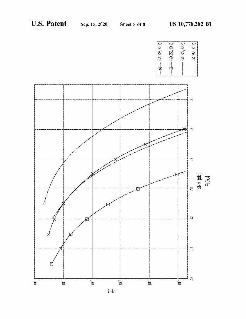
FIG . 4 is a plot of a packet error rate ( PER ) comparison transmitter operates as follows . First , each group of SF bits of a conventional CSS scheme and the proposed CSS provided to an input of the transmitter is used to select one scheme for SF = 7,8 ( equivalently , M = 128 , 256 ) and K = 1 , 2 , 60 chirp ( also known as a symbol ) for transmission ( i.e. , there according to an example embodiment . is a one - to - one mapping from a group of SF bits to one of FIG . 5 is a flowchart of an example transmit method M chirps ) . The receiver receives the transmission ( i.e. , the
performed in the CSS system , according to an example received signal ) and performs quadrature demodulation , embodiment . analog - to - digital conversion and synchronization operations FIG . 6 is a flowchart of an example receive method 65 on the received signal . A signal resulting from the afore
performed in the CSS system , according to an example mentioned operations is processed by multiplying that signal embodiment . with the conjugate of a basic chirp , followed by a discrete
40

M !
10
25
US 10,778,282 B1 3 4
Fourier transform ( DFT ) . The DFT bin having the maximum magnitude identifies the chirp that was transmitted . A main disadvantage of the conventional CSS system is K ! ( M - K ) !
its low data throughput . Embodiments presented herein alleviate this shortcoming by leveraging the technique of 5 distinct values m and a corresponding total number of permutation modulation . The basic idea employed in the distinct combinations of K chirps . embodiments is that , instead of transmitting only one chirp In operation , mapper 120 receives one of the distinct in any given symbol duration , a sum of multiple chirps is values m of information signal 122 , generates the distinct transmitted . The number of chirps that are used in the sum combination of K indexes , represented as Im , that is mapped is a system design parameter . In particular , if K out of M to the one of the distinct values m based on the mappings , chirps are used in the sum , the total number of unique sums and provides Im to selector 112 as a control input to the is precisely the number of combinations in taking K objects selector . Responsive to Im , selector 112 simultaneously out of M objects , which is selects the distinct combination of K chirps corresponding
15 to / represented by Im from the M chirps , and presents the K chirps simultaneously to parallel inputs of summer 114. In
M ! this way , selector 112 time - aligns the K chirps to be simul K ! ( M - K ) ! taneous with each other . Summer 114 sums the K simulta
neous chirps to produce a transmit symbol 126 ( also referred Depending on the choice of K , this number could be much 20 to simply as a “ symbol ” ) that represents the one of the greater than M , i.e. , Ñ >> M . Since the number of informa distinct values m received by mapper 122. That is , the
summation of the distinct combination of the K simultane tion bits that can be carried by each sum is log , Ñ this ous chirps ( i.e. , symbol 126 ) represents the one of the number can be much bigger than SF = log2 M , which means distinct values m that is received by mapper 122. In the that a CSS system that operates in accordance with the embodiment of FIG . 1 , each of the M chirps includes a embodiments can achieve a much higher data rate than the respective sequence of M complex samples / values ( i.e. , each conventional CSS system . The embodiments also include a chirp is represented as a complex - valued discrete - time sig low - complexity DFT - based receiver that can detect the nal ) , such that summer 114 performs a complex sample - wise particular chirps that were used to generate the transmitted ( i.e. , complex sample - by - complex sample ) summation signal ( i.e. , the sum signal ) at the transmitter , hence recov- 30 across the K simultaneous chirps , to produce symbol 126 as ering the information bits . a complex - valued discrete - time symbol . That is , summer
Further details of the embodiments are now described . In 114 sums the sequences of the complex values of the K the ensuing description , various embodiments may also each chirps of the K simultaneous chirps to produce symbol 126 . be referred to as a “ proposed scheme . ” Pulse shaping and interpolation module 116 includes ( i ) a
With reference to FIG . 1 , there is shown a simplified 35 pulse shaping filter , such as a root - raised cosine filter , to block diagram of an example CSS system 100 that operates filter the complex - valued discrete - time symbol , and ( ii ) an according to the embodiments presented herein . The CSS interpolator to interpolate the complex - valued discrete - time system 100 includes a transmitter 102 that transmits chirps signal , to produce a filtered , interpolated , complex - valued or symbols in a signal 104 to a receiver 106 through a discrete - time symbol 128 ( i.e. , an interpolated version of the communication channel 108. The transmitter 102 and the 40 complex - valued discrete - time symbol ) . I / Q modulator and D / A converter module 118 includes ( i ) a complex D / A receiver 106 are also collectively referred to as a “ proposed converter to convert complex - valued discrete - time symbol transceiver . ” The transmitter 102 includes memory to store 128 to a complex - valued continuous - time symbol , and ( ii ) a set 110 of M orthogonal chirps , a chirp selector 112 , a an I / Q ( i.e. , complex ) modulator to modulate the complex summer 114 , a pulse shaping and interpolation module 116 , valued continuous - time symbol to produce a modulated an In - phase / Quadrature ( I / Q ) modulator and digital - to - ana symbol / chirp in signal 104 . log ( D / A ) converter module 118 , and a mapper 120. First , a The operation of the transmitter 102 is now described in high - level description of the transmitter 102 is described . detail with reference to the following mathematical treat Then a mathematical treatment of operation of the transmit ment . The transmitter 102 uses the total of M orthogonal ter will be provided . In the embodiment of FIG . 1 , the M 50 chirps for representing the information bits ( e.g. , informa chirps ( i.e. , chirps 0 to M - 1 ) are assigned corresponding tion signal 122 ) provided to the transmitter . The M chirps in ones of M indexes 0 to M - 1 used to identify / indicate and the set of chirps 110 are denoted as xo [ n ] , x , [ n ] , ... , XM - 1 [ n ] access the chirps individually and in combinations . Thus , the ( in the time The basic chirp is denoted M chirps may be represented by corresponding ones of the sequence or series of M complex samples ( also referred to M indexes . The transmitter 102 includes mapper 120 that 55 as complex values ) xo [ n ] , given as stores mappings of distinct values m ( i.e. , all of the values m are different from one another ) of an information signal 122 to corresponding ones of distinct combinations of K n2 ( 1 )
x [ n ] 127 = 0 , 1 , ... , M - 1 . chirps taken from the M chirps , such that each of the distinct values m is mapped to a corresponding one of the distinct 60 combinations of K chirps . To do this , in the embodiment of FIG . 1 , mapper 120 maps the distinct values m to corre The remaining chirps are related to the basic chirp as sponding ones of distinct combinations of K indexes , such that each of the distinct values m is mapped to a correspond Xx [ n ] = xo [ n + k ] , k = 0,1 , ... M - 1 , ( 2 )
ing one of the distinct combinations of K indexes , and thus 65 Note that xo [ n ] is periodic with period M , i.e. , xo [ n + to a corresponding one of the distinct combinations of K M ] , [ n ] . Therefore , all the chirps can be generated by chirps through the K indexes . This yields a total number of cyclic shifts of xo [ n ] .
45
a
= .. n =

6
TABLE 1
No. Pattern
US 10,778,282 B1 5
FIG . 2A shows chirp frequency spectrums X ( f ) , X ( f ) , X2 ( f ) , X3 ( f ) , X_ ( f ) , X ( f ) , X ( f ) , and X , ( f ) for time domain chirps , xo [ n ] , x , [ n ] , x2 [ n ] , x3 [ n ] , x4 [ n ] , x5 [ n ] , xo [ n ] , and Xq [ n ] , respectively . In the frequency spectrums of FIG . 3 , “ n ” represents a sample - time index . As shown in FIG . 2A , 5 chirp frequency spectrums X ( f ) , X2 ( f ) , X3 ( f ) , X_ ( f ) , X ; ( f ) , X ( f ) , and X , ( f ) represent respective , successively , cycli cally frequency - shifted versions of the basic chirp frequency spectrum X ( f ) , for which the successive cyclic frequency shifts are equal to each other . As described above in connection with FIG . 1 , the first
step in the transmission process of the proposed scheme is mapping a group of information bits to a symbol , as pro vided by mapper 120. In the proposed scheme , every group of A bits is mapped to one transmit symbol . Let bo , 15 b1 , ... , b , be transmitted bits . Then , m is defined to be the corresponding decimal number , i.e. ,
OHMtiONO 10
11000000 10100000 10010000 10001000 10000100 10000010 10000001 01100000 01010000 01001000 01000100 01000010 01000001 00110000 00101000 00100100 00100010 00100001 00011000 00010100 00010010 00010001 00001100 00001010 00001001 00000110 00000101 00000011
4 5 6 7 8 9
10 11 12 13 14 15 16 17 18 19 20 21 22 23 24 25 26 27
A - 1
A - 1 20 m = ?6,2 ' .
i = 0
Note that Osms24-1 . The transmitter 102 uses a total of K chirps simultane- 25
ously to represent m . In particular , for every ( distinct ) value of m between 0 and 24-1 , the transmitter assigns a unique and distinct combination of K chirps . Specifically , let a distinct combination or set of indexes Im , with ImI = K , denote the index set of the chirps corresponding to the 30 message m . Then the transmitted signal ( i.e. , symbol ) cor responding to the message m is constructed as
1 ( 3 ) 35 Sm [ n ] = te ??? [ n ] .
In Table 1 , a “ 1 ” in a row corresponds to a selection of the corresponding chirp . Since A = 4 , only the first 24 = 16 pat terns are selected for transmission and reception . Note that the combination of indexes Im can be found easily from the pattern . For example , Im corresponding to the pattern 10000100 is Im = { 0,5 ) . Thus , the distinct bit pattern 10000100 is mapped to the distinct combination of Im 0,5 , which is in turn mapped to the distinct combination of K = 2 chirps xo [ n ] , x , [ n ] .
With reference to FIG . 2B , there is an illustration of an example of a sequence of two symbols generated by the transmitter 102 , e.g. , at the output of summer 114 or at the output of pulse shaping and interpolation module 116 , for the case ( M = 8 ) ( i.e. , SF = 3 ) and K = 2 . Here the first symbol 302 ( which may repr sent symbol 126 or symbol 128 , for example ) is sm [ n ]
lelm
Since there is a total of 40
M
K ! ( M - K ) !
45
1 combinations of K chirps out of Mchirps , the number of bits that are mapped to ( carried by ) one symbol is given as : Sm [ n ] - ( x [ n ] + xx [ n ] ) ,
A = [ log2 ( ) ] . ( 4 )
It is pointed out that the conventional CSS system ( e.g. , 50 and the second symbol 304 is LoRa system ) corresponds to the choices of M = SF , K = 1 , Im = { m } , and A = SF . In contrast , in the proposed scheme , the number of chirps M need not to be a power of 2 .
Consider a simple example for M = 8 . In the conventional Sm [ n ] = ter ( x3 [ n ] + x6 [ n ] ) . V2 CSS system , a total of 8 different messages can be trans- 55 mitted . Since Im = { m } for m = 0 , 1 , ... , 7 , Equation ( Eq . ) ( 3 ) simplifies to Each symbol 302 , 304 is complex and includes a real
component / waveform shown in solid line and an imaginary Sm [ n ] = xm [ n ] . ( 5 ) component / waveform shown in dashed line . Equivalently ,
In the proposed scheme , if K = 2 is chosen , there are a total 60 Im = { 0,5 } and Im = { 3,6 } for the first and second symbols , of ( M ) = ( 28 ) = 28 combinations of two chirps . Consequently , respectively . Note that sm [ n ] is a complex - valued discrete A = [ log2 ( 28 ) ] = 4 . This means that the transmitter 102 can time signal , which is converted to a continuous - time signal transmit 4 bits instead of 3 bits in every symbol when two and modulated by I / Q modulator and D / A module 118 chirps are selected simultaneously . This translates to a before transmission to the channel . data - rate improvement of 33 % . Table 2 below shows the number of bits in a multiple
Table 1 below shows all 28 combinations corresponding chirp symbol and a percentage of data - rate improvement . to a selection of 2 out of 8 chips . Table 2 tabulates the number of bits that symbol can carry
65

10
SF = K 15
1 2 3 4 5
7 8
386 % 413 % 422 % 9
10 11 19
7 8
9 10 11 12
12 14 16 18 20 22
171 % 175 % 178 % 180 % 182 % 183 %
18 21 24 27 30 33
20
257 % 263 % 267 % 270 % 273 % 275 %
23 27 31 35 39 43
329 % 338 % 344 % 350 % 355 % 358 %
27 33 38 43 48 53
436 % 442 %
25
US 10,778,282 B1 7 8
in the proposed scheme for different values of M when K A serial - to - parallel ( S / P ) converter 147 of the receiver 106 chirps are selected for transmission . Note that with conven converts the sequence of samples of r [ n ] to M parallel tional CSS ( e.g. , LoRa ) modulation , K = 1 , and total of samples and provides them to parallel inputs of a DFT SF = log2 ( M ) bits are transmitted per symbol , as also shown module 148. DFT module 148 performs an M - point DFT on in Table 2. Also indicated in Table 2 is the percentage of 5 the M parallel samples of r [ n ] , to produce an M - point DFT data - rate improvement gained through selecting K chirps having complex ( DFT ) amplitudes R [ O ] , R [ 1 ] , ... , R [ M - 1 ] instead of 1 chirp only . For example , for SF = 12 and K = 3 , in corresponding frequency bins having corresponding one symbol can convey a total of 33 bits instead of only 12 indexes 0 , 1 , ... , M - 1 . An algorithm module 150 executes bits when only one chirp is selected . In other words , the data an algorithm “ Algorithm 1 ” that processes the DFT ampli rate is now 2.75 times the data rate achievable by the tudes along with the complex conjugate of the basic chirp , conventional CSS modulation . to produce an indication of the one of the distinct combi
nations of K chirps that is mapped to the one of the distinct TABLE 2 values conveyed by the symbol . In the embodiment of FIG .
1 , the indication represents the one of the distinct combina tions of K indexes , e.g. , Im , that corresponds to the one of the distinct combinations of K chirps and that , in turn , is mapped log2 M to the one of the distinct values m conveyed in the symbol . The algorithm module 150 provides the indication , e.g. , Ima to a demapper 152 of the receiver 106. As described below ,
430 % to determine the set of indexes Im , Algorithm 1 successively determines individual indexes belonging to Im ( i.e. , con structs the set of indexes Im , one index at a time ) using a recursive algorithm that , for each current iteration of the
Referring again to FIG . 1 , first , a high - level description of algorithm , selects / identifies one index of Im . the receiver 106 is described , then a mathematical treatment Demapper 152 stores the mappings described above .
Demapper 152 demaps the indication Im provided by algo of the operation of the receiver 106 will be provided . The rithm module 150 to the one of the distinct values m receiver 106 stores at least the basic chirp xo [ n ] of the total conveyed in the symbol based on the stored mappings , and set of M chirps used at the transmitter 102 , but may also outputs the one of the distinct values m . In other words , store all of the M chirps . Like the transmitter 102 , the 30 demapper 152 translates the indication Im to m . receiver 106 also stores mappings of the distinct values m of The operation of the receiver 106 , in particular , Algorithm the information signal 122 to the corresponding ones of 1 , is now described in detail with reference to the following distinct combinations of K frequency chirps ( also referred to mathematical treatment . In a frequency - flat channel with an as “ chirps ” ) taken from the M chirps . The receiver 106 may equivalent complex baseband channel gain h ( which is store the aforementioned mappings , indirectly , as mappings 35 typically less than one , indicating path or transmission loss ) , of the distinct values m to the corresponding ones of the the maximum - likelihood ( ML ) detection for transmission in distinct combinations of K indexes , which represent indirect the proposed scheme is given as mappings from the distinct values m to the distinct combi nations of K indexes , as described above in connection with the transmitter 102 . ( 6 ) In operations , the receiver 106 receives a signal including argn a modulated symbol transmitted by the transmitter 102. As VK mentioned above , the modulated symbol is a modulated version of a symbol that represents one of the distinct values m as a summation of the K ( simultaneous ) chirps of the one 45 where y = [ y [ 0 ] y [ 1 ] . y [ M – 1 ] ] , x = [ [ x , [ 0 ] x [ 1 ] of the distinct combinations of K chirps that is mapped to the x ; [ M – 1 ] ] , y [ n ] = hs [ n ] + w [ n ] is the received signal , and one of the distinct values . The signal including the modu w [ n ] is a circularly - symmetric Gaussian noise with lated symbol is provided to an I / Q demodulator and analog variance No. Simplifying ( 6 ) gives to - digital ( A / D ) module 140 of the receiver . I / Q demodula tor and analog - to - digital ( A / D ) module 140 includes ( i ) a 50 quadrature down - converter to demodulate and frequency în = argmaxR { h * y 4 downconvert the signal to a complex - valued continuous time signal ( e.g. , at baseband ) , and ( ii ) a complex A / D converter to convert the complex - valued continuous - time signal to a complex - valued discrete - time signal . A synchro- 55 where h * and x , are the conjugate and hermitian trans nization and matched filter module 142 of the receiver 106 poses of h and xz , respectively , and R { } denotes the performs matched filtering of the complex - valued discrete real part of a complex number . time signal , and synchronizes receiver phase and timing to When a receiver ( e.g. , the receiver 106 ) does not have the the complex - valued discrete - time signal , to produce a signal knowledge of h , which is the case of practical interest , the y [ n ] . Signal y [ n ] represents a dechirped signal from which 60 receiver estimates m using the following non - coherent ML the frequency sweep has been removed and that retains detection rule : information from / associated with ( e.g. , contained in ) the symbol .
Receiver 106 includes a multiplier 146 to multiply the ( 8 ) complex conjugate of the basic chirp by the signal y [ n ] that 65 retains the information from the symbol , to produce a resulting signal r [ n ] including a sequence of samples / values .
40
lelm
* a { w » { * } lelm
H
în = argmanty 2
k ] R [ I ]
US 10,778,282 B1 9 10
Observe that account , i.e. , effectively removes , the known contribution of the known first chirp ( indexed by 1. ) from the combined contributions of the first and second chirps to a total energy
20 / x { [ n ] = xo [ / ] xo [ n ] explj xo [ Lx " ) . of the symbol , which permits the remaining unknown index 1 , of the second chirp to be estimated / determined in the next iteration .
Consequently , Eq . ( 8 ) can be written as For K > 2 , the detection scheme is carried out similarly . In particular , the elements of Im = { 1 ,, 12 , ... , 1x } are detected one at a time recursively as
? 2 x xoll r [ n ] e Î1 = argmaxx « [ / ] R [ ? ] ] = argmax | R [ ? ] ] , ( 13 )
5
10 M - 1 ( 9 ) - jk 2 n / M ñ = argmax
m lelm
n = 0 m lelm { {
and where r [ n ] = y [ n ] x . * [ n ] , and R [ l ] , 1-0 , 1 , . M - 1 , is the 15
discrete Fourier transform ( DFT ) of r [ n ] . It is pointed out that , for the conventional CSS modula
tion , Im = { m } . Since Ix . * [ m ] I = 1 , the detection rule in Eq . ( 9 ) becomes ( 14 )
Ik + 1 = - argomastersuppen + EKGL.IRL ) . 20
m
a
ñ = argmax | R [ m ] l . ( 10 ) for k = 1 , 2 , ... , K - 1 . In Eq . ( 14 ) , the second term , i.e. , the summation term ,
In other words , the sampled received signal y [ n ] ( after 25 represents the total contribution to the symbol of all chirps synchronization ) is first multiplied by the conjugate of the having indexes that were determined in previous iterations . basic chirp , and an M - point DFT is applied on the resultant As described above , the summation ( which may be a sub signal . Afterwards , the message is demodulated by identi traction ) removes the known contributions , which leaves the fying the index of the peak absolute value of the DFT output . unknown contribution from which the unknown index may Unsurprisingly , this is exactly the same as the optimal 30 be determined . In other words , each iteration removes the non - coherent detection of CSS signals . known contributions ( which increase through each iteration ) A case that is relevant to the proposed scheme is when so that the unknown contribution may be determined .
K > 1 . In this case , an optimal receiver would require a search Algorithm 1 below shows example pseudocode for the over all the patterns used at the transmitter to find i that detection scheme , which also labelled in FIG . 1 , i.e. , in maximizes 161 , X0 * [ 1 ] R [ 1 ] ] ( which represents a correlated 35 algorithm module 150. Here , recursive function energy term or contribution ) . However , the optimal receiver INDEXSETESTIMATOR is used to describe the aforementioned consumes a high quantity of computational resources and recursive method . memory . Accordingly , the proposed scheme includes a Algorithm 1 Low - Complexity Detection Algorithm of the detection scheme in the receiver that significantly reduces Proposed Flexible CSS Modulation Scheme . both the computational complexity and memory . 40 Input : K , y [ n ] for n = 0 , 1 , ... , M - 1
The detection scheme finds Im in a recursive manner . In Output : 1m particular , the detection scheme estimates / determines the 1 : Compute r [ n ] = y [ n ] x . * [ n ] for n = 0 , 1 , ... , M - 1 elements ( denoted 1 , ) of Im one at a time . For example , for 2 : Compute R = DFT ( [ r [ 0 ] r [ 1 ] ... r [ M - 1 ] ] ) K = 2 , let Im = { 1 ,, 12 } . The detection scheme first estimates 1 , 3 : I / INDEXSETESTIMATOR ( R , K )
4 : function INDEXSETESTIMATOR ( R , K ) 5 : if K = 1 then 6 : return { argmax | R [ 1 ] ] }
( 11 ) 11 = argmax | R [ ] ) . 7 : else 8 : { în , ... , Îx - 1 } < INDEXSETESTIMATOR ( R , K - 1 ) 9 : IK Fargmax , lx . * [ 1 ] R [ 1 ] + ? m = K - 1x , * [ TM ] R [ Îm ] 10 : return { în , ... , ÎK } Note that ( 11 ) estimates 1 , exactly the same way as is done 11 : end if
for the case K = 1 ( see ( 10 ) ) . Once 1 , is estimated , 12 can be 12 : end function estimated / determined in a next iteration using Eq . ( 9 ) as The proposed scheme can be used to improve the bit error 55 rate ( BER ) performance of the conventional CSS modula
tion . To demonstrate this advantage , FIG . 3 shows the BER În = argmax [ x6 L?I ] R [ Î1 ] + x [ { ] R [ / ] ] . ( 12 ) performance of the conventional scheme ( K = 1 ) and the
proposed scheme ( K = 2 ) for SF = 7 , 8 ( or M = 128 , 256 ) . Observe that , in either the conventional scheme ( e.g. , con
Because the symbol of interest represents a summation of 60 ventional LoRa ) or the proposed scheme , the BER perfor contributions from first and second chirps indexed by 11 and mance is better when a higher number of chirps is used 12 , the first term of the summation in Eq . ( 12 ) represents a ( M = 256 versus M = 125 ) . On the other hand , in either scheme known ( chirp ) contribution ( e.g. , a correlated energy con ( conventional or proposed ) , the data rate is 1.75 times when tribution from the first chirp ) of the first chirp ( indexed by M = 128 is used instead of M = 256 . 11 ) to the symbol representing m . The contribution is known 65 An important observation from FIG . 3 is that , while the because 11 , and thus the first chirp , was determined at Eq . two schemes with ( M , K ) = ( 128 , 1 ) and ( M , K ) = ( 256 , 2 ) ( 11 ) . Accordingly , the summation in Eq . ( 12 ) takes into deliver the same data rate , the proposed scheme with ( M ,
as 45
{
50

US 10,778,282 B1 11 12
K ) = ( 256 , 2 ) performs better than the conventional scheme At 508 , transmitter 102 sums the K chirps of the distinct with ( M , K ) = ( 128 , 1 ) in terms of BER at moderate to high combination of K chirps to produce a symbol that represents E , / N , values . the distinct value . Prior to being summed , the K chirps may
The proposed scheme can increase the highest achievable be time - aligned to be simultaneous with each other when data rate of the conventional CSS modulation with only 5 summed , such that the symbol represents a summation of the slight degradation in BER . To see this , consider again FIG . K simultaneous chirps . 3 , where the BER curve of the proposed scheme with ( M , At 510 , transmitter 102 modulates the symbol to produce K ) = ( 128 , 2 ) is plotted . Observe that the BER performance of a modulated symbol . In an embodiment , prior to being the proposed scheme is only slightly worse than that of the modulated , the symbol may be filtered and interpolated . conventional scheme with SF = 7 ( or M = 128 ) . However , the 10 At 512 , transmitter 102 transmits the modulated symbol . data rate achieved by the proposed scheme with ( M , K ) = In an embodiment , the M chirps are represented in the ( 128 , 2 ) is 12 / 7–1.7143 times that of the maximum data rate transmitter 102 by corresponding ones of M indexes , and the achieved by the conventional scheme . As such , the improved mappings include mappings of the distinct values to corre scheme can be used to improve the data rate of the conven sponding ones of distinct combinations of K indexes taken tional scheme without affecting the BER performance sig- 15 from the M indexes , such that each of the distinct values is nificantly . It should be noted that the data rate can further be mapped to a corresponding one of the distinct combinations improved by using more chirps for transmission and recep of K indexes . Also , at 506 , the transmitter 102 selects a tion , i.e. , by using K > 2 . distinct combination of K indexes among the distinct com
The proposed scheme exhibits similar sensitivity as the binations of K indexes that is mapped to the distinct value conventional CSS modulation . As an illustration , consider 20 based on the mappings . Also , the transmitter accesses the FIG . 4 , where the packet error rates ( PERs ) of both the distinct combination of K chirps using the distinct combi conventional and proposed schemes are shown . Observe that nation of K indexes , and then , at 508 , sums the K chirps to the lower the data rate of a scheme , the better the scheme is produce the symbol . in terms of PER , and vice versa . In FIG . 4 , for example the With reference to FIG . 6 , there is a flowchart of an scheme with ( M , K ) = ( 256 , 1 ) has the lowest PER . At the 25 example receive method 600 that may be performed by the same time , the first scheme has the lowest data rate , whereas receiver 106. Method 600 summarizes operations described the latter has the highest data rate amongst the four schemes above . under comparison . The scheme with ( M , K ) = ( 128 , 1 ) and the At 602 , receiver 106 maps ( and stores resulting mappings scheme with ( M , K ) = ( 256 , 2 ) have the same data rate and of ) distinct values of an information signal to corresponding have almost the same PER performance against the channel 30 ones of distinct combinations of K chirps taken from M Signal - to - Noise ( SNR ) . That is , the improved scheme and chirps that are different from each other . In an embodiment , the conventional scheme have similar reception sensitivity M > K > = 1 ( e.g. , M > K > 2 ) , and the M chirps include a basic for the same data rate . chirp and M - 1 chirps that represent respective cyclic shifts The proposed scheme can be used to transmit / receive of the basic chirp .
conventional CSS signals , too . In particular , selecting only 35 At 604 , receiver 106 receives a modulated version of a one chirp by Im = { m } results in the conventional CSS symbol that represents one of the distinct values ( i.e. , a transmission / reception . This means that a CSS transceiver distinct value among the distinct values ) as a summation of employing the proposed schemed ( i.e. , the proposed trans the K chirps ( which may be simultaneous ) of one of the ceiver ) can communicate with conventional CSS modula distinct combinations of K chirps ( i.e. , a distinct combina tion - based transceivers . In other words , the proposed 40 tion of K chirps among the distinct combinations of K scheme has backward compatibility feature . chirps ) . A wide range of achievable data rates can be obtained by At 606 , receiver 106 dechirps the modulated version of
changing the number of selected chirps , K , without changing the symbol to recover a dechirped signal that retains infor the BW or SF . Since very minimum hardware changes are mation from the symbol . required to achieve variable data rates , the proposed CSS 45 At 608 , receiver 106 processes the dechirped signal to modulation can reduce the hardware costs of the existing produce an indication of the one of the distinct combinations CSS modulation - based transceivers . of K chirps . To process the dechirped signal , the receiver
With reference to FIG . 5 , there is a flowchart of an 106 may ; multiply the dechirped signal by a complex example transmit method 500 that may be performed by the conjugate of the basic chirp to produce a resulting signal , transmitter 102. Method 500 summarizes operations 50 generate a DFT of the resulting signal , wherein the DFT described above . including complex DFT amplitudes in respective frequency
At 502 , transmitter 102 maps ( and stores resulting map bins of the DFT ; and process the complex DFT amplitudes pings of ) distinct values ( e.g. , m ) of an information signal to with the complex conjugate of the basic chirp to produce the corresponding ones of distinct combinations of K chirps one of the distinct combinations of K indexes . As described taken from M chirps that are different from each other , such 55 above , an algorithm to determine / estimate the distinct com that each of the distinct values is mapped to a corresponding bination of K indexes based on the DFT may include one of the distinct combinations of K chirps . In an embodi successively determining indexes of the one of the distinct ment , M > K > = 1 ( e.g. , M > K > 2 ) , and the M chirps include a combinations of K indexes recursively by operating on the basic chirp and M - 1 chirps that represent respective cyclic DFT amplitudes and the complex conjugate of the basic shifts of the basic chirp . Also , the M chirps may employ a 60 chirp . Assuming the symbol includes summed chirps having spreading factor SF according to the LoRa communication respective indexes , the algorithm successively determines standard for a LoRaWAN , wherein M = 2SF each index taking into account , e.g. , removing , correlated At 504 , transmitter 102 receives a distinct value among energy contributions to the symbol of the chirps indexed by
the distinct values of the information signal . previously determined indexes . For example , the algorithm At 506 , transmitter 102 selects , based on the mappings , a 65 ( i ) determines a first index of a first chirp summed into the
distinct combination of K chirps among the distinct combi symbol based on its correlated energy contribution to the nations of K chirps that is mapped to the distinct value . symbol , ( ii ) determines a second index of a second chirp

US 10,778,282 B1 13 14
summed into the symbol taking into account the correlated system , e.g. , a LoRa modem / transceiver . The proposed energy contribution of the first chirp indexed by the first scheme supports a wide range of data rates with minimal index to the symbol , ( iii ) determines a third index of a third hardware changes . chirp summed into the symbol taking into account the Embodiments of the proposed scheme improve the data correlated energy contributions of both the first chirp 5 throughput of a CSS ( e.g. , LoRa ) modem . The embodiments indexed by the first index to the symbol and the second chirp are directed to a CSS system that includes a transmitter and indexed by the second index , and so on . a receiver . The transmitter transmits a signal including a sum At 610 , receiver 106 demaps , based on the mappings , the of multiple concurrent chirps ( i.e. , a sum signal ) in any given
indication of the one of the distinct combinations of K chirps symbol duration to convey information bits , to achieve a 10 much higher data rate compared to a transmitter that trans to the one of the distinct values .
In an embodiment , the M chirps are represented in the mits only a single chirp in the given symbol duration . The receiver employs a low - complexity DFT to detect the par receiver 106 by corresponding ones of M indexes , and the ticular chirps that were used to generate the transmitted mappings include mappings of the distinct values to corre signal ( i.e. , the sum signal ) at the transmitter , hence recov sponding ones of distinct combinations of K indexes taken 15 ering the information bits . The embodiments improve the from the M indexes , such that each of the distinct values is throughput without increasing the BW . Thus , the embodi mapped to a corresponding one of the distinct combinations ments greatly reduce the hardware cost and complexity . of K indexes . Also , the receiver 106 processes the dechirped Furthermore , the embodiments enable high data rates as
signal to produce the indication as one of the distinct supported by an FSK modem . Consequently , the embodi combinations of K indexes that is mapped to the one of the 20 ments eliminate hardware and software modules dedicated distinct values , then , the receiver demaps the one of the to FSK transmission and reception , resulting in a reduced distinct combinations of K indexes to the one of the distinct hardware cost and software complexity . values based on the mappings . The proposed scheme offers several key advantages . First ,
With reference to FIG . 7 , there is shown a block diagram the proposed scheme generalizes the conventional CSS of a wireless device 700 configured to implement embodi- 25 based transmission / reception . For example , the proposed ments presented herein , including transmitter 102 , receiver transceiver can transmit and receive conventional CSS sig 106 , and their respective methods . Wireless device 700 nals when it uses only one chirp to convey information bits ; includes a wireless radio 703 including a radio transmitter however , by using multiple chirps , the proposed transceiver and a radio receiver to transmit and receive CSS signals in can bring significant improvements in the achievable data the form of modulated symbols / chirps . Radio 703 includes 30 rate without affecting the BER performance significantly . a respective set of one or more antennas . Radio 703 per Second , the proposed scheme for data - rate improvement is forms radio frequency and baseband signal processing , all digital , so that permits adjustment of data rates in a digital including various operations described above for the pro way . The proposed scheme only requires modification of the posed scheme . Wireless device 700 may include a wired transmission and reception algorithms , and only slight hard network interface 715 that enables the wireless device to 35 ware modifications . Last , the proposed scheme can eliminate connect to a wired network . the provision of an FSK modem in the conventional LoRa
Wireless device 700 also includes a controller 705 having systems by enabling higher data rates for a given BW and SF a processor 707 and memory 709. Processor 707 is a setting . Hence , the proposed scheme can reduce the hard microcontroller or microprocessor , for example , configured ware cost and software complexities of the existing LoRa to execute software instructions stored in memory 709. 40 modem chips . Memory 709 may comprise read only memory ( ROM ) , The embodiments presented may be in various forms , random access memory ( RAM ) , magnetic disk storage such as a system , a method , and / or a computer program media devices , optical storage media devices , flash memory product at any possible technical detail level of integration . devices , electrical , optical , or other physical / tangible ( e.g. , The computer program product may include a computer non - transitory ) memory storage devices . Thus , in general , 45 readable storage medium ( or media ) having computer read memory 709 may comprise one or more computer readable able program instructions thereon for causing a processor to storage media ( e.g. , a memory device ) encoded with soft carry out aspects of presented herein . ware comprising computer executable instructions and when The computer readable storage medium can be a tangible the software is executed ( by processor 707 ) it is operable to device that can retain and store instructions for use by an perform the operations described herein . For example , 50 instruction execution device . The computer readable storage memory 709 stores or is encoded with instructions for medium may be , for example , but is not limited to , an control logic 714 to perform overall control of wireless electronic storage device , a magnetic storage device , an device 700 and operations to implement the proposed optical storage device , an electromagnetic storage device , a scheme in both transmit and receive directions , e.g. , to semiconductor storage device , or any suitable combination generate symbols from values of an information signal and 55 of the foregoing . A non - exhaustive list of more specific to demodulate symbols to recover the values from the examples of the computer readable storage medium includes symbols as described above . Operations for the proposed the following : a portable computer diskette , a hard disk , a scheme may be shared across radio 703 and controller 705 random access memory ( RAM ) , a read - only memory ( i.e. , control logic 714 ) . ( ROM ) , an erasable programmable read - only memory Memory 709 also stores information / data 724 used and 60 ( EPROM or Flash memory ) , a static random access memory
generated by control logic 714. Such data includes the M ( SRAM ) , a portable compact disc read - only memory ( CD chirps and mappings of the chirps to values of an informa ROM ) , a digital versatile disk ( DVD ) , a memory stick , a tion signal and to indexes . The data also includes correlation floppy disk , a mechanically encoded device such as punch values , DFT amplitudes / values , complex conjugates of cards or raised structures in a groove having instructions chirps , and so on . 65 recorded thereon , and any suitable combination of the fore
In summary , embodiments presented include a highly going . A computer readable storage medium , as used herein , flexible scheme ( i.e. , the proposed scheme ) for a CSS is not to be construed as being transitory signals per se , such

US 10,778,282 B1 15 16
as radio waves or other freely propagating electromagnetic the computer readable storage medium having instructions waves , electromagnetic waves propagating through a wave stored therein comprises an article of manufacture including guide or other transmission media ( e.g. , light pulses passing instructions which implement aspects of the function / act through a fiber - optic cable ) , or electrical signals transmitted specified in the flowchart and / or block diagram block or through a wire . 5 blocks .
Computer readable program instructions described herein The computer readable program instructions may also be can be downloaded to respective computing / processing loaded onto a computer , other programmable data process devices from a computer readable storage medium or to an ing apparatus , or other device to cause a series of operational external computer or external storage device via a network , steps to be performed on the computer , other programmable for example , the Internet , a local area network , a wide area 10 apparatus or other device to produce a computer imple network and / or a wireless network . The network may com mented process , such that the instructions which execute on prise copper transmission cables , optical transmission fibers , the computer , other programmable apparatus , or other wireless transmission , routers , firewalls , switches , gateway device implement the functions / acts specified in the flow computers and / or edge servers . A network adapter card or chart and / or block diagram block or blocks . network interface in each computing / processing device 15 The flowcharts and block diagrams in the figures illustrate receives computer readable program instructions from the the architecture , functionality , and operation of possible network and forwards the computer readable program implementations of systems , methods , and computer pro instructions for storage in a computer readable storage gram products according to various embodiments . In this medium within the respective computing / processing device . regard , each block in the flowcharts or block diagrams may
Computer readable program instructions for carrying out 20 represent a module , segment , or portion of instructions , operations of the present embodiments may be assembler which comprises one or more executable instructions for instructions , instruction - set - architecture ( ISA ) instructions , implementing the specified logical function ( s ) . In some machine instructions , machine dependent instructions , alternative implementations , the functions noted in the microcode , firmware instructions , state - setting data , con blocks may occur out of the order noted in the figures . For figuration data for integrated circuitry , or either source code 25 example , two blocks shown in succession may , in fact , be or object code written in any combination of one or more executed substantially concurrently , or the blocks may programming languages , including an object oriented pro sometimes be executed in the reverse order , depending upon gramming language such as Smalltalk , C ++ , or the like , and the functionality involved . It will also be noted that each procedural programming languages , such as the “ C ” pro block of the block diagrams and / or flowchart illustration , gramming language or similar programming languages . The 30 and combinations of blocks in the block diagrams and / or computer readable program instructions may execute flowchart illustration , can be implemented by special pur entirely on the user's computer , partly on the user's com pose hardware - based systems that perform the specified puter , as stand - alone software package , partly on the user's functions or acts or carry out combinations of special computer and partly on a remote computer or entirely on the purpose hardware and computer instructions . remote computer or server . In the latter scenario , the remote 35 In summary , in one form , a method is provided compris computer may be connected to the user's computer through ing : storing mappings of distinct values of an information any type of network , including a local area network ( LAN ) signal to corresponding ones of distinct combinations of K or a wide area network ( WAN ) , or the connection may be chirps taken from M chirps that are different from each made to an external computer ( for example , through the other , where M > K > = 1 , such that each of the distinct values Internet using an Internet Service Provider ) . In some 40 is mapped to a corresponding one of the distinct combina embodiments , electronic circuitry including , for example , tions of K chirps ; receiving a distinct value among the programmable logic circuitry , field - programmable gate distinct values of the information signal ; selecting , based on arrays ( FPGA ) , or programmable logic arrays ( PLA ) may the mappings , a distinct combination of K chirps among the execute the computer readable program instructions by distinct combinations of K chirps that is mapped to the utilizing state information of the computer readable program 45 distinct value ; summing the K chirps of the distinct combi instructions to personalize the electronic circuitry , in order to nation of K chirps to produce a symbol that represents the perform aspects presented herein . distinct value ; modulating the symbol to produce a modu
Aspects of the present embodiments are described herein lated symbol ; and transmitting the modulated symbol . with reference to flowchart illustrations and / or block dia In another form , an apparatus is provided comprising : a grams of methods , apparatus ( systems ) , and computer pro- 50 controller configured to : store mappings of distinct values of gram products according to the embodiments . It will be an information signal to corresponding ones of distinct understood that each block of the flowchart illustrations combinations of K chirps taken from M chirps that are and / or block diagrams , and combinations of blocks in the different from each other , where M > K > = 1 , such that each of flowchart illustrations and / or block diagrams , can be imple the distinct values is mapped to a corresponding one of the mented by computer readable program instructions . 55 distinct combinations of K chirps ; receive a distinct value
These computer readable program instructions may be among the distinct values of the information signal ; select , provided to a processor of a general purpose computer , based on the mappings , a distinct combination of K chirps special purpose computer , or other programmable data pro among the distinct combinations of K chirps that is mapped cessing apparatus to produce a machine , such that the to the distinct value ; sum the K chirps of the distinct instructions , which execute via the processor of the com- 60 combination of K chirps to produce a symbol that represents puter or other programmable data processing apparatus , the distinct value ; and modulate the symbol to produce a create means for implementing the functions / acts specified modulated symbol ; and a radio to transmit the modulated in the flowchart and / or block diagram block or blocks . These symbol . computer readable program instructions may also be stored In yet another form , a non - transitory computer readable in a computer readable storage medium that can direct a 65 medium encoded with instructions is provided . The instruc computer , a programmable data processing apparatus , and / tions , when executed by a processor , cause the processor to or other devices to function in a particular manner , such that perform : storing mappings of distinct values of an informa

10
15
20
30
US 10,778,282 B1 17 18
tion signal to corresponding ones of distinct combinations of summing the K chirps of the distinct combination of K K chirps taken from M chirps that are different from each chirps to produce a symbol that represents the distinct other , where M > K > = 1 , such that each of the distinct values value ; is mapped to a corresponding one of the distinct combina modulating the symbol to produce a modulated symbol ; tions of K chirps ; receiving a distinct value among the 5 and distinct values of the information signal ; selecting , based on transmitting the modulated symbol . the mappings , a distinct combination of K chirps among the 2. The method of claim 1 , further comprising : distinct combinations of K chirps that is mapped to the prior to the summing , time - aligning the K chirps of the distinct value ; summing the K chirps of the distinct combi distinct combination of K chirps to be simultaneous nation of K chirps to produce a symbol that represents the with each other , to produce K simultaneous chirps , distinct value ; modulating the symbol to produce a modu wherein the summing includes summing the K simulta lated symbol ; and transmitting the modulated symbol . neous chirps of the distinct combination of K chirps to
In a further form , a method is provided comprising : produce the symbol . storing mappings of distinct values of an information signal 3. The method of claim 1 , wherein the M chirps include to corresponding ones of distinct combinations of K chirps a basic chirp and M - 1 chirps that represent respective cyclic taken from M chirps that are different from each other , shifts of the basic chirp . where M > K > = 1 ; receiving a modulated version of a symbol 4. The method of claim 1 , wherein : that represents a distinct value among the distinct values as the M chirps are represented by corresponding ones of M a summation of the K chirps of a distinct combination of K indexes ; chirps among the distinct combinations of K chirps ; dechirp the mappings include mappings of the distinct values to ing the modulated version of the symbol to recover a corresponding ones of distinct combinations of K dechirped signal that retains information contained in the indexes taken from the Mindexes , such that each of the symbol ; processing the dechirped signal to produce an distinct values is mapped to a corresponding one of the indication of the distinct combination of K chirps ; and , 25 distinct combinations of K indexes ; based on the mappings , demapping the indication of the the selecting includes selecting a distinct combination of distinct combination of K chirps to the distinct value . K indexes among the distinct combinations of K
In yet another further form , an apparatus is provided indexes that is mapped to the distinct value based on the comprising : a controller configured to perform : storing mappings ; and mappings of distinct values of an information signal to the method further comprises , prior to the summing , corresponding ones of distinct combinations of K chirps accessing the distinct combination of K chirps using the taken from M chirps that are different from each other , distinct combination of K indexes . where M > K > = 1 ; receiving a modulated version of a symbol 5. The method of claim 1 , wherein a total number of the that represents a distinct value among the distinct values as distinct combinations of K chirps and a corresponding total a summation of the K chirps of a distinct combination of K 35 number of the distinct values are each given by M ! / ( K ! ( M chirps among the distinct combinations of K chirps ; dechirp K ) ! ) . ing the modulated version of the symbol to recover a 6. The method of claim 1 , wherein the M chirps employ dechirped signal that retains information contained in the a spreading factor ( SF ) according to a Long Range ( LoRa ) symbol ; processing the dechirped signal to produce an communication standard for a LoRa wide area network indication of the distinct combination of K chirps ; and based 40 ( WAN ) , and wherein M = 2SF . on the mappings , demapping the indication of the distinct 7. The method of claim 1 , wherein : combination of K chirps to the distinct value . the M chirps are each represented by respective sequences
The descriptions of the various embodiments have been of complex values ; and presented for purposes of illustration , but are not intended to the summing includes summing the sequences of the be exhaustive or limited to the embodiments disclosed . complex values of the K chirps of the distinct combi Many modifications and variations will be apparent to those nation of K chirps to produce the symbol as a complex of ordinary skill in the art without departing from the scope valued discrete - time symbol represented by a sequence and spirit of the described embodiments . The terminology of complex values . used herein was chosen to best explain the principles of the 8. The method of claim 7 , further comprising : embodiments , the practical application or technical converting the complex - valued discrete - time symbol to a improvement over technologies found in the marketplace , or complex - valued continuous - time symbol ; and to enable others of ordinary skill in the art to understand the quadrature modulating the complex - valued continuous embodiments disclosed herein . time symbol to produce the modulated symbol .
9. The method of claim 8 , further comprising : What is claimed is : prior to the converting , interpolating the complex - valued 1. A method comprising : discrete - time symbol to produce an interpolated ver storing mappings of distinct values of an information sion of the complex - valued discrete - time symbol ,
signal to corresponding ones of distinct combinations wherein the converting includes converting the interpo of K chirps taken from M chirps that are different from lated version of the complex - valued discrete - time sym each other , where M > K > = 1 , such that each of the 60 bol , to produce the complex - valued continuous - time distinct values is mapped to a corresponding one of the symbol . distinct combinations of K chirps ; 10. An apparatus comprising :
receiving a distinct value among the distinct values of the a controller configured to : information signal ; store mappings of distinct values of an information
selecting , based on the mappings , a distinct combination 65 signal to corresponding ones of distinct combina of K chirps among the distinct combinations of K tions of K chirps taken from M chirps that are chirps that is mapped to the distinct value ; different from each other , where M > K > = 1 , such that
45
50
55

5
25
US 10,778,282 B1 19 20
each of the distinct values is mapped to a corre 16. The method of claim 14 , wherein the summation of sponding one of the distinct combinations of K the K chirps represents a summation of the K chirps time chirps ; aligned to be simultaneous with each other .
receive a distinct value among the distinct values of the 17. The method of claim 14 , wherein : information signal ; the M chirps are represented by corresponding ones of M
select , based on the mappings , a distinct combination of indexes ; K chirps among the distinct combinations of K the mappings include mappings of the distinct values to chirps that is mapped to the distinct value ; corresponding ones of distinct combinations of K
sum the K chirps of the distinct combination of K indexes taken from the Mindexes , such that each of the chirps to produce a symbol that represents the dis- 10 distinct values is mapped to a corresponding one of the tinct value ; and distinct combinations of K indexes ; modulate the symbol to produce a modulated symbol ; the processing includes processing the dechirped signal to and produce the indication as a distinct combination of K a radio to transmit the modulated symbol . indexes among the distinct combinations of K indexes 11. The apparatus of claim 10 , wherein the controller is 15 that is mapped to the distinct value ; and further configured to : the demapping includes demapping the distinct combina prior to summing the K chirps , time - align the K chirps of tions of K indexes to the distinct values based on the the distinct combination of K chirps to be simultaneous
with each other , to produce K simultaneous chirps , mappings . wherein the controller is configured to sum the K chirps 20 18. The method of claim 17 , wherein : by summing the K simultaneous chirps of the distinct the M chirps include a basic chirp and M - 1 chirps that combination of K chirps to produce the symbol . represent respective cyclic shifts of the basic chirp ; and
12. The apparatus of claim 10 , wherein the M chirps the processing further includes : include a basic chirp and M - 1 chirps that represent respec multiplying the dechirped signal by a complex conju tive cyclic shifts of the basic chirp . gate of the basic chirp to produce a resulting signal ;
13. The apparatus of claim 10 , wherein : generating a Discrete Fourier Transform ( DFT ) of the the M chirps are represented by corresponding ones of M resulting signal , the DFT including complex DFT
indexes ; amplitudes in respective frequency bins of the DFT ; the mappings include mappings of the distinct values to and
corresponding ones of distinct combinations of K 30 processing the complex DFT amplitudes with the com indexes taken from the Mindexes , such that each of the plex conjugate of the basic chirp to produce the distinct values is mapped to a corresponding one of the distinct combination of K indexes . distinct combinations of K indexes ; 19. The method of claim 18 , wherein the processing the the controller is configured to select by selecting a distinct complex DFT amplitudes includes : combination of K indexes among the distinct combi- 35 successively determining indexes of the distinct combi nations of K indexes that is mapped to the distinct value nation of K indexes using a recursive algorithm that based on the mappings ; and
the controller is further configured to , prior to summing operates on the DFT amplitudes and the complex conjugate of the basic chirp . the K chirps , access the distinct combination of K
chirps using the distinct combination of K indexes . 20. The method of claim 19 , wherein the recursive algo 14. A method comprising : rithm is given by : storing mappings of distinct values of an information
signal to corresponding ones of distinct combinations of K chirps taken from M chirps that are different from î each other , where M > K > = 1 ;
receiving a modulated version of a symbol that represents a distinct value among the distinct values as a summa tion of the K chirps of a distinct combination of K where chirps among the distinct combinations of K chirps ; x , * is the complex conjugate of the basic chirp ,
dechirping the modulated version of the symbol to 50 Îx represents the distinct combination of K indexes to recover a dechirped signal that retains information be determined , contained in the symbol ; 1 represents a current index of the K indexes to be processing the dechirped signal to produce an indication determined by the recursive algorithm , of the distinct combination of K chirps ; and îm represents one or more previous indexes determined based on the mappings , demapping the indication of the 55 by the recursive algorithm , and distinct combination of K chirps to the distinct value .
15. The method of claim 14 , wherein the M chirps include R ( 1 ) represents a complex DFT amplitude indexed by index 1 . a basic chirp and M - 1 chirps that represent respective cyclic
shifts of the basic chirp .
40
K - 1
45