© 1996-2006 r.levine page 1 digital telecommunications technology - eets8320 fall 2006 lecture 1...
TRANSCRIPT
© 1996-2006 R.LevinePage 1
Digital Telecommunications Technology - EETS8320
Fall 2006
Lecture 1Overview and Introduction
(Slides with notes.)
© 1996-2006 R.LevinePage 2
Introduction: EETS8320• Subject Area: Digital coding and multiplexing of
telecommunications transmissions (formerly in course EETS8302)
• Digital telecommunications switching (formerly in course EETS8304)
• Descriptive and semi-technical treatment– About 70% of our students do not have an
engineering or science undergraduate degree, although many work in the telecom industry.
– Each student can write a term paper at a technical level appropriate to their own background and knowledge
© 1996-2006 R.LevinePage 3
Course Administrative Matters• 13 weeks of class each 3 hours (consecutive), with slides
and notes• Each student takes a multiple-choice midterm quiz (1hour)
and writes a term paper (approx 20 pages or 5000 words) on a pre-approved topic.The letter grade on the term paper is substantially your final grade.
• If your midterm quiz numerical grade is above average* your final letter grade is increased by one “step” on SMU’s grade scale: Example, B+ A-
• If your midterm is below average, no deduction is made. Your paper grade is then your course grade.
*Notes explain details.
© 1996-2006 R.LevinePage 4
Course Objectives• One objective: to give students sufficient
understanding of the technology to make intelligent decisions in the present and future– This course is focused on science and technology, because
understanding technology is important.– Adequate understanding of both technology and business are
very important in the telecommunications industry.– Knowledge of business-economics alone is not sufficient!– Knowledge of technology alone, with ignorance of economics is
also not sufficient!• The Iridium system, ISDN and In-flight telephones are un-
successful telecom products often cited as examples of economic or technological bad judgement.
– Human interface (ease of use) is also a factor in some cases.
© 1996-2006 R.LevinePage 5
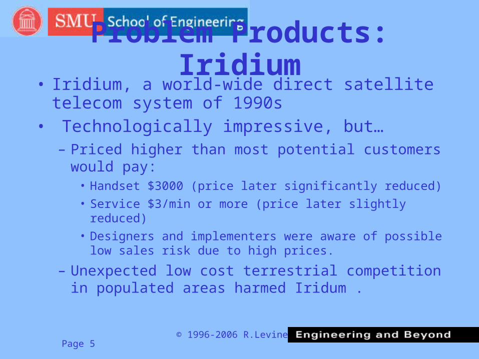
Problem Products: Iridium• Iridium, a world-wide direct satellite telecom
system of 1990s• Technologically impressive, but…
– Priced higher than most potential customers would pay:
• Handset $3000 (price later significantly reduced)
• Service $3/min or more (price later slightly reduced)
• Designers and implementers were aware of possible low sales risk due to high prices.
– Unexpected low cost terrestrial competition in populated areas harmed Iridum .

© 1996-2006 R.LevinePage 6
Iridium: More Recent History• High-budget Customer Base was never large enough:
– For example, oil exploration crews in Siberia? Very few of these!– Native farmers in Kazakhstan? They could not afford Iridium.– Callers from an ocean liner? Sounds promising:
• Existing Inmarsat satellite telephone calls are $10/minute! • But e-mail to/from most ocean liners is free!!
• If you build it, will they come?… Apparently, No!– Customer enrolment was only a tiny fraction of Iridium management’s
estimates. Several top Iridium executives resigned.– Iridium Corp. filed for Chapter 11 bankruptcy protection in August, 1999.
This allows continued operation while a plan is made to hopefully reorganize and eventually pay creditors (bondholders, etc.). Shareholders are not protected in Chapter 11. Reorganized as Iridium Satellite LLC in Dec. 2000
– US Government subscribers are almost the only present users, while Iridium operates in reorganization.
– Development of several competitive LEO satellite systems (e.g. Globalstar) stopped. Licenses were cancelled or returned to the FCC.
© 1996-2006 R.LevinePage 7
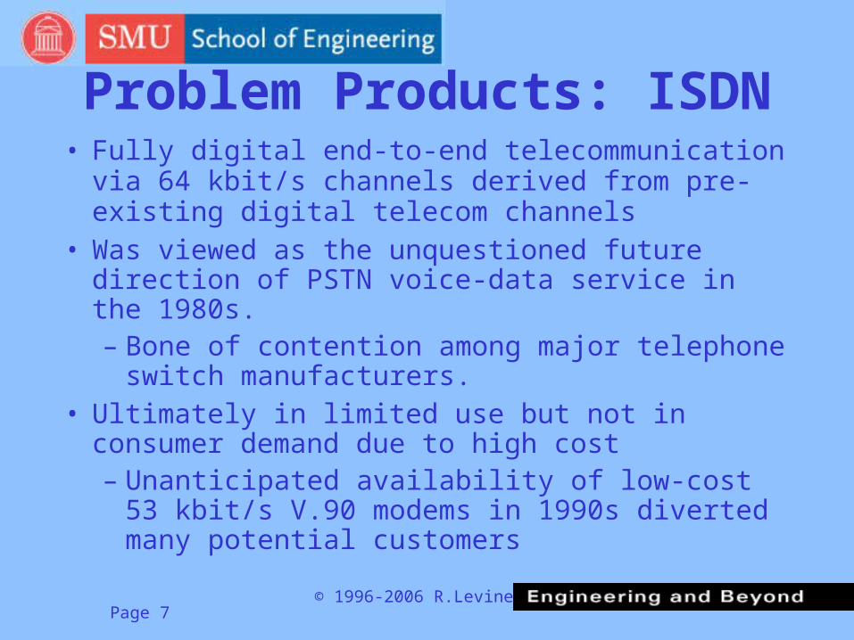
Problem Products: ISDN• Fully digital end-to-end telecommunication via 64
kbit/s channels derived from pre-existing digital telecom channels
• Was viewed as the unquestioned future direction of PSTN voice-data service in the 1980s. – Bone of contention among major telephone
switch manufacturers.• Ultimately in limited use but not in consumer
demand due to high cost– Unanticipated availability of low-cost 53 kbit/s
V.90 modems in 1990s diverted many potential customers
© 1996-2006 R.LevinePage 8
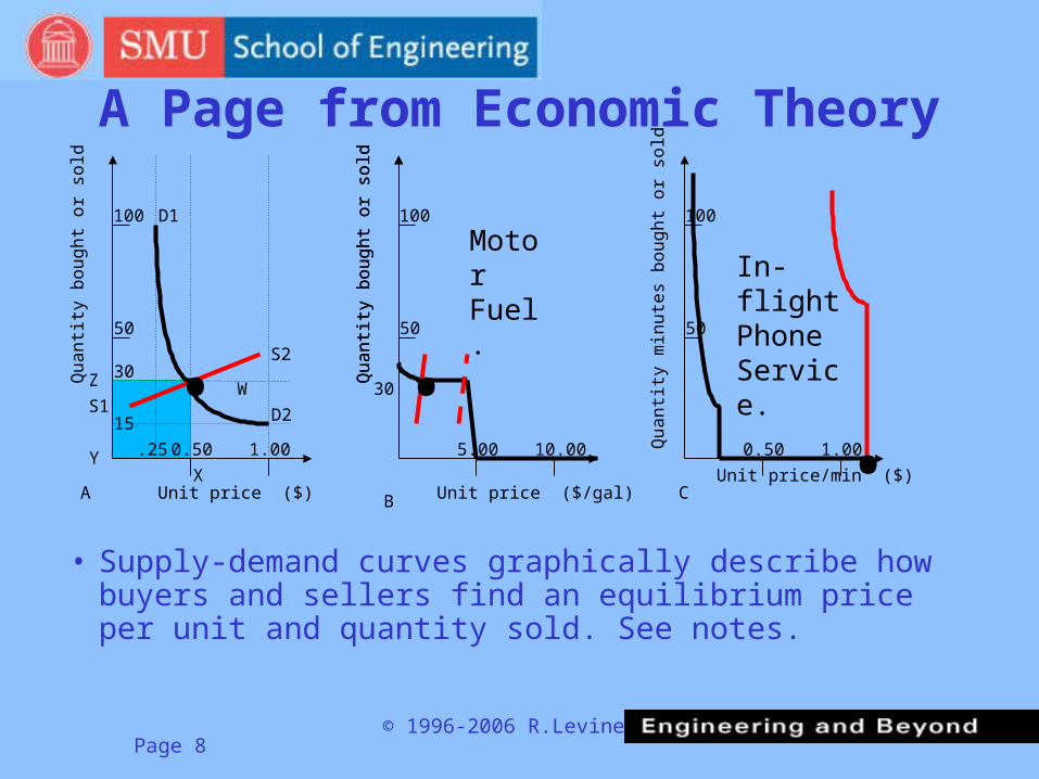
A Page from Economic Theory
• Supply-demand curves graphically describe how buyers and sellers find an equilibrium price per unit and quantity sold. See notes.
Qu
an
tity
bo
ug
ht
or
sold
Unit price ($/gal)
Qu
an
tity
bo
ug
ht
or
sold
0.50 1.00
50
100
Qu
an
tity
bo
ug
ht
or
sold
5.00 10.00
50
100
Qu
an
tity
min
ute
s b
ou
gh
t o
r so
ld
0.50 1.00
50
100
Unit price ($)Unit price/min ($)
A B C
.W
.25
15
30
X
Z
Y
D1
D2
S2
S1 .
In-flight Phone Service.
Motor Fuel.
30 .
© 1996-2006 R.LevinePage 9
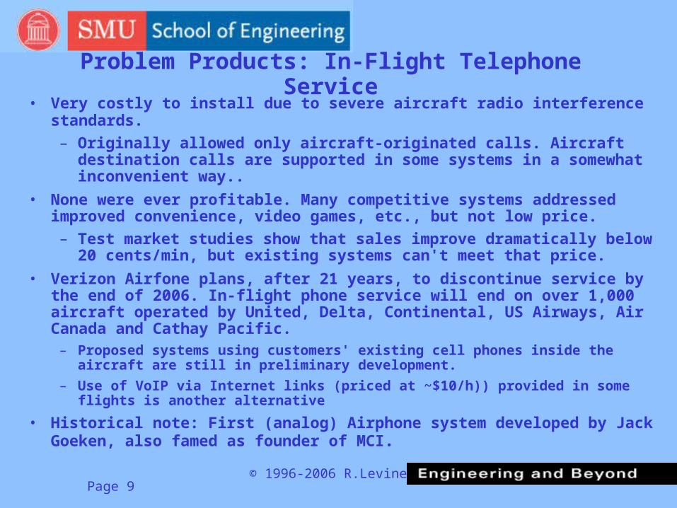
Problem Products: In-Flight Telephone Service• Very costly to install due to severe aircraft radio interference standards.
– Originally allowed only aircraft-originated calls. Aircraft destination calls are supported in some systems in a somewhat inconvenient way..
• None were ever profitable. Many competitive systems addressed improved convenience, video games, etc., but not low price.
– Test market studies show that sales improve dramatically below 20 cents/min, but existing systems can't meet that price.
• Verizon Airfone plans, after 21 years, to discontinue service by the end of 2006. In-flight phone service will end on over 1,000 aircraft operated by United, Delta, Continental, US Airways, Air Canada and Cathay Pacific.
– Proposed systems using customers' existing cell phones inside the aircraft are still in preliminary development.
– Use of VoIP via Internet links (priced at ~$10/h)) provided in some flights is another alternative
• Historical note: First (analog) Airphone system developed by Jack Goeken, also famed as founder of MCI.

© 1996-2006 R.LevinePage 10
Customer Perception of “Fairness” is Important
• Some system proposals did not succeed due to negative customer perception of “fairness”
– Two types of limited play video disks were test marketed circa 1998 as “no return” methods for video rentals. Both rejected by customers.
– System software for wireless air time charges paid by land-line originator were developed, due to industry pressure circa 2000, but 100% of participants in US marketing tests would not choose this billing method.

© 1996-2006 R.LevinePage 11
Concerns about 3G Wireless• Some telecom industry observers fear that 3G, and other advanced wireless
data technologies, will suffer fates like those of Iridium and ISDN.
– First Generation (1G) wireless was analog cellular technology used from1981 to mid 1990s. Very few still in use.
– Second Generation (2G) wireless utilizes digital speech coding, used from early 1990s to the present. Technologies include GSM, CDMA, North American TDMA, iDEN (NexTel) and others. Range of available bit rate per user is about 6 kbit/s to 20 kbit/s
– Two and a Half (2.5G or 2-1/2G) designs are packet data systems, achieving available bit rate per user up to about 60 kbit/s to 140 kbit/s. Used for Internet access and packet voice (VoIP).
– Third Generation (3G) utilizes various types of CDMA (UMTS, CDMA2000). Provides bit rates up to 2 Mbit/s. Major applications are viewing high quality visual entertainment (HDTV images) or possibly transferring massive files via Internet.
– Fourth Generation (4G) utilizes OFDM to achieve 16 Mbit/s or higher bit rates. Applications similar to 3G but even “faster.”
© 1996-2006 R.LevinePage 12
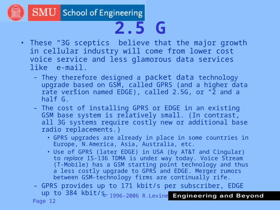
2.5 G• These “3G sceptics” believe that the major growth in cellular
industry will come from lower cost voice service and less glamorous data services like e-mail.– They therefore designed a packet data technology upgrade
based on GSM, called GPRS (and a higher data rate version named EDGE), called 2.5G, or “2 and a half G.”
– The cost of installing GPRS or EDGE in an existing GSM base system is relatively small. (In contrast, all 3G systems require costly new or additional base radio replacements.)
• GPRS upgrades are already in place in some countries in Europe, N.America, Asia, Australia, etc.
• Use of GPRS (later EDGE) in USA (by AT&T and Cingular) to replace IS-136 TDMA is under way today. Voice Stream (T-Mobile) has a GSM starting point technology and thus a less costly upgrade to GPRS and EDGE. Merger rumors between GSM-technology firms are continually rife.
– GPRS provides up to 171 kbit/s per subscriber, EDGE up to 384 kbit/s.

© 1996-2006 R.LevinePage 13
Other Aspects• Previous slides did not analyze or compare:
– Radio bandwidth required for higher bit rates.– Sensitivity of each technology to “noise” and
interference limits the number of simultaneous “conversations” in each cell and thus the system capacity
– Cost and complexity of each technology– Power consumption in active and standby modes,
affecting battery “life.”– An accumulation of negative aspects like these can
severely degrade the theoretical performance of real systems

© 1996-2006 R.LevinePage 14
Customer Preference Issues• In some cases, potential customers won't buy
because they perceive cost or terms of sale inherently unattractive. Examples:
• Today North American wireless subscribers view air time costs over about US$ 0.20/min as excessive
• North American telephone users reject “caller pays” for wireless destination calls (although this is accepted in many other countries).
• In a non-telecom case, customers reject a “self destructing” or “pay per view” video disc.
© 1996-2006 R.LevinePage 15
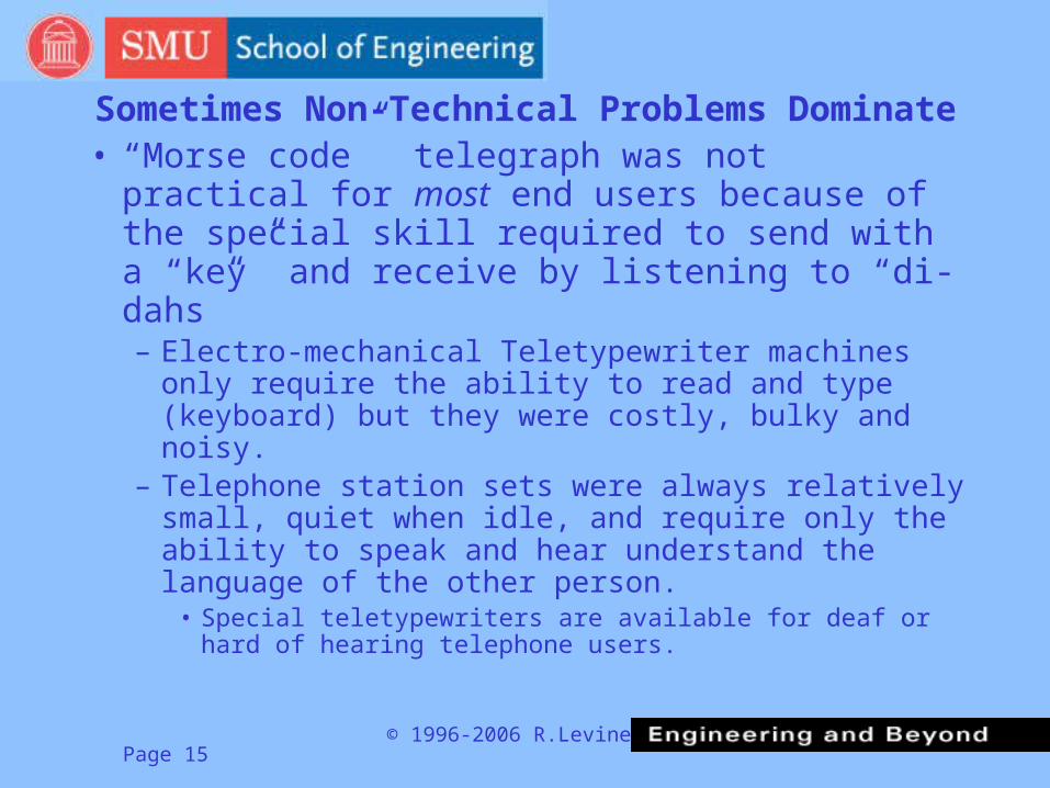
Sometimes Non-Technical Problems Dominate
• “Morse code” telegraph was not practical for most end users because of the special skill required to send with a “key” and receive by listening to “di-dahs”– Electro-mechanical Teletypewriter machines only
require the ability to read and type (keyboard) but they were costly, bulky and noisy.
– Telephone station sets were always relatively small, quiet when idle, and require only the ability to speak and hear understand the language of the other person.
• Special teletypewriters are available for deaf or hard of hearing telephone users.
© 1996-2006 R.LevinePage 16
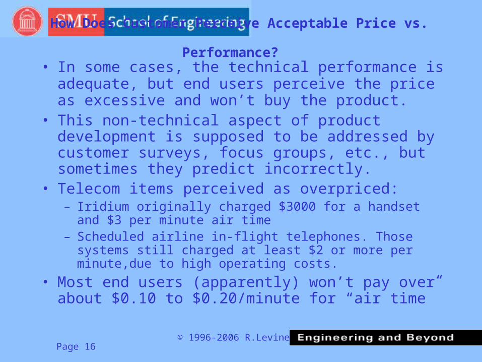
How Does Customer Perceive Acceptable Price vs. Performance? • In some cases, the technical performance is adequate,
but end users perceive the price as excessive and won’t buy the product.
• This non-technical aspect of product development is supposed to be addressed by customer surveys, focus groups, etc., but sometimes they predict incorrectly.
• Telecom items perceived as overpriced:– Iridium originally charged $3000 for a handset and $3 per
minute air time– Scheduled airline in-flight telephones. Those systems still
charged at least $2 or more per minute,due to high operating costs.
• Most end users (apparently) won’t pay over about $0.10 to $0.20/minute for “air time”

© 1996-2006 R.LevinePage 17
Best to Understand Technology Yourself• Make well-founded decisions yourself
– Less dependence on the opinions of others– Your instructor earns most of his income from being a
“technology expert” consultant, but would still rather have his clients understand the technology themselves!
• Separate the wheat from the chaff when exaggerated product claims are made
• Make realistic and profitable product and service plans– Do customers exist for this product or service?– Are they willing to pay a compensatory price for the product
at projected costs?– Why is the product competitively advantageous? What are
the competitive products or services?

© 1996-2006 R.LevinePage 18
Now: Telecom Technology• Having said enough for now about the reasons and
motivations for telecom products, we turn to the technology of telecommunication.
• There are two ways to convey information:– Send a physical object. Historically, the customary object is
a letter (e.g. on papyrus, parchment and later on paper).
– Send some “energy” in the form of an electromagnetic wave. In ancient times, light was involved in viewing signals or semaphore signals at a distance. Privacy and data rate improvements had to wait for the discovery and a minimal understanding of electricity.
© 1996-2006 R.LevinePage 19
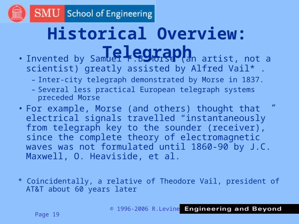
Historical Overview: Telegraph• Invented by Samuel F.B.Morse (an artist, not a scientist)
greatly assisted by Alfred Vail* .– Inter-city telegraph demonstrated by Morse in 1837. – Several less practical European telegraph systems preceded
Morse
• For example, Morse (and others) thought that electrical signals travelled “instantaneously” from telegraph key to the sounder (receiver), since the complete theory of electromagnetic waves was not formulated until 1860-90 by J.C. Maxwell, O. Heaviside, et al.
* Coincidentally, a relative of Theodore Vail, president of AT&T about 60 years later

© 1996-2006 R.LevinePage 20
Telegraph Main Features
• Current flow around a circuit including a battery, telegraph key (on-off switch), a single wire (typically iron, later copper) with the earth as a return path.
• Worked adequately up to about 30 miles, depending on earth conductivity.
• About 1849 the repeater allowed longer links by chaining 30 mi sections via an electro-mechanical “relay” (switching contacts operated by an electromagnet).

© 1996-2006 R.LevinePage 21
Telecom Overview: TelephoneThe telephone was invented in 1876 by Alexander G. Bell
(a speech teacher, not a scientist). Born in Scotland, Bell immigrated to Canada and then the USA.
• The telephone had the significant advantage that no special skill (such as learning Morse code) was required to use it!
– Ease or convenience of use is often a deciding factor in the success of one technology over another.
• Bell’s microphone (called “transmitter”) produced electric current proportional to instantaneous air pressure. Earphone (“receiver”) reversed the process, converting the electrical waveform back into acoustic (sound) form.

© 1996-2006 R.LevinePage 22
Some Business History• Bell was financed by his wealthy industrialist father-in-
law, Gardiner G. Hubbard, a man with a history of business and legal contention with the (then) large Western Union Telegraph Company
• Bell’s original objective was to send several independent telegraph signals over the same circuit– Today we would describe his plan as frequency division
multiplexing (FDM) of amplitude modulated Morse code.
• He discovered by accident that his equipment could transmit speech– He added a new claim to his already filed patent covering this– When the telephone became commercially important, major
patent litigation followed, ultimately decided by the US Supreme Court

© 1996-2006 R.LevinePage 23
Business Conflicts• Bell and Hubbard offered the patent to Western Union
(WU) at first for $100,000– This was an immense sum* in 1876, when a large house cost
less than $1000.– WU turned them down, due to dislike of Hubbard
• A famous negative evaluation letter (probably not authentic) is available on this course web site.
• The letter also is a prime example of– “Not Invented Here” (NIH) attitude, ignoring good outside ideas– Lack of proper appreciation of the advantages of the invention– Inability to accurately foresee that improvements are possible to
overcome the initial disadvantages of the invention
*The Internet web site http://eh.net/ehresources/howmuch/dollarq.php that contains a history of US dollar inflation, indicates that $100,000 in 1876 had the purchasing power of $1,705,922.48 in the year 2005.

© 1996-2006 R.LevinePage 24
Early Competitive Moves• WU, after recognizing the fast growth of the telephone,
quickly decided to get back into competition• They hired the best available inventor, Thomas A.
Edison, to invent a significantly improved microphone circa 1878– Edison studied the telephone, found its most important
weakness, and came up with a solution based on Bell’s “liquid transmitter.” Bell’s liquid transmitter was a variable resistance microphone used in his first working voice transmission, but it was impractical because it used an acid-water solution as the variable resistance material. Edison substituted a sealed capsule of powdered carbon as the pressure sensitive variable resistance element. This “carbon microphone” invention was also later improved by German-American Emil Berliner as well.
© 1996-2006 R.LevinePage 25
Business Strategies• The improvement in audio loudness (permitting longer
telephone wires and thus more wire coverage area per central office) gave the carbon microphone a strong economic competitive advantage.
• But WU could not operate a telephone system without infringing the basic Bell patent, either.
– Negotiations were stalled, until the Bell company suggested something which would be illegal under present anti-trust law…
• WU agreed in 1879 to stay out of the telephone business for 20 years in return for 1% of the income from the telephone.
– The telephone industry grew so fast that Bell was soon able to buy most of WU shares. WU became a subsidiary of Bell from circa 1900 until divested in a famous 1914 anti-trust case.
© 1996-2006 R.LevinePage 26
Early 20th Century• American Telephone & Telegraph (the renamed Bell Telephone
company), was headed for many years by Theodore Vail, coincidentally a nephew of Alfred Vail, Morse’s collaborator.
• Vail vigorously bought out other telephone operating companies in most major cities, leaving only rural areas to the independents (formed after the Bell patents expired). This acquisition stopped in 1914*.
• AT&T purchased Western Electric Co. (electric equipment manufacturer originally so named to save the cost of repainting the entire sign in a former Western Union repair shop), “vertically integrating” manufacturing and telephone operations
• AT&T established its Long Lines division, providing long distance connection between all North American and foreign cities.
*In 1914 AT&T’s negotiator made the “Kingsbury commitment” to not buy out any more independent telephone companies, thus settling a federal antitrust lawsuit.
© 1996-2006 R.LevinePage 27
Some Technological Transmission Advances
• Single wire with earth return was replaced in 1890s by a subscriber “loop” of current carrying copper wire.
– An innovation by J.J.Carty, who became head of AT&T R&D and ultimately established Bell Telephone Laboratories.
Some AT&T accomplishments during the first half of the 20th century:• DeForest’s “Audion” triode vacuum tube amplifier was improved and
adapted for analog voice frequency amplification, leading to coast to coast long distance telephone connections.
• Gilbert S. Vernam invented the Vernam Cipher cryptography method for teletypewriters during WW 1
• The quality and noise of analog telephone connections were improved in 1920s by H.S.Black’s invention of “negative feedback” at Bell Laboratories.
• Frequency Division Multiplexing (FDM) using single side band (SSB) modulation was developed by John R.Carson at Bell Laboratories. Basis of Analog telephone multiplexing.
• Microwave co-ax cable was developed by Lloyd Espenscheid of Bell Labs. Used today for T-3 and other signals.
© 1996-2006 R.LevinePage 28
More Business Developments• The Anti-trust Division of the US Justice Department investigated AT&T in
1914, 1937, 1948, 1965, 1972. Each investigation led to consensual settlements which further restricted the scope of AT&Ts business.
– 1914: “Kingsbury Commitment” stopped acquisition of independent telephone companies and divested WU from AT&T
– 1937: AT&T divested non-telephone businesses (appliances, motion picture sound systems, etc.) and offshore manufacturing.
• ITT (originally International Telephone and Telegraph Corp.) was founded by brothers Sosthenes and Hernand Behn. They were sugar brokers in Porto Rico who first bought the Puerto Rico telephone company. Then they founded Cia. Telefonica Espana in 1923. In 1937, using J.P. Morgan funds, they bought all off-shore Western Electric factories. They later founded other telephone companies in Latin America. ITT sold its telephone manufacturing businesses in 1990s to Alcatel, and now owns hotels, insurance companies and some non-telephone manufacturing firms.
– 1948: AT&T agreed to license all patents to competitors– 1969: AT&T agreed to allow connection of customer-owned equipment (result of
FCC and court CarterPhone decision) rather than renting. AT&T had previously always rented equipment to the subscriber, a method learned from the United Shoe Machinery company in the early Boston years.
– 1984: AT&T divested local telcos (RBOCs) but retained long distance and manufacturing. (Manufacturing later separated under the Lucent name.)
© 1996-2006 R.LevinePage 29
Other Business Events• AT&T, until 1984 divestiture, received 1% of gross income
of all RBOCs– Also was part owner of Bell Canada and Northern Electric, its
manufacturing subsidiary, until 1970s. This became Nortel Networks, no longer owned by AT&T.
– Extensive cross-licensing of patents with other major telephone equipment manufacturers in other countries as well.
• Example: Crossbar telephone switch was developed under cross-licensing agreement with L.M.Ericsson of Sweden
• AT&T acquired NCR (formerly National Cash Register) in 1989, then spun it off as part of the 1996 separation into three businesses. Lucent (with Bell Laboratories) is only a manufacturer and recently merged with Alcatel. AT&T is today an operating company in long distance. Its cellular/PCS activity is a separate corporation, now merged with Cingular Wireless.– Both AT&T and Lucent have started several spin-offs also
© 1996-2006 R.LevinePage 30
Some Major Telecom Vendors with Dallas-Ft.Worth Presence
• Alcatel (France) acquired most ITT manufacturing operations and Rockwell (Collins) telecom products, and Digital Switch Corp. (DSC), and integrated them with its existing products in the 1980-90s.
• Ericsson (Sweden), another long term telecom manufacturer worldwide, has operations here.
• Fujitsu, NEC (Nippon Electric Co.) are two separate independent Japanese telecom manufacturers with Dallas area operations
• Motorola, primarily in Fort Worth (cellular and paging equipment)• Nokia (Finland), strong in cellular/PCS handsets but also makes
cellular infrastructure and landline telecom switchgear• Nortel Networks (formerly Northern Telecom) is a descendant of
Northern Electric of Canada.• Siemens (Germany) a long term telecom and general electrical
equipment maker, now reducing its presence in telecom.This area is sometimes called “Telecom Corridor™” or “Switch Alley”
© 1996-2006 R.LevinePage 31
Some Telephone Operating Companies• Originally 7 (now 4) Regional RBOCs, with
consolidation of SWBell-PacTel-SNET and NYNEX-GTE-Bell Atlantic (now Verizon), etc.
• GTE, arising from mid-century consolidation of many independent local telcos, merged with Bell Atlantic and Primeco wireless to form Verizon (rhymes with horizon) in 2000
• Scattered remaining independents in some smaller cities (e.g. Rochester NY, etc.)
• Numerous Inter-Exchange Carriers (IXCs) the largest 3 being AT&T, MCI and Sprint.
• The government operates Post, Telephone and Telegraph (PTT) administrations in many other countries; but “privatization” is spreading rapidly
© 1996-2006 R.LevinePage 32
Digital Telecom Revolution• The T-1* digital multiplexing system, introduced by Bell Labs in
1961, ultimately led to an almost complete conversion of the North American public switched telephone network (PSTN) to digital transmission and (later) digital switching
• T-1 was a rare and uniquely successful product because it is:– Immediately equal or lower in cost than the prior analog FDM
multiplexer. Cost improved more later with product evolution as well.
– Carefully designed to be backwards compatible with all switching and prior art transmission equipment at connection interfaces
– Better signal quality than FDM multiplex
– More capacity (24 voice channels on the same wires that previously carried only 12 channels)
*Also written T1. Since T-1 is a trade name, DS-1 is an approximately equivalent term used in standards documents, etc.
© 1996-2006 R.LevinePage 33
Is “Digital” Always Better?• The “error” introduced by conversion from analog to digital
representation can be controlled and limited in advance by the designer of the A/D converter. Called “quantizing” error.
• Digital representation of information does not suffer from cumulative “noise” errors. Transmission over a longer distance only causes time delay, not distortion.
– This is the result of a system design in which the two binary digital voltage levels (typically 0 and 5 volts) differ by much more than the typical “noise” voltage level (typically 0.001 volts).
• But… digital representation typically uses more (radio) bandwidth than analog representations.
– This problem can be reduced by use of data compression coding in some cases.
– When the channel is extremely “noisy,” (e.g., a cellular radio link) error protection coding must be used, and this requires part of the total channel bit rate to be devoted to bits for this purpose. Cellular radio systems typically devote half the physical bit rate capacity to error protection.
© 1996-2006 R.LevinePage 34
T-1 Benefited From Prior Technology• PSTN voice signals were historically already low-pass audio-
frequency filtered to attenuate audio power above approx. 3.5 kHz audio frequency
– Necessary for FDM multiplexing and well-verified to support intelligible conversation
– Permits accurate digital waveform coding at 8000 samples/second
• T-1 design was an early application for transistors– Repeaters are installed at 6000 ft. intervals in outdoor or difficult-
access locations and must operate reliably and consume little power– Vacuum tube devices would not be practical
• T-1 uses PCM (pulse code modulation) waveform coding with logarithmic companding
– 8-bit binary coding of each waveform sample, with non-uniform voltage steps, produces uniform signal to noise ratio over a wide range of audio loudness
8 bit/sample • 8000 sample/sec = 64,000 bit/second = 64 kb/s
© 1996-2006 R.LevinePage 35
Incorporation of Call-Processing Signals• Two methods for signaling are in general North American use
1. “Robbed bit” signaling uses the least significant bit of the PCM in every 6th frame to convey supervision (channel busy/idle) status. Five of every six consecutive waveform samples are not affected.
Systems for 12 and 24 multi-frame synchronizing patterns are used to ensure that the signaling equipment uses the proper bit
• Robbed bit signaling leaves 56 kb/s (7 bits of every sample) for the subscriber, even if not multi-frame synchronized
2. Common channel signaling uses a reserved digital channel (either 64 or 1536 kb/s in North America) to convey messages in packet data form between switching systems regarding the call processing on numerous other channels
Common channel signaling system Number 7 is today’s world-wide standard, with some national variants There are many abbreviations: (SS7, CCS7, etc.) In some cases, different abbreviations imply different national variants of Common Channel Number 7.

© 1996-2006 R.LevinePage 36
Further Digital Multiplexing• Higher level digital multiplexing systems were developed with better economy for high
traffic corridors:– T-1 (DS-1): so called North American (and Japan) Primary Rate digital
multiplexing. 24 channels at 1.544 Mb/s– T-1C: a double capacity system (48 channels) now rarely used. Not mentioned in
international standards. 3.152 Mb/s– T-2 (DS-2): a quadruple capacity system (96 channels). Called M12 or
Secondary Rate. Combines 4 DS-1 tributaries. Seldom installed today. 6.312 Mb/s
– T-3 (DS-3): Combines 7 DS-2 tributaries. M13 multiplexers produce this Tertiary level rate from 28 T-1 tributaries. 44.736 Mb/s. Uses co-axial cable or microwaves.
– Different and mostly incompatible “T-4” higher level digital multiplexers using co-axial cable or microwaves were developed in different countries (US, Canada, Japan) but were relatively little used since only a few routes have enough traffic to make this economically feasible.
– European digital multiplexers of similar characteristics are widely used in other countries.

© 1996-2006 R.LevinePage 37
Higher Level Multiplexer Trends• DS-1, DS-2, DS-3 multiplexers are designed to
accommodate small time-varying inaccuracy in the bit rate of the incoming tributaries (plesiochronous multiplexing)
• An undesirably large portion of the total bit rate (bit “overhead”) is needed to handle this, and the necessary process for de-multiplexing a single DS-1 or single 64 kb/s voice channel (DS-0) is complicated and costly
• These difficulties, and the increased use of fiber optic transmission and more accurate digital bit stream synchronization, has led to development of new and fundamentally improved multiplexing designs
© 1996-2006 R.LevinePage 38
EM Wave Transmission Media• Radio transmission. Non-guided via open
space– Inferior channel characteristics due to fading,
interference, etc.– But portability makes cellular service valuable, and
absence of intermediate equipment between microwave towers gives lower cost.
• Guided electromagnetic waves:– Via twisted pair wires, co-axial cable. Typically
using “repeaters” to compensate for signal loss– Via optical fiber, in the infra-red optical frequency
range. Electro-optical or all-optical signal amplifiers are used to compensate for losses.

© 1996-2006 R.LevinePage 39
SONET and SDH• A multiplexing format normally used on optical fiber, but
lowest bit rate members of the family can be transmitted via co-axial cable or microwave radio.– SONET (Synchronous Optical Network) in North America– SDH (Synchronous Digital Hierarchy) elsewhere
• In a refreshing departure from previous international incompatibility, these standards are virtually identical. SONET includes a lowest bit rate version at 51.84 Mb/s which is not used in SDH, but higher rates such as 155.52 Mb/s etc. are common to both standards and are compatible when similarly configured.
© 1996-2006 R.LevinePage 40
Digital Transmission and Switching• The rapid growth of digital multiplexing transmission
systems (almost 100% of the North American network today) led to a parallel development of digital local and long distance switches. These switches are more compact, use less power, and are more reliable than their electro-mechanical predecessors, and mostly contain automatic self-test equipment to permit efficient use of fewer repair personnel
• Digital Switching is now included in the present course EETS8320.

© 1996-2006 R.LevinePage 41
Digital Switch Basics• End office digital switches typically support traditional
analog telephone sets, and in some cases ISDN or proprietary digital telephone sets. The analog voice waveform voltage is periodically measured (“sampled”) and each voltage is converted via analog/digital converters and digitally coded into a bit stream.
• From trunk connections, separate channels of digital information are separated from the bit streams.
• Digital channel data is stored temporarily (typically for 125 microseconds) in a local memory in the switch.
• Desired outgoing channel bit streams are multiplexed together to connect to other switches.
• Microprocessor internal to the switch controls routing of connections.
© 1996-2006 R.LevinePage 42
Switch Types• End-office switch: both trunks and telephone sets
– Formerly called Class 5
• Trunk-trunk switch (no telephone sets)– Used to complete long distance connections between end
switches– Used (with radio base stations) for cellular radio systems– Formerly designated as Class1 to Class 4 based on details
of application in the network.
• Private Branch Exchange (PBX) switches, used primarily for business users to establish both external and internal calls
• “Intercom” switch. Connects telephone sets or “hands-free” stations for internal calls only. Rare today.
© 1996-2006 R.LevinePage 43
Switch Features• All digital switches are microprocessor
controlled and have many features. Some examples:– Call waiting (signal during a conversation that
another caller is attempting to reach you, and ability to answer that caller)
– Incoming call forwarding to another number when desired
– 3-way conference calling via a conference bridge
• PBXs in particular have a large repertoire of sophisticated features.
© 1996-2006 R.LevinePage 44
Digital Speech Coding• A technical “race” has continued for the last quarter
century between speech coding technology and transmission technology– Lower bit rate speech coders are typically more complex
devices, but they allow carrying more conversations in a transmission medium with a fixed total bit rate
– Innovations such as fiber optic transmission and integrated circuits have reduced the cost of high transmission bit rates
• The public telephone industry almost changed over to 32 kb/s ADPCM* speech coding in the early 1980s, but the lower cost of fiber stopped this plan
• Radio systems such as cellular and PCS appear to be the main present use for lower bit rate speech coders.
* Adaptive Differential PCM
© 1996-2006 R.LevinePage 45
Other Speech Coding• Digital speech coding methods generally fall into one of
two categories:1. Waveform coding. Examples include:
– PCM (Mu-law and A-law pulse code modulation: used in DS-1 and E-1)
– ADPCM (adaptive differential PCM - typically 32 kb/s)– Delta Modulation (DM) and CVSD (continuously variable-slope
DM)
2. Audio Power Spectrum Coding. Examples include:– Sub-band coding– RELP (regular - or residual - pulse excited linear predictive coding)– CELP (code excited linear predictive)– VSELP, ACELP (vector sum ELP, Algebraic code ELP)

© 1996-2006 R.LevinePage 46
Some Speech Coder Bit-rates Typical Applications
Lower bit rate coders are generally less satisfactory than higher bit rates.
*PCS= Personal Communications Service, a cellular radio system usually with digital speech coding
Type Bit-rate Applications
Linear Binary PCM 640 kb/s Compact Disk Music
Mu-law, A- law PCM 64 kb/s Telephone
ADPCM 32 kb/s to 16 kb/s Telephone; digital PCS*
DM, CVSD 32 kb/s Military digital communication
Sub-band 32-16 kb/s or lower Some land mobil e and satellites
xELP family 16- 4 kb/s digital cellular and PCS, voice over Internet

© 1996-2006 R.LevinePage 47
Non-voice “Bearer” Services• Due to their near-ubiquitous presence, readily
available investment capital, and the franchise held by many telephone operating companies to install wire, cable or fiber, many other services are also under development and use in the telephone system and related systems
• Images: telefax, video, other images• Data: Internet access, data bases, and related
information• Digital coding of any originally analog information
(such as video) is seen as the optimum method for combined transmission– but verify that the entire system is really advantageous!!
© 1996-2006 R.LevinePage 48
Telephone Data Modems*• Digital data can be transmitted via telephone voice channels
using an audio frequency carrier signal which is modulated to convey binary information by changing its:
– Amplitude (instantaneous voltage or power level). This method is used alone only for Morse Code
– Phase (relative time delay of oscillatory waveform peaks and valleys vis-à-vis a standard “clock” signal)
– Frequency (the quantity of cycles per second; the musical pitch)
• Recent modem (modulator-demodulator) designs mostly use QAM (quadrature amplitude modulation) a combination of amplitude and phase modulation
• V.90 or V.92: In one direction, various voltage amplitude levels are each used to represent a specific 7-bit binary data value.
• ADSL: A special type of multi-carrier QAM modem is used via telephone subscriber wires to carry high bit-rate digital Internet signals in a frequency band above the usual voice frequencies.
* Modem is an invented word made of the first syllables taken from the two words Modulator and DEModulator.
© 1996-2006 R.LevinePage 49
Modem Properties• Data modems today also include automatic equalizers to
compensate for individual voice channel characteristics that would otherwise cause undesired waveform changes.
• Data rates of up to 9.6, 14.4, 28.8 and 33.6 kb/s are feasible using classic adaptive QAM modem technology
• Higher bit rates up to 56 kb/s* use direct PCM encoding at one end
– Fully digital connection at transmitting end. Analog connection at receiving end. Signal voltage can be measured with sufficient accuracy at receiving end to infer the PCM code value used.
– Full 64 kb/s throughput requires a specifically installed digital line such as ISDN or DDS.
* V.90 and V.92 modems today are legally limited to 53 kb/s. The highest voltage levels of PCM are prohibited to avoid “crosstalk” with other wire pairs in the same cables.
© 1996-2006 R.LevinePage 50
Fully Digital Telephone Services• ISDN (integrated services digital network) and
proprietary digital services (DDS, etc.)• Special digital signals used on the subscriber loop• Permits end-to-end 64 or 56 kb/s digital service• For voice, analog-digital conversion is performed in
the ISDN telephone set rather than in the central office switch
• Unfortunately ISDN is very costly, but has had a recent small surge in utilization due to Internet access applications. Some critics view ISDN as an early example of the “Iridium syndrome”
• Emergence of 56 kb/s V.90/92 modems has severely reduced the use of ISDN
© 1996-2006 R.LevinePage 51
Packet Data Systems• In several types of data networks, data is transmitted in “packet”
format– A small block of consecutive data bits from each particular source has a
“header” pre-pended. The header contains, among other things, a code number indicating the destination. This is used to control routing.
– Typically an error-detecting code is appended to the end of the packet.
• In some systems, all packets are the same “size” (length) – in others each packet is of different size, typically based on source data rate.
• Packets from different sources are transmitted via the same channel, one after another
• Most systems use a special “flag” bit pattern, 01111110, as a separator between packets. – The internal packet bit stream is pre-modified (bit stuffing) to exclude
any false occurrences of the”flag pattern.
– At the receiving end, the bit stuffing process is undone
© 1996-2006 R.LevinePage 52
Why Packets?• Many types of digital information sources are “bursty”
in time– Brief “bursts”of high bit rate data are separated by some
time intervals during which no data bits are generated– Data coding methods which remove redundant information
from “raw” speech or video typically produce bursty data
• A number of different packet transmissions can be multiplexed on a shared channel in a high bit rate medium (co-ax, fiber, etc.) more efficiently than using a separate channel for each source, provided that all data sources do not continually produce data bursts simultaneously

© 1996-2006 R.LevinePage 53
ATM (Asynchronous Transfer Mode)• ATM “Payload” data is transmitted in fixed size
packets (called here “cells”) of 48 bytes (384 bits) with a 5 byte identification header (53 bytes total)
• ATM signals can be transmitted e.g. via the “payload” of SONET/SDH at 50 Mb/s or more gross bit rate
• Due to its small packet size, ATM has little signal delay, and is theoretically superior to other packet formats for digitally coded voice.
• ATM is an interesting alternative to LAN/WAN technologies such as Ethernet, although presently far more costly
© 1996-2006 R.LevinePage 54
Telefax (Facsimile,FAX)• Groups 1 and 2 FAX are obsolescent.• Group 3 FAX is in worldwide use. A page image is typically
transmitted in less than a minute at 9.6 kb/s binary data rate via internal modem over a voice grade PSTN channel.
• Group 3 FAX uses binary data compression coding of black/white pixel (or pel) picture elements (“dots”)
– Line difference coding takes advantage of vertical “lines” in the image
– Run-length coding takes advantage of large contiguous areas of white or black, and of long run zero line differences produced by line difference coding.
– Huffman coding takes advantage of repeated appearance of certain binary bit patterns in the FAX bit stream
© 1996-2006 R.LevinePage 55
Other Data Compression Methods• Lossless data compression methods exploit redundant
data bit patterns when present, and accurately regenerate original data when decoded– Plain language text has well-known frequently occurring
characters (E T A O I N etc.) and infrequently occurring characters (J Z Q etc.), a fact that is exploited by Morse code and Huffman coding
– LZW (Lempel-Ziv-Welch) coding dynamically adjusts transmission codes to use short binary patterns for frequent symbols and longer binary patterns for infrequent symbols. LZW is one type of “algebraic” coding.
– Huffman coding is a non-dynamic formal lossless data compression method similar to LZW
© 1996-2006 R.LevinePage 56
Lossy Coding• The word “lossy” implies data compression with imperfect
reconstruction of the original information– Used when human perception can be “fooled,” for:
• Video and still pictures with continuous brightness range (gray or color)
• Audio spectrum (speech) coding. Does not reproduce the exact sound waveform
• Lossy image coding typically approximates the spatial brightness pattern using a family of orthogonal functions– Discrete Cosine Transform is popular for images, video
• Frame difference and motion extrapolation methods are used with video as well
• Video, which requires over 40 Mb/s with simple waveform coding, can be lossy-encoded at 64 to 128 kb/s (via Px64 code) with acceptable (not high) quality and coding delays
© 1996-2006 R.LevinePage 57
Error Protection Coding• Use of additional bits with the “payload” data can be
used to– Correct a limited quantity of bit errors– Detect (but not correct) larger quantity of bit errors
• Error detection codes are often used in conjunction with an Automatic request to Retransmit (ARQ) strategy to retransmit pieces of the data (typically packets) unless they are soon acknowledged as received OK, via a message sent back to transmitter from the receiving end equipment.
• Widely used with error-prone radio channels and delay-tolerant signals such as for wireless call processing messages
• Also used in T-1 extended super frame version, and SONET/SDH multiplexing systems, to continuously monitor transmission accuracy.
© 1996-2006 R.LevinePage 58
Encryption• Important when the transmission is physically open to
interception by unauthorized persons– Particularly for wireless, radio, microwave, etc.
• Encryption methods can also be used to authenticate messages– Only a person who knows the correct “secret key” can properly
encrypt or decrypt a message
• The most widely used physical level encryption method is the Vernam cipher– A “secret” encryption cipher bit stream is “added” to the bits before
transmission, then the same cipher bit stream is “subtracted” out at the receiver*
– The practical complications in this process relate to generating, distributing and synchronizing the cipher bit streams at both the transmit and receive ends.
*Not normal arithmetic addition and subtraction. Rather the XOR, or ring sum or modulo-2 logical operation
© 1996-2006 R.LevinePage 59
End of Lecture 1
• The rest of the sessions involve a more detailed description of the technical topics just listed.