© 2015 ibm corporation bruce powel douglass, ph.d. chief evangelist, global technology ambassador...
TRANSCRIPT

© 2015 IBM Corporation
Bruce Powel Douglass, Ph.D.Chief Evangelist, Global Technology AmbassadorIBM [email protected]: @BruceDouglassIBM: www-01.ibm.com/software/rational/leadership/thought/BruceDouglass.html
Agile Model-Based Systems Engineering (aMBSE)

© 2015 IBM Corporation
State of the Practice for Systems Development
2
Document-centric, not data-centric or verification-centric
Huge investment in planning that doesn’t reflect actual project execution
Not responsive to change
Quality is addressed with expensive and error-prone manual review and update processes
Typically results in long integration and validation cycles
Documents (engineering data) are difficult to manage over the long haul
Regulatory standards compound the problems (e.g. DO0178, EN50128)
Insufficiently addresses system dependability concerns

© 2015 IBM Corporation
Improve quality through continuous feedbackVerification
Formal analysis
Review
Testing via execution or simulation
Validation: Customer feedback (meet the need)
Correctness
Appropriateness
Usability
Dependability: Analysis of safety, reliability, & security
Efficiency throughConcentrate on high-value tasks
Avoid rework
Paying attention to how you’re doing against goals
Project retrospective
Risk management
PlanningDon’t plan beyond the fidelity of the information you have
Plan enough but not more than that
Adjust plans based on “truth on the ground” (metrics)
Key Concepts for Agility
Primarily build executable thingsVerify them continuouslyThis means MODELS
Active and continuous risk mitigationMonitor project success
Dynamic planningResponsive to Change
3

© 2015 IBM Corporation
What does “agile” mean for Systems Engineering?
4
Work iteratively and incrementally
Adjust work tasks and plans to meet business & industry needs
Monitor progress and adjust plans dynamically
Verify work products continuously
Continuously assess safety, reliability, & security
Incrementally update traceability as data stabilizes

© 2015 IBM Corporation
Syntactic Verification
Semantic Verification
Syntactic Verification
– “well-formed” (compliance in form)Performed by quality assurance personnel
• Audits – work tasks are performed as per plan and guidelines
• Syntactic review – work products conform to standard for organization, structure and format
What do we mean by “verification”?
Semantic Verification• “correct” (compliance in meaning)
Performed by engineering personnelThree basic techniques
• Testing – requires executability of work products, impossible to fully verify
• Formal methods – strongest but hard to do and subject to invariant violation
• Semantic review (subject matter expert & peer) – most common, weakest means
5

© 2015 IBM Corporation
Best Practices for Agile Systems Engineering
6
Best Practice
Automatic document generation
Best PracticeOngoing planning for regulatory certification
Best PracticeContinuous verification of SE Work Products
Best PracticeIncremental traceability management
Best PracticeContinuous Dependability Assessment
Best PracticeModel-Based Hand off to Downstream Engineering
Best Practice
High Fidelity Modeling
Best PracticeIncremental Req Definition & Use case Functional Analysis
Best PracticeActive project risk management
Note: a key difference between agile SW and agile SE is that the outcome of SE is specifications and the outcome of SW is implementation

© 2015 IBM Corporation
But Why High-Fidelity Modeling???
Hi-MBE brings to engineering– Precision– Verification via executability or formal methods and the ability to avoid defects in
work products– Stakeholder/Analysis-relevant viewpoints
at any desired level of abstraction e.g.• Functionality• State-based behavior• Algorithmic/control behavior• Structure and Architecture
– Integration of engineering work, e.g.• Functional requirements• Dependability analysis
Safety, reliability, cybersecurity• Architectural structure, behavior, and
allocation• Control modeling and analysis
7
© 2015 IBM Corporation8
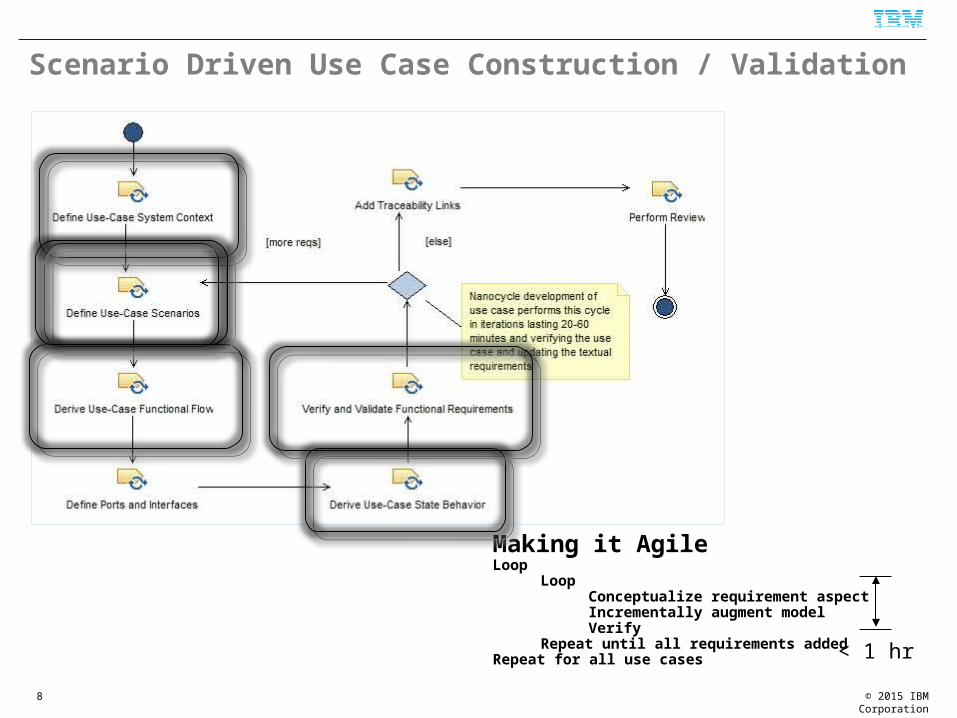
Scenario Driven Use Case Construction / Validation
Making it AgileLoop
LoopConceptualize requirement aspectIncrementally augment modelVerify
Repeat until all requirements addedRepeat for all use cases < 1 hr

© 2015 IBM Corporation
Functional Analysis via Executable Requirements?
• A functional requirement is a specification of an input-output control or data transformation• A quality of service requirements is a specification of how well a control or data
transformation is achieved
Requirement
The system shall perform error correct and detection during initialization and operation.
Requirement
The system shall perform error correct and detection during initialization and operation.
Requirement
The system shall perform error correct and detection during initialization and operation.
Requirement
The system shall be “real good” and “very fast” and “generally awesome”
Requirement
The system shall perform error correct and detection during initialization and operation.
Requirement
The system shall perform error correct and detection during initialization and operation.
Requirement
The system shall perform error correct and detection during initialization and operation.
Requirement
Control surfaces shall be updated every 10 ms +/- 2 ms with an accuracy of .5 cm and a latency of no more than 1 ms
Poor requirements
Much betterrequirements
Requirement
The system shall perform error correct and detection during initialization and operation.
Requirement
The system shall perform error correct and detection during initialization and operation.
Requirement
The system shall perform error correct and detection during initialization and operation.
Requirement
Cyberattcks shall be detected within 10 ms on onset and result in active security measures including incident reports.
9
Requirement
The system shall perform error correct and detection during initialization and operation.
Requirement
The system shall perform error correct and detection during initialization and operation.
Requirement
The system shall perform error correct and detection during initialization and operation.
Requirement
The system shall perform error correct and detection during initialization and operation.

© 2015 IBM Corporation
Test-Driven Development for MBSE Work Products
The principle behind TDD is to develop and apply test cases as you develop a system to demonstrate that it is correct
– This is done in parallel with the system development and not ex post facto– This is about defect avoidance not so much defect identification and repair
TDD applies to the development of complex system use case, architecture and design models
10

© 2015 IBM Corporation
Integrated Safety and Reliability Analysis
11
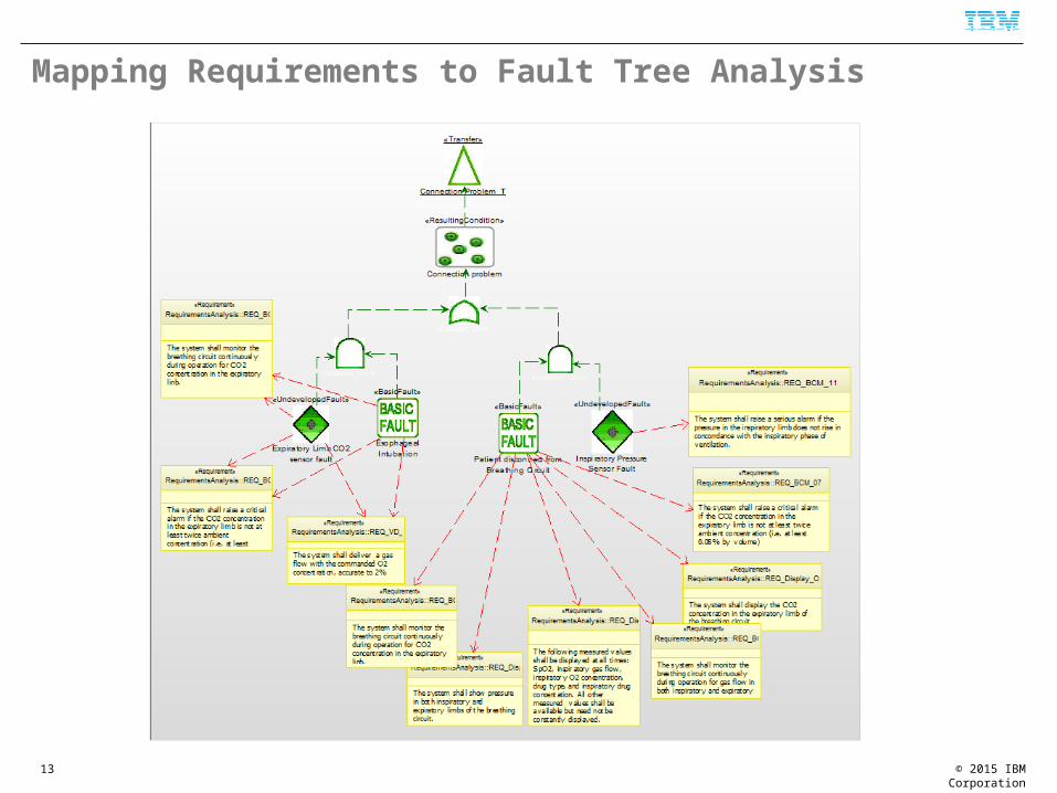
Fault Tree Analysis (FTA) connects hazards with logical combinations of events, conditions, errors, and faults
Allows you to identify Effects of
combinations of conditions and events on safety
Safety measures Safety requirements Impacts of
architectural, technological, and design choices on safety UML FTA
Profile V2

© 2015 IBM Corporation
Integrated Safety and Reliability Analysis
12
© 2015 IBM Corporation
Mapping Requirements to Fault Tree Analysis
13

© 2015 IBM Corporation
Mapping Design to Fault Tree Analysis
14
Fault isolation
Fault detection
Fault control measure

© 2015 IBM Corporation
Model-Based Threat Analysis
Security Analysis Diagram (SAD) is like a Fault Tree Analysis (FTA) but for security, rather than safety
– It looks for the logical relation between assets, vulnerabilities, attacks, and security violations
– Permits reasoning about security
• What kind?• How much?• Risk assessments• Cost of security
penetration• Adequacy of
countermeasures• Who has access to assets
15

© 2015 IBM Corporation
Auto-generation of summary documentation from models
16
Hazard Analysis
Documents are generated automatically from engineering work in models
Typical auto-generated documentation includes Traceability matrix Hazard Analysis FMEA / FMECA Cyberphysical threat analysis table Interface Control Document Design Description Architecture Notebook

© 2015 IBM Corporation
Harmony Agile MBSE Delivery Process
17

© 2015 IBM Corporation
Overall Product Development Workflows: the standard V
18
• Easy to plan• More thorough up-
front analysis makes it applicable for systems with high-risk elements of long lead times (typically HW)
• Plan assumes small number of defects
• Plan assumes little or no change
• Assumes “infinite knowledge”

© 2015 IBM Corporation19
• Relatively easy to plan• Has opportunities to adjust
plans• Supports incremental
verification and release
• Has “dead time” because different people are working on different activities
• May be inappropriate for high-risk items of long lead time (typically hardware)
Overall Product Development Workflows: the fully incremental

© 2015 IBM Corporation
Overall Product Development Workflows: the hybrid agile V
20
• Has opportunities to adjust plans
• Supports incremental verification and release
• Has no “dead time”
• Complex to plan• Requires work to keep
work activities coordinated

© 2015 IBM Corporation
Initiate project
21

© 2015 IBM Corporation
Harmony Process for Agile MBSE
22
© 2015 IBM Corporation
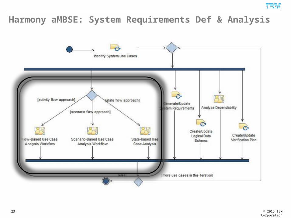
Harmony aMBSE: System Requirements Def & Analysis
23

© 2015 IBM Corporation
Alternative approaches to Build Executable Model of UCAlternative 1:
Scenario Based
Alternative 2:
Flow Based
Alternative 3
State Based
Create model context
Block Diagram Identify functional flow large-scale view
Activity diagram Create Model Context
Block Diagram
Identify sequences of messages between system use case and actors
Sequence Diagram Derive sequences from functional flow
Sequence diagram Create executable state machine
State Diagram
(optional) cluster sequences together as flows
Activity Diagram Create model context
Block Diagram Identify interfaces Block Diagram
Identify interfaces Block Diagram Identify interfaces Block Diagram Derive sequences from functional flow
Sequence diagram
Create executable state machine
State Diagram Create executable state machine
State Diagram Execute State machine
Model execution views
Execute State machine
Model execution views
Execute State machine
Model execution views
Repeat until all requirements and sequence variants covered
Repeat until all requirements and sequence variants covered
Repeat until all requirements and sequence variants covered
24

© 2015 IBM Corporation
Exploring Requirements – Then vs Now
The system shall set Vt in the range of 50 to 1500 ml
The user shall push in the knob to confirm the Vt before the value becomes active
While monitoring, the system will display measured Vt output
Respiration Rate shall be set in the range of 2 – 100 b/m
The user shall push in the Rate knob to confirm the Rate value before it becomes active
Neonate mode shall support Vt from 50 to 500 ml
…
25
Questions What happens if the user turns the Vt knob and then turns
the Rate knob before pushing in to confirm?
How to I abort a Vt change once started?
What happens if the user tries to set the Vt to 1500 and the system is configured for neonates?

© 2015 IBM Corporation
The Traditional Option
Search through the (hundreds to thousands of) requirements to find the one that answers the question
Once you’ve determined that it isn’t in the spec, go back to the stakeholder(s) and ask then what you should do
Or make up something that seems reasonable
26

© 2015 IBM Corporation
Executable Requirements Models
27
Benefits• Ability to explore and evaluate
requirements• Improve ability to identify
requirement defects:• Missing requirements• Incomplete requirements• Conflicting requirements
• Provides facilities to do “what about this …?” analysis
• Reliably results in better requirements

© 2015 IBM Corporation
The Modeling Option
28
© 2015 IBM Corporation
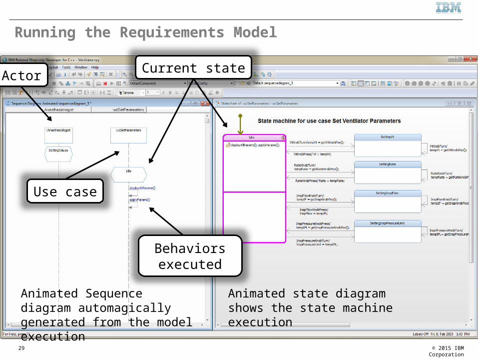
Running the Requirements Model
29
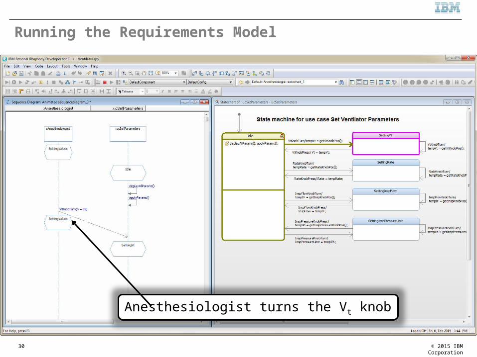
Animated Sequence diagram automagically generated from the model execution
Animated state diagram shows the state machine execution
Current state
Actor
Use case
Behaviors executed
© 2015 IBM Corporation
Running the Requirements Model
30
Anesthesiologist turns the Vt knob

© 2015 IBM Corporation
Running the Requirements Model
31
Anesthesiologist turns the Vt knob more …

© 2015 IBM Corporation
Running the Requirements Model
32
Anesthesiologist turns the Rate knob without confirming – the event is ignored

© 2015 IBM Corporation
Running the Requirements Model
33
Anesthesiologist pushes in the Vt knob

© 2015 IBM Corporation
Logical Data Schema Modeling A logical data schema identifies the logical properties of important data elements and types and
the relations among such data elements and their metadata
Although the name is “data schema” it includes physical, materiel, and energy flows specification as well
34

© 2015 IBM Corporation
Systems Architectural Analysis
35

© 2015 IBM Corporation
Systems Architectural Analysis
36

© 2015 IBM Corporation
Example: SysML Parametric Diagram for Trades
37
Compute MOEs from utility curves
Analyze trades of different solutions

© 2015 IBM Corporation
Outputs of the trade analysis
38

© 2015 IBM Corporation
Architectural Design
39

© 2015 IBM Corporation
Activity: Allocate Use Cases to Subsystems
40

© 2015 IBM Corporation
Architecture View for Control Flow (UML & SysML 1.2)
41
Standard port
Flow port

© 2015 IBM Corporation
Architecture View for Control Flow (SysML 1.3)
42
Proxy ports are typed by Interface Blocks
Interface Block
Interface Block

© 2015 IBM Corporation
Capturing ICDs in the Model
ICDs are not just a list of services but include:– For each Service
• Functional Description• Preconditions• Postconditions• Invariants• Performance• Error handling• Synchronization type• For each parameter
Description
Type
Units
Valid subrange
Default value
This metadata can be easily added as tags defined in stereotypes
43

© 2015 IBM Corporation
Capturing ICDs in the Model
44
Use flow ports for continuous value interfacesUse standard ports for discrete interfaces (events and calls)

© 2015 IBM Corporation
Hand off Workflow
45
Hand off elements common to
multiple subsystems to the
shared model
Hand off specification elements to individual
subsystems
Allocate requirements to
engineering disciplines

© 2015 IBM Corporation
You’re Agile, but are you Meta-Agile?Using Agile to Adopt Agile MBSE
46
Architect
Plan
Pilot
Enact
Assess
Determine organizational objectives
Discover as-is processIdentify issues & problems
Determine goal-as-is gapIdentify future needsDefine to-be process, practices, and tools
Define steps to incrementally adopt
Specific metrics to dynamically measure on-
going success
Enact in a small controlled project
Measure successAdapt approach based on
evidence
Phase deployment of plan into the
enterprise, including training, mentoring
and metrics

© 2015 IBM Corporation
Summary
47
MBSE provides precision and
verifiability to the SE Process
Agile methods add quality, responsiveness and adaptability to the
process
Continuous verification allows you to avoid
costly defects
IBM’s Harmony Process defines an agile MBSE
process with industry best practices IBM’s Rational tooling
supports MBSE and agile methods
Adopt Agile in an incremental, measured fashion for best results

© 2015 IBM Corporation
References
48