********************************************************** 34 41 26.00 10.pdf · access control...
TRANSCRIPT

**************************************************************************USACE / NAVFAC / AFCEC / NASA UFGS 34 41 26. 00 10 ( Febr uar y 2009) - - - - - - - - - - - - - - - - - - - - - - - - - - - - - - - - - - -Pr epar i ng Act i v i t y: USACE Super sedi ng UFGS 34 41 26. 00 10 ( Apr i l 2008)
UNI FI ED FACI LI TI ES GUI DE SPECI FI CATI ONS
Ref er ences ar e i n agr eement wi t h UMRL dat ed Apr i l 2018**************************************************************************
SECTI ON TABLE OF CONTENTS
DI VI SI ON 34 - TRANSPORTATI ON
SECTI ON 34 41 26. 00 10
ACCESS CONTROL POI NT CONTROL SYSTEM
02/09
PART 1 GENERAL
1. 1 REFERENCES 1. 2 ACRONYM LI ST 1. 3 SYSTEM DESCRI PTI ON 1. 3. 1 Desi gn St r at egy 1. 3. 1. 1 Det ect i on 1. 3. 1. 2 Depl oy t he Bar r i er 1. 3. 1. 3 Del ay 1. 3. 2 Over - speed and Wr ong- Way Sensor s 1. 3. 2. 1 Poi nt Over Speed 1. 3. 2. 2 Cont i nuous Over Speed Det ect i on - One Zone 1. 3. 2. 3 Cont i nuous Over Speed Det ect i on - Two Zones 1. 3. 2. 4 Wr ong Way Det ect i on 1. 3. 3 Act i ve Vehi c l e Bar r i er Saf et y Syst em 1. 4 SUBMI TTALS 1. 5 QUALI TY ASSURANCE 1. 5. 1 Pr oj ect Manager Qual i f i cat i ons 1. 5. 2 I nst al l at i on Super i nt endent Qual i f i cat i ons 1. 5. 3 QC Repr esent at i ve Qual i f i cat i ons 1. 5. 4 Techni cal Speci al i s t s Qual i f i cat i ons 1. 5. 5 Li ne Super vi s i on 1. 5. 5. 1 Gener al 1. 5. 5. 2 Dat a Tr ansmi ssi on Syst em ( DTS) 1. 6 DELI VERY OF TECHNI CAL DATA AND COMPUTER SOFTWARE 1. 6. 1 Gr oup I Techni cal Dat a Package 1. 6. 2 Gr oup I I Techni cal Dat a Package 1. 6. 3 Gr oup I I I Techni cal Dat a Package 1. 6. 4 Gr oup I V Techni cal Dat a Package 1. 6. 4. 1 Act i ve Vehi c l e Bar r i er Cont r ol s 1. 6. 4. 2 Over - speed and Wr ong- way det ect i on 1. 6. 4. 3 Tr af f i c Cont r ol Pl an f or t he Mai nt enance of Tr af f i c Dur i ng
Construction 1. 6. 4. 4 Tr af f i c Cont r ol Pl an Dur i ng Act i ve Vehi c l e Bar r i er
Maintenance 1. 6. 4. 5 Appl i cat i on Sof t war e
SECTI ON 34 41 26. 00 10 Page 1

1. 6. 4. 6 Sof t war e Manual 1. 6. 4. 7 Har dwar e Manual 1. 6. 4. 8 Funct i onal Desi gn Manual 1. 6. 4. 9 Mai nt enance Manual 1. 6. 4. 10 Tr ai ni ng Document at i on 1. 6. 4. 11 Dat a Ent r y 1. 6. 5 Gr oup V Techni cal Dat a Package 1. 6. 5. 1 Gr oup I V Manual s 1. 6. 5. 2 Fi nal Syst em Dr awi ngs 1. 7 WARRANTY 1. 8 MAI NTENANCE AND SERVI CE 1. 8. 1 Descr i pt i on of Wor k 1. 8. 2 Ser v i ce Per sonnel 1. 8. 3 Schedul e of Wor k 1. 8. 3. 1 Mi nor I nspect i ons 1. 8. 3. 2 Maj or I nspect i ons 1. 8. 3. 3 Schedul ed Wor k 1. 8. 4 Emer gency Ser vi ce 1. 8. 5 Oper at i on 1. 8. 6 Recor ds and Logs 1. 8. 7 Wor k Request s 1. 8. 8 Syst em Modi f i cat i ons 1. 8. 9 Sof t war e
PART 2 PRODUCTS
2. 1 MATERI ALS 2. 1. 1 Mat er i al s and Equi pment 2. 1. 2 Fi el d Encl osur es 2. 1. 2. 1 I nt er i or Sensor s 2. 1. 2. 2 Ext er i or Sensor s 2. 1. 2. 3 I nt er i or El ect r oni cs 2. 1. 2. 4 Ext er i or El ect r oni cs 2. 1. 2. 5 Cor r osi on Resi st ant 2. 1. 3 Namepl at es 2. 1. 4 Tamper Swi t ches 2. 1. 5 Locks and Key- Lock Swi t ches 2. 1. 5. 1 Locks 2. 1. 5. 2 Key- Lock- Oper at ed Swi t ches 2. 1. 5. 3 Const r uct i on Locks 2. 1. 6 Syst em Component s 2. 1. 6. 1 Modul ar i t y 2. 1. 6. 2 Mai nt ai nabi l i t y 2. 1. 6. 3 I nt er changeabi l i t y 2. 1. 6. 4 Pr oduct Saf et y 2. 1. 7 Cont r ol s and Desi gnat i ons 2. 1. 8 Syst em I nt egr at i on 2. 1. 9 Envi r onment al Condi t i ons 2. 1. 9. 1 I nt er i or Condi t i ons 2. 1. 9. 1. 1 [ Ent er Appr opr i at e Subpar t Ti t l e Her e] 2. 1. 9. 1. 2 Pr essur e 2. 1. 9. 1. 3 Rel at i ve Humi di t y 2. 1. 9. 1. 4 Fungus 2. 1. 9. 1. 5 Acoust i cal Noi se 2. 1. 9. 2 Ext er i or Condi t i ons 2. 1. 9. 2. 1 Temper at ur e 2. 1. 9. 2. 2 Pr essur e 2. 1. 9. 2. 3 Sol ar Radi at i on 2. 1. 9. 2. 4 Sand and Dust
SECTI ON 34 41 26. 00 10 Page 2

2. 1. 9. 2. 5 Rai n 2. 1. 9. 2. 6 Humi di t y 2. 1. 9. 2. 7 Fungus 2. 1. 9. 2. 8 Sal t Fog 2. 1. 9. 2. 9 Snow 2. 1. 9. 2. 10 I ce Accr et i on 2. 1. 9. 2. 11 Wi nd 2. 1. 9. 2. 12 Acoust i cal Noi se 2. 2 ACTI VE VEHI CLE BARRI ER CONTROL SYSTEM ( AVBCS) 2. 2. 1 Gener al Requi r ement s 2. 2. 2 AVBCS Pr ocessor 2. 2. 3 Ti mi ng Requi r ement s 2. 2. 4 Conf l i c t Moni t or 2. 2. 5 Conf i gur at i on 2. 2. 6 Communi cat i ons 2. 3 TRAFFI C CONTROLLER UNI T ( TCU) PROCESSI NG AND CONTROL SOFTWARE 2. 3. 1 Load and Adj ust Sof t war e 2. 3. 2 Di spl ay I nf or mat i on 2. 3. 3 TCU Ut i l i t y Pr ogr ammi ng 2. 3. 4 Command Sof t war e 2. 3. 5 Command I nput and Er r or s 2. 3. 6 Speci al Funct i ons 2. 3. 6. 1 Hel p 2. 3. 6. 2 St ar t / Enabl e 2. 3. 6. 3 St op/ Di sabl e 2. 3. 6. 4 Dynami c Di spl ays 2. 3. 6. 5 Aut o/ Over r i de 2. 3. 6. 6 Pr i nt Repor t 2. 3. 7 Syst em Access Cont r ol 2. 3. 8 Al ar ms 2. 3. 9 Repor t Gener at or 2. 3. 10 Per i odi c Aut omat i c Repor t 2. 3. 11 ACP Pr ocessi ng and Cont r ol Dat abase 2. 3. 12 Dat abase Def i ni t i on Pr ocess 2. 3. 13 Hi st or i cal Dat a St or age and Ret r i eval 2. 3. 14 Secur i t y Management 2. 4 GATEHOUSE CONTROL CONSOLE ( GCC) 2. 4. 1 Al ar m Di spl ay 2. 4. 2 Over speed and Wr ong Way Annunci at i on Panel s 2. 4. 3 CCTV Moni t or and Cont r ol s 2. 4. 4 Act i ve Vehi c l e Bar r i er Cont r ol s 2. 5 ALARM DI SPLAY I N THE GCC 2. 6 SEQUENCE OF EVENTS RECORDER 2. 7 ALARM PANELS AT THE GUARD BOOTHS 2. 8 GUARD BOOTH AND OVERWATCH POSI TI ON CONTROL PANELS 2. 9 CCTV SYSTEM 2. 10 UNI NTERRUPTI BLE POWER SUPPLI ES ( UPS) 2. 11 OVER SPEED, WRONG- WAY, AND VEHI CLE PRESENCE DETECTORS 2. 11. 1 Phot oel ect r i c Type 2. 11. 2 I nduct i on Loops 2. 11. 3 Radar 2. 11. 4 Vi deo Det ect i on 2. 12 BALANCED MAGNETI C SWI TCH ( BMS) 2. 12. 1 BMS Subassembl i es 2. 12. 2 Housi ng 2. 12. 3 Remot e Test 2. 12. 4 Access/ Secur e 2. 13 DURESS ALARMS 2. 13. 1 Foot - r ai l
SECTI ON 34 41 26. 00 10 Page 3

2. 13. 2 Push- but t on 2. 13. 3 Wi r el ess 2. 14 ACTUATED TRAFFI C ARMS 2. 14. 1 Tr af f i c Ar m Assembl y 2. 14. 2 Pr esence Det ect i on Saf et y Syst em Onl y 2. 15 TRAFFI C SI GNALS 2. 16 WARNI NG BEACONS 2. 17 TRAFFI C SI GNAL SUPPORTS 2. 18 ACTI VE VEHI CLE BARRI ERS 2. 19 SI GNS AND PAVEMENT MARKI NGS 2. 20 WI RE AND CABLE 2. 20. 1 Above Gr ound Sensor Wi r i ng 2. 20. 2 Di r ect Bur i al Sensor Wi r i ng 2. 20. 3 Cabl e Const r uct i on 2. 21 POWER LI NE SURGE PROTECTI ON 2. 21. 1 Sensor Devi ce Wi r i ng and Communi cat i on Ci r cui t Sur ge Pr ot ect i on 2. 21. 2 Power Li ne Condi t i oner s 2. 22 FACTORY ACCEPTANCE TEST 2. 22. 1 Gener al 2. 22. 2 Test Pl an 2. 22. 3 Test 2. 22. 4 Test Repor t
PART 3 EXECUTI ON
3. 1 EXAMI NATI ON 3. 2 I NSTALLATI ON 3. 2. 1 Over si ght 3. 2. 2 I nst al l at i on Schedul e 3. 2. 3 Wi r i ng 3. 2. 4 Gr oundi ng 3. 2. 5 Encl osur e Penet r at i ons 3. 2. 6 Col d Gal vani z i ng 3. 2. 7 Ot her Requi r ement s 3. 2. 8 I nci dent al I nf r ast r uct ur e 3. 3 CONTRACTOR FI ELD TEST 3. 4 COMMI SSI ONI NG 3. 4. 1 Gener al 3. 4. 2 Commi ssi oni ng Team Leader 3. 4. 3 Commi ssi oni ng Team 3. 4. 4 Tr ai ni ng 3. 4. 4. 1 Gener al Requi r ement s 3. 4. 4. 2 Guar d' s Tr ai ni ng 3. 4. 4. 3 Mai nt enance Per sonnel Tr ai ni ng 3. 4. 4. 4 Syst em Manager Tr ai ni ng 3. 4. 5 Per f or mance Ver i f i cat i on Test ( PVT) 3. 4. 5. 1 Test Pl an 3. 4. 5. 2 Test Equi pment 3. 4. 5. 3 Test 3. 4. 5. 4 Test Repor t 3. 4. 5. 5 Opposi t e Season Test 3. 4. 6 Endur ance Test 3. 4. 6. 1 Gener al 3. 4. 6. 2 Phase I Test i ng 3. 4. 6. 3 Phase I I Assessment 3. 4. 6. 4 Phase I I I Test i ng 3. 4. 6. 5 Phase I V Assessment 3. 4. 7 Commi ssi oni ng Repor t 3. 5 APPENDI CES
SECTI ON 34 41 26. 00 10 Page 4

ATTACHMENTS:
Appendi x A
- - End of Sect i on Tabl e of Cont ent s - -
SECTI ON 34 41 26. 00 10 Page 5

**************************************************************************USACE / NAVFAC / AFCEC / NASA UFGS 34 41 26. 00 10 ( Febr uar y 2009) - - - - - - - - - - - - - - - - - - - - - - - - - - - - - - - - - - -Pr epar i ng Act i v i t y: USACE Super sedi ng UFGS 34 41 26. 00 10 ( Apr i l 2008)
UNI FI ED FACI LI TI ES GUI DE SPECI FI CATI ONS
Ref er ences ar e i n agr eement wi t h UMRL dat ed Apr i l 2018**************************************************************************
SECTI ON 34 41 26. 00 10
ACCESS CONTROL POI NT CONTROL SYSTEM02/09
**************************************************************************NOTE: Thi s speci f i cat i on cover s t he r equi r ement s f or t he desi gn of an access cont r ol poi nt cont r ol system.
Adher e t o UFC 1- 300- 02 Uni f i ed Faci l i t i es Gui de Speci f i cat i ons ( UFGS) For mat St andar d when edi t i ng t hi s gui de speci f i cat i on or pr epar i ng new pr oj ect speci f i cat i on sect i ons. Edi t t hi s gui de speci f i cat i on f or pr oj ect speci f i c r equi r ement s by addi ng, del et i ng, or r evi s i ng t ext . For br acket ed i t ems, choose appl i cabl e i t em( s) or i nser t appr opr i at e i nf or mat i on.
Remove i nf or mat i on and r equi r ement s not r equi r ed i n r espect i ve pr oj ect , whet her or not br acket s ar e present.
Comment s, suggest i ons and r ecommended changes f or t hi s gui de speci f i cat i on ar e wel come and shoul d be submi t t ed as a Cr i t er i a Change Request ( CCR) .
**************************************************************************
PART 1 GENERAL
**************************************************************************NOTE: The desi gn of an ACP must be f ul l y engi neer ed t o ensur e compl i ance wi t h t he Ar my St andar ds f or ACPs, t he Of f i ce of t he Pr ovost Mar shal Gener al ' s Cr i t er i a f or ACPs, and t he St andar d Def i ni t i ve Desi gn f or ACPs. Usi ng t hese st andar ds and cr i t er i a, t he desi gner must pr epar e an ACP pr oj ect speci f i c desi gn i ncl udi ng t he dr awi ngs as i ndi cat ed her ei n. The pr oj ect speci f i c dr awi ngs al ong wi t h t hi s edi t ed per f or mance speci f i cat i on must be i ncl uded i n t he pr ocur ement document s f or t he Access Cont r ol Poi nt Cont r ol Syst em.
Dr awi ngs must i dent i f y t he f ol l owi ng: act i ve and passi ve vehi c l e bar r i er l ocat i ons, over - speed and wr ong way det ect i on zones, Cl osed Ci r cui t Tel evi s i on
SECTI ON 34 41 26. 00 10 Page 6

( CCTV) camer a cover age ar eas, I nt r usi on Det ect i on Sensor l ocat i ons, t r af f i c s i gnal and war ni ng beacon l ocat i ons, act uat ed gat e ar m l ocat i ons, and i nci dent al const r uct i on. Al so, i ncl ude act i ve bar r i er cont r ol panel s and cont r ol schemat i cs.
ACP St andar d Def i ni t i ve Desi gn St andar d Dr awi ng E1. 03 can be used f or r equi r ed cont r ol panel s, and appr opr i at e dr awi ng among dr awi ngs E1. 04 t hr ough E1. 06 can be used f or t he cont r ol schemat i c. However , i f changes t o t he cont r ol panel s f r om dr awi ng E1. 03 ar e made, t he desi gner i s r esponsi bl e f or changi ng t he cont r ol schemat i c ( dr awi ng E1. 04, 5, or 6) t o pr ovi de t he secur i t y and saf et y measur es r equi r ed i n t he Ar my St andar d f or ACPs.
**************************************************************************
1. 1 REFERENCES
**************************************************************************NOTE: Thi s par agr aph i s used t o l i s t t he publ i cat i ons c i t ed i n t he t ext of t he gui de speci f i cat i on. The publ i cat i ons ar e r ef er r ed t o i n t he t ext by basi c desi gnat i on onl y and l i s t ed i n t hi s par agr aph by or gani zat i on, desi gnat i on, dat e, and t i t l e.
Use t he Ref er ence Wi zar d' s Check Ref er ence f eat ur e when you add a Ref er ence I dent i f i er ( RI D) out s i de of t he Sect i on' s Ref er ence Ar t i c l e t o aut omat i cal l y pl ace t he r ef er ence i n t he Ref er ence Ar t i c l e. Al so use t he Ref er ence Wi zar d' s Check Ref er ence f eat ur e t o updat e t he i ssue dat es.
Ref er ences not used i n t he t ext wi l l aut omat i cal l y be del et ed f r om t hi s sect i on of t he pr oj ect speci f i cat i on when you choose t o r econci l e r ef er ences i n t he publ i sh pr i nt pr ocess.
**************************************************************************
The publ i cat i ons l i s t ed bel ow f or m a par t of t hi s speci f i cat i on t o t he ext ent r ef er enced. The publ i cat i ons ar e r ef er r ed t o wi t hi n t he t ext by t he basi c desi gnat i on onl y.
AMERI CAN ASSOCI ATI ON OF STATE HI GHWAY AND TRANSPORTATI ON OFFI CI ALS (AASHTO)
AASHTO GDHS- 5 ( 2011, Er r at a 2012) A Pol i cy on Geomet r i c Desi gn of Hi ghways and St r eet s
AASHTO LTS ( 2013; Er r at a 2013) St andar d Speci f i cat i ons f or St r uct ur al Suppor t s f or Hi ghway Si gns, Lumi nai r es and Tr af f i c Signals
AASHTO RSDG- 4 ( 2011; Er r at a 1 2012; Er r at a 2 2015) Roadsi de Desi gn Gui de
SECTI ON 34 41 26. 00 10 Page 7

I NSTI TUTE OF ELECTRI CAL AND ELECTRONI CS ENGI NEERS ( I EEE)
I EEE 142 ( 2007; Er r at a 2014) Recommended Pr act i ce f or Gr oundi ng of I ndust r i al and Commer ci al Power Syst ems - I EEE Gr een Book
I EEE 802. 3 ( 2015; CORR 2017; AMD 1 2017) Et her net
I EEE C62. 41. 1 ( 2002; R 2008) Gui de on t he Sur ges Envi r onment i n Low- Vol t age ( 1000 V and Less) AC Power Ci r cui t s
I EEE C62. 41. 2 ( 2002) Recommended Pr act i ce on Char act er i zat i on of Sur ges i n Low- Vol t age ( 1000 V and Less) AC Power Ci r cui t s
I NSTI TUTE OF TRANSPORTATI ON ENGI NEERS ( I TE)
I TE ATC 5201 ( 2006; v5. 2b) Advanced Tr anspor t at i on Cont r ol l er ( ATC) St andar d
I NTERNATI ONAL ELECTROTECHNI CAL COMMI SSI ON ( I EC)
I EC 60068- 2- 27 ( 2008; ED 4. 0) Envi r onment al Test i ng - Par t 2- 27: Test s - Test Ea and Gui dance: Shock
I EC 60068- 2- 30 ( 2005; ED 3. 0) Envi r onment al Test i ng - Par t 2- 30: Test s - Test Db: Damp Heat , Cycl i c ( 12 H + 12 H Cycl e)
I EC 61000- 4- 5 ( 2017) El ect r omagnet i c Compat i bi l i t y ( EMC) - Par t 4- 5: Test i ng and Measur ement Techni ques - Sur ge I mmuni t y Test
NATI ONAL ELECTRI CAL MANUFACTURERS ASSOCI ATI ON ( NEMA)
NEMA 250 ( 2014) Encl osur es f or El ect r i cal Equi pment ( 1000 Vol t s Maxi mum)
NEMA I CS 1 ( 2000; R 2015) St andar d f or I ndust r i al Cont r ol and Syst ems: Gener al Requi r ement s
NEMA TS- 1 ( 1989; R 2005) Tr af f i c Cont r ol Syst ems ( not r ecommended f or new desi gns)
NEMA TS- 2 ( 2016) Tr af f i c Cont r ol l er Assembl i es wi t h NTCI P Requi r ement s - Ver si on 03. 07
NATI ONAL FI RE PROTECTI ON ASSOCI ATI ON ( NFPA)
NFPA 70 ( 2017; ERTA 1- 2 2017; TI A 17- 1; TI A 17- 2; TI A 17- 3; TI A 17- 4; TI A 17- 5; TI A 17- 6; TI A 17- 7; TI A 17- 8; TI A 17- 9; TI A 17- 10; TI A 17- 11; TI A 17- 12; TI A 17- 13; TI A 17- 14) Nat i onal El ect r i cal Code
SECTI ON 34 41 26. 00 10 Page 8

U. S. ARMY ( DA)
DA AR 55- 80 ( 2003) DOD Tr anspor t at i on Engi neer i ng Program
U. S. ARMY CORPS OF ENGI NEERS ( USACE)
EM 385- 1- 1 ( 2014) Saf et y and Heal t h Requi r ement s Manual
U. S. FEDERAL HI GHWAY ADMI NI STRATI ON ( FHWA)
MUTCD ( 2015) Manual on Uni f or m Tr af f i c Cont r ol Devices
NCHRP 350 ( 1993) Recommended Pr ocedur es f or t he Saf et y Per f or mance Eval uat i on of Hi ghway Features
U. S. NATI ONAL ARCHI VES AND RECORDS ADMI NI STRATI ON ( NARA)
21 CFR 1040 Per f or mance St andar ds f or Li ght - Emi t t i ng Products
UNDERWRI TERS LABORATORI ES ( UL)
UL 1076 ( 1995; Repr i nt Mar 2015) Pr opr i et ar y Bur gl ar Al ar m Uni t s and Syst ems
UL 796 ( 2016) UL St andar d f or Saf et y Pr i nt ed- Wi r i ng Boar ds
1. 2 ACRONYM LI ST
ACP Access Cont r ol Poi nt
ACPCS Access Cont r ol Poi nt Cont r ol Syst em
AIE Aut omat ed I nst al l at i on Ent r y
AVB Act i ve Vehi cl e Bar r i er
AVBCS Act i ve Vehi cl e Bar r i er Cont r ol Syst em
BMS Bal anced Magnet i c Swi t ch
CCTV Cl osed Ci r cui t Tel evi s i on Syst em
CPU Cent r al Pr ocessi ng Uni t ( Comput er )
CSMS Cent r al Secur i t y Moni t or i ng St at i on ( e. g. , I nst al l at i on Pol i ce St at i on)
DTS Dat a Tr ansmi ssi on Syst em
SECTI ON 34 41 26. 00 10 Page 9

EFO Emer gency Fast Oper at e ( act i ve bar r i er emer gency f ast c l ose cont r ol )
FAT Fact or y Accept ance Test
GCC Gat ehouse Cont r ol Consol e
IDS I nt r usi on Det ect i on Syst em
PLC Pr ogr ammabl e Logi c Cont r ol l er
PVT Per f or mance Ver i f i cat i on Test
RSM Remot e St at us Moni t or
SDC St andar d Desi gn/ Cr i t er i a
SDDC Sur f ace Devel opment and Di st r i but i on Command
TCU Tr af f i c Cont r ol l er Uni t
UPS Uni nt er r upt i bl e Power Suppl y
VCC Vi si t or s Cont r ol Cent er
VPD Vehi cl e Pr esence Det ect or
1. 3 SYSTEM DESCRI PTI ON
Fur ni sh and i nst al l a compl et e and f unct i onal ACPCS f or t he Access Cont r ol Poi nt i ncl udi ng act i ve vehi c l e bar r i er s, act i ve vehi c l e bar r i er cont r ol s, t r af f i c s i gnal s, t r af f i c s i gnal cont r ol s, t r af f i c war ni ng s i gnal s, t r af f i c s i gns and pavement mar ki ngs, act uat ed t r af f i c ar ms, vehi c l e over speed and wr ong- way det ect or s, vehi c l e pr esence det ect or s, bui l di ng i nt r usi on det ect or s, dur ess al ar ms, Al ar m Di spl ay, Al ar m Panel ( s) , Sequence of Event s Recor der , CCTV syst em, dat a t r ansmi ssi on, and al l i nt er connect i ng condui t and wi r i ng. Pr ovi de a Heal t h and Saf et y Pl an i n accor dance wi t h EM 385- 1- 1.
1. 3. 1 Desi gn St r at egy
The pr i mar y obj ect i ve of t he ACP i s t o pr event an unaut hor i zed vehi c l e f r om ent er i ng t he I nst al l at i on. The over al l desi gn st r at egy t o meet t hi s obj ect i ve i s t o det ect t he vehi c l e as ear l y i n i t s at t ack as possi bl e and t o del ay t he t hr eat vehi c l e a suf f i c i ent amount of t i me t o al l ow ACP guar ds t i me t o depl oy t he act i ve vehi c l e bar r i er s bef or e t he t hr eat vehi c l e ent er s t he I nst al l at i on.
1. 3. 1. 1 Detection
ACP guar ds i n t he Gat ehouse, Guar d Boot hs, and Over wat ch Posi t i on ( i f pr ovi ded) ar e t he pr i mar y means of det ect i ng a t hr eat vehi c l e. The ACP desi gn i ncl udes t echnol ogy t o ai d guar ds i n det ect i ng possi bl e t hr eat vehi c l es. Det ect i on t echnol ogy i ncl udes over speed det ect i on of a t hr eat vehi c l e at t empt i ng t o r un t he gat e and wr ong- way det ect i on of a t hr eat vehi c l e at t empt i ng t o ent er t he I nst al l at i on i n t he out bound l anes. Assessment t echnol ogy i ncl udes CCTV.
SECTI ON 34 41 26. 00 10 Page 10

1. 3. 1. 2 Depl oy t he Bar r i er
Once ACP guar ds det ect a t hr eat vehi c l e, t hey wi l l i ni t i at e t he Emer gency Fast Oper at e ( EFO) command on t hei r r espect i ve cont r ol panel . The EFO command wi l l s t ar t a sequence t o c l ose al l act i ve vehi c l e bar r i er s i n t he bar r i er s ' emer gency f ast oper at e mode. The act i ve bar r i er c l ose sequence wi l l i nc l ude saf et y f eat ur es t o ensur e t hat i nnocent vehi c l es obt ai n suf f i c i ent war ni ng of bar r i er depl oyment such t hat t hey can ei t her c l ear t he bar r i er bef or e i t depl oys or st op saf el y i n f r ont of i t .
1. 3. 1. 3 Delay
The ACP desi gn i ncl udes f eat ur es t o del ay t he t hr eat vehi c l e t o al l ow guar ds t i me t o depl oy t he act i ve vehi c l e bar r i er s. Del ay f eat ur es t ake i nt o consi der at i on t he poi nt i n t he ACP wher e t he t hr eat vehi c l e i s det ect ed, t he speed of t he t hr eat vehi c l e at t he poi nt of det ect i on, t he maxi mum accel er at i on r at e of t he t hr eat vehi c l e, and any ACP f eat ur es t hat wi l l l i mi t t he accel er at i on of t he t hr eat vehi c l e or r equi r e i t t o s l ow down, e. g. , t ur ns, chi canes, ser pent i nes, et c. Del ay f eat ur es ar e i ncl uded i n t he over al l ACP desi gn and ar e not par t of t hi s speci f i cat i on.
1. 3. 2 Over - speed and Wr ong- Way Sensor s
Over speed and wr ong- way det ect or s ar e used t o det ect a pot ent i al t hr eat vehi c l e at t empt i ng t o gai n unaut hor i zed ent r y t o I nst al l at i on. I n or der t o maxi mi ze t he ef f ect i veness of over speed and wr ong- way det ect or s, t he speed l i mi t i n al l i nbound and out bound l anes of t he ACP shal l be no gr eat er t han 40 km/ hr 25 mph except i n t he i nbound l anes f r om t he I D Check Poi nt t o 75m 250 f eet i n f r ont of t he I D Check Poi nt , wher e i t shal l be no mor e t han 24 km/ hr 15 mph.
**************************************************************************NOTE: Choose on of t he f ol l owi ng t hr ee over speed sensor par agr aphs i n accor dance wi t h t he ACP desi gn.
**************************************************************************
[ 1. 3. 2. 1 Poi nt Over Speed
Over speed det ect or s shal l be i nst al l ed t o det ect any vehi c l e t r avel i ng over t he post ed ACP speed l i mi t at a poi nt or poi nt s i n t he appr oach zone. Sensor s can be i nduct i on l oops, r adar , l i dar , v i deo mot i on, or ot her t echnol ogi es capabl e of det ect i ng t he speed of vehi c l es as t hey ent er t he ACP. Sensor r anges and set t i ngs ar e shown on t he dr awi ngs.
][ 1. 3. 2. 2 Cont i nuous Over Speed Det ect i on - One Zone
**************************************************************************NOTE: See Appendi x D of t he SDC f or met hod t o det er mi ne over speed set t i ngs and r ange.
**************************************************************************
Over speed det ect or s shal l be i nst al l ed t o det ect a vehi c l e t r avel i ng over t he post ed ACP speed l i mi t i n any of t he i nbound l anes anywher e bet ween t he I D Check Poi nt and a speci f i ed di st ance ahead of t he I D Check Poi nt . Over speed det ect or s shal l be mount ed f r om t he canopy r oof , f r om t r usses spanni ng over t he ent r y l anes, f r om l i ght pol es, or f r om ot her l ocat i ons t hat pr ovi de unobst r uct ed v i ew of t he det ect i on ar ea. Speed det ect or s shal l be f or war d or r ever se l ooki ng. Sensor s shal l use r adar , l i dar , v i deo mot i on, or ot her t echnol ogi es capabl e of det ect i ng a speedi ng vehi c l e over
SECTI ON 34 41 26. 00 10 Page 11

a cont i nuous r ange. Sensor r anges and set t i ngs ar e shown on t he dr awi ngs.
][ 1. 3. 2. 3 Cont i nuous Over Speed Det ect i on - Two Zones
**************************************************************************NOTE: See Appendi x D of t he SDC f or met hod t o det er mi ne over speed set t i ngs and r ange.
**************************************************************************
Two set s of over speed det ect or s shal l be i nst al l ed. The f i r st set shal l cover a zone ( Zone 1) bet ween 2 poi nt s i n f r ont of t he I D Check Ar ea. The Second Set shal l cover a zone ( Zone 2) f r om t he end of Zone 1 t o t he I D Check Ar ea. Over speed det ect or s shal l be mount ed f r om t he canopy r oof , f r om t r usses spanni ng over t he ent r y l anes, f r om l i ght pol es, or f r om ot her l ocat i ons t hat pr ovi de unobst r uct ed v i ew of t he det ect i on ar ea. Speed det ect or s shal l be f or war d or r ever se l ooki ng. Sensor s shal l use r adar , l i dar , v i deo mot i on, or ot her t echnol ogi es capabl e of det ect i ng vehi c l e speeds over a cont i nuous r ange i n t he zones descr i bed above. Sensor r anges and set t i ngs ar e shown on t he dr awi ngs.
] 1. 3. 2. 4 Wr ong Way Det ect i on
Wr ong way det ect or s shal l be i nst al l ed t o det ect vehi c l es t r avel i ng t he wr ong way i n t he out bound l anes. As a mi ni mum, wr ong way det ect or s shal l be i nst al l ed at t he ACP ent r ance and at each t ur n- ar ound i n t he ACP. Sensor s shal l be i nduct i on l oops, r adar , l i dar , v i deo mot i on, or ot her t echnol ogi es capabl e of det ect i ng a vehi c l e t r avel i ng t he wr ong way.
1. 3. 3 Act i ve Vehi c l e Bar r i er Saf et y Syst em
**************************************************************************NOTE: Sel ect one of t he f ol l owi ng bar r i er saf et y syst ems. I ncl ude t he appr opr i at e Appendi x, at t he end of t hi s speci f i cat i on, i n t he Per f or mance Specifications.
**************************************************************************
The [ Si gns and Si gnal s] [ Pr esence Det ect i on] [ Nor mal l y Depl oyed] Saf et y Syst em, as appr oved by t he Sur f ace Devel opment and Di st r i but i on Command ( SDDC) , shal l be i nst al l ed and pr ogr ammed t o ensur e t he saf et y of i nnocent mot or i st s. See Appendi x A f or t he r equi r ed f eat ur es and oper at i onal sequences of t hi s saf et y syst em.
1. 4 SUBMITTALS
**************************************************************************NOTE: Revi ew submi t t al descr i pt i on ( SD) def i ni t i ons i n Sect i on 01 33 00 SUBMI TTAL PROCEDURES and edi t t he f ol l owi ng l i s t t o r ef l ect onl y t he submi t t al s r equi r ed f or t he pr oj ect .
The Gui de Speci f i cat i on t echni cal edi t or s have desi gnat ed t hose i t ems t hat r equi r e Gover nment appr oval , due t o t hei r compl exi t y or cr i t i cal i t y , wi t h a " G. " Gener al l y, ot her submi t t al i t ems can be r evi ewed by t he Cont r act or ' s Qual i t y Cont r ol Syst em. Onl y add a “ G” t o an i t em, i f t he submi t t al i s suf f i c i ent l y i mpor t ant or compl ex i n cont ext of t he pr oj ect .
SECTI ON 34 41 26. 00 10 Page 12

For submi t t al s r equi r i ng Gover nment appr oval on Ar my pr oj ect s, a code of up t o t hr ee char act er s wi t hi n t he submi t t al t ags may be used f ol l owi ng t he " G" desi gnat i on t o i ndi cat e t he appr ovi ng aut hor i t y. Codes f or Ar my pr oj ect s usi ng t he Resi dent Management Syst em ( RMS) ar e: " AE" f or Ar chi t ect - Engi neer ; " DO" f or Di st r i c t Of f i ce ( Engi neer i ng Di v i s i on or ot her or gani zat i on i n t he Di st r i c t Of f i ce) ; " AO" f or Ar ea Of f i ce; " RO" f or Resi dent Of f i ce; and " PO" f or Pr oj ect Of f i ce. Codes f ol l owi ng t he " G" t ypi cal l y ar e not used f or Navy, Ai r For ce, and NASA pr oj ect s.
Choose t he br acket ed Gover nment appr oval onl y when needed. Choose t he f i r st br acket ed i t em f or Navy, Ai r For ce and NASA pr oj ect s, or choose t he second br acket ed i t em f or Ar my pr oj ect s.
**************************************************************************
Gover nment appr oval i s r equi r ed f or submi t t al s wi t h a " G" desi gnat i on; submi t t al s not havi ng a " G" desi gnat i on ar e f or [ Cont r act or Qual i t y Cont r ol appr oval . ] [ I nf or mat i on Onl y. When used, a desi gnat i on f ol l owi ng t he " G" desi gnat i on i dent i f i es t he of f i ce t hat wi l l r evi ew t he submi t t al f or t he Gover nment . ] Submi t t al s wi t h an " S" ar e f or i ncl usi on i n t he Sust ai nabi l i t y eNot ebook, i n conf or mance t o Sect i on 01 33 29, SUSTAI NABI TY REPORTI NG. Submi t t he f ol l owi ng i n accor dance wi t h Sect i on 01 33 00 SUBMI TTAL PROCEDURES:
SD- 02 Shop Dr awi ngs
Gr oup I Techni cal Dat a Package; G[ , [ _____] ]
Gr oup I V Techni cal Dat a Package; G[ , [ _____] ]
Gr oup V Techni cal Dat a Package; G[ , [ _____] ]
SD- 03 Pr oduct Dat a
Gr oup I Techni cal Dat a Package; G[ , [ _____] ]
Gr oup I I Techni cal Dat a Package; G[ , [ _____] ]
Gr oup I V Techni cal Dat a Package; G[ , [ _____] ]
Gr oup V Techni cal Dat a Package; G[ , [ _____] ]
SD- 05 Desi gn Dat a
Gr oup I Techni cal Dat a Package; G[ , [ _____] ]
SD- 06 Test Repor t s
Gr oup I I I Techni cal Dat a Package
Gr oup I V Techni cal Dat a Package
SD- 07 Cer t i f i cat es
SECTI ON 34 41 26. 00 10 Page 13

Gr oup I Techni cal Dat a Package
Techni cal Speci al i s t s
SD- 08 Manuf act ur er ' s I nst r uct i ons
Gr oup I Techni cal Dat a Package; G[ , [ _____] ]
1. 5 QUALI TY ASSURANCE
1. 5. 1 Pr oj ect Manager Qual i f i cat i ons
Desi gnat e a Pr oj ect Manager f or al l wor k under t hi s speci f i cat i on. The Pr oj ect Manager shal l pr ovi de t echni cal and manager i al l eader shi p t o al l cont r act or per sonnel and subcont r act or s dur i ng t he desi gn, manuf act ur er , and i nst al l at i on phases of t hi s speci f i cat i on. The Pr oj ect Manager shal l be t he pr i mar y poi nt of cont act f or t he Gover nment f or t hi s speci f i cat i on. The Pr oj ect Manager shal l have a mi ni mum of 5 year s of exper i ence i n t he desi gn, manuf act ur e, and i nst al l at i on of s i mi l ar syst ems.
1. 5. 2 I nst al l at i on Super i nt endent Qual i f i cat i ons
Desi gnat e an I nst al l at i on Super i nt endent r esponsi bl e f or onsi t e i nst al l at i on t eam di r ect i on and l eader shi p. The Super i nt endent shal l pr ovi de f i r st l i ne super vi s i on of t r adesmen and subcont r act or s. The Super i nt endent shal l be r esponsi bl e f or j ob pl anni ng and shal l coor di nat e t he wor k wi t h t r ades, subcont r act or s, vendor s, and si t e per sonnel . The Super i nt endent shal l be r esponsi bl e f or schedul i ng mat er i al s, equi pment , and l abor t o mai nt ai n t he f l ow of wor k commensur at e wi t h t he t ask schedul e. The Super i nt endent shal l admi ni st er and execut e t he pr ovi s i ons of t he Acci dent Pr event i on Pl an. The Super i nt endent shal l have a mi ni mum of 5 year s of exper i ence i n t he i nst al l at i on, oper at i on, and t est i ng of s i mi l ar syst ems.
1. 5. 3 QC Repr esent at i ve Qual i f i cat i ons
Pr ovi de a Qual i t y Cont r ol Repr esent at i ve r esponsi bl e f or est abl i shi ng, execut i ng and r epor t i ng on t he Gover nment appr oved Cont r act or Qual i t y Cont r ol Pl an as r equi r ed i n t he Gr oup I Techni cal Dat a Package. Qual i t y Cont r ol Repr esent at i ve shal l r epor t i ndependent l y t o t he Pr oj ect Manager on mat t er s of qual i t y cont r ol . The Qual i t y Cont r ol Repr esent at i ve shal l have a mi ni mum of 5 year s exper i ence i n per f or mi ng qual i t y cont r ol dut i es.
1. 5. 4 Techni cal Speci al i s t s Qual i f i cat i ons
Pr ovi de t he ser v i ces of t echni cal speci al i s t s f or t he Act i ve Vehi c l e Bar r i er s, t he Tr af f i c Cont r ol l er Uni t subsyst em, and t he CCTV subsyst em. Submi t names and qual i f i cat i ons f or each of t he t echni cal speci al i s t s i nvol ved. The t echni cal speci al i s t s shal l have a mi ni mum of 5 year s of exper i ence i n t he i nst al l at i on, oper at i on, and t est i ng of al l component s, sof t war e, and i nt er connect i ng wi r i ng of t hei r par t i cul ar equi pment / subsyst em. I n addi t i on, t he t echni cal speci al i s t f or t he Tr af f i c Cont r ol l er Uni t subsyst em shal l have val i d I nt er nat i onal Muni c i pal Si gnal s Associ at i on ( I MSA) cer t i f i cat i ons f or Tr af f i c Si gnal s and Wor k Zone Saf et y. Submi t t he names and qual i f i cat i ons ( i ncl udi ng pr oof of I MSA cer t i f i cat i ons f or t he Tr af f i c Cont r ol l er Uni t subsyst em t echni cal speci al i s t ) of t he candi dat e t echni cal speci al i s t s t o t he Cont r act i ng Of f i cer f or appr oval . Each t echni cal speci al i s t shal l be pr esent i n t he f act or y dur i ng manuf act ur e and assembl y of t he subsyst em, dur i ng Fact or y
SECTI ON 34 41 26. 00 10 Page 14

Test s of t he subsyst em, dur i ng subsyst em i nst al l at i on i n t he f i el d, and shal l ser ve as t he Cont r act or ' s Commi ssi oni ng Speci al i s t f or t hei r desi gnat ed equi pment / subsyst em f or t he commi ssi oni ng t est s as speci f i ed.
1. 5. 5 Li ne Super vi s i on
1. 5. 5. 1 General
Al l s i gnal and Dat a Tr ansmi ssi on Syst em ( DTS) l i nes shal l be super v i sed by t he syst em. The syst em shal l super vi se t he s i gnal l i nes by moni t or i ng t he c i r cui t f or changes or di st ur bances i n t he s i gnal and f or condi t i ons as descr i bed i n UL 1076 f or l i ne secur i t y equi pment . The syst em shal l i ni t i at e an al ar m i n r esponse t o a cur r ent change of [ 5] [ 10] per cent or gr eat er . The syst em shal l al so i ni t i at e an al ar m i n r esponse t o openi ng, c l osi ng, shor t i ng, or gr oundi ng of t he s i gnal and DTS l i nes.
1. 5. 5. 2 Dat a Tr ansmi ssi on Syst em ( DTS)
**************************************************************************NOTE: I ncl ude Sect i on 27 10 00 BUI LDI NG TELECOMMUNI CATI ONS CABLI NG SYSTEM i n t he pr oj ect speci f i cat i on f or t he appr opr i at e Dat a Tr ansmi ssi on r equi r ed at t he pr oj ect s i t e
**************************************************************************
Pr ovi de DTS as speci f i ed i n Sect i on 27 10 00 BUI LDI NG TELECOMMUNI CATI ONS CABLI NG SYSTEM.
1. 6 DELI VERY OF TECHNI CAL DATA AND COMPUTER SOFTWARE
**************************************************************************NOTE: The acqui s i t i on of t echni cal dat a, dat abases, and comput er sof t war e i t ems t hat ar e i dent i f i ed her ei n wi l l be accompl i shed i n accor dance wi t h t he Feder al Acqui s i t i on Regul at i on ( FAR) and t he Def ense Acqui s i t i on Regul at i on Suppl ement ( DFARS) .
Those r egul at i ons, as wel l as t he speci f i c Ser vi ce i mpl ement at i on t her eof , shoul d al so be consul t ed t o ensur e t hat a del i ver y of cr i t i cal i t ems of t echni cal dat a i s not i nadver t ent l y l ost . Speci f i cal l y , DFARS 52. 227- 7013 Ri ght s i n Techni cal Dat a - Noncommer ci al I t emsas wel l as any r equi s i t e sof t war e l i censi ng agr eement s wi l l be made a par t of t he CONTRACT CLAUSES or SPECI AL CONTRACT REQUI REMENTS of t he cont r act . I n addi t i on, t he appr opr i at e DD FORM 1423 Cont r act Dat a Requi r ement s Li st , wi l l be f i l l ed out f or each di st i nct del i ver abl e dat a i t em and made a par t of t he cont r act . Wher e Necessar y, DD FORM 1664, Dat a I t em Descr i pt i on, shal l be used t o expl ai n and mor e f ul l y i dent i f y t he dat a i t ems l i s t ed on t he DD FORM 1423.
I t i s t o be not ed t hat al l of t hese c l auses and f or ms ar e r equi r ed t o assur e t he del i ver y of dat a i n quest i on and t hat such dat a i s obt ai ned wi t h t he r equi s i t e r i ght s t o use by t he Gover nment . I ncl ude wi t h t he r equest f or pr oposal s a compl et ed DD FORM 1423, Cont r act Dat a Requi r ement s Li st . Thi s f or m i s
SECTI ON 34 41 26. 00 10 Page 15
essent i al t o obt ai n del i ver y of al l document at i on. Each del i ver abl e wi l l be c l ear l y speci f i ed, bot h descr i pt i on and quant i t y bei ng r equi r ed. I ncl ude a payment schedul e i n t he SPECI AL CONTRACT REQUI REMENTS of t he r equest f or pr oposal s. Thi s payment schedul e wi l l def i ne payment mi l est ones and per cent ages at speci f i c t i mes dur i ng t he cont r act period.
The desi gner must show al l sal i ent f eat ur es of t he ACPCS on t he dr awi ngs. Al so, show any wor k r equi r ed i n r est r i c t ed or hazar dous l ocat i ons and i ncl ude t he t ype of hazar d, c l ass, and gr oup.
**************************************************************************
Al l i t ems of comput er sof t war e and t echni cal dat a ( i ncl udi ng t echni cal dat a whi ch r el at es t o comput er sof t war e) , whi ch i s speci f i cal l y i dent i f i ed i n t hi s speci f i cat i on shal l be del i ver ed i n accor dance wi t h t he CONTRACT CLAUSES, SPECI AL CONTRACT REQUI REMENTS, and i n accor dance wi t h t he Cont r act Dat a Requi r ement s Li st ( CDRL) , DD FORM 1423, whi ch i s at t ached t o and t her eby made a par t of t hi s cont r act . Al l dat a del i ver ed shal l be i dent i f i ed by r ef er ence t o t he par t i cul ar speci f i cat i on par agr aph agai nst whi ch i t i s f ur ni shed.
1. 6. 1 Gr oup I Techni cal Dat a Package
Submi t Gr oup 1 Techni cal Dat a Package 30 days af t er r ecei pt of t he Not i ce t o Pr oceed. The dat a package i nc l udes syst em descr i pt i ons, anal yses, cal cul at i ons used i n s i z i ng equi pment speci f i ed, manuf act ur er ' s dat a f or al l equi pment and end devi ces pr ovi ded under t hese speci f i cat i ons. Descr i pt i ons and cal cul at i ons shal l show how t he equi pment wi l l oper at e as a syst em t o meet t he per f or mance of t hi s speci f i cat i on. The sof t war e dat a package consi st s of descr i pt i ons of t he oper at i on and capabi l i t y of al l subsyst em sof t war e. Key cont r ol pl an f or al l Cont r act or pr ovi ded encl osur es r equi r i ng l ocks and al l keyed cont r ol swi t ches. The key cont r ol pl an shal l i ncl ude t he f ol l owi ng: 1) Pr ocedur es t hat wi l l be used t o l og and posi t i vel y cont r ol al l keys dur i ng i nst al l at i on. 2) A l i s t i ng of al l keys and wher e t hey ar e used. 3) A l i s t i ng of al l per sons al l owed access t o t he keys. Qual i t y Cont r ol Pl an f or appr oval . The QC Pl an shal l descr i be al l Cont r act or and subcont r act or act i v i t i es dur i ng desi gn, manuf act ur e, and i nst al l at i on of t he ACPCS. The QC Pl an shal l i ncl ude al l Cont r act or and subcont r act or t echni cal dat a r evi ews, i nspect i ons, cer t i f i cat i ons, and appr oval s and t he QC document at i on pr ocedur es. Cer t i f i cat i ons f r om t he manuf act ur er s of t he f ol l owi ng equi pment shal l be submi t t ed wi t h t he dat a package: Act i ve Vehi c l e Bar r i er , Tr af f i c Cont r ol l er Uni t , Tr af f i c Ar m, War ni ng Si gnal , Annunci at or , Sequence of Event s Recor der , Al ar m Panel s, CCTV syst em, and al l sensor s i ncl udi ng over speed, wr ong- way, vehi c l e pr esence, i nt r usi on det ect i on, and t amper . The dat a package shal l i ncl ude t he f ol l owi ng:
a. Funct i onal Syst em Bl ock Di agr am, i dent i f y i ng al l maj or equi pment , i nt er connect i ng wi r e t ypes and quant i t i es, appr oxi mat e di st ances, and communi cat i ons pr ot ocol s.
b. Bl ock and Wi r i ng Di agr ams of each subsyst em.
c. Dr awi ng showi ng l ayout and di mensi ons of t he Gat ehouse Cont r ol Consol e wi t h t he Al ar m Di spl ay, CCTV moni t or and cont r ol s, and t he bar r i er Mast er Cont r ol Panel .
SECTI ON 34 41 26. 00 10 Page 16
d. Dr awi ng showi ng equi pment l ayout i n t he Gat ehouse i ncl udi ng t he Gat ehouse Cont r ol Consol e, UPS, and ot her har dwar e i nt ended t o be l ocat ed i n t he Gat ehouse.
e. Dr awi ng showi ng equi pment l ayout ar ound t he act i ve vehi c l e bar r i er s i ncl udi ng t he act i ve vehi c l e bar r i er s, act i ve vehi c l e bar r i er cont r ol box( es) , vehi c l e pr esence det ect or s, St op Li nes, Tr af f i c Si gnal s, Wi g- Wag war ni ng s i gnal s ( i f appl i cabl e) , and Tr af f i c Ar ms ( i f applicable).
f . Devi ce wi r i ng and i nst al l at i on dr awi ngs.
g. Poi nt t o poi nt wi r i ng di agr am of compl et e i nt er connect ed syst em i ncl udi ng dat abase l i s t i ng of wi r e number s, t o and f r om desi gnat i ons, and wi r e char act er i st i cs.
h. Det ai l s of connect i ons t o power sour ces, i ncl udi ng power suppl i es and grounding.
i . Det ai l s of sur ge pr ot ect i on devi ce i nst al l at i on.
j . I nt r usi on Det ect i on Syst em bl ock di agr am and sensor l ayout .
k. Over speed, wr ong- way, and vehi c l e pr esence det ect or l ocat i ons and sensor det ect i on pat t er ns.
l . Tr af f i c s i gnal s and t r af f i c s i gnal suppor t s.
m. Communi cat i ons speeds and pr ot ocol descr i pt i ons.
n. CD- ROM/ CD- RW/ DVD- RW dr i ve speed and pr ot ocol descr i pt i ons.
o. Al ar m r esponse t i me.
p. Command r esponse t i me.
q. St ar t - up oper at i ons i ncl udi ng syst em and dat abase backup oper at i ons.
r . Expansi on capabi l i t y and met hod of i mpl ement at i on.
s. Sampl e copy of sequence of event s r epor t .
t . Uni nt er r upt i bl e Power Suppl y ( UPS) Cal cul at i ons.
u. Desi gn cal cul at i ons f or t r af f i c s i gnal suppor t s.
1. 6. 2 Gr oup I I Techni cal Dat a Package
Submi t Gr oup I I Techni cal Dat a Package wi t hi n 60 days of Not i ce t o Pr oceed. Pr epar e and submi t a r epor t of " Cur r ent Si t e Condi t i ons" t o t he Gover nment document i ng s i t e condi t i ons t hat s i gni f i cant l y di f f er f r om t he desi gn dr awi ngs or condi t i ons t hat af f ect per f or mance of t he syst em t o be i nst al l ed. Pr ovi de speci f i cat i on sheet s, or wr i t t en f unct i onal r equi r ement s t o suppor t t he f i ndi ngs, and a cost est i mat e t o cor r ect t hose s i t e changes or condi t i ons. Do not per f or m any f i el d wor k unt i l t he " Cur r ent Si t e Condi t i ons" r epor t i s appr oved by t he Gover nment . Do not cor r ect any def i c i enci es i dent i f i ed i n t he r epor t wi t hout wr i t t en per mi ssi on f r om t he Gover nment .
SECTI ON 34 41 26. 00 10 Page 17

1. 6. 3 Gr oup I I I Techni cal Dat a Package
Submi t Test Pl an f or t he Fact or y Accept ance Test , Test Pl an f or Cont r act or Fi el d Test , Fact or y Accept ance Test Repor t , and Cont r act or Fi el d Test Repor t . Test Pl ans, a mi ni mum of 30 days bef or e t he schedul ed st ar t of al l f act or y accept ance t est s and 15 days bef or e t he schedul ed st ar t of t he Cont r act or Fi el d Test s. Submi t t he Fact or y Accept ance Test Repor t and Cont r act or Fi el d Test Repor t no mor e t han 1 week af t er t he compl et i on of each t est .
1. 6. 4 Gr oup I V Techni cal Dat a Package
Submi t Gr oup I V Techni cal Dat a Package 30 days pr i or t o t he st ar t of t he Per f or mance Ver i f i cat i on Test . Submi t t he Per f or mance Ver i f i cat i on Test Repor t no mor e t han 1 week af t er t he t est . Submi t t he Commi ssi oni ng Repor t no mor e t han 2 weeks af t er compl et i on of t he Endur ance Test . The dat a package shal l cont ai n an Oper at or ' s Manual f ul l y expl ai ni ng al l pr ocedur es and i nst r uct i ons f or t he oper at i on of t he syst em, i ncl udi ng:
a. Col or pr i nt of t he gr aphi cal user i nt er f ace ( GUI ) scr eens on 216 x 292 mm 8- 1/ 2 by 11 i nch paper .
b. ACP Pr ocessi ng and Cont r ol dat abase on 216 by 292 mm 8- 1/ 2 by 11 i nch paper.
c. Cont r ol di agr ams and pr ogr ammi ng f l ow char t s showi ng compl et e cont r ol det ai l s of t he act i ve vehi c l e bar r i er s, t r af f i c s i gnal s, and over speed and wr ong way annunci at i on syst em.
d. Comput er s and per i pher al s.
e. User enr ol l ment .
f . Syst em st ar t - up and shut down pr ocedur es.
g. Use of syst em and appl i cat i on sof t war e.
h. Recover y and r est ar t pr ocedur es.
i . Use of r epor t gener at or and gener at i on of r epor t s.
j . Dat a ent r y.
k. Oper at or commands.
l . Al ar m and syst em messages and pr i nt i ng f or mat s.
m. Syst em ent r y r equi r ement s.
n. Test Pl an f or t he Per f or mance Ver i f i cat i on Test .
o. Test Pl an f or t he Endur ance Test .
p. Per f or mance Ver i f i cat i on Test Repor t .
q. Commi ssi oni ng Repor t .
SECTI ON 34 41 26. 00 10 Page 18

1. 6. 4. 1 Act i ve Vehi c l e Bar r i er Cont r ol s
Descr i be oper at i on of bar r i er cont r ol modes, bar r i er cont r ol swi t ches, bar r i er nor mal and emer gency oper at i on, t r af f i c s i gnal s, war ni ng beacons, vehi c l e pr esence det ect or s, and act uat ed t r af f i c ar ms. I ncl ude descr i pt i ons of secur i t y st r at egy f or def eat i ng a t hr eat vehi c l e and t he SDDC appr oved bar r i er saf et y syst em f or pr ot ect i ng i nnocent vehi c l es f r om bar r i er oper at i ons.
1. 6. 4. 2 Over - speed and Wr ong- way det ect i on
I ncl ude descr i pt i ons of t he secur i t y st r at egy f or det ect i ng pot ent i al t hr eat vehi c l es, t he cover age and oper at i on of t he sensor s, and t he man machi ne i nt er f aces f or over - speed and wr ong way al ar ms.
1. 6. 4. 3 Tr af f i c Cont r ol Pl an f or t he Mai nt enance of Tr af f i c Dur i ng Construction
Pr ovi de a Tr af f i c Cont r ol Pl an f or mai nt enance of t r af f i c dur i ng const r uct i on per Sect i on 08C of EM 385- 1- 1.
1. 6. 4. 4 Tr af f i c Cont r ol Pl an Dur i ng Act i ve Vehi c l e Bar r i er Mai nt enance
Descr i be pl ans f or t aki ng one or mor e act i ve bar r i er s out of ser vi ce f or mai nt enance or t est i ng pur poses, whi l e ot her bar r i er s at t he ACP r emai n i n ser vi ce. As a mi ni mum, i ncl ude r equi r ement s f or t r af f i c s i gnal i ndi cat i ons and f or t empor ar y passi ve bar r i er s and si gnage, e. g. , Type 3 passi ve bar r i er s, per MUTCD. I ncl ude bot h shor t t er m ( l ess t han an hour ) and l ong t er m pl ans.
1. 6. 4. 5 Appl i cat i on Sof t war e
Wher e an appl i cat i on sof t war e i nst al l ed on a comput er ( comput er s) i s i nvol ved, pr ovi de t he def aul t ( manuf act ur er ' s st andar d) sof t war e i nst al l at i on package on opt i cal di sc. Pr ovi de al so, on opt i cal di sc separ at e f r om t he def aul t sof t war e, t he compl et e i mage of t he i nst al l ed sof t war e, wi t h al l cust om changes and conf i gur at i on dat a speci f i c f or t he i nst al l ed syst em. The sof t war e i mage shal l be t he same as t hat of t he syst em used when i t i s put i n oper at i on bef or e t he f i nal accept ance t est s, and a subsequent one t hat i s used f or t he f i nal ( 30- day) accept ance t est s, af t er al l pendi ng cor r ect i ons and adj ust ment s have been i mpl ement ed.
1. 6. 4. 6 Sof t war e Manual
The sof t war e manual shal l descr i be t he f unct i ons of al l sof t war e and shal l i ncl ude al l ot her i nf or mat i on necessar y t o enabl e pr oper l oadi ng, t est i ng, and oper at i on. The manual shal l i ncl ude:
a. Def i ni t i on of t er ms and f unct i ons.
b. Use of syst em and appl i cat i on sof t war e.
c. Pr ocedur es f or syst em i ni t i al i zat i on, st ar t - up and shut down.
d. Al ar m r epor t s.
e. Repor t s gener at i on.
f . Dat abase f or mat and dat e ent r y r equi r ement s.
SECTI ON 34 41 26. 00 10 Page 19

g. Di r ect or y of al l di sk f i l es.
h. Descr i pt i on of al l communi cat i on pr ot ocol s, i ncl udi ng dat a f or mat s, command char act er s, and a sampl e of each t ype of dat a t r ansf er .
i . I nt er f ace def i ni t i on.
1. 6. 4. 7 Har dwar e Manual
The har dwar e manual shal l descr i be al l equi pment f ur ni shed i ncl udi ng:
a. Gener al descr i pt i on and speci f i cat i ons.
b. I nst al l at i on and checkout pr ocedur es.
c. Equi pment el ect r i cal schemat i cs and l ayout dr awi ngs.
d. Syst em schemat i cs and l ayout dr awi ngs.
e. Al i gnment and cal i br at i on pr ocedur es.
f . Manuf act ur er ' s r epai r par t s l i s t i ndi cat i ng sour ces of suppl y.
g. I nt er f ace def i ni t i on.
1. 6. 4. 8 Funct i onal Desi gn Manual
The f unct i onal desi gn manual shal l i dent i f y t he oper at i onal r equi r ement s f or t he syst em and expl ai n t he t heor y of oper at i on, desi gn phi l osophy, and speci f i c f unct i ons. A descr i pt i on of har dwar e and sof t war e f unct i ons, i nt er f aces, and r equi r ement s shal l be i ncl uded f or al l syst em oper at i ng modes.
1. 6. 4. 9 Mai nt enance Manual
The mai nt enance manual shal l i ncl ude descr i pt i ons of mai nt enance f or al l equi pment i ncl udi ng i nspect i on, per i odi c pr event i on mai nt enance ( i ncl ude speci f i c t i me i nt er val s f or each r ecommended pr event at i ve mai nt enance t asks) , f aul t di agnosi s, and r epai r or r epl acement of def ect i ve component s.
1. 6. 4. 10 Tr ai ni ng Document at i on
Lesson pl ans and t r ai ni ng manual s f or t he t r ai ni ng phases, i ncl udi ng t ype of t r ai ni ng t o be pr ovi ded, and a l i s t of r ef er ence mat er i al , shal l be del i ver ed f or Gover nment appr oval .
1. 6. 4. 11 Dat a Ent r y
Ent er al l dat a needed t o make t he syst em oper at i onal . Del i ver t he dat a t o t he Gover nment on dat a ent r y f or ms, ut i l i z i ng dat a f r om t he cont r act document s, Cont r act or ' s f i el d sur veys, and ot her per t i nent i nf or mat i on i n t he Cont r act or ' s possessi on r equi r ed f or compl et e i nst al l at i on of t he dat abase. I dent i f y and r equest f r om t he Gover nment , any addi t i onal dat a needed t o pr ovi de a compl et e and oper at i onal ACPCS. The compl et ed f or ms shal l be del i ver ed t o t he Gover nment f or r evi ew and appr oval at l east 30 days pr i or t o t he Cont r act or ' s schedul ed need dat es. When t he ACPCS dat abase i s t o be popul at ed i n whol e or i n par t f r om an exi st i ng or Gover nment f ur ni shed el ect r oni c dat abase, demonst r at e t he f i el d mappi ng
SECTI ON 34 41 26. 00 10 Page 20

scheme t o cor r ect l y i nput t he dat a.
1. 6. 5 Gr oup V Techni cal Dat a Package
**************************************************************************NOTE: The desi gner wi l l speci f y t he cor r ect number of manual s on DD FORM 1423. Unl ess t he i nst al l at i on has a speci f i c r equi r ement , speci f y t wo copi es of al l manual s, except t he Oper at or ' s Manual , whi ch shoul d be speci f i ed t o be s i x copi es.
**************************************************************************
Pr ovi de t he Gr oup V Techni cal Dat a Package wi t hi n 30 days af t er compl et i ng t he Endur ance Test . The dat a package shal l i ncl ude:
1. 6. 5. 1 Gr oup I V Manual s
Submi t f i nal i zed Gr oup I V Manual s, as speci f i ed i n Gr oup I V Techni cal Dat a Package, bound i n har dback, l oose- l eaf bi nder s. The dr af t copy used dur i ng s i t e t est i ng shal l be updat ed wi t h any changes r equi r ed pr i or t o f i nal del i ver y of t he manual s. Each manual ' s cont ent s shal l be i dent i f i ed on t he cover . Each manual shal l i ncl ude names, addr esses, and t el ephone number s of each subcont r act or i nst al l i ng equi pment and syst ems, and t he near est ser vi ce r epr esent at i ve f or each i t em of equi pment . The manual s shal l have a t abl e of cont ent s and t ab sheet s. Tab sheet s shal l be pl aced at t he begi nni ng of each chapt er or sect i on and at t he begi nni ng of each appendi x. The f i nal copi es del i ver ed af t er compl et i on of t he endur ance t est shal l i ncl ude modi f i cat i ons made dur i ng i nst al l at i on, checkout , and accept ance. The number of copi es of each manual t o be del i ver ed shal l be as speci f i ed on DD FORM 1423.
1. 6. 5. 2 Fi nal Syst em Dr awi ngs
Mai nt ai n a separ at e set of dr awi ngs ( i ncl udi ng s i t e, c i v i l , el ect r i cal , mechani cal , st r uct ur al , and ar chi t ect ur al pl ans, el evat i ons, and det ai l s) , el ement ar y di agr ams, wi r i ng di agr ams, cont r ol di agr ams, and pr ogr ammi ng f l ow char t s of t he syst em t o be used f or f i nal syst em dr awi ngs. Thi s set shal l be accur at el y kept up- t o- dat e wi t h al l changes and addi t i ons t o t he ACPCS and shal l be del i ver ed t o t he Gover nment wi t h t he f i nal endur ance t est r epor t . I n addi t i on t o bei ng compl et e and accur at e, t hi s set of dr awi ngs shal l be kept neat and shal l not be used f or i nst al l at i on pur poses. Fi nal dr awi ngs submi t t ed wi t h t he endur ance t est r epor t shal l be f i ni shed dr awi ngs on opt i cal di sc i n [ Mi cr ost at i on Ver si on 8] [ Aut oCAD 2006] [ or mor e r ecent ] [ _____] f or mat .
1. 7 WARRANTY
**************************************************************************NOTE: The mai nt enance and ser vi ce t o be pr ovi ded dur i ng f i r st year ' s war r ant y per i od wi l l be i ncl uded as a separ at e bi d i t em, and must be f unded wi t h O & M f unds. The desi gner wi l l coor di nat e f undi ng r equi r ement s wi t h t he i nst al l at i on.
**************************************************************************
Pr ovi de al l l abor , equi pment , and mat er i al s r equi r ed t o mai nt ai n t he ent i r e syst em i n an oper at i onal st at e as speci f i ed, f or a per i od of t wo year s af t er f or mal wr i t t en accept ance of t he syst em t o i ncl ude schedul ed and nonschedul ed adj ust ment s.
SECTI ON 34 41 26. 00 10 Page 21

1. 8 MAI NTENANCE AND SERVI CE
1. 8. 1 Descr i pt i on of Wor k
The adj ust ment and r epai r of t he syst em i ncl udes al l vehi c l e bar r i er s, t r af f i c ar ms, t r af f i c s i gnal s, war ni ng s i gnal s, comput er equi pment , CCTV syst em component s, sequence of event s r ecor der , sof t war e updat es, communi cat i ons t r ansmi ssi on equi pment and DTS, l ocal pr ocessor s, over speed and wr ong- way sensor s, vehi c l e pr esence det ect i on sensor s, I DS sensor s, f aci l i t y i nt er f ace, and suppor t equi pment . Al l r epai r , cal i br at i on, and ot her wor k shal l be pr ovi ded and per f or med i n accor dance wi t h t he manuf act ur er ' s document at i on and i nst r uct i on. Responsi bi l i t y shal l be l i mi t ed t o Cont r act or i nst al l ed equi pment .
1. 8. 2 Ser vi ce Per sonnel
Ser vi ce per sonnel shal l be cer t i f i ed i n t he mai nt enance and r epai r of t he speci f i c t ype of equi pment i nst al l ed and qual i f i ed t o accompl i sh wor k pr ompt l y and sat i sf act or i l y . The Gover nment shal l be advi sed i n wr i t i ng of t he name of t he desi gnat ed ser vi ce r epr esent at i ve, and of any change i n personnel.
1. 8. 3 Schedul e of Wor k
Per f or m t wo mi nor i nspect i ons at 6 mont h i nt er val s ( or mor e of t en i f r equi r ed by t he manuf act ur er ) , and t wo maj or i nspect i ons of f set equal l y bet ween t he mi nor i nspect i ons t o ef f ect quar t er l y i nspect i on of al t er nat i ng magnitude.
1. 8. 3. 1 Mi nor I nspect i ons
Mi nor i nspect i ons shal l i ncl ude v i sual checks and oper at i onal t est s of act i ve vehi c l e bar r i er s ( c l eani ng pi t i f necessar y) , t r af f i c ar ms, t r af f i c s i gnal s, consol e equi pment , per i pher al equi pment , l ocal pr ocessor s, sensor s, and el ect r i cal and mechani cal cont r ol s.
1. 8. 3. 2 Maj or I nspect i ons
Maj or i nspect i ons shal l i ncl ude wor k descr i bed under par agr aph Mi nor I nspect i ons and t he f ol l owi ng wor k:
a. Cl ean i nt er i or and ext er i or sur f aces of al l syst em equi pment and l ocal pr ocessor s, i ncl udi ng wor kst at i on moni t or s, keyboar ds, and consol e equipment.
b. Per f or m di agnost i cs on al l equi pment .
c. Check, wal k t est , and cal i br at e each sensor .
d. Run al l syst em sof t war e di agnost i cs and cor r ect al l di agnosed pr obl ems.
e. Resol ve any pr evi ous out st andi ng pr obl ems.
f . Pur ge and compr ess dat a bases.
g. Revi ew net wor k conf i gur at i on.
SECTI ON 34 41 26. 00 10 Page 22

1. 8. 3. 3 Schedul ed Wor k
Schedul ed wor k shal l be per f or med dur i ng r egul ar wor ki ng hour s, Monday t hr ough Fr i day, excl udi ng f eder al hol i days.
1. 8. 4 Emer gency Ser vi ce
**************************************************************************NOTE: I n some cases t he desi gner may det er mi ne a l ess r api d r esponse t i me i s accept abl e when wei ghed agai nst t he cost of t he ser vi ce. The desi gner must i nser t a t i me based upon i nput f r om t he user .
**************************************************************************
The Gover nment wi l l i ni t i at e ser v i ce cal l s t o t he Cont r act or when t he syst em i s not f unct i oni ng pr oper l y. Qual i f i ed per sonnel shal l be avai l abl e t o pr ovi de ser vi ce t o t he compl et e syst em. The Gover nment shal l be f ur ni shed wi t h a t el ephone number wher e t he ser vi ce super vi sor can be r eached at al l t i mes. Ser vi ce per sonnel shal l be at s i t e wi t hi n [ 2] [ 4] [ _____] hour s af t er r ecei v i ng a r equest f or ser vi ce. The syst em shal l be r est or ed t o pr oper oper at i ng condi t i on wi t hi n 8 hour s af t er ser vi ce per sonnel ar r i ve onsi t e and obt ai n access t o t he syst em.
1. 8. 5 Operation
Per f or mance ver i f i cat i on t est pr ocedur es shal l be used af t er al l schedul ed mai nt enance and r epai r act i v i t i es t o ver i f y pr oper component and syst em operation.
1. 8. 6 Recor ds and Logs
Mai nt ai n r ecor ds and l ogs of each per f or med t ask and or gani ze cumul at i ve r ecor ds f or each component and f or t he compl et e syst em chr onol ogi cal l y r esul t i ng i n a cont i nuous l og t o be mai nt ai ned f or al l devi ces. The l og shal l cont ai n al l i ni t i al set t i ngs. Compl et e l ogs shal l be kept and shal l be avai l abl e f or i nspect i on onsi t e, demonst r at i ng t hat pl anned and syst emat i c adj ust ment s and r epai r s have been accompl i shed f or t he syst em.
1. 8. 7 Wor k Request s
Recor d separ at el y each ser vi ce cal l r equest , as r ecei ved. The f or m shal l i ncl ude t he ser i al number i dent i f y i ng t he component i nvol ved, i t s l ocat i on, dat e and t i me t he cal l was r ecei ved, speci f i c nat ur e of t r oubl e, names of ser vi ce per sonnel assi gned t o t he t ask, i nst r uct i ons descr i bi ng what has t o be done, t he amount and nat ur e of t he mat er i al t o be used, t he t i me and dat e wor k st ar t ed, and t he t i me and dat e of compl et i on. Del i ver a r ecor d of t he wor k per f or med wi t hi n 5 days af t er wor k i s accompl i shed.
1. 8. 8 Syst em Modi f i cat i ons
Make any r ecommendat i ons f or syst em modi f i cat i on i n wr i t i ng t o t he Gover nment . Syst em modi f i cat i ons shal l not be made wi t hout pr i or appr oval of t he Gover nment . Any modi f i cat i ons made t o t he syst em shal l r esul t i n t he updat i ng of t he oper at i on and mai nt enance manual s as wel l as any ot her document at i on af f ect ed.
1. 8. 9 Software
Pr ovi de a descr i pt i on of al l sof t war e updat es t o t he Gover nment , who wi l l
SECTI ON 34 41 26. 00 10 Page 23

t hen deci de whet her or not t hey ar e appr opr i at e f or i mpl ement at i on. Af t er not i f i cat i on by t he Gover nment , i mpl ement t he desi gnat ed sof t war e updat es and ver i f y oper at i on i n t he syst em. These updat es shal l be accompl i shed i n a t i mel y manner , f ul l y coor di nat ed wi t h syst em oper at or s, and shal l be i ncor por at ed i nt o t he oper at i on and mai nt enance manual s, and sof t war e document at i on. Make a syst em i mage f i l e pr i or t o i mpl ement i ng any sof t war e updat e so t he syst em can be r est or ed t o i t s or i gi nal st at e i f t he updat e adver sel y af f ect s syst em per f or mance.
PART 2 PRODUCTS
2. 1 MATERIALS
2. 1. 1 Mat er i al s and Equi pment
Uni t s of equi pment t hat per f or m i dent i cal , speci f i ed f unct i ons shal l be pr oduct s of a s i ngl e manuf act ur er . Al l mat er i al and equi pment shal l be new and cur r ent l y i n pr oduct i on. Each maj or component of equi pment shal l have t he manuf act ur er ' s model and ser i al number i n a conspi cuous pl ace.
2. 1. 2 Fi el d Encl osur es
2. 1. 2. 1 I nt er i or Sensor s
Sensor s t o be used i n an i nt er i or envi r onment shal l have a housi ng t hat pr ovi des pr ot ect i on agai nst dust , f al l i ng di r t , and dr i ppi ng non- cor r osi ve liquids.
2. 1. 2. 2 Ext er i or Sensor s
Sensor s t o be used i n an ext er i or envi r onment shal l have a housi ng t hat pr ovi des pr ot ect i on agai nst wi ndbl own dust , r ai n and spl ashi ng wat er , and hose di r ect ed wat er . Sensor s shal l be undamaged by t he f or mat i on of i ce on t he encl osur e.
2. 1. 2. 3 I nt er i or El ect r oni cs
Syst ems el ect r oni cs t o be used i n an i nt er i or envi r onment shal l be housed i n encl osur es whi ch meet t he r equi r ement s of NEMA 250, Type 12.
2. 1. 2. 4 Ext er i or El ect r oni cs
Syst ems el ect r oni cs t o be used i n an ext er i or envi r onment shal l be housed i n encl osur es whi ch meet t he r equi r ement s of NEMA 250, Type 4X.
2. 1. 2. 5 Cor r osi on Resi st ant
Syst em el ect r oni cs t o be used i n a cor r osi ve envi r onment as def i ned i n NEMA 250 shal l be housed i n non- met al l i c non- cor r osi ve encl osur es whi ch meet t he r equi r ement s of NEMA 250, Type 4X.
2. 1. 3 Nameplates
Namepl at es shal l be pr ovi ded f or maj or component s of t he syst em. Namepl at es shal l have t he manuf act ur er ' s name, addr ess, t ype or st y l e, model or ser i al number , and cat al og number on a cor r osi on r esi st ant pl at e secur ed t o t he i t em of equi pment . Namepl at es wi l l not be r equi r ed f or devi ces smal l er t han 25 by 75 mm1 by 3 i nch.
SECTI ON 34 41 26. 00 10 Page 24

2. 1. 4 Tamper Swi t ches
Equi pment encl osur es f or t he AVBCS, RSM, CCTV, and t he act i ve vehi c l e bar r i er shal l have hi nged door s or r emovabl e cover s. The door s or cover s shal l be pr ovi ded wi t h cover oper at ed, cor r osi on- r esi st ant t amper swi t ches, ar r anged t o i ni t i at e an al ar m si gnal when t he door or cover i s moved. The encl osur e and t he t amper swi t ch shal l f unct i on t oget her and shal l not al l ow di r ect l i ne of s i ght t o any i nt er nal component s bef or e t he swi t ch act i vat es. Tamper swi t ches shal l be i naccessi bl e unt i l t he swi t ch i s act i vat ed; have mount i ng har dwar e conceal ed so t hat t he l ocat i on of t he swi t ch cannot be obser ved f r om t he ext er i or of t he encl osur e; be connect ed t o c i r cui t s whi ch ar e under el ect r i cal super vi s i on at al l t i mes, i r r espect i ve of t he pr ot ect i on mode i n whi ch t he c i r cui t i s oper at i ng; shal l be spr i ng- l oaded and hel d i n t he c l osed posi t i on by t he door or cover ; and shal l be wi r ed so t hat t he c i r cui t i s br oken when t he door or cover i s di st ur bed.
2. 1. 5 Locks and Key- Lock Swi t ches
**************************************************************************NOTE: Ei t her r ound key or convent i onal key t ype l ocks ar e accept abl e f or use i n t he syst em. Sel ect i on shoul d be based on har dwar e avai l abi l i t y at t he t i me of desi gn and t he r equi r ement s f or mat chi ng l ocks cur r ent l y i n use at t he s i t e. I f t he l ocks do not have t o be mat ched t o l ocks i n use, and t he desi gner has no pr ef er ence, al l br acket s may be removed.
**************************************************************************
2. 1. 5. 1 Locks
Locks shal l be pr ovi ded on syst em encl osur es f or mai nt enance pur poses. Locks shal l be UL l i s t ed, [ r ound- key t ype wi t h 3 dual , 1 mushr oom, 3 pl ai n pi n t umbl er s] [ or ] [ convent i onal key t ype l ock havi ng a combi nat i on of 5 cyl i nder pi n and 5- poi nt 3 posi t i on s i de bar ] . Keys shal l be st amped " U. S. GOVT. DO NOT DUP" . The l ocks shal l be ar r anged so t hat t he key can onl y be wi t hdr awn when i n t he l ocked posi t i on. Mai nt enance l ocks shal l be keyed al i ke and onl y 2 keys shal l be f ur ni shed f or al l of t hese l ocks. These keys shal l be cont r ol l ed i n accor dance wi t h t he key cont r ol pl an as speci f i ed i n par agr aph Key Cont r ol Pl an.
2. 1. 5. 2 Key- Lock- Oper at ed Swi t ches
Key- l ock- oper at ed swi t ches r equi r ed t o be i nst al l ed on syst em component s shal l be UL l i s t ed, [ r ound- key t ype, wi t h 3 dual , 1 mushr oom, and 3 pl ai n pi n t umbl er s] [ or ] [ convent i onal key t ype l ock havi ng a combi nat i on of 5 cyl i nder pi n and 5- poi nt 3 posi t i on s i de bar ] . Keys shal l be st amped " U. S. GOVT. DO NOT DUP" . Key- l ock- oper at ed swi t ches shal l be 2 or 3 posi t i on, wi t h t he key r emovabl e i n speci f i ed posi t i ons. Al l key- l ock- oper at ed swi t ches shal l be keyed di f f er ent l y and onl y 2 keys shal l be f ur ni shed f or each key- l ock- oper at ed- swi t ch. Keys shal l be r emovabl e i n t he posi t i ons descr i bed i n t hese speci f i cat i ons or as shown on t he dr awi ngs. Keys shal l be cont r ol l ed i n accor dance wi t h t he key cont r ol pl an as speci f i ed i n par agr aph Key Cont r ol Pl an.
2. 1. 5. 3 Const r uct i on Locks
A set of t empor ar y l ocks shal l be used dur i ng i nst al l at i on and
SECTI ON 34 41 26. 00 10 Page 25

const r uct i on. The f i nal set of l ocks i nst al l ed and del i ver ed t o t he Gover nment shal l not i ncl ude any of t he t empor ar y l ocks.
2. 1. 6 Syst em Component s
Syst em component s shal l be desi gned f or cont i nuous oper at i on. El ect r oni c component s shal l be sol i d st at e t ype, mount ed on pr i nt ed c i r cui t boar ds conf or mi ng t o UL 796. Pr i nt ed c i r cui t boar d connect or s shal l be pl ug- i n, qui ck- di sconnect t ype. Power di ssi pat i ng component s shal l i ncor por at e saf et y mar gi ns of not l ess t han 25 per cent wi t h r espect t o di ssi pat i on r at i ngs, maxi mum vol t ages, and cur r ent car r y i ng capaci t y. Cont r ol r el ays and si mi l ar swi t chi ng devi ces shal l be sol i d st at e t ype or seal ed electro-mechanical.
2. 1. 6. 1 Modularity
Equi pment shal l be desi gned f or i ncr ease of syst em capabi l i t y by i nst al l at i on of modul ar component s. Syst em component s shal l be desi gned t o f aci l i t at e mai nt enance t hr ough r epl acement of modul ar subassembl i es and parts.
2. 1. 6. 2 Maintainability
Component s shal l be desi gned t o be mai nt ai ned usi ng commer ci al l y avai l abl e t ool s and equi pment . Component s shal l be ar r anged and assembl ed so t hey ar e accessi bl e t o mai nt enance per sonnel . Ther e shal l be no degr adat i on i n t amper pr ot ect i on, st r uct ur al i nt egr i t y, EMI / RFI at t enuat i on, or l i ne super vi s i on af t er mai nt enance when i t i s per f or med i n accor dance wi t h manuf act ur er ' s i nst r uct i ons.
2. 1. 6. 3 Interchangeability
The syst em shal l be const r uct ed wi t h of f - t he- shel f component s whi ch ar e physi cal l y , el ect r i cal l y and f unct i onal l y i nt er changeabl e wi t h equi val ent component s as compl et e i t ems. Repl acement of equi val ent component s shal l not r equi r e modi f i cat i on of ei t her t he new component or of ot her component s wi t h whi ch t he r epl acement i t ems ar e used. Cust om desi gned or one- of - a- k i nd i t ems shal l not be used wi t hout expl i c i t appr oval f r om t he Cont r act i ng Of f i cer . I nt er changeabl e component s or modul es shal l not r equi r e t r i al and er r or mat chi ng i n or der t o meet i nt egr at ed syst em r equi r ement s, syst em accur acy, or r est or e compl et e syst em f unct i onal i t y .
2. 1. 6. 4 Pr oduct Saf et y
Syst em component s shal l conf or m t o appl i cabl e r ul es and r equi r ement s of NFPA 70. Syst em component s shal l be equi pped wi t h i nst r uct i on pl at es i ncl udi ng war ni ngs and caut i ons descr i bi ng physi cal saf et y and any speci al or i mpor t ant pr ocedur es t o be f ol l owed i n oper at i ng and ser vi c i ng syst em equipment.
2. 1. 7 Cont r ol s and Desi gnat i ons
Cont r ol s and desi gnat i ons shal l be as speci f i ed i n NEMA I CS 1, Speci al Test Equi pment . Pr ovi de al l speci al t est equi pment , speci al har dwar e, sof t war e, t ool s, and pr ogr ammi ng or i ni t i al i zat i on equi pment needed t o st ar t or mai nt ai n any par t of t he syst em and i t s component s. Speci al t est equi pment i s def i ned as any t est equi pment not nor mal l y used i n an el ect r oni cs mai nt enance f aci l i t y .
SECTI ON 34 41 26. 00 10 Page 26

2. 1. 8 Syst em I nt egr at i on
The ACPCS shal l be suppl i ed as an i nt egr at ed syst em, and shal l i ncl ude al l sub syst ems speci f i ed her eaf t er . Har dwar e and sof t war e i nt egr at i on shal l be r equi r ed f or t he ACPCS t o f unct i on as one i nt egr at ed syst em. The Cont r act or i s r esponsi bl e f or al l i nt egr at i on and appet enci es r equi r ed f or t he syst em t o behave as one syst em. Suppl y of separ at e sub syst ems wi t hout i nt egr at i on i s not accept abl e. The ext ent and nat ur e of i nt egr at i on shal l be ext ensi vel y document ed and demonst r at ed i n t he Gr oup 1 Techni cal Dat a Package.
2. 1. 9 Envi r onment al Condi t i ons
2. 1. 9. 1 I nt er i or Condi t i ons
Equi pment i nst al l ed i n envi r onment al l y pr ot ect ed i nt er i or ar eas shal l meet per f or mance r equi r ement s speci f i ed f or t he f ol l owi ng ambi ent condi t i ons:
2. 1. 9. 1. 1 [ Ent er Appr opr i at e Subpar t Ti t l e Her e] Temperature
0 t o 50 degr ees C 32 t o 120 degr ees F. Component s i nst al l ed i n unheat ed secur i t y pr ot ect ed ar eas shal l meet per f or mance r equi r ement s f or t emper at ur es as l ow as - 17 degr ees Czer o degr ees F
2. 1. 9. 1. 2 Pressure
Sea l evel t o 4, 573 m 15, 000 f eet above sea l evel
2. 1. 9. 1. 3 Rel at i ve Humi di t y
5 t o 95 per cent
2. 1. 9. 1. 4 Fungus
Syst em component s l ocat ed i n f ungus gr owt h i nduct i ve envi r onment s shal l be compl et el y t r eat ed f or f ungus r esi st ance. Tr eat i ng mat er i al s cont ai ni ng a mer cur y bear i ng f ungi c i de shal l not be used. Tr eat i ng mat er i al s shal l not i ncr ease t he f l ammabi l i t y of t he mat er i al or sur f ace bei ng t r eat ed. Tr eat i ng mat er i al s shal l cause no ski n i r r i t at i on or ot her i nj ur y t o per sonnel handl i ng i t dur i ng f abr i cat i on, t r anspor t at i on, oper at i on, or mai nt enance of t he equi pment , or dur i ng use of t he f i ni shed i t ems when used f or t he pur pose i nt ended.
2. 1. 9. 1. 5 Acoust i cal Noi se
Component s shal l be sui t abl e f or use i n hi gh noi se ar eas above 100 dB, such as boi l er r ooms, power pl ant s, and f oundr i es wi t hout adver sel y af f ect i ng t hei r per f or mance.
2. 1. 9. 2 Ext er i or Condi t i ons
Ext er i or Condi t i ons Component s mount ed i n l ocat i ons exposed t o weat her shal l be housed i n cor r osi on- r esi st ant encl osur es wi t h appr opr i at e envi r onment al pr ot ect i on. Component per f or mance shal l not degr ade because of i mpr oper housi ng desi gn. Component s i n encl osur es shal l meet per f or mance r equi r ement s when exposed t o t he f ol l owi ng ambi ent condi t i ons:
SECTI ON 34 41 26. 00 10 Page 27

2. 1. 9. 2. 1 Temperature
- 32 t o 60 degr ees C - 25 t o 140 degr ees F
2. 1. 9. 2. 2 Pressure
Sea l evel t o 4, 573 m 15, 000 f eet above sea l evel
2. 1. 9. 2. 3 Sol ar Radi at i on
Si x hour s of sol ar r adi at i on at dr y bul b t emper at ur e of 60 degr ees C 120 degr ees F i ncl udi ng 4 hour s of sol ar r adi at i on at 0. 00112 wat t s per squar e mm 104 wat t s psf .
2. 1. 9. 2. 4 Sand and Dust
Wi nd dr i ven f or up t o [ 9. 6] [ _____] km/ hour [ 6] [ _____] mph
2. 1. 9. 2. 5 Rain
50 mm 2 i nches per hour and 125 mm 5 i nches per hour cycl i c wi t h wi nd pl us one per i od of 300 mm 12 i nches per hour
2. 1. 9. 2. 6 Humidity
5 t o 95 per cent
2. 1. 9. 2. 7 Fungus
War m, humi d at mospher e conduci ve t o t he gr owt h of het er ot r ophi c pl ant s
2. 1. 9. 2. 8 Sal t Fog
Sal t at mospher e wi t h 5 per cent sal i ni t y
2. 1. 9. 2. 9 Snow
Snow l oadi ng of 234 kg/ squar e m 48 pounds psf per hour ; bl owi ng snow of 22. 5 kg/ squar e m 4. 6 psf per hour
2. 1. 9. 2. 10 I ce Accr et i on
Up t o 13 mm 1/ 2 i nch of r adi al i ce
2. 1. 9. 2. 11 Wind
Up t o 80 km/ h 50 mph wi t h gust s t o 106 km/ h 66 mph, except t hat f ence sensor s shal l det ect i nt r usi ons up t o 56 km/ h 35 mph.
2. 1. 9. 2. 12 Acoust i cal Noi se
Component s shal l be sui t abl e f or use i n hi gh noi se ar eas above 110 dB, such as f l i ght l i nes, r un up pads, and gener at or s i t es wi t hout adver sel y af f ect i ng t hei r per f or mance.
SECTI ON 34 41 26. 00 10 Page 28

2. 2 ACTI VE VEHI CLE BARRI ER CONTROL SYSTEM ( AVBCS)
2. 2. 1 Gener al Requi r ement s
**************************************************************************NOTE: Check f or appr oved ver si on of t he Advanced Tr af f i c Cont r ol l er St andar d.
**************************************************************************
The AVBCS shal l col l ect al ar m, st at us, and cont r ol swi t ch i nput s at t he ACP and pr ovi de cont r ol s i gnal s t o t he Act i ve Vehi c l e Bar r i er s, Tr af f i c Si gnal s, Tr af f i c Ar ms, and War ni ng Beacons. The AVBCS shal l pr ovi de al ar m, st at us, and cont r ol i nf or mat i on t o t he Gat ehouse Cont r ol Consol e, each Guar d Boot h Cont r ol Panel , t he Over wat ch Posi t i on Cont r ol Panel , t he Local Cont r ol Panel at each AVB, t he CCTV subsyst em f or cont r ol l i ng camer a pr eset s, and t o t he I nst al l at i on' s Cent r al Secur i t y Moni t or i ng Syst em ( CSMS) f or annunci at i ng al ar ms at bot h t he CSMS al ar m moni t or i ng poi nt and a CSMS pr ovi ded annunci at i on panel at t he Gat ehouse.
2. 2. 2 AVBCS Pr ocessor
The AVBCS pr ocessor shal l be a Tr af f i c Cont r ol l er Uni t ( TCU) wi t h a r eal t i me oper at i ng syst em and mappabl e i nput s and out put s ( I / O) . The AVBCS TCU shal l conf or m t o t he r equi r ement s of t he Advanced Tr anspor t at i on Cont r ol l er ( ATC) St andar d ( Bal l ot Copy f or t he Joi nt Commi t t ee on t he ATC f or Joi nt Adopt i on by AASHTO, I TE, and NEMA, I TE ATC 5201 dat ed 26 June 2006) or t he NEMA TS- 1, NEMA TS- 2- Type 1, or NEMA TS- 2- Type 2 St andar d TCUs. The AVBCS TCU shal l be housed i n a NEMA TS- 1 or NEMA TS- 2- Type 2 cabi net wi t h t er mi nal bl ock connect i ons f or ext er nal wi r i ng. A s i ngl e AVBCS TCU shal l be capabl e of managi ng 4 AVBs and t hei r associ at ed t r af f i c and war ni ng s i gnal s s i mul t aneousl y.
2. 2. 3 Ti mi ng Requi r ement s
a. The pr ocessi ng and updat e t i me f or t he t ot al number of r equi r ed i nput and out put poi nt s shal l be 1 mi l l i second or l ess. Compl i ance of t hi s r equi r ement shal l be speci f i cal l y suppor t ed wi t h manuf act ur er ' s document at i on dur i ng t he shop- dr awi ng appr oval phase, demonst r at ed dur i ng t he FAT at t he suppl i er ' s pr emi se, and demonst r at ed dur i ng accept ance t est i ng on s i t e af t er compl et i on of t he i nst al l at i on.
b. The AVBCS r eal t i me cl ock shal l be synchr oni zed wi t hi n 1 second of t he cor r ect t i me at l east once per day aut omat i cal l y ( wi t hout oper at or i nt er vent i on and wi t hout r equi r i ng syst em shut down) usi ng a nat i onal l y r ecogni zed cl ock r ef er ence, e. g. , NI ST, WWV, GPS, et c.
c. The AVBCS shal l annunci at e or r ecor d al ar ms, st at us changes, and guar d cont r ol act i ons i n no mor e t han 100 mi l l i seconds af t er t he condi t i on occur s ( e. g. , al ar m, st at us poi nt , or swi t ch cont act c l osur e) .
d. The AVBCS shal l pr ovi de dat e and t i me ( wi t h 1 second r esol ut i on) st amps f or al l di scr et e al ar m and st at us changes.
2. 2. 4 Conf l i c t Moni t or
The AVBCS TCU shal l be equi pped wi t h a conf l i c t moni t or . Upon det ect i on of a conf l i c t , t he conf l i c t moni t or shal l i nst r uct t he AVBCS t o go i nt o a f ai l saf e mode wher e al l bar r i er cont r ol s ar e l ocked out and al l t r af f i c s i gnal s change t o Fl ashi ng Red.
SECTI ON 34 41 26. 00 10 Page 29

2. 2. 5 Configuration
The AVBCS shal l be conf i gur ed t o al er t ACP guar ds of unaut hor i zed ent r y at t empt s t hr ough t he ACP and unaut hor i zed ent r y at t empt s i nt o secur ed ACP f aci l i t i es, t o pr ovi de v i deo sur vei l l ance of sel ect ed ACP ar eas, and t o pr ovi de v i deo assessment f or al ar m act i vat i ons. The AVBCS shal l i ncl ude a gat ehouse cont r ol consol e ( GCC) , cont r ol panel s f or each guar d boot h and t he over wat ch posi t i on, l ocal cont r ol panel f or each AVB, al ar m panel s f or t he I D Check ar ea, f aci l i t y I DS sensor s, dur ess al ar ms, over speed det ect or s, wr ong- way det ect or s, CCTV syst em, communi cat i ons and pr ocessi ng equi pment , dat a t r ansmi ssi on syst ems ( DTS) , and t amper det ect i on as descr i bed bel ow. The AVBCS shal l pr ovi de al ar m and st at us i nf or mat i on and CCTV vi deo i mages t o t he I nst al l at i on' s Cent r al Secur i t y Moni t or i ng St at i on ( CSMS) t hr ough l ocal i nt er f ace poi nt s at t he ACP. The AVBCS shal l pr ovi de t ot al l y aut omat i c communi cat i on of st at us changes, commands, f i el d i ni t i at ed i nt er r upt s and any ot her communi cat i ons r equi r ed f or pr oper syst em oper at i on. Syst em communi cat i on bet ween t he AVBCS and al l ext er nal devi ces shal l not r equi r e oper at or i ni t i at i on or r esponse. Syst em communi cat i on shal l r et ur n t o nor mal oper at i on af t er any par t i al or t ot al net wor k i nt er r upt i on such as power l oss or t r ansi ent upset . The AVBCS shal l aut omat i cal l y annunci at e communi cat i on f ai l ur es t o t he oper at or wi t h i dent i f i cat i on of t he communi cat i on l i nk t hat has exper i enced a par t i al or t ot al f ai l ur e. See Dr awi ng 1 f or conf i gur at i on of AVBCS component s and communi cat i on pat hs.
2. 2. 6 Communications
Means and f or mat f or t he communi cat i on bet ween t he AVBCS TCU and ot her CPU' s and PLCs used shal l be I EEE 802. 3 par al l el based Et her net communi cat i on or EI A232 or EI A485 ser i al . Pr ovi de medi a and f or mat conver t er syst em as appl i cabl e. The TCU and al l ot her CPUs and PLCs f or t hi s pr oj ect shal l be pur chased c l ose t o t he t i me of i nst al l at i on. Coor di nat i on wi t h t he Gover nment i s essent i al i n compl et i ng t he syst em i nt egr at i on i n a t i mel y manner such t hat t he l at est t echnol ogy i s i nst al l ed.
2. 3 TRAFFI C CONTROLLER UNI T ( TCU) PROCESSI NG AND CONTROL SOFTWARE
The sof t war e must pr ovi de t he communi cat i on, pr ogr ammi ng and cont r ol capabi l i t i es necessar y t o suppor t al l speci f i ed poi nt s and f unct i ons, pl us a mi ni mum expansi on of 50 per cent of t he cur r ent number of poi nt s, compl et e wi t h t hei r poi nt dat abase. The TCU shal l be onl i ne at al l t i mes and shal l per f or m al l r equi r ed f unct i ons as speci f i ed. The sof t war e shal l consi st of one or mor e st andar d sof t war e modul es. Wher e mul t i pl e modul es ar e used, t he modul es shal l be capabl e of shar i ng dat a and oper at i ng t oget her seaml essl y. The syst em shal l suppor t mul t i pl e user oper at i ons wi t h mul t i pl e t asks f or each user and shal l suppor t oper at i on and management of al l per i pher al devi ces. Al l conf i gur at i on modi f i cat i ons shal l be capabl e of bei ng made on- l i ne, whi l e t he syst em i s oper at i ng. I t shal l be possi bl e t o upgr ade t he sof t war e t o newer ver si ons usi ng an aut omat i c mechani sm pr ovi ded by t he sof t war e manuf act ur er . The sof t war e shal l pr ovi de compl et e user document at i on onl i ne, i ncl udi ng exampl es of how t o oper at e t he var i ous modul es wi t hi n t he sof t war e. The TCU sof t war e shal l be " of f - t he- shel f " st andar d sof t war e pr oduct s of a company ( compani es) speci al i z i ng i n such pr oduct s, suppl ement ed by cust om- devel oped sof t war e codes f or i nt egr at i ng t he di f f er ent sub syst ems and i mpl ement t he r equi r ed f unct i onal i t i es. Pr ovi de document at i on of al l i mpl ement ed sof t war e, i ncl udi ng t he cust om- devel oped sof t war e codes af t er f or mal syst em accept ance, but pr i or t o t he endur ance t est s. The Gover nment r eser ves t he r i ght of use f or t he
SECTI ON 34 41 26. 00 10 Page 30

pr ovi ded sof t war e f or f ut ur e enhancement s and addi t i ons t o t he i nst al l ed system.
2. 3. 1 Load and Adj ust Sof t war e
Load sof t war e r equi r ed f or an oper at i onal cont r ol and pr ocessi ng syst em, i ncl udi ng dat abases, oper at i onal par amet er s, and syst em, command, and appl i cat i on pr ogr ams. Adj ust , t une, debug, and commi ssi on al l sof t war e and par amet er s f or cont r ol l ed syst ems t o assur e pr oper oper at i on i n accor dance wi t h t he sequences of oper at i on and dat abase t abl es.
2. 3. 2 Di spl ay I nf or mat i on
The TCU shal l di spl ay i nf or mat i on necessar y t o suppor t al l r equi r ement s speci f i ed, i ncl udi ng: guar d cont r ol commands; al ar m not i f i cat i on; st at us poi nt changes; and r epor t gener at i on
2. 3. 3 TCU Ut i l i t y Pr ogr ammi ng
Al l ut i l i t y pr ogr ams shal l be obj ect or i ent ed wi t h a mouse dr i ven or t ouch scr een gr aphi cal user i nt er f ace ( GUI ) . The gr aphi cal user i nt er f ace shal l i ncl ude a set of deskt op ut i l i t i es i ncl udi ng t he f ol l owi ng: f i l e management , shel l t ool , cal cul at or , t ext edi t or , and i con l i br ar y. Pr ogr am el ement s shal l be abl e t o be combi ned i nt o a cust om t empl at e whi ch can t hen be used as a st andar d f unct i on. Pr ogr am checkout and debug f aci l i t i es shal l i ncl ude di spl ay of dynami c and/ or s i mul at ed syst em var i abl es and poi nt s on t he pr ogr ammi ng scr eens. The user shal l be abl e t o f i x or f or ce val ues of var i abl es t o enabl e pr ogr am checkout dur i ng debuggi ng. The pr ogr ammi ng shal l al l ow f or t he use of a por t abl e t est er f or l oadi ng f i l es di r ect l y i nt o t he TCU and upl oadi ng and downl oadi ng cont r ol pr ogr ams and dat abase i nf or mat i on.
2. 3. 4 Command Sof t war e
The sof t war e shal l pr ovi de f or def i ni ng and sel ect i ng I / O, par amet er s, and al l ot her f unct i ons associ at ed wi t h oper at i on. The oper at or commands shal l be usabl e f r om keyboar ds wi t h i ndi v i dual oper at or passwor ds as speci f i ed.
2. 3. 5 Command I nput and Er r or s
Command menus shal l ut i l i ze f ul l wor ds and acr onyms sel ect ed t o al l ow pr ogr ammer s/ t echni c i ans t o use t he TCU wi t hout ext ensi ve t r ai ni ng or dat a pr ocessi ng backgr ounds. The TCU shal l pr ompt t he pr ogr ammer / t echni c i an. The TCU shal l super vi se pr ogr ammer / t echni c i an i nput s t o ensur e t hey ar e cor r ect f or pr oper execut i on. Pr ogr ammer / t echni c i an i nput assi st ance shal l be pr ovi ded whenever a command cannot be execut ed because of i nput er r or s.
2. 3. 6 Speci al Funct i ons
The TCU must suppor t t he f ol l owi ng speci al f unct i ons by usi ng a mouse, i n addi t i on t o al l ot her commands speci f i ed:
2. 3. 6. 1 Help
Pr oduce a di spl ay of al l commands avai l abl e t o t he oper at or . The hel p command, f ol l owed by a speci f i c command, shal l pr oduce cont ext sensi t i ve l i s t i ng wi t h a shor t expl anat i on of t he pur pose, use, and syst em r eact i on t o t hat command.
SECTI ON 34 41 26. 00 10 Page 31

2. 3. 6. 2 Start/Enable
Manual l y st ar t equi pment and enabl e moni t or i ng and cont r ol of poi nt s.
2. 3. 6. 3 Stop/Disable
Manual l y st op equi pment and di sabl e moni t or i ng and cont r ol component s.
2. 3. 6. 4 Dynami c Di spl ays
Pr ovi de r eal t i me st at us of f unct i ons, t i mer s, and I / O.
2. 3. 6. 5 Auto/Override
Over r i de aut omat i c oper at i on of a poi nt or r et ur n a poi nt t o aut omat i c operation.
2. 3. 6. 6 Pr i nt Repor t
Al l ow t he oper at or t o pr i nt r epor t s.
2. 3. 7 Syst em Access Cont r ol
A mi ni mum of 20 passwor ds shal l be usabl e wi t h t he cont r ol syst em sof t war e. The TCU shal l mai nt ai n a l og of pr ogr ammer s/ t echni c i ans l ogged ont o t he syst em. Each passwor d shal l be def i nabl e as t o t he f unct i ons t hat t he pr ogr ammer / t echni c i an can per f or m.
2. 3. 8 Alarms
The sof t war e shal l not i f y a pr ogr ammer / t echni c i an of t he occur r ence of an al ar m condi t i on. The TCU al ar m hi st or y shal l be st or ed and shal l be r e cal l abl e by t he pr ogr ammer / t echni c i an usi ng t he r epor t gener at or . Al ar m messages shal l t ake pr ecedence over ot her f unct i ons. A mi ni mum of t he most r ecent 1000 al ar ms shal l be di r ect l y avai l abl e at t he TCU. Di gi t al al ar ms shal l be subj ect t o i mmedi at e r epor t i ng, wi t hi n t he al ar m r esponse t i me.
2. 3. 9 Repor t Gener at or
Sof t war e shal l be pr ovi ded t o gener at e and f or mat st andar d and cust om r epor t s f or di spl ayi ng and st or i ng on di sk. Repor t s shal l use dat abase val ues and par amet er s, val ues cal cul at ed usi ng t he r eal t i me st at i c dat abase or hi st or i cal dat a base; wi t h t he r epor t s subsequent l y st or ed on r emovabl e medi a. Dynami c oper at i on of t he syst em shal l not be i nt er r upt ed t o gener at e a r epor t . The r epor t shal l cont ai n t he t i me and dat e when t he r epor t was pr i nt ed.
2. 3. 10 Per i odi c Aut omat i c Repor t
The syst em shal l al l ow f or speci f y i ng, modi f y i ng, or i nhi bi t i ng t he r epor t t o be gener at ed, t he t i me t he i ni t i al r epor t i s t o be gener at ed, t he t i me i nt er val bet ween r epor t s, end of per i od, and t he out put per i pher al . The syst em ( t hr ough t he Request Repor t Mode) shal l al l ow f or t he oper at or t o r equest , at any t i me, an i mmedi at e di spl ay of any r epor t .
2. 3. 11 ACP Pr ocessi ng and Cont r ol Dat abase
The dat abase shal l be st or ed on di sk and i n non- vol at i l e RAM. The st at i c dat abase shal l be downl oadabl e t o backup devi ces.
SECTI ON 34 41 26. 00 10 Page 32
2. 3. 12 Dat abase Def i ni t i on Pr ocess
Sof t war e shal l be pr ovi ded t o def i ne and modi f y each poi nt i n t he dat abase usi ng oper at or commands. The def i ni t i on shal l i nc l ude al l physi cal par amet er s and const r ai nt s associ at ed wi t h each poi nt . Each dat abase i t em shal l be cal l abl e f or di spl ay or pr i nt i ng, i ncl udi ng EEPROM, ROM and RAM r esi dent dat a. Each poi nt shal l be def i ned and ent er ed i nt o dat abase by t he Cont r act or .
2. 3. 13 Hi st or i cal Dat a St or age and Ret r i eval
A hi st or i cal dat a st or age and r et r i eval f unct i on shal l be pr ovi ded t o col l ect and st or e dynami c dat a. Thi s f unct i on shal l be i n addi t i on t o ot her dat a st or age r equi r ement s. The f unct i on shal l have t he capabi l i t y t o col l ect and st or e al ar m st at us changes, poi nt val ues, event s and oper at or commands, and syst em r esponses. Thi s f unct i on shal l have t he capabi l i t y t o r et ai n hi st or i cal dat a on non- vol at i l e RAM f or pr e- speci f i ed t i me per i ods, up t o f or t y- f i ve days usi ng l ast day r ol l over , f or shor t - t er m anal ysi s, and t hen out put t he dat a t o t he ut i l i t y sof t war e f or l ong- t er m r et ent i on. The oper at or shal l al so be abl e t o sel ect i vel y r ecal l shor t - t er m dat a st or ed on non vol at i l e RAM. Ret r i eval of t he cont ent s of any sel ect ed hi st or i cal dat a f i l e t hr ough ut i l i t y pr ogr ams shal l be avai l abl e usi ng t he dat a r et r i eval and r epor t gener at i on pr ogr am. The out put of t he r epor t gener at i on pr ogr am shal l be capabl e of bei ng v i ewed on t he scr een, t r ansf er r ed t o r emovabl e medi a, or st or ed.
2. 3. 14 Secur i t y Management
The sof t war e shal l suppor t a user based secur i t y syst em. When enabl ed, t he secur i t y syst em shal l al l ow f or t he cr eat i on of user s wi t h cer t ai n r i ght s and/ or pr i v i l eges. When user based secur i t y i s enabl ed, an audi t t r ai l shal l be gener at ed i n t he syst em whi ch shal l t ag ever y pr ogr ammer / t echni c i an l ogon wi t h user i dent i f i cat i on ( I D) . The f ol l owi ng f unct i ons shal l be suppor t ed wi t hi n t he secur i t y management appl i cat i on:
a. Def i ne user s.b. Def i ne gr oups whi ch user s may bel ong t o.c. Def i ne user and/ or gr oup r i ght s/ pr i v i l eges.
2. 4 GATEHOUSE CONTROL CONSOLE ( GCC)
**************************************************************************NOTE: Coor di nat e wi t h I nst al l at i on and sel ect t wo means of communi cat i ons bet ween Gat ehouse, each Guar d Boot h, t he Over wat ch Posi t i on, Sear ch Ar ea, VCC, and t he CSMS. I ncl ude r equi r ement s f or t he sel ect ed communi cat i ons syst ems at t he Gat ehouse i n t he Gat ehouse Cont r ol Consol e
**************************************************************************
Pr ovi de a GCC wi t h al l necessar y di spl ays and cont r ol s t o al l ow t he oper at or t o v i ew r eal - t i me ACP al ar ms, di scr et e poi nt st at us changes, and CCTV vi deo i mages and t o cont r ol ACP equi pment i nc l udi ng t he Act i ve Vehi c l e Bar r i er s. The GCC shal l be mount ed i n t he gat ehouse i n a manner t o al l ow a Gat ehouse guar d t o easi l y use t he cont r ol s and moni t or t he di spl ays whi l e, at t he same t i me, over see ACP oper at i ons. The GCC shal l i ncl ude t he following:
SECTI ON 34 41 26. 00 10 Page 33

2. 4. 1 Al ar m Di spl ay
See par agr aph ALARM DI SPLAY I N THE GCC f or descr i pt i on and r equi r ement s.
2. 4. 2 Over speed and Wr ong Way Annunci at i on Panel s
Pr ovi de a back l i t annunci at i on wi ndow f or di spl ay i ng OVERSPEED al ar ms and a back l i t annunci at i on wi ndow f or di spl ayi ng WRONG WAY al ar ms. Pr ovi de vol ume adj ust abl e sound i ndi cat i on f or each al ar m. Al ar m di spl ay and sound i ndi cat i on shal l occur i n no l ess t han 100 mi l l i seconds af t er t he sensor det ect s t he over speed or wr ong way condi t i on.
2. 4. 3 CCTV Moni t or and Cont r ol s
Pr ovi de CCTV syst em moni t or s and cont r ol s. See par agr aph CCTV SYSTEM f or requirements.
2. 4. 4 Act i ve Vehi c l e Bar r i er Cont r ol s
Pr ovi de Act i ve Bar r i er Mast er Cont r ol Panel , as i ndi cat ed.
2. 5 ALARM DI SPLAY I N THE GCC
**************************************************************************NOTE: Ref er ence Appendi x B. Some al ar ms l i s t ed i n Appendi x B must annunci at e on bot h t he Annunci at i on Panel i n t he GCC and on t he I nst al l at i on' s Cent r al Secur i t y Moni t or i ng Syst em ( CSMS) . Coor di nat e wi t h t he I nst al l at i on' s Di r ect or of Emer gency Ser vi ces ( DES) and/ or Di r ect or of Publ i c Wor ks ( DPW) t o det er mi ne t he opt i mum met hod of i nt er f aci ng t he AVBCS wi t h t he CSMS and i ncl ude t he r equi r ement s f or t he AVBCS her e. Al so ensur e t he DES/ DPW i ni t i at es appr opr i at e r equi r ement s f or t he CSMS. Revi se St andar d Dr awi ng E1. 08 t o r ef l ect t he AVBCS/ CSMS i nt er f ace r equi r ement s.
**************************************************************************
Pr ovi de an Annunci at i on Panel i n t he GCC f or di spl ayi ng al ar ms i dent i f i ed i n Appendi x B f or annunci at i on at t he Gat ehouse. [ _____] .
2. 6 SEQUENCE OF EVENTS RECORDER
Al l al ar ms and event s l i s t ed i n Appendi x B shal l be col l ect ed by t he AVBCS TCU and st or ed wi t h t he f ol l owi ng dat a: i dent i f i cat i on of t he al ar m/ event , dat e and t i me t o t he near est second of occur r ence, dat e and t i me of acknowl edgement ( al ar m poi nt s onl y) , dat e and t i me of r eset ( al ar m poi nt s onl y) , and an al ar m/ event message. Event s may have mul t i pl e messages t o descr i be al l possi bl e st at es, e. g. , AVB #1 i n EFO mode, AVB #1 i n Test mode, or AVB #1 i n Local mode. Pr ovi de means and user - i ni t i at ed pr ocedur e t o expor t t he st or ed al ar ms and event s t o a r emovabl e st or age devi ce f or pr i nt i ng i n a st andar d Wi ndows appl i cat i on such as Excel Spr eadsheet . Al l al ar ms and st at us changes shal l be r ecei ved and st or ed i n t he TCU dat abase wi t h t he appr opr i at e t i me t ags i n no mor e t han 100 mi l l i seconds af t er t he condi t i on occur s ( e. g. , al ar m/ st at us poi nt cont act c l osur e) .
2. 7 ALARM PANELS AT THE GUARD BOOTHS
One or mor e Al ar m Panel s consi st i ng of back- l i t OVER SPEED and WRONG WAY
SECTI ON 34 41 26. 00 10 Page 34

messages shal l be mount ed out s i de of but near t he Guar d Boot hs. Al ar m Panel s shal l i nc l ude an audi bl e al ar m. The number and l ocat i on of Al ar m Panel s shal l be such as t o al l ow any ACP guar d ei t her s i t t i ng i n a Guar d Boot h or st andi ng al ong si de a Guar d Boot h at t he I D Check posi t i on t o see and hear at l east one panel . The audi bl e al ar m shal l be l oud enough t o be hear d over ambi ent t r af f i c noi se. Over speed and wr ong- way al ar ms shal l c l ear aut omat i cal l y 3 seconds ( adj ust abl e) af t er t he al ar m condi t i on ends wi t h no act i on r equi r ed by guar d. Over speed and wr ong- way al ar ms shal l be r ecor ded on t he Al ar m and Event s Recor der .
2. 8 GUARD BOOTH AND OVERWATCH POSI TI ON CONTROL PANELS
Pr ovi de a Cont r ol Panel f or each Guar d Boot h and t he Over wat ch Posi t i on. Cont r ol Panel s shal l i ncl ude t he EFO cont r ol swi t ch, i ndi cat i ng l i ght s, and back l i t al ar m wi ndows f or OVER SPEED, WRONG WAY, and DURESS ( Over wat ch Posi t i on onl y) al ar ms ( see St andar d Dr awi ng E1. 03) . Cont r ol Panel s shal l i ncl ude a vol ume adj ust abl e audi bl e al ar m. The audi bl e al ar m shal l be l oud enough t o be hear d over ambi ent t r af f i c noi se. Al ar m acknowl edgement and cl ear i ng of a DURESS al ar m shal l be f r om t he Gat ehouse al ar m cont r ol s, except a cont r ol swi t ch at t he Over wat ch Posi t i on shal l be pr ovi ded t o s i l ence t he audi bl e al ar m. Over speed and wr ong- way al ar ms shal l c l ear aut omat i cal l y 3 seconds ( adj ust abl e) af t er t he al ar m condi t i on ends. For an Over wat ch Posi t i on wi t hout a per manent bui l di ng, t he Cont r ol Panel shal l be por t abl e wi t h a cor d f or pl uggi ng i nt o a compani on r ecept acl e i n t he Over wat ch Posi t i on j unct i on box.
2. 9 CCTV SYSTEM
**************************************************************************NOTE: Edi t Sect i on 28 10 05 ELECTRONI C SECURI TY SYSTEMS ( ESS) t o i ncl ude appr opr i at e pr oj ect f eat ur es of t he CCTV Syst em.
Coor di nat e wi t h I nst al l at i on t o det er mi ne st or age r equi r ement s f or di gi t al CCTV i mages and t o det er mi ne communi cat i ons r equi r ement s.
**************************************************************************
Pr ovi de a CCTV Syst em t o moni t or desi gnat ed ar eas of t he ACP, pr esent cr i t i cal CCTV i mages t o t he ACP guar ds, and r ecor d and st or e ACP i mages f or f ut ur e eval uat i on by secur i t y per sonnel . The CCTV syst em shal l meet t he r equi r ement s l i s t ed i n Sect i on 28 10 05 ELECTRONI C SECURI TY SYSTEMS ( ESS) , and t he f ol l owi ng:
a. The CCTV syst em shal l pr ovi de Vi deo Sur vei l l ance of t he ACP ar eas shown on t he dr awi ngs. The CCTV syst em shal l al so pr ovi de Vi deo Assessment of I DS, Tamper , Dur ess, Over speed, and Wr ong- way al ar ms. For Vi deo Sur vei l l ance, t he camer as and CCTV syst em shal l oper at e f ul l t i me t o moni t or t he r equi r ed ACP ar eas. For Vi deo Assessment , t he appr opr i at e camer a or camer as shal l aut omat i cal l y f ocus on t he al ar med ar ea and t he CCTV syst em shal l aut omat i cal l y br i ng t he camer a i mage t o one of t he guar d' s moni t or s when an al ar m i s act i vat ed.
b. CCTV moni t or i ng and cont r ol s shal l be i ncl uded i n t he GCC t o pr ovi de moni t or i ng and di spl ay cont r ol of l i ve CCTV i mages f r om any ACP camer a. The CCTV subsyst em shal l al so pr ovi de cont r ol s t o di spl ay and vi ew r ecor ded vi deo i mager y.
c. The CCTV syst em shal l pr ovi de di gi t al v i deo r ecor di ng of al l ACP vi deo
SECTI ON 34 41 26. 00 10 Page 35

i mager y camer as 24 hour s per day, seven days per week. The CCTV syst em shal l be capabl e of st or i ng up t o seven days of v i deo i nf or mat i on of al l connect ed CCTV camer as.
d. Pr ovi de an i nt er f ace wi t h t he CSMS t o al l ow t he CSMS t o moni t or l i ve CCTV i mages f r om any ACP camer a or r ecor ded i mages f r om t he di gi t al v i deo r ecor der .
2. 10 UNI NTERRUPTI BLE POWER SUPPLI ES ( UPS)
Pr ovi de UPS i n t he event of l oss of nor mal el ect r i cal power f or t he f ol l owi ng f unct i ons:
a. Pr i mar y communi cat i ons syst em.
b. Secur i t y Moni t or i ng subsyst em i ncl udi ng CCTV, GCC, Al ar m Panel s, and al l sensor s f or dur ess, I DS, over speed, wr ong- way, t amper , et c.
c. AVBCS subsyst em i ncl udi ng al l cont r ol s f or act i ve bar r i er s, t r af f i c s i gnal s, gat e ar ms, and war ni ng s i gnal s.
d. Act i ve bar r i er act i vat i on syst ems f or one compl et e oper at i on cycl e ( open t o c l ose and cl ose t o open) .
e. Li ght i ng. One l umi nai r e f or each I D Check Lane l ocat ed near t he guar d posi t i on and one l umi nai r e f or each CCTV camer a r equi r ed at t he Act i ve Vehi c l e Bar r i er .
UPS shal l be capabl e of car r y i ng r equi r ed l oads f or a mi ni mum of 10 mi nut es. Submi t cal cul at i ons f or al l pr oposed UPS syst ems i dent i f y i ng al l connect ed l oads pl us 50 per cent spar e capaci t y and submi t i n accor dance wi t h Gr oup I Techni cal Dat a Package.
2. 11 OVER SPEED, WRONG- WAY, AND VEHI CLE PRESENCE DETECTORS
2. 11. 1 Phot oel ect r i c Type
Phot oel ect r i c sensor s shal l meet t he r equi r ement s l i s t ed bel ow. Phot oel ect r i c sensor s shal l be used f or vehi c l e pr esence det ect i on [ and over - hei ght det ect i on] as shown on t he dr awi ngs.
a. Phot oel ect r i c det ect or s shal l consi st of separ at e t r ansmi t t er and r ecei ver uni t s. Det ect or desi gn or ar r angement r equi r i ng r ef l ect or i s not accept abl e.
b. Li ght beam: l aser or i nf r ar ed, modul at ed and synchr oni zed bet ween t he t r ansmi t t er - r ecei ver pai r t o mi ni mi ze cr oss t al k wi t h adj acent det ect or s or ot her l i ght sour ces. Wher e l aser i s used, t he l i ght sour ce shal l be r at ed l aser Cl ass I I or l ower as per 21 CFR 1040 10.
c. Pr ovi de shi el d cones f or beam pat h t o mi ni mi ze and i sol at e i nt er f er ence f r om ot her l i ght sour ces out s i de t he det ect or ai m cone and f r om ot her adj acent l i ght sour ces.
d. The phot oel ect r i c det ect or set , i ncl udi ng t he mount i ng post shal l be of r obust desi gn t o wi t hst and mechani cal abuse such as pl owed snow f r om r oadway snow r emoval oper at i ons.
e. Pr ovi de Tr ansi ent Vol t age Sur ge Suppr essi on( TVSS) f or t he power and
SECTI ON 34 41 26. 00 10 Page 36

sensor wi r e t er mi nat i ons. Gr ound t he TVSS wi t h mi ni mum 10AWG i nsul at ed gr ound wi r e of hi gh st r and- count t o t he c l osest gr ound t er mi nat i on point.
f . Pr ovi de mat chi ng cabl e connect or as r equi r ed
g. Det ect or shal l have a r ange of mi ni mum 1. 8 m 6 f eet t o no l ess t han 19. 5 m 65 f eet .
h. Det ect or t uni ng shal l be aut omat i c, wi t h t emper at ur e compensat i on.
i . Det ect or shal l have user sel ect abl e sensi t i v i t y set t i ngs.
j . Det ect or r esponse t i me shal l be 15 mi l l i seconds or l ess.
k. Det ect or out put shal l be a dr y f or m C cont act set , r at ed a mi ni mum of 0. 25 A at 24 Vol t s dc.
l . Det ect or encl osur e r at i ng shal l be NEMA 4X or bet t er .
m. Det ect or shal l be capabl e of oper at i ng i n a humi di t y r ange of 0 t o 95 per cent and a t emper at ur e r ange of - 40 t o +77 degr ees C - 40 t o +170 degr ees F.
n. Det ect or shal l be capabl e of oper at i ng f r om 120V/ 60Hz power , or be pr ovi ded wi t h appr opr i at e power modul e/ assembl y and appur t enance, whi ch ar e sui t abl e f or oper at i on wi t h 120V/ 60Hz.
2. 11. 2 I nduct i on Loops
I nduct i on l oops may be used f or vehi c l e pr esence det ect i on, wr ong- way det ect i on, and poi nt over - speed det ect i on. I nduct i on l oops shal l be capabl e of det ect i ng passenger vehi c l es, mot or cycl es, and hi gh bed t r ucks. Test s f or al l t hr ee t ypes of vehi c l es shal l be conduct ed on each i nst al l ed l oop dur i ng t he Per f or mance Ver i f i cat i on Test .
a. Tuni ng: aut omat i c, wi t h t emper at ur e compensat i on.
b. Loop i nput : t o wi t hst and mi ni mum 2000V, bot h nor mal and common modes.
c. Loop Sensi ng f r equency: mi ni mum f our user sel ect abl e f r equenci es t o mi ni mi ze cr oss t al k wi t h adj acent l oops.
d. Sensi t i v i t y: user sel ect abl e, mi ni mum 12 r anges, 20 t o 2500 mi cr o henr i es wi t h a Q f act or of mi ni mum 5.
e. Di agnost i c: pr ovi de di agnost i cs and r el at ed i ndi cat i on f or shor t and open l oop c i r cui t .
f . Det ect or out put : dr y f or m C cont act set , r at ed a mi ni mum of 0. 25 A at 24 Vol t s dc.
g. Oper at i ng humi di t y: 0 t o 95 per cent .
h. Oper at i ng t emper at ur e: - 40 t o 77 degr ees C - 40 t o 170 degr ees F.
i . Vi br at i on: NEMA TS- 2 - 2. 1. 9 or bet t er .
j . Shock: NEMA TS- 2 - 2. 1. 10 or bet t er .
SECTI ON 34 41 26. 00 10 Page 37

k. User sel ect abl e oper at i on modes: pr esence, pul se on ent r ance, pul se on exi t - f act or y set on pr esence mode.
l . User sel ect abl e oper at i on: Fai l Saf e or Fai l Secur e - f act or y set at Fai l Saf e.
m. User sel ect abl e sensi t i v i t y boost f eat ur e, whi ch boost s sensi t i v i t y af t er a pr esence det ect i on and hol ds t he i ncr eased sensi t i v i t y unt i l t he det ect i on dr ops out , at whi ch t i me sensor sensi t i v i t y r et ur ns t o t he or i gi nal set t i ng.
n. Power r equi r ement : 120V/ 60Hz, or be pr ovi ded wi t h appr opr i at e power modul e/ assembl y and appur t enance, whi ch i s sui t abl e f or oper at i on wi t h 120V/60Hz.
o. Loop Wi r e.
( 1) Pr ovi de number of i nduct i ve l oops as per manuf act ur er ' s r ecommendat i ons based on l oop s i ze and di st ance bet ween l oop and l oop ampl i f i er .
( 2) Ensur e t hat t he l oop s l ot s i n whi ch t he l oop wi r e i s l ai d ar e f r ee f r om debr i s, shar p obj ect s, and ar e compl et el y dr y. Cl ean out s l ot s wi t h compr essed ai r bef or e i nst al l i ng l oop wi r e.
( 3) I nst al l l oop wi r e i n l ayer s. I nst al l backer r ods over t op wi r e at a mi ni mum of 300 mm 1 f oot spaci ng t o ensur e uni f or m pl acement of wi r e i n t he s l ot . Fi l l t he l oop s l ot s wi t h seal ant per r ecommendat i on of t he l oop wi r e manuf act ur er .
( 4) Use 16AWG st r anded cabl e wi t h Cr oss Li nked Pol yet hyl ene i nsul at i on i nst al l ed i n a PVC sl eeve. Loop wi r e ext endi ng f r om t he l oop t o t he l oop ampl i f i er shal l be t wi st ed wi t h a mi ni mum t wi st pi t ch of 18 per m 6 per f oot .
( 5) Check conduct or r esi st ance t o gr ound wi t h " megger " of 500V or hi gher . Remove and r epl ace t he whol e i nst al l at i on i f gr ound r esi st ance of l ess t han 10 mega- Ohms i s measur ed.
( 6) Pr ovi de TVSS ( Tr ansi ent Vol t age Sur ge Suppr essor ) f or bot h l oop- wi r e t er mi nat i ons at or near t he l oop det ect or modul e. Gr ound t he TVSS wi t h mi ni mum 10AWG i nsul at ed gr ound wi r e of hi gh st r and- count t o t he c l osest gr ound t er mi nat i on poi nt .
( 7) Loops shal l be capabl e of det ect i ng mot or cycl es, passenger vehi c l es, and hi gh bed t r ucks wi t h t he same sensi t i v i t y set t i ng.
2. 11. 3 Radar
**************************************************************************NOTE: Sel ect ei t her Poi nt or Cont i nuous over speed det ect i on as r equi r ed
**************************************************************************
Radar det ect i on sensor s may be used f or vehi c l e over speed det ect i on. [ Poi nt Over speed Det ect i on. The det ect or uni t shal l be capabl e of det ect i ng t he speed of one or mor e vehi c l es at a poi nt i n t he ACP Appr oach Zone and cl osi ng an al ar m cont act i f t he vehi c l e speed i s over a pr eset
SECTI ON 34 41 26. 00 10 Page 38

val ue. ] [ Cont i nuous Over speed Det ect i on. The det ect or uni t shal l be capabl e of cont i nuousl y det ect i ng t he speed of vehi c l es wi t hi n pr eset zones as t hey appr oach t he I D Check Ar ea of t he ACP. The Sensor shal l c l ose an al ar m cont act when t he speed of any vehi c l e anywher e wi t hi n t he zone i s above a pr eset val ue. See dr awi ngs f or r equi r ed det ect i on zones and det ect or speed set t i ngs. For r adar sensor s whi ch sense speed at mul t i pl e di scr et e poi nt s i n t he di r ect i on of t r avel i nst ead of cont i nuousl y, t he di st ance bet ween di scr et e poi nt s shal l not be mor e t han 5 m 15 f eet . ] Radar det ect i on sensor s shal l meet t he r equi r ement s l i s t ed bel ow.
a. The det ect or uni t shal l have an oper at i ng t emper at ur e r ange of - 40 t o +77 degr ees C - 40 t o +170 degr ees F and a r el at i ve humi di t y r ange of 5 t o 95 per cent , non- condensi ng. The det ect or uni t shal l be equi pped wi t h means f or aut omat i c t emper at ur e compensat i on as i s necessar y t o over come adver se ef f ect s of t emper at ur e and humi di t y swi ngs i n t he speci f i ed r ange.
b. The det ect or uni t shal l be r esi st ant t o v i br at i on i n accor dance wi t h NEMA TS- 1, I EC 60068- 2- 30 ( t est Fc) , or appr oved equi val ent . The det ect or uni t shal l be r esi st ant t o shock i n accor dance wi t h NEMA TS- 1, I EC 60068- 2- 27 ( t est Ea) , or appr oved equi val ent .
c. The det ect or uni t shal l wi t hst and vol t age sur ge of mi ni mum 1kV ( r i se t i me = 1. 2 mi cr osecond, hol d = 50 mi cr osecond) appl i ed i n di f f er ent i al mode t o al l l i nes, power and out put , as def i ned by I EC 61000- 4- 5 standard.
d. The det ect or uni t shal l not emi t a noi se at l evel s exceedi ng 55 dBa when measur ed at a di st ance of 1 met er 3 f eet away f r om i t s sur f ace.
e. Each det ect or uni t shal l t r ansmi t on a f r equency band of 10. 525 GHz +/ - 25 MHz or anot her appr oved spect r al band. The det ect or shal l compl y wi t h t he l i mi t s f or a Cl ass A di gi t al devi ce pur suant t o Par t 15 of t he FCC r ul es or t he appr opr i at e Spect r um Management Aut hor i t y. The det ect or uni t shal l not i nt er f er e wi t h any known equi pment . Tr ansmi t t er power shal l not exceed 10 mi l i - wat t s.
f . The det ect or uni t shal l det ect vehi c l e speed wi t h 95 per cent accur acy or gr eat er i ndependent of t he vehi c l e' s di r ect i on of t r avel t hr ough t he det ect i on zone.
g. The f i el d of v i ew of t he det ect or uni t shal l cover an ar ea def i ned by an oval shaped beam wi t h a beam hei ght and wi dt h of 15 degr ees mi ni mum and a r ange of 3 t o 70 m 10 t o 200 f eet mi ni mum.
h. The encl osur e r at i ng of t he det ect or uni t shal l be NEMA 3R or bet t er . The over al l det ect or di mensi ons shal l not exceed t he nomi nal envel op of 200 by 254 by 150 mm 8 by 10 by 6- i nch.
i . The power r equi r ement of t he det ect or uni t shal l be 120V/ 60Hz, or be pr ovi ded wi t h appr opr i at e power modul e/ assembl y and appur t enance, whi ch i s sui t abl e f or oper at i on wi t h 120V/ 60Hz.
j . The det ect or uni t out put upon det ect i on of a vehi c l e speed over t he adj ust abl e pr eset val ue shal l be a dr y f or m C cont act set , r at ed a mi ni mum of 0. 25 A at 24 Vol t s dc.
k. The det ect or uni t shal l have a bl i nd zone of not mor e t han 3 m 10 f eet i n f r ont of t he uni t .
SECTI ON 34 41 26. 00 10 Page 39

l . The det ect or uni t may be appl i ed i n ei t her Si de- f i r ed or For war d- l ooki ng conf i gur at i on.
m. Det ect or uni t s may be mount ed on exi st i ng ACP st r uct ur es or ut i l i t y pol es i f sui t abl e f or t hi s pur pose. When exi st i ng st r uct ur es and ut i l i t y pol es ar e not sui t abl e, pr ovi de mount i ng t r usses or pol es f or mount i ng det ect or uni t s. The suppor t st r uct ur e and t he mount ed det ect or uni t s shal l def l ect l ess t han 13 mm 0. 5 i nch at exposur e t o 160 km/ h 100 mph wi nds wi t h a gust f act or of 1. 3.
n. Set al l det ect or uni t par amet er s and adj ust det ect or s t o pr ovi de r equi r ed zone cover ages.
2. 11. 4 Vi deo Det ect i on
Vi deo det ect or s may be used f or vehi c l e pr esence, over speed, and wr ong- way det ect i on. Det ect i on shal l be der i ved f r om vi deo i mage si gnal s r ecei ved f r om a CCTV vi deo camer a. The vi deo vehi c l e det ect or set shal l i nc l ude t he camer a, har dwar e, sof t war e, and appur t enances r equi r ed t o per f or m t he det ect i on f unct i ons r equi r ed on t he dr awi ngs. The Vi deo anal yt i cs syst em shal l pr oduce war ni ng annunci at i on v i a al ar m cont act s when t he r equi r ed det ect i on cr i t er i a ar e met . Ref er t o Sect i on 28 10 05 ELECTRONI C SECURI TY SYSTEMS ( ESS) f or r equi r ement on t he r el at ed v i deo camer a and vi deo si gnal t r ansmi ssi on syst em. Vi deo det ect or s shal l meet t he r equi r ement s l i s t ed below.
a. The det ect or uni t shal l have an oper at i ng t emper at ur e r ange of - 40 t o +77 degr ees C - 40 t o +170 degr ees F and a r el at i ve humi di t y r ange of 5 t o 95 per cent , non- condensi ng.
b. The det ect or uni t shal l be r esi st ant t o v i br at i on i n accor dance wi t h NEMA TS- 1, I EC 60068- 2- 30 ( t est Fc) , or appr oved equi val ent . The det ect or uni t shal l be r esi st ant t o shock i n accor dance wi t h NEMA TS- 1, I EC 60068- 2- 27 ( t est Ea) , or appr oved equi val ent .
c. The det ect or uni t when used f or cont i nuous speed det ect i on shal l sense speed at mul t i pl e di scr et e poi nt s i n t he di r ect i on of t r avel . I n or der t o adequat el y s i mul at e cont i nuous speed det ect i on, t he di st ance bet ween di scr et e poi nt s shal l not be mor e t han 5 m 15 f eet .
d. The det ect or uni t when used f or speed det ect i on shal l det ect vehi c l e speed wi t h a 95 per cent accur acy or gr eat er , i ndependent of t he vehi c l e' s di r ect i on of t r avel t hr ough t he det ect i on zone. The det ect or uni t when used f or pr esence or wr ong- way det ect i on shal l i dent i f y t he r equi r ed condi t i on wi t h a 95 per cent accur acy or gr eat er .
e. The encl osur e r at i ng of t he det ect or uni t shal l be NEMA 3R or bet t er .
f . The power r equi r ement of t he det ect or uni t shal l be 120V/ 60Hz, or be pr ovi ded wi t h appr opr i at e power modul e/ assembl y and appur t enance, whi ch ar e sui t abl e f or oper at i on wi t h 120V/ 60Hz. The det ect or uni t out put upon det ect i on shal l be a dr y f or m C cont act set r at ed a mi ni mum of 0. 25 A at 24 Vol t s dc.
g. The det ect or uni t may be appl i ed i n ei t her Si de- f i r ed or For war d- l ooki ng conf i gur at i on.
h. Det ect or uni t s may be mount ed on exi st i ng ACP st r uct ur es or ut i l i t y
SECTI ON 34 41 26. 00 10 Page 40

pol es i f sui t abl e f or t hi s pur pose. [ When exi st i ng st r uct ur es and ut i l i t y pol es ar e not sui t abl e, pr ovi de mount i ng t r usses or pol es f or mount i ng det ect or uni t s. The suppor t st r uct ur e and t he mount ed det ect or uni t s shal l def l ect l ess t han 13 mm 0. 5 i nch at exposur e t o 160 km/ h 100 mph wi nds wi t h a gust f act or of 1. 3. ]
i . Set al l det ect or uni t par amet er s and adj ust det ect or s t o pr ovi de r equi r ed zone cover ages.
2. 12 BALANCED MAGNETI C SWI TCH ( BMS)
**************************************************************************NOTE: Det er mi ne t he t ype, number , and l ocat i ons of BMS' s and show t hem on t he dr awi ngs.
**************************************************************************
Pr ovi de BMS det ect or s as shown on t he dr awi ngs. The BMS shal l det ect a 6 mm 1/ 4 i nch of separ at i ng r el at i ve movement bet ween t he magnet and t he swi t ch housi ng. Upon det ect i ng such movement , t he BMS shal l act i vat e and gener at e an al ar m. BMS det ect or s shal l meet t he f ol l owi ng r equi r ement s:
2. 12. 1 BMS Subassembl i es
The BMS shal l consi st of a swi t ch assembl y and an act uat i ng magnet assembl y. The swi t ch mechani sm shal l be of t he bal anced magnet i c t ype or t r i pl e- bi ased r eeds t o pr ovi de det ect i on of t amper at t empt s. The swi t ches shal l pr ovi de super vi s i on and pr y t amper capabi l i t y . Each swi t ch shal l be pr ovi ded wi t h an over cur r ent pr ot ect i ve devi ce, r at ed t o l i mi t cur r ent t o 80 per cent of t he swi t ch capaci t y . Swi t ches shal l be r at ed f or a mi ni mum l i f et i me of 1, 000, 000 oper at i ons. The magnet assembl y shal l house t he act uat i ng magnet .
2. 12. 2 Housing
The housi ngs of sur f ace mount ed swi t ches and magnet s shal l be made of nonf er r ous met al and shal l be weat her pr oof . The housi ngs of r ecess mount ed swi t ches and magnet s shal l be made of nonf er r ous met al or pl ast i c.
2. 12. 3 Remot e Test
A r emot e t est capabi l i t y shal l be pr ovi ded. The r emot e t est shal l be i ni t i at ed when commanded by t he al ar m annunci at i on syst em. The r emot e t est shal l act i vat e t he sensor ' s swi t ch mechani sm causi ng an al ar m si gnal t o be t r ansmi t t ed t o t he al ar m annunci at i on syst em. The r emot e t est shal l s i mul at e t he movement of t he act uat i ng magnet r el at i ve t o t he swi t ch subassembly.
2. 12. 4 Access/Secure
The BMS and al l access/ secur e equi pment f or ACP f aci l i t i es shal l be pr ovi ded by t he cont r act or and wi r ed t o t he l ocal i nt er f ace poi nt at t he ACP f or t he I nst al l at i on' s CSMS as shown on t he dr awi ngs.
2. 13 DURESS ALARMS
**************************************************************************NOTE: Det er mi ne t he t ype, number , and l ocat i ons of dur ess al ar ms and show t hem on t he dr awi ngs. Edi t out t he appr opr i at e subpar agr aphs bel ow f or t he
SECTI ON 34 41 26. 00 10 Page 41

t ypes not r equi r ed.**************************************************************************
Dur ess al ar m swi t ches shal l pr ovi de t he means f or an i ndi v i dual t o cover t l y not i f y t he al ar m annunci at i on syst em t hat a dur ess s i t uat i on exi st s. Pr ovi de t he number and t ype( s) of t he f ol l owi ng Dur ess Al ar ms as r equi r ed on t he dr awi ngs:
2. 13. 1 Foot-rail
Foot - r ai l dur ess al ar ms shal l be desi gned t o be f oot act i vat ed and f l oor mount ed. No vi s i bl e or audi bl e al ar m or noi se shal l emanat e f r om t he swi t ch when act i vat ed. The swi t ch housi ng shal l shr oud t he act i vat i ng l ever t o pr event acci dent al act i vat i on. Swi t ches shal l be r at ed f or a mi ni mum l i f et i me of 50, 000 oper at i ons.
2. 13. 2 Push-button
Lat chi ng push- but t on dur ess al ar m swi t ches shal l be desi gned t o be act i vat ed by depr essi ng a push- but t on l ocat ed on t he dur ess swi t ch housi ng. No vi s i bl e or audi bl e al ar m or noi se shal l emanat e f r om t he swi t ch. The swi t ch housi ng shal l shr oud t he act i vat i ng but t on t o pr event acci dent al act i vat i on. Swi t ches shal l be r at ed f or a mi ni mum l i f et i me of 50, 000 oper at i ons.
2. 13. 3 Wireless
Wi r el ess dur ess al ar m swi t ches shal l consi st of por t abl e al ar m t r ansmi t t er s and per manent l y i nst al l ed r ecei ver s. The t r ansmi t t er shal l be act i vat ed by depr essi ng a push- but t on l ocat ed on t he housi ng. An al ar m si gnal shal l be t r ansmi t t ed t o one or mor e r ecei ver s l ocat ed wi t hi n a pr ot ect ed zone. The r ecei ver s shal l , i n- t ur n, t r ansmi t an al ar m si gnal t o t he al ar m annunci at i on syst em. No vi s i bl e or audi bl e al ar m or noi se shal l emanat e f r om t he t r ansmi t t er or r ecei ver when act i vat ed. The t r ansmi t t er housi ng shal l shr oud t he act i vat i ng but t on t o pr event acci dent al act i vat i on. The t r ansmi t t er shal l be desi gned t o be unobt r usi ve and st i l l be act i vat ed i n a cover t manner . Swi t ches shal l be r at ed f or a mi ni mum l i f et i me of 50, 000 oper at i ons and have a r ange of at l east 45 m 150 f eet . Wi r el ess swi t ches shal l be f ul l y super vi sed, such t hat t he t r ansmi t t er aut omat i cal l y t r ansmi t s ( checks i n) t o t he r ecei ver on a r egul ar basi s t o t est t he syst em f or l ow bat t er y, t amper , and i nact i ve st at us.
2. 14 ACTUATED TRAFFI C ARMS
**************************************************************************NOTE: Tr af f i c ar ms ar e r equi r ed i n each i nbound l ane at t he I D Check Ar ea f or al l Saf et y Syst ems. Tr af f i c ar ms ar e al so r equi r ed i n f r ont of al l act i ve vehi c l e bar r i er s i n t he Pr esence Det ect i on Saf et y Syst em. Edi t t he f ol l owi ng par agr aphs as necessary.
**************************************************************************
Tr af f i c ar ms i n t he I D Check Ar ea shal l be cont r ol l ed by cont r ol swi t ches i n t he Guar d Boot hs. [ Tr af f i c ar ms at t he act i ve vehi c l e bar r i er s shal l be cont r ol l ed by t he Tr af f i c Cont r ol l er Uni t - see dr awi ngs f or cont r ol l ogi c. ] The housi ng f or t he t r af f i c ar m cont r ol l er shal l be weat her pr oof and const r uct ed of st ai nl ess st eel not l ess t han 14 gauge, car bon st eel not l ess t han 3 mm 1/ 8 i nch t hi ck, or cast st eel not l ess t han 6 mm 1/ 4 i nch
SECTI ON 34 41 26. 00 10 Page 42

t hi ck. Al l seams, j oi nt s, and suppor t s shal l be el ect r i c bead wel ded. Access t o t he mot or compar t ment shal l be pr ovi ded wi t h a r emovabl e cover secur ed i n a weat her pr oof manner wi t h a l ock.
2. 14. 1 Tr af f i c Ar m Assembl y
The t r af f i c ar m dr i ve assembl y shal l be di r ect l y l i nked t o t he gear mot or by a heavy dut y connect i ng r od. The t r af f i c ar m t r avel shal l not exceed 4 seconds f or r ai s i ng or l ower i ng. Over r i de st ops shal l be pr ovi ded t o l i mi t t he gat e ar m t r avel i n ver t i cal or hor i zont al posi t i on and shal l oper at e t hr ough 90 degr ees. The assembl y shal l be capabl e of a mi ni mum of 500 dut y cycl es per hour . A mot or of at l east 1/ 3 HP shal l be used t o power t he syst em. The t r af f i c ar m assembl y shal l consi st of a hol l ow al umi num assembl y, wood, st eel or f i ber gl ass mat er i al wi t h a l engt h of 2. 74 m 9 f eet . Pr ovi de a spar e ar m f or each t r af f i c ar m assembl y. The t r af f i c ar m shal l be cover ed wi t h r et r or ef l ect i ve r ed and whi t e sheet i ng. See MUTCD f or pr oper or i ent at i on of sheet i ng. Each t r af f i c ar m shal l be equi pped wi t h an obst r uct i on det ect or t hat wi l l aut omat i cal l y r ever se t he t r af f i c ar m mot or when an obst r uct i on i s det ect ed.
2. 14. 2 Pr esence Det ect i on Saf et y Syst em Onl y
The t r af f i c ar m shal l have a mi ni mum of t hr ee r ed war ni ng l i ght s a mi ni mum of 100 mm 4 i nch i n di amet er evenl y spaced on t he ar m. Pr ovi de i nt er l ocks and appur t enances t o [ i l l umi nat e] [ f l ash] t he l i ght s when t he ar m i s deployed.
2. 15 TRAFFI C SI GNALS
Pr ovi de t r af f i c s i gnal s wi t h l i ght emi t t i ng di ode ( LED) s i gnal modul es as shown on t he dr awi ngs. The t er m " LED si gnal modul e" i n t hi s t ext shal l r ef er t o an ar r ay of LEDs and l ens t hat ar e capabl e of pr ovi di ng a c i r cul ar s i gnal i ndi cat i on as speci f i ed her ei n and shown on t he dr awi ngs. Al l LED si gnal modul es shal l conf or m t o t he Equi pment St andar ds of t he I nst i t ut e of Tr anspor t at i on Engi neer s ( I TE) , chapt er 2a. The ar r angement and si ze of s i gnal i ndi cat i ons f or each LED si gnal modul e shal l be as shown on t he dr awi ngs and shal l be i n conf or mance wi t h MUTCD.
2. 16 WARNI NG BEACONS
The war ni ng beacon shal l i ncl ude t wo al t er nat el y f l ashi ng s i gnal sect i ons. Each si gnal sect i on shal l have a st andar d t r af f i c s i gnal f ace wi t h a f l ashi ng CI RCULAR YELLOW si gnal i ndi cat i on. Si gnal sect i ons shal l be mount ed hor i zont al l y on t he war ni ng beacon. The v i s i bl e di amet er of each si gnal sect i on shal l not be l ess t han 200 mm 8 i nch. When i l l umi nat ed, t he beacon shal l be c l ear l y v i s i bl e, t o al l dr i ver s i t f aces, f or a di st ance of at l east 1. 6 km 1 mi l e under nor mal at mospher i c condi t i ons unl ess ot her wi se physi cal l y obst r uct ed. The yel l ow l ens col or s shal l be i n accor dance wi t h t he r equi r ement s of MUTCD. Al l f l ashi ng cont act s shal l be equi pped wi t h f i l t er s f or suppr essi on of r adi o i nt er f er ence. Beacons shal l be f l ashed at a r at e of not l ess t han 50 nor mor e t han 60 t i mes per mi nut e. The i l l umi nat ed per i od of each f l ash shal l be 1/ 2 of t he t ot al cycl e f or each si gnal sect i on. Oper at i on shoul d be pr ogr ammabl e and per mi t cont i nuous non- f l ashi ng oper at i on t hr ough a super vi sor y s i gnal f r om t he Tr af f i c Cont r ol l er Uni t ( TCU) . Pr ovi de day- l i ght sensor and an aut omat i c di mmi ng syst em t o r educe t he br i l l i ance of t he beacon.
SECTI ON 34 41 26. 00 10 Page 43

2. 17 TRAFFI C SI GNAL SUPPORTS
The desi gn and i nst al l at i on of al l t r af f i c cont r ol suppor t s shal l be i n accor dance wi t h AASHTO LTS and appl i cabl e l ocal and st at e st andar d speci f i cat i ons. Tr af f i c s i gnal suppor t s consi st of t ubul ar member s, mast ar ms, pol e shaf t , base pl at es, anchor bol t s assembl i es, f oundat i ons as wel l as associ at ed connect i ons and appur t enances. Loadi ng eval uat i ons shal l be consi st ent wi t h l ocal and st at e gui del i nes. I ce and wi nd l oads shal l be det er mi ned based on t he geogr aphi c l ocat i on of t he i nst al l at i on i n accor dance wi t h AASHTO gui del i nes. Gr oup l oadi ng anal ysi s shal l be consi st ent wi t h l ocal and st at e gui del i nes and sect i on 1. 2. 6 of AASHTO LTS. Al l owabl e st r ess shal l be consi st ent wi t h l ocal and st at e gui del i ne and sect i on 1. 4 of AASHTO LTS. Fat i gue cal cul at i ons shal l be consi st ent wi t h l ocal and st at e gui del i ne and sect i on 1. 9. 6 of AASHTO LTS. I t i s t he Cont r act or ' s r esponsi bi l i t y t o conduct soi l bor i ngs f or f oundat i on desi gn; ot her wi se, conser vat i ve soi l s assumpt i ons shal l be used i n cal cul at i ng f oundat i on r equi r ement s. I f l ocal and st at e gui del i nes pr ovi de f oundat i ons desi gns f or desi gn condi t i ons, t hese gui del i nes may be used pr ovi ded al l l oadi ng and desi gn condi t i ons f al l wi t hi n gui del i ne par amet er s. Bef or e f or mi ng and pl aci ng concr et e, each f oundat i on excavat i on shal l be i nspect ed and eval uat ed f or t he act ual soi l condi t i ons encount er ed. Do not pr oceed wi t h t he wor k unt i l t he excavat i on i s i nspect ed and eval uat ed. I f necessar y, r evi se t he f oundat i on desi gn based on t he soi l condi t i ons encount er ed. Bef or e submi t t i ng t he r evi sed desi gn f or appr oval , obt ai n t he s i gnat ur e and seal of a Pr of essi onal Engi neer r egi st er ed i n t he St at e. Foundat i on l ocat i ons may be changed t o avoi d under gr ound obst r uct i ons ( see Gr oup I I Techni cal Dat a Package) . Al l desi gn cal cul at i ons as wel l as shop dr awi ngs shal l be submi t t ed t o t he gover nment f or r evi ew and accept ance pr i or t o i nst al l at i on ( see Gr oup I Techni cal Dat a Package) .
2. 18 ACTI VE VEHI CLE BARRI ERS
**************************************************************************NOTE: Edi t Sect i on 34 71 13. 19 ACTI VE VEHI CLE BARRI ERS and i nc l ude i t i n t he pr ocur ement document s f or t he ACPCS.
**************************************************************************
Fur ni sh and i nst al l act i ve vehi c l e bar r i er s i n accor dance wi t h Sect i on 34 71 13. 19 ACTI VE VEHI CLE BARRI ERS.
2. 19 SI GNS AND PAVEMENT MARKI NGS
Al l s i gns and pavement mar ki ngs shal l be i nst al l ed i n accor dance wi t h MUTCD per Joi nt Regul at i on ( DA AR 55- 80/ OPNAVI NST 11210. 2, AFMAN 32- 1017/ MCO 11210. 2D/ DLAR 4500. 19) of t he Depar t ment of Def ense ( DoD) Tr anspor t at i on Engi neer i ng Pr ogr am. I n st at es wi t h suppl ement s t o t he Manual on Uni f or m Tr af f i c Cont r ol Devi ces ( MUTCD) , s i gns and pavement mar ki ngs shal l al so be i n accor dance wi t h t hose suppl ement s. Si gns and pavement mar ki ngs shal l meet r et r or ef l ect i v i t y r equi r ement s as def i ned by FHWA and/ or as cont ai ned i n t he MUTCD sect i on 2A. 8 and 2A. 9. St at e and l ocal r et r or ef l ect i v i t y r equi r ement s shal l al so be sat i sf i ed. A mi ni mum si gn sheet i ng of MUTCD ( Sect i on 6F. 63) Type I I I s i gn sheet i ng shal l be used f or r egul at or y and war ni ng s i gns. Al l s i gn post s shal l be of br eakaway desi gn as set f or t h i n AASHTO RSDG- 4 or as r equi r ed by t he l ocal / St at e DOT. A s i gni ng and pavement mar ki ng pl an shal l be submi t t ed t o t he gover nment f or r evi ew and comment and i s subj ect t o r evi ew and comment by SDDCTEA ( see Gr oup I Techni cal Dat a Package) .
SECTI ON 34 41 26. 00 10 Page 44
2. 20 WI RE AND CABLE
Pr ovi de al l wi r e, cabl e, and condui t connect i ng al l Cont r act or f ur ni shed and, wher e i ndi cat ed on t he dr awi ngs, Gover nment f ur ni shed equi pment . Wi r i ng shal l be i n accor dance wi t h NFPA 70. The wi r i ng shal l be [ f i ber opt i c] [ or ] [ copper ] cabl e i n accor dance wi t h t he manuf act ur er s ' r equi r ement s. Copper s i gnal i ng l i ne c i r cui t s and i ni t i at i ng devi ce c i r cui t f i el d wi r i ng shal l be No. [ 18] [ 20] [ _____] AWG si ze conduct or s at a mi ni mum. Wi r e s i ze shal l be suf f i c i ent t o pr event vol t age dr op pr obl ems. Ci r cui t s oper at i ng at 24 VDC shal l not oper at e at l ess t han 21. 6 vol t s. Ci r cui t s oper at i ng at any ot her vol t age shal l not have a vol t age dr op exceedi ng 5 per cent of nomi nal vol t age.
2. 20. 1 Above Gr ound Sensor Wi r i ng
Sensor wi r i ng shal l be 20 AWG mi ni mum, t wi st ed and shi el ded, 2, 3, 4, or 6 pai r s t o mat ch har dwar e. Mul t i - conduct or wi r e shal l have an out er j acket of PVC.
2. 20. 2 Di r ect Bur i al Sensor Wi r i ng
Sensor wi r i ng shal l be 20 AWG mi ni mum, t wi st ed and shi el ded, 2, 3, 4, or 6 pai r s t o mat ch har dwar e. The const r uct i on of t he di r ect bur i al cabl e shal l be as speci f i ed i n Sect i on 27 10 00 BUI LDI NG TELECOMMUNI CATI ONS CABLI NG SYSTEM.
2. 20. 3 Cabl e Const r uct i on
Al l cabl e component s shal l wi t hst and t he envi r onment i n whi ch t he cabl e i s i nst al l ed f or a mi ni mum of 20 year s.
2. 21 POWER LI NE SURGE PROTECTI ON
Equi pment connect ed t o al t er nat i ng cur r ent c i r cui t s shal l be pr ot ect ed f r om power l i ne sur ges. Equi pment pr ot ect i on shal l wi t hst and sur ge t est wavef or ms descr i bed i n I EEE C62. 41. 1 and I EEE C62. 41. 2. Fuses shal l not be used f or sur ge pr ot ect i on.
2. 21. 1 Sensor Devi ce Wi r i ng and Communi cat i on Ci r cui t Sur ge Pr ot ect i on
I nput s shal l be pr ot ect ed agai nst sur ges i nduced on devi ce wi r i ng. Out put s shal l be pr ot ect ed agai nst sur ges i nduced on cont r ol and devi ce wi r i ng i nst al l ed out door s and as shown. Communi cat i ons equi pment shal l be pr ot ect ed agai nst sur ges i nduced on any communi cat i ons c i r cui t . Cabl es and conduct or s, except f i ber opt i cs, whi ch ser ve as communi cat i ons c i r cui t s bet ween syst ems shal l have sur ge pr ot ect i on c i r cui t s i nst al l ed at each end. Pr ot ect i on shal l be f ur ni shed at equi pment , and addi t i onal t r i pl e el ect r ode gas sur ge pr ot ect or s r at ed f or t he appl i cat i on on each wi r el i ne c i r cui t shal l be i nst al l ed wi t hi n 1 met er 3 f eet of t he bui l di ng cabl e ent r ance. Fuses shal l not be used f or sur ge pr ot ect i on. The i nput s and out put s shal l be t est ed i n bot h nor mal mode and common mode usi ng t he f ol l owi ng t wo wavef or ms:
a. A 10 mi cr osecond r i se t i me by 1000 mi cr osecond pul se wi dt h wavef or m wi t h a peak vol t age of 1500 Vol t s and a peak cur r ent of 60 amper es.
b. An 8 mi cr osecond r i se t i me by 20 mi cr osecond pul se wi dt h wavef or m wi t h a peak vol t age of 1000 Vol t s and a peak cur r ent of 500 amper es.
SECTI ON 34 41 26. 00 10 Page 45

2. 21. 2 Power Li ne Condi t i oner s
A power l i ne condi t i oner shal l be f ur ni shed f or equi pment i n each subsyst em. The power l i ne condi t i oner s shal l be of t he Fer r o- r esonant desi gn, wi t h no movi ng par t s and no t ap swi t chi ng, whi l e el ect r i cal l y i sol at i ng t he secondar y f r om t he power l i ne s i de. The power l i ne condi t i oner s shal l be s i zed f or 125 per cent of t he act ual connect ed kVA l oad. Char act er i st i cs of t he power l i ne condi t i oner s shal l be as f ol l ows:
a. At 85 per cent l oad, t he out put vol t age shal l not devi at e by mor e t han pl us or mi nus 1 per cent of nomi nal when t he i nput vol t age f l uct uat es bet ween mi nus 20 per cent t o pl us 10 per cent of nomi nal .
b. Dur i ng l oad changes of zer o t o f ul l l oad, t he out put vol t age shal l not devi at e by mor e t han pl us or mi nus 3 per cent of nomi nal . Ful l cor r ect i on of l oad swi t chi ng di st ur bances shal l be accompl i shed wi t hi n 5 cycl es, and 95 per cent cor r ect i on shal l be accompl i shed wi t hi n 2 cycl es of t he onset of t he di st ur bance.
c. Tot al har moni c di st or t i on shal l not exceed 3. 5 per cent at f ul l l oad.
2. 22 FACTORY ACCEPTANCE TEST
2. 22. 1 General
Pr ovi de per sonnel , equi pment , i nst r ument at i on, and suppl i es necessar y t o per f or m a Fact or y Accept ance Test of t he compl et e Act i ve Vehi c l e Bar r i er Cont r ol Syst em. The Fact or y Accept ance Test shal l demonst r at e t he r equi r ed bar r i er , t r af f i c s i gnal , and war ni ng beacons cont r ol s. The t est shal l al so demonst r at e t he r equi r ed al ar m annunci at i on, CCTV cont r ol s, and sequence of event s r ecor di ng. The t est set - up must i ncl ude t he Tr af f i c Cont r ol l er Uni t ; t he Gat ehouse Cont r ol Consol e wi t h al l cont r ol panel s, cont r ol swi t ches, and CCTV moni t or s; and al l Al ar m Panel s. The I DS, t amper , dur ess, over speed, and wr ong- way sensor s; t he act i ve vehi c l e bar r i er open, c l ose, and emer gency c l ose act uat i ng devi ces; t he act i ve vehi c l e bar r i er open and cl ose posi t i on swi t ches; t he VPDs; t he t r af f i c s i gnal s; and t he war ni ng beacons may al l be s i mul at ed.
2. 22. 2 Test Pl an
I n accor dance wi t h t he Gr oup I I I Techni cal Dat a Package, submi t a Test Pl an i ncl udi ng a schedul e, t est pr ocedur es, equi pment cat al og cut s, one l i ne di agr ams showi ng i nt er connect i ons of al l subsyst em component s, and di agr ams showi ng cont r ol l ogi c f or t he bar r i er s, t r af f i c s i gnal s, war ni ng beacons, and al ar m and st at us poi nt s t o t he Cont r act i ng Of f i cer 30 days pr i or t o t he pr oposed t est st ar t dat e of t he Fact or y Accept ance Test .
2. 22. 3 Test
Upon Test Pl an appr oval by t he Cont r act i ng Of f i cer , assembl e t he t est syst em and per f or m t he Fact or y Accept ance Test . The Fact or y Accept ance Test shal l demonst r at e t hat t he subsyst ems compl y wi t h t he r equi r ement speci f i ed her ei n. The Fact or y Accept ance Test shal l be conduct ed dur i ng r egul ar dayt i me wor ki ng hour s on weekdays. The Cont r act i ng Of f i cer r eser ves t he r i ght t o wi t ness al l or a por t i on of t he Fact or y Accept ance Test.
SECTI ON 34 41 26. 00 10 Page 46

2. 22. 4 Test Repor t
Wi t hi n seven days of successf ul compl et i on of t he Fact or y Accept ance Test , submi t a Test Repor t t o t he Cont r act i ng Of f i cer document i ng t he r esul t s of t he t est . The Test Repor t shal l i ncl ude t he r esul t s of al l t est pr ocedur es showi ng al l commands, st i mul i , and r esponses t o demonst r at e compl i ance wi t h t he cont r act r equi r ement s. The Test Repor t shal l al so i ncl ude a cer t i f i cat i on f r om Techni cal Speci al i s t s f r om t he act i ve vehi c l e bar r i er , t he Tr af f i c Cont r ol l er Uni t , and t he CCTV subsyst ems t hat t hei r subsyst em meet s t he cont r act r equi r ement s. The Cont r act i ng Of f i cer wi l l not i f y t he Cont r act or wi t hi n 7 days of r ecei pt of t he Test Repor t whet her t he Test Repor t i s appr oved. I f di sappr oved, t he Cont r act i ng Of f i cer wi l l not e t he speci f i c pr ocedur es t hat ar e di sappr oved; r et est t hose pr ocedur es. Do not shi p equi pment t o t he f i el d unt i l t he Test Repor t i s appr oved by t he Cont r act i ng Of f i cer .
PART 3 EXECUTI ON
3. 1 EXAMINATION
Af t er becomi ng f ami l i ar wi t h al l det ai l s of t he wor k, ver i f y t hat s i t e condi t i ons ar e i n agr eement wi t h t he cont r act dr awi ngs. I n accor dance wi t h Gr oup I I Techni cal Dat a Package, pr epar e a r epor t descr i bi ng any di f f er ences i n s i t e condi t i ons or condi t i ons t hat wi l l af f ect per f or mance of t he syst em t o t he Cont r act i ng Of f i cer . Do not t ake any cor r ect i ve act i on wi t hout wr i t t en per mi ssi on f r om t he Cont r act i ng Of f i cer .
3. 2 INSTALLATION
3. 2. 1 Oversight
The Cont r act or desi gnat ed Techni cal Speci al i s t f r om t he AVBCS shal l over see installation.
3. 2. 2 I nst al l at i on Schedul e
Bef or e begi nni ng any s i t e wor k, pr ovi de a schedul e of al l i nst al l at i on and t est i ng act i v i t i es. The pr oj ect act i v i t i es i n t he pr oposed schedul e shal l be ar r anged i n chr onol ogi cal or der . Al l i nst al l at i on and t est i ng act i v i t i es, speci f i cal l y t hose r equi r i ng ACP out ages, shal l be coor di nat ed wi t h t he Cont r act i ng Of f i cer . No si t e wor k shal l be done wi t hout an appr oved schedul e by t he Cont r act i ng Of f i cer .
3. 2. 3 Wiring
Fur ni sh and i nst al l al l cabl es and condui t s f or al l wi r i ng i nt er connect i ng cont r act or f ur ni shed, and wher e i ndi cat ed, Gover nment f ur ni shed equi pment . I nst al l al l wi r i ng per Sect i on 26 20 00 I NTERI OR DI STRI BUTI ON SYSTEM and Sect i on 33 71 02 UNDERGROUND ELECTRI CAL DI STRI BUTI ON.
3. 2. 4 Grounding
Pr ovi de adequat e gr oundi ng syst em f or t he f ol l owi ng: Tr af f i c Si gnal suppor t s, War ni ng Si gnal suppor t s, AVBCS encl osur e, Act i ve Vehi c l e Bar r i er f r ames, Act i ve Vehi c l e Bar r i er cont r ol encl osur e, and suppor t s f or over speed and wr ong- way det ect or s. Test i nst al l ed gr ound r ods as speci f i ed i n I EEE 142. Pr ovi de a gr ound wi r e f r om Act i ve Vehi c l e Bar r i er f r ame t o t he Act i ve Vehi c l e Bar r i er cont r ol encl osur e.
SECTI ON 34 41 26. 00 10 Page 47

3. 2. 5 Encl osur e Penet r at i ons
Encl osur e penet r at i ons shal l be f r om t he bot t om unl ess t he syst em desi gn r equi r es penet r at i ons f r om ot her di r ect i ons. Penet r at i ons of i nt er i or encl osur es i nvol v i ng t r ansi t i ons of condui t f r om i nt er i or t o ext er i or , and penet r at i ons on ext er i or encl osur es shal l be seal ed wi t h r ubber s i l i cone seal ant t o pr ecl ude t he ent r y of wat er . The condui t r i ser shal l t er mi nat e i n a hot - di pped gal vani zed met al cabl e t er mi nat or . The t er mi nat or shal l be f i l l ed wi t h an appr oved seal ant as r ecommended by t he cabl e manuf act ur er and i n a manner t hat does not damage t he cabl e.
3. 2. 6 Col d Gal vani z i ng
Fi el d wel ds and/ or br azi ng on f act or y gal vani zed boxes, encl osur es, condui t s, et c. , shal l be coat ed wi t h a col d gal vani zed pai nt cont ai ni ng at l east 95 per cent z i nc by wei ght .
3. 2. 7 Ot her Requi r ement s
I nst al l t he syst em i n accor dance wi t h t he st andar ds f or saf et y i ncl uded i n NFPA 70 and t he appr opr i at e i nst al l at i on i nst r uct i ons f r om t he manuf act ur er s of t he equi pment . Component s wi t hi n t he syst em shal l be conf i gur ed wi t h appr opr i at e ser vi ce poi nt s t o pi npoi nt syst em t r oubl e i n l ess t han 20 mi nut es.
3. 2. 8 I nci dent al I nf r ast r uct ur e
**************************************************************************NOTE: Pr ovi de dr awi ng showi ng al l cont r act r equi r ement s f or i nci dent al i nf r ast r uct ur e, e. g. , shoul der s, cur bi ng, shoul der t o cur b t r ansi t i ons, guar dr ai l , and ot her passi ve bar r i er s. Passi ve bar r i er s must t r ansi t i on t owar ds act i ve bar r i er s i n accor dance wi t h St andar d Dr awi ng C9. 02. Gaps and of f set s bet ween act i ve and passi ve bar r i er s must pr event a t hr eat vehi c l e f r om t r avel i ng bet ween bar r i er s. Act i ve vehi c l e bar r i er s must be i nst al l ed i n a cur bed sect i on. I f no cur bi ng exi st s, a shoul der t o cur b t r ansi t i on of 10: 1 must be i nt r oduced pr i or t o and af t er t he act i ve vehi c l e bar r i er . Al l appur t enances must have l at er al of f set no l ess t han 600 mm 2 f eet as not ed on St andar d Dr awi ng C9. 02 except i n t he absence of cur bi ng or wher e speeds exceed 64 km/ h 40 mph, i n whi ch case of f set s and cl ear ances must be compl i ant wi t h AASHTO RSDG- 4. Al l passi ve bar r i er s not i dent i f i ed as cr ashwor t hy per NCHRP 350 and AASHTO RSDG- 4 must be l ocat ed out s i de of t he c l ear zone as def i ned by AASHTO RSDG- 4.
**************************************************************************
Pr ovi de al l i nci dent al const r uct i on as i ndi cat ed. I nci dent al const r uct i on shal l be desi gned and const r uct ed i n accor dance wi t h l ocal / st at e DOT requirements, AASHTO GDHS- 5, AASHTO RSDG- 4, NCHRP 350, and t he MUTCD.
3. 3 CONTRACTOR FI ELD TEST
I n accor dance wi t h Gr oup I I I Techni cal Dat a Package, t he Cont r act or ' s Commi ssi oni ng Team shal l submi t a Test Pl an i ncl udi ng a t est schedul e.
SECTI ON 34 41 26. 00 10 Page 48

Cal i br at e and t est al l equi pment , ver i f y communi cat i ons l i nks bet ween al l subsyst em component s and bet ween subsyst ems, pl ace t he i nt egr at ed syst em i n ser vi ce, and t est t he i nt egr at ed syst em usi ng t he appr oved t est pr ocedur es f or t he Per f or mance Ver i f i cat i on Test . Del i ver a r epor t cer t i f y i ng t hat t he i nst al l ed compl et e syst em has been cal i br at ed, t est ed, and i s r eady t o begi n per f or mance ver i f i cat i on t est i ng. The r epor t shal l al so i ncl ude cer t i f i cat i ons f r om t he Techni cal Speci al i s t s of t he Act i ve Vehi c l e Bar r i er , Tr af f i c Cont r ol l er Uni t , and CCTV equi pment / subsyst ems t hat t he equi pment / subsyst ems have been i nst al l ed and t est ed and t hat t hey meet t he r equi r ement s of t he speci f i cat i ons.
3. 4 COMMISSIONING
3. 4. 1 General
Commi ssi oni ng shal l consi st of successf ul l y compl et i ng a Per f or mance Ver i f i cat i on Test , t he t r ai ni ng of I nst al l at i on secur i t y and mai nt enance per sonnel , and successf ul l y compl et i ng an Endur ance Test as descr i bed bel ow. Commi ssi oni ng shal l begi n onl y af t er t he Cont r act i ng Of f i cer appr oves t he Test Repor t f r om t he Cont r act or Fi el d Test and al l mat er i al s i n t he Gr oup I V Techni cal Dat a Package.
3. 4. 2 Commi ssi oni ng Team Leader
Desi gnat e a Commi ssi oni ng Team Leader t o be r esponsi bl e f or schedul i ng al l t est s, coor di nat i ng at t endance of al l r equi r ed Commi ssi oni ng Team member s, conduct i ng t he t est s, and pr epar i ng appr opr i at e Test Repor t s and t he f i nal Commi ssi oni ng Repor t .
3. 4. 3 Commi ssi oni ng Team
The Commi ssi oni ng Team shal l consi st s of t he Commi ssi oni ng Team Leader ; t he Techni cal Speci al i s t s f r om t he Act i ve Vehi c l e Bar r i er suppl i er , t he Tr af f i c Cont r ol l er Uni t subsyst em, and t he CCTV subsyst em; a r epr esent at i ve of t he desi gn agent ; a Cont r act i ng Of f i cer ' s r epr esent at i ve; a r epr esent at i ve f r om t he I nst al l at i on; [ a r epr esent at i ve of t he El ect r oni c Secur i t y Syst ems Cent er ] ; and a r epr esent at i ve of t he USACE Pr ot ect i ve Desi gn Cent er . The pr ogr ammer of t he Tr af f i c Cont r ol l er Uni t shal l al so be pr esent dur i ng commi ssi oni ng t est s i f he/ she i s not t he Tr af f i c Cont r ol l er Uni t Techni cal Specialist.
3. 4. 4 Training
3. 4. 4. 1 Gener al Requi r ement s
**************************************************************************NOTE: Coor di nat e t he t r ai ni ng r equi r ement s wi t h t he I nst al l at i on and desi gnat e t he number of per sons t o be t r ai ned.
**************************************************************************
Conduct t r ai ni ng cour ses f or desi gnat ed per sonnel i n t he oper at i on and mai nt enance of t he ACPCS. The t r ai ni ng shal l be or i ent ed t o t he speci f i c syst em bei ng i nst al l ed. Tr ai ni ng manual s shal l be del i ver ed f or each t r ai nee wi t h 2 addi t i onal copi es del i ver ed f or ar chi v i ng at t he pr oj ect s i t e. The manual s shal l i ncl ude an agenda, def i ned obj ect i ves f or each l esson, and a det ai l ed descr i pt i on of t he subj ect mat t er f or each l esson. Fur ni sh audi o- v i sual equi pment and ot her t r ai ni ng mat er i al s and suppl i es. Wher e t he Cont r act or pr esent s por t i ons of t he cour se by audi o- v i sual
SECTI ON 34 41 26. 00 10 Page 49

mat er i al , copi es of t he audi o- v i sual mat er i al shal l be del i ver ed t o t he Gover nment ei t her as a par t of t he pr i nt ed t r ai ni ng manual s or on t he same medi a as t hat used dur i ng t he t r ai ni ng sessi ons. A t r ai ni ng day i s def i ned as 8 hour s of c l assr oom i nst r uct i on, i ncl udi ng t wo 15- mi nut e br eaks and excl udi ng l uncht i me, Monday t hr ough Fr i day, dur i ng t he dayt i me shi f t i n ef f ect at t he t r ai ni ng f aci l i t y . For gui dance i n pl anni ng t he oper at or t r ai ni ng f or t he guar ds, assume t hat guar ds wi l l have a hi gh school educat i on or equi val ent and ar e f ami l i ar wi t h Access Cont r ol Poi nt s oper at i ons. For mai nt enance t r ai ni ng, assume mechani cal and el ect r i cal mai nt enance per sonnel t ypi cal l y empl oyed at mi l i t ar y i nst al l at i ons. Appr oval of t he pl anned t r ai ni ng schedul e shal l be obt ai ned f r om t he Gover nment at l east 30 days pr i or t o t he t r ai ni ng.
3. 4. 4. 2 Guar d' s Tr ai ni ng
The Guar d Tr ai ni ng Cour se shal l be t aught at t he pr oj ect s i t e f or a per i od of up t o ei ght hour s dur i ng or af t er t he Cont r act or ' s f i el d t est i ng, but bef or e commenci ng t he per f or mance ver i f i cat i on t est . A maxi mum of [ 12] [ _____] per sonnel shal l at t end t he cour se. No par t of t he t r ai ni ng gi ven dur i ng t hi s cour se wi l l be count ed t owar d compl et i on of t he per f or mance ver i f i cat i on t est . The cour se shal l i ncl ude i nst r uct i on on t he speci f i c har dwar e conf i gur at i on of t he i nst al l ed syst em and speci f i c i nst r uct i ons f or oper at i ng t he i nst al l ed syst em. Upon compl et i on of t hi s cour se, each st udent shal l be abl e t o oper at e t he ACPCS i ncl udi ng t he f ol l owi ng:
a. Oper at e t he act i ve vehi c l e bar r i er s i n bot h t he Test , Local and EFO modes.
b. Under st and t he di f f er ences bet ween t he nor mal and EFO oper at i on of t he barriers.
c. Under st and when t o use Test , Local and EFO modes f or each bar r i er .
d. Under st and al l r equi r ement s f or put t i ng a bar r i er i n ei t her t he Test or Local modes i ncl udi ng r equi r ed act i ons i n t he r oadway ahead of t he bar r i er and act i ons at t he bar r i er .
e. Under st and t he act i ve vehi c l e bar r i er saf et y scheme i ncl udi ng oper at i on of al l Vehi c l e Pr esence Det ect or s, Tr af f i c Si gnal s, s i gns, and war ni ng signals.
f . Under st and oper at i on of t he Tr af f i c Si gnal i nc l udi ng al l s i gnal i ndi cat i ons f or var i ous oper at i onal modes and bar r i er posi t i ons.
g. Reconf i gur e bar r i er s af t er an EFO act i vat i on.
h. Under st and t he oper at i on and cover age of al l over speed and wr ong- way sensors.
i . Moni t or , acknowl edge, and r eset al ar ms.
j . Moni t or and cont r ol CCTV syst em
3. 4. 4. 3 Mai nt enance Per sonnel Tr ai ni ng
The Mai nt enance Per sonnel Tr ai ni ng Cour se shal l be t aught at t he pr oj ect s i t e f or a per i od of up t o ei ght hour s dur i ng or af t er t he Cont r act or ' s f i el d t est i ng, but bef or e commenci ng t he per f or mance ver i f i cat i on t est . A maxi mum of [ 12] [ _____] per sonnel shal l at t end t he cour se. The cour se
SECTI ON 34 41 26. 00 10 Page 50

shal l i ncl ude t he f ol l owi ng:
a. I nst r uct i on on each equi pment and i t s conf i gur at i on i n t he i nst al l ed system.
b. Tr oubl e shoot i ng and di agnost i c pr ocedur es.
c. Component r epai r and r epl acement pr ocedur es.
d. Emphasi s on t he i mpor t ance of per i odi c t est i ng and pr event at i ve mai nt enance. Pr ovi de a l i s t of per i odi c pr event at i ve mai nt enance t asks f or t he act i ve vehi c l e bar r i er s and ot her cr i t i cal equi pment .
e. Cal i br at i on pr ocedur es.
f . Revi ew of syst em dr awi ngs t o i dent i f y devi ce l ocat i ons, communi cat i ons, t opol ogy, and f l ow.
3. 4. 4. 4 Syst em Manager Tr ai ni ng
[ _____] Syst em manager s shal l be t r ai ned f or a mi ni mum of 8 hour s i n addi t i on t o t he Guar d and Mai nt enance Per sonnel descr i bed above. Syst em Manager Tr ai ni ng shal l pr ovi de t r ai ni ng f or t r ai ner s, such t hat , syst em manager s wi l l be abl e t o t r ai n new guar ds and mai nt enance per sonnel i n t he f ut ur e. Syst em Manager Tr ai ni ng shal l al so i ncl ude t he f ol l owi ng:
a. Enr ol l ment / deact i vat i on pr ocess i ncl udi ng t he assi gnment of oper at or passwords.
b. Change dat abase conf i gur at i on.
c. Modi f y gr aphi cs, i f pr ovi ded.
d. Pr i nt r epor t s, e. g. , Sequence of Event s r epor t s.
e. Any ot her f unct i ons necessar y t o manage t he syst em.
3. 4. 5 Per f or mance Ver i f i cat i on Test ( PVT)
3. 4. 5. 1 Test Pl an
I n accor dance wi t h t he Gr oup I V Techni cal Dat a Package, t he Cont r act or ' s Commi ssi oni ng Team Leader shal l submi t a Test Pl an i ncl udi ng a schedul e, t est pr ocedur es, equi pment cat al og cut s, one l i ne di agr ams showi ng i nt er connect i ons of al l subsyst em component s, and di agr ams showi ng cont r ol l ogi c f or t he bar r i er s, t r af f i c s i gnal s, war ni ng beacons, and al ar m and st at us poi nt s t o t he Cont r act i ng Of f i cer 30 days pr i or t o t he pr oposed st ar t dat e of t he Per f or mance Ver i f i cat i on Test . For each t est i n t he PVT, t he t est pr ocedur es shal l c l ear l y i ndi cat e whi ch Commi ssi oni ng Team member s must wi t ness and cer t i f y t he t est . Coor di nat e PVT t est s wi t h t he t est i ng r equi r ement s f or t he Act i ve Vehi c l e Bar r i er s i n Sect i on 34 71 13. 19 ACTI VE VEHI CLE BARRI ERS.
3. 4. 5. 2 Test Equi pment
Have t he f ol l owi ng equi pment avai l abl e f or al l PVT t est s:
a. A mi ni mum of 4 hand hel d r adi os/ wal k i e- t al k i es.
SECTI ON 34 41 26. 00 10 Page 51

b. Saf et y vest s f or al l par t i c i pant s.
c. St op wat ch.
d. Fl ash l i ght s.
e. Mul t i - met er .
3. 4. 5. 3 Test
Per appr oved t est pr ocedur es and under t he di r ect i on of t he Cont r act or ' s Commi ssi oni ng Team Leader , t he Commi ssi oni ng Team shal l per f or m a Per f or mance Ver i f i cat i on Test of t he i nst al l ed Access Cont r ol Poi nt Cont r ol Syst em. The PVT shal l demonst r at e t hat t he syst em compl i es wi t h t he r equi r ement s speci f i ed her ei n. Wher e possi bl e, t he PVT shal l be conduct ed dur i ng r egul ar dayt i me wor ki ng hour s on weekdays. At t he successf ul compl et i on of each t est i n t he PVT, appr opr i at e Commi ssi oni ng Team Member s shal l s i gn t he compl et ed t est pr ocedur e t o cer t i f y t hat t he t est was successful.
3. 4. 5. 4 Test Repor t
Wi t hi n seven ( 7) days of successf ul compl et i on of t he PVT, t he Cont r act or ' s Commi ssi oni ng Team Leader shal l submi t a Test Repor t t o t he Cont r act i ng Of f i cer document i ng t he r esul t s of t he t est . The Test Repor t shal l i ncl ude t he r esul t s of al l t est pr ocedur es showi ng al l commands, st i mul i , and r esponses t o demonst r at e compl i ance wi t h t he cont r act r equi r ement s. The Test Repor t shal l al so i ncl ude a cer t i f i cat i on f r om each Commi ssi oni ng Team member t hat t he t est s wer e successf ul . The Cont r act i ng Of f i cer wi l l not i f y t he Cont r act or , wi t hi n 7 days of r ecei pt of t he Test Repor t , whet her t he Test Repor t i s appr oved. I f di sappr oved, t he Cont r act i ng Of f i cer wi l l not e t he speci f i c pr ocedur es t hat ar e di sappr oved; r et est t hose pr ocedur es. Do not st ar t t he Endur ance Test unt i l t he PVT Test Repor t i s appr oved by t he Cont r act i ng Of f i cer .
[ 3. 4. 5. 5 Opposi t e Season Test
**************************************************************************NOTE: I f t emper at ur e l ows at t he s i t e di p t o bel ow f r eezi ng i n t he wi nt er t i me, speci f y an opposi t e season t est . I f t he i ni t i al pvt t est i s done i n t he wi nt er , speci f y an opposi t e season t est i n t he summer . I f t he i ni t i al pvt i s done i n t he spr i ng, summer , or f al l ; speci f y an opposi t e season t est i n t he wi nt er .
**************************************************************************
Coor di nat e wi t h t he Commi ssi oni ng Team t o conduct an opposi t e season PVT i n t he [ summer ] [ wi nt er ] mont hs. Al l PVT t est s and t est r epor t s r equi r ed f or t he i ni t i al PVT shal l be r equi r ed f or t he opposi t e season PVT.
] 3. 4. 6 Endur ance Test
3. 4. 6. 1 General
I n accor dance wi t h t he Gr oup I V Techni cal Dat a Package, t he Cont r act or ' s Commi ssi oni ng Team Leader shal l submi t a Test Pl an i ncl udi ng a schedul e, t est descr i pt i on, l i s t of per sonnel r equi r ed t o conduct t he t est , and a l i s t of al l dat a t o col l ect and obser vances t o be made i n or der t o
SECTI ON 34 41 26. 00 10 Page 52

demonst r at e syst em r el i abi l i t y and oper abi l i t y of t he compl et ed Access Cont r ol Poi nt Cont r ol Syst em. The Endur ance Test shal l be conduct ed i n phases as speci f i ed. The Endur ance Test shal l not be st ar t ed unt i l t he Cont r act or not i f i es t he Cont r act i ng Of f i cer , i n wr i t i ng, t hat t r ai ni ng as speci f i ed has been compl et ed and t hat t he cor r ect i on of al l out st andi ng def i c i enci es has been sat i sf act or i l y compl et ed. The Cont r act i ng Of f i cer may t er mi nat e t he t est i ng at any t i me t he syst em f ai l s t o per f or m as speci f i ed. Upon t er mi nat i on of t est i ng by t he Cont r act i ng Of f i cer or by t he Cont r act or , commence an assessment per i od as descr i bed f or Phase I I below.
3. 4. 6. 2 Phase I Test i ng
The t est shal l be conduct ed 24 hour s per day f or 15 consecut i ve cal endar days, i ncl udi ng hol i days, and t he syst em shal l oper at e as speci f i ed. Make no r epai r s dur i ng t hi s phase of t est i ng unl ess aut hor i zed by t he Cont r act i ng Of f i cer i n wr i t i ng. I f t he syst em exper i ences no f ai l ur es dur i ng Phase I t est i ng, t he Cont r act or may pr oceed di r ect l y t o Phase I I I t est i ng af t er r ecei pt of wr i t t en per mi ssi on f r om t he Cont r act i ng Of f i cer .
3. 4. 6. 3 Phase I I Assessment
Af t er t he concl usi on of Phase I , i dent i f y al l f ai l ur es, det er mi ne causes of al l f ai l ur es, r epai r al l f ai l ur es, and del i ver a wr i t t en r epor t t o t he Cont r act i ng Of f i cer . The r epor t shal l expl ai n i n det ai l t he nat ur e of each f ai l ur e, cor r ect i ve act i on t aken, r esul t s of t est s per f or med, and shal l r ecommend t he poi nt at whi ch t est i ng shoul d be r esumed. Af t er del i ver i ng t he wr i t t en r epor t , convene a t est r evi ew meet i ng at t he j obsi t e t o pr esent t he r esul t s and r ecommendat i ons t o t he Cont r act i ng Of f i cer . The meet i ng shal l not be schedul ed ear l i er t han 5 busi ness days af t er r ecei pt of t he r epor t by t he Cont r act i ng Of f i cer . As a par t of t hi s t est r evi ew meet i ng, demonst r at e t hat al l f ai l ur es have been cor r ect ed by per f or mi ng appr opr i at e por t i ons of t he per f or mance ver i f i cat i on t est . Based on t he Cont r act or ' s r epor t and t he t est r evi ew meet i ng, t he Cont r act i ng Of f i cer wi l l det er mi ne t he r est ar t dat e, or may r equi r e t hat Phase I be r epeat ed. I f t he r et est i s compl et ed wi t hout any f ai l ur es, pr oceed di r ect l y t o Phase I I I t est i ng af t er r ecei pt of wr i t t en per mi ssi on f r om t he Cont r act i ng Of f i cer .
3. 4. 6. 4 Phase I I I Test i ng
The t est shal l be conduct ed 24 hour s per day f or 15 consecut i ve cal endar days, i ncl udi ng hol i days, and t he syst em shal l oper at e as speci f i ed. Make no r epai r s dur i ng t hi s phase of t est i ng unl ess aut hor i zed by t he Cont r act i ng Of f i cer i n wr i t i ng.
3. 4. 6. 5 Phase I V Assessment
Af t er t he concl usi on of Phase I I I , i dent i f y al l f ai l ur es, det er mi ne causes of f ai l ur es, r epai r f ai l ur es, and del i ver a wr i t t en r epor t t o t he Cont r act i ng Of f i cer . The r epor t shal l expl ai n i n det ai l t he nat ur e of each f ai l ur e, cor r ect i ve act i on t aken, r esul t s of t est s per f or med, and shal l r ecommend t he poi nt at whi ch t est i ng shoul d be r esumed. Af t er del i ver i ng t he wr i t t en r epor t , convene a t est r evi ew meet i ng at t he j obsi t e t o pr esent t he r esul t s and r ecommendat i ons t o t he Cont r act i ng Of f i cer . The meet i ng shal l not be schedul ed ear l i er t han 5 busi ness days af t er r ecei pt of t he r epor t by t he Cont r act i ng Of f i cer . As a par t of t hi s t est r evi ew meet i ng, demonst r at e t hat al l f ai l ur es have been cor r ect ed by r epeat i ng appr opr i at e por t i ons of t he per f or mance ver i f i cat i on t est . Based on t he Cont r act or ' s r epor t and t he t est r evi ew meet i ng, t he Cont r act i ng Of f i cer wi l l det er mi ne
SECTI ON 34 41 26. 00 10 Page 53

t he r est ar t dat e, and may r equi r e t hat Phase I I I be r epeat ed. Do not commence any r equi r ed r et est i ng unt i l af t er r ecei pt of wr i t t en not i f i cat i on by Cont r act i ng Of f i cer . Af t er t he concl usi on of any r et est i ng whi ch t he Cont r act i ng Of f i cer may r equi r e, t he Phase I V assessment shal l be r epeat ed as i f Phase I I I had j ust been compl et ed.
3. 4. 7 Commi ssi oni ng Repor t
Upon successf ul compl et i on of t he Endur ance Test , t he Cont r act or ' s Commi ssi oni ng Team Leader shal l pr epar e a Commi ssi oni ng Repor t document i ng t hat t he Cont r act or has successf ul l y compl et ed t he PVT and Endur ance Test and r ecommendi ng t hat t he compl et ed syst em be accept ed. The Commi ssi oni ng Repor t shal l i nc l ude si gnat ur es of t he Commi ssi oni ng Team.
3. 5 APPENDICES
**************************************************************************NOTE: Ther e ar e t hr ee possi bl e Appendi x A, of whi ch t he Desi gner must choose one.
**************************************************************************
SECTI ON 34 41 26. 00 10 Page 54

APPENDI X ANor mal l y Depl oyed Act i ve Bar r i er Saf et y Syst em
[ NOTE TO DESI GNER. 1. I ncl ude dr awi ngs showi ng t he cont r ol swi t ches and cont r ol l ogi c f or t hi s scheme. Use Dr awi ng E1. 07 i n t he St andar d Desi gn or pr ovi de a new dr awi ng i f t he cont r ol swi t ches on Dr awi ng E1. 07 ar e modi f i ed. I f t he cont r ol s ar e modi f i ed f r om Dr awi ng E1. 07 and t he cont r ol sequences descr i bed bel ow, pr ovi de nar r at i ve descr i pt i ons of t he cont r ol s i n t he same det ai l as pr ovi ded below.2. I ncl ude dr awi ngs showi ng l ocat i ons of al l r equi r ed f eat ur es i ncl udi ng Gat ehouse, Guar d Boot hs, act i ve vehi c l e bar r i er s, st op l i nes, t r af f i c s i gnal s, vehi c l e pr esence det ect or s, s i gns, and pavement mar ki ngs. ]
1 NORMALLY DEPLOYED SYSTEM FEATURES. Pr ovi de t he f ol l owi ng f eat ur es f or t he Bar r i er Nor mal l y Cl osed Saf et y Syst em:
1. 1 One or mor e set s of Act i ve Vehi c l e Bar r i er s i n t he i nbound and out bound l ane or l anes. Each set of bar r i er s wi l l consi st of an i ni t i al and f i nal bar r i er ( s) separ at ed by a sel ect ed di st ance t o f or m an ent r apment ar ea, i n whi ch ei t her t he i ni t i al bar r i er ( s) or f i nal bar r i er ( s) i s al ways c l osed.
1. 2 Passi ve bar r i er on a r ai sed i s l and separ at i ng t he i nbound ent r apment ar ea f r om t he out bound ent r apment ar ea t o pr event vehi c l e cr ossover .
1. 3 Passi ve bar r i er s al ong t he ACP cor r i dor t o cont ai n vehi c l es wi t hi n t he corridor.
1. 4 One t hr ee- l i ght Tr af f i c Si gnal l ocat ed on each si de of each act i ve vehi c l e bar r i er ( or r oadway i f t her e i s mor e t han one bar r i er acr oss t he r oadway) as shown on t he Dr awi ngs. The t hr ee l i ght s i n each Tr af f i c Si gnal shal l be Red- Yel l ow- Gr een t op t o bot t om.
1. 5 A 2 f oot wi de st op l i ne pl aced 10 f eet i n f r ont of each bar r i er ( s) as a dr i ver nor mal l y appr oaches t he bar r i er ( s) .
1. 6 Vehi c l e pr esence det ect or s l ocat ed i mmedi at el y bef or e and i mmedi at el y af t er each bar r i er . Pr esence det ect or s can be i nduct i on l oops, v i deo mot i on sensor s, or ot her sui t abl e t echnol ogi es capabl e of sensi ng vehi c l e pr esence.
1. 7 One Mast er Cont r ol Panel and one Guar d Boot h Cont r ol panel f or each Guar d Boot h al ong wi t h al l cont r ol swi t ches and i ndi cat i ng l i ght s as shown on t he Dr awi ngs. The Mast er Cont r ol Panel wi l l nor mal l y be l ocat ed i n t he Gat ehouse f or use by t he l ead ACP guar d.
1. 8 [ NOTE TO DESI GNER. I f act uat ed t r af f i c ar m( s) i s not r equi r ed, del et e t hi s par agr aph. See St andar d Def i ni t i ve Desi gn dr awi ngs f or Bar r i er Nor mal l y Cl osed schemes wi t h and wi t hout act uat ed t r af f i c ar ms. ] An Act uat ed Tr af f i c Ar m f or each i nbound l ane i n t he I D Check Ar ea. ATAs shal l be i nst al l ed near t he Guar d Boot hs as shown on t he Dr awi ngs. An ATA Cont r ol Panel wi t h Open and Cl ose cont r ol swi t ches f or t he ATA shal l be pr ovi ded and mount ed on t he back wal l of t he Guar d Boot h bel ow t he back wi ndow.
2 BARRI ER CONTROL SWI TCHES.
2. 1. 1 Per t he Dr awi ngs, t he act i ve vehi c l e bar r i er cont r ol syst em shal l have one Cont r ol Power On/ Of f swi t ch, one key oper at ed 3 posi t i on Manual - Aut o - Local mode sel ect or swi t ch f or t he I nbound Bar r i er s, one key oper at ed 3
SECTI ON 34 41 26. 00 10 Page 55

APPENDI X ANor mal l y Depl oyed Act i ve Bar r i er Saf et y Syst em
position Manual - Aut o - Local mode sel ect or swi t ch f or t he Out bound Bar r i er s, one I nbound Fi l l swi t ch, one I nbound Rel ease swi t ch, one Out bound Fi l l swi t ch, one Out bound Rel ease swi t ch, and one set of Open and Cl ose swi t ches f or each bar r i er . Keys f or t he i nbound and out bound mode swi t ches shal l be uni que and shal l be r emovabl e i n t he Local posi t i ons onl y. Al so per t he Dr awi ngs, t he Guar d Boot h Cont r ol Panel s shal l have one I nbound Fi l l swi t ch, one I nbound Rel ease swi t ch, one Out bound Fi l l swi t ch, and one Out bound Rel ease swi t ch. I n t he Bar r i er Nor mal l y Cl osed Saf et y Scheme, at l east one bar r i er i s c l osed i n bot h t he i nbound and out bound l anes, t her ef or e, t he EFO f unct i on ( and associ at ed cont r ol s) i s not r equi r ed.
2. 1. 2 I n t he Manual mode of t he I nbound Bar r i er s ' mode sel ect or swi t ch, t he Cl ose and Open swi t ches on t he Mast er Cont r ol Panel shal l be act i vat ed f or t he i nbound bar r i er s, but t he Fi l l and Rel ease swi t ches on t he Mast er and Guar d Boot h Cont r ol Panel s shal l be deact i vat ed f or i nbound bar r i er s. I n t he Aut o mode of t he I nbound Bar r i er s ' mode sel ect or swi t ch, t he Cl ose and Open swi t ches on t he Mast er Cont r ol Panel shal l be deact i vat ed f or t he i nbound bar r i er s and t he Fi l l and Rel ease swi t ches on t he Mast er and Guar d Boot h Panel s shal l be act i vat ed f or t he i nbound bar r i er s. I n t he Local posi t i on of t he i nbound bar r i er s ' Manual - Aut o - Local sel ect or swi t ch, t he Cl ose and Open swi t ches on t he Mast er Cont r ol Panel shal l be deact i vat ed and t he Fi l l and Rel ease swi t ches on t he Mast er and Guar d Boot h Cont r ol Panel s shal l al so be deact i vat ed f or t he i nbound bar r i er s. I nbound bar r i er s can onl y by oper at ed by cont r ol s l ocat ed l ocal l y at t he bar r i er s. The above r equi r ement s al so appl y t o t he cont r ol swi t ches and cont r ol l ogi c f or t he out bound barriers.
2. 1. 3 Under nor mal oper at i ons, t he I nbound Bar r i er s and Out bound Bar r i er s Manual - Aut o - Local mode sel ect or swi t ches on t he Mast er Cont r ol Panel wi l l be i n t he Aut o posi t i ons. Bar r i er s i n t he i nbound or out bound l ane( s) can be i ndi v i dual l y oper at ed by pl aci ng t he appr opr i at e I nbound or Out bound Mode swi t ch t o t he Manual mode. Once i n t he Manual mode, i ndi v i dual bar r i er s can be opened and cl osed f r om t he Open and Cl ose swi t ches on t he Mast er Cont r ol Panel . The Local posi t i on of each bar r i er ' s Manual - Aut o- Local sel ect or swi t ch can be used when mai nt enance needs t o be per f or med on a bar r i er . Mai nt enance per sonnel woul d pl ace t he I nbound or Out bound Manual - Aut o - Local mode swi t ch i n t he Local posi t i on and t hen r emove and r et ai n t he key, t hus l ocki ng out al l cont r ol of t hose bar r i er s f r om t he Mast er and Guar d Boot h Cont r ol Panel s. Mai nt enance per sonnel woul d al so have t o bl ock and mar k t he l ane ahead of t he bar r i er s and al so l ock and t ag out cer t ai n equi pment at t he bar r i er s per t he bar r i er manuf act ur er ' s r ecommendat i ons f or t he t ype of mai nt enance t o be per f or med.
3 TRAFFI C SI GNAL AND BARRI ER CONTROLS.
3. 1 BARRI ER LAYOUT AND DESI GNATI ONS. Each i nbound and out bound l ane shal l have 2 bar r i er s per l ane ar r anged i n a sal l y por t t o ent r ap a vehi c l e or vehi c l es bet ween t hem. The space bet ween bar r i er s shal l be l ong enough f or t he l ongest vehi c l e ant i c i pat ed f or t he ACP. The space may be made l onger t o accommodat e mul t i pl e vehi c l es i n a pl at ooni ng t ype ar r angement . Per t he Dr awi ngs, t he i ni t i al bar r i er f r om t he per spect i ve of i nnocent mot or i st s i s desi gnat ed A, and t he f i nal bar r i er i s desi gnat ed B f or i nbound l anes. The i ni t i al bar r i er , agai n f r om t he per spect i ve of t he i nnocent mot or i s t s, i s desi gnat ed C, and t he f i nal bar r i er i s desi gnat ed D f or out bound l anes.
3. 2 AUTO MODE OF OPERATI ON.
SECTI ON 34 41 26. 00 10 Page 56
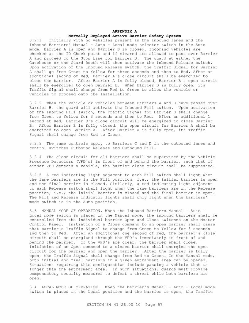
APPENDI X ANor mal l y Depl oyed Act i ve Bar r i er Saf et y Syst em
3. 2. 1 I ni t i al l y wi t h no vehi c l es pr esent i n t he i nbound l anes and t he I nbound Bar r i er s ' Manual - Aut o - Local mode sel ect or swi t ch i n t he Aut o mode, Bar r i er A i s open and Bar r i er B i s c l osed. I ncomi ng vehi c l es ar e checked at t he I D Check poi nt and i f c l ear ed ar e al l owed t o pass over Bar r i er A and pr oceed t o t he St op Li ne f or Bar r i er B. The guar d at ei t her t he Gat ehouse or t he Guar d Boot h wi l l t hen act i vat e t he I nbound Rel ease swi t ch. Upon act i vat i on of t he I nbound Rel ease swi t ch, t he Tr af f i c Si gnal f or Bar r i er A shal l go f r om Gr een t o Yel l ow f or t hr ee seconds and t hen t o Red. Af t er an addi t i onal second of Red, Bar r i er A' s c l ose c i r cui t shal l be ener gi zed t o c l ose t he bar r i er . Af t er Bar r i er A i s f ul l y c l osed, Bar r i er B' s open ci r cui t shal l be ener gi zed t o open Bar r i er B. When Bar r i er B i s f ul l y open, i t s Tr af f i c Si gnal shal l change f r om Red t o Gr een t o al l ow t he vehi c l e or vehi c l es t o pr oceed ont o t he I nst al l at i on.
3. 2. 2 When t he vehi c l e or vehi c l es bet ween Bar r i er s A and B have passed over Bar r i er B, t he guar d wi l l act i vat e t he I nbound Fi l l swi t ch. Upon act i vat i on of t he I nbound Fi l l swi t ch, t he Tr af f i c Si gnal f or Bar r i er B shal l change f r om Gr een t o Yel l ow f or 3 seconds and t hen t o Red. Af t er an addi t i onal 1 second at Red, Bar r i er B' s c l ose c i r cui t wi l l be ener gi zed t o c l ose Bar r i er B. Af t er Bar r i er B i s f ul l y c l osed, t he open ci r cui t f or Bar r i er A shal l be ener gi zed t o open Bar r i er A. Af t er Bar r i er A i s f ul l y open, i t s Tr af f i c Si gnal shal l change f r om Red t o Gr een.
3. 2. 3 The same cont r ol s appl y t o Bar r i er s C and D i n t he out bound l anes and cont r ol swi t ches Out bound Rel ease and Out bound Fi l l .
3. 2. 4 The cl ose c i r cui t f or al l bar r i er s shal l be super vi sed by t he Vehi c l e Pr esence Det ect or s ( VPD' s) i n f r ont of and behi nd t he bar r i er , such t hat i f ei t her VPD det ect s a vehi c l e, t he bar r i er c l ose c i r cui t shal l be suppr essed.
3. 2. 5 A r ed i ndi cat i ng l i ght adj acent t o each Fi l l swi t ch shal l l i ght when t he l ane bar r i er s ar e i n t he Fi l l posi t i on, i . e. , t he i ni t i al bar r i er i s open and t he f i nal bar r i er i s c l osed. Si mi l ar l y, a r ed i ndi cat i ng l i ght adj acent t o each Rel ease swi t ch shal l l i ght when t he l ane bar r i er s ar e i n t he Rel ease posi t i on, i . e. , t he i ni t i al bar r i er i s c l osed and t he f i nal bar r i er i s open. The Fi l l and Rel ease i ndi cat or l i ght s shal l onl y l i ght when t he bar r i er s ' mode swi t ch i s i n t he Aut o posi t i on.
3. 3 MANUAL MODE OF OPERATI ON. When t he I nbound Bar r i er s Manual - Aut o - Local mode swi t ch i s pl aced i n t he Manual mode, t he i nbound bar r i er s shal l be cont r ol l ed f r om t he i ndi v i dual bar r i er Open and Cl ose swi t ches on t he Mast er Cont r ol Panel . I ni t i at i on of a Cl ose command t o an open bar r i er shal l cause t hat bar r i er ' s Tr af f i c Si gnal t o change f r om Gr een t o Yel l ow f or 3 seconds and t hen t o Red. Af t er an addi t i onal one second of Red, t he bar r i er ' s c l ose c i r cui t shal l be ener gi zed t hr ough t he VPD' s i mmedi at el y i n f r ont of and behi nd t he bar r i er . I f t he VPD' s ar e c l ear , t he bar r i er shal l c l ose. I ni t i at i on of an Open commend t o a c l osed bar r i er shal l ener gi ze t he open ci r cui t f or t he bar r i er and open t he bar r i er . Af t er t he bar r i er i s f ul l y open, t he Tr af f i c Si gnal shal l change f r om Red t o Gr een. I n t he Manual mode, bot h i ni t i al and f i nal bar r i er s i n a gi ven ent r apment ar ea can be opened. Si t uat i ons r equi r i ng t hi s conf i gur at i on i ncl ude passi ng a vehi c l e t hat i s l onger t han t he ent r apment ar ea. I n such s i t uat i ons, guar ds must pr ovi de compensat or y secur i t y measur es t o def eat a t hr eat whi l e bot h bar r i er s ar e open.
3. 4 LOCAL MODE OF OPERATI ON. When t he bar r i er ' s Manual - Aut o - Local mode swi t ch i s pl aced i n t he Local posi t i on and t he bar r i er i s open, t he Tr af f i c
SECTI ON 34 41 26. 00 10 Page 57

APPENDI X ANor mal l y Depl oyed Act i ve Bar r i er Saf et y Syst em
Signal f or t hat bar r i er shal l change f r om Gr een t o Yel l ow f or 3 seconds and t hen t o Red. I f t he bar r i er i s c l osed when i t s Manual - Aut o - Local mode swi t ch i s pl aced i n t he Local posi t i on, t he Tr af f i c Si gnal wi l l al r eady be Red and shal l s t ay Red as l ong as t he sel ect or swi t ch i s i n t he Mai nt enance posi t i on. When t he bar r i er ' s Manual - Aut o - Local mode swi t ch i s r et ur ned t o t he Manual or Aut o posi t i ons, t he Tr af f i c s i gnal shal l s t ay Red i f t he bar r i er i s c l osed or shal l change t o Gr een i f t he Bar r i er i s open.
3. 5 OUTBOUND ENTRAPMENT AREA: A VPD l ocat ed i mmedi at el y i n f r ont of t he f i nal bar r i er ' s STOP l i ne shal l det ect a vehi c l e' s pr esence i n t he ent r apment ar ea. I f t he f i nal bar r i er i s c l osed, a s i gnal shal l be sent t o t he guar d i n t he Gat ehouse not i f y i ng hi m/ her of t he vehi c l e' s pr esence. The si gnal shal l cause a shor t audi bl e noi se t o al er t t he guar d and shal l t ur n on a Red i ndi cat i ng l i ght unt i l t he f i nal bar r i er i s open.
SECTI ON 34 41 26. 00 10 Page 58

APPENDI X APr esence Det ect i on Act i ve Bar r i er Saf et y Syst em
[ NOTE TO DESI GNER. I ncl ude a dr awi ng showi ng t he cont r ol swi t ches and cont r ol l ogi c f or t hi s scheme. Use Dr awi ngs E1. 03 and ei t her E1. 05 ( no queue pr eempt i on) or E1. 06 ( queue pr eempt i on) i n t he St andar d Desi gn or pr ovi de new dr awi ngs i f t he cont r ol swi t ches and cont r ol s on Dr awi ng E1. 03, E1. 05, or E1. 06 ar e modi f i ed. I f t he cont r ol s ar e modi f i ed f r om Dr awi ngs E1. 03, E1. 05, or E10. 6, t he f ol l owi ng cont r ol sequences must al so be modi f i ed. ]
1 PRESENCE DETECTI ON SAFETY SCHEME FEATURES. Pr ovi de t he f ol l owi ng f eat ur es f or t he Pr esence Det ect i on Saf et y Scheme:
1. 1 One Act i ve Vehi c l e Bar r i er at t he end of t he Response Zone i n each i nbound and each out bound l ane.
1. 2 Dual phenomenol ogy vehi c l e pr esence det ect or s ( VPDs) l ocat ed i n f r ont of t he St op Li ne ( det ect or s 1a and 1b) , bet ween t he St op Li ne and t he bar r i er ( det ect or s 2a and 2b) , and i mmedi at el y af t er t he bar r i er ( det ect or s 3a and 3b) . Pr esence det ect or s can be i nduct i on l oops, I R Br eak Beams, v i deo mot i on sensor s, or ot her sui t abl e t echnol ogi es capabl e of sensi ng vehi c l e pr esence.
1. 3 Passi ve bar r i er s on r ai sed i s l ands bet ween each i nbound and each out bound l ane. Passi ve bar r i er s and i s l ands shal l ext end f r om j ust ahead of t he r ange of VPDs 1a and 1b t o j ust beyond t he t r ai l i ng edge of t he r ange of VPDs 3a and 3b. See Dr awi ngs.
1. 4 Passi ve bar r i er on a r ai sed medi an i s l and bet ween t he i nner most i nbound and out bound l anes. Passi ve bar r i er and medi an i s l and shal l ext end f r om t he end of t he l ast Tur n- ar ound t o ei t her t he t r ai l i ng edge of r ange of t he i nbound VPDs 3a and 3b or t he l eadi ng edge of t he out bound VPDs 1a and 1b, whi chever i s f ur t her . See Dr awi ngs.
1. 5 A t hr ee l i ght Tr af f i c Si gnal at each i nbound and out bound l ane. The t hr ee l i ght s i n each Tr af f i c Si gnal shal l be Red- Yel l ow- Gr een t op t o bot t om. The Tr af f i c Si gnal shal l be l ocat ed 3. 5 f eet behi nd t he f r ont edge of t he St op Li ne as a dr i ver nor mal l y appr oaches t he bar r i er s.
1. 6 A 2 f oot wi de St op Li ne pl aced 24 f eet i n f r ont of t he act i ve vehi c l e bar r i er as a dr i ver nor mal l y appr oaches t he bar r i er .
1. 7 Act uat ed Tr af f i c Ar m 11. 5 f eet beyond t he f r ont edge of t he St op Li ne. Pr ovi de an Aut o- Test sel ect or swi t ch and Open and Cl ose swi t ches f or t he ATA i n t he Bar r i er Cont r ol Cabi net . I n t he Aut o mode of t he sel ect or swi t ch, t he ATA cont r ol shal l mi mi c t he adj acent act i ve vehi c l e bar r i er . I n t he Test mode of t he sel ect or swi t ch, t he ATA shal l be cont r ol l ed by t he Open and Cl ose swi t ches.
1. 8 Vehi c l e pr esence det ect i on syst ems t o det ect queues on any i nbound or out bound l anes i n f r ont of t he bar r i er ( s) . VPDs shal l be a mi ni mum of 117 f eet i n f r ont of t he f r ont edge of t he St op Li ne and shal l cover an ar ea t he wi dt h of t he l ane( s) by 50 f eet l ong. Mul t i pl e l oops may be used t o achi eve t he 50 f oot r equi r ed l engt h.
1. 9 One Mast er Cont r ol Panel , one Guar d Boot h Cont r ol panel f or each Guar d Boot h, one Over wat ch Posi t i on Cont r ol Panel , and a Local Cont r ol Panel f or each bar r i er al ong wi t h al l cont r ol swi t ches and i ndi cat i ng l i ght s as shown
SECTI ON 34 41 26. 00 10 Page 59

APPENDI X APr esence Det ect i on Act i ve Bar r i er Saf et y Syst em
on t he Dr awi ngs. The Mast er Cont r ol Panel wi l l nor mal l y be l ocat ed i n t he Gat ehouse f or use by t he ACP guar ds. Each Local Cont r ol Panel f or an i ndi v i dual bar r i er shal l be l ocat ed l ocal l y at or near i t s r espect i ve bar r i er .
1. 10 Act uat ed Tr af f i c Ar m f or each i nbound l ane i n t he I D Check Ar ea. ATAs shal l be i nst al l ed near t he Guar d Boot hs as shown on t he Dr awi ngs. An ATA Cont r ol Panel wi t h Open and Cl ose cont r ol swi t ches f or t he ATA shal l be pr ovi ded and mount ed on t he back wal l of t he Guar d Boot h bel ow t he back window.
2 BARRI ER CONTROL SWI TCHES.
2. 1 Per t he Dr awi ngs, t he Mast er Cont r ol Panel shal l have a Cont r ol Power On/ Of f swi t ch and each bar r i er shal l have a 3 posi t i on mode sel ect or swi t ch and Open and Cl ose swi t ches. Al so per t he Dr awi ngs, t he Mast er Cont r ol Panel and t he Guar d Boot h and Over wat ch Posi t i on Cont r ol Panel s shal l have EFO swi t ches. Each bar r i er shal l al so have a 2 posi t i on mode sel ect or swi t ch and Open and Cl ose swi t ches on a Local Cont r ol Panel l ocat ed at or near t he barrier.
2. 2 The modes on each bar r i er ' s mode sel ect or on t he Mast er Cont r ol Panel shal l be Local - EFO - Test . Each swi t ch shal l be oper abl e by a key uni que f or t hat swi t ch onl y, whi ch shal l be r emovabl e i n al l modes. The modes of each bar r i er ' s mode sel ect or swi t ch on t he Local Cont r ol Panel shal l be Of f - Local . Each swi t ch shal l be oper abl e by t he same key t hat oper at es t he mode sel ect or swi t ch f or t hat bar r i er on t he Mast er Cont r ol Panel . The key wi l l be r emovabl e i n t he " Of f " posi t i on onl y of t he Of f - Local mode sel ect or switch.
2. 3 Oper at i ng Modes.
2. 3. 1 EFO Oper at i on. Under nor mal oper at i ons, al l bar r i er s ' mode sel ect or swi t ches on t he Mast er Cont r ol Panel wi l l be i n t he EFO posi t i on wi t h t he key r emoved and accessi bl e onl y by t he l ead ACP guar d. Wi t h t he bar r i er ' s mode sel ect or swi t ch i n t he EFO posi t i on, EFO shal l be enabl ed f or t hat bar r i er , but t he Open and Cl ose swi t ches f or t hat bar r i er on t he Mast er Cont r ol Panel and t he Open and Cl ose swi t ches on t hat bar r i er ' s Local Cont r ol Panel shal l be di sabl ed.
2. 3. 2 Test Oper at i on. An i ndi v i dual bar r i er can be t est oper at ed by i nst al l i ng t he pr oper l ane mar ki ngs and passi ve bar r i er s ahead of t he act i ve bar r i er and t hen pl aci ng i t s mode sel ect or swi t ch i n t he Test posi t i on. Wi t h t he bar r i er ' s mode sel ect or swi t ch i n t he Test posi t i on, t hat bar r i er ' s Open and Cl ose swi t ches on t he Mast er Cont r ol Panel shal l be enabl ed, but t he Open and Cl ose swi t ches on t hat bar r i er ' s Local Cont r ol Panel shal l be di sabl ed and al l EFO swi t ches shal l be di sabl ed f or t hat bar r i er onl y.
2. 3. 3 Local Oper at i on. The Local mode can be used when mai nt enance per sonnel need t o per f or m mai nt enance on t he bar r i er . Mai nt enance per sonnel woul d obt ai n t he mode sel ect or swi t ch key f r om t he l ead ACP guar d, pl ace t he bar r i er ' s mode sel ect or swi t ch on t he Mast er Cont r ol Panel i n t he Local posi t i on, and t hen r emove t he key. Wi t h t he bar r i er ' s mode sel ect or swi t ch on t he Mast er Cont r ol Panel i n t he Local posi t i on, t hat bar r i er ' s Open and Cl ose swi t ches on t he Mast er Cont r ol Panel shal l be di sabl ed and al l EFO swi t ches shal l be di sabl ed f or t hat bar r i er onl y. The mai nt enance per son woul d t hen i nser t t he key i nt o t he Of f - Local mode sel ect or swi t ch on t he bar r i er ' s Local Cont r ol Panel and t ur n t he key t o t he " Local " posi t i on, whi ch shal l enabl e
SECTI ON 34 41 26. 00 10 Page 60

APPENDI X APr esence Det ect i on Act i ve Bar r i er Saf et y Syst em
the Open and Cl ose swi t ches on t he bar r i er ' s Local Cont r ol Panel . Mai nt enance per sonnel woul d al so have t o bl ock and mar k t he l ane ahead of t he bar r i er and al so l ock and t ag out cer t ai n equi pment at t he bar r i er per t he bar r i er manuf act ur er ' s r ecommendat i ons f or t he t ype of mai nt enance t o be performed.
3 TRAFFI C SI GNAL AND BARRI ER CONTROLS.
3. 1 EFO MODE OF OPERATI ON. I n t he EFO mode of oper at i on wi t h t he bar r i er open and no vehi c l es on VPD 1a or 1b, t he Tr af f i c Si gnal shal l be Red. I f a vehi c l e i s det ect ed by ei t her VPD 1a or 1b, t her e shal l be a one second del ay and t hen t he Tr af f i c Si gnal shal l change f r om Red t o Gr een t o al l ow t he vehi c l e t o pass over t he bar r i er . Once t he vehi c l e i s det ect ed by ei t her VPD 2a or 2b, t he Tr af f i c Si gnal shal l change f r om Gr een back t o Red. Thi s oper at i on i s s i mi l ar t o Lane Met er i ng on f r eeway ent r ances. I f a vehi c l e i s det ect ed by VPD 2a, 2b, 3a, or 3b at t he i nst ant a guar d act i vat es t he bar r i er Emer gency Fast Oper at e ( EFO) command, t he bar r i er " Cl ose" c i r cui t shal l be suppr essed unt i l VPD' s 2a, 2b, 3a, and 3b ar e al l c l ear . Al so, i f a guar d act i vat es t he Emer gency Fast Oper at e ( EFO) command and t he Tr af f i c Si gnal i s Gr een, t he Tr af f i c Si gnal shal l change f r om Gr een t o Red and t he bar r i er " Cl ose" c i r cui t shal l be suppr essed unt i l t he vehi c l e i s det ect ed by ei t her VPD 2a or 2b. I f t he vehi c l e i s det ect ed by VPD 2a or 2b, t he suppr essi on wi l l cont i nue unt i l VPD' s 2a, 2b, 3a, and 3b ar e al l c l ear as descr i bed above. I f nei t her of t hese condi t i ons exi st at t he t i me t hat a bar r i er Emer gency Fast Oper at e ( EFO) command i s act i vat ed, t he bar r i er " Cl ose" Ci r cui t shal l not be suppr essed and t he bar r i er shal l i mmedi at el y c l ose i n i t s emer gency f ast mode ( 2 seconds or l ess) . See t ypi cal cont r ol schemat i cs on t he Dr awi ngs.
3. 2 [ NOTE TO DESI GNER: Del et e par agr aphs 3. 2 and 3. 3 i f Queue Oper at i on i s not r equi r ed. ] QUEUE OPERATI ON. I f vehi c l es back up behi nd t he St op Li ne dur i ng per i ods of heavy t r af f i c such t hat t he queue VPD det ect s a vehi c l e cont i nuousl y f or 30 seconds, t he Tr af f i c Si gnal shal l go f r om Lane Met er i ng oper at i on t o Queue oper at i on. I n t he Queue oper at i on, t he Tr af f i c Si gnal shal l change t o Fl ashi ng Yel l ow and vehi c l es wi l l be al l owed t o pass over t he bar r i er wi t hout st oppi ng at t he St op Li ne. The Queue oper at i on shal l end i mmedi at el y when t he Queue VPD does not det ect a vehi c l e. When t he Queue oper at i on ends, t he Tr af f i c s i gnal shal l change f r om Fl ashi ng Yel l ow t o Sol i d Yel l ow and t hen t o Red and r esume Lane Met er i ng oper at i on. The di st ance bet ween t he Queue VPD and t he St op Li ne i s such t hat t he l ast vehi c l e l eavi ng t he Queue VPD wi l l see t he Tr af f i c Si gnal change t o Sol i d Yel l ow and Red i n t i me t o have t o st op at t he St op Li ne. Si nce t hi s oper at i on r el i es on t he vehi c l es i n t he queue t o st op a t hr eat vehi c l e, t he l ast vehi c l e i n t he queue must st op at t he St op Li ne.
3. 3 EFO DURI NG QUEUE OPERATI ON. I f an EFO command i s act i vat ed f r om any of t he Cont r ol Panel s dur i ng Queue oper at i on, t he Tr af f i c Si gnal shal l go f r om Fl ashi ng Yel l ow t o Sol i d Yel l ow f or 4 seconds and t hen t o Sol i d Red. Af t er an addi t i onal 1 second of Sol i d Red, t he bar r i er c l ose c i r cui t shal l be ener gi zed, pr ovi ded t hat t her e ar e no vehi c l es det ect ed on VPD' s 2a, 2b, 3a, or 3b. I f a vehi c l e i s det ect ed on any of t hese VPD' s, t he bar r i er c l ose c i r cui t wi l l be suppr essed unt i l al l VPD' s ar e c l ear .
3. 4 EFO RESET. Af t er an EFO act i vat i on, guar ds wi l l c l ose al l i nbound and out bound l anes. Guar ds wi l l t hen act i vat e t he EFO Reset swi t ch on t he Mast er Cont r ol Panel t o r eset EFO, pl ace each bar r i er ' s mode swi t ch t o t he Test posi t i on, open each bar r i er usi ng t he Open swi t ches on t he Mast er
SECTI ON 34 41 26. 00 10 Page 61

APPENDI X APr esence Det ect i on Act i ve Bar r i er Saf et y Syst em
Control Panel , and t hen pl ace each bar r i er ' s mode swi t ch t o t he EFO posi t i on. Guar ds coul d t hen r eopen t he ACP.
3. 5 TEST AND LOCAL MODES OF OPERATI ON. When a bar r i er ' s mode swi t ch i s pl aced i n ei t her t he Local or Test modes, t he t r af f i c s i gnal f or t hat bar r i er , i f not al r eady r ed, shal l go f r om Gr een t o Yel l ow f or 3 seconds and t hen t o Red. As not ed above, bef or e a bar r i er ' s mode swi t ch i s pl aced i n ei t her t he Local or Test posi t i ons, t he oper at or must ensur e t hat t he l ane t hat t he bar r i er i s i n i s pr oper l y bl ocked and mar ked.
3. 6 RETURN TO EFO MODE. When t he bar r i er ' s mode swi t ch i s pl aced i n t he EFO mode and t he bar r i er i s open, t he bar r i er ' s Tr af f i c Si gnal shal l r ever t back t o t he RED/ GREEN l ane met er i ng oper at i on. I f a bar r i er ' s mode swi t ch i s pl aced i n t he EFO mode and t he bar r i er i s c l osed, t he bar r i er ' s Tr af f i c Si gnal shal l s t ay Red and an al ar m shal l be gener at ed on t he ACP TROUBLE wi ndow on t he Gat ehouse Cont r ol Panel .
SECTI ON 34 41 26. 00 10 Page 62

APPENDI X ASi gns and Si gnal s Act i ve Bar r i er Saf et y Syst em
[ NOTE TO DESI GNER. I ncl ude a dr awi ng showi ng t he cont r ol swi t ches and cont r ol l ogi c f or t hi s saf et y scheme. Use Dr awi ngs E1. 03 and E1. 04 i n t he St andar d Desi gn or pr ovi de a new dr awi ng i f t he cont r ol swi t ches and cont r ol s on Dr awi ngs E1. 03 and E1. 04 ar e modi f i ed. I f t he cont r ol s ar e modi f i ed f r om Dr awi ngs E1. 03 and E1. 04, car e must be t aken t o ensur e compl i ance wi t h t he secur i t y and saf et y cr i t er i a i n t he Ar my St andar d Desi gn. The cont r ol sequences descr i bed bel ow wi l l al so need t o be modi f i ed. ]
1 SI GNS AND SI GNALS SAFETY SCHEME FEATURES. Pr ovi de t he f ol l owi ng f eat ur es f or t he Si gns and Si gnal s Saf et y Syst em:
1. 1 Act i ve Vehi c l e Bar r i er s i n al l i nbound and out bound l anes.
1. 2 A t hr ee l i ght Tr af f i c Si gnal over each i nbound and out bound act i ve bar r i er . The t hr ee l i ght s i n each Tr af f i c Si gnal shal l be Red- Yel l ow- Gr een t op t o bot t om. The Tr af f i c Si gnal shal l be l ocat ed up t o 10 f eet behi nd t he act i ve bar r i er s as a dr i ver nor mal l y appr oaches t he bar r i er s.
1. 3 A 2 f oot wi de st op l i ne pl aced 40 f eet i n f r ont of t he t r af f i c s i gnal as a dr i ver nor mal l y appr oaches t he bar r i er s.
1. 4 Doubl e sol i d whi t e l i nes bet ween i nbound l anes appr oachi ng t he bar r i er s t o pr ohi bi t l ane changes i n f r ont of t he bar r i er s.
1. 5 Doubl e sol i d yel l ow l i nes bet ween adj acent i nbound and out bound l anes.
1. 6 Vehi c l e Pr esence Det ect or s ( VPDs) l ocat ed i mmedi at el y bef or e and i mmedi at el y af t er each bar r i er . VPDs can be i nduct i on l oops, v i deo mot i on sensor s, or ot her sui t abl e t echnol ogi es capabl e of sensi ng vehi c l e pr esence.
1. 7 War ni ng Si gn and Beacon wi t h al t er nat i ng yel l ow f l ashi ng l i ght s l ocat ed 150 f eet i n f r ont of t he bar r i er s.
1. 8 One Mast er Cont r ol Panel , one Guar d Boot h Cont r ol panel f or each Guar d Boot h, one Over wat ch Posi t i on Cont r ol Panel , and a Local Cont r ol Panel at each bar r i er al ong wi t h al l cont r ol swi t ches and i ndi cat i ng l i ght s as shown on t he Dr awi ngs. The Mast er Cont r ol Panel wi l l nor mal l y be l ocat ed i n t he Gat ehouse f or use by t he ACP guar ds. Each Local Cont r ol Panel f or an i ndi v i dual bar r i er shal l be l ocat ed l ocal l y at i t s r espect i ve bar r i er power unit.
1. 9 Act uat ed Tr af f i c Ar m f or each i nbound l ane i n t he I D Check Ar ea. ATAs shal l be i nst al l ed near t he Guar d Boot hs as shown on t he Dr awi ngs. An ATA Cont r ol Panel wi t h Open and Cl ose cont r ol swi t ches f or t he ATA shal l be pr ovi ded and mount ed on t he back wal l of t he Guar d Boot h bel ow t he back window. 2 BARRI ER CONTROL SWI TCHES.
2. 1 Per t he Dr awi ngs, t he Mast er Cont r ol Panel shal l have one Cont r ol Power On/ Of f swi t ch and each bar r i er shal l have a 3 posi t i on mode sel ect or swi t ch and Open and Cl ose swi t ches. Al so per t he Dr awi ngs, t he Mast er Cont r ol Panel and t he Guar d Boot h and Over wat ch Posi t i on Cont r ol Panel s shal l have EFO swi t ches. Each bar r i er shal l al so have a 2 posi t i on mode sel ect or swi t ch and Open and Cl ose swi t ches on a Local Cont r ol Panel l ocat ed at or near t he
SECTI ON 34 41 26. 00 10 Page 63

APPENDI X ASi gns and Si gnal s Act i ve Bar r i er Saf et y Syst em
barrier.
2. 2 The modes on each bar r i er ' s mode sel ect or on t he Mast er Cont r ol Panel shal l be Local - EFO - Test . Each swi t ch shal l be oper abl e by a key uni que f or t hat swi t ch onl y, whi ch shal l be r emovabl e i n al l modes. The modes of each bar r i er ' s mode sel ect or swi t ch on t he Local Cont r ol Panel shal l be Of f - Local . Each swi t ch shal l be oper abl e by t he same key t hat oper at es t he mode sel ect or swi t ch f or t hat bar r i er on t he Mast er Cont r ol Panel . The key wi l l be r emovabl e i n t he " Of f " posi t i on onl y of t he Of f - Local mode sel ect or switch.
2. 3 Oper at i ng Modes.
2. 3. 1 EFO Oper at i on. Under nor mal oper at i ons, al l bar r i er s ' mode sel ect or swi t ches on t he Mast er Cont r ol Panel wi l l be i n t he EFO posi t i on wi t h t he key r emoved and accessi bl e onl y by t he l ead ACP guar d. Wi t h t he bar r i er ' s mode sel ect or swi t ch i n t he EFO posi t i on, EFO shal l be enabl ed f or t hat bar r i er , but t he Open and Cl ose swi t ches f or t hat bar r i er on t he Mast er Cont r ol Panel and t he Open and Cl ose swi t ches on t hat bar r i er ' s Local Cont r ol Panel shal l be di sabl ed.
2. 3. 2 Test Oper at i on. An i ndi v i dual bar r i er can be t est oper at ed by i nst al l i ng t he pr oper l ane mar ki ngs and passi ve bar r i er s ahead of t he act i ve bar r i er and t hen pl aci ng i t s mode sel ect or swi t ch i n t he Test posi t i on. Wi t h t he bar r i er ' s mode sel ect or swi t ch i n t he Test posi t i on, t hat bar r i er ' s Open and Cl ose swi t ches on t he Mast er Cont r ol Panel shal l be enabl ed, but t he Open and Cl ose swi t ches on t hat bar r i er ' s Local Cont r ol Panel shal l be di sabl ed and al l EFO swi t ches shal l be di sabl ed f or t hat bar r i er onl y.
2. 3. 3 Local Oper at i on. The Local mode can be used when mai nt enance per sonnel need t o per f or m mai nt enance on t he bar r i er . Mai nt enance per sonnel woul d obt ai n t he mode sel ect or swi t ch key f r om t he l ead ACP guar d, pl ace t he bar r i er ' s mode sel ect or swi t ch on t he Mast er Cont r ol Panel i n t he Local posi t i on, and t hen r emove t he key. Wi t h t he bar r i er ' s mode sel ect or swi t ch on t he Mast er Cont r ol Panel i n t he Local posi t i on, t hat bar r i er ' s Open and Cl ose swi t ches on t he Mast er Cont r ol Panel shal l be di sabl ed and al l EFO swi t ches shal l be di sabl ed f or t hat bar r i er onl y. The mai nt enance per son woul d t hen i nser t t he key i nt o t he Of f - Local mode sel ect or swi t ch on t he bar r i er ' s Local Cont r ol Panel and t ur n t he key t o t he " Local " posi t i on, whi ch shal l enabl e t he Open and Cl ose swi t ches on t he bar r i er ' s Local Cont r ol Panel . Mai nt enance per sonnel woul d al so have t o bl ock and mar k t he l ane ahead of t he bar r i er and al so l ock and t ag out cer t ai n equi pment at t he bar r i er per t he bar r i er manuf act ur er ' s r ecommendat i ons f or t he t ype of mai nt enance t o be performed.
3 TRAFFI C SI GNAL AND BARRI ER CONTROLS.
3. 1 EFO MODE OF OPERATI ON. I n t he EFO mode of oper at i on wi t h t he bar r i er open, t he Tr af f i c Si gnal shal l be Gr een. Upon act i vat i on of an EFO command at any of t he Cont r ol Panel s, bar r i er emer gency c l osur e shal l be del ayed 4 seconds. Dur i ng t hi s 4 seconds, t he Tr af f i c Si gnal shal l change f r om Gr een t o Yel l ow f or 3 seconds and t hen t o Red. Af t er an addi t i onal one second at Red, t he bar r i er ' s emer gency c l ose c i r cui t shal l be ener gi zed t o c l ose t he bar r i er i n i t s emer gency f ast mode ( 2 seconds or l ess) pr ovi ded t hat t he VPDs i mmedi at el y i n f r ont of and behi nd t he bar r i er ar e c l ear . I f ei t her VPD det ect s a vehi c l e, t he bar r i er shal l not c l ose.
SECTI ON 34 41 26. 00 10 Page 64

APPENDI X ASi gns and Si gnal s Act i ve Bar r i er Saf et y Syst em
3. 2 EFO RESET. Af t er an EFO act i vat i on, guar ds wi l l c l ose al l i nbound and out bound l anes. Guar ds wi l l t hen act i vat e t he EFO Reset swi t ch on t he Mast er Cont r ol Panel t o r eset EFO, pl ace each bar r i er ' s mode swi t ch t o t he Test posi t i on, open each bar r i er usi ng t he Open swi t ches on t he Mast er Cont r ol Panel , and t hen pl ace each bar r i er ' s mode swi t ch t o t he EFO posi t i on. Guar ds coul d t hen r eopen t he ACP.
3. 3 TEST AND LOCAL MODES OF OPERATI ON. When a bar r i er ' s mode swi t ch i s pl aced i n ei t her t he Local or Test modes, t he t r af f i c s i gnal f or t hat bar r i er shal l go f r om Gr een t o Yel l ow f or 3 seconds and t hen t o Red. As not ed above, bef or e a bar r i er ' s mode swi t ch i s pl aced i n ei t her t he Local or Test posi t i ons, t he oper at or must ensur e t hat t he l ane t hat t he bar r i er i s i n i s pr oper l y bl ocked and mar ked.
3. 4 RETURN TO EFO MODE. When t he bar r i er ' s mode swi t ch i s pl aced i n t he EFO mode and t he bar r i er i s open, t he bar r i er ' s Tr af f i c Si gnal shal l change f r om Red t o Gr een. I f a bar r i er ' s mode swi t ch i s pl aced i n t he EFO mode and t he bar r i er i s c l osed, t he bar r i er ' s Tr af f i c Si gnal shal l s t ay Red and an al ar m shal l be gener at ed on t he ACP TROUBLE wi ndow on t he Gat ehouse Cont r ol Panel .
SECTI ON 34 41 26. 00 10 Page 65
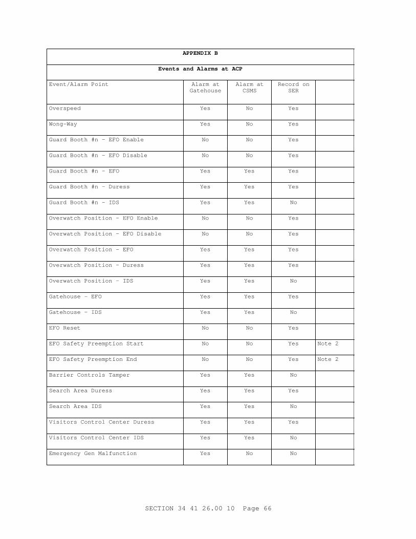
APPENDI X B
Event s and Al ar ms at ACP
Event / Al ar m Poi nt Al ar m atGatehouse
Al ar m atCSMS
Recor d onSER
Overspeed Yes No Yes
Wong-Way Yes No Yes
Guar d Boot h #n - EFO Enabl e No No Yes
Guar d Boot h #n - EFO Di sabl e No No Yes
Guar d Boot h #n - EFO Yes Yes Yes
Guar d Boot h #n - Dur ess Yes Yes Yes
Guar d Boot h #n - I DS Yes Yes No
Over wat ch Posi t i on - EFO Enabl e No No Yes
Over wat ch Posi t i on - EFO Di sabl e No No Yes
Over wat ch Posi t i on - EFO Yes Yes Yes
Over wat ch Posi t i on - Dur ess Yes Yes Yes
Over wat ch Posi t i on - I DS Yes Yes No
Gat ehouse - EFO Yes Yes Yes
Gat ehouse - I DS Yes Yes No
EFO Reset No No Yes
EFO Saf et y Pr eempt i on St ar t No No Yes Not e 2
EFO Saf et y Pr eempt i on End No No Yes Not e 2
Bar r i er Cont r ol s Tamper Yes Yes No
Sear ch Ar ea Dur ess Yes Yes Yes
Sear ch Ar ea I DS Yes Yes No
Vi si t or s Cont r ol Cent er Dur ess Yes Yes Yes
Vi si t or s Cont r ol Cent er I DS Yes Yes No
Emer gency Gen Mal f unct i on Yes No No
SECTI ON 34 41 26. 00 10 Page 66

APPENDI X B
Event s and Al ar ms at ACP
Event / Al ar m Poi nt Al ar m atGatehouse
Al ar m atCSMS
Recor d onSER
Emer gency Gen Swi t ch Over Yes No No
Emer gency Gen Swi t ch Back Yes No No
Emer gency Gen Low Fuel Yes No No
Bar r i er #n - EFO Mode No No Yes
Bar r i er #n - Test Mode No No Yes
Bar r i er #n - Local Mode No No Yes
Bar r i er #n - Cl ose Ckt Ener gi zed No No Yes
Bar r i er #n - Cl ose Command No No Yes
Bar r i er #n - Open Command No No Yes
Bar r i er #n - Cl osed No No Yes
Bar r i er #n - Open No No Yes
Bar r i er #n - Tr oubl e Yes No Yes
Que St ar t No No Yes
Que End No No Yes
Loop #1 Bar r i er n Mal f unct i on Yes No Yes
Loop #2 Bar r i er n Mal f unct i on Yes No Yes
Loop #3 Bar r i er n Mal f unct i on Yes No Yes
I R #6 Bar r i er n Mal f unct i on Yes No Yes
I R #7 Bar r i er n Mal f unct i on Yes No Yes
I R #8 Bar r i er n Mal f unct i on Yes No Yes
Not e 1: Cent r al Secur i t y Moni t or i ng St at i on - CSMS
Not e 2: Sequence of Event s Recor der - SER
Not e 3: Pr esence Det ect i on Saf et y Syst em onl y
Number of Event s 23+5* No of Gd Boot hs + 14* No of Bar r i er s
SECTI ON 34 41 26. 00 10 Page 67

Number of Al ar ms @ GH 11+3* No of Gd Boot hs+6* No of Bar r i er s
Number of Al ar ms @ CSMS 12+3* No of Gd Boot hs+6* No of Bar r i er s
Number of GB 2 8
Number of Bar r i er s 4 5
Number of Al ar ms @ GH 41 65
Number of Al ar ms @CSMS 42 66
Number of Event s 89 133
- - End of Sect i on - -
SECTI ON 34 41 26. 00 10 Page 68