(563 kb) - pier
TRANSCRIPT
Progress In Electromagnetics Research, Vol. 128, 1–17, 2012
COMPREHENSIVE ANALYSIS OF LENZ EFFECT ONTHE ARTIFICIAL HEART VALVES DURING MAG-NETIC RESONANCE IMAGING
L. Golestanirad1, *, E. Dlala2, G. Wright1, J. R. Mosig3, andS. J. Graham1
1Department of Medical Biophysics, University of Toronto, Toronto,Canada2ANSYS, Inc. Ann Arbor, Michigan, US3Laboratory of Electromagnetics and Acoustics, Ecole PolytechniqueFederale de Lausanne (EPFL), Lausanne 1015, Switzerland
Abstract—This work presents results of a comprehensive analysis ofthe Lenz effect due to motion of artificial heart valves during magneticresonance imaging. The interaction of rotating metallic heart valveswith magnetic fields is studied by performing a time-domain analysisof the corresponding electromagnetic problem. We applied the finiteelement method (FEM) to solve the T − Ω formulation of Maxwellequations in two cases: first, for metallic disks located in the highintensity homogenous field of the magnet iso-center, and second, diskslocated in the non-uniform fringe field of the bore entrance. We showedthat for valves with full solid disks (such as Starr-Edwards 6500)located in the magnet iso-center, the magnitude of adverse forces canbe comparable to the forces applied by the beating heart. However,for rings which consist of multiply connected conductive regions, skineffect and proximity effect counteract, which leads to a diminishedmagnetic force. Results of this study show that mechanical heartvalves with strengthening rings may be considered safe even underultra-high imaging conditions with field intensities as high as 10 T.However, heart valves with full conducting disks should be consideredas a contraindication to MR imaging.
Received 15 March 2012, Accepted 18 April 2012, Scheduled 12 May 2012* Corresponding author: Laleh Golestanirad ([email protected]).
2 Golestanirad et al.
1. INTRODUCTION
Cardiovascular magnetic resonance (CMR) is a gold standard imagingmodality for the evaluation of patients with cardiovascular conditions.The technique is increasingly used for estimation of myocardialstructure, wall motion, perfusion and viability. In addition, CMRhas inherent safety advantages, particularly, its noninvasive natureand the absence of exposure to ionizing radiation [1, 2]. As a result,a significant increase in the number of magnetic resonance imaging(MRI) scans performed annually has been observed including MRI ofpatients with cardiovascular implants. Although millions of patientshave implanted cardiac devices, MRI was not for many years allowedfor these patients because of the potential interference of MRI machineswith their devices [3]. It was estimated that at least 200,000 patientswith cardiac devices had been denied an MRI scan in 2004 alone [4].
Prosthetic heart valves and annuloplasty rings are commonlycomposites of different metallic materials such as chromium, cobalt,stainless steel and pyrolytic carbon [5, 6] which when tested, mostlyhave exhibited measurable but only minor magnetic field interactionsdue to translational and torsion forces. The magnetic attractive forceson heart valves and annuloplasty rings have been found to be muchless than the 7.2-N force exerted by a beating heart [7]. Consequently,the American College of Cardiology Foundation/American HeartAssociation have considered heart valves and coronary stents to beMR compatible, since they are non-ferromagnetic.
Nevertheless, some concerns have been raised in the past after atheoretical assessment of moving valves with tilting disks or leafletswhen considering the Lenz effect. According to the theory, a resistiveforce may develop in the valve due to its motion in the magnetic fieldthat inhibits the valve from either opening or closing. Although theadverse effects of Lenz forces have not been clinically reported, thetheoretical assessment indicated that these forces could reach valuesup to 100 times greater than those associated to ferromagnetism [8, 9].
This concern seems more rational considering the fast pace towardultra-high field MR systems, which already use static fields as high as11.7T in research on human subjects and 7 T for clinical applications.Despite the need for having a reliable estimation of the significance ofLenz forces on heart valves, theoretical efforts to formulate the problemremain limited. To the authors knowledge, the only quantitativeworks on this problems are those by Condon and Hadley [8] andRobertson et al. [9]. These works raised an alarm and drew theattention of researchers to a potentially significant source of interactionbetween passive metallic implants and static magnetic fields which
Progress In Electromagnetics Research, Vol. 128, 2012 3
was overlooked in the conventional approach. However, the resultswere hindered by an oversimplified formulation of the electromagneticproblem. For example, Condon and Hadley [8] used a simple modelbased on first order eddy currents to estimate maximum forces appliedon heart valves with metal strengthening ring. The results predictedconcerning high forces even at relatively low field values (1.5 T),particularly for heart valves in the mitral position. Normal openingand closing pressure differentials are much less in the mitral positionthan for valves in the aortic position. The model nevertheless, wasbased on the first order estimation of eddy currents, which did notaccount for the skin effect: a phenomenon which will be shown tosignificantly reduce the overall currents and torques.
In this contribution, we describe a comprehensive analysis of therotational motion of conducting disks in both uniform and non-uniformmagnetic field regions of a typical MR scanner. We performed atime-domain analysis of the corresponding electromagnetic problemby applying the finite element method (FEM) to solve the Maxwellequations governing the motion in the presence of magnetic fields.In the case of a uniform magnetic field, in addition to the FEManalysis, analytical formulation has been derived based on the firstorder estimation of eddy currents. We demonstrated that in the caseof a full solid disk, the proposed simplified formulation agrees wellwith the prediction of the FEM analysis. In contrast, for moving ringsconsisting of multiple connected conductive regions, the superpositionof skin effect and proximity effect leads to significantly less appliedmagnetic force.
We also analyzed the movement of heart valves in highly non-uniform magnetic fields encountered in the fringe fields at bore entranceof an MRI magnet. This situation might be encountered when thepatient undergoes the imaging of the lower limb or knee, and thus isplaced in the magnet feet first. The heart valve may then be outsidethe highly homogeneous volume of the field and will move throughregions of rapidly changing flux density during the cardiac cycle. Thepossibility of adverse interactions in such cases was mentioned but notinvestigated in previous works.
The outline of this paper is as follows: Section 2 describesthe modeling and design of a typical MR magnet using FEMsimulations. Section 3 then analyzes the motion of the heart valve inthe homogenous field of the magnet iso-center and computes motion-induced forces. It shows that the predictions of the simplified analyticalsolutions are valid for full solid disks but cannot be extended to ringsand strengthening wires, which require a more rigorous method suchas the FEM. Finally, in Section 4, the motion of heart valves located
4 Golestanirad et al.
in the fringe field of a typical MRI scanner is analyzed to investigatethe effect of field inhomogeneity on the motion of heart valves.
2. MAGNET DESIGN AND MODELING
MRI magnets require the field uniformity better than 10 ppm (part permillion) within a spherical imaging volume of diameter 40 to 50 cm andare classified into two classes: shielded and unshielded magnets. In theformer case, the stray field may reach more than 100 gauss(G) and itneeds a special room for the magnet to protect the electronic equipmentfrom adverse effects. Next generation magnets came with the conceptof active shielding where the stray field is less than 4 G (in regionsat least 4 m away from the iso-center) either by using ferromagneticmaterials [11] or using coaxial coils carrying current in the oppositedirection [12]. Different methods are used to design magnets of highlyhomogeneous field, based on stochastic optimization [20], matrix subsetselection [21], inverse approach [22], hybrid numerical methods [23] andmethods for permanent magnet design [24].
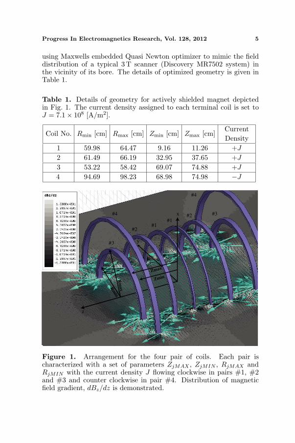
In this work, we started with the design parameters proposedby Sinha et al. [13] who used blocks of circular loops and optimizedthe block size to produce desired field uniformity on the axis. Fourpairs of coils were used (see Fig. 1) with the direction of current flowcounter clockwise in all the three smaller pairs. The current directionin the outermost coil pair was clockwise to model the effect of activeshielding. The magnet was symmetric about z = 0 plane and each pairof rectangular coil block was determined by four parameters: ZjMAX ,ZjMIN , RjMAX and RjMIN where j refers to the block number. Theseparameters were then optimized to achieve the desired field profile.
We used the Maxwell 3D [14] magneto-static solver which appliesFEM to solve the following two equations:
∇× ~H = ~J (1)
∇. ~B = 0 (2)
The Ansoft FEM solver was set to follow an adaptive iterative processwhereby an initial mesh was seeded according to the geometrical detailsof the structure, with approximately 72000 tetrahedral elements. Weset the adaptive solver to refine the mesh for 30% at each iterationand to continue refinement until the difference between two iterativesolutions was < 1%. The final number of tetrahedral elements wasapproximately 122000 cells. The four-coil magnet system was enclosedin a cubic box of 9 m length with the Neumann boundary conditionset on its outer faces. Block parameters and current values wereinitially chosen according to suggestions from [13] and were optimized
Progress In Electromagnetics Research, Vol. 128, 2012 5
using Maxwells embedded Quasi Newton optimizer to mimic the fielddistribution of a typical 3 T scanner (Discovery MR7502 system) inthe vicinity of its bore. The details of optimized geometry is given inTable 1.
Table 1. Details of geometry for actively shielded magnet depictedin Fig. 1. The current density assigned to each terminal coil is set toJ = 7.1× 10⁸ [A/m2].
Coil No. Rmin [cm] Rmax [cm] Zmin [cm] Zmax [cm]CurrentDensity
1 59.98 64.47 9.16 11.26 +J
2 61.49 66.19 32.95 37.65 +J
3 53.22 58.42 69.07 74.88 +J
4 94.69 98.23 68.98 74.98 −J
#1#1
#2
#2
#3
#3#4
#4
z
y
x
Zmin
Zmax
Rm
inR
max
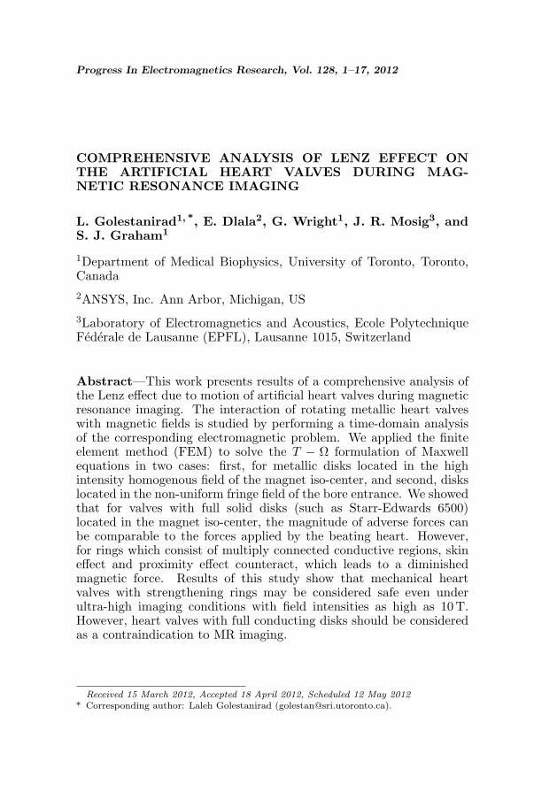
Figure 1. Arrangement for the four pair of coils. Each pair ischaracterized with a set of parameters ZjMAX , ZjMIN , RjMAX andRjMIN with the current density J flowing clockwise in pairs #1, #2and #3 and counter clockwise in pair #4. Distribution of magneticfield gradient, dBz/dz is demonstrated.
6 Golestanirad et al.
0 1 2 3 4 5 60
0.5
1
1.5
Distance from Iso Center[m]
Manit
ude o
f B
z [
T]
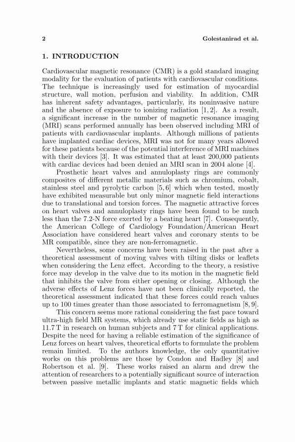
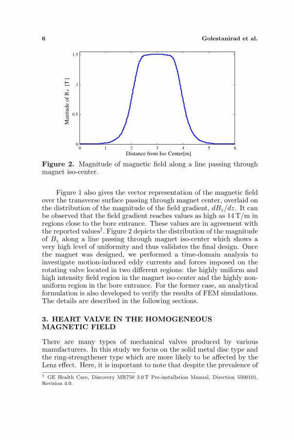
Figure 2. Magnitude of magnetic field along a line passing throughmagnet iso-center.
Figure 1 also gives the vector representation of the magnetic fieldover the transverse surface passing through magnet center, overlaid onthe distribution of the magnitude of the field gradient, dBz/dz. It canbe observed that the field gradient reaches values as high as 14 T/m inregions close to the bore entrance. These values are in agreement withthe reported values†. Figure 2 depicts the distribution of the magnitudeof Bz along a line passing through magnet iso-center which shows avery high level of uniformity and thus validates the final design. Oncethe magnet was designed, we performed a time-domain analysis toinvestigate motion-induced eddy currents and forces imposed on therotating valve located in two different regions: the highly uniform andhigh intensity field region in the magnet iso-center and the highly non-uniform region in the bore entrance. For the former case, an analyticalformulation is also developed to verify the results of FEM simulations.The details are described in the following sections.
3. HEART VALVE IN THE HOMOGENEOUSMAGNETIC FIELD
There are many types of mechanical valves produced by variousmanufacturers. In this study we focus on the solid metal disc type andthe ring-strengthener type which are more likely to be affected by theLenz effect. Here, it is important to note that despite the prevalence of† GE Health Care, Discovery MR750 3.0T Pre-installation Manual, Direction 5500101,Revision 4.0.

Progress In Electromagnetics Research, Vol. 128, 2012 7
non-metallic materials used to construct modern bi and single leafletmechanical valves, some older single leaflet valves used titanium andStellite. We also need to consider that older patients are more likely topossess older valves with metal components and, because of age, whichweakens the heart muscle, they are likely to be the most at risk.
3.1. First Order Estimation of Motion-Induced EddyCurrents: Analytical Solution
We adopted a unified approach to both solid disks and ring-strengthening valves by analyzing the hollow disk of Figure 3. By doingso, the ring-strengthening valve is the special case when a approachesb (a → b).
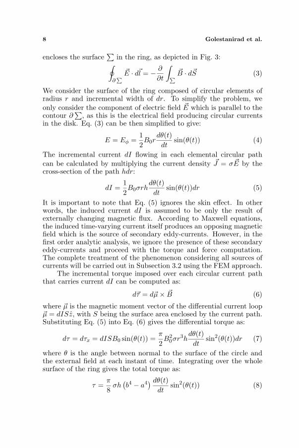
Suppose that a thin conducting ring with inner radius of a, outerradius of b and thickness of h is located in a uniform magnetic fieldB0, that without lack of generality, is assumed to lie in yz plane andmake the angle θ with the normal to the ring surface. If we assumethat the ring is rotating around the x axis such that θ is a function oftime θ(t), then the magnetic flux φ passing through the surface of thering also varies with time and according to Faradays law of induction,an electromotive force is induced along any closed contour ∂
∑which
a br
dr
z
B 0
h
di
x
y
Figure 3. Geometry of a rotating ring with inner radius of a, outerradius of b and thickness of h in a uniform magnetic field. The angle θbetween the magnetic field vector and the normal to the ring surfaceis a function of time as θ = θ(t).
8 Golestanirad et al.
encloses the surface∑
in the ring, as depicted in Fig. 3:∮
∂∑ ~E · d~l = − ∂
∂t
∫∑ ~B · d~S (3)
We consider the surface of the ring composed of circular elements ofradius r and incremental width of dr. To simplify the problem, weonly consider the component of electric field ~E which is parallel to thecontour ∂
∑, as this is the electrical field producing circular currents
in the disk. Eq. (3) can be then simplified to give:
E = Eφ =12B0r
dθ(t)dt
sin(θ(t)) (4)
The incremental current dI flowing in each elemental circular pathcan be calculated by multiplying the current density ~J = σ ~E by thecross-section of the path hdr:
dI =12B0σrh
dθ(t)dt
sin(θ(t))dr (5)
It is important to note that Eq. (5) ignores the skin effect. In otherwords, the induced current dI is assumed to be only the result ofexternally changing magnetic flux. According to Maxwell equations,the induced time-varying current itself produces an opposing magneticfield which is the source of secondary eddy-currents. However, in thefirst order analytic analysis, we ignore the presence of these secondaryeddy-currents and proceed with the torque and force computation.The complete treatment of the phenomenon considering all sources ofcurrents will be carried out in Subsection 3.2 using the FEM approach.
The incremental torque imposed over each circular current paththat carries current dI can be computed as:
d~τ = d~µ× ~B (6)
where ~µ is the magnetic moment vector of the differential current loop~µ = dISz, with S being the surface area enclosed by the current path.Substituting Eq. (5) into Eq. (6) gives the differential torque as:
dτ = dτx = dISB0 sin(θ(t)) =π
2B2
0σr3hdθ(t)dt
sin2(θ(t))dr (7)
where θ is the angle between normal to the surface of the circle andthe external field at each instant of time. Integrating over the wholesurface of the ring gives the total torque as:
τ =π
8σh
(b4 − a4
) dθ(t)dt
sin2(θ(t)) (8)
Progress In Electromagnetics Research, Vol. 128, 2012 9
The torque computed in (8) is the result of the superposition ofincremental Lorentzs forces applied to each elemental volume of thedisk. However, for a ring rotating around one hinged end, we canintroduce equivalent force acting on an effective lever arm of lengthequivalent to the rings diameter 2b:
F = T/2b (9)
3.2. Time-domain FEM Analysis of 3D Eddy Currents
To obtain a full description of the phenomenon and account for fieldinhomogeneities as well as higher order eddy currents, we need toaddress Maxwells equations directly in their quasi-static form. Inorder to do this, the designed magnet geometry described in Section 2design was imported into Maxwell 3D transient solver which appliesthe FEM to solve the T −Ω formulation of Maxwell’s equations whichis a well-developed technique adopted for modeling three-dimensionaleddy-current problems [18, 19]. The method is based on introducing amagnetic scalar potential Ω in the whole domain and a current vectorpotential ~T in the conducting region. More generally, the magneticfield H can be further split into four components [19]:
~H = ~Hs + ~T +∇Ω +∑
~Tk (10)
where ~Hs is the source field due to known total currents or knowncurrent densities in either solid conductors or stranded conductors, ~Tk
is the source field due to unknown currents in a voltage-driven strandedwinding k or solid conductor loop k. Applying Ampere’s law, Faraday’slaw, and Gauss’ law for the solenoidality of the flux density yields thedifferential equations in conducting region as:
∇×(
1σ∇× ~T
)+
d
dt
(µ~T + µ∇Ω +
∑µ~Tk
)= − d
dt(µHs) (11)
∇.(µ~T + µ∇Ω +
∑µ~Tk
)= −∇ · (µHs) (12)
where µ is the permeability. In non-conducting regions, the fieldequation reduces to:
∇.(µ∇Ω +
∑µ~Tk
)= −∇. (µHs) (13)
The problem region is then discretized into tetrahedral elements andthe standard FEM approach can be applied to solve the equations.
Maxwell 3D allows for both translational and rotational motionand automatically calculates motion-induced eddy currents. Thedetails of FEM implementation scheme can be found in [15].
10 Golestanirad et al.
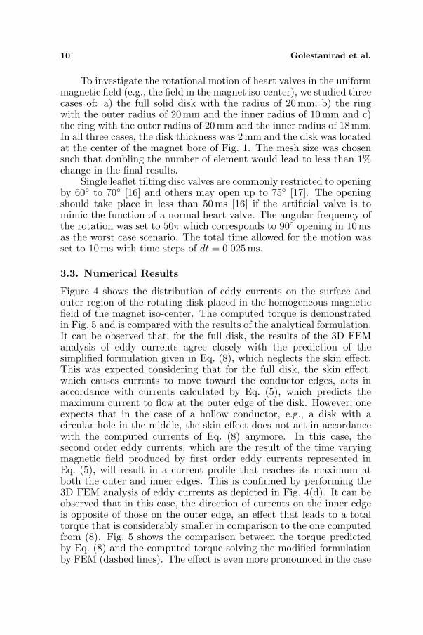
To investigate the rotational motion of heart valves in the uniformmagnetic field (e.g., the field in the magnet iso-center), we studied threecases of: a) the full solid disk with the radius of 20 mm, b) the ringwith the outer radius of 20mm and the inner radius of 10mm and c)the ring with the outer radius of 20 mm and the inner radius of 18 mm.In all three cases, the disk thickness was 2 mm and the disk was locatedat the center of the magnet bore of Fig. 1. The mesh size was chosensuch that doubling the number of element would lead to less than 1%change in the final results.
Single leaflet tilting disc valves are commonly restricted to openingby 60 to 70 [16] and others may open up to 75 [17]. The openingshould take place in less than 50 ms [16] if the artificial valve is tomimic the function of a normal heart valve. The angular frequency ofthe rotation was set to 50π which corresponds to 90 opening in 10msas the worst case scenario. The total time allowed for the motion wasset to 10ms with time steps of dt = 0.025ms.
3.3. Numerical Results
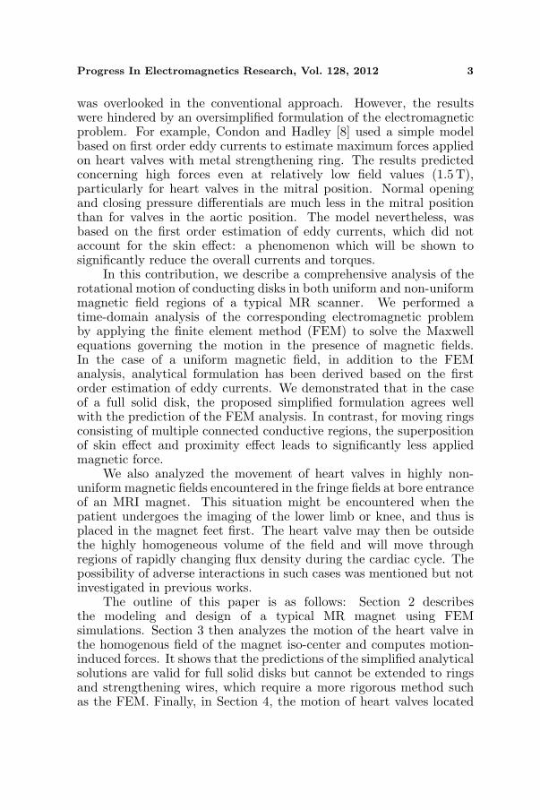
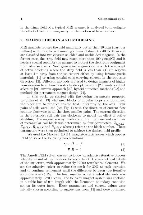
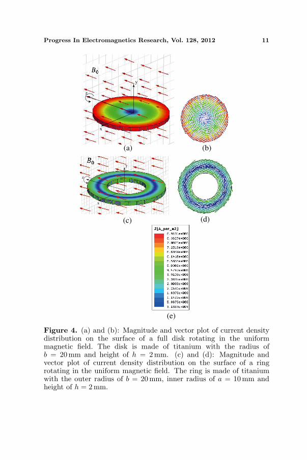
Figure 4 shows the distribution of eddy currents on the surface andouter region of the rotating disk placed in the homogeneous magneticfield of the magnet iso-center. The computed torque is demonstratedin Fig. 5 and is compared with the results of the analytical formulation.It can be observed that, for the full disk, the results of the 3D FEManalysis of eddy currents agree closely with the prediction of thesimplified formulation given in Eq. (8), which neglects the skin effect.This was expected considering that for the full disk, the skin effect,which causes currents to move toward the conductor edges, acts inaccordance with currents calculated by Eq. (5), which predicts themaximum current to flow at the outer edge of the disk. However, oneexpects that in the case of a hollow conductor, e.g., a disk with acircular hole in the middle, the skin effect does not act in accordancewith the computed currents of Eq. (8) anymore. In this case, thesecond order eddy currents, which are the result of the time varyingmagnetic field produced by first order eddy currents represented inEq. (5), will result in a current profile that reaches its maximum atboth the outer and inner edges. This is confirmed by performing the3D FEM analysis of eddy currents as depicted in Fig. 4(d). It can beobserved that in this case, the direction of currents on the inner edgeis opposite of those on the outer edge, an effect that leads to a totaltorque that is considerably smaller in comparison to the one computedfrom (8). Fig. 5 shows the comparison between the torque predictedby Eq. (8) and the computed torque solving the modified formulationby FEM (dashed lines). The effect is even more pronounced in the case
Progress In Electromagnetics Research, Vol. 128, 2012 11
x
y
z
x
y
z
(a) (b)
(c) (d)
(e)
Figure 4. (a) and (b): Magnitude and vector plot of current densitydistribution on the surface of a full disk rotating in the uniformmagnetic field. The disk is made of titanium with the radius ofb = 20mm and height of h = 2 mm. (c) and (d): Magnitude andvector plot of current density distribution on the surface of a ringrotating in the uniform magnetic field. The ring is made of titaniumwith the outer radius of b = 20 mm, inner radius of a = 10mm andheight of h = 2 mm.
12 Golestanirad et al.
0 2 4 6 8 10350
300
250
200
150
100
50
0
50
Time [ms]
Torq
ue
[,m
Nm
]
Solid Disk (a=0)
B=3T, =50
Ring (a=10mm)
Ring (a=18mm)
ω π
_
_
_
_
_
_
_
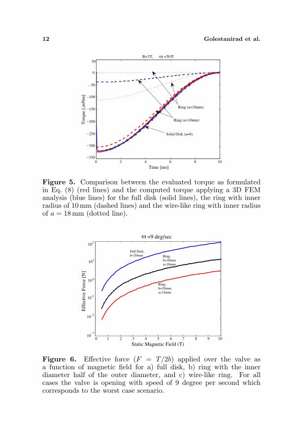
Figure 5. Comparison between the evaluated torque as formulatedin Eq. (8) (red lines) and the computed torque applying a 3D FEManalysis (blue lines) for the full disk (solid lines), the ring with innerradius of 10 mm (dashed lines) and the wire-like ring with inner radiusof a = 18 mm (dotted line).
0 1 2 3 4 5 6 7 8 9 1010
3
10 2
10 1
10 0
101
102
Static Magnetic Field (T)
Eff
ecti
ve
Forc
e [N
]
=9 deg/sec
Full Disk, b=20mm
Ring,b=20mma=18mm
Ring,b=20mma=10mm
_
_
_
ω
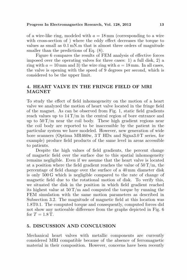
Figure 6. Effective force (F = T/2b) applied over the valve asa function of magnetic field for a) full disk, b) ring with the innerdiameter half of the outer diameter, and c) wire-like ring. For allcases the valve is opening with speed of 9 degree per second whichcorresponds to the worst case scenario.
Progress In Electromagnetics Research, Vol. 128, 2012 13
of a wire-like ring, modeled with a = 18mm (corresponding to a wirewith cross-section of ) where the eddy effect decreases the torque tovalues as small as 0.1 mN.m that is almost three orders of magnitudesmaller than the predictions of Eq. (8).
Figure 6 compares the results of FEM analysis of effective forcesimposed over the operating valves for three cases: 1) a full disk, 2) aring with a = 10mm and 3) the wire ring with a = 18 mm. In all cases,the valve is opening with the speed of 9 degrees per second, which isconsidered to be the upper limit.
4. HEART VALVE IN THE FRINGE FIELD OF MRIMAGNET
To study the effect of field inhomogeneity on the motion of a heartvalve we analyzed the motion of heart valve located in the fringe fieldof the magnet. As can be observed from Fig. 1, static field gradientsreach values up to 14 T/m in the central region of bore entrance andup to 50T/m near the coil body. These high gradient regions nearthe coil body are reported to be inaccessible by the patient in theparticular system we have modeled. However, new generation of widebore scanners (Optima MR460w, 3 T HDx and Signa3.0 T series, forexample) produce field products of the same level in areas accessibleto patients.
Despite the high values of field gradients, the percent changeof magnetic field over the surface due to this spatial inhomogeneityremains negligible. Even if we assume that the heart valve is locatedat a position where the field gradient reaches the value of 50 T/m, thepercentage of field change over the surface of a 40 mm diameter diskis only 500 G which is negligible compared to the rate of change ofmagnetic field due to the rotational motion of disk. To verify this,we situated the disk in the position in which field gradient reachedits highest value at 50 T/m and computed the torque by running theFEM simulation with the same motion parameters as described inSubsection 3.2. The magnitude of magnetic field at this location was1.8T0.1. The computed torque and consequently, computed forces didnot show any noticeable difference from the graphs depicted in Fig. 6for T = 1.8T.
5. DISCUSSION AND CONCLUSION
Mechanical heart valves with metallic components are currentlyconsidered MRI compatible because of the absence of ferromagneticmaterial in their composition. However, concerns have been recently
14 Golestanirad et al.
raised hypothesizing the potential adverse effects of Lenz forces inducedby valve motion. The concern seems even more rational consideringthe fast advancements toward ultra-high field imaging systems whichalready use field intensities up to 11.7T. Consequently, a reliableestimation of magnitude of these forces is needed to establish safe andyet not unnecessarily restrictive safety guidelines.
This work presented a rigorous investigation of the Lenz effecton the artificial heart valves during magnetic resonance imaging. InSubsection 3.1, we derived analytical solutions based on the first orderestimation of eddy currents. The predictions of the analytical solutionwere compared with the results of the full-wave analysis for both soliddisk and the doubly connected conducting ring. We demonstrated thatin the latter case, the formation of higher order eddy currents, whichlead to the well-known skin effect phenomenon, reduces the total torqueand hence, the effective force applied over the ring surface. However,in all cases, the magnitude of the adverse force increases in proportionto the square of magnetic field. It can be observed from Figure 6 thatfor the solid disk, the magnitude of Lenz force reaches values as highas 100 N for the magnetic field of 10 T. However, for the wire-like ring,this value remains below 2 N in the whole range of magnetic fields.
We also investigated the effect of high spatial inhomogeneity ofmagnetic fields at the bore entrance of typical MR scanners. Therehave been concerns about the situations where the patient undergoesthe MRI of lower limb and so enters the scanner feet first. In thiscase, the heart valve is positioned in the fringe field of the magnet,which is known to be highly inhomogeneous. The spatial distributionof magnetic field is investigated by modeling the full actively shieldedmagnet. The result of our modeling showed that the percentage ofchange of magnetic field over the valve surface is negligible comparedto the rate of change of magnetic flux due to the rotational motion ofthe valve. In other words, the worst case estimation of Lenz effect dueto operation of heart valves corresponds to the motion of heart valvein the homogeneous high intensity field of magnet iso-center.
In this work, we only investigated the effect of static magnetic.There are other sources of electromagnetic interaction between theMR scanner and metallic objects, such as switching gradients and theRF excitation pulse. However, these sources have a negligible effecton the rotation of heart valves. For example, the amplitude of a 1 msRF pulse required for a 90 flip angle is only 5.9µT and the typicalmagnitude of spatial gradients is in the order of few millitesla (mT).Therefore, these fields do not produce a significant Lorentz force.
In summary, the result of this study shows that mechanical heartvalves with strengthening rings may be considered safe even under
Progress In Electromagnetics Research, Vol. 128, 2012 15
ultra-high imaging conditions with field intensities as high as 10 T.This conclusion is based on the fact that the magnitude of Lenz forcesdue to the valve rotational motion in this case is less than typicalforces of a beating heart which is 7.2 N. However, heart valves such asStarr- Edwards 6500 which have solid metallic disk are subject to highadverse forces during MRI even at typical clinical field intensities. Forexample, the resistive force applied over the surface of a valve withtitanium metallic disk at 4 T is approximately 14 N. Considering thesurface of the valve, which is 12.6 cm2, this force is applying a pressureof 83 mmHg over the valves disk. If the valve is located in mitralposition, it should open and close under a pressure difference of onlya fewmmHg (less than 4 mmHg) between the relaxing left ventricleand the left atrium. High resistive pressures as the one computedhere, could severely hinder the normal operation of the heart valveand thus, heart valves with full conducting disks should be consideredas contraindication to MR imaging.
ACKNOWLEDGMENT
This work was partially supported by a research grant from SwissNational Science Foundation (grant PBELP2-135868).
REFERENCES
1. Pennell, D., U. Sechtem, C. Higgins, W. Manning, G. Pohost,F. Rademakers, A. van Rossum, L. Shaw, and E. Yucel,“Clinical indications for cardiovascular magnetic resonance(CMR): Consensus panel report,” J. Cardiovasc Magn. Reson.,Vol. 6, No. 4, 727–765, 2004.
2. Mavrogeni, S., F. Rademakers, and D. Cokkinos, “Clinicalapplication of cardiovascular magnetic resonance,” Hellenic J.Cardiol., Vol. 45, 401–405, 2004.
3. Roguin, A. and D. Goldsher, “Magnetic resonance imaging andimplantable cardiac electronic devices: It’s not what we can do,it’s what we should do,” Isr. Med. Assoc. J., Vol. 12, No. 7, 436–438, 2008.
4. Kalin, R. and M. Stanton, “Current clinical issues for MRIscanning of pacemaker and defibrillator patients,” Pacing Clin.Electrophysiol., Vol. 28, 326–328, 2005.
5. Shellock, F. and S. Morisoli, “Ex vivo evaluation of ferro-magnetism, heating, and artifacts produced by heart valve

16 Golestanirad et al.
prostheses exposed to a 1.5 T MR system,” J. Magn. Reson.Imaging , Vol. 4, 756–758, 1994.
6. Edwards, M., K. Taylor, and F. Shellock, “Prosthetic heart valves:Evaluation of magnetic field interactions, heating and artifacts at1.5T,” J. Magn. Reson. Imaging , Vol. 12, 363–369, 2000.
7. Soulen, R., T. Budinger, and C. Higgins, “Magnetic resonanceimaging of prosthetic heart valves,” Radiology , Vol. 154, 705–707,1985.
8. Condon, B. and D. Hadley, “Potential MR hazard to patients withmetallic heart valves: The lenz effect,” J. Magn. Reson. Imaging ,Vol. 12, 171–176, 2000.
9. Robertson, N. M., M. Diaz-Gomez, and B. Condon, “Estimationof torque on mechanical heart valves due to magnetic resonanceimaging including an estimation of the significance of the lenzeffect using a computational model,” Phys. Med. Biol., Vol. 45,3793–3807, 2000.
10. Garrett, M. W., “Thick cylindrical coil systems for strongmagnetic fields with field or gradient homogeneities of the 6thto 20th order,” Journal of Applied Physics, Vol. 38, No. 6, 2563–2586, 1967.
11. Zhao, H. and S. Crozier, “A design method for superconductingMRI magnets with ferromagnetic material,” Meas. Sci. Technol.,Vol. 13, 2047, 2002.
12. Kalafala, A. K. and S. Crozier,, “Optimized configurations foractively shielded magnetic resonance imaging magnets,” IEEETran. Magn., Vol. 27, No. 2, 1696–1699, 1991.
13. Sinha, G., R. Sundararaman, and G. Singh, “Design concepts ofoptimized MRI magnet,” IEEE Tran. Magn., Vol. 44, No. 10,2351–2360, 2008.
14. Ansys Product Suit., “Maxwell 3D,” http://www.ansoft.com/pro-ducts/em/maxwell/, 2011.
15. Henneron, T., Y. L. Menach, F. Piriou, O. Moreau, S. Clnet,J. Ducreux, J. Vrit, J. Villeneuve, and E. Nationale,, “Source fieldcomputation in NDT applications,” IEEE Tran. Magn., Vol. 43,No. 4, 1785–1788, 2007.
16. Lynch, W., “Implants,” Van Vostrand Reinhold, 48–94, New York,1982.
17. Chandran, K., B. Khalighi, and C.-J. Chen,, “Experimental studyof physiological pulsatile flow past valve prostheses in a modeof ofhuman aorta-II. Tilting disc valves and the effect of orientation,”Journal of Biomechanics, Vol. 18, No. 10, 773–780, 1985.
Progress In Electromagnetics Research, Vol. 128, 2012 17
18. Ren, Z., “T-omega formulation for eddy-current problems inmultiply connected regions,” IEEE Tran. Magn., Vol. 38, No. 2,557–560, 2002.
19. Zhou, P., W. N. Fu, D. Lin, D. Stanton, and Z. J. Cendes,“Numerical modeling of magnetic devices,” IEEE Tran. Magn.,Vol. 40, No. 4, 1803–1809, 2004.
20. Crozier, S., “Compact MRI magnet design by stochasticoptimization,” J. Magn. Reson., Vol. 127, 233–237, 1997.
21. Morgan, P. N., S. M. Conolly, and A. Macovski, “Resistivehomogeneous MRI magnet design by matrix subset selection,”Magn. Reson. Med., Vol. 41, No. 6, 1221–1229, 1999.
22. Thompson, M. R., R. W. Brown, and V. C. Srivastava, “An inverseapproach to the design of MRI main magnets,” IEEE Tran. Magn.,Vol. 30, No. 1, 108–112, 1994.
23. Zhao, H., S. Crozier, and D. M. Doddrell, “Asymmetric MRImagnet design using a hybrid numerical method,” J Magn. Reson.,Vol. 141, No. 2, 340–346, 1999.
24. Ravaud, R. and G. Lemarquand, “Magnetic field in MRI yokelessdevices: Analytical approach,” Progress In ElectromagneticsResearch, Vol. 94, No. 2, 327–341, 2009.