- aimcal · tension. wind. ramp. accumulator. setpoint. load share. ... motors and tension...
TRANSCRIPT
Answers for industry.© Siemens Industry, Inc. 2016 All rights reserved.
www.siemens.com/converting
Restricted © Siemens Industry, Inc. 2013 All rights reserved.
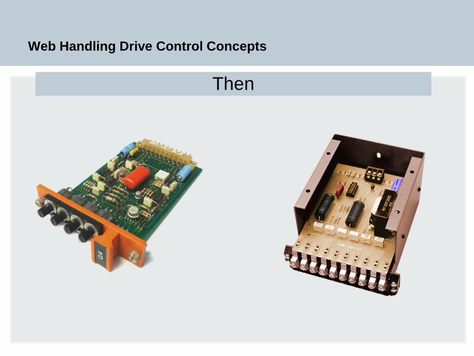
Web Handling Drive Control Concepts
Then
Restricted © Siemens Industry, Inc. 2013 All rights reserved.
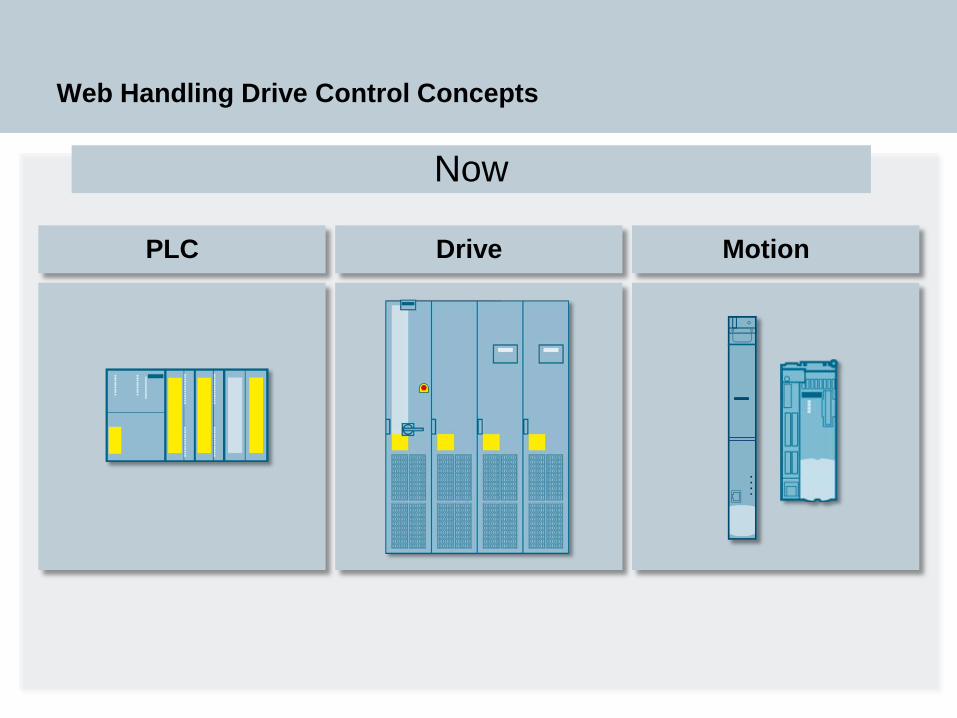
Web Handling Drive Control Concepts
PLC Drive Motion
Now
Restricted © Siemens Industry, Inc. 2013 All rights reserved.
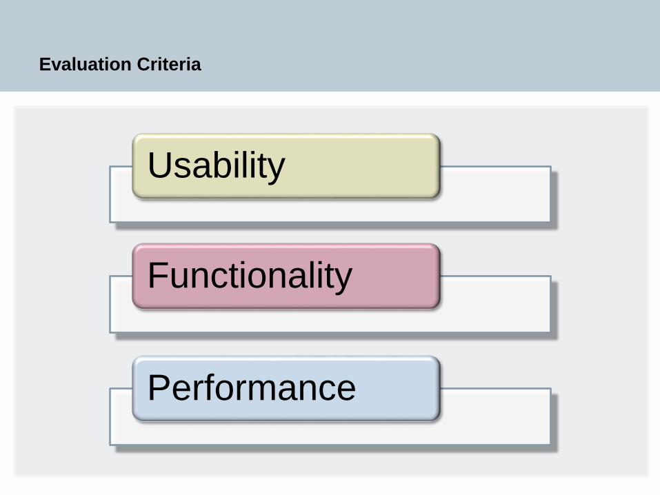
Evaluation Criteria
Usability
Functionality
Performance
Restricted © Siemens Industry, Inc. 2013 All rights reserved.
Evaluation
Usability
Functionality
Performance
Restricted © Siemens Industry, Inc. 2013 All rights reserved.
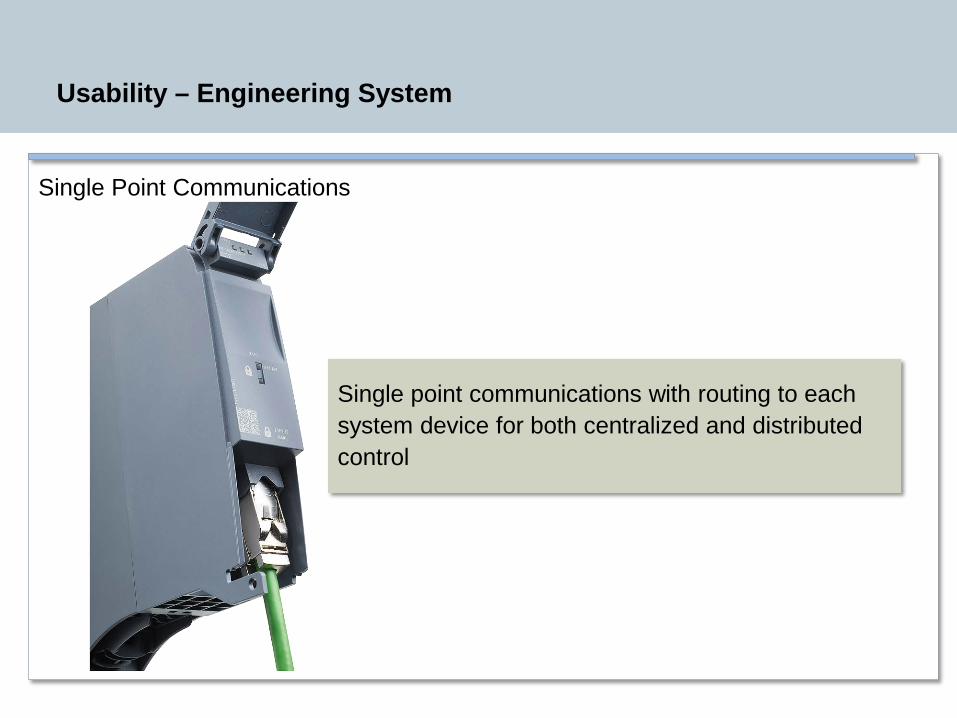
Usability – Engineering System
Single Point Communications
Single point communications with routing to each system device for both centralized and distributed control
Restricted © Siemens Industry, Inc. 2013 All rights reserved.
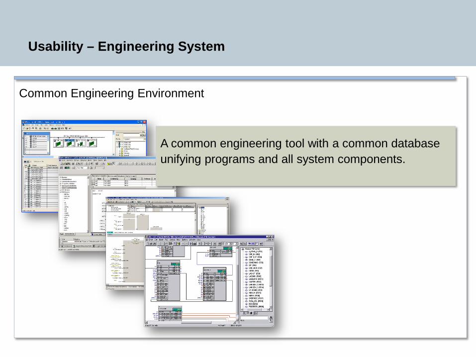
Usability – Engineering System
Common Engineering Environment
A common engineering tool with a common database unifying programs and all system components.
Restricted © Siemens Industry, Inc. 2013 All rights reserved.
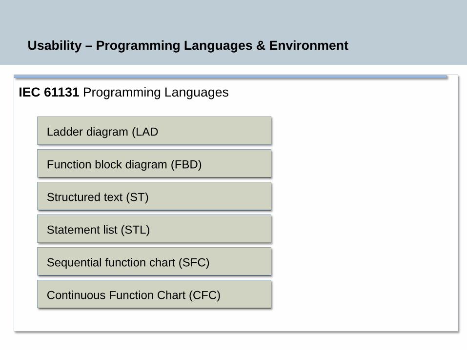
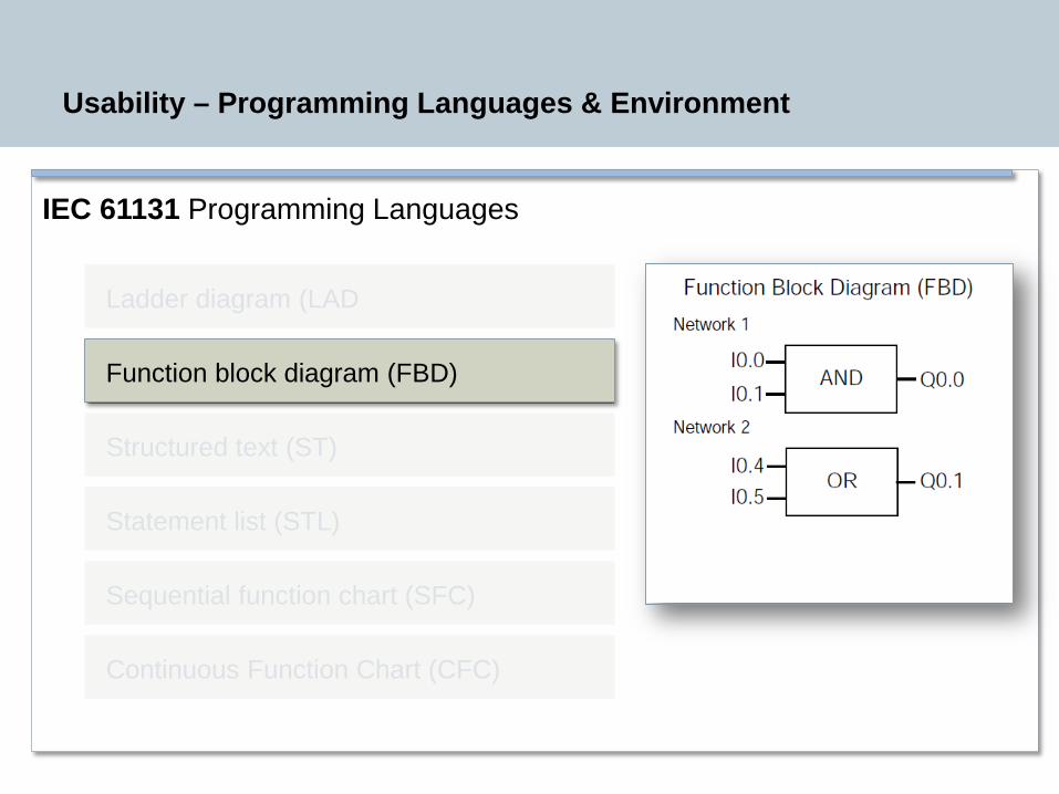
IEC 61131 Programming Languages
Usability – Programming Languages & Environment
Ladder diagram (LAD
Function block diagram (FBD)
Structured text (ST)
Statement list (STL)
Sequential function chart (SFC)
Continuous Function Chart (CFC)

Restricted © Siemens Industry, Inc. 2013 All rights reserved.
IEC 61131 Programming Languages
Usability – Programming Languages & Environment
Ladder diagram (LAD
Function block diagram (FBD)
Structured text (ST)
Statement list (STL)
Sequential function chart (SFC)
Continuous Function Chart (CFC)
Restricted © Siemens Industry, Inc. 2013 All rights reserved.
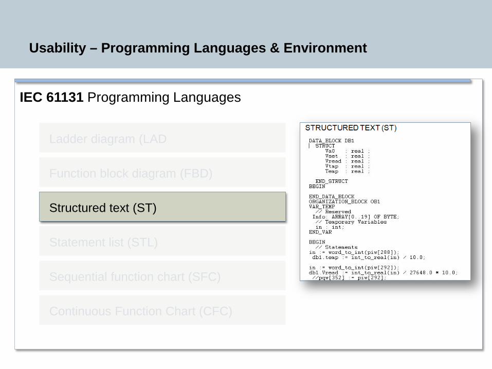
IEC 61131 Programming Languages
Usability – Programming Languages & Environment
Ladder diagram (LAD
Function block diagram (FBD)
Structured text (ST)
Statement list (STL)
Sequential function chart (SFC)
Continuous Function Chart (CFC)
Restricted © Siemens Industry, Inc. 2013 All rights reserved.
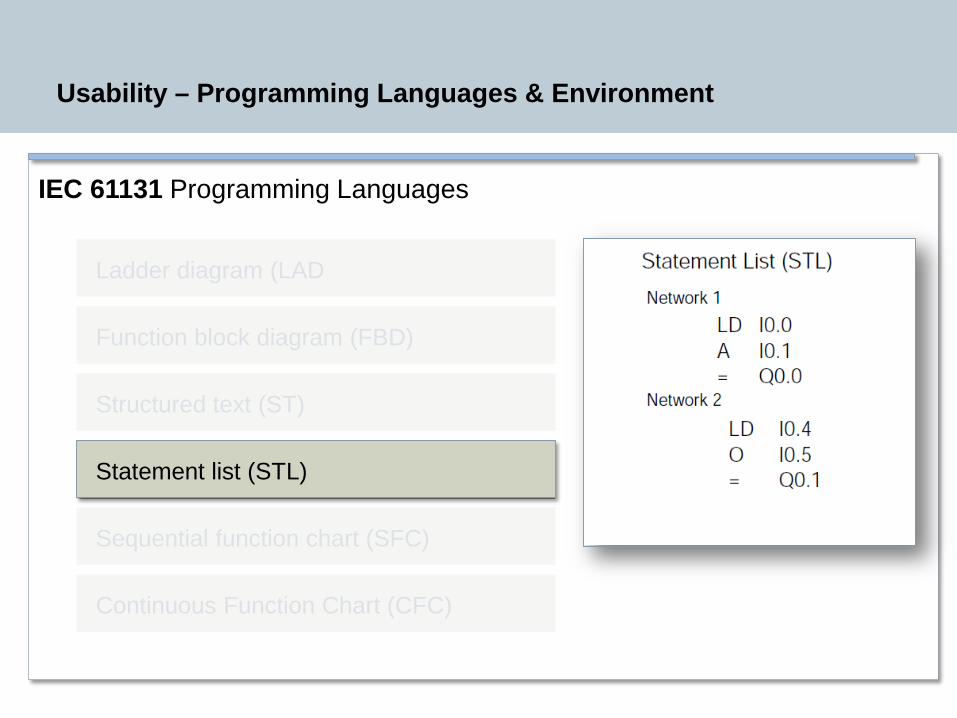
IEC 61131 Programming Languages
Usability – Programming Languages & Environment
Ladder diagram (LAD
Function block diagram (FBD)
Structured text (ST)
Statement list (STL)
Sequential function chart (SFC)
Continuous Function Chart (CFC)
Restricted © Siemens Industry, Inc. 2013 All rights reserved.
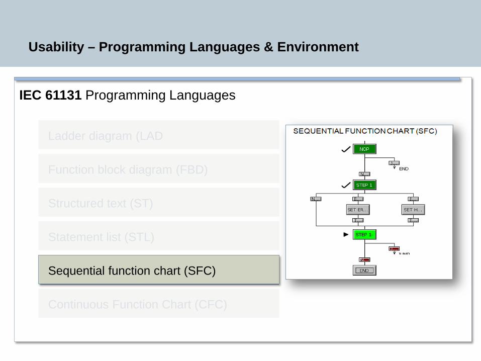
IEC 61131 Programming Languages
Usability – Programming Languages & Environment
Ladder diagram (LAD
Function block diagram (FBD)
Structured text (ST)
Statement list (STL)
Sequential function chart (SFC)
Continuous Function Chart (CFC)
Restricted © Siemens Industry, Inc. 2013 All rights reserved.
IEC 61131 Programming Languages
Usability – Programming Languages & Environment
Ladder diagram (LAD
Function block diagram (FBD)
Structured text (ST)
Statement list (STL)
Sequential function chart (SFC)
Continuous Function Chart (CFC)
Restricted © Siemens Industry, Inc. 2013 All rights reserved.
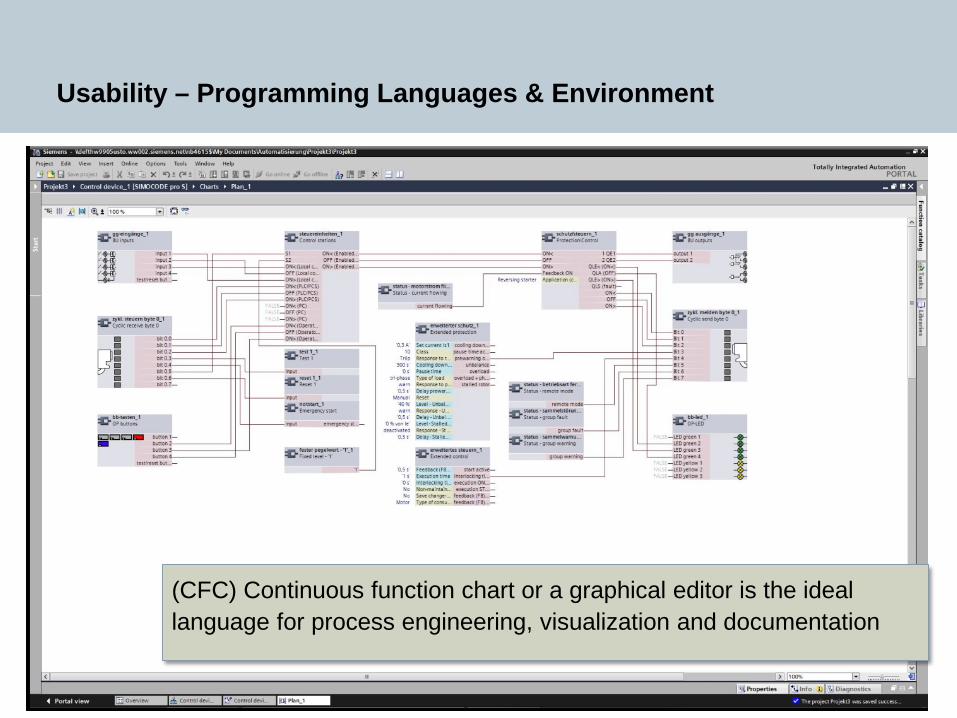
Usability – Programming Languages & Environment
(CFC) Continuous function chart or a graphical editor is the ideal language for process engineering, visualization and documentation
Restricted © Siemens Industry, Inc. 2013 All rights reserved.
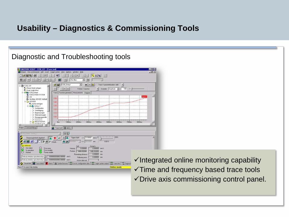
Usability – Diagnostics & Commissioning Tools
Diagnostic and Troubleshooting tools
Integrated online monitoring capabilityTime and frequency based trace tools Drive axis commissioning control panel.
Restricted © Siemens Industry, Inc. 2013 All rights reserved.
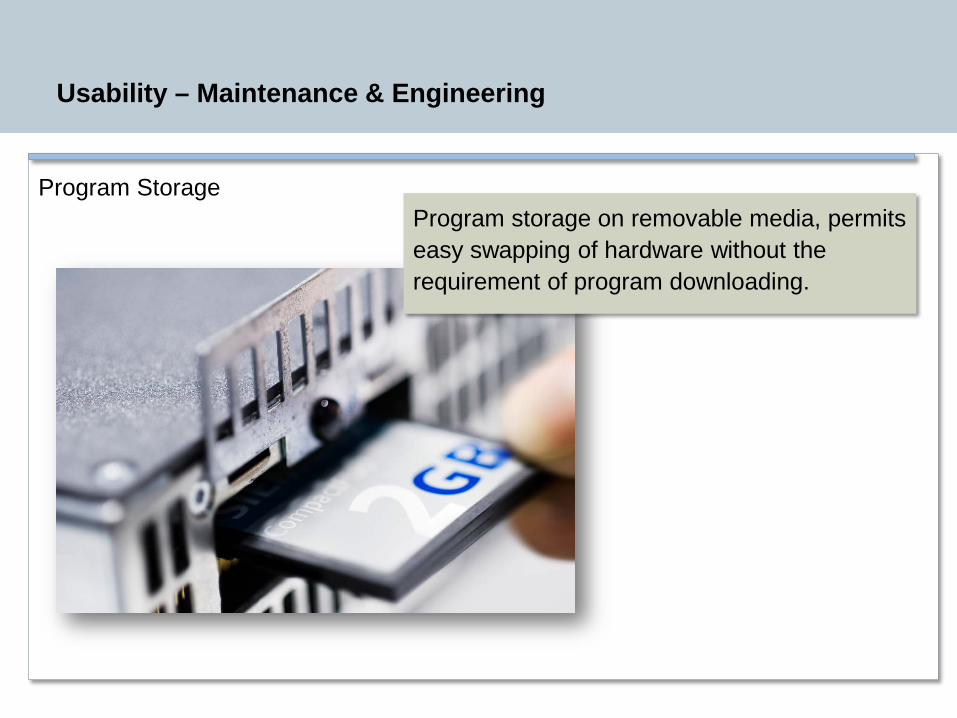
Usability – Maintenance & Engineering
Program StorageProgram storage on removable media, permits easy swapping of hardware without the requirement of program downloading.
Restricted © Siemens Industry, Inc. 2013 All rights reserved.
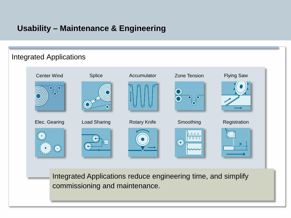
Integrated Applications
Usability – Maintenance & Engineering
Integrated Applications reduce engineering time, and simplify commissioning and maintenance.
Center Wind Splice Accumulator Zone Tension Flying Saw
Elec. Gearing Load Sharing Rotary Knife Smoothing Registration

Restricted © Siemens Industry, Inc. 2013 All rights reserved.
Evaluation
Usability
Functionality
Performance
Restricted © Siemens Industry, Inc. 2013 All rights reserved.
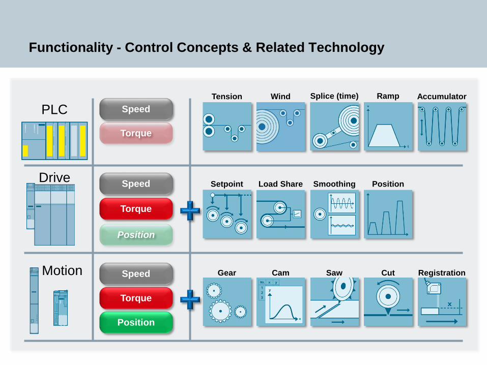
Functionality - Control Concepts & Related Technology
PLCSplice (time)
Position
Torque
Position
Speed
Torque
Speed
Torque
SpeedDrive
Motion
RampTension Wind Accumulator
Setpoint Load Share Smoothing Position
Gear Cam Saw Cut Registration

Restricted © Siemens Industry, Inc. 2013 All rights reserved.
Functionality - PLC Based Architecture (Centralized)
HMI
Drive Section #1 Drive Section #2Machine & Web Control
PLC
Network
Restricted © Siemens Industry, Inc. 2013 All rights reserved.
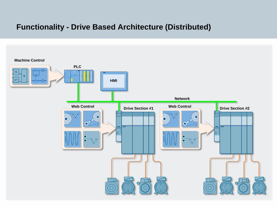
Functionality - Drive Based Architecture (Distributed)
PLC
HMI
Drive Section #1 Drive Section #2
Network
Machine Control
Web Control Web Control

Restricted © Siemens Industry, Inc. 2013 All rights reserved.
Functionality - Motion Control Architecture (Centralized)
Machine Control
Web Control
PLC
HMI
Network
Drive Section #1 Drive Section #2
Restricted © Siemens Industry, Inc. 2013 All rights reserved.
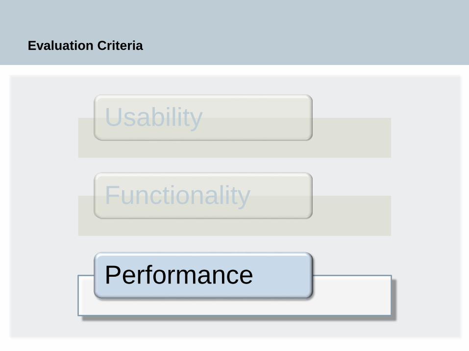
Evaluation Criteria
Usability
Functionality
Performance
Restricted © Siemens Industry, Inc. 2013 All rights reserved.
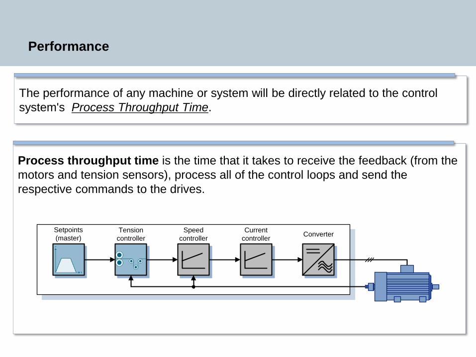
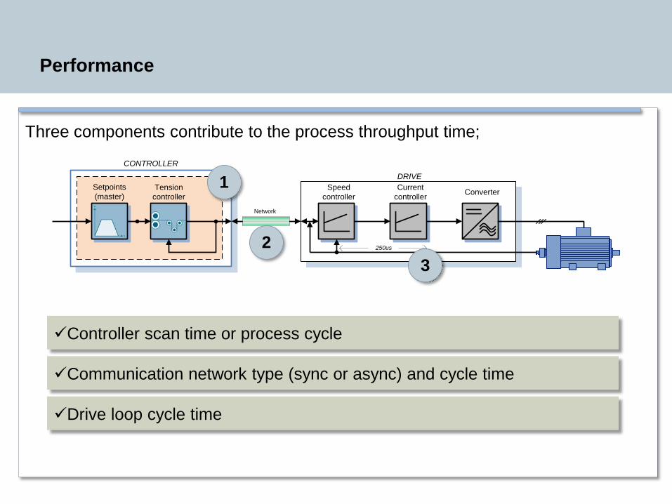
Process throughput time is the time that it takes to receive the feedback (from the motors and tension sensors), process all of the control loops and send the respective commands to the drives.
Performance
The performance of any machine or system will be directly related to the control system's Process Throughput Time.
Speed controller
Current controller ConverterTension
controllerSetpoints (master)
Restricted © Siemens Industry, Inc. 2013 All rights reserved.
Performance
Three components contribute to the process throughput time;
Speed controller
Current controller Converter
DRIVETension controller
Setpoints (master)
Network
250us
CONTROLLER
Controller scan time or process cycle
Communication network type (sync or async) and cycle time
Drive loop cycle time
1
23
Restricted © Siemens Industry, Inc. 2013 All rights reserved.
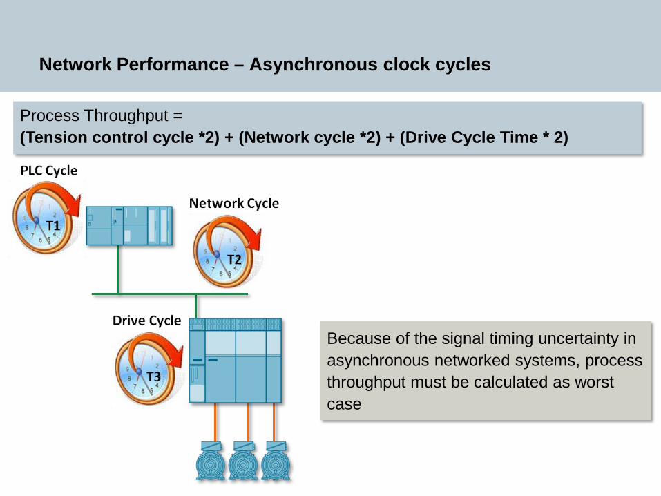
Network Performance – Asynchronous clock cycles
Process Throughput = (Tension control cycle *2) + (Network cycle *2) + (Drive Cycle Time * 2)
Because of the signal timing uncertainty in asynchronous networked systems, process throughput must be calculated as worst case
Restricted © Siemens Industry, Inc. 2013 All rights reserved.
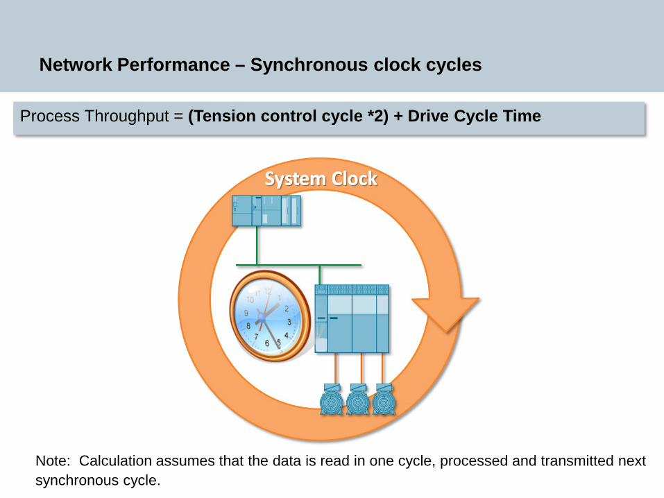
Network Performance – Synchronous clock cycles
Process Throughput = (Tension control cycle *2) + Drive Cycle Time
Note: Calculation assumes that the data is read in one cycle, processed and transmitted next synchronous cycle.
Restricted © Siemens Industry, Inc. 2013 All rights reserved.
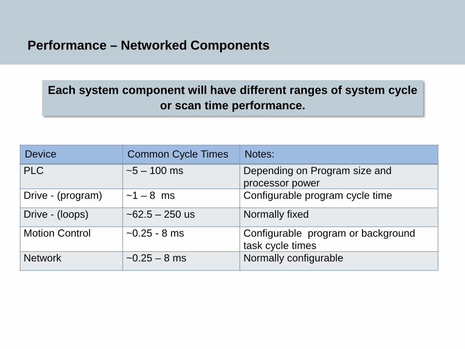
Performance – Networked Components
Each system component will have different ranges of system cycle or scan time performance.
Device Common Cycle Times Notes:PLC ~5 – 100 ms Depending on Program size and
processor power Drive - (program) ~1 – 8 ms Configurable program cycle time
Drive - (loops) ~62.5 – 250 us Normally fixed
Motion Control ~0.25 - 8 ms Configurable program or background task cycle times
Network ~0.25 – 8 ms Normally configurable
Restricted © Siemens Industry, Inc. 2013 All rights reserved.
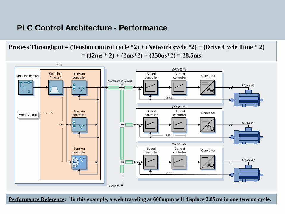
PLC Control Architecture - Performance
Speed controller
Current controller Converter
DRIVE #1PLC
Machine control Tension controller
Speed controller
Current controller Converter
DRIVE #2Tension controller
Setpoints (master)
Asynchronous Network
Speed controller
Current controller ConverterTension
controller
DRIVE #3
To Drive n ...
12ms
2ms
250us
250us
250us
Motor #1
Motor #2
Motor #3
Web Control
Process Throughput = (Tension control cycle *2) + (Network cycle *2) + (Drive Cycle Time * 2)= (12ms * 2) + (2ms*2) + (250us*2) = 28.5ms
Performance Reference: In this example, a web traveling at 600mpm will displace 2.85cm in one tension cycle.
Restricted © Siemens Industry, Inc. 2013 All rights reserved.
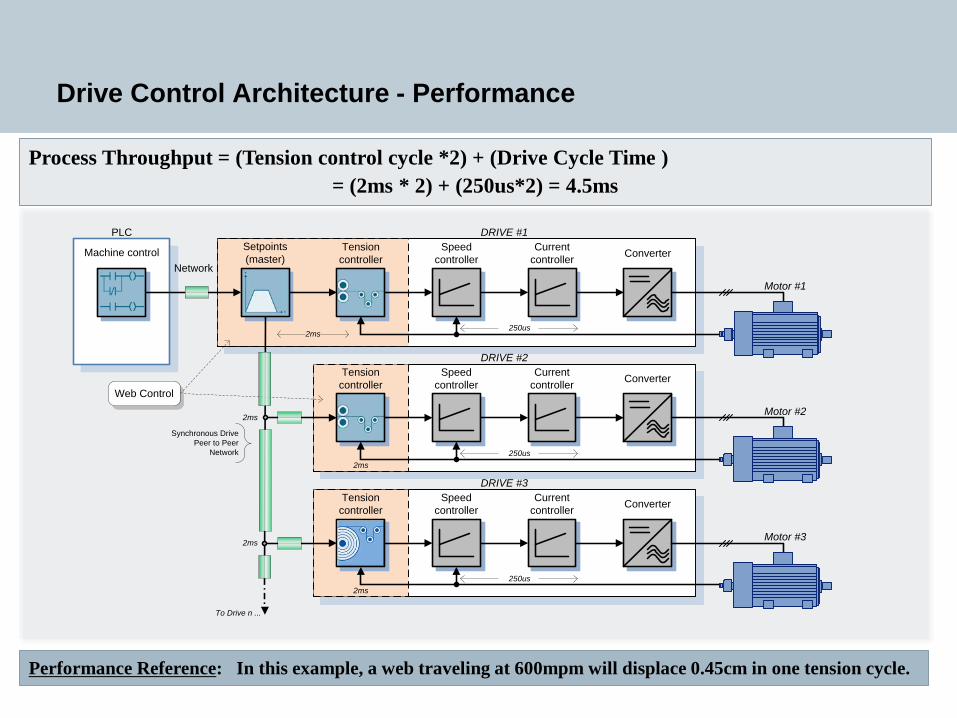
Drive Control Architecture - Performance
Speed controller
Current controller Converter
DRIVE #1PLC
Machine controlNetwork
Tension controller
Speed controller
Current controller Converter
DRIVE #2Tension controller
Setpoints (master)
Synchronous Drive Peer to Peer
Network
Speed controller
Current controller ConverterTension
controller
DRIVE #3
To Drive n ...
2ms
2ms
2ms
2ms
2ms
250us
250us
250us
Motor #1
Motor #2
Motor #3
Web Control
Process Throughput = (Tension control cycle *2) + (Drive Cycle Time )= (2ms * 2) + (250us*2) = 4.5ms
Performance Reference: In this example, a web traveling at 600mpm will displace 0.45cm in one tension cycle.
Restricted © Siemens Industry, Inc. 2013 All rights reserved.
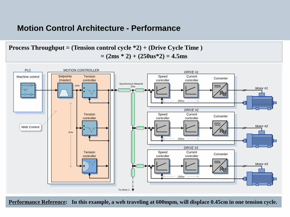
Motion Control Architecture - Performance
PLC
Speed controller
Current controller Converter
DRIVE #1MOTION CONTROLLER
Machine control Tension controller
Speed controller
Current controller Converter
DRIVE #2Tension controller
Setpoints (master)
Synchronous Network
Speed controller
Current controller ConverterTension
controller
DRIVE #3
To Drive n ...
2ms 2ms
2ms
250us
250us
250us
Motor #1
Motor #2
Motor #3
Web Control
Process Throughput = (Tension control cycle *2) + (Drive Cycle Time )= (2ms * 2) + (250us*2) = 4.5ms
Performance Reference: In this example, a web traveling at 600mpm, will displace 0.45cm in one tension cycle.
Restricted © Siemens Industry, Inc. 2013 All rights reserved.
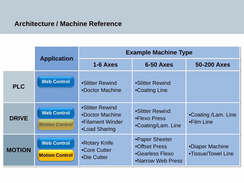
Architecture / Machine Reference
ApplicationExample Machine Type
1-6 Axes
PLC
DRIVE
MOTION
6-50 Axes 50-200 Axes
•Slitter Rewind•Doctor Machine
•Slitter Rewind•Coating Line
•Slitter Rewind•Doctor Machine•Filament Winder•Load Sharing
•Slitter Rewind•Flexo Press •Coating/Lam. Line
•Coating /Lam. Line•Film Line
•Rotary Knife•Core Cutter•Die Cutter
•Paper Sheeter•Offset Press•Gearless Flexo•Narrow Web Press
•Diaper Machine•Tissue/Towel Line
Web Control
Motion Control
Web Control
Web Control
Motion Control
Restricted © Siemens Industry, Inc. 2013 All rights reserved.
Technology Trends
Integrated Web Server
Restricted © Siemens Industry, Inc. 2013 All rights reserved.
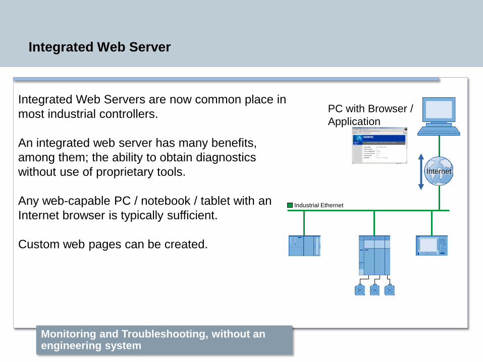
Integrated Web Server
Integrated Web Servers are now common place in most industrial controllers.
An integrated web server has many benefits, among them; the ability to obtain diagnostics without use of proprietary tools.
Any web-capable PC / notebook / tablet with an Internet browser is typically sufficient.
Custom web pages can be created.
Monitoring and Troubleshooting, without an engineering system
Industrial Ethernet
Internet
PC with Browser / Application

Restricted © Siemens Industry, Inc. 2013 All rights reserved.
Integrated Web Server
Custom Web Pages
Restricted © Siemens Industry, Inc. 2013 All rights reserved.
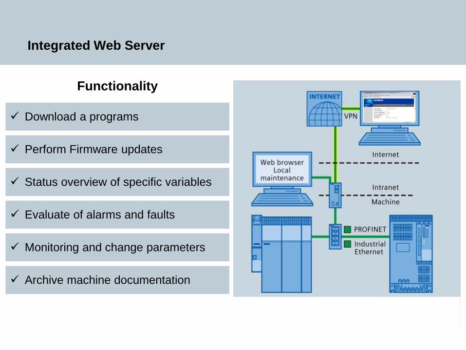
Integrated Web Server
Functionality
Download a programs
Perform Firmware updates
Status overview of specific variables
Evaluate of alarms and faults
Monitoring and change parameters
Archive machine documentation

Restricted © Siemens Industry, Inc. 2013 All rights reserved.
Web Handling Drive Control Concepts
Then

Restricted © Siemens Industry, Inc. 2013 All rights reserved.
Web Handling Drive Control Concepts
PLC Drive Motion
Now
Restricted © Siemens Industry, Inc. 2013 All rights reserved.
Conclusions
Considering the optimum control architecture can be an interesting challenge. Each of the detailed systems has its benefits and limitations.
PLC based solutions offer a medium level of performance with a high level of usability.
Drive base solutions offer a higher level of performance through their distributed control structure. They typically have high usability through optimum engineering tools.
With the continuing demands on production speeds, product quality and considering the general trend of motion based control, integrated drive and motion are not only well suited but becoming common place in the industrial landscape. The concepts and benefits of motion control based solutions can be extremely attractive for both new converting lines and retrofits.
Restricted © Siemens Industry, Inc. 2013 All rights reserved.
Thank You
William GilbertSiemens Industry, Inc.
5300 Triangle ParkwayNorcross, GA 30092
Phone: +1 (770) 625-5658Mobile: +1 (678) 314-4222E-mail: [email protected]
Website: www.usa.siemens.com/converting
Answers for Converting