bioretenion - tennessee stormwater trainingtnpermanentstormwater.org/manual/14 chapter 5.4.6...
TRANSCRIPT

5.4.6 BioretentionDescription: Bioretention areas are vegetated, shallowsurface depressions that use the interaction ofplants, soil, and microorganisms to store, treat, andreduce runoff volume, and to reduce the flow rateof stormwater runoff. Bioretention areas are generallyflat and include engineered or modified soils thatallow drainage of stormwater through soils. Duringstorms, runoff temporarily ponds 6 to 12 inchesabove the mulch layer and then rapidly filtersthrough the bed.
5.4.6 –Bioretenti
on
Tennessee Permanent Stormwater Management and Design Guidance Manual 141
Figure 1: Bioretention capture water from parkinglot in Powell, TN (Source: The SMART Center).
Key Design Criteria:• Min. filter media depth: 18-24 inches.
Recommended maximum: 36 inches• Ponding depth: 6-12 inches• Length of shortest flow path/length: 0.3
Site Constraints:• Depth: 2 feet to water table / bedrock• Steep slopes: <20% or terraced to slow flow. • Media permeability: ≤ 0.5in/h or needs
underdrain • Hotspots: Needs to use impermeable
bottom liner and an underdrain system. • Min. distance requirement from:
Water supply wells: 100 feetSurface water: 30 feet
Maintenance:• Monitor sediment accumulation and
remove as necessary• Inspect channel and repair any eroding
surfaces or vegetation• Ensure vegetation is well established• Remove debris from any inlet and outlet
structures.
Advantages:• Reduces runoff volume, peak discharge rate,
TSS, pollutant, and runoff temperature.• Creates habitat and improves aesthetic.• Flexible dimensions to fit conditions • Excellent retrofit capability.
Disadvantages:• Built on areas that are generally level (or
graded level). • Steep slopes may require larger footprint to
create level grading. • Vegetation and soils must be protected from
damage and compaction. • Maintenance is required to maintain both
performance and aesthetics.
Design Checklist:• Determine whether an Infiltration or
filtration Design is best for the site based onpermeability or other site limitations.
• Check bioretention sizing guidance.• Design bioretention in accordance with
design criteria and typical details.• Submit plans for review.

n1. Design
1.1 Suggested Applications and ScaleBioretention can be applied in most soils or topography, since runoff simply percolates through anengineered soil bed. Consider locating bioretention areas in places that are generally “not used” such astraffic islands; between parked cars in parking lots; along edges of public playgrounds, school yards, andplazas; in courtyards; and in place of traditional landscape planting areas. The following site-specificconditions should be considered:
• Select location to prevent vegetation damage and soil compaction from pedestrian traffic orunintended vehicle compaction. Ideal locations are often located to the side or downhill of highvehicle or pedestrian traffic areas. If necessary, provide for pedestrian passage and maintenanceaccess.
• Locate bioretention areas: − Close to the source of runoff. − To capture runoff from impervious areas and highly compacted pervious areas such as athletic
fields and lawns. − To capture smaller drainage areas. If necessary, use several connected bioretention areas to
address larger areas.
The most important design factor to consider when applyingbioretention to development sites is the scale at which itwill be applied, as follows:
• Micro-Bioretention or Rain Gardens. These aresmall, distributed practices designed to treat runofffrom small areas, such as individual rooftops,driveways and other on-lot features in single-family detached residential developments. Inflow istypically sheet flow, or can be concentrated flow withenergy dissipation, when located at downspouts.
• Bioretention Basins. These are structures treatingparking lots and/or commercial rooftops, usuallyin commercial or institutional areas. Inflow can beeither sheetflow or concentrated flow. Bioretentionbasins may also be distributed throughout aresidential subdivision, but ideally they should belocated in common areas or within drainageeasements, to treat a combination of roadway andlot runoff.
• Urban Bioretention. These are structures such asexpanded tree pits, curb extensions, and foundationplanters located in ultra-urban developed areassuch as city streetscapes.
5.4.
6 –
Bior
eten
tion
142 Tennessee Permanent Stormwater Management and Design Guidance Manual
Figures 2 & 3: roof leaders are directlyconnected to the bed. Bioretention that
manages runoff from a parking lot(Source: The SMART Center).
5.4.6 –Bioretenti
on
Tennessee Permanent Stormwater Management and Design Guidance Manual 143
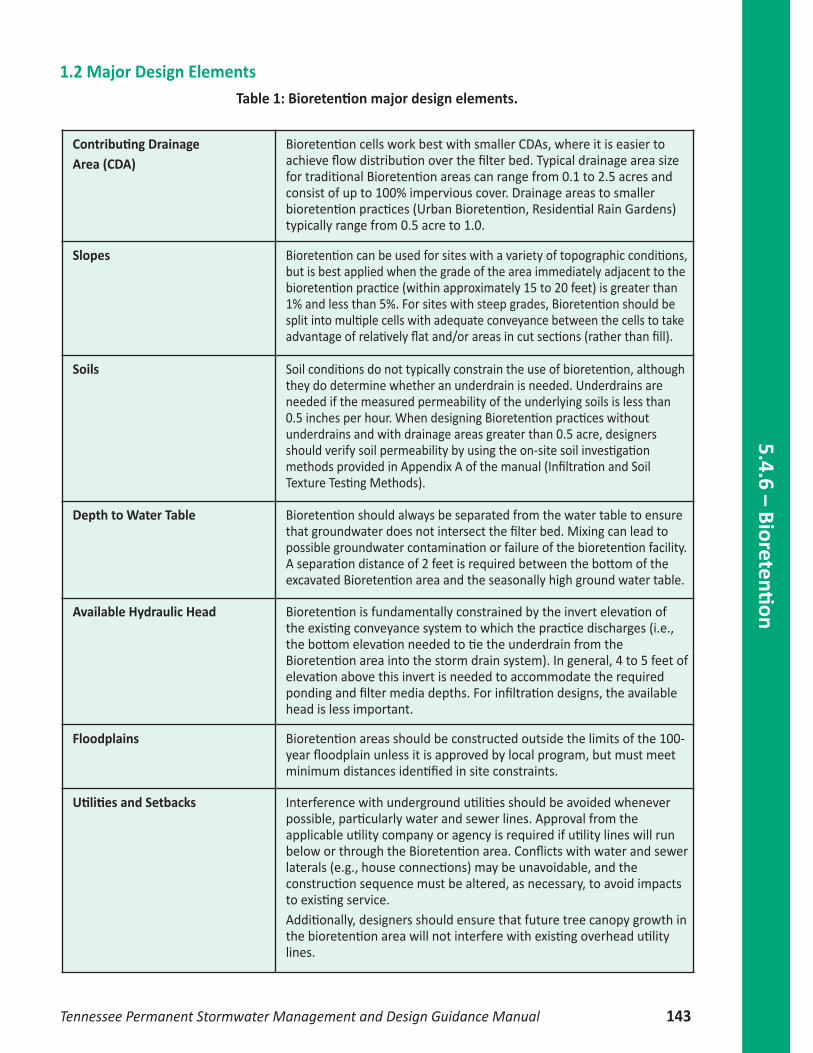
Contributing Drainage Area (CDA)
Bioretention cells work best with smaller CDAs, where it is easier toachieve flow distribution over the filter bed. Typical drainage area sizefor traditional Bioretention areas can range from 0.1 to 2.5 acres andconsist of up to 100% impervious cover. Drainage areas to smallerbioretention practices (Urban Bioretention, Residential Rain Gardens)typically range from 0.5 acre to 1.0.
Slopes Bioretention can be used for sites with a variety of topographic conditions,but is best applied when the grade of the area immediately adjacent to thebioretention practice (within approximately 15 to 20 feet) is greater than1% and less than 5%. For sites with steep grades, Bioretention should besplit into multiple cells with adequate conveyance between the cells to takeadvantage of relatively flat and/or areas in cut sections (rather than fill).
Soils Soil conditions do not typically constrain the use of bioretention, althoughthey do determine whether an underdrain is needed. Underdrains areneeded if the measured permeability of the underlying soils is less than0.5 inches per hour. When designing Bioretention practices withoutunderdrains and with drainage areas greater than 0.5 acre, designersshould verify soil permeability by using the on-site soil investigationmethods provided in Appendix A of the manual (Infiltration and SoilTexture Testing Methods).
Depth to Water Table Bioretention should always be separated from the water table to ensurethat groundwater does not intersect the filter bed. Mixing can lead topossible groundwater contamination or failure of the bioretention facility.A separation distance of 2 feet is required between the bottom of theexcavated Bioretention area and the seasonally high ground water table.
Available Hydraulic Head Bioretention is fundamentally constrained by the invert elevation ofthe existing conveyance system to which the practice discharges (i.e.,the bottom elevation needed to tie the underdrain from theBioretention area into the storm drain system). In general, 4 to 5 feet ofelevation above this invert is needed to accommodate the requiredponding and filter media depths. For infiltration designs, the availablehead is less important.
Floodplains Bioretention areas should be constructed outside the limits of the 100-year floodplain unless it is approved by local program, but must meetminimum distances identified in site constraints.
Utilities and Setbacks Interference with underground utilities should be avoided wheneverpossible, particularly water and sewer lines. Approval from theapplicable utility company or agency is required if utility lines will runbelow or through the Bioretention area. Conflicts with water and sewerlaterals (e.g., house connections) may be unavoidable, and theconstruction sequence must be altered, as necessary, to avoid impactsto existing service.Additionally, designers should ensure that future tree canopy growth inthe bioretention area will not interfere with existing overhead utilitylines.
1.2 Major Design ElementsTable 1: Bioretention major design elements.

5.4.
6 –
Bior
eten
tion
144 Tennessee Permanent Stormwater Management and Design Guidance Manual
Setbacks To avoid the risk of seepage, do not allow bioretention areas to behydraulically connected to structure foundations or pavement. Setbacksto structures and roads vary, based on the scale of the bioretentiondesign. At a minimum, bioretention basins should be located a horizontaldistance of 100 feet from any water supply well (50 feet if the bioretentionis lined), 50 feet from septic systems (25 feet if the bioretention is lined),and at least 5 feet from down-gradient wet utility lines. Dry utility linessuch as gas, electric, cable and telephone may cross under bioretentionareas if they are double-cased.
No Irrigation or Baseflow The planned bioretention area should not receive baseflow, irrigationwater, chlorinated wash-water or other such non-stormwater flowsthat are not stormwater runoff.
Hotspot Land Uses Runoff from hotspot land uses should not be treated with infiltratingbioretention (i.e., constructed without an underdrain) unlesspretreatment has been provided. An impermeable bottom liner and anunderdrain system must be employed when bioretention is used toreceive and treat hotspot runoff.
1.3 Design Criteria
Figure 4: Flow diagram.
1.3.1 Pre‐treatmentPre-treatment of runoff entering bioretention areas is necessary to trap coarse sediment particles beforethey reach and prematurely clog the filter bed. Pre-treatment measures must be designed to evenlyspread runoff across the entire width of the bioretention area. Several pre-treatment measures arefeasible, depending on the scale of the bioretention practice and whether it receives sheet flow, shallowconcentrated flow or deeper concentrated flows. The following are appropriate pretreatment options:
• Pre‐treatment Cells (channel flow): Similar to a forebay, this cell is located at piped inlets orcurb cuts leading to the bioretention area and consists of an energy dissipater sized for theexpected rates of discharge. It has a storage volume equivalent to at least 15% of the totalTreatment Volume (inclusive) with a 2:1 length-to-width ratio. The cell may be formed by awooden or stone check dam or an earthen or rock berm. Pretreatment cells do not needunderlying engineered soil media, in contrast to the main bioretention cell.
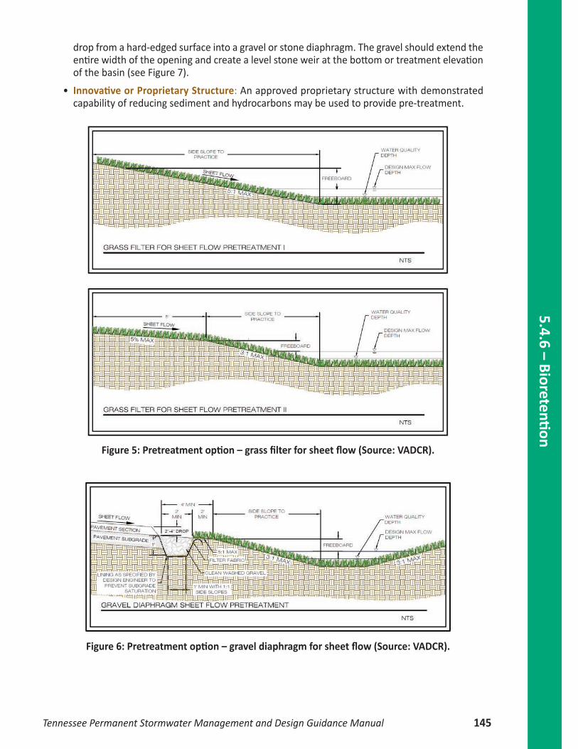
• Grass Filter Strips (sheet flow): Grass filter strips extend from the edge of pavement to thebottom of the bioretention basin at a 5:1 slope or flatter. Alternatively, provide a combined 5feet of grass filter strip at a maximum 5% (20:1) slope and 3:1 or flatter side slopes on thebioretention basin (see Figure 6).
• Gravel or Stone Diaphragms (sheet flow): A gravel diaphragm located at the edge of the pavementshould be oriented perpendicular to the flow path to pre-treat lateral runoff, with a 2 to 4 inchdrop. The stone must be sized according to the expected rate of discharge. (See Figure 6)
• Gravel or Stone Flow Spreaders (concentrated flow). The gravel flow spreader is located at curbcuts, downspouts, or other concentrated inflow points, and should have a 2 to 4 inch elevation
drop from a hard-edged surface into a gravel or stone diaphragm. The gravel should extend theentire width of the opening and create a level stone weir at the bottom or treatment elevationof the basin (see Figure 7).
• Innovative or Proprietary Structure: An approved proprietary structure with demonstratedcapability of reducing sediment and hydrocarbons may be used to provide pre-treatment.
Figure 5: Pretreatment option – grass filter for sheet flow (Source: VADCR).
Figure 6: Pretreatment option – gravel diaphragm for sheet flow (Source: VADCR).
5.4.6 –Bioretenti
on
Tennessee Permanent Stormwater Management and Design Guidance Manual 145

Figure 7: Pretreatment option – gravel flow spreader for concentrated flow (Source: VADCR).
1.3.2 Entrance/Flow conditionsCaptured runoff may enter a bioretention area in one of three ways:
a) Through dispersed surface flow such as along a depressed curb, lawn area, or edge of pavementas shown in Figures 8 and 9. Careful grading is essential to prevent concentrated flow pointsand potential erosion. For bioretention adjacent to existing impervious pavement, such as in aretrofit installation or modification to an existing site, it is recommended that the adjacentpavement be milled and repaved/replaced to provide a uniform edge and dispersed sheet flowinto the bioretention area.
Figure 8: bioretention to capture sheet flowfrom neighborhood in Knoxville TN
(Source: The SMART Center).
Figure 9: bioretention to capture runofffrom a parking lot in Powell TN(Source: The SMART Center).
5.4.
6 –
Bior
eten
tion
146 Tennessee Permanent Stormwater Management and Design Guidance Manual
b) Through a concentrated discharge location such as a trench drain, outlet pipe, or curb cut.Bioretention soils and mulch are highly erosive. Entrance velocities should not exceed 1 fpsunless designed with entrance measures to prevent erosion, such as:• Cobble splash blocks• Small level spreaders• Turf reinforcement materials
Supporting entrance velocity calculations are required for all concentrated surface discharges intobioretention areas.
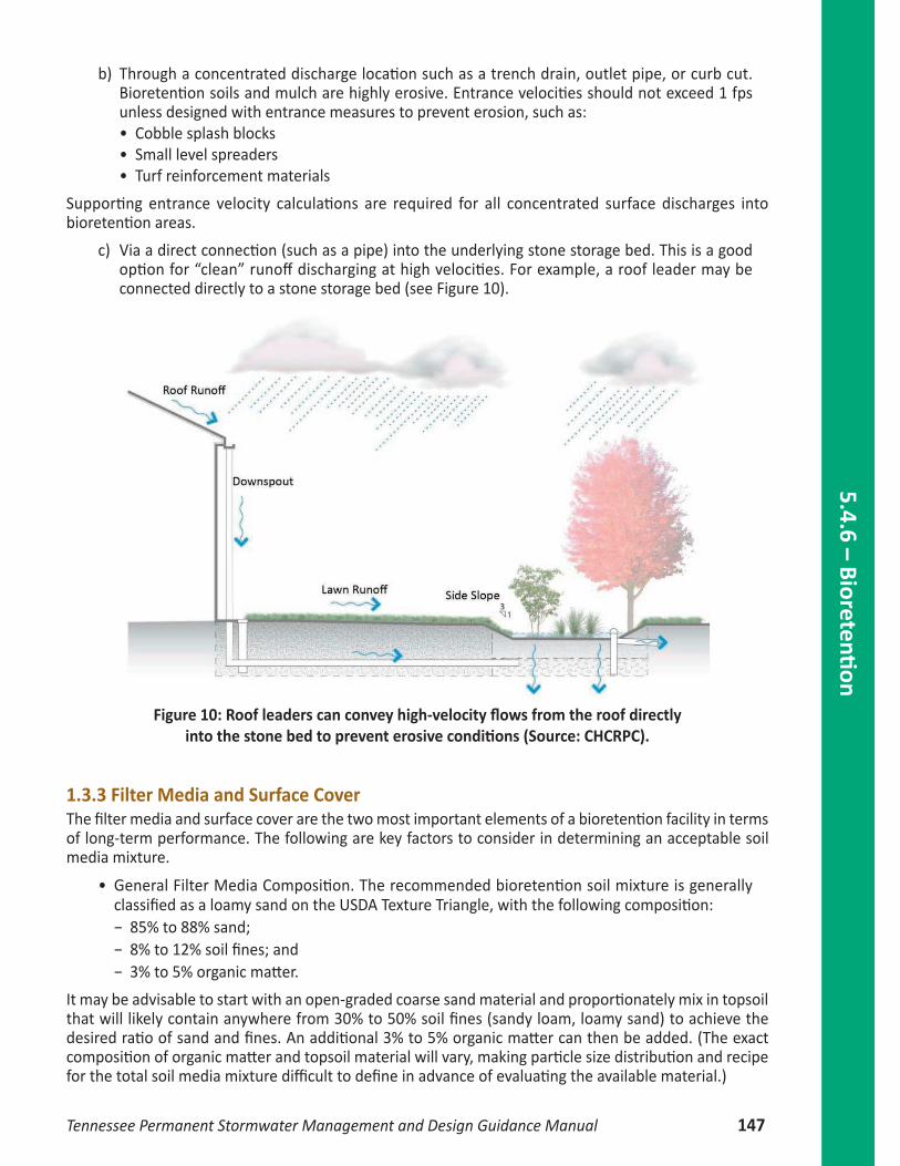
c) Via a direct connection (such as a pipe) into the underlying stone storage bed. This is a goodoption for “clean” runoff discharging at high velocities. For example, a roof leader may beconnected directly to a stone storage bed (see Figure 10).
Figure 10: Roof leaders can convey high-velocity flows from the roof directlyinto the stone bed to prevent erosive conditions (Source: CHCRPC).
1.3.3 Filter Media and Surface CoverThe filter media and surface cover are the two most important elements of a bioretention facility in termsof long-term performance. The following are key factors to consider in determining an acceptable soilmedia mixture.
• General Filter Media Composition. The recommended bioretention soil mixture is generallyclassified as a loamy sand on the USDA Texture Triangle, with the following composition: − 85% to 88% sand; − 8% to 12% soil fines; and − 3% to 5% organic matter.
It may be advisable to start with an open-graded coarse sand material and proportionately mix in topsoilthat will likely contain anywhere from 30% to 50% soil fines (sandy loam, loamy sand) to achieve thedesired ratio of sand and fines. An additional 3% to 5% organic matter can then be added. (The exactcomposition of organic matter and topsoil material will vary, making particle size distribution and recipefor the total soil media mixture difficult to define in advance of evaluating the available material.)
5.4.6 –Bioretenti
on
Tennessee Permanent Stormwater Management and Design Guidance Manual 147

• P‐Index. The P-Index provides a measure of soil phosphorus content and the risk of thatphosphorus moving through the soil media. The risk of phosphorus movement through a soil isinfluenced by several soil physical properties: texture, structure, total pore space, pore-size,pore distribution, and organic matter. A soil with a lot of fines will hold phosphorus while alsolimiting the movement of water. A soil that is sandy will have a high permeability, and willtherefore be less likely to hold phosphorus within the soil matrix. A primary factor in interpretingthe desired P-Index of a soil is the bulk density. Saxton et. al. (1986) estimated generalized bulkdensities and soil-water characteristics from soil texture. The expected bulk density of the loamysand soil composition described above should be in the range of 1.6 to 1.7 g/cu. cm. Therefore,the recommended range for bioretention soil P-index of between 10 and 30 corresponds to aphosphorus content range (mg of P to kg of soil) within the soil media of 7 mg/kg to 23 mg/kg.
• Cation Exchange Capacity (CEC).The CEC of a soil refers to the total amount of positively chargedelements that a soil can hold; it is expressed in milliequivalents per 100 grams (meq/100g) ofsoil. For agricultural purposes, these elements are the basic cations of calcium (Ca+2),magnesium (Mg+2), potassium (K+1) and sodium (Na+1) and the acidic cations of hydrogen(H+1) and aluminum (Al+3). The CEC of the soil is determined in part by the amount of clayand/or humus or organic matter present. Soils with CECs exceeding 10 are preferred for pollutantremoval. Increasing the organic matter content of any soil will help to increase the CEC, since italso holds cations like the clays.
• Infiltration Rate. The bioretention soil media should have a minimum infiltration rate of 0.5inches per hour (a proper soil mix will have an initial infiltration rate that is significantly higher).
• Depth. The standard minimum filter should be 24 inches for grass cells and 36 inches for shrubcells, and 18 to 24 inches for rain gardens or micro-bioretention. If trees are included in thebioretention planting plan, tree planting holes in the filter bed must be at least 4 feet deep toprovide enough soil volume for the root structure of mature trees. Use turf, perennials or shrubsinstead of trees to landscape shallower filter beds.
• Filter Media for Tree Planting Areas. A more organic filter media is recommended within theplanting holes for trees, with ratio of 50% sand, 30% top soil and 20% acceptable leaf compost.
• Mulch. A 2 to 3 inch layer of mulch on the surface of the filter bed enhances plant survival,suppresses weed growth, and pre-treats runoff before it reaches the filter media. Shredded,aged hardwood bark mulch makes a very good surface cover, as it retains a significant amountof nitrogen and typically will not float away. The use of woodchips, which may “float” shouldbe prohibited.
• Alternative to Mulch Cover. In some situations, designers may consider alternative surfacecovers such as turf, native groundcover, erosion control matting (coir or jute matting), riverstone, or pea gravel. The decision regarding the type of surface cover to use should be basedon function, cost and maintenance. Stone or gravel are not recommended in parking lotapplications, since they increase soil temperature and have low water holding capacity.
• Media for Turf Cover. One adaptation is to design the filter media primarily as a sand filter withorganic content only at the top. Leaf compost tilled into the top layers will provide organiccontent for the vegetative cover. If grass is the only vegetation, the ratio of compost may be reduced.
1.3.4 Soil Infiltration Rate TestingIn order to determine if an underdrain will be needed, one must measure the infiltration rate of subsoilsat the invert elevation of the bioretention area. The infiltration rate of subsoils must exceed 0.5 inch perhour in order to dispense with the underdrain requirement. Soil testing is not needed where anunderdrain is used.
5.4.
6 –
Bior
eten
tion
148 Tennessee Permanent Stormwater Management and Design Guidance Manual
1.3.5 Underdrain and Underground Storage LayerThe depth of the storage layer will depend on the target treatment and storage volumes needed to meetwater quality. However, the bottom of the storage layer must be at least 2 feet above the seasonally highwater table. The storage layer should consist of clean, washed #57 stone or an approved infiltrationmodule.
All bioretention basins should include observation wells. The observation wells should be tied into anyT’s or Y’s in the underdrain system, and should extend upwards to be flush with the surface, with a ventedcap. In addition, cleanout pipes should be provided if the contributing drainage area exceeds 1 acre.
1.3.5.1 Internal Water Storage Zones (IWS) An Internal Water Storage Zone (IWS) can be created by the addition of an elbow in the underdrain pipingat a 90º angle vertically perpendicular to the horizontal underdrain, either in retrofit conditions or in newinstallations. This up-turned elbow on underdrains can force water to remain longer in the bottom of thecell, creating a saturated internal water storage zone (IWS). If this zone remains saturated long enough,anaerobic conditions are created, promoting denitrification and increased N removal (Passeport et al., 2009).
There are several benefits to using upturned elbows and IWS. The IWS works for both pollutant and peakflow reduction as anaerobic conditions can be created to increase nitrogen removal. It also allows morewater to infiltrate into the surrounding soils. If an upturned elbow is installed correctly in sufficientlypermeable soils, it may only rarely generate outflows. The use of upturned elbows and an IWS is especiallybeneficial in the areas where surrounding sandy soils can be ideal for infiltration, reducing outflows andsurface water runoff. There can be a thermal benefit to IWS use as water is pulled from the coolest zoneat the bottom of the cell. This is especially beneficial for temperature reductions in trout waters. Finally,there is often a cost benefit for using upturned elbows, both for new installations and retrofits. In newinstallations, there is a cost-savings associated with installation since the invert of the outlet is not asdeep. Often with IWS there can be less trenching and fewer materials associated with using it. In retrofits,upturned elbows can be cheaply added to existing Bioretention cells where increased N & P removal ratesare needed. Additionally, cells with IWS can be added as retrofits even in areas with restricted outlet depth.
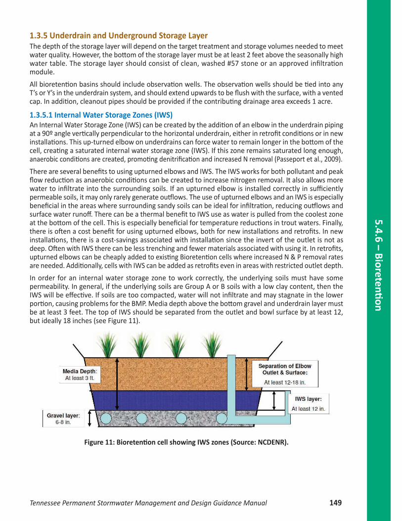
In order for an internal water storage zone to work correctly, the underlying soils must have somepermeability. In general, if the underlying soils are Group A or B soils with a low clay content, then theIWS will be effective. If soils are too compacted, water will not infiltrate and may stagnate in the lowerportion, causing problems for the BMP. Media depth above the bottom gravel and underdrain layer mustbe at least 3 feet. The top of IWS should be separated from the outlet and bowl surface by at least 12,but ideally 18 inches (see Figure 11).
Figure 11: Bioretention cell showing IWS zones (Source: NCDENR).
5.4.6 –Bioretenti
on
Tennessee Permanent Stormwater Management and Design Guidance Manual 149

1.3.6 Overflow/ConveyanceFor On‐line bioretention:
An overflow structure should always be incorporated into on-line designs to safely convey larger stormsthrough the bioretention area. The following criteria apply to overflow structures:
• The overflow associated with the 2 and 10 year design storms should be controlled so that velocitiesare non-erosive at the outlet point (i.e., to prevent downstream erosion).
• Common overflow systems within bioretention practices consist of an inlet structure, wherethe top of the structure is placed at the maximum water surface elevation of the bioretention area,which is typically 6 to 12 inches above the surface of the filter bed (6 inches is the preferredponding depth).
• The overflow capture device (typically a yard inlet) should be scaled to the application – thismay be a landscape grate inlet or a commercial-type structure.
• The filter bed surface should generally be flat so the bioretention area fills up like a bathtub.
Figure 12: Bioretention units can be designed using an overflow device so that waterin excess of the treatment volume overflows to a filter strip. This example shows
a filter strip, though it is not required for every design (Source: NCDENR).
5.4.
6 –
Bior
eten
tion
150 Tennessee Permanent Stormwater Management and Design Guidance Manual

5.4.6 –Bioretenti
on
Tennessee Permanent Stormwater Management and Design Guidance Manual 151
Off‐line bioretention:
Off-line designs are preferred (see Figure 13). One common approach is to create an alternate flow pathat the inflow point into the structure such that when the maximum ponding depth is reached, theincoming flow is diverted past the facility. In this case, the higher flows do not pass over the filter bedand through the facility, and additional flow is able to enter as the ponding water filtrates through thesoil media.
Figure 13: Typical Details for Off-Line Bioretention (Source: VADCR).
1.3.7 Freeboard It is recommended that bioretention areas include a minimum of 6 inches of freeboard above the overflowroute.
1.3.8 Bioretention Planting PlansA landscaping plan must be provided for each bioretention area. Minimum plan elements shall includethe proposed bioretention template to be used, delineation of planting areas, the planting plan, includingthe size, the list of planting stock, sources of plant species, and the planting sequence, including post-nursery care and initial maintenance requirements. It is highly recommended that the planting plan beprepared by a qualified landscape architect, in order to tailor the planting plan to the site-specific conditions.Tennessee native plant species are preferred over non-native species, but some ornamental species maybe used for landscaping effect if they are not aggressive or invasive. Some popular native species thatwork well in bioretention areas and are commercially available can be found in Appendix D. The six mostcommon bioretention templates are as follows:
• Turf. This option is typically restricted to on-lot micro-bioretention applications, such as a frontyard rain garden. Grass species should be selected that have dense cover, are relatively slowgrowing, and require the least mowing and chemical inputs (e.g., fine fescue, tall fescue).
• Perennial garden. This option uses herbaceous plants and native grasses to create a gardeneffect with seasonal cover. It may be employed in both micro-scale and small scale bioretentionapplications. This option is attractive, but it requires more maintenance in the form of weeding.
• Perennial garden with shrubs. This option provides greater vertical form by mixing native shrubsand perennials together in the bioretention area. This option is frequently used when the filterbed is too shallow to support tree roots. Shrubs should have a minimum height of 30 inches.
• Tree, shrub and herbaceous plants. This is the traditional landscaping option for bioretention.It produces the most natural effect, and it is highly recommended for bioretention basinapplications. The landscape goal is to simulate the structure and function of a native forest plantcommunity.
• Turf and tree. This option is a lower maintenance version of the tree-shrub-herbaceous optionwhere the mulch layer is replaced by turf cover. Trees are planted within larger mulched islandsto prevent damage during mowing operations.
• Herbaceous meadow. This is another lower maintenance approach that focuses on the herbaceouslayer and may resemble a wildflower with Joe Pye Weed, Ironweed, sedges, grasses, etc.). Thegoal is to establish a more natural look that may be appropriate if the facility is located in alower maintenance area (e.g., further from buildings and parking lots). Shrubs and trees maybe incorporated around the perimeter. Erosion control matting can be used in lieu of theconventional mulch layer.
5.4.
6 –
Bior
eten
tion
152 Tennessee Permanent Stormwater Management and Design Guidance Manual
5.4.6 –Bioretenti
on
Tennessee Permanent Stormwater Management and Design Guidance Manual 153
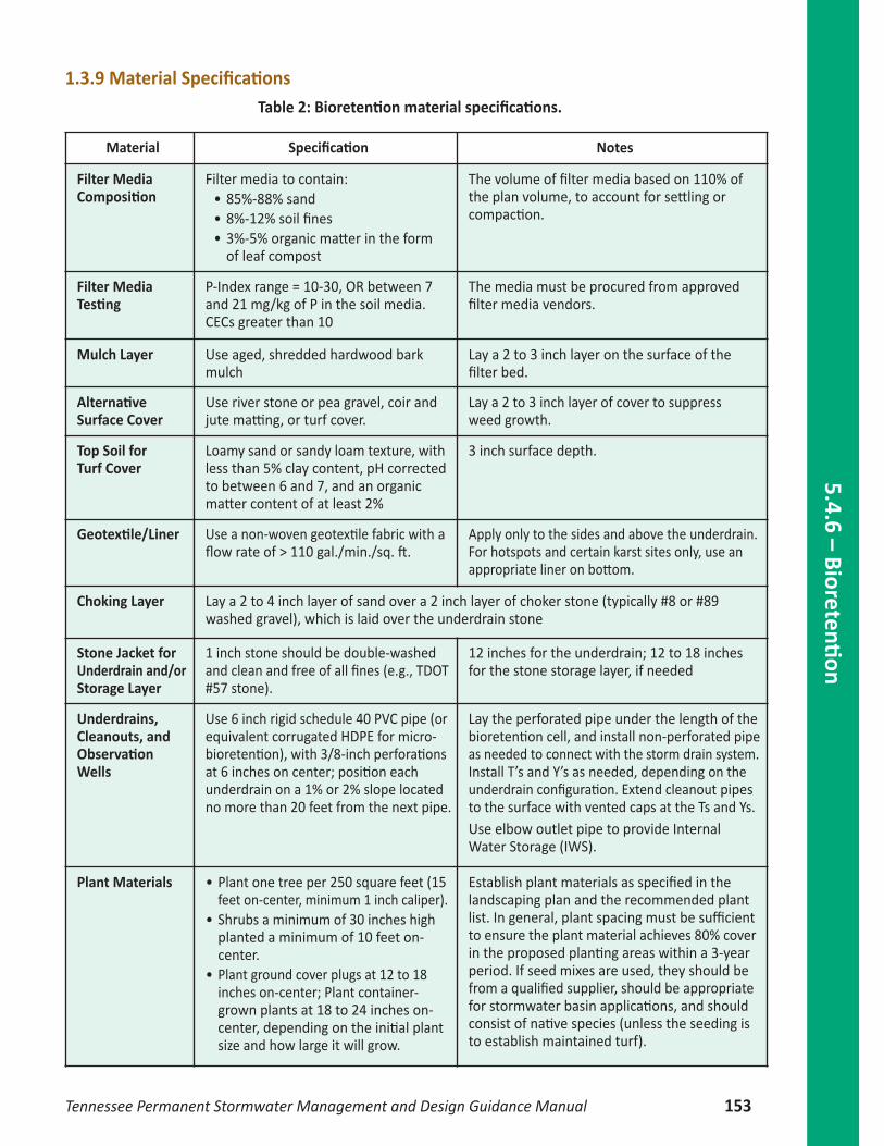
Material Specification Notes
Filter MediaComposition
Filter media to contain:• 85%-88% sand• 8%-12% soil fines• 3%-5% organic matter in the form
of leaf compost
The volume of filter media based on 110% ofthe plan volume, to account for settling orcompaction.
Filter MediaTesting
P-Index range = 10-30, OR between 7and 21 mg/kg of P in the soil media.CECs greater than 10
The media must be procured from approvedfilter media vendors.
Mulch Layer Use aged, shredded hardwood barkmulch
Lay a 2 to 3 inch layer on the surface of thefilter bed.
AlternativeSurface Cover
Use river stone or pea gravel, coir andjute matting, or turf cover.
Lay a 2 to 3 inch layer of cover to suppressweed growth.
Top Soil forTurf Cover
Loamy sand or sandy loam texture, withless than 5% clay content, pH correctedto between 6 and 7, and an organicmatter content of at least 2%
3 inch surface depth.
Geotextile/Liner Use a non-woven geotextile fabric with aflow rate of > 110 gal./min./sq. ft.
Apply only to the sides and above the underdrain.For hotspots and certain karst sites only, use anappropriate liner on bottom.
Choking Layer Lay a 2 to 4 inch layer of sand over a 2 inch layer of choker stone (typically #8 or #89washed gravel), which is laid over the underdrain stone
Stone Jacket forUnderdrain and/orStorage Layer
1 inch stone should be double-washedand clean and free of all fines (e.g., TDOT#57 stone).
12 inches for the underdrain; 12 to 18 inchesfor the stone storage layer, if needed
Underdrains,Cleanouts, andObservationWells
Use 6 inch rigid schedule 40 PVC pipe (orequivalent corrugated HDPE for micro-bioretention), with 3/8-inch perforationsat 6 inches on center; position eachunderdrain on a 1% or 2% slope locatedno more than 20 feet from the next pipe.
Lay the perforated pipe under the length of thebioretention cell, and install non-perforated pipeas needed to connect with the storm drain system.Install T’s and Y’s as needed, depending on theunderdrain configuration. Extend cleanout pipesto the surface with vented caps at the Ts and Ys.Use elbow outlet pipe to provide InternalWater Storage (IWS).
Plant Materials • Plant one tree per 250 square feet (15feet on-center, minimum 1 inch caliper).
• Shrubs a minimum of 30 inches highplanted a minimum of 10 feet on-center.
• Plant ground cover plugs at 12 to 18inches on-center; Plant container-grown plants at 18 to 24 inches on-center, depending on the initial plantsize and how large it will grow.
Establish plant materials as specified in thelandscaping plan and the recommended plantlist. In general, plant spacing must be sufficientto ensure the plant material achieves 80% coverin the proposed planting areas within a 3-yearperiod. If seed mixes are used, they should befrom a qualified supplier, should be appropriatefor stormwater basin applications, and shouldconsist of native species (unless the seeding isto establish maintained turf).
1.3.9 Material SpecificationsTable 2: Bioretention material specifications.

1.3.10 Overview
Table 3: Bioretention design criteria.
5.4.
6 –
Bior
eten
tion
154 Tennessee Permanent Stormwater Management and Design Guidance Manual
Micro‐bioretention (rain garden). MaxCDA: 0.5 acres, 25% impervious cover.
Bioretention filter & basin area. Max CDA:2.5 acres.
Sizing Filter surface area (sq. ft.) = 3% of thecontributing drainage area (CDA).
Surface Area (sq. ft.) = Total runoff volume – thevolume reduced by an upstream SCM(s)/StorageDepth1
MaximumPonding Depth
6 inches 6 - 12 inches2
Filter MediaDepth
Min: 18 inches; max: 24 inches Min: 24 inches for grass; 36 inches for shrubs;max: 6 feet
Media / surfacecover
Mixed on-site or supplied by vendor. Media mix tested for an acceptable phosphorus index(P-Index) of between 10 and 30, OR Between 7 and 21 mg/kg of P in the soil media
Sub‐soil testing Not needed if an underdrain is used;Min infiltration rate > 0.5 inch/hourin order to remove the underdrainrequirement.
Not needed if an underdrain used; Mininfiltration rate ≥ 2 inch/hour in orderto remove the underdrain requirement.
Underdrain Corrugated HDPE or equivalent Schedule 40 PVC with clean-outs
Clean‐outs Not needed Needed
Inflow Sheet flow or roof leader Sheet flow, curb cuts, trench drains, orconcentrated flow.
Geometry Length of shortest flow path/Overall length = 0.3
Pretreatment External (leaf screens, grass filter strip,energy dissipater, etc.)
A pretreatment cell, grass filter strip, graveldiaphragm, gravel flow spreader, or anotherapproved (manufactured) pre-treatmentstructure.
Buildingsetbacks3
10 feet down-gradient; 25 feet up-gradient from building
0 to 0.5 acre CDA = 10 feet if down-gradientfrom building; 50 feet if up-gradient. 0.5 to 2.5acre CDA = 25 feet if down-gradient frombuilding; 100 feet if up-gradient.
Planting Plan A planting template to include turf, herbaceousvegetation, shrubs, and/or trees to achievesurface area coverage of at least 80% within3 years.
1. Storage depth is the sum of the Void Ratio (Vr) of the soil media and gravel layers multiplied by their respective depths,plus the surface ponding depth. .
2. A ponding depth of 6 inches is preferred. Ponding depths greater than 6 inches will require a specific planting plan toensure appropriate plant selection.
3. These are recommendations for simple building foundations. If an in-ground basement or other special conditions exist,the design should be reviewed by a licensed engineer. Also, a special footing or drainage design may be used to justifya reduction of the setbacks noted above.

Figure 14: Typical bioretention section with void ratios for volume computations (Source: CHCRPC).
1.4 Calculations1.4.1 Practice Dimensions using TNRRATSizing the practice dimension can be done using the Tennessee Stormwater Runoff Reduction AssessmentTool (TNRRAT). The tool allows users to iteratively size their SCM(s) to meet the goal of 1-inch runoffreduction and 80% pollutant removal. The inputs needed for the tool are:
− Location− Area per management types and surface management types (such as impervious, bare soil,
good forest, bioretention, etc)− Soil texture− Depth surface to restrictive layer− Type of layer materials− Depth of layer materials
1.4.2 Practice Dimensions using other methodAlthough using the TNRRAT is recommended, designer and engineers are welcomed to use other methodsto size bioretention and other SCMs.
1.4.2.1Runoff Volume Use standard engineering methods to calculate runoff volume.
1.4.2.2 Surface AreaThe size and surface area of a bioretention system maybe a function of the drainage area that will discharge tothe bioretention system. It is important not to concentratetoo much flow in one location. A basic rule-of-thumb isto design a bioretention system with a surface area thatis a ratio of the impervious and compacted pervious areasdraining to it. A 1:10 ratio of surface area to imperviousdrainage area base on design rainfall depth can be usedto estimate a bioretention area.
Vr = 0.25
6”-12” MAX. PONDING DEPTH
Vr = 0.4
5.4.6 –Bioretenti
on
Tennessee Permanent Stormwater Management and Design Guidance Manual 155
Inputs needed for calculation:
− Location− Size of CDA− Cover type− Approximation of practice
surface area and practice depth− Void ratio values
1.4.2.3 Design DepthWith an estimate of the required bioretention area and runoff volume, the designer can estimate thedepth of water, soil, and stone storage. The recommended depths for surface water storage, soil storage, and stone storage are:
• Surface Water Storage Depth: − 6 inches maximum in high-use areas (along streets, at schools, in public landscapes, etc.) − 12 inches in less used areas (away from frequent public access)
• Bioretention Soil Depth: Between 12 and 36 inches • Gravel storage Depth: Between 12 and 36 inches
Void ratios (Vr) are generally: • 0.20 for bioretention soils • 0.40 for clean-washed aggregate such as AASHTO No.3 • 0.85 to 0.95 for manufactured storage units depending on manufacturer
Storage depth:
[Soil depth x Soil media Vr] + [Gravel depth x Gravel Vr] + [Surface storage depth x surface storage](Equation 1)
Example: (2 ft. x 0.25) + (1 ft. x 0.40) + (0.5 x 1.0) = 1.40 ft.
1.4.2.4 Practice VolumeStorage Volume (ft3) = Surface Water Volume + Soil Storage Volume + Stone Storage Volume
(Equation 2)
Where: − Surface Water Volume: Available surface water storage between soil
surface and overflow structure (always equal to or less than 12 inches).The designer should consider the bed side slopes when estimatingvolume. Surface water volume = Surface water area (ft2) x Surfacewater depth (ft) x Void Ratio
− Soil Storage Volume (ft3) = Soil Area (ft2) x Soil depth (ft) below overflow x Void ratio − Gravel Storage Volume (ft3) = Gravel area (ft2) x Gravel Depth (ft) below overflow x Void Ratio
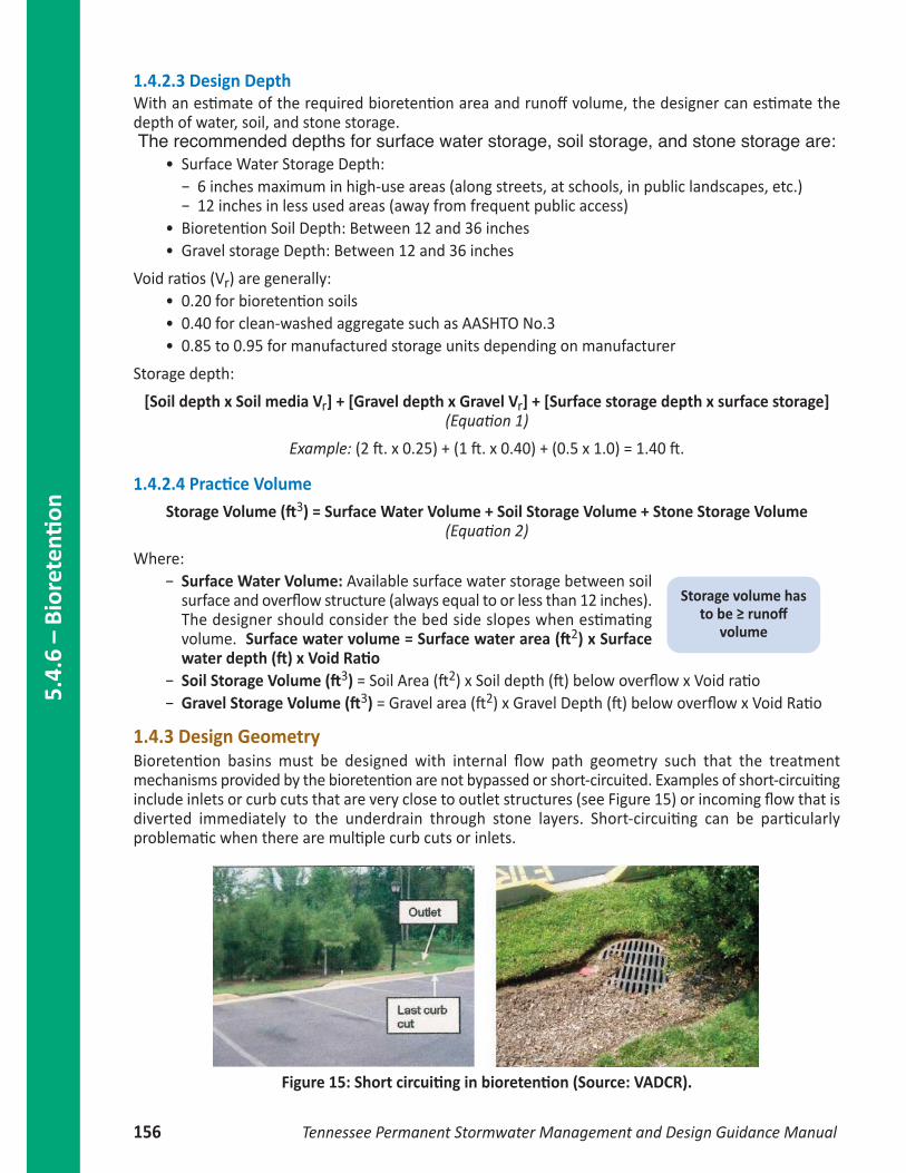
1.4.3 Design GeometryBioretention basins must be designed with internal flow path geometry such that the treatmentmechanisms provided by the bioretention are not bypassed or short-circuited. Examples of short-circuitinginclude inlets or curb cuts that are very close to outlet structures (see Figure 15) or incoming flow that isdiverted immediately to the underdrain through stone layers. Short-circuiting can be particularlyproblematic when there are multiple curb cuts or inlets.
5.4.
6 –
Bior
eten
tion
156 Tennessee Permanent Stormwater Management and Design Guidance Manual
Storage volume hasto be ≥ runoff
volume
Figure 15: Short circuiting in bioretention (Source: VADCR).
5.4.6 –Bioretenti
on
Tennessee Permanent Stormwater Management and Design Guidance Manual 157
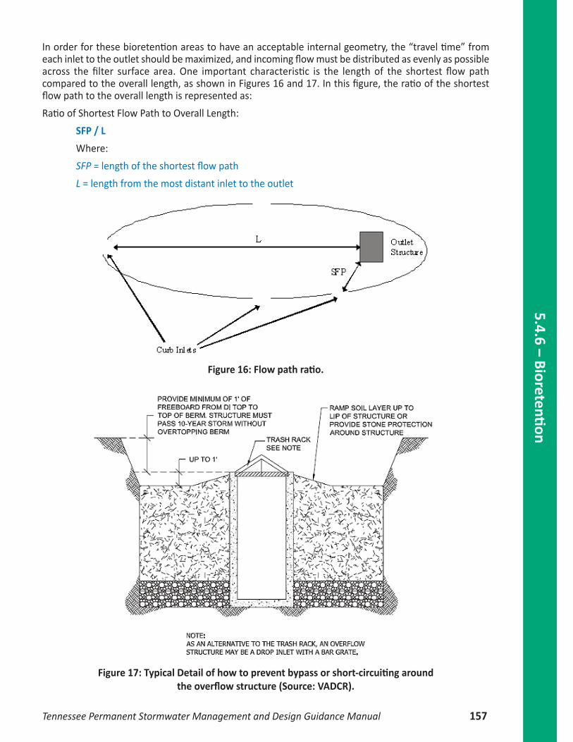
In order for these bioretention areas to have an acceptable internal geometry, the “travel time” fromeach inlet to the outlet should be maximized, and incoming flow must be distributed as evenly as possibleacross the filter surface area. One important characteristic is the length of the shortest flow pathcompared to the overall length, as shown in Figures 16 and 17. In this figure, the ratio of the shortestflow path to the overall length is represented as:
Ratio of Shortest Flow Path to Overall Length:
SFP / L
Where:
SFP = length of the shortest flow path
L = length from the most distant inlet to the outlet
Figure 16: Flow path ratio.
Figure 17: Typical Detail of how to prevent bypass or short-circuiting around the overflow structure (Source: VADCR).
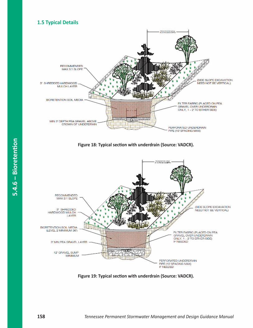
1.5 Typical Details
Figure 18: Typical section with underdrain (Source: VADCR).
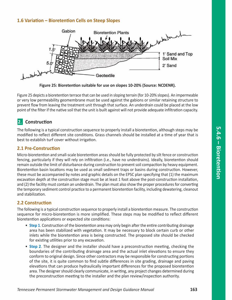
Figure 19: Typical section with underdrain (Source: VADCR).
5.4.
6 –
Bior
eten
tion
158 Tennessee Permanent Stormwater Management and Design Guidance Manual

Figure 20: Residential Rooftop Treatment – Plan View (Source: WVDEP).
Figure 21: Residential Rooftop Disconnection to downstream raingarden –Bioretention without an underdrain (Source: VADCR).
INFILTRATION AREA
BIORETENTION OR OTHER TREATMENT PRACTICE
5.4.6 –Bioretenti
on
Tennessee Permanent Stormwater Management and Design Guidance Manual 159

Figure 22: Bioretention with an underdrain (Source: VADCR).
5.4.
6 –
Bior
eten
tion
160 Tennessee Permanent Stormwater Management and Design Guidance Manual

Figure 23: Typical Detail of bioretention with additional surface ponding (Source: VADCR).
5.4.6 –Bioretenti
on
Tennessee Permanent Stormwater Management and Design Guidance Manual 161

Figure 24: Typical Detail of bioretention with the upper shelf of an extended detention storage (Source: VADCR).
5.4.
6 –
Bior
eten
tion
162 Tennessee Permanent Stormwater Management and Design Guidance Manual
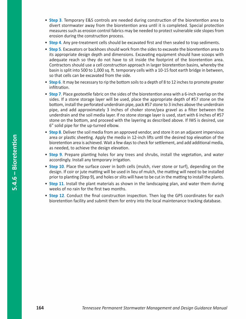
1.6 Variation – Bioretention Cells on Steep Slopes
Figure 25: Bioretention suitable for use on slopes 10-20% (Source: NCDENR).
Figure 25 depicts a bioretention terrace that can be used in sloping terrain (for 10-20% slopes). An impermeableor very low permeability geomembrane must be used against the gabions or similar retaining structure toprevent flow from leaving the treatment unit through that surface. An underdrain could be placed at the lowpoint of the filter if the native soil that the unit is built against will not provide adequate infiltration capacity.
n2. Construction
The following is a typical construction sequence to properly install a bioretention, although steps may bemodified to reflect different site conditions. Grass channels should be installed at a time of year that isbest to establish turf cover without irrigation.
2.1 Pre‐ConstructionMicro-bioretention and small-scale bioretention areas should be fully protected by silt fence or constructionfencing, particularly if they will rely on infiltration (i.e., have no underdrains). Ideally, bioretention shouldremain outside the limit of disturbance during construction to prevent soil compaction by heavy equipment.Bioretention basin locations may be used as small sediment traps or basins during construction. However,these must be accompanied by notes and graphic details on the EPSC plan specifying that (1) the maximumexcavation depth at the construction stage must be at least 1 foot above the post-construction installation,and (2) the facility must contain an underdrain. The plan must also show the proper procedures for convertingthe temporary sediment control practice to a permanent bioretention facility, including dewatering, cleanoutand stabilization.
2.2 ConstructionThe following is a typical construction sequence to properly install a bioretention measure. The constructionsequence for micro-bioretention is more simplified. These steps may be modified to reflect differentbioretention applications or expected site conditions:
• Step 1. Construction of the bioretention area may only begin after the entire contributing drainagearea has been stabilized with vegetation. It may be necessary to block certain curb or otherinlets while the bioretention area is being constructed. The proposed site should be checkedfor existing utilities prior to any excavation.
• Step 2. The designer and the installer should have a preconstruction meeting, checking theboundaries of the contributing drainage area and the actual inlet elevations to ensure theyconform to original design. Since other contractors may be responsible for constructing portionsof the site, it is quite common to find subtle differences in site grading, drainage and pavingelevations that can produce hydraulically important differences for the proposed bioretentionarea. The designer should clearly communicate, in writing, any project changes determined duringthe preconstruction meeting to the installer and the plan review/inspection authority.
5.4.6 –Bioretenti
on
Tennessee Permanent Stormwater Management and Design Guidance Manual 163
• Step 3. Temporary E&S controls are needed during construction of the bioretention area todivert stormwater away from the bioretention area until it is completed. Special protectionmeasures such as erosion control fabrics may be needed to protect vulnerable side slopes fromerosion during the construction process.
• Step 4. Any pre-treatment cells should be excavated first and then sealed to trap sediments. • Step 5. Excavators or backhoes should work from the sides to excavate the bioretention area to
its appropriate design depth and dimensions. Excavating equipment should have scoops withadequate reach so they do not have to sit inside the footprint of the bioretention area.Contractors should use a cell construction approach in larger bioretention basins, whereby thebasin is split into 500 to 1,000 sq. ft. temporary cells with a 10-15 foot earth bridge in between,so that cells can be excavated from the side.
• Step 6. It may be necessary to rip the bottom soils to a depth of 8 to 12 inches to promote greaterinfiltration.
• Step 7. Place geotextile fabric on the sides of the bioretention area with a 6-inch overlap on thesides. If a stone storage layer will be used, place the appropriate depth of #57 stone on thebottom, install the perforated underdrain pipe, pack #57 stone to 3 inches above the underdrainpipe, and add approximately 3 inches of choker stone/pea gravel as a filter between theunderdrain and the soil media layer. If no stone storage layer is used, start with 6 inches of #57stone on the bottom, and proceed with the layering as described above. If IWS is desired, use6” solid pipe for the up-turned elbow.
• Step 8. Deliver the soil media from an approved vendor, and store it on an adjacent imperviousarea or plastic sheeting. Apply the media in 12-inch lifts until the desired top elevation of thebioretention area is achieved. Wait a few days to check for settlement, and add additional media,as needed, to achieve the design elevation.
• Step 9. Prepare planting holes for any trees and shrubs, install the vegetation, and wateraccordingly. Install any temporary irrigation.
• Step 10. Place the surface cover in both cells (mulch, river stone or turf), depending on thedesign. If coir or jute matting will be used in lieu of mulch, the matting will need to be installedprior to planting (Step 9), and holes or slits will have to be cut in the matting to install the plants.
• Step 11. Install the plant materials as shown in the landscaping plan, and water them duringweeks of no rain for the first two months.
• Step 12. Conduct the final construction inspection. Then log the GPS coordinates for eachbioretention facility and submit them for entry into the local maintenance tracking database.
5.4.
6 –
Bior
eten
tion
164 Tennessee Permanent Stormwater Management and Design Guidance Manual

Figure 26: Typical bioretention construction sequence (Source:VADCR).
n3. Maintenance
3.1 AgreementsExamples of maintenance documents can be found in Appendix F. They may include the execution andrecording of an Inspection and Maintenance Agreement or a Declaration of Restrictions and Covenants,and the development of a Long Term Maintenance Plan (LTMP) by the design engineer. The LTMP containsa description of the stormwater system components and information on the required inspection andmaintenance activities.
3.2 First Year Maintenance OperationsSuccessful establishment of bioretention areas requires that the following tasks be undertaken in thefirst year following installation:
• Initial inspections. For the first 6 months following construction, the site should be inspectedat least twice after storm events that exceed 0.5 inch of rainfall.
• Spot reseeding. Inspectors should look for bare or eroding areas in the contributing drainagearea or around the bioretention area, and make sure they are immediately stabilized with grasscover.
• Fertilization. One-time, spot fertilization may be needed for initial plantings.• Watering. Depending on rainfall, watering may be necessary once a week during the first 2 months,
and then as needed during first growing season (April-October), depending on rainfall.• Remove and replace dead plants. Since up to 10% of the plant stock may die off in the first year,
construction contracts should include a care and replacement warranty to ensure that vegetationis properly established and survives during the first growing season following construction. Thetypical thresholds below which replacement is required are 85% survival of plant material and100% survival of trees.
5.4.6 –Bioretenti
on
Tennessee Permanent Stormwater Management and Design Guidance Manual 165
3.3 Maintenance InspectionsIt is highly recommended that a spring maintenance inspection and cleanup be conducted at eachbioretention area. The following is a list of some of the key maintenance problems to look for:
• Check to see if 75% to 90% cover (mulch plus vegetative cover) has been achieved in the bed,and measure the depth of the remaining mulch.
• Check for sediment buildup at curb cuts, gravel diaphragms or pavement edges that preventsflow from getting into the bed, and check for other signs of bypassing.
• Check for any winter- or salt-killed vegetation, and replace it with hardier species. • Note presence of accumulated sand, sediment and trash in the pre-treatment cell or filter beds,
and remove it. • Inspect bioretention side slopes and grass filter strips for evidence of any rill or gully erosion,
and repair it. • Check the bioretention bed for evidence of mulch flotation, excessive ponding, dead plants or
concentrated flows, and take appropriate remedial action. • Check inflow points for clogging, and remove any sediment. • Look for any bare soil or sediment sources in the contributing drainage area, and stabilize them
immediately. • Check for clogged or slow-draining soil media, a crust formed on the top layer, inappropriate soil
media, or other causes of insufficient filtering time, and restore proper filtration characteristics.
3.4 Routine and Non‐Routine Maintenance TasksMaintenance of bioretention areas should be integrated into routine landscape maintenance tasks. Iflandscaping contractors will be expected to perform maintenance, their contracts should contain specificson unique bioretention landscaping needs, such as maintaining elevation differences needed for ponding,proper mulching, sediment and trash removal, and limited use of fertilizers and pesticides. A customizedmaintenance schedule must be prepared for each bioretention facility, since the maintenance tasks willdiffer depending on the scale of bioretention, the landscaping template chosen, and the type of surfacecover. A generalized summary of common maintenance tasks and their frequency is provided in Table 4. The most common non-routine maintenance problem involves standing water. If water remains on thesurface for more than 48 hours after a storm, adjustments to the grading may be needed or underdrainrepairs may be needed. The surface of the filter bed should also be checked for accumulated sedimentor a fine crust that builds up after the first several storm events. There are several methods that can beused to rehabilitate the filter (try the easiest things first, as listed below):
• Open the underdrain observation well or cleanout and pour in water to verify that the underdrainsare functioning and not clogged or otherwise in need of repair. The purpose of this check is tosee if there is standing water all the way down through the soil. If there is standing water ontop, but not in the underdrain, then there is a clogged soil layer. If the underdrain and standpipe indicates standing water, then the underdrain must be clogged and will need to be snaked.
• Remove accumulated sediment and till 2 to 3 inches of sand into the upper 8 to 12 inches of soil.• Install sand wicks from 3 inches below the surface to the underdrain layer. This reduces the
average concentration of fines in the media bed and promotes quicker drawdown times. Sandwicks can be installed by excavating or augering (using a tree auger or similar tool) down to thegravel storage zone to create vertical columns which are then filled with a clean open-gradedcoarse sand material (ASTM C-33 concrete sand or similar approved sand mix for bioretentionmedia). A sufficient number of wick drains of sufficient dimension should be installed to meetthe design dewatering time for the facility.
• Remove and replace some or all of the soil media.
5.4.
6 –
Bior
eten
tion
166 Tennessee Permanent Stormwater Management and Design Guidance Manual

5.4.6 –Bioretenti
on
Tennessee Permanent Stormwater Management and Design Guidance Manual 167
Table 4: Suggested Annual Maintenance Activities for Bioretention.
Maintenance Tasks Frequency
• Mowing of grass filter strips and bioretention turf cover At least 4 times a year
• Spot weeding, erosion repair, trash removal, and mulch raking Twice during growing season
• Add reinforcement planting to maintain the desired vegetation density • Remove invasive plants using recommended control methods • Stabilize the contributing drainage area to prevent erosion
As needed
• Spring inspection and cleanup • Supplement mulch to maintain a 3 inch layer • Prune trees and shrubs
Annually
• Remove sediment in pre-treatment cells and inflow points Once every 2 to 3 years
• Replace the mulch layer Every 3 years
R E F E R E N C ES
Chattanooga Hamilton County Regional Planning Commission (CHCRPC). “Bioretention.” RainwaterManagement Guide. Chattanooga: 2012.
Metro Water Service, Metropolitan Government of Nashville and Davidson County. “Bioretention.”Volume 5 Low Impact Development Stormwater Management Manual. 2012.
North Carolina Department of Environmental and Natural Resources (NCDENR). “12. Bioretention.”NCDENR Stormwater BMP Manual. 2012.
Passeport, Elodie et al. “Field Study of the Ability of Two Grassed Bioretention Cells to ReduceStorm-Water Runoff Pollution.” Journal of Irrigation and Drainage Engineering 135.4 (2009): 505–510. Web. 19 Dec. 2014.
Saxton, K. E. et al. “Estimating Generalized Soil-Water Characteristics from Texture1.” Soil ScienceSociety of America Journal 50.4 (1986): 1031.
VADCR. “Virginia DEQ Stormwater Specification No. 9: Bioretention.” Virginia StormwaterManagement Handbook. 1.9 ed. 2011.
West Virginia Department of Environmental Protection (WVDEP). “Bioretention.” West VirginiaStormwater Management and Design Guidance Manual. 2012.

5.4.
6 –
Bior
eten
tion
168 Tennessee Permanent Stormwater Management and Design Guidance Manual