µ ç µ e ½ õ c ¨ 3 - youli-america · µ ç µ e ½ õ c ¨ 3 ¦ youli hydraulic industrial...
TRANSCRIPT

YOULI HYDRAULIC INDUSTRIAL CO.,LTD.
YOULI HYDRAULIC INDUSTRIAL CO.,LTD.
41163 87 7 41468 145 9
OFFICE & FACTORY :No.9, LANE 145, TAI MING RD., WU ZIH DIST., TAICHUNG CITY, TAIWAN 41468TEL : 886-4-2335 8996 FAX : 886-4-2335 8997Http://www.tw-youli.com.tw/ E-mail : [email protected]
YOULI AMERICA1601 W. 25TH ST.HOUSTON, TX 77008 U.S.A.TEL: 888-330-8041 TEL: 713-861-8041 FAX: 713-461-9631E-mail: [email protected] WEB: www.youli-america.com
ISO 9001:2008QA100189COPY RIGHTS RESERVED
11.2
011
/ 500
0
3-13
6E/S
0
4-23
22 7
907
1
MB-2 ChaptersMonoblock Directional Control Valves
Working condition P.5
Ordering code P.6
Dimensions P.8
Performance data P.9
Inlet relief options P.10
Spool options P.11
A side options P.14
B side spool positioners P.16
Inlet options P.20

For Mobile And Industrial Hydraulic Applications.
Nominal flow rate 45 l/min 12 US gpm
Operating pressure 250 bar 3600 psi
(maximum)
Back pressure (maximum) on outlet port T 25 bar 360 psi
ONLY ONE SECTION AVAILABLE
Nominal flow rate 45 l/min 12 US gpm
Operating pressure 315 bar 4600 psi
(maximum)
Back pressure (maximum) on outlet port T 25 bar 360 psi
AVAILABLE SECTIONS FROM 1 TO 7
Nominal flow rate 60 l/min 16 US gpm
Operating pressure 315 bar 4600 psi
(maximum)
Back pressure (maximum) on outlet port T 25 bar 360 psi
AVAILABLE SECTIONS FROM 1 TO 6
Nominal flow rate 80 l/min 21 US gpm
Operating pressure 315 bar 4600 psi
(maximum)
Back pressure (maximum) on outlet port T 25 bar 360 psi
AVAILABLE SECTIONS FROM 1 TO 6
Nominal flow rate 45 l/min 12 US gpm
Operating pressure 250 bar 3600 psi
(maximum)
Back pressure (maximum) on outlet port T 25 bar 360 psi
ONLY ONE SECTION AVAILABLE
Nominal flow rate 45 l/min 12 US gpm
Operating pressure 315 bar 4600 psi
(maximum)
Back pressure (maximum) on outlet port T 25 bar 360 psi
AVAILABLE SECTIONS FROM 1 TO 7
Nominal flow rate 60 l/min 16 US gpm
Operating pressure 315 bar 4600 psi
(maximum)
Back pressure (maximum) on outlet port T 25 bar 360 psi
AVAILABLE SECTIONS FROM 1 TO 6
AVAILABLE SECTIONS FROM 1 TO 6
MB-2
MB-3
MB-4
MB-5
2

MONOBLOCK DIRECTIONAL CONTROL VALVESMB-2 / MB-3 / MB-4 / MB-5 / MSB-5
SN-3 / SN-4 / SN-6SECTIONAL DIRECTIONAL CONTROL VALVES
Nominal flow rate 80 l/min 21 US gpm
Operating pressure 315 bar 4600 psi
(maximum)
Back pressure (maximum) on outlet port T 25 bar 360 psi
AVAILABLE SECTIONS FROM 1 TO 6With Independent load check valve in each section, and optional port relief.
Nominal flow rate 50 l/min 13 US gpm
Operating pressure 315 bar 4600 psi
(maximum)
Back pressure (maximum) on outlet port T 25 bar 360 psi
AVAILABLE SECTIONS FROM 1 TO 12
Nominal flow rate 80 l/min 21 US gpm
Operating pressure 315 bar 4600 psi
(maximum)
Back pressure (maximum) on outlet port T 25 bar 360 psi
AVAILABLE SECTIONS FROM 1 TO 12
Nominal flow rate
Operating pressure (maximum)
Back pressure (maximum) on ou
AVAILABLE SECTIONS FWith Independent load check valv
Nominal flow rate
Operating pressure (maximum)
Back pressure (maximum) on ou
AVAILABLE SECTIONS F
Nominal flow rate
Operating pressure (maximum)
Back pressure (maximum) on ou
AVAILABLE SECTIONS F
MSB-5
SN-3
SN-4
SN-6
Nominal flow rate 140 l/min 37 US gpm
Operating pressure 315 bar 4600 psi
(maximum)
Back pressure (maximum) on outlet port T 25 bar 360 psi
AVAILABLE SECTIONS FROM 1 TO 12
3

4
www.TW-YOUL I .com.tw
MB-2Monoblock Directional Control Valves
Innovative Designs
Professional Quality
Customer Satisfaction !
ONLY ONE SECTION AVAILABLE

T
P
A
B
5
MB-2Monoblock Directional Control Valves
MB-2 Specifications
Nominal flow rate 45 l/min 12 US gpm
Operating pressure (maximum) 250 bar 3600 psi
Back pressure (maximum) on outlet port T 25 bar 360 psi
Fluid temperature rangewith NBR(BUNA-N) seals from - 20° to 80°C from - 4° to 176° F
with FPM(VITON) seal from - 20° to 100°C from - 4° to 212° F
operating range from 15 to 75 mm2/s from 15 to 75 cst
Viscosity min 12 mm2/s 12 cst
max. 400 mm2/s 400 cst
Ambient temperature range from - 40° to 60°C from - 40° to 140° F
• All specifications, dimensions and design characteristics shown in this catalogue are subject to change without notice.

6
MB-2Monoblock Directional Control Valves
1: Body kits WITHOUT SERVICE PORT VALVES PREARRANGEMENT (INCLUDE BODY, SEALS, RINGS)
TYPE DESCRIPTION1 - S 1 section
2: Inlet Relief (optional)
TYPE CODE DESCRIPTION PAGEDG-2 YLMB32002 Range 40 to 80 bar / 580 to 1150 psi, standard setting 80 bar / 1150 psi P. 10
DG-3 YLMB32003 Range 63 to 200 bar / 900 to 2900 psi, standard setting 120 bar / 1750 psi P. 10
DG-4 YLMB32004 Range 160 to 315 bar / 2300 to 4600 psi, standard setting 220 bar / 3200 psi P. 10
SV YLMB32100 Relief valve blanking plug P. 10
MB-2 / 1S - 3 / 1 8 L / G-3 / M11 2 3 4 5
2
3
1
4
5
Body kits
Inlet relief (optional)
Spool options
"B" side spool positioners(optional)
"A" side (optional)

7
MB-2Monoblock Directional Control Valves
3: Spool Options
TYPE CODE DESCRIPTION PAGE1 YLMB23001 Double acting, 3 positions, with A, B closed in neutral position P. 11
2 YLMB23002 Double acting, 3 positions, with A, B open to Tank in neutral position P. 11
3 YLMB23003 Single acting on A closed in neutral position, 3 positions, B plugged P. 12
4 YLMB23003 Single acting on B closed in neutral position, 3 positions, A plugged P. 12
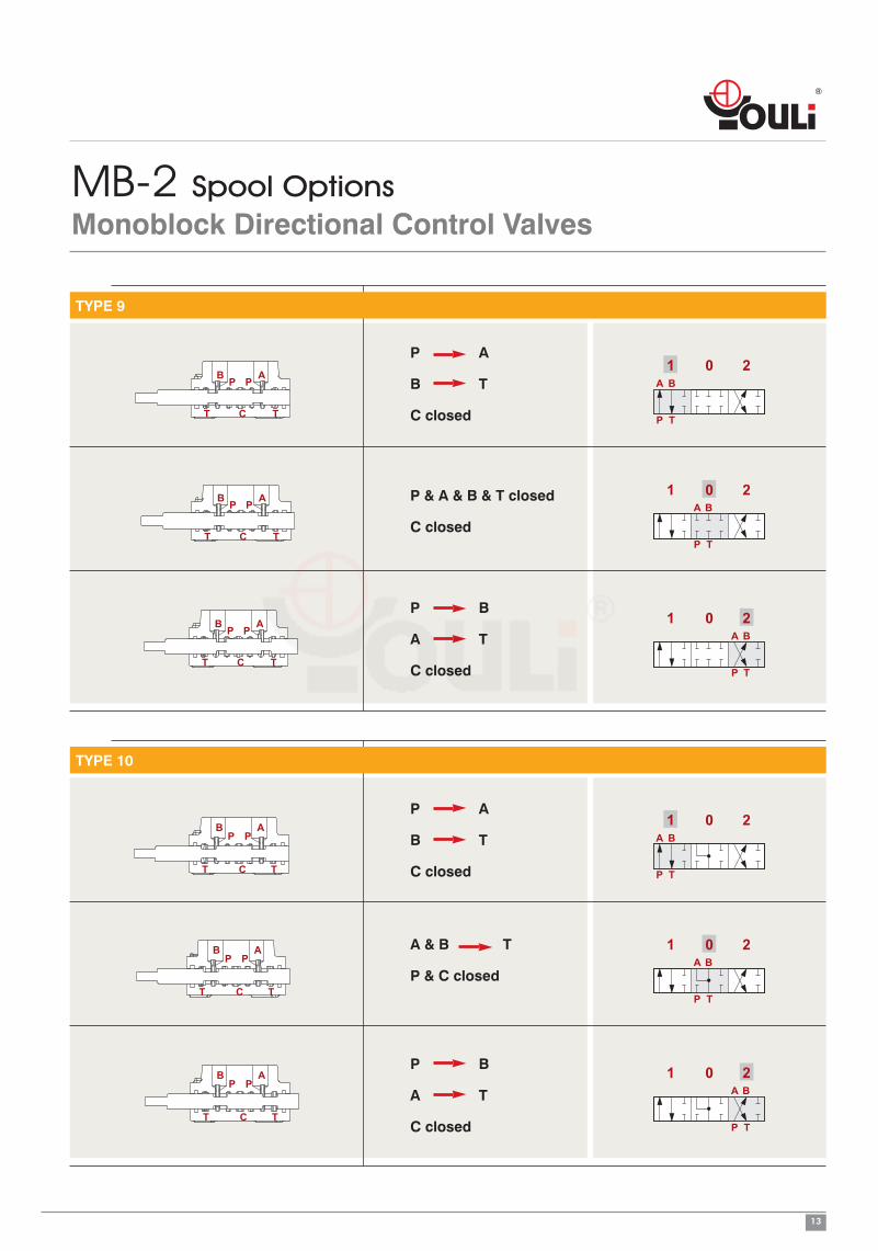
9 YLMB23009 Double acting, 3 positions, with P, T, A, B closed in neutral position (Closed center) P. 13
10 YLMB23010 Double acting, 3 positions, with A, B open to Tank and P, T closed in neutral position (Closed center) P. 13
4: B Side Spool Positioners
TYPE CODE DESCRIPTION PAGE6-1 YLMB24061 Detent in pos. 1-0-2, without spring centered P. 16
6-2 YLMB24062 2 positions, detent in pos. 0-2, without spring centered P. 16
6-3 YLMB24063 2 positions, detent in pos. 1-0, without spring centered P. 16
8D2 YLMB24200 With spring return to neutral position and pin with M8 male thread for dual control P. 16
8EP3 YLMB24300 ON/OFF Electro-Pneumatic actuator P. 17
8P YLMB24080 ON/OFF Pneumatic actuator P. 17
8MG1 (NO) YLMB24801 Microswitch kit operated in pos. 1 (Normally Open) P. 18
8MG2 (NO) YLMB24802 Microswitch kit operated in pos. 2 (Normally Open) P. 18
8MG3 (NO) YLMB24803 Microswitch kit operated in pos. 1&2 (Normally Open) P. 18
MG (NO) YLMB24804 Microswitch with NO terminal P. 18
8MG1 (NC) YLMB248011 Microswitch kit operated in pos. 1 (Normally Closed) P. 18
8MG2(NC) YLMB248021 Microswitch kit operated in pos. 2 (Normally Closed) P. 18
8MG3 (NC) YLMB248031 Microswitch kit operated in pos. 1&2 (Normally Closed) P. 18
MG (NC) YLMB248041 Microswitch with NC terminal P. 18
8 YLMB24008 With spring return to neutral position P. 19
8-1 YLMB24081 2 positions, with spring centered from pos. 1 P. 19
8-2 YLMB24082 2 positions, with spring centered from pos. 2 P. 19
9-1 YLMB24091 Detent in pos. 1, 2 with spring centered P. 19
9-2 YLMB24092 Detent in pos. 2 with spring centered P. 19
9-3 YLMB24093 Detent in pos. 1 with spring centered P. 19
5: A Side (optional)
TYPE CODE DESCRIPTION PAGEL YLMB45000 Standard lever box P. 14
SLP YLMB45001 Without lever box,with dust-proof plate P. 14
TQ YLMB45003 Flexible cable connection P. 15

8
MB-2 DimensionsMonoblock Directional Control Valves
311.22
461.81
923.62
55 2.16
1134.0
01
32
3
0757.2
8201.1
0475.1
02 .2644.2
697 7. 3
6314.1
02. 49146.7
047 5.1
230.90
30
2 x ø8.5
1.18
°51°51
8488.1
85.53.37
200.78
TPA
B
Standard threads
Ports Inlet P A and B Outlet T
BSP G3/8 G3/8 G3/8
UN-UNF 3/4-16 UNF-2B (SAE 8) 3/4-16 UNF-2B (SAE 8) 3/4-16 UNF-2B (SAE 8)
METRIC M18x1.5 M18x1.5 M18x1.5
• G-1/2 : G4 G-3/8 : G3 G-3/4 : G6• SAE 8: E8 SAE 10: E10 SAE 12: E12 SAE 16: E16

9
MB-2 Performance curve chartMonoblock Directional Control Valves
P to T
0
2
4
6
8
10
0 15 30 45 60
Pre
ssu
red
rop
0
50
100
0 5 10 15
(bar) (psi)
(US gpm)
A(B) to P
0
2
4
6
8
10
0 15 30 45 60
Pre
ssu
red
rop
0
50
100
0 5 10 15
(bar) (psi)
(US gpm)
P to A(B)
0
2
4
6
8
10
0 15 30 45 60
Pre
ssu
red
rop
0
50
100
0 5 10 15
(bar) (psi)
(US gpm)
(l/min)
(l/min)
(l/min)
Flow
Flow
Flow

10
MB-2 Inlet Relief (Optional)Monoblock Directional Control Valves
Type DG
ø20.
40.
8Max. 55.7
2.19
Direct pressure relief valve:
Type SV
21 0.83
11.50.45
Relief valve blanking plug:

11
MB-2 Spool OptionsMonoblock Directional Control Valves
TYPE 1
P A
B T
C closed
P & T & A & B closed
C open
P B
A T
C closed
AP P
B
T
AP
B
T
AP
P
PB
TCT
T T
C
C
BA
1 0 2
TP
BA
1 0 2
TP
BA
1 0 2
TP
TYPE 2
P A
B T
C closed
A & B T
C open
P B
A T
C closed
T
B AP
T
P
T T
AB
T
B AP
P
P
P
T
C
C
C
BA
1 0 2
TP
BA
1 0 2
TP
BA
1 0 2
TP

12
MB-2 Spool OptionsMonoblock Directional Control Valves
TYPE 3
P A
C closed
P & A & T closed
C open
A T
C open
B AP
T T
P
C
B AP
T T
P
C
B AP
T T
P
C
1 0 2A
TP
A
TP
A
TP
1 0 2
1 0 2
TYPE 4
B T
P closed
C open
P & B & T closed
C open
P B
C closed
P
AB
TT
P
C
P
AB
TT
P
C
P
AB
TT
P
C
1 0 2B
TP
B
TP
B
TP
1 0 2
1 0 2
"B" port plugged
"B" port plugged
"B" port plugged
"A" port plugged
"A" port plugged
"A" port plugged
13
MB-2 Spool OptionsMonoblock Directional Control Valves
TYPE 9
P A
B T
C closed
P & A & B & T closed
C closed
P B
A T
C closed
ABP
T T
ABP
T T
ABP
P
P
P
T T
C
C
C
1 0 2A B
TP
A B
TP
A B
TP
1 0 2
1 0 2
TYPE 10
P A
B T
C closed
A & B T
P & C closed
P B
A T
C closed
PAB
TT
PAB
TT
P
P
P
PAB
T
C
C
CT
1 0 2A B
TP
1 0 2
1 0 2
A B
TP
A B
TP

14
MB-2 A SideMonoblock Directional Control Valves
22.5
0.89
58 2.28
40 1.57
62.2 2.45
65.5
2.58
20 0.79
1 0 2
Type L
Type L:
STANDART LEVER KIT
58 2.28
38 1.5
45.5
1.79
1 0 2
1 0 2
1 0 2
1 0 2
1 0 2
Type R
Type R:
STANDART LEVER KIT
(ROTATED 180 DEGREE)
40 1.57
48.75 1.92
ø9
21 0.83
90.
35
Type SL
Type SL:
WITHOUT ANY COVER
40 1.57
48.75 1.92
9 0.35
ø9
21 0.83
90.
35
Type SLP
Type SLP:
WITH DUST-PROOF PLATE

15
MB-2 A SideMonoblock Directional Control Valves
Note : CONNECTION KIT NOT INCLUDE CABLE
TQ Kits
Cable
Type TQ
100.39
803.15
903.54
M6 x 1.0 M16 x 1.5
1 0 2
TQ Kit:

16
MB-2 B SideMonoblock Directional Control Valves
Type 8D2
90.
35
22.50.89
371.46
783.07
M8
01 2
1 0 2
8D2 Kit:
WITH SPRING RETURN TO NEUTRAL
POSITION AND PIN WITH M8 MALE
THREAD FOR DUAL CONTROL
Type 6
1 0 2
361.42
1 0 2
0 2
1 0
6-1 Kit:
DETENT IN POS. 1-0-2, WITHOUT
SPRING CENTERED
6-2 Kit:
2 POSITIONS, DETENT IN POS. 0-2,
WITHOUT SPRING CENTERED
6-3 Kit:
2 POSITIONS, DETENT IN POS. 1-0,
WITHOUT SPRING CENTERED

17
MB-2 B SideMonoblock Directional Control Valves
Type 8P
1 0 2
42 1.65
51.52.03
572.24
108.54.27
21 0.83
10.
04
V1
V2
V1 V2
1 0 2
Operating feature :
PILOT PRESSURE (MIN.): 5.5 BAR / 80 PSI
PILOT PRESSURE (MAX.): 10 BAR / 145 PSI
V1 & V2: NPT 1/8 - 27
Type 8EP3
1 0 2
10.
04
51.52.03
1766.93
107.
54.
23 21 0.83
ø40.16
V1V2
1
V1
0 2
V2
Solenoid operating features :
NOMINAL VOLTAGE: 24VDCNOMINAL VOLTAGE TOLERANCE: 10%POWER RATING: 5W

18
MB-2 B SideMonoblock Directional Control Valves
Type 8MG
1 0 2
113
4.45
301.18
361.42
662.6
1 0 2
1 0 2
1 0 2
8MG1 Kit:
MICROSWITCH WITH MALE/FEMALE
CONNECTOR, OPERATED IN POS. 1
8MG2 Kit:
MICROSWITCH WITH MALE/FEMALE
CONNECTOR, OPERATED IN POS. 2
8MG3 Kit:
MICROSWITCH WITH MALE/FEMALE
CONNECTOR, OPERATED IN POS. 1
AND POS. 2
With NO contact (female connector with male end)
With NC contact (male connector with female end)
MICROSWITCHOperating features :
MECHANICAL LITE: • 5X10⁵ OPERATIONS
ELECTRICAL LITE (RESISTIVE LOAD):• 105 OPERATIONS - 7A / 13.5 VDC• 5x10⁴ OPERATIONS - 10A / 12 VDC• 5x10⁴ OPERATIONS - 3A / 28 VDC
24 0.94
471.85
21.5
0.85
40.51.59

19
MB-2 B SideMonoblock Directional Control Valves
Type 8
1 0 2
361.42
1 0 2
1 0
0 2
8 Kit:
SPRING RETURN TO NEUTRAL
POSITION.
8-1 Kit:
SPRING RETURN TO NEUTRAL
POSITION.
(2 POSITIONS)
8-2 Kit:
SPRING RETURN TO NEUTRAL
POSITION.
(2 POSITIONS)
Type 9
1 0 2
58.32.3
1 0 2
1 0 2
1 0 29-1 Kit:
DETENT IN POS. 1, 2 WITH SPRING
CENTERED
9-2 Kit:
DETENT IN POS. 2 WITH SPRING
CENTERED
9-3 Kit:
DETENT IN POS. 1 WITH SPRING
CENTERED

20
MB-2 InletMonoblock Directional Control ValvesA simmetrical body allows the reverse assembly of spool and relative control kit and lever
B
A
P
T
P
T
A B
B
A
P
T
P
T
A B
( Left inlet)
( Right inlet)

21
Memo

22
Memo

23
Memo

24
Memo