company · cathodic protection is an economical method for controlling corrosion on aboveground...
TRANSCRIPT

Company •
• Corrosion and Cathodic Protection Phenomena
·-

• KAR PIRA KAVIR COMPANY
~
I
Corrosion and Cathodic Protection Phenomena
1.1. Corrosion
Corrosion is the gradual destruction of materials (usually metals) by chemical reaction with its
environment.
In the most common use of the word, this means electrochemical oxidation of metals in reaction
with an oxidant such as oxyg;en. Rusting, the formation of iron oxides is a well-known example
of electrochemical corrosion. This type of damage typically produces oxide(s) or salt(s) of the
original metal. Corrosion can also occur in materials other tlhan .metals, such as ceramics or
polymers, althtough in this context,
the term degradation is more common.
Corr-osion degrades
the useful properties of materia Is and
structures inc luding strength,
appearance and permeability
Many structural alloys corrode merely from exposure to mo~sture in air, but the process ·can b·e
strongly affecte·d by exposure to certain substances. Corrosion can be concentrated locally to
form a pit or crack, or it can extend ~cross a wide area more or less uniformly corroding th.e
surface. Because corrosion is a diffusion-controlled process, it occurs on e·xposed surfaces.
As a resutt, methods to reduce the activity of the exposed surface, such as passivation and
chromate conversion, can increase a material's corrosion resistance. However, some
corrosion mechanisms are less visible and less predictable
1.2. Cathodic protection
Cathodic protection (CP) is a technique to control the corrosion of a metal surface by
making that surface the cathode of an el-ectrochemical cell. Cathodic protection systems
are most commonly used to protect steel, water, and fuel pipelines and tanks: steel pier
piles, ships. and offshore oil platforms.
1.2.1. Sacrificial anode protection
For effective C P, the potential of the steel surface is polarized (pushed) more negati ve
until the metal surface has a uniform potential. With a uniform potential, the. dr]ving force
for the conosion reaction is halted.
For galvanic CP systems, the anode
material corrodes under the influence
of the steel, and eventually it must be
replaced. The polarization is caused
by the current flow from the anode to
the cathode, driven by the difference
in electrochemical potential between
the anode and the cathode.
www. kapfkaco .com
,.
..
KAR PIRA KAVIR COMPANY
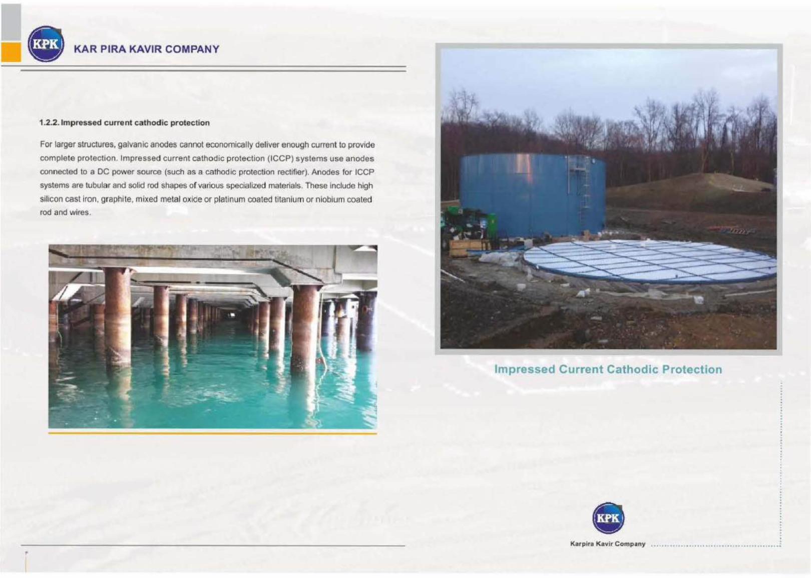
1.2.2. 1mpressed current cathodic protection
For larger structures, galvanic anodes cannot economically deliver enough current to provide
complete protection. Impressed current cathodic protection (ICCP) systems use anodes
connected to a DC power source (such as a cathodic protection rectifier). Anodes for ICCP
sys~ems are tubular and solid rod shapes of various specialized materials. These include high
silicon cast iron, graphite, mixed metal oxide or platinum coated titanium or niobium coated
rod and wires.
Impressed Current Cathodic Protection
Karplra Kavir Company ·~·········· · .-············~·················· · ·'"

• KAR PIRA KAVIR COMPANY
~
I
2.1.Transformer Rectifier
Specification:
The transformer-rectifier will be composed of:
• An input unit.
• A regulating unit of the output voltage.
• Intelligent adjustment with reference electrod.e.
• Output option in constant Voltage, constant current and reference electrode.
• Step-down transformer.
• The measuring instruments.
• Full bridge- full control.
• The electric protection devices.
• Accessories.
All these equipment will be mounted inside a metallic cubicle, suitable for indoor/outdoor
installation.
Working Conditions:
• The oilimmersed transformer-rectifiers will be designed to meet the cathodic p rotection
requirements.
• A.C Supply: 380+10% V three phase 50 Hz, single phase 50 Hz 220 V DC Output: adapted to
requirement
Cooling:
The regulation unit, the step-down transformer and the bridge diodes will be oil-immersed in a
special tank formingthe interior part of the T/Rectifier.
Location: The transformer-rectifiers will be suitable for indoor and outdoor installation, in nonHazardou:s areas.
Cubicle :The transformer-rectifier equipment will contain two parts in a c.ubicle composed of:
• An oil tank where the step-down transformer, the regulating. unit and the bridge rectifier wil l
be located.
• A control unit fixed on the oil tank with all commands, Electrical circuits, measuring instruments, protective devices, fuses and terminals.
The cubicle will be:
• Waterproof and dustproof.
• Designed for mounting on a concrete plinth.
• Fitted with a hinged lockable door.
• Externally painted with two layers of ant irust undercoat and one final layer of pairit suitable
with the specified environment.
Input Unit:
• The trarnsformer-rectifiers will be connected through ON/OFF fuses -switch lockable either in ON or OFF position.
• The power outage and the insulation wil l be conforming to the IEC standard.
Output Regulation Device:
• Output regulation device sha II be provided to allow for a load variation of the output. The variation can be done incontinues method by manual volumes. Manual regulation control shall be easily accessible on control panel.
Bridge Rectifier:
• The bridge rectifier will be of SCR which reverse tension must be of 1200 V as mirnimum.
Measuring Instruments:
• The measuring instruments will be having built- in type, different dimensions.
• The range of measuring instruments will be such that the maximum working value is indicated at 70% of fu ll scale deflection.
• The ammeter will mounted in parallel to a calibrated to a suitable shunt.
• The voltmeter will be protected withsuitable fuses.
• A red line will indicate the maximum output value. The measuring instruments will be located inside thecontrol part of T/R cubicle in front face.
Electrical Protection Devices:
• Against Over Voltages
Resistance capacitor circuit will be connected in parallel to the bridge rectifier. An arrester will be connected between thie plus and minus poles of the TJRectifier.
• Against Over intensities
Ultra-fast fuses suitably dimensioned in 12.t will protect the A.C. and D.C. circuits.
• Personnel Safety
PVC caps will avoid direct contact with the different poles and instruments.
• Earthing
All metallic parts will be electrically continuous and one earthing terminal will allow their cGnnection to an externalcircuit.
• Accessories:
The transformer- rectifiers wi ll be supplied complete with all necessary accessories for installation, control and operation.
• Oil control
The oil tank part will be fitted with a dial thermometer calibrated. in degree centigrade and located in a pocket at thenormal oil level. The oil level inside the tank will be controlled tanks to a sight glass gauge externally locateq in thefront of the cubicle whic.h will be protected against the shocks py a hinged flipper marked "LEVEL"
www. kap f ka co .com
v
I
• KAR PIRA KAVIR COMPANY
" I
Fittings
For handling, two lifting rings will be foreseen at the top of the cubicle.To maintain a dry
atmosphere in the T/Rectifier, an external and removable silicagel cartridgewill be mounted on the
tank inside the control part. For incoming and outgoing cables, weatherproofpacking glands wil! be
foreseen j ust in front of the terminals on the control part.
Time Switch:
This equipment is intended to measure interferences between two pi:pelines catholically protected
or not and coatingresistance value of the pipeline.The time switch Will be composed of:
Two adjustable time relays. a selector switch connected to the mains supply. The time switch will
enable a continuouscycle of 2 minutes ON and 3 minutes OFF. It wiU be dimensioned according to
the T/R characteristics.
Factory Tests:
The transformer - rectifiers will be tested according to the IEC standards tests method. The
following routine testisshall be carried out on each unit.
Measurement of inherent regulation.
Insulation test.
Power loss measurement.
Power faction measurement.
Temperat1,1re rise test.
Load test at different steps.
Ratio and polarity test.
For type tests, factory test report may be
acceptable.
Ultra-fast fuses suitably dimensioned in
12.t will protect the A.C.and D.C. circuits.
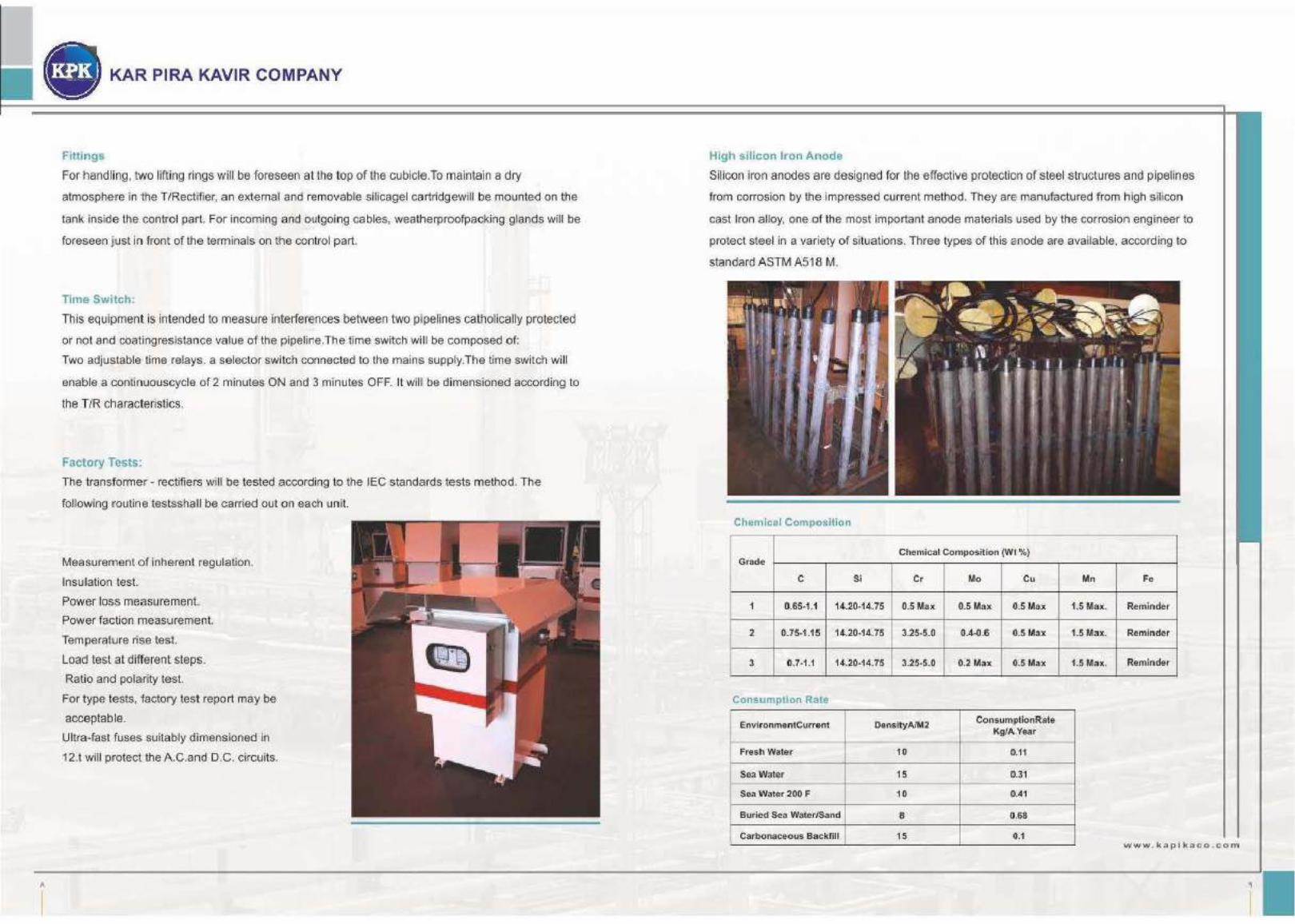
High silicon Iron Anode
Silicon iron anodes are designed for the effective protection of steel structures and pipelines
from corrosion by the impressed current method. They are manufactured from lhigh si licon
cast Iron alloy, one of the most important anode materials used by the corrosion engnneer to
protect steel in a variety of situations. Three types of this anode are available, according to
standard ASTM A518 M.
Chemical Composition
Chemical Composit ion (WI%) Grade
c Si Cr Mo Cu Mn Fe
1 0.65-1.1 14.20-14.75 0.5 Max 0.5 Max 10.5 Ma.x 1.5 Max. Reminder
2 0.75-1.15 14.20-14.75 3.25-5.0 0.4·0.6 0.5 Max 1.5 Max. Remin der
3 0.7-1.1 14.20-14.75 3.25-5.0 0.2 Max 0.5 Max 1.5 Max. Reminder
Consumption Rate
EnvironmentCurre nt DensityAIM2 Consumption Rate Kg/A. Year
Fres.h Water 10 IU1
Sea Water 15 0.31
Sea Water 200 F 10 G.41
Buried Sea Water/Sand 8 0.68
Carbonaceo us Backfill 15 ().1 ww w . kapfk aco . co m
~
I

• KAR PIRA KAVIR COMPANY
I•
I
• Physical Property of Silicon Iron
Properties Unit Re quire ment Test Method (ASTM)
Density glcm3 7-7.05 Approved Method
Hardness (Min) HB 500 E 10
Compressive Sirength (Min) Mpa 650 A256
Electrical Resistivity (Max) ..,rl.cm 72 B 193
Impact Resistance (Min) J 0.1 A 327 (Charpy Type)
Silicon Iron anodes are cast in several shapes and size to meet a variety of requirements.
The following table shows details of the lfange available.
• Size of Anode:
Rod Type
Diameter (mm) Head Diameter(mm) Lengh (mmJ Net Weight (kg)
51 76 915 14.5
51 76 1220 19
51 76 1525 22.5
76 102 915 29
76 102 1220 38
76 102 1525 49
• Tubular Type
Inside Oiameter(mm) Outside Diameter(mm) Thickness Lengtlil Net Weight (mm) (mm) (kg)
67 47 10 1067 14
56 ~6 10 2134 21
67 47 10 2134 29
95 75 10 2134 39
121 100 10 2134 50
121 86 17 2134 79
• Anode Cap
Anode caiPS may be factory fitted to cabled anodes. They are designed to counteract, and
effect, when single end anode connections are specified. The caps have protective
polymeric lining capable of withstanding corrosive environmental conditions including
chlorine and Sulphate attack.
They are manufactured from cross-linked polyethylerne and shrink fitted over the anode. The dielectric strength of the end caps is 10 kV per mm.
2.1 Mixed Metal Oxide (MMO)Anode
Mixed Metal Oxide Ribbon Anodes (Protection For Above Ground Tank Bottoms)
Cathodic protection is an economical method for controlling corrosion on aboveground stora·ge tank bottoms. While sacrificial systems can be used, impressed current designs have proven to be more cost effective and easier to install. The anodes are composed of a titanium ribbon substrate coated with a mixed metal oxide catalyst. Because the titanium Sl.!lbstrate. is naturally passivized by :an oxidizing film, the ribbon anode remains dimensionally stable over time. Direct current transfer is accomplished through the mixed metal oxide catalyst which is highly conductive, and fully oxidized so that higher current outputs are possible.
This two part composition allows for a
maximum current density of S.OmA/ft to
achireve a 50- 100 year design life. Spacing
between the metal anode strips can be
adjusted to achieve var'ious design life
requirements. The anodes can also be easily
cut so that placement may be made under all
areas of the tank. Because the strips are
electrically continuous, multiple paths ar.e
avairlable for current flow. This in turn lowers
the driving voltage required for protection, and
provides the anode with redundant electrical
connections for increaseq reliability. Greater
dependability is also achieved throug,h the
elim ination of fie ld splices.
www. kapfk aco .com
II
I

• KAR PIRA KAVIR COMPANY
Mixed metal oxide rilbbon anodes are designed for use on both newly constructed aboveground storage tanks with
secondary containment liners, and existing tanks utilizing
double bottom construction. Unlike other umpressed current tank bottom anodes, ribbon anodes do not require
coke breeze. Tlhey can be used in sand with various levels
of moisture and salt content, and can be designed to provide effective protection for 50 years or more.
Chemical Composition
Substrate
AST.M B-265 Grade 1 Titanium
Catalyst
Nominal Dir:llensi6ris
Component Width Thickness
Inch mm Inch
Anode Ribbon 0.25 6.4 0.025
Anode Ribbon J.5 12.7 0.025
Conductor Bar 0.5 12.7 0.40
Mixed Meta I Oxide Tubular Anodes (Dimensionally Stable in All Environments)
mm
0.6
0.6
1.0
To obtain the highest level of protection from an impressed currentcatlilodic protection system, you need
an anode with a ve.ry low consumption rate and high current capacity. With tUbular mixed metal oxide line
of anodes, you get powerful protection.and unsurpassed stability. The anodes are made using tubular titanium substrates which are coated with a mixed metal oxide catalyst.
The catalyst is thermally applied to the titanium to form an extremely chemical resistant bond. This
special composition brings together the stability of titanium with the consuctive properties of the mixed
metal oxide catalyst to achieve supe_rior performance. In soil and fresh water applicattions, the anodes
have a recommended c;urrent density approximately 100Amp/m:!, and can be operated over 500Amp/
m2in sea water environments. Even at these relatively high drscharge levels, the anodes will be
consumed at less than 1.0 mg/A.year.
The tubular design of these anodes also
allows for numerousperformance benefits.
The tubular configuration provides a larger
surface area which in turn permits greater
current output and lower anodetoearthe
resistance.
The tubular style also means lead wire
connections can be made in the center of
the anode . With tupular anodes, th is
connection consists of a brass wedge
connector which grips firmly to the internal
circumference ofthe anode.
This connectio·n is protected from moisture
intrusion by a waterproofing sealant which
fills the entire anode tube. One end of the
anode is then covered with shrink tubing
for a comp letely sealed electrical
connection. Anodes are then tested for
quality assura111ce.
Standard Dimension and Shipping Weughts
Nominal Dimension Nominal Weight
Anode Type Diameter Length Bare Packaged
Inch mm Inch mm oz/ft g/m lbs kg
KPKG1 0.75 10.1 2.0 610 3.4 314 23 2.6
KPK02 0.75 19.1 4.0 1219 3.4 317 25 18 .. f
KPK 03 1.0 25.4 3.3 1000 3.8 351 25 11.4
KPK04 1.25 31 .8 4.0 1219 3.8 538 27 12.3
Based on 20 year design life in calcined petroleum grade <coke
Current Rating*
Am per
10.5
16.9
www. kapfk a c o . com
II"
I

II'
I
KAR PIRA KAVIR COMPANY
Coke Breeze.2.1
Coke breeze is used for backfill in vertical, horizontal and well ground bed.
Advantages of backfill are:
Preventing from direct contact anode with soil (a
Increase anode dimen sion to decrease anode resistance (b
Decreasing resistively around anode (c
Providing uniform envirohmenl around anode {d
Physical Property of Silicon Iron
Properties of coke Type 1
Carbon Content (%Min.) 80
Moisture Content (%Max.) 5
Ash Content (%Max.) 15
Sulphur Content (%Max.} 1
Volatiles Content (%Max.) 5
Type 2
90
5
5
5
5
TypeS.
95
1
3
1
1
Density (l(g/m') 65<J.a00 700-1100 1050-1200
Type1 Less than 10mm 100%
Greater than 1 mm 90%
Typo 2 Loss thon 3 mm 100%
Greater lhar'i 0.5 mm 90%
Type 3 Less than 1.0 mm 100%
Less than 0.6 mm 80%
Greater than 0.4 mm 90%
Greater than 0. ' 5 99%
mm
Sacrificial Anode Cathodic Protection
Karp ira Kavir Company .................. , ...•....•........•.

• KAR PIRA KAVIR COMPANY
If
I
-. SBJ.. .cJ It' at ¥'l'l!!l h.1t , . ode
Magnesium anodes are used seldom in cathod rc protection with more than 10 years life design.
These anodes are not used in soils with high resistivity because drain of necessary current density
needs large amount of magnesium and it is not economic.
These are used wher:~ necessary current is low, soil
has low resistivity, and or when input current source
for transformer rectifier is not available.
Magnesium anodes have an advantage and it is
better and simpler current distribution than
impressed current system due to current drain in
small field .
There is over protection near drain point that is
causes current lose. Consequently, Current lose
can be minimized by proper control
Cflemk:al <:omposftlof\ (Aec~Jf&ng to ASTM 8 MS)
ELEMENT
AI
zn Cu
Sl
Fe
Mra
Pb
Mg
Other impurities, each
Total other impurities
Capacity = 1230 Ahr/kg
WEIGHT PERCENT
5.326.75
2.5·3.5
0.08 Max
0·.3 Max
0.005 Max
0.25 Max
0,03 Max
Reminder
--
--
Anodes used in land shall be backfilled to reduce resistance a111d moisture absorption.
Specifications of anode backfill are as fol low:
Powdered Gypsum: 75%
Granular Bentonite: 20%
Sodium Sulphate: 5%
Also cables for anode connection shall be made from copper and XLPE or PVC insulation coat.
.,. 2 s -:rfflel r k.; i • '"' AO.d ..
Aluminum anodes are one type of sacrificial anodes in cathodic protection systems tlhat are
used generally in offshore industries for metals corrosion protection.
CHlHU:t.. CO PC. ITION
The chemical composition of anodes. is as follow according to DNV RP 8401 standard:
Element Weight Percent
FEt 0.09 max
Sl 0.12 max
Cu 0.003max
2n 2.5-5.0
hi 0.015~.040
Others 0.02 max
AI Remainder
.. LECT-.Oi'HE lr"L JEHAVIOR
According to DNV RP 8 401 standard, the electrochemical properties of aluminum anode
shall be as follow:
Minimum Electrochemical Efficiency: 2500 Ahr/kg. ·
Minimum Open circuit potential: -1.05 V respect to Ag/AgCI Reference Electrode.·
Minimum closed circuit potential: -0.8 V respect to Ag/AgCI Reference Electrode. ·
www. k apfk aco .com
IV
I
lA
KAR PIRA KAVIR COMPANY
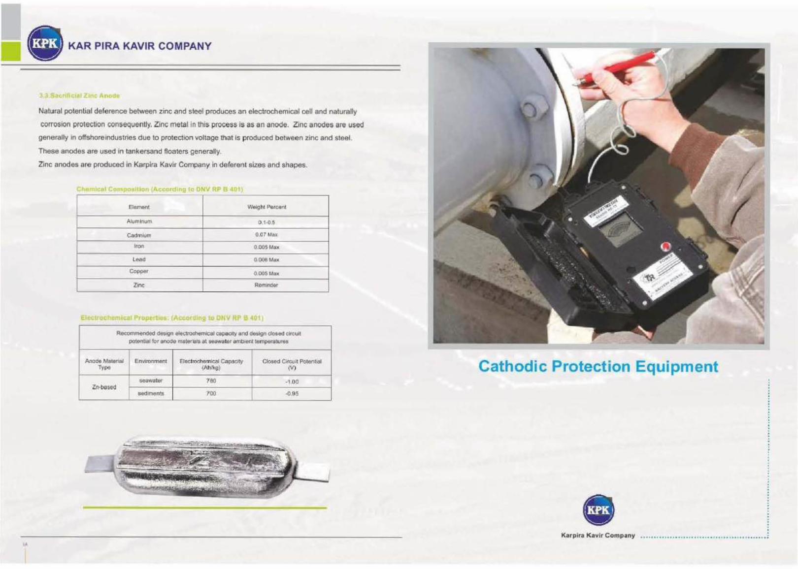
Natural potential deference between zinc and steel produces an electrochemical cell and naturally
corrosion protection consequently. Zinc metal in this process is as an anode. Zinc anodes are used
generally in offshore industries due to protection voltage that is produced between zinc and steel.
These anodes are used in tank-ersand floaters generally.
Zinc anodes are produced in Karpira Kavir Company in deferent sizes and shapes.
I mlca4 Compo!Jtti~n (Accordtng f4 J l I P 401)
Element Weight Parcenl
Aluminum [).1-0.5
Cadmium 0.07 Max
Iron 0.005 Max
Lead 0.006 Max
Copper 0.005 Max
Zinc Remtnder
E 11
RecomiTlilnded design electrochemical capacity and design dosed en-cult
potential for anode ma!erials at seawater ambient temperatures
Anode Material Environment Electrochemical Capacity Closed Cirou it Potential Ty!Pe (Ah/kg} (V)
·seawa!er 780 ·1.00 Zn·based
sediments 700 -0.95
Cathodic Protection Equipment
Karplra K avir Company

• KAR PIRA KAVIR COMPANY
4.1. Pos[tive and Negative Bond Boxes
The standard bond box is designed for basic cable connections that do not require shunts or resistors,
and contains ol!lly terminallugs. They are provided in various sizes to accommodate numer.ous types
of wires. The non-conductive panels are resistant towarpage and weathering. Positive and negative
bond boxesshall be as per standard and meet the requirements of climatic conditions. The boxshall be
made of 3 mm thickness sheet steels and tine degree of protection shall beiP-55.After assembly of test
box to mounting pipe & prior to installation, all steel partsshall be painted with! following procedure:
a) Surface preparation to sa21/2.
b) One red lead primer(70microns).
c) One intermediate coat ofalk.yd paint (1 00 microns at least)
d) One finishing coat of alkyd glossy yellow color paint (1 00 microns)
(Total thickness of painting 270 microns at least)
4.2. Cathodic Protection Cables
CONDUCTOR
The conductors shall be plain annealed stranded copper. St randing shall be circular{noncompacted).
The material shall be copper of such quality and purity that the finished product shall have the
properties and characteristics prescribed in IEC Publication 228 Class 2, or ASTM specification 88
Class B. Conductor sizes, as wi ll be specified by the Purchaser, shall be in accordance with one of the
designations listed in Table 1 to achieve the resistance value required:
TABLE 1 - Phys ical Properties ofXLPEJPVC Cables
Nominal Cross Nominal Insulation Nominal Sheath Approx. Overall Approx. Weight Maximum Rasistance Of
Section Thickness Thickness Diameter (mm) Cond uctorat 2o•c
4mm• 0.7 mm 1.4 mm 6.8mm 77 kg/km 4.52 Q/Km
6mm' 0.7 mm 1.4mm 7.4 mm 100 kg/km 3.020/Km
1·0 mm• 0.7 mm 1.4 mm 8.3mm 144 kg/km 1.79 0 /Km
16 mm• 0.7mm 1.4 mm 9.3mm 207 kglkm 1.13 0/Km
25mm• 0.9 mm 1.4 mm 11.0mm 305 kg/km 0.712 0/Km
3smm• Q.9mm 1.4mm 12.2 mm 406 kg/krn 0,514 0/Km
50' mm• 1.0 mm 1.5mm 14 mm 560 kglkm 0.379 0 /Km
70mm• 1.1 mm 1.6mm 16 mm 770 kglkm 0.262 0 /Km
95mm• 1.1 mm 1.6 mm 18 mm 101 5 kglkm 0.19 0/Km
The size, cross-sectional areas, and direct
current resistance of the conductor in the
completed cable is conformed the minimum and
max imum val ues allowed by the above
referenced standards.
Single Core Plain annealed copper conductor,
XLPIE insulated I PVC extruded bedded I steel
wire armoured I PVC sheathed. 600 I "1 000 volts
grade to BS5467.
TABLE 2 - Physical Properties of XLPE I PVC I SWA I PVC Cables
Nominal Cross-Sectional Number of Strands Approximate
Area Overall Diameter
16 7 13.5
25 7 15.3
35 7 17.4
50 7 19.1
70 19 21 .1
95 19 23.4
120 19 26.3
INSULATION
Approximate Weight (Kg/1'\m)
435
575
805
1010
1210
1620
2100
Cable insulation shall be mad·e from ma~erials chemically and physically resistant to the environmental effects to be anticipate.d in buried or submerged service. It shall provide
continuous coverage, adequate dielectric properties, and have a high resistance to abrasion, stress cracking and notch propagation. The insulation shall be one of the types
listed asbelow. The insulation shall be applied t ightly to the conductor without adhering to it
and shall form a compact and homogeneous body.
The sheath Gacketing) shall be an extruded layer of the types listed as bel.ow. The sheath
shall be continuous having a thickness as uniform as possible and not less tharn the values
specified . It shall be possible to re-move the sheath of the cable without damaging the
insulation of the conductor. Cable insulation (primary insulation and sheath) shall be completely free of cracks, nicks, scratches, or other discontinuities. Cable insulation shall
have a voltage rating of 60011000 Volts in accordance with National Electrical Code.
The types of insulation ahd sheath compo1und c-overed by this Part of Standard SIPecification
are listed below.
www.kapl ka co .com
r1
I

• KAR PIRA KAVIR COMPANY
r~
I
Polyvinytchloride (PVC)
Insulation and ~heafih compound based on polyvinylchloride or copolymer of vinyl chloride and vinyl
acetate conforming toASTM specifications 0 2219 (as Insulation) and 0 1'047 (as Jacketing).
High mol~cular weight polyethylene (HMWPE}
Insulation and sheat!h compound based on thermoplastic polyethylene conforming to ASTM
specifications D 1351 (as Insulation) and D 2308 (as Jacketing).The polyethylene before application
to the conductor (or cable) shall comply with the requirements of ASTM specification D 1248 for
type I, Class A. 8 , or C; category 5; grade E5 otr J3.
Cross-Linked polyethylene (XLPE)
Insulation compound based on chemically cross-linked polyethylene conforming to ASTM
specification 0 2655. The base polymer of this insulation consists substantially of polyethylene or a
polyethylene copolymer.
PolyvinyUdene fluoride (PVDF)
Insulation compound based on especially chemical-resistant modified polyvinylidene fluoride
conforming to ASTM specification 0 3144.
Thermit Welding
The complete Thermit welding (Cadweld) kit includes cadweld powder and other accessories like
cadweld mould,ignition gun and ...
Cadweld Powder
This part specification covers the minimum requirements for the supplyof Thermit weld(cadweld)
powder for connection of cathodic protection leads to new or in-servicesteel pipes by Thermit welding
process. The Thermit weld powder for all welds of coppercable to steel pipe irrespective of c.able size us
variable due to the cable s9ze. Each cartridgepowder charge shall be enclosed in a separate
polyethylene tube with ignition powder atthe bottom or separate. The ignition powder has special
degree for ignition.The materiaJshall be of such quality and purity that when applied , produces strong
and permanent higihconductivity connection. The material shall meet the initial properties after storage
forat least 3 years from the date of delivery at normal storage conditions.
Cadweld mould
Cadweld mould is in two types of horizontal and vertical connections of cable to the pipe. The
size of mould depends on the size of cable which wil l be connected.
Ignition Gun
To ignition the powder for beginning of the welding process the operator uses an ignition g:un.
The packing material ofthe welding cartridge will prevent the ingress of moisture. The size of
welding cartridge fits into the holder to be used.
Overall: 4" X 4''
0 P-lastic sheet: 2.75" x 4" {serrated) ~r (b :J II> c;·
Sheet lllfckness: 10 mHs
iil Plastic dome: 1.625" dia, 0.8" height
Adhesive lllickness: 165 mils
Weight 2.1 oz
Application temperature -20 to +120°F
Service temperature -40 to + 1as·F
Shelf life Rollate imn uany
www. kapfk aco . com
T
• KAR PIRA KAVIR COMPANY
Yl'
I
Portable Copper/Copper Sulfate Reference Electrodes
Reference electrodes provide accurate and reliable potential measurements on buried metallic
structures. Theirplacement in close proximity to protected structures permits readings which are more
exact andlless affected byfluctuating soil conditions than those obtained by portable cells. Long-fife
performance is achieved through a ruggeddesign, which includes impact resistant PVC tubing. The
tubing houses .a 99.99% pure copper element .and a supersaturatedsolution of copper su lfate. The
copper sulfate mixture ensures that the copper element remains electricallystable, so that the cell's
potential value will not fluctuate. From this special composition, the cell achieves a minimumdesign life
of fifteen years, and maintains an accuracy level of±5 mill ivolts.
PermanentCo pper!Copper Sulfate Refe renee Electrodes
The cell is pre-packaged in a cfo.th bag containing a low-resistance backfill material, an·d is completely
assembled and ready for immediate installation.
Plastic positioning pins on the cell assure that a sufficient amount of the backfill will exist around the
cell's electrical contact point. Because of this, a low-resistance ground bed can be created simply by
watering the area surrounding the cell. Lead wire connections to the cell are made, wire containing any
designed cable insulation (mostly 1 Osqmm PVC insulated). The length of the wire is depending o·f the
location of cell installation.
Reference electrodes are normally used for measuring structure/electrolyte potentials, or as sensing
electrodes for control system.
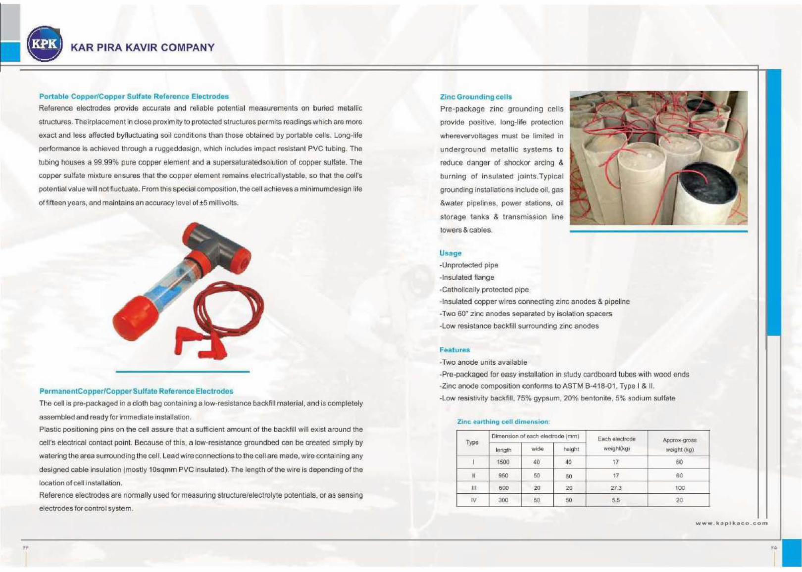
Zinc Grounding cells
Pre-package zinc ground ing cells
provide positive, long-life protection
wherevervoltages must be limited nn
underground meta llic systems to
reduce danger of shocker arcing &
burning of insulated joints.Typical
grounding installations include oil, gas
&water pipelines, power stations, oil
stor.age tanks & transmission line
towers & cables.
Usage
-Unprotected pipe
-Insulated flange
-Catholically protected pipe
-Insulated copper wires connecting zinc anodes & pipeline
-Two 60" zinc anodes separated by isolation spacers
-Low resistance backfill smrounding zinc anodes
Feat ures
-Two anode units available
-Pre-packaged for easy installation in study cardboard tubes with wood ends
-Zinc anode composition confo1rms to ASTM B-418-01 , Type I & II.
-Low resistivity backfill, 75% gypsum, 20% bentonite, 5% sodium sulfate
Zinc earthing cell dimension.
Type Dimension of each >electrode (inm)
EacA electrode Approx-gross
length wide height weight(kg) weight (kg)
I 1500 40 40 17 60
II 950 50 50 17 6•0
Ill 600 20 20 27.3 100
IV 300 50 50 5.5 2•0
www. kapl kaco .com