micrometldms.hvacpartners.com/docs/1009/public/0c/iik582a1813.pdf · down discharge 2 ill.5...
TRANSCRIPT

INSTALLATION INSTRUCTIONSfor 0637-0111 Economizer (CPECOMZR003A00)
063748GS1842ECMicroMetl
M M C 3035 N. Shadeland Ave., Suite 300 Indianapolis, IN 46226 MMC West 202 South 18th St. Sparks, NV 89431
Manufacturer reserves the right to discontinue, or change at any time, specifications, designs and prices without notice and without incurring obligations. Form No. IIK 582A-18-13 / 48/50-104SI Catalog No.534-80092 Copyright MicroMetl Corporation 2001. All rights reserved.
MicroMetl's 0637 economizer is convertible-it will working in either a down discharge or horizontaldischarge application. Read these instructions completely and carefully before beginning installation.
1. Remove the side panel from the HVAC unit, ILL 1.Discard panel.
2. The bottom filter rack is built into the economizerwhile the top rack is installed separately.
3. On the top rack, bend the divider flange at 90o at thenotched corners, ILL. 2.
4. Raise the rack to the top of the coil and all the way tothe left side of the unit. Line up the prepunched hole infilter rack with the prepunched holes in coil's frame.Install (1) ½" long screw. (ILL. 3 & 4)
For Down Discharge(for Horizontal Application go to page 4)
htdiWretliF eziS/.ytQ
retlif"1 "1X"02X"21)2(
retlif"2"2X"02X"01)1("2X"02X"21)1(
Rack DetailILL. 3
Screw
Coil
Bend this flange at 90o
screw to divider with 1"screw
Top filter rack
EvaporatorCoil
Rack DetailILL. 4
Filter retainerclips
Prepunchedholes
ILL. 2
1 7/8"
22"
Side Panel shippedwith HVAC unit.Remove and discard
ILL. 1
Bend this flangeout at 90o
CompressorCompartment
DownDischarge
2
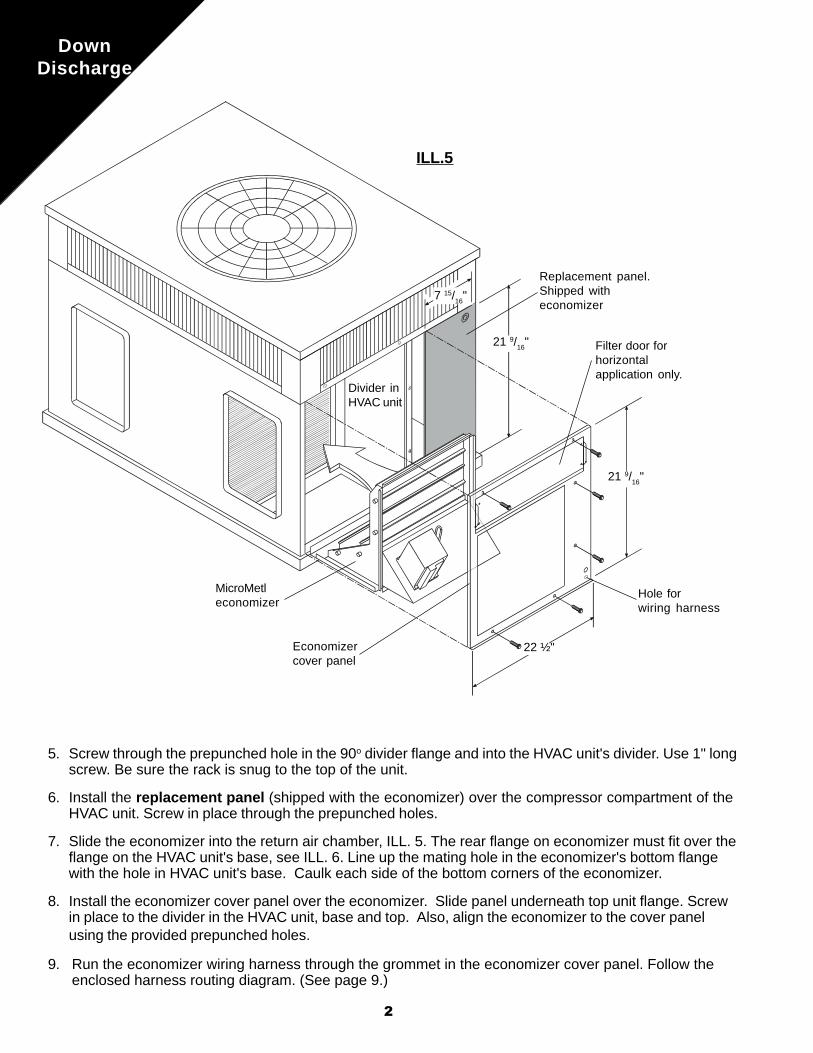
ILL.5
Replacement panel.Shipped witheconomizer
MicroMetleconomizer
Divider inHVAC unit
Filter door forhorizontalapplication only.
5. Screw through the prepunched hole in the 90o divider flange and into the HVAC unit's divider. Use 1" longscrew. Be sure the rack is snug to the top of the unit.
6. Install the replacement panel (shipped with the economizer) over the compressor compartment of theHVAC unit. Screw in place through the prepunched holes.
7. Slide the economizer into the return air chamber, ILL. 5. The rear flange on economizer must fit over theflange on the HVAC unit's base, see ILL. 6. Line up the mating hole in the economizer's bottom flangewith the hole in HVAC unit's base. Caulk each side of the bottom corners of the economizer.
8. Install the economizer cover panel over the economizer. Slide panel underneath top unit flange. Screwin place to the divider in the HVAC unit, base and top. Also, align the economizer to the cover panelusing the provided prepunched holes.
9. Run the economizer wiring harness through the grommet in the economizer cover panel. Follow theenclosed harness routing diagram. (See page 9.)
22 ½"
21 9/16"
21 9/16"
7 15/16"
Economizercover panel
Hole forwiring harness

DownDischarge
3
Coil
Economizer
ILL. 6
ILL. 7
TOP VIEW ILL. 8
Filter access door - Forhorizontal applicationonly. Do not remove fordown discharge.
Replacementpanel
Hole for economizerwiring harness
Rainhood
Filter accessdoor - hinged
10. Caulk the mating flanges of the rainhood andscrew to the economizer panel throughprepunched holes. The top flange of hood goesbehind the horizontal access door. (After adjust-ing the minimum position setting on the actuator,install the 21 3/16" x 17 1/8" aluminum filter in therain hood.)
11. Remove the cover panel shipped over thehorizontal return opening. Locate the filteraccess panel and gasket mating flanges. Screwthe hinge to the HVAC unit over the horizontalreturn opening. Adjust the closure handles for atight seal.
12. Install the provided filter access sticker on thehinged door.
13. Be sure the seams are all water tight. Seal asrequired.
14. Follow the wiring instructions enclosed.(see page 8)
Filter
Compressor
Economizer
ReplacementPanel
EconomizerHood
0"
CoilFilter
Hinge
16 ¼"
1 1/8"
19 5/8"
This filter rack will notbe used in the downdischarge application.
ILL. 9
Door latchangle
Install filteraccess doorsticker
AluminumFilter
Horizontal supplyair cover panel.Shipped on HVACunit.
Caulk bottomcornersof economizereach side
18 "
HorizontalDischarge
4
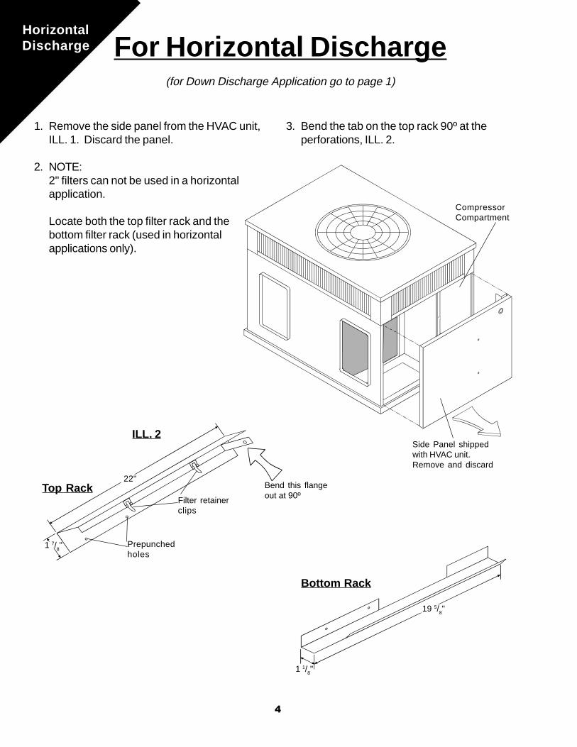
For Horizontal Discharge(for Down Discharge Application go to page 1)
1. Remove the side panel from the HVAC unit,ILL. 1. Discard the panel.
2. NOTE:2" filters can not be used in a horizontalapplication.
Locate both the top filter rack and thebottom filter rack (used in horizontalapplications only).
Side Panel shippedwith HVAC unit.Remove and discard
Filter retainerclips
Prepunchedholes
ILL. 2
1 7/8"
22"
19 5/8"
1 1/8"
Top Rack
Bottom Rack
Bend this flangeout at 90º
3. Bend the tab on the top rack 90º at theperforations, ILL. 2.
CompressorCompartment

HorizontalDischarge
5
4. Install the bottom rack. Slide the rack to the farleft side (when facing the coil) of the HVACunit. Set the rack in front of the coil and screwthe rack to the coil frame through theprepunched holes. Maximum screwlength - ½" .
5. Install the top rack with the tab bent at 90o atthe perforations. Raise the rack to the top ofthe coil and slide to the far left. Screw the rackto the coil frame through the prepunchedholes. Maximum screw length ½". Screwthrough the 90° bent flange and into unit'sdivider. Use 1" long screw.
Rack InstallationILL. 3
ILL. 5
Filter PlacementILL. 4
Bend flange at90º Screw todivider with 1"screw
Top filter rack
Bottom filter rack
EvaporatorCoil
Coil
Screw
Screw
Top Rack
BottomRack
Coil
Filter
Top Rack
BottomRack

HorizontalDischarge
6
6. Install the replacement panel over the compressor compartment. Screw in place through theprepunched holes.
7. Install the 5/8" gasketing on the bottom flanges of the economizer, ILL. 6.
8. Turn the economizer on its side as shown, ILL. 6. Slide the economizer into the cabinet and as farto the left as possible. The economizer will set against the left side of the HVAC unit. Caulk asrequired.
9. Screw through the bottom flange and through the economizer rear flange into the unit side.
10. Install the economizer cover panel over the opening and economizer. Panel slides underneath topflange of unit.
NOTE:The relief damper must be sealed shut for the horizontal discharge application.
Replacement panelShipped with economizer
Divider inHVAC unit
Screwinto base
Gasketing,3 Sides.
Economizercover panel
Screw
21 9/16"
7 15/16"
21 9/16"
22 ½"
ILL. 6
Screw thru prepunchedhole on economizerrear flange into theunit side Caulk these corners
after economizer isinstalled
HorizontalDischarge
7
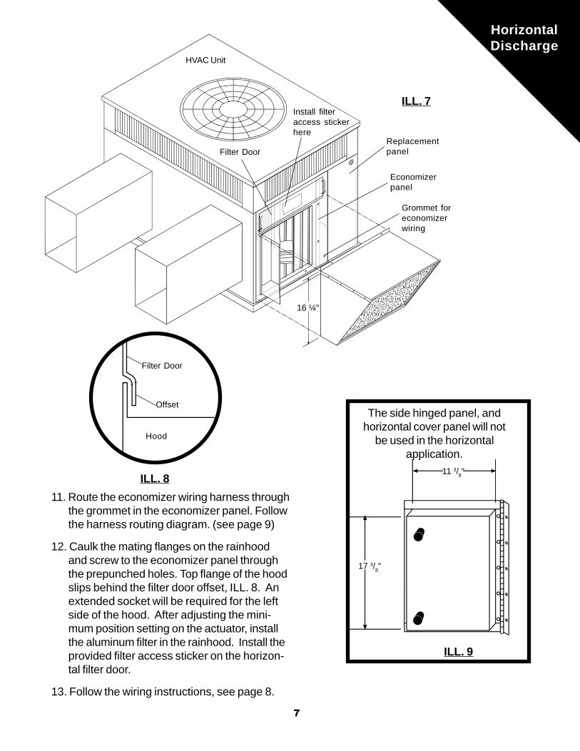
Install filteraccess stickerhere
11. Route the economizer wiring harness throughthe grommet in the economizer panel. Followthe harness routing diagram. (see page 9)
12. Caulk the mating flanges on the rainhoodand screw to the economizer panel throughthe prepunched holes. Top flange of the hoodslips behind the filter door offset, ILL. 8. Anextended socket will be required for the leftside of the hood. After adjusting the mini-mum position setting on the actuator, installthe aluminum filter in the rainhood. Install theprovided filter access sticker on the horizon-tal filter door.
13. Follow the wiring instructions, see page 8.
ILL. 9
ILL. 8
ILL. 7
Filter Door
Offset
Hood
Economizerpanel
Filter Door
HVAC Unit
Replacementpanel
Grommet foreconomizerwiring
16 ¼"
11 3/8"
17 3/8"
The side hinged panel, andhorizontal cover panel will not
be used in the horizontalapplication.

8
Orange
Green
Wiring Diagram for 0637 Series Economizers (not Heat Pump) - CPECOMZR003A00 & CPECOMZR004A00
2- STAGETHERMOSTAT
R G Y1 Y2W1
23
Grn.
Brn
.
Yel.
Red
Blu
e
TR
SR
SO
TR1
+
+
P
3
1
T
4
5
2
P1
T1
P
P1
T1
T
TR1
TR24 VAC
resistor8
Discharge Sensor Gray
EconomizerACTUATOR
Gray
4
+s
2K
1K
1S
1S1
67
5
Min.Pos
1NOTES:
EquipmentTransformer
Main 24VSplice Box
Optional RemotePotentiometer
Dry Bulboutside airsensor(or optionalenthalpy)
Form No. IIK 582A-18-13
2
3
4
5
6
7
8
WIRING LEGEND
Terminals
Wire nut of equivalent connection
MMC wiring harness
Field supplied low voltage wire
Field supplied high voltage wire
Other low voltage wireL
1. Disconnect power supply beforeconnecting writing to preventelectrical shock or equipment damage
CAUTION
L2L1 Yellow
Green
Brown
White
Red
Min
imum
Pos
ition
Dis
char
geS
en
sor
OPTIONAL LOW AMBIENT CONTROL
TRANSFORMER IN HVAC UNIT.
POWER SUPPLY. DISCONNECT MEANS AND OVERLOADPROTECTION AS REQUIRED.
MUST BE INSTALLED ON SUPPLY AIR FAN. 3000 OHM AT25 C, 77 F
REMOVE JUMPER WHEN OPTIONAL REMOTEPOTENTIOMETER IS USED
1S IS AN ELECTRONIC SWITCH WHICH CLOSES WHENPOWERED BY A 24 VAC INPUT.
RELAY 1K & 2K ACTUATE WHEN THE OUTSIDE AIRSENSED BY THE ENTHALPY OR DRY BULB IS LOWERTHAN THE SET POINT A-D.
FACTORY INSTALLED 620 OHM, 1 WATT, 5% RESISTORSHOULD BE REMOVED ONLY IF A SENSOR IS ADDEDTO SR AND + FOR DIFFERENTIAL CHANGEOVER.
RESISTER ONLY REQUIRED FOR FIXED DRY BULB.9
1
9Resistor

9
2
WIRING LEGEND
Terminals
Wire nut or equivalent connection
MMC wiring harness
Field supplied low voltage wire
Field supplied high voltage wire
Other low voltage wire
OrangeGreen
Wiring Diagram For 0637 Series Economizers with Heat Pump
Y2
3
WHITE
YEL.
P
3
T
4
5
2
P1
T1
P
P1
T1
T
TR1
TR24 VAC
resistor
620
Gray
Economizer
Gray
4
2K
1K1S
5
EquipmentTransformer Main 24V
Splice Box
Optional RemotePotentiometer
Dry Bulb OutsideAir Sensor(or optional enthalpy)
Form No. IIK 582A-18-13
Discharge Sensor
1S1
THERMOSTAT
TR TR1
+
+
1
ACTUATOR
RED
BLU
E
L1
L2
11R1
11
11
Min.Pos
Dis
char
geS
enso
rM
inim
umP
ositi
on
OPTIONAL LOW AMBIENT CONTROL.EQUIPMENT TRANSFORMER MUST BE SIZED TO ACCOMMO-DATE AN ADDITIONAL 12VA. IF NOT, AN ADDITIONALOPTIONAL TRANSFORMER IS REQUIRED.POWER SUPPLY. DISCONNECT MEANS AND OVERLOADPROTECTION AS REQUIRED.MUST BE INSTALLED IN SUPPLY AIR STREAM. 3000 OHMSAT 25ºC, 77ºFREMOVE JUMPER WHEN OPTIONAL REMOTE POTENTIOM-ETER IS USED1S IS AN ELECTRONIC SWITCH WHICH CLOSES WHENPOWERED BY A 24 VAC INPUT.RELAY 1K & 2K ACTUATE WHEN THE OUTSIDE AIR SENSEDBY THE ENTHALPY OR DRY BULB IS LOWER THAN THE SETPOINT A-D.FACTORY INSTALLED 620 OHM, 1 WATT, 5% RESISTORSHOULD BE REMOVED ONLY IF AN ENTHALPY OR ADJUST-ABLE DRY BULB SENSOR IS ADDED TO SR AND + FORDIFFERENTIAL.RESISTOR ONLY REQUIRED FOR FIXED DRY BULB.R1- RELAY IS FIELD SUPPLIED AND FIELD INSTALLED. MOUNTRELAY IN CONTROL BOX, ABOVE INDOOR FAN RELAY.
NOTES:
6
1. Disconnect power supply beforeconnecting wiring to prevent electricalshock or equipment damage
CAUTION
+s
6
SR
SO8
7
R G Y1W1W2
L
R1N.O.
R1
2
3
4
7
8
11
1
VOILET
GREEN
BROWN
YELLOW
RED
ORANGE
9
resistor
O
1
5
9
10
������������������������������������������������������������������������������������������������������������������������������
������������������������������������������������������������������������������������������������������������������������������������������������������������������������������������������������������������������������������������������������������
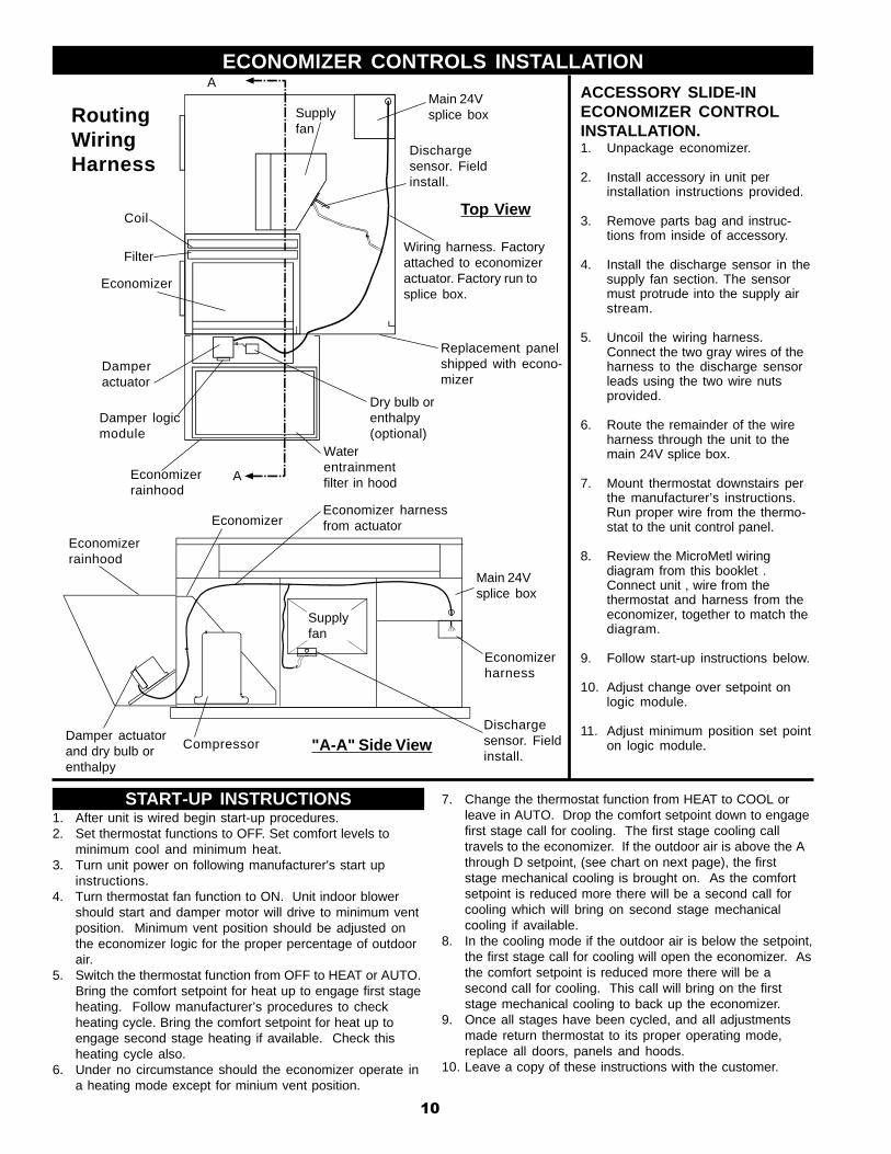
ECONOMIZER CONTROLS INSTALLATIONACCESSORY SLIDE-INECONOMIZER CONTROLINSTALLATION.1. Unpackage economizer.
2. Install accessory in unit perinstallation instructions provided.
3. Remove parts bag and instruc-tions from inside of accessory.
4. Install the discharge sensor in thesupply fan section. The sensormust protrude into the supply airstream.
5. Uncoil the wiring harness.Connect the two gray wires of theharness to the discharge sensorleads using the two wire nutsprovided.
6. Route the remainder of the wireharness through the unit to themain 24V splice box.
7. Mount thermostat downstairs perthe manufacturer’s instructions.Run proper wire from the thermo-stat to the unit control panel.
8. Review the MicroMetl wiringdiagram from this booklet .Connect unit , wire from thethermostat and harness from theeconomizer, together to match thediagram.
9. Follow start-up instructions below.
10. Adjust change over setpoint onlogic module.
11. Adjust minimum position set pointon logic module.
START-UP INSTRUCTIONS1. After unit is wired begin start-up procedures.2. Set thermostat functions to OFF. Set comfort levels to
minimum cool and minimum heat.3. Turn unit power on following manufacturer's start up
instructions.4. Turn thermostat fan function to ON. Unit indoor blower
should start and damper motor will drive to minimum ventposition. Minimum vent position should be adjusted onthe economizer logic for the proper percentage of outdoorair.
5. Switch the thermostat function from OFF to HEAT or AUTO.Bring the comfort setpoint for heat up to engage first stageheating. Follow manufacturer’s procedures to checkheating cycle. Bring the comfort setpoint for heat up toengage second stage heating if available. Check thisheating cycle also.
6. Under no circumstance should the economizer operate ina heating mode except for minium vent position.
7. Change the thermostat function from HEAT to COOL orleave in AUTO. Drop the comfort setpoint down to engagefirst stage call for cooling. The first stage cooling calltravels to the economizer. If the outdoor air is above the Athrough D setpoint, (see chart on next page), the firststage mechanical cooling is brought on. As the comfortsetpoint is reduced more there will be a second call forcooling which will bring on second stage mechanicalcooling if available.
8. In the cooling mode if the outdoor air is below the setpoint,the first stage call for cooling will open the economizer. Asthe comfort setpoint is reduced more there will be asecond call for cooling. This call will bring on the firststage mechanical cooling to back up the economizer.
9. Once all stages have been cycled, and all adjustmentsmade return thermostat to its proper operating mode,replace all doors, panels and hoods.
10. Leave a copy of these instructions with the customer.
A
Economizerrainhood
Damper actuatorand dry bulb orenthalpy
Supplyfan
Dischargesensor. Fieldinstall.
Main 24Vsplice box
Economizerharness
Compressor "A-A" Side View
EconomizerEconomizer harnessfrom actuator
��������������������������������������������������������������������������������������
���������������������������������������������������������������������������������������������������������������������������������������������������������������������������������������������������������������������������������
�������������������������������������������
Waterentrainmentfilter in hood
Economizer
Main 24Vsplice boxSupply
fan
Damperactuator
Damper logicmodule
Dry bulb orenthalpy(optional)
Filter
Economizerrainhood
Wiring harness. Factoryattached to economizeractuator. Factory run tosplice box.
Replacement panelshipped with econo-mizer
Dischargesensor. Fieldinstall.
A
Top ViewCoil
RoutingWiringHarness

11
System Description
These instructions are for fully modulating elec-tronically controlled economizers utilizing solidstate logic throughout. A standard single or
(recommended) two stage thermostat is all that isneeded to complete the control and economizersystem for the HVAC equipment.
Component Description
1. Damper actuator ... 9901-0083 provides 24v modulatingcontrol of economizer dampers, 25 in. lb. of torque.(Honeywell M7415A-1006)
2. Ball joint for linkage connection.
3. Discharge sensor ... 9901-0001 provides a signal (3000Ohms at 25°C or 77°F) to the actuator during free coolingor economizer mode. The signal opens the economizerdamper until the discharge temperature drops below 55°.At this time the signal causes the motor to modulate thedamper and mix outside air with return air to maintain a50° F. to 56° F. discharge temperature.
4. Wire nuts to connect discharge sensor to the harness.
5. Economizer logic ... 9901-0017 accepts input fromdischarge sensor and outside air sensor. Analyzes inputto control actuator modulation and economizer switching.Logic also houses minimum position adjustment andenthalpy or adjustable dry bulb adjustment. When usedwith optional differential sensors in the return air, the logicis capable of selecting the most economical air availablefor cooling. (Honeywell W7459A-1001)
6. Dry bulb...9901-0183 senses temperature of outside airand provides signal to the economizer logic. Opensoutside air at 60°, closes outside air at 70° (enthalpyoptional).
7. 5/8" grommet fits 5/8" hole that wires may pass through tokeep from chaffing.
8. Wire clamps to secure wires to base, dividers, etc..
9. Wire harness color coded and pre-wired to actuator andeconomizer logic... 9962-0087.
10. 1/2" hex head screws to secure wire clamps.
1
4
6
5
3
8
9
2
710

The purpose of an economizer is to use outdoor airfor cooling , whenever possible, to reduce compres-sor operation.
The economizer system initially responds to a signalfrom the cooling thermostat and functions as a truefirst stage for cooling, while providing maximum fueleconomy. The economizer is automatically lockedout during the heating mode and holds the outdoorair damper at the minimum position settings.
During the occupied period, on a call for cooling,when outdoor air temperature or enthalpy (optional)conditions are low, the economizer actuator willproportion to maintain between 50º F and 56º F atthermistor discharge sensor.
If the mixed or discharge temperature is above 56º F,actuator will open to admit additional outdoor air untilthe temperature returns to the 50º to 56º F range. Ifthe mixed or discharge air temperature is below 50ºF, the actuator will proportion closed, shutting theoutdoor air damper until the temperature returns tothe 50º to 56º F range. During the occupied period,the actuator will not close past the minimumposition. 12
MICROMETL INTEGRATED ECONOMIZERS
If the fully open actuator cannot satisfy the spacedemand, mechanical cooling is sequenced on.During the unoccupied period, the actuator willoverride minimum position setting and drive fullyclosed. On a loss of power, the actuator will springreturn fully closed.
When in heating operation, or when outdoor airtemperature or enthalpy (optional) conditions arehigh, economizer operation is locked out, andactuator is held at minimum position.
The staging relay is used when the first stagecompressors must provide mechanical coolingwhen assisting the economizer.
The staging relay can be omitted when the secondstage compressors can be used to assist theeconomizer with mechanical cooling.
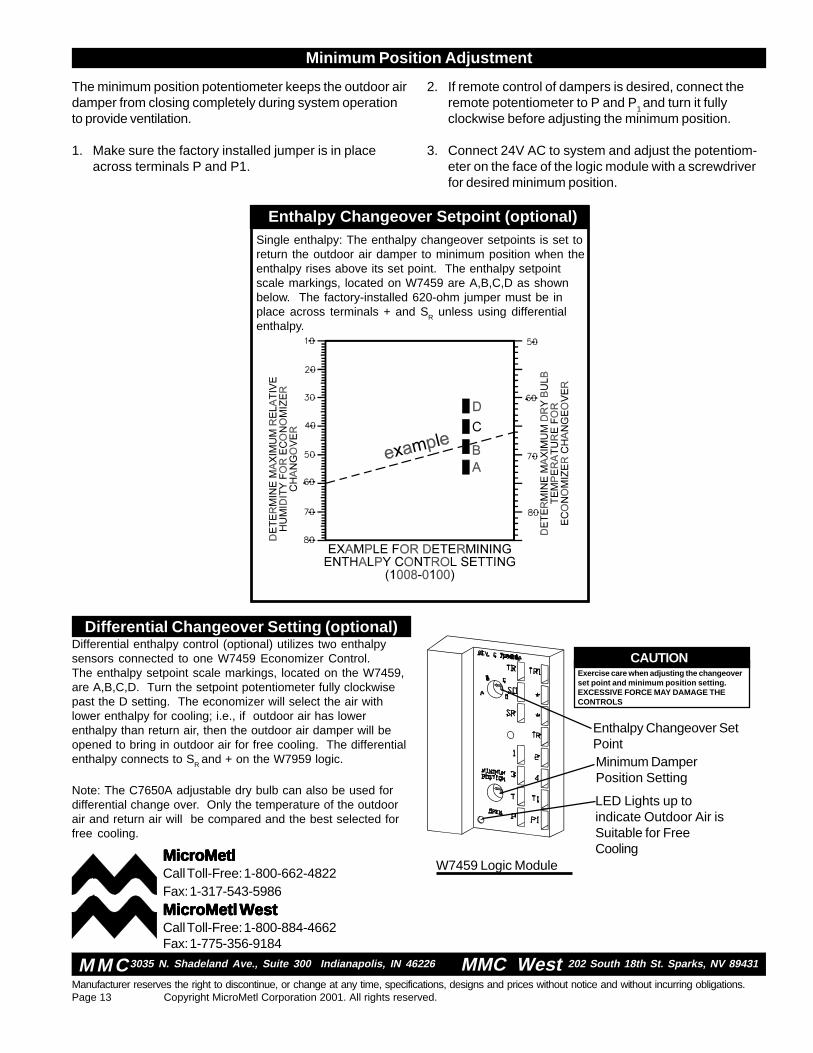
The minimum position potentiometer keeps the outdoor airdamper from closing completely during system operationto provide ventilation.
1. Make sure the factory installed jumper is in placeacross terminals P and P1.
Differential Changeover Setting (optional)Differential enthalpy control (optional) utilizes two enthalpysensors connected to one W7459 Economizer Control.The enthalpy setpoint scale markings, located on the W7459,are A,B,C,D. Turn the setpoint potentiometer fully clockwisepast the D setting. The economizer will select the air withlower enthalpy for cooling; i.e., if outdoor air has lowerenthalpy than return air, then the outdoor air damper will beopened to bring in outdoor air for free cooling. The differentialenthalpy connects to SR and + on the W7959 logic.
Note: The C7650A adjustable dry bulb can also be used fordifferential change over. Only the temperature of the outdoorair and return air will be compared and the best selected forfree cooling.
CAUTIONExercise care when adjusting the changeoverset point and minimum position setting.EXCESSIVE FORCE MAY DAMAGE THECONTROLS
Enthalpy Changeover SetPointMinimum DamperPosition Setting
LED Lights up toindicate Outdoor Air isSuitable for FreeCooling
W7459 Logic Module
Enthalpy Changeover Setpoint (optional)Single enthalpy: The enthalpy changeover setpoints is set toreturn the outdoor air damper to minimum position when theenthalpy rises above its set point. The enthalpy setpointscale markings, located on W7459 are A,B,C,D as shownbelow. The factory-installed 620-ohm jumper must be inplace across terminals + and SR unless using differentialenthalpy.
Manufacturer reserves the right to discontinue, or change at any time, specifications, designs and prices without notice and without incurring obligations.Page 13 Copyright MicroMetl Corporation 2001. All rights reserved.
M M C MMC West
MicroMetlMicroMetlMicroMetlMicroMetlMicroMetlCall Toll-Free: 1-800-662-4822Fax: 1-317-543-5986
MicroMetl WestMicroMetl WestMicroMetl WestMicroMetl WestMicroMetl WestCall Toll-Free: 1-800-884-4662Fax: 1-775-356-9184
Minimum Position Adjustment
2. If remote control of dampers is desired, connect theremote potentiometer to P and P
1 and turn it fully
clockwise before adjusting the minimum position.
3. Connect 24V AC to system and adjust the potentiom-eter on the face of the logic module with a screwdriverfor desired minimum position.
3035 N. Shadeland Ave., Suite 300 Indianapolis, IN 46226 202 South 18th St. Sparks, NV 89431

SUBMITTED TO
COMPANY:
DRAWN BY:JOB NAME:EQUIPMENT:
NOTES:
Part Number:MicroMetl
THIS DOCUMENT IS THE PROPERTY OF MICROMETL CORPORATION AND IS DELIVERED UPON THE EXPRESS CONDITION THAT THE CONTENTS WILL NOT BE DISCLOSED OR USED WITHOUT MICROMETL'S WRITTEN CONSENT.
MICROMETL CORPORATION • 3035 N. SHADELAND AVENUE, SUITE 300 • INDIANAPOLIS, IN. 46226 • 1-800-662-4822 ••• MICROMETL WEST • 202 SOUTH 18TH ST. • SPARKS, NV 89431 • 1-800-884-4662
S U B M I T T A L DATE: 6 / 01
M. HARGIS
Convertible Economizer with Filter Rack for48/50GS 50JS 018-042 48/50GX
50JX, GL 48GP 018-036 (CPECOMZR003A00)0637-0111
Features:• Economizer can be used in a down or horizontal application.• Fully assembled, easy to install in both down and horizontal application.• Modulating control system factory installed and wired (optional).• Filter rack and 1" TAW filters provided. (2 - 12" X 20")• Rainhood ships assembled, includes a water entrainment filterand is constructed of prepaint steel.
• Low leak outside air damper.• Barometric relief damper (for down discharge only).• Insulated filter access door is hinged and latched.
48GS unit Shown in Down
Discharge
Replacement panelshipped witheconomizer
Filter access door forhorizontal application
Economizer'sbarometric relief
damper
Economizeroutside air
damperRainhood with
water entrainmentfilter
Coil
Filters provided
Aluminum waterentrainment
filter
SIDE VIEWDown Discharge
Filter Rack Size
1" filter (2) 12" X 20" X 1"
2" filter(1) 10" X 20" X 2"(1) 12" X 20" X 2"
Hinged andlatched door fordown discharge
filter access
* When using economizer in ahorizontal applications, 2" filters
can not be used.
Supply aircover panel.Shipped onHVAC unit. DPDT Relay (Carrier
part no. HNG1KK040),for heat pump applica-tions, is field provided.

15

IIk 582A-18-13 / 48/50-104SI Catalog No. 534-80092 Page 16