ee2036 flexible ac …
TRANSCRIPT
WWW.VIDYARTHIPLUS.COM
WWW.VIDYARTHIPLUS.COM V+ TEAM
EE2036 Flexible AC Transmission Systems
Two Mark Question and Answers
UNIT I- Introduction
1. What is the necessity of compensation?
The reactive power through the system can significantly improve the performance /
parameters of the power system as follows
Voltage profile
Power angle characteristics
Stability margin
Damping to power oscillations
2. What are the objectives of line compensation?
To increase the power transmission capacity of the line
To keep the voltage profile of the line along its length within acceptable bounds to
ensure the quality of supply to the connected customer as well as to minimize the
line insulation costs
3. How is the reactive power controlled, using FACTS devices?
The SVC is a shunt device of the FACTS group, regulates voltage at its terminals by
controlling the amount of reactive power injected in to or absorbed from the power system.
When a system voltage is low, the SVC generates reactive power (SVC Capacitive). When a
system voltage is high, it absorbs reactive power (SVC inductive)
4. How is reactive power controlled in electrical network?
Traditionally, rotating synchronous condensers and fixed or mechanically switched
capacitors or inductors have been used for reactive power compensation. However, in recent
years static VAR compensators are used to provide or absorb the required reactive power have
been developed.
5. Explain the objectives of FACTS controllers in the power system network.
Better the control of power flow (Real and Reactive) in transmission lines.
Limits SC current
Increase the load ability of the system
Increase dynamic and transient stability of power system
Load compensation
Power quality improvement
6. What are the adv. of FACTS controllers?
The flow of power is ordered. It may be as per the contract or as per the
requirements of the utilities
It increases the loading capability of the lines to the thermal capability
It improves the stability of the system and thus make the system secure

WWW.VIDYARTHIPLUS.COM
WWW.VIDYARTHIPLUS.COM V+ TEAM
Provides secure Tie Line connection to the neighboring utilities and
regions , thereby decreasing overall generation reserve requirements on
both sides
Upgrade of lines
Reduce loop flow
7. List the disadvantage of fixed series compensation.
It is effective only during heavy loads
Whenever an outage occurs on a line, with series compensation, the series
compensation is removed. This may cause overloading of other parallel lines
If series compensation is added to an existing system, it is generally necessary to
have it on all the lines in parallel.
One major drawback in the series capacitance compensation is that special
productive devices are required to protect the capacitors and bypass the high
current produced when a SC occurs
8. What is meant by thyristor switched capacitor?
TCSC is a capacitive reactance compensator, which consists of series capacitor bank
shunted by a thyristor-controlled reactor.
9. Define the term Static VAR compensator.
The SVC is a shunt device of FACTS group using power electronics to control power
flow and improve transient stability on power grids. The SVC regulates voltage at its terminals
by controlling the amount of reactive power injected into or absorbed from the power system.
10. What are the diff types of compensation schemes?
Mainly two types of compensation are carried out,
Load compensation
Line compensation
11. What are the diff power electronic switching devices?
SCR
MOSFET
GTO
IGBT
DOIDE
BJT
12. Define the term FACTS.
Flexible AC Transmission System
Alternating current transmission system incorporating power electronics based
and other static controllers to enhance controllability and increase power transfer
capability
13. What is best location for SVC?
Location of SVC strongly affects controllability of swing modes.
In general the best location is at a point where voltage swings are greatest.
Normally, the midpoint of a transmission line between the two areas is a good
location.
14. Compare fixed series compensation and fixed shunt compensation.
Voltage boost due to shunt compensators is uniform throughout the line.

WWW.VIDYARTHIPLUS.COM
WWW.VIDYARTHIPLUS.COM V+ TEAM
Power factor will be improved by the shunt capacitor whereas, series compensator
improves power system stability limit
Protection required for the series compensator is more compared to shunt
compensator.
Amount of voltage boost by the series capacitor is more
15. What are the main areas of application of FACTS devices?
FACTS mainly find application in following areas,
Power transmission
Power Quality
Railway Grid Connection
Wind power grid Connection
Cable Systems
16. What is load compensation?
Load compensation is a management of reactive power to improve the quality of supply
especially the voltage and power factor levels
Three main objectives of the load compensation are
Better voltage profile
Power factor correction
Load balancing
17. Define VAR compensation.
It is defined as the management of reactive power to improve the performance of AC
power systems: Maximizing stability by increasing flow of active power.
18. List the generation of facts controllers.
The following generation of FACTS controllers for the development of FACTS controllers
First Generation of FACTS controllers:
Static VAR Compensator (SVC)
Thyristor Controlled Series Capacitor (TCSC)
Second Generation of FACTS controllers:
Static Synchronous Compensator (STATCOM)
Static Synchronous Series Compensator (SSSC)
Third Generation of FACTS Controllers:
It is designed by combining the features of previous generations Series and shunt compensation
FACTS controllers.
Unified Power Flow Controller (UPFC)
Interline Power Flow Controller (IPFC)
19. What are various categories of FACTS controllers?
Series FACTS controllers
Shunt FACTS controllers
Combined series series FACTS controllers
WWW.VIDYARTHIPLUS.COM
WWW.VIDYARTHIPLUS.COM V+ TEAM
Combined series shunt FACTS controllers
20. What is IPFC?
Interline power Flow Controller is a combination of two or more independently
controllable static synchronous series compensator (SSSC) which are solid state voltage source
converters which inject an almost sinusoidal voltage at variable magnitude and couples via a
common DC link.
UNIT II- SVC and its Applications
21. Write the application of SVC.
SVC’s are installed to solve a variety of power system problems
Voltage regulation
Reduce voltage flicker caused by varying loads like arc furnace, etc.
Increase power transfer capacity of transmission systems.
Increase transient stability limits of a power system
Increase damping of power oscillations
22. Define the term static VAR compensator (SVC).
Static VAR Compensator is an electrical device, commonly known as SVCs, or
shunt connected devices, vary the reactive power output by controlling or switching the
reactive impedance components by means of power electronics devices. The SVC
regulates voltage at its terminals by controlling the amount of reactive power injected
into or absorb from the power system.
The term “STATIC” refers to the fact that the SVC has no moving parts. Hence it
requires low maintenance.
23. What are advantages of slope in the dynamic characteristics of SVC?
Substantially reduces the reactive power rating of the SVC for achieving nearly
the same control objectives.
Prevents the SVC from reaching its reactive power limits too frequently
Facilitates the sharing of reactive power among multiple compensators operating
in parallel
24. What is the best location for SVC? Justify.
It has been proven that the midpoint of the transmission line is the optimal
location of SVC. This proof is based on the linear load which is not valid
practically
For nonlinear load model it was found that the best location for advanced Static
VAR compensator close to the receiving end where the wide range of reactive
power could be controlled.
25. What are the general characteristics of SVCs?
The lowering of maintenance requirements due to the absence of rotating parts
The very fast control response time
The feasibility of individual phase control
Reduced losses
Highly reliable
26. List the Advantages of SVC.
Cheaper
WWW.VIDYARTHIPLUS.COM
WWW.VIDYARTHIPLUS.COM V+ TEAM
Higher capacity
Faster and more reliable
Simple operation
Improves steady state stability and transient stability
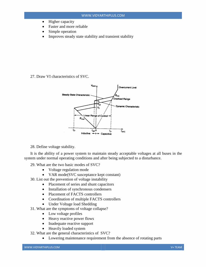
27. Draw VI characteristics of SVC.
28. Define voltage stability.
It is the ability of a power system to maintain steady acceptable voltages at all buses in the
system under normal operating conditions and after being subjected to a disturbance.
29. What are the two basic modes of SVC?
Voltage regulation mode
VAR mode(SVC susceptance kept constant)
30. List out the prevention of voltage instability
Placement of series and shunt capacitors
Installation of synchronous condensers
Placement of FACTS controllers
Coordination of multiple FACTS controllers
Under Voltage load Shedding
31. What are the symptoms of voltage collapse?
Low voltage profiles
Heavy reactive power flows
Inadequate reactive support
Heavily loaded system
32. What are the general characteristics of SVC?
Lowering maintenance requirement from the absence of rotating parts

WWW.VIDYARTHIPLUS.COM
WWW.VIDYARTHIPLUS.COM V+ TEAM
Very fast control response time
Feasibility of individual phase control
Diminished losses
High reliability
Lack of contribution to system short circuit capacity
Generation of harmonics by SVCs except thyristor switched capacitor
Variation of SVC reactive power generation as the square of terminal voltage
when it is operating outside the linear controllable range, leading to a substantial
in reactive power support at a lower voltage
33. Give the applications of synchronous condensers.
Control of large voltage excursions
Dynamic reactive power support at HVDC terminals
34. Give the applications of saturated reactor.
The control of the large voltage excursions
The alleviation of flicker
The reactive compensation HVDC terminal
35. What are the advantages of the slope in the SVC dynamic characteristics?
Substantially reduces the reactive power rating of the SVC for achieving
nearly the same control objectives
Prevents the SVC from reaching its reactive power limits too frequency
Facilitates the sharing of reactive power among multiple compensators
operating in parallel
36. Draw the power angle curve of SVC compensated SMIB system?
37. Where we can locate Svc in a transmission system?
Buses experiencing maximum voltage excursions
Buses where an SVC of a given rating can impart maximum electrical
tamping to the power system
Buses where the critical voltage sensitive loads are connected
The electrical midpoint of transmission line connecting two areas,
maximum voltage swings are likely in the absence of a SVC
UNIT III-TCSC and its Applications
38. Draw the VI Capability curves for Single Module TCSC

WWW.VIDYARTHIPLUS.COM
WWW.VIDYARTHIPLUS.COM V+ TEAM
39. List the advantages of TCSC.
Rapid , continuous control of transmission-line, series-compensation level
Dynamic control of power flow in selected transmission lines within the network
to enable optimal power flow conditions and prevent the loop flow of power
Damping of the power swings from local and inter area oscillations
Suppression of synchronous oscillations
Decreasing DC offset voltages.
40. What is the application of TCSC?
Mitigation of sub synchronous resonance
Enhancement of system damping
Power system stability improvement
To increase power transfer capability
41. What is meant by bypassed thyristor mode?
In this bypassed mode, the thyristor are made to fully conduct with the conduction angle of
180 degree. The TCSC module behaves like a parallel capacitor-inductor combination. However
the net current through the module is inductive, for the susceptance of the reactor is chosen to be
greater than that of the capacitor. Also known as the thyristor switched reactor (TSR) mode
42. What is the indication of voltage collapse points?
The Collapse points are indicative of the maximum load ability of the transmission lines or
the available transfer capability (ATC)
43. What is the effect of TCSC in SSR problem?
At sub synchronous frequency the TCSC presents an inherently resistive-inductive reactance.
The sub-synchronous oscillations cannot be sustained in the situations and consequently get
damped.
44. What are different modes of operation of TCSC?
Bypassed thyristor mode
Blocked thyristor mode
Partially conducting thyristor(Capacitive-Vernier) mode
Partially conducting thyristor(inductive-Vernier) mode
45. What is the need for variable-series compensation?

WWW.VIDYARTHIPLUS.COM
WWW.VIDYARTHIPLUS.COM V+ TEAM
Enhanced base power flow and load ability of series compensator line
Additional losses in the compensator line from the enhanced power flow
Increased responsiveness of the power flow in the series compensated line from
the outage of other lines in the system
46. List the models of TCSC.
Modeling for sub-synchronous resonance SSR studies
Variable reactance model
Transient stability model
Long term stability model
47. How is the variation of capacitive reactance achieved in TCSC?
By varying the firing angle of the anti-parallel thyristor connected in series with the reactor
in the TCR, the fundamental frequency inductive reactance of the TCR can be changed. This
affects a change in the reactance of TCSC and it can be controlled to produce either inductive or
capacitive reactance.
48. Draw the impedance vs. delay angle characteristics of TCSC.
49. Define sub synchronous resonance (SSR)
It is an electric power system condition, where the electric network exchanges energy with
the turbine generator at one or more of the natural frequencies of the combined system below the
synchronous frequency of the system.
50. What are the causes of series compensation in long transmission lines?
Sub-synchronous oscillations, caused by interaction between the electrical
network and the generator torsional system.
Low frequency (1Hz-10Hz) oscillations caused by interaction between the series
capacitors and the shunt inductors, especially during line switching and faults.
These oscillations have large magnitudesand last for long periods because of high
shunt reactor Q factors.
Switching oscillations, caused by the switching of lines.
51. What is TCSC?
WWW.VIDYARTHIPLUS.COM
WWW.VIDYARTHIPLUS.COM V+ TEAM
TCSC is a capacitive reactance compensator, which consists of a series capacitor bank
shunted by a thyristor controlled reactor. The basic conceptual TCSC module comprises a series
capacitor, C,in parallel with a thyristor controlled reactor, Ls, in order to provide a smoothly
variable series capacitive reactance.
52. What is the basic principle of TCSC?
The basic operating principle behind the TCSC is that, it can provide a continuously variable
capacitor by means of partially cancelling the effective compensating capacitance of the thyristor
controlled reactor.
53. What are symptoms of voltage collapse?
The main symptoms of voltage collapse are low voltage profiles, heavy reactive power flows,
inadequate reactive support, and heavily loaded systems.
54. How is voltage instability identified in the power system?
Voltage instability problem is mainly because of insufficient reactive capacity of power
systems during disturbances like line outage contingencies.
Voltage collapse is mathematically indicated when the system Jacobian becomes singular.
55. What does voltage collapse means?
Voltage collapse is a loss of stability in large scale electric power systems which causes
blackout when voltages decrease terribly.
56. How is system voltage stability limit improved?
Voltage stability is primarily associated with the reactive power support. FACTS devices can
regulate the active and reactive power control as well as adaptive to voltage magnitude control
simultaneously because of their flexibility and fast control characteristics.
Placement of these devices in suitable location and proper coordination between FACTS
controllers can leads to control in line flow and maintain bus voltages in desired level and so
improve voltage stability margins and of the power systems.
57. What is Bang Bang control?
Bang Bang control is a discrete control form in which the thyristor are either fully switched
on (α=90) or fully switched off (α=180)
Thus, TCSC alternates between a fixed inductor and a fixed capacitor, respectively, and it is
advantageous that such control is used not only for minimizing first swings but for damping any
subsequent swings as well.
Bang bang control is employed in face of large disturbances to improve the transient
stability.
58. What are the needs for variable series compensation?
Enhance base power flow and load ability of the series compensated line
Additional losses in the compensated line from the enhanced power flow
Increase responsiveness of power flow in the series compensated line from the
outage of other lines in the system
59. What are the advantages of TCSC?
Rapid, continuous control of the transmission line series compensation level

WWW.VIDYARTHIPLUS.COM
WWW.VIDYARTHIPLUS.COM V+ TEAM
Dynamic control of power flow
Damping of the power swings from local and inter area oscillations
Suppression of synchronous oscillations
Decreasing dc offset voltage
Enhanced level of protection for series capacitors
Voltage support
Reduction of the short circuit current
60. Draw the VI capability characteristics for a two module TCSC.
61. Draw a block diagram of the variable reactance model of the TCSC.
62. What are the needs of the damping control of a TCSC?
Stabilize both post disturbance oscillations and spontaneously growing
oscillations during normal operations
Obviate the adverse interactions with high frequency phenomena in power system
such as network resonance
Preclude local instabilities within the controller bandwidth
Be robust in that it imparts the desired damping over a wide range of system
operating conditions
Be reliable
63. What are the locations to place TCSC in a power system?

WWW.VIDYARTHIPLUS.COM
WWW.VIDYARTHIPLUS.COM V+ TEAM
The TCSC should be located in lines that experience limiting power oscillations
The swing of voltage on each side of the TCSC must be within acceptable limits
otherwise multiple sides may be necessary
The control action of the TCSC in one transmission path should not cause undue
power swing in a parallel path
Sometimes it may be advisable to distribute the control action among multiple
TCSCs rather than confining the control action to one large rating TCSC
UNIT IV- Emerging FACTS Controllers
64. What is STATCOM?
The STATCOM (or SSC) is a shunt-connected reactive power compensation device that is
capable of generating and/or absorbing reactive power and in which the output can be varied to
control the specific parameters of an electric power system.
65. State the salient features of STATCOM features.
Compact size
System voltage support and stabilization by smooth control over a wide range of
operating conditions
Dynamic response following system contingencies
High reliability with redundant parallel converter design and modular construction
Flexibility of future reconstruction to Back to Back(BTB) power transmission or
UPFC(Unified Power Flow Control) and other configuration
66. List the application of STATCOM.
Damping of power system oscillations
Damping of sub synchronous oscillations
Balanced loading of individual phases
Reactive compensation of AC-DC converters and HVDC links
Improvement of steady state power transfer capacity
67. Compare the V-I Characteristic of STATCOM & SVC
68. How the reactive power compensation is done using STATCOM.

WWW.VIDYARTHIPLUS.COM
WWW.VIDYARTHIPLUS.COM V+ TEAM
A STATCOM is a controlled reactive power source. It provides the desired reactive power
generation and absorption entirely by means of electronic processing of the voltage and current
waveforms in a voltage source converter
69. List the modes of operation of STATCOM
The STATCOM can be operated in two different modes:
Voltage regulation mode under this mode it has 3 sub divisions. There are,
Over excited mode of operation
Under excited mode of operation
Normal(floating) excited mode of operation
Var control mode
70. Draw VI characteristics of STATCOM.
71. Compare STATCOM and SVC.
The STATCOM has the ability to provide more capacitive reactive power during
faults, or when the system voltage drops abnormally, compared to ordinary static var
compensator. This is because the maximum capacitive reactive power generated by a
STATCOM deceases linearly with system voltage, while that of the SVC is
proportional to the square of the voltage.
Also, the STATCOM has a faster response as it has no time delay associated with
thyristor firing. Nevertheless, these advantages come at a higher price(about 20%
more)
72. What are the function of STATCOM?
Dynamic voltage control in transmission and distribution systems.
Power oscillation damping in power transmission systems
Transient stability improvement
Ability to control not only reactive power but, if needed, also active power (with a
DC energy source available)
73. Define STATCOM.
The STATCOM has been defined as per CIGRE/IEEE with following three operating
scenarios.
First component is static: based on solid state switching devices with no rotating
components;

WWW.VIDYARTHIPLUS.COM
WWW.VIDYARTHIPLUS.COM V+ TEAM
Second component is Synchronous: Analogous to an ideal synchronous machine with
3 sinusoidal phase voltages at fundamental frequency;
Third component is compensator: rendered with reactive compensation.
74. List the advantages/benefits of STATCOM.
The STATCOM offers following advantages:
Superior voltage supporting capability
Fast response
Large reactive power generation under low system voltage condition
Less harmonics generation
Smaller filter capacity
Less space requirement
75. What is UPFC?
The UPFC is a device which can control simultaneously all three parameters of line power
flow(line impedence, voltage and phase angle).Such “new” FACTS device combines together
the features of two “old” FACTS devices” the Static Synchronous Compensator(STATCOM)
and the Static Synchronous Series Compensator (SSSC). It is proposed by Gyugyi in 1991.
76. What is role of dc link in UPFC?
The real power is supplied from, or absorbed by, the DC energy storage device called dc link.
77. List the application of UPFC.
Power flow control
Power swing damping
Voltage dips compensation
Fault Current Limiting
78. State the salient features of UPFC.
The UPFC is versatile and multifunction power flow controller with capabilities of
terminal voltage regulation , series line compensation and phase angle regulation
Minimization of power losses with out generator rescheduling
Regulating power flow through a transmission line
More reliable
Provides dynamic security
Acts as harmonic isolator
79. What are the parameters that can be improved using STATCOM in power system?
The dynamic voltage control in transmission and distribution system
The power oscillation damping in power transmission system
The transient stability
The voltage flicker control
The control of not only reactive power but also active power in the connected
line, requiring a Dc energy source
80. What are the different constraints for operating UPFC?
The series injected voltage magnitude
The line current through series converter
The shunt converter current
The minimum line side voltage of the UPFC
WWW.VIDYARTHIPLUS.COM
WWW.VIDYARTHIPLUS.COM V+ TEAM
The maximum line side voltage of the UPFC
The real power transfer between the series converter and the shunt converter
81. What are the operating modes of UPFC?
VAR Control Mode
Automatic Voltage Control Mode
Direct Voltage Injection Mode
Phase Angle Shifter Emulation Mode
Line Impedance Emulation Mode
Automatic Power Flow Control Mode
UNIT V- Coordination of FACTS Controllers
82. Define the term “Co-ordination”
The term coordinated implies that the controllers have been tuned simultaneously to effect an
overall positive improvement of the control scheme
83. How is coordination of FACTS controllers carried out?
Controller interactions can occur in the following combinations:
Multiple FACTS controllers of a similar kind
Multiple FACTS controllers of a dissimilar kind
Multiple FACTS controllers and HVDC converter controllers
84. What is the need for coordination of different FACTS controllers?
Need for coordination
Adverse interaction due to fast controls
Usually controls are tuned optimally assuming the remaining power system to be
passive
Above parameters not optimal when dynamics of other controller are existent ( Power
System Stabilizers(PSS),HVDC,FACTS)
85. What do you understand by coordination of FACTS controllers?
The term coordinated implies that the controllers have been tuned simultaneously to effect an
overall positive improvement of the control scheme
86. What is genetic algorithm (GA)?
GA is global search technique based on mechanics of natural selection and natural
genetics. It is a general purpose optimization algorithm that is distinguished from
conventional optimization techniques by the use of concepts of population genetics to
guide the optimization search.
These techniques provide robust, decentralized control design and are not restricted
by problems of non-differentiability, non-linearity, and non-convexity, all of which
are often limiting in optimization exercises.
87. List the advantages of genetic algorithm.
An advantage of genetic algorithm techniques is that the parameter limits can be varied
during the optimization, making the techniques computationally efficient.
88. List the possible combination of FACTS controller interactions.

WWW.VIDYARTHIPLUS.COM
WWW.VIDYARTHIPLUS.COM V+ TEAM
Multiple FACTS controllers of a similar kind
Multiple FACTS controllers of a dissimilar kind
Multiple FACTS controllers and HVDC converter controllers
89. Give The frequency range of the different control interactions
0 Hz for steady state interactions
0-3Hz for electromechanical oscillations
2-15Hz for small signal or control oscillations
>15 Hz sub synchronous resonance interactions
>15 Hz for electromagnetic transient high frequency resonance or harmonic
resonance interactions, and network resonance interactions
90. What are the basics procedures of the controller design?
Derivation of the system model
Enumeration of the system performance specifications
Selection of the measurement and control signals
Coordination of the controller design
Validation of the design performance evaluation
91. Write the assumptions of control coordination for damping enhancement?
All controllers in the system including FACTS have the transfer function of the
type kjGj (S)
The component Gj(S) in the transfer function is responsible for causing the left
shift in the electromechanical mode
The gain Kj in the transfer function decides the magnitude of left shift in the
mode of interest