electricalpartmanuals ele… · · 2011-09-12standard low voltage wiring connecting...
TRANSCRIPT
www . El
ectric
alPar
tMan
uals
. com

• Remote Control Low Voltage Switching Components and Applications CONTENTS PAGE
Overview . . . . . . . . . . . . . . . . . . . . . . . . . . . . . . . . . . . . . . . . . . . . . . . . . . . . 1
Principles of Operation . . . . . . . . . . . . . . . . . . . . . . . . . . . . . . . . . . . . . . 2-3
Components
Relays .................................................... 4-5
Power Supply (Transformer/Rectifiers) ......................... 6-7
Switches and Plates . . . . . . . . . . . . . . . . . . . . . . . . . . . . . . . . . . . . . . 8-11
Controls/Master Grouper .................................... 12
Master Sequencer . . . . . . . . . . . . . . . . . . . . . . . . . . . . . . . . . . . . . . . . 13
Telephone Override ....................................... 14
Photo Switches . . . . . . . . . . . . . . . . . . . . . . . . . . . . . . . . . . . . . . . . . . 15
Component Cabinets . . . . . . . . . . . . . . . . . . . . . . . . . . . . . . . . . . . . 16-17
Wire . . . . . . . . . . . . . . . . . . . . . . . . . . . . . . . . . . . . . . . . . . . . . . . . . . . . . . 16
Replacement Parts . . . . . . . . . . . . . . . . . . . . . . . . . . . . . . . . . . . . . . . . . 17
Basic Circuits and Applications
Standard Low Voltage Wiring
Connecting Switches/Relays/Power Supply .................. 20
Central/Local Switch Control of Relays ...................... 21
Pilot Light Status Indication ................................ 22
Switch Lockout ........................................... 22
Master Control of Grouper Using RCBD12 ................... 23
Selective Switching Using RCBD12 ......................... 23
Simple Automation
Master Sequencer
Master Control of Group of Relays .......................... 24
Global Master Switch With Local Panel Masters .............. 24
Timeclock/Building Automation Control . . . . . . . . . . . . . . . . . . . . . . 25
Daylighting Control ....................................... 25
Telephone Override (With Master Control)
Telephone Override of Individual Relays ..................... 26
Master Switch Control . . . . . . . . . . . . . . . . . . . . . . . . . . . . . . . . . . . . . 27
Telephone Master Control ................................. 27
Limiting the Operation of Telephone ......................... 27
Typical Component Panel Assembly . . . . . . . . . . . . . . . . . . . . . . . . . . 28
Catalog Number Index Catalog Number Page BPHOT0-4 . . . . . . . . . . . . 15 BPHOT0-5 . . . . . . . . . . . . 15 GE 5099-0 ............. 11 GE 5931-N0-1 G ....... 11 GE 5935-1G ........... 11 GE 5935-2G ........... 11
GE 5935-9G . . . . . . . . . . . 11
P-RR7L ............... 19 P-RR8L ............... 19 P-RR9L ............... 19 RA 12 ................. 19 RA 13 ................. 19
RA 14 ................. 19 RA 15 ................. 19 RA 16 ................. 19 RA 20 ................. 19 RA 2-32 ................ 8 RA 2-32-L .............. 8
RA 2-37 ................ 8 RA 2-37-L .............. 8 RA 2-38-P .............. 8 RA 2-QC ............... 8 RB3EZ ................ 16 RB3-CFEZ . . . . . . . . . . . . 16
RBF 1 ................. 17 RBS 1 ................ 17 RBF 2 ................. 17 RBS 2 ................ 17 RCBD 1 ............... 19
RCBD12 .............. 12 RCS 2 ................ 19
RCS 2PL .............. 19 RFS 6 ................. 19 RFT178EZ. . . . . . . . . . . . . 17 RFT278EZ . . . . . . . . . . . . . 17
RKO ................... 8 RK 1 .................. 10 RKS 6 ................ 19 AMP 2-35 ............. 10
RMS 4A ............... 19 RMS8 ................. 13 RMS16 ................ 13 RMS32 ................ 13 RP 1 .................. 19 RP 2 .................. 19 RP 2-N1 ............... 11 RP 2-N3 ............... 11
RP 3 .................. 19 RP 24 ................. 19 RP 211 ................ 19 RP 212 ................ 19 RP 213 ................ 19
RP 224 ................ 19
RP 229 ................ 19
RP 2-111 ............... 9
RP 2-112 ............... 9
RP 2-116 ............... 9
RP 2-117 ............... 9
RP 2-121 ............... 9
RP 2-122 ............... 9
RP 2-126 ............... 9
RP 2-127 ............... 9
RP 2-231 ............... 9
RP 2-232 ............... 9
RP 2-236 ............... 9
Catalog No. Page
RP 2-237 ............... 9 RP 2-241 ............... 9
RP 2-242 ............... 9 RP 2-246 ............... 9 RP 2-247 ............... 9 RP 311 ................ 19
RP 312 ................ 19 RP 313 ................ 19 RP 324 ................ 19 RPB 2-1 ................ 9 RPB 2-2 ................ 9
RR 7 ................... 4
RR 7EZ ................ 4 RR 8 ................... 4 RR 8EZ ................ 4 RR 9 ................... 4 RR 9EZ ................ 4 RRF 78EZ ............. 17
AS 2-32 ................ 8 AS 2-32K ............... 8 AS 2-32L ............... 8 AS 2-32LK ............. 8 AS 2-32P ............... 8
AS 2-32PK ............. 8 AS 2-32RL ............. 8 AS 2-37 ................ 8 AS 2-37K ............... 8 AS 2-37L ............... 8 AS 2-37LK ............. 8 AS 2-37P ............... 8
AS 2-37PK ............. 8
AS 2-37RL ............. 8 RSWIRE-3(P) .......... 18 RSWIRE-4(P) .......... 18 RSWIRE-25(P) ......... 18
RSWIRE-5(P) .......... 18 AT 1 ................... 6 RT 2 ................... 6 AT 4 ................... 6 RT 5 ................... 6 71011 ................. 11 71021 ................. 11 71031 ................. 11 72011 ........... ...... 11 72021 ................. 11 72031 ................. 11 97011 ................. 11 97031 ................. 11 97041 ................. 11
0
www . El
ectric
alPar
tMan
uals
. com

Overview Remote Contro l components provide the basic bui lding b locks tor a flexible lighting control system. The standard components are assembled to provide the specific control functions required by the bui lding. The new "EZ" electronic controls and components simplify both design and insta llation. The new preassemb led " EZ- Panels" provide the most common panel control configurations in economica l standard assemb lies
Feature/Benefit Summary
Low Voltage Wiring ( Figure 1)
Multiple Switch Control of a Single Relay .. Simplifies central and local control of lighting and makes it
possible to readily control lighting from several locations.
Pilot Light Status Indication .. Provides visua l indication of lighting status at remote
switching location. Relay Grouping for Common Control
Simple, low cost "multi-pole lighting contactor function". Circuits can be grouped tor common control and reconfigured as the bu ilding layout changes without attecting the line-voltage wiring.
Reduced Wiring Costs .. Smal l low-vo ltage cables rep lace costly line vo ltage wiring
and conduit. Particular ly important tor long switchlegs.
Simple Lig hting A utom ation
Manual or Automatic Master Control with Local Switch Override ( Figure 2)
.. Local and Remote Master Switches make it possible to manually control a f loor or department and still allow �n individual to override his local lighting . Timeclocks or the building automation system can readily control the lighting automatically. Loca l switch override makes the system responsive to the unpredictable needs of occupants.
Manual or Automatic Master Control with Telephone Override (Figure 3)
.. Simi lar to above except the existing Touchtone'" phones may be used instead of hardwired switches. Saves installation labor while providing a convenient switching method tor occupants ... particularly e ttective in open ottice areas or tor the control of remote loads or buildings.
Note: Figures 1 , 2, and 3 are one line drawings illustrating the control concepts. Refer to the next section for more detail.
which simplify design and instal lation. The low voltage latching relay which is the heart of the system is common to al l General E lectric lighting controls ... standard Remote Control Components, Smart Remote Control, and Programmable Lighting Contro l. Thus, installing a Remote Control component system not only provides the building's basic control needs, it ensures that the lighting controls can be upgraded in the future.
LOAD
r�-�+----.1--------��---�-� � LIGHT
SWITCH
p-LOW VOLTAGE WIRING
FIGURE 1. Low Voltage Wiring
ON OFF
MASTER SWITCH
L�-�r---·: . ----L_J
RELAY (S)
......... ·-
LOAD
FIGURE 2. Lighting Automation with Local Switch Override
TELEPHONE EXTENSION
TELEPHONE OVERRIDE WITH MASTER SWITCHES
MASTER SWITCH
FIGURE 3. Lighting Automation with Telephone Override
www . El
ectric
alPar
tMan
uals
. com

Principles of Operation Relays ... the Heart of the System (pages 4-sJ
RR7 Oper ation The relay employs a split low-voltage coil to move the line voltage contact armature to the ON ( O F F) latched position. As illustrated, the O N coil moves the armature to the right when a 24 VAC control signal is impressed across its leads. This is analogous to a magnet attracting the handle of a standard single pole switch to the O N position when energized. The armature (handle) latches in the O N position and will remain there until the O F F coil is energized, drawing the armature into the O F F position.
This control operation provides several key control features:
1. Positive action The relay always goes to the state commanded. For example, multip le O F F commands will simply keep the contacts in the O F F position.
2. Stable operation Since the relay latches in the O N or O FF position, power outages do not result in a change-of-state.
3. Minimal power consumption Control power is only required when the relay changes state.
4. Additive control functions Pulse control signals coupled with latching allows any number of switches or electronic control devices to operate the same relay. The relay position is always dictated by the last signa l.
RR8 and RR9 The R RB and R R9 each include an auxiliary contact on the low-voltage side to provide status indication. The auxiliary contact in the R R8 is internally wired to provide 24VAC power to the status lead for direct wiring to pilot switches or indicator lights. The R R9 contact is isolated.
ON (RED)
24 VAG (RECTIFIED)
OFF (BLACK)
"ON"
"OFF"
_j_ •
_j_
FIGURE 4. Relay Operation
20 AMP. 277 VAG (LINE CONTACTS)
LOAD
LOAD
Power Supplies ... Transformers/Rectifiers (pages 6-7J
The RT1 ( R T2) transformer supplies 24 VAC power to operate the relays and their controls. The relay and pilot switch power is rectified to extend their life; electronic control component power is not rectified.
2
24 VAG I
} TO RELAYS AND PILOT LIGHTS
LINE � � ± • . RECTIFIER
VOLTA __ : __ ---t --H--
TRANSFORMER L·'. .. L -·-·- -·
···· } TO POWER INPUT
(RT 1, RT 2) OF ELECTRONIC #20 OR LARGER CONTROLS
FIGURE 5. Power Supply
www . El
ectric
alPar
tMan
uals
. com

Switches (pages a-11) Stand ard The standard low-voltage switch uses a r ocker or tw o-butt on c onfigurati on t o pr ovide a m omentary sing le-pole, double throw acti on. Pushing the ON ( O FF) button completes the circuit t o the ON ( OF F) c oi l of the relay shifting the c ontact armature t o the c orresp onding p osition. When the button is re leased, the relay remains in that position. The pu lse operati on a l l ows any number of switches t o be wired in para l lel as sh own. A gr oup of relays c ou ld a ls o be wired for c ommon switch control by para l le ling their c ontrol leads. Those relays w ould then operate as a group.
Pilot Pilot switches include a lamp wired between the switch c ommon (white) and a pi l ot terminal. The auxiliary c ontact in the R RB relay pr ovides power t o drive this lamp when the relay is ON.
Controls (pages 12-13)
M aster Sequencer The Master Sequencer all ows re lays t o be c ontrol led as a gr oup whi le sti ll a ll owing individual switch c ontrol of each. When the Master Switch is turned ON ( O FF), the Sequencer pu lses each of its ON ( O F F) relay outputs sequentially. A l ocal switch can c ontr ol an individua l relay without affecting any others. A second input channe l a l l ows timec locks, bui lding aut omati on system outputs, ph otoce l ls or other maintained contact devices t o a ls o c ontrol the Sequencer. This provides simp le automati on c oupled with l oca l override of individual l oads.
Telephone Override with M aster Switches The Te lephone Override ( RT EL) provides the same c ontr ol functions as the Sequencer; but in additi on, it a ll ows the occupant's Toucht one'" phone t o be used in lieu of (or in additi on to) hardwired switches as i l lustrated be l ow. "Special Function" switches on the RT EL als o all ow the phone override function t o be disabled or to be limited to " ON" overrides on ly.
"Touchtone" is a registered trademark of AT&T.
CALL RTEL·s EXTENSION
·HING ..... "BEEP .. (Wait for BEEP
to end. )
EN ER OUTPUT# .. ACTION ... # (1_16) (0 �OFF 1 �ON)
FIGURE 6. Switch Operation
POWER INPUT
- MASTER SWITCH -- 1 2 -- A B COM A B COM -
FIGURE 7. Master Sequencer
RTEL·s TELEPHONE EXTENSION
TIMECLOCK (Optional)
FIGURE 8. Telephone Override
TO OTHER RELAYS IN GROUP
(MAX 1 OF 3
IN PARALLEL)
==e=[J2 !
16
(POWER SUPPLY CONNECTIONS NOT SHOWN)
(POWER SUPPLY CONNECTIONS NOT SHOWN)
3 www . El
ectric
alPar
tMan
uals
. com
Components Relays
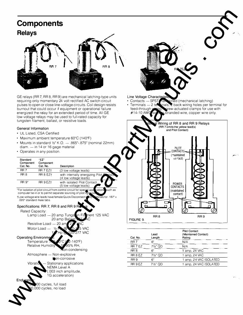
G E relays ( R R 7, R R 8, R R 9) are mechanical latching-type units requiring only momentary 24 volt rectified AC switch circuit pulses to open or close line-voltage circuits. Coil design resists burnout that could occur if equipment or operational failure energized the relay for an extended period of time. All GE low-voltage relays may be used to full-rated capacity for tungsten filament, ballast, or resistive loads.
General Information
UL Listed, CSA Certified
• Maximum ambient temperature 60°C ( 140°F)
• Mounts in standard W' K.O. - .865"-.875" (nominal 22mm) diam.- in 14 or 16 gage material
• Operates in any position .
Standard Component Cat. No.
RR 7 RR 8
RR 9 *
"EZ" Component Cat. No.
RR 7 EZt RR 8 EZt
RR 9 EZt
Description
(3 low voltage leads) with internally energizing Pilot Contact (4 low voltage leads)
with isolated Pilot Contact (5 low voltage leads)
*For isolation of pilot circuit from control circuit for special applications, such as computer t1e-in or to permit separate sourcing of pilot light power.
tLow-voltage wire leads have female Quick Disconnect (OD) terminals for . 187" x .020" standard male tabs.
Specifications: RR 7, RR 8 and RR 9 Relays
Rated Capacity : Lamp Load -20 amp Tungsten Filament 125 VAC
20 amp Ballast 2 7 7 VAC Resistive Load- 20 amp 2 77 VAC
Motor Load- V2 Hp@ 110- 125 VAC 1 V2 Hp @ 220-2 77 VAC
Operating Environment: Temperature - 0-60°C (32-140°F) Relative Humidity- 10-95% R H,
Non-condensing
Atmosphere - Non-explosive Non-corrosive
Vibration -Stationary applications N EMA Level A (.003 inch amplitude, 1 G acceleration)
Endurance:
4
50,000 cycles, full load 100,000 cycles, no load
Line Voltage Characteristics • Contacts- SPST maintained (mechanical latching) • Terminals - 2 terminals, 2 back wiring holes per terminal for
feed-through wiring, screw-actuated clamps for use with #1 4-1 0 AW G solid or stranded wire, copper wire only .
FIGURE 9.
Cat. No.
RR 7
RR 7 EZ
RR 8
RR 8 EZ
RR 9
RR 9 EZ
Internal Wiring of RR 8 and RR 9 Relays (RR 7 omits the yellow lead(s)
ARB
Lead Length
6"
7W'QD 6"
7W'OD
6"
7W'OD
and Pilot Contact)
POWER CONTACTS
RR 9
Pilot Contact (Maintained Contact) Rating
N/A
N/A 1 amp, 24 VAC
1 amp, 24 VAC
1 amp, 24 VAC ISOLATED
1 amp, 24 VAC ISOLATED
www . El
ectric
alPar
tMan
uals
. com
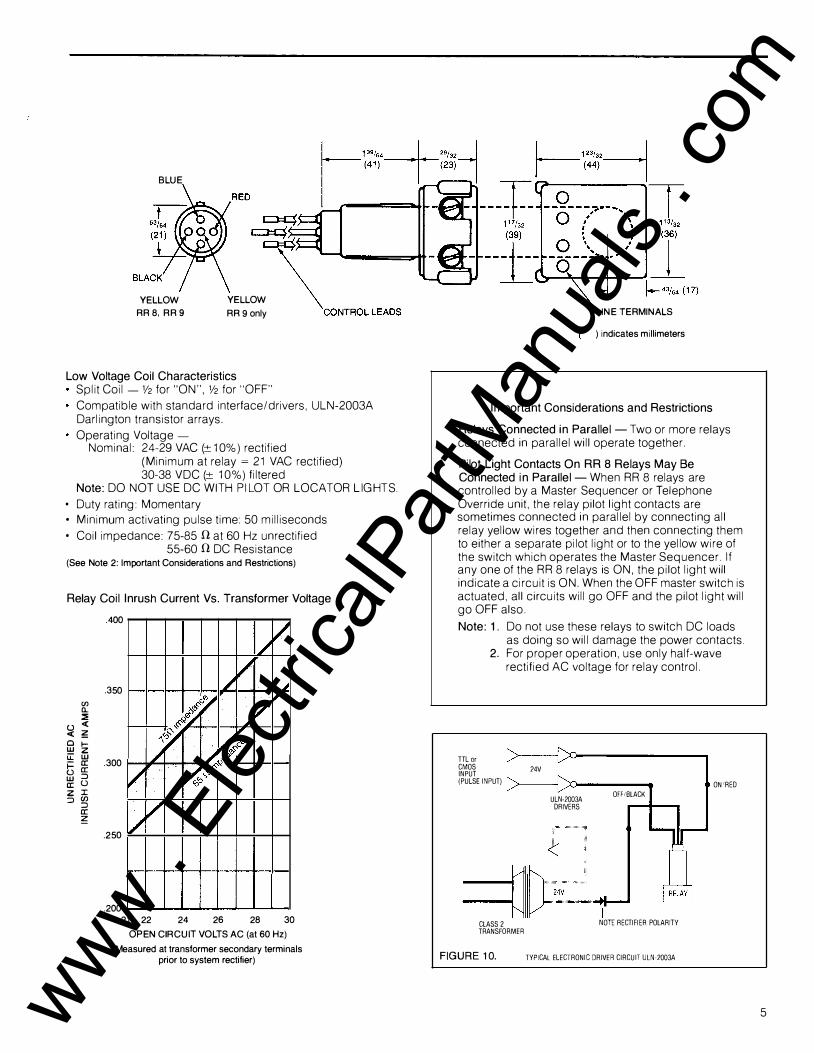
BLUE
YELLOW RR 8, RR 9
YELLOW
RR 9 only
Low Voltage Coil Characteristics Split Coil - V2 for "O N", V2 for "O F F"
Compatible with standard interface/drivers, ULN-2003A Darlington transistor arrays.
Operating Vo ltage -Nominal: 2 4-29 VAC (± 1 0%) rectified
( Minimum at relay = 21 VAC rectified) 30-38 V DC (± 10%) filtered
Note: D O N OT USE DC W ITH PILOT OR L OCATOR LIG HTS.
• Duty rating: Momentary • Minimum activating pulse time: 50 milliseconds
• Coil impedance: 75-85 11 at 60 Hz unrectified 55-60 11 DC Resistance
(See Note 2: Important Considerations and Restrictions)
Relay Coil Inrush Current Vs. Transformer Voltage
(J) ll. ::!:
(.) <{ <{ � Cl 1-w z u:: w i= rr: (.) rr: w ::::J rr: (.) z I ::::><Jl ::::J rr:
�
. 400
.350
.300
/ .250 /
.200
/ v � '/><::' � �� �
�y �� / � �'/><::' Qe -� k; '>' co":>
/ /
/
v
v II"
21 22 24 26 28 30
OPEN CIRCUIT VOLTS AC (at 60Hz)
(Measured at transformer secondary terminals prior to system rectifier)
LINE TERMINALS
) indicates millimeters
Important Considerations and Restrictions
Relays Connected in Parallel- Two or more relays connected in parallel will operate together.
Pilot Light Contacts On RR 8 Relays May Be Connected in Parallel- When RR 8 relays are controlled by a Master Sequencer or Te lephone Override unit, the relay pilot light contacts are sometimes connected in parallel by connecting all relay yel low wires together and then connecting them to either a separate pilot light or to the yellow wire of the switch which operates the Master Sequencer. If any one of the RR 8 relays is O N, the pilot light wi ll indicate a circuit is O N. When the O F F master switch is actuated, all circuits will go O F F and the pilot light will go O F F also .
Note: 1. Do not use these relays to switch DC loads as doing so will damage the power contacts.
2. For proper operation, use only half-wave rectified AC voltage for relay control.
TTL or CMOS INPUT (PULSE INPUT)
CLASS 2 TRANSFORMER
F IGURE 10.
24V
ULN-2003A DRIVERS
OFFIBLACK
t NOTE RECTIFIER POLARITY
TYPICAL ELECTRONIC DRIVER CIRCUIT ULN-2003A
ON•RED
5 www . El
ectric
alPar
tMan
uals
. com

Power Supplies Transformers
The transformers provide the low-voltage power (29 VAC open circuit) for relay actuation and for low-voltage accessories. Because individual relay coils are only energized for a very short period of time, the demand factor is extremely low and one transformer can supply a large number of relays.
Component Cat. No.
RT 1
RT 2
Description
11 8 VAC 60Hz transformer primary, 75 volt- amp momentary, 40 volt- amp continuous for 2 4 volt systems
277 VAC 60Hz transformer primary, 75 volt-amp momentary, 40 volt- amp continuous for 2 4 volt systems
General Information
o Suitable for Class 2 signal systems (U.S. National Electric Code -Article 725, and Canadian Electric Code -Section 16)
o UL Listed, CSA Certified o Overload Protected
Switch Runs and Voltage Drops
Under normal operating conditions using RA 16 rectifier and RT 1 transformer with 118 VAC primary or RT 2 transformer with 277 VAC primary, the following table is useful in determining wire size, permissible length of run, and number of relays that can satisfactorily operate in parallel.
Note: The figures have been calculated based on least ideal operating conditions likely to be encountered.
Maximum Switch Leg Length in Feet (Meters) using one RT 1 or RT 2 Transformer Switch
�G���������������������������]s�w�itc�h�L�e�g�Le�n�g�th�==================�� Relay ?S Transformer "T"?
Number of Relays• or Equivalent t in Parallel # 12 AWG
1 10000 (3048)
2 4850 (1 47 8) 3 3000 (91 4) 4 2100 ( 6 40) 5 1550 ( 472) 6 1150 (350) 7 900 (27 4)
8 700 (213)
9 550 (16 8)
10 425 (130) 11 325 (99)
12 2 40 (73)
13 175 (53) 1 4 110 (34) 15 55 (17)
RR 7 RR 8 and RR 9 Relays
WIRE SIZE
#14AWG #16 AWG #18AWG
6500 (19 81) 4000 (1219) 2550 (777)
3000 (91 4) 1900 (579) 1200 (366) 1900 (579) 1200 (366) 750 (229)
1300 (396) 825 (251) 500 (152) 950 (290) 600 (1 83) 375 (114) 725 (221) 450 (137) 300 (91) 650 (19 8) 350 (107) 225 (69)
450 (137) 275 ( 8 4) 175 (53)
350 (107) 225 ( 69) 135 ( 41)
250 (76) 160 ( 49) 100 (50) 200 (61) 125 (38) 80 (2 4)
150 ( 46) 90 (27) 60 (1 8)
100 (30) 60 (18) 40 (12)
65 (2or 40 (12)
35 (11)
•11 the application approaches the maximum sw1tching length, a Master Sequencer may be advisable. (See page 13 ) ·For applications w1th five or more relays in parallel, the use of Master Sequencers may be advisable. (See page 13.)
#20 AWG
1600 ( 48 8)
750 (229) 450 (137)
325 (99) 2 40 (73)
1 80 (55)
140 ( 43)
110 (34)
85 (26)
65 (20) 50 (15)
35 (11)
tCount each Pilot Light Switch or Accessory as 1/s relay, Locator Light Switch or Accessory as 1!12 relay, Master Sequencer or Telephone Controller as 1 Relay.
-
Note: If a Remote Control Block1ng Diode Assembly RCBD 1 (or RCBD 12) is used, reduce the above distances by 40%. Do not use smaller than 1120 AWG control wires in this system. If there are questions about a particular circuit, please contact your local GE Wiring Device Representative
6 www . El
ectric
alPar
tMan
uals
. com

-
Important Considerations and Restrictions
When more than one transformer is used in accordance with U.S. National Electric Code Section 725-32 and Table 725-31 (a) and control devices are operated by a common switch, connect the WHIT E low voltage secondary commons of both transformers by a common wire. Transformer primaries must be wired identically (correct polarity) to the same phase. Such installations are not permitted in Canada by Canadian Electric Code C22.1 Subrule 16-200 (4).
Factors that influence the calculation of power requirements are:
a) maximum number of relays connected in parallel in any one circuit
b) length of switch leg
c) wire size d) number of electronic controls and low-voltage
accessories that might be operated simultaneously
e) number of pilot lights and locator lights in the switching circuits
Current draw of these components is given in each component description.
RT 1, RT 2
1+---3�9/, •. __ -+l (91)
Flange fits 3W' and 4" octagon box or 4" square box.
�(�6�---1 0.
) indicates millimeters
Rectifiers
RA16
The RA 16 rectifier is recommended for longer life of G E relays, pilot lamps and locator lamps.
oN\Pv OP,�0 n Time-
Unrectified sinsoidal voltage trace Half-wave rectified
sinsoidal voltage trace
General Information
• Heavy duty silicon rectifier
• Affords protection to the switching system
• Provided in G E "EZ" component cabinets. Rating
• 20A 30 VAC intermittent duty
• 7.5A 30 VAC continuous duty
Component Cat. No. Description
RA 16 Silicon rectifier assembly
) indicates millimeters
Anode Terminals (unrectifled voltage input)
,':,..J \+a;, . 25/32� (S)
(55)
RA 16
7 www . El
ectric
alPar
tMan
uals
. com

Specifier Series Master Plate
-·
RMP 2-35
Key opening for Frame Mounted Lockout Switch
The master plate is used for convenient ganging of 8 switches or accessories.
One key-operated lock-out switch is provided in the frame which may be used to electrically deactivate any or all of the switches in the plate. The lock-out switch must not be used when two or more lighted switches are connected in parallel because feedback will occur in the pilot light circuit, causing the lamps to remain "ON" dim ly. The lock-out switch will cut out indicator lamps on lighted switches and accessories using the white (common) wire on this plate.
General Information
o Master p late accepts eight RS 2 series switches and/or RA 2 series accessories.
o Satin finish, anodized aluminum frame on zinc diecast base.
o Built-in locking switch, with one RK 1 key.
o Directory for identifying individual circuits holds typed e lite size letters or W' embossing tape such as Dymo®.
o Mounts directly on 411/,6" square boxes using "S" bracket packed with unit. (May NOT be mounted on 4" square box).
Cat. No. Description
RMP 2-35 8- switch opening master plate
RK 1 Key, replacement ( 1 furnished with master plate)
Color
aluminum with black trim
Dymo® is a registered trademark of Dymo Industries, Inc.
(-;�
) I 4.88 ----� ----(1 24)
L-rr========;i
3.48 (88)
4.88 j .40 (1 24) (1 0)
11_
10
t . 82 (21 )
Backview
--- + 1 . 28 (33) _j_
.20+- ··
(5) 1 . 28 ------jE1-:tJ=::'::= (33)
____ 3.42 --(87)
---4.05 ---; (1 03)
t ----t
.22 I I I (6) ""1 ... .44
... 1 --(11)
RMP 2-35 shown with switches (purchase switches and accessories separately).
Installing Master Selector Switches
Four Master Plates are shown below in gang mounting. Note positioning of boxes to permit horizontal installation of mounting brackets. For multi-switch applications, the master plate is ideal for small, neat-appearing insta llations. These plates mount directly on 411 /16" square boxes without plaster rings. The boxes must be mounted so that the two mounting-screw tabs are on the sides of the box- not at top and bottom.
Mounting with 411/,s" (119) boxes:
) indicates millimeters
-
www . El
ectric
alPar
tMan
uals
. com
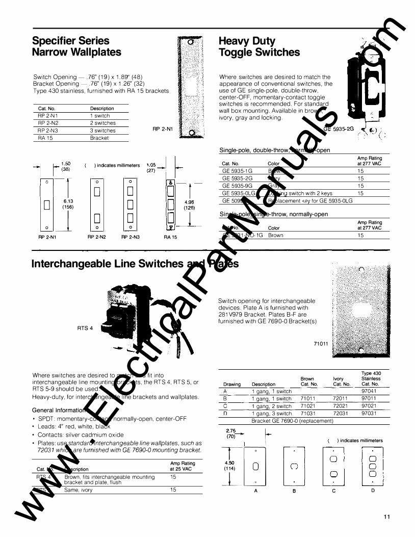
Specifier Series Narrow Wallplates
Switch Opening-. 76" (19) x 1.89" (48) Bracket Opening- . 76" ( 19) x 1.26" (32) Type 430 stainless, furnished with RA 15 brackets
Cat. No.
RP 2-N1 RP 2-N2
RP 2-N3 RA 15
0
6.13 (156) o_j
RP 2-N1
Description
1 switch 2 switches
3 switches
Bracket
) indicates millimeters
0
D
0
0
RP 2-N2
0
D
0
0
0
RP 2-N3
RP 2-N1
RA15
Heavy Duty Toggle Switches
Where switches are desired to match the appearance of conventional switches, the use of G E single-pole, double-throw, center- O F F, momentary-contact toggle switches is recommended. For standard wall box mounting. Available in brown, ivory, gray and locking.
Single-pole, double-throw, normally-open
Cat. No. Color
GE 5935-1G Brown
GE 5935-2G Ivory
GE 5935-9G Gray
GE 5935-0LG Locking switch with 2 keys
GE 5099-0 Replacement key forGE 5935-0LG
Single-pole, single-throw, normally-open
Cat. No. Color
G E 5931-N0-1 G Brown
Amp Rating at277 VAG
15
15
15
15
Amp Rating at277VAC
15
Interchangeable Line Switches and Plates
RTS 4
Where switches are desired to match and fit into interchangeable line mounting brackets, the RTS 4, RTS 5, or RTS 5-9 should be used.
Heavy-duty, for interchangeable line brackets and wallplates.
General Information
• S POT: momentary-contact, normally-open, center- O F F • Leads: 4" red, white, black
• Contacts: silver cadmium oxide
• Plates: use standard interchangeable line wallplates, such as 72031 which are furnished with GE 7690-0 mounting bracket.
Cat. No. Description
RTS 4 Brown, fits interchangeable mounting bracket and plate, flush
RTS 5 Same, ivory
Amp Rating at 25 VAC
15
15
Switch opening for interchangeable devices. Plate A is furnished with 281 V979 Bracket. Plates B-F are furnished with G E 7690-0 Bracket (s)
7 1 0 1 1
Brown Drawing Description Cat. No.
A 1 gang, 1 switch B 1 gang, 1 switch 71011
c 1 gang, 2 switch 71021
0 1 gang, 3 switch 71031
Type 430 Ivory Stainless Cat. No. Cat. No.
9704 1 72011 97011
72021 97021
72031 97031
Bracket GE 7 690-0 ( replacement)
2.7�--1 (70)
I r TG
4.50 (114) 0 j_ 0
A
) indicates millimeters
B c D
1 1 www . El
ectric
alPar
tMan
uals
. com
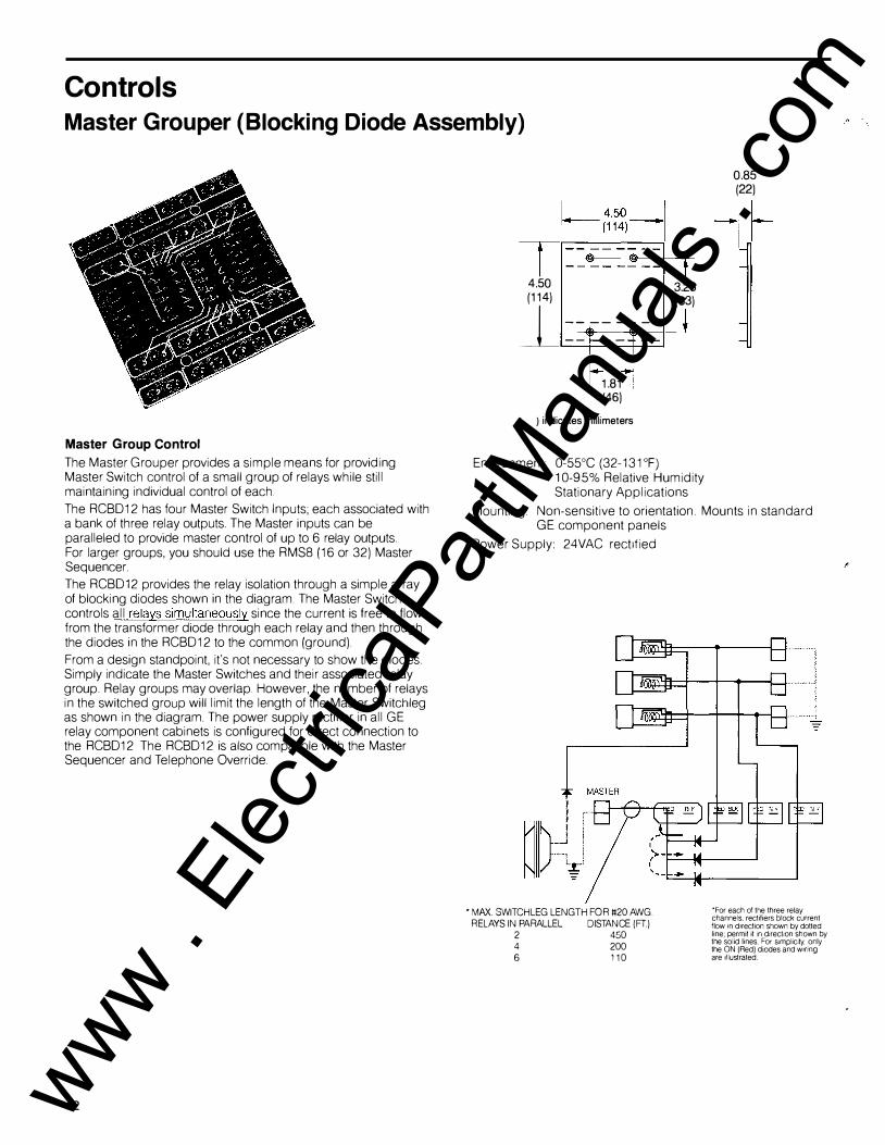
Controls Master Grouper (Blocking Diode Assembly)
Master Group Control
The Master Grouper provides a simple means for providing Master Switch control of a small group of relays while still maintaining individual control of each.
The RCBD12 has four Master Switch Inputs; each associated with a bank of three relay outputs. The Master inputs can be paralleled to provide master control of up to 6 relay outputs. For larger groups, you should use the RMS8 (16 or 32) Master Sequencer.
The RCBD 12 provides the relay isolation through a simple array of blocking diodes shown in the diagram. The Master Switch controls all relays simultaneously since the current is free to flow from the transformer diode through each relay and then through the diodes in the RCBD12 to the common (ground).
From a design standpoint, it's not necessary to show the diodes. Simply indicate the Master Switches and their associated relay group. Relay groups may overlap. However, the number of relays in the switched group will limit the length of the Master Switchleg as shown in the diagram. The power supply rectifier in all G E relay component cabinets is configured for direct connection to the RCBD12 The RCBD12 is also compatible with the Master Sequencer and Telephone Override.
1 2
4.50 (114)
1 4.5o _l - (114) 1
1_---------- -- --
1.81 (46)
) indicates millimeters
3.28 (83)
Environment: 0-55°C (32- 131 oF) 10-95% Relative Humidity Stationary Applications
0.85 (22)
-r-
Mounting Non-sensitive to orientation. Mounts in standard G E component panels
Power Supply: 24 VAC rectified
• MI\X. SWITCH LEG LENGTH FOR li20 AWG. RELAYS IN PARALLEL DISTANCE (FT)
2 450 4 200 6 1 1 0
*For each of the three relay channels, rectifiers block current flow 1n direction shown by dotted line; permit it 1n direction shown by the solid lines. �or Simplicity, .only the ON (Red( d1odes and w1nng are Illustrated
www . El
ectric
alPar
tMan
uals
. com

Master Sequencer
RMS8
I 4.50__j r-(114) �I
The Master Sequencer is a microprocessor controlled electronic switch with two independent inputs controlling 8, 16, or 32 relays ON and OFF. It provides three functions:
1. Master Group Control 2. Master Switchleg Extension 3. Maintained to Momentary Input Conversion
Master Group Control The RMS turns each of its associated relays O N or O F F one at a time when it detects a change of state on an input. For example, when the ON side of a master switch input is actuated, the RMS senses this action and provides a pulse to each of its O N output term inals in rapid succession (2-4 seconds) Since each relay output is pulsed individually, there is practically no limit to the number of relays that can be controlled as part of a master group while still maintaining individual switch control of each.
In addition, each output may drive up to three relays in parallel or drive the master input to an RCBD12 group of three relays.
Master Switchleg Extension The RMS does not have the same switchleg length limitation as the RCBD12. The master sw itchleg can be up to 1000 feet long regardless of the number of relays controlled.
Maintained to Momentary Input Conversion Each input channel on the RMS will accept e ither 3-w ire momentary contact switches, a single 3-wire maintained (form C) switch, or a s ingle 2-wire SPST switch. This allows it to interface directly with typical control devices such as timeclocks while still providing local master switch override.
Two Operating Modes ... ON/OFF or ON( OFF) only A mode jumper allows the RMS to be used as an " O N"/ " O F F" master controller or as an "ON" (" OFF") only device similar to the GE Motor Master.
"Two-Bank" .. . Mode Jumper Removed
ON/OFF MODE
Master Switch Type*
� ioM 3 WIRE MAINTAINED
9.50
(241)
l- 4.50-,
(114) I - -- -- -=fffli- -�_,_·4.=-+--� -
� · ·-· !i� -���--1]_
i 11= . 'lj-
RMS32 111=
) indicates millimeters
Master "A" Bank Switch Relay
Cat. No. Inputs Outputs
RMS8 2 8
RMS16 2 16 RSM32 2 32
I 1.72 I
1-(44) .[ ' I
"B" Bank Relay Outputs
8
16
32
Environment 0-55°C (32-131 ° F) 10-95% Relative Humid ity Stationary Applications
Mounting: Non-sensit ive to orientation. Mounts in standard GE component panels
Power Supply: 24VAC unrect if ied 2 watts
Master Action ........... Output Action Close "A" Contact Pulse "A" outputs Open "A" contact None Close "B" contact Pulse "B" outputs
In the ON/O FF mode, e ither master switch controls the relays both ON and O F F. The ON (red) relay control leads are connected to the "A" bank of outputs; the O F F (black) leads to the "B" bank. Up to 8 relays may be controlled independently by the RMSB ( 16 by the RMS 16; 32 by the RMS32).
[Sd=AandB Open "B" contact None
Close switch
Open switch
Pulse "A" outputs
Pulse "B" outputs
"One-Bank" .. . Mode Jumper Installed In the O N ( O F F) mode, actuating either master switch pulses both the "A" and "B" banks of relay outputs. Th is doubles the relay output capacity . For example, the RMSB w ill control up to 16 relays in the "One-Bank" mode.
The master switch action/RMS response for the two modes are summarized in the table to the r ight.
SPST
ON(OFF) ONLY MODE
Master Switch Type*
� �OM 3 WIRE MAINTAINED [Sd=AandB SPST
Master Action ........... Output Action Close "A" contact Pulse "A" then "B" outputs
Open "A" contact None
Close "B" contact Pulse "A" then "B" outputs
Open "B" contact None
Close switch
Open switch
Pulse "A" then "B" outputs
None
*WARNING: USE ISOLATED CONTACTS ONLY
13 www . El
ectric
alPar
tMan
uals
. com
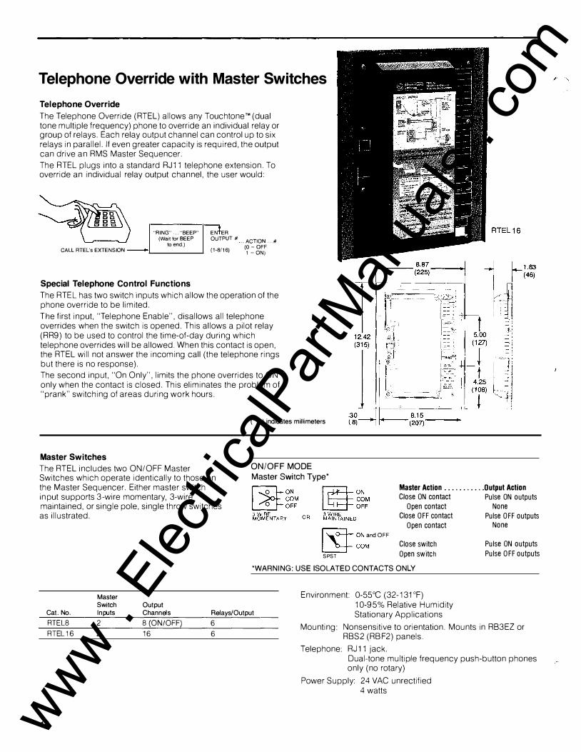
Telephone Override with Master Switches
Telephone Override
The Telephone Override ( RTEL) allows any Touchtone'" (dual tone multiple frequency) phone to override an individual relay or group of relays. Each relay output channel can control up to six relays in parallel. If even greater capacity is required, the output can drive an RMS Master Sequencer.
The R T EL plugs into a standard RJ11 telephone extension. To override an individual relay output channel, the user would:
CALL RTEL's EXTENSION
"RING" ... "BEEP" (Wait for BEEP to end.)
Special Telephone Control Functions
EN ER OUTPUT# .. ACTION ... # (1-8/16) (�: g��
The RT EL has two switch inputs which allow the operation of the phone override to be limited.
The first input, "Telephone Enable", disallows all telephone overrides when the switch is opened. This allows a pilot relay ( R R9) to be used to control the time-of-day during which telephone overrides will be allowed. When this contact is open, the RTEL will not answer the incoming call (the telephone rings but there is no response).
The second input, "On Only", limits the phone overrides to ON only when the contact is closed. This eliminates the problem of "prank" switching of areas during work hours.
( ) indicates millimeters
Master Switches
The RTEL includes two O N/ O F F Master Switches which operate identically to those on the Master Sequencer. Either master switch input supports 3-wire momentary, 3-wire maintained, or single pole, single throw switches as illustrated.
Master Switch Output
ON/OFF MODE Master Switch Type*
�ON and OFF
�COM SPST
Master Action ........... Output Action Close ON contact Pulse ON outputs
Open contact None Close OFF contact Pulse OFF outputs
Open contact None
Close switch
Open switch
Pulse ON outputs
Pulse OFF outputs
*WARNING: USE ISOLATED CONTACTS ONLY
Cat. No. Inputs Channels Relays/Output
Environment: 0-55°C (32-131 oF) 10-95% Relative Humidity Stationary Applications
RTEL8 2 8 (ON/OFF)
RTEL16 2 16
14
6
6 Mounting: Nonsensitive to orientation. Mounts in RB3EZ or
R BS2 ( R BF2) panels.
Telephone: RJ 11 jack. Dual-tone multiple frequency push-button phones only (no rotary)
Power Supply 24 VAC unrectified 4 watts
www . El
ectric
alPar
tMan
uals
. com

Photo Switches
BPHOT0-4 This unit is used to shed artificial lighting in interior daylit spaces. It monitors outside light levels through a perimeter window or skylight to provide the switching signal to the input of a Master Sequencer or Telephone Override. The photo switch will turn loads OFF when the exterior light level reaches the set footcandle level and remains there for 15 minutes. When the light level decreases to approximately 15% less than this setting and remains there for 15 minutes, loads will be turned O N. (See the wiring diagram on page 25.)
BPHOT0-5 This unit is designed to shed exterior lighting.
Specifications
Catalog Number
Foot Candle Range
Power Requirement .
Environment
RFI Environment ....
Immediate Response Feature ...
Hysteresis
BPHOT0- 4 (indoor use only) BPHOT0-5 (indoor/outdoor use)
BPHOT0- 4, 50-500 fc adjustable
BPHOT0-5 , 5-10 fc fixed
No external source needed
1 8 to 55° C (0 to 131 °F), non- corrosive atmosphere
0- 85% RH non-condensing (BPHOT0- 4)
0-100% RH (BPHOT0-5)
Less than 15 v/m
BPHOT0- 4 -Yes BPHOT0-5 - No
15% typ.@ 100 fc
20% typ. @ 300 fc 25% typ.@ 500 fc
15 www . El
ectric
alPar
tMan
uals
. com

Component Cabinets Large Cabinets
Low-Voltage Wiring The RB3EZ is designed for simple assembly of low voltage control components.
The color-coded, numbered low-voltage termination strips provide flexible push-on terminations for the relays and associated controls. An RA 16 rectifier is prewired to a solid brass bus-bar providing power to all relays. This integrated design approach simplies installation:
The steel barrier separating the high and low-voltage sections provides W' knockouts for up to 2 4 relays. The low-voltage section will accept any of the following combinations:
3 R MS8 ( 16) or 3 RCB D12 1 RMS8(16) or 1 RCBD12 and 1 R MS32 1 RTEL8( 16) and 1 R MS8(16) or 1 RCBD12
1. Plug the relay into the barrier and push its leads on to the color-coded terminations.
2. Parallel the Red/Black control leads to form relay groups as Available for surface or flush mounting. Gray enamel finish. Quick-turn cover screws. UL listed.
required. 3. Wire from the R MS or R T EL outputs to the relay groups.
Cat. No.
RB3EZ Description
Cabinet for 2 4 relays and associated controls. Includes RA 16 rectifier prewired to bus bar. Cover supplied separately.
4. Connect local switches to the relay terminations.
5. Connect Master Switches to the R MS or RTEL inputs.
Mounting
RB3-CFEZ Flush cover for RB3EZ The panel and all components are insensitive to mounting orientation. The panel would normally be mounted on either side of a lighting distribution panel. RB3- CSEZ Surface cover for RB3EZ
1 6
RB3EZ
One 112 x '14 K.O. This End----+-H
One 1 x 1'12 x 2 x 2'12 K.O. This End----*"
Note: Rush Cover dimensions are 19.62" X 29.59" ( 498) X (752)
) indicates millimeters
_i_____1 J Eight 112 K.OJ:'jide
I �0+00000001 f t f L------�+------__J· 1.00 1.12
2.06 2.00 (25) (28)-(52) (51) Two '12 x '14 K.O. This Side 1 One 112 K.O.
This End
2.38
� . (" 1 14.50 (368)
I 1 " L.:_2.38 �=i========1====':J...L(60)
I 4.91 18.25 4.91 I r125��---- (464) __
_ ..,...(125�
3.38 1- (86) I 1.42 -+-(36) 1.11 ----(28)
One V2 x 'I• K.O. '!*---+--This End
One V2 x '14 x 1 x 1 v. K.O. If--+--This End
2.06 (52)
18.12 (460)
One 1 x 1'12 x 2 x 2112 K.O. --This End
Two 1 x 1'12 x 2 x 21/2 K.O. '--------This Side
www . El
ectric
alPar
tMan
uals
. com

Small Cabinets
RBS 1
General Information
• Covers supp lied with cabinets • Listed by Underwriters' Laboratories, Inc.
• Accepts frames for relay mounting
Cat. No.
RBS 1
RBF 1
RBS 2
RBF 2
RBS 1
2.05 (52)
Description
Surface cab1net for one frame or two RMS8(16) or one RMS32 or two RCBD12
Same, flush
Surface cabinet for two frames or four RSM8(16) or 4 RCBD12 or two RMS32 , or one RTEL
Same, flush
Six'hK.O. Both Sides
Two V2 x % K.O. 1+-+--Both Sides
) indicates millimeters
Frames for Component Cabinets
RFT 1 78EZ
General Information
• Includes necessary low-voltage quick disconnect termina ls
• Serves as separator of low and high-voltage sections.
• Listed by Underwriters' Laboratories, Inc.
• For use with R BS 1, R BS 2, R B F 1 R BF 2 cabinets
Cat. No.
RRF 7 8 EZ
RFT 17 8 EZ
RFT 27 8EZ
Description
Frame to hold 1 to 6 relays
Frame with 11 8 VAC transformer* wired to RA 16 rectifier to hold 1 to 3 relays.
Frame with 277 VAC transformer* wired to RA 16 rectifier to hold 1 to 3 relays
*75VA momentary, 40VA continuous for 24 VAG systems (same characteristiCS as RT 1 and RT 2 pages 6 and 7).
RBS 2 1.00 (25)
_____ 12.03 ___
-1 J (306) :-.---------,-;- ,........---,
1 r� 12.00 (305) I
0 8 8 8 8 8
Six V2 K.O. Both Sides
Two V2 x '¥4 K.O. Both Sides
) indicates millimeters
1 7 www . El
ectric
alPar
tMan
uals
. com
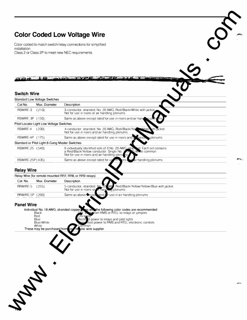
Color Coded Low Voltage Wire
Color coded to match sw itch/relay connections for simplified installation. Class 2 or Class 2 P to meet new N EC requirements.
Switch Wire Standard Low Voltage Switches
Cat No. Max. Diameter Description
RSWIRE-3 ( 2 10) 3-conductor, stranded, No. 20 AWG, Red/Black/White w1th Jacket Not for use 1n r1sers or a1r handling plenums.
RSWIRE-3P (.150) Same as above except rated for use in risers and a1r handl1ng plenums
Pilot/Locator Light Low Voltage Switches
RSWIRE-4 ( 230) 4-conductor, stranded, No. 20 AWG, Red/Black/Yellow/White w1th jacket Not for use 1n risers and a1r handling plenums
RSWIRE-4P (.17 5) Same as above except rated for use in nsers and a1r handling plenums
Standard or Pilot Light 8-Gang Master Switches
RSWIRE-25 (.540) 8 Individually Identified sets of 3 No. 20 AWG, stranded. Each set conta1ns a Red/Black/Yellow conductor. S1ngle No. 18 AWG Wh1te common Not for use in nsers and a1r handl1ng plenums.
RSWIRE-25P (.435) Same as above except rated for use in nsers and a1r handling plenums.
Relay Wire Relay Wire (for remote mounted RR7, RR8, or RR9 relays)
Cat No. Max. Diameter Description
RRWIRE-5 (.255) 5-conductor; stranded, No. 20 AWG, Red/Black/Yellow/Yellow/Blue w1th Jacket Not for use 1n risers or air handling plenums.
RRWIRE-5P ( 200) Same as above except rated for use 1n a1r handling plenums.
Panel Wire
1 8
Individual No. 1 8 AWG, stranded copper wires with the following color codes are recommended: Black OFF leads from RMS or RTEL to relays or Jumpers Red ON leads Blue Rectified power to relays and pilot lights Blue/Wh1te Unrect1fied power to RMS and RTEL electronic controls Wh1te Common
These may be purchased from your regular wire supplier.
a
www . El
ectric
alPar
tMan
uals
. com

Replacement Parts
Relays--------------
Relays for PAL Panels
PRR7L
Cat. No. Description
PRR7 L Similar to RR7 ( 8 ,9 )EZ except 13" leads
PRRBL
PRR9 L
Switches and Plates---------
Res Series
RFS/RKS Series
�� '?·· �. RFS 6
RKO
Frame with Switch. Switch purchased separately.
Cat. No. Description
Switches
RCS 2PL Pilot light, ivory
RCS 9 PL Pilot light, gray
Plates (302 Stainless, horizontal mount)
RP311 1 gang, 1 switch
RP312 1 gang, 2 switches
RP313 1 gang, 3 switches
RP324 2 gang, 4 switches
Cat. No. Description
Switches
RFS6 Unlighted, ivory
RKS6 Unlighted, key operated, ivory
RK 0 Key Plates (30 2 Stainless, horizontal mount)
RP211 1 gang, 1 switch
RP212 1 gang, 2 switches
RP213 1 gang, 3 switches
RP224 2 gang, 4 switches
Plates ( Ivory Urea, horizontal mount)
RP1 1 gang, 1 switch
RP2 1 gang, 2 switches
RP3 1 gang, 3 switches
RP24 2 gang, 4 switches
Surface Mounting Frame (Urea)
RA 13 Base and cover, ivory
Switches and Plates (cont.)
12 Position Master Switch
Cat. No.
RMS 4A
RP229
RA 12
RMS 4A RA 1 4
R A 12
Description
12- position master selector switch. Furnished with ivory plate.
Stainless steel plate for above.
Pilot light assembly for RMS 4A
Replacement pilot lamp
Controls---------------
Motor Masters*
RMS 5BL
Switch Interface*
1 master switch input, 25 ON relay outputs
Note: RMS8(1 6 ,32) provides direct substitute.
Cat. No.
RSI 2
Description
1 maintained, and one momentary ON /OFF master switch input; 3 ON /OFF relay outputs or 1 ON/OFF Motor Master output.
Note: RMS8 (16,32) provides functional substitute.
Blocking Diode Assembly*
RCBD 1
Cat. No.
RCBD 1
RA 20
Description
21 high capacity diodes with numbered termination strip Single replacement diode for RCBD.
Note: The RMS8(16 ,32) is recommended when grouping more than 5 relays. For large number of small groups, the Smart Remote Control panel is recommended.
*These items will be discontinued when the present stock is exhausted.
19 www . El
ectric
alPar
tMan
uals
. com

Basic Circuits and Applications Standard Low-Voltage Wiring Connecting Switches/Relays/Power Supply
Caution: Connecting relays in parallel is the same as connecting lamps in parallel. When so connected, they cannot be individual ly control led. See table on page 6 for the maximum number of relays that can be operated at one time with given transformer capacity.
Note: R R 8 and R R 9 pilot contacts are located internal to the relay. For the clarity of the wiring diagram only, these pilot contact symbols have been figuratively located externally adjacent to the relay. White wires shown in gray.
20
RT 1 OR RT 2 TRANSFORMER
RS 2-32 UNLIGHTED
SWITCH
LINE V� �,!V! 'RECTIFIER
24 V HALF-WAVE AC
RA 16 '------�1-----ll''--------1 LINE VOLTAGE
r
•
RS 2-32L LOCATOR SWITCH
RS 2-32P PI LOT SWITCH
RS 2-32
RS 2-32
24 V HALF-WAVE AC
LOAD
NOTE: One RFS 7 or RKS 7 old-style switch per relay or paralleled relay group maximum. This limitation does not apply to RS 2 series switches.
AUX CIRCUIT
LINE VOLTAGE
r LOAD
RR 8 SELF-ENERGIZING PILOT CONTACTS ( INTERNAL TO THE RELAY)
LINE VOLTAGE
r RR 9 ISOLATED PILOT CONTACTS (INTERNAL TO THE RELAY)
LINE VOLTAGE
r LOAD
LINE VOLTAGE
r LINE VOLTAGE
r
LINE VOLTAGE
r LOAD www .
Elec
tricalP
artM
anua
ls . c
om

Central/Local Switch Control of Relay s For master control of individual re lays on different f loors where separate floor transformers and switches are also used, this circuit diagram explains the necessary wiring requirements.
Note: White wires shown in gray.
LOAD ...J
TRANSFORMER
LINE VOLTAGE� D - RECTIFIER RA16
5th FLOOR RT 1 or RT 2
LOAD ...J
TRANSFORMER
LINE VOLTAGE� � - -RECTIFIER
RA16
1st FLOOR RT 1 or RT 2
2
KEY-OPERATED . . .. • cr'o 8 8 8
LOCK-OUT SWITCH D D D ON RMP 2-35
MASTER PLATE (CIRCUIT SHOWN OPEN)
BASEMENT
•
RMP 2-35 MASTER PLATE WITH EIGHT RS 2-32P
•
•
•
•
PILOT LIGHT SWITCHES (SWITCHES # 1 AND 5 SHOWN FULLY WIRED)
This circuit is especially useful for watchman lights controlled from watchman station, or for control of corridor lights from superintendent's office.
UNLIGHTED FLOOR
SWITCHES
UNLIGHTED FLOOR
SWITCHES
NOTE: Use of the key-operated lock-out switch on the master plate (to the OFF/OPEN position) will turn off all indicator lamps in the switches as well as prevent switching in the basement by unauthorized personnel. If maintained ' lighting of the indicator lamps is required, use individual key-operated switches (such as RS 2-32 PK) and do not use the master plate lock-out switch.
21 www . El
ectric
alPar
tMan
uals
. com

Pilot Light Status I nd ication for a G roup of Relays
Any Relay in Group "ON" Lights Pilot All Relays in Group "ON" to Light Pilot
tj * � tj * � • )1
•J1
• I I QJ I I QJ • I I QJ I I QJ
----•I
,
RECTIFIED 24VAC
*Pilot light contact is internal to relays. (For simplicity, red, blue, and black wires are not shown).
Switch Lockout The diagram illustrates suggested meth ods of l ocking out switches t o prevent unauth orized c ontr ol . The tw o individual sw itches at the left represent that part of the sw itch ing system n ot t o be locked out . The two ind ividual switches in the center can be l ocked out of contr ol with the single "lock-out" switch at the b ott om while the relays they n ormally c ontr ol can be
NO LOCKOUT
.J
22
LOCKOUT BY RR 9 RELAY OR
RMP 2-35 MASTER KEY
.J
INDIVIDUAL SWITCHES LOCKOUT BY RR 9 RELAY
operated fr om the master switch provided this is n ot l ocked out with its key switch. The two switches at the right are l ocked out al ong with the Master Station switches by the Master Stat ion lockout switch. Note : White w ires shown in gray.
LOCKOUT BY RMP 2-35 MASTER KEY
.J ...1
INDIVIDUAL SWITCHES
LOCKOUT SWITCH
www . El
ectric
alPar
tMan
uals
. com

M aster Control of G roup U s ing RCBD12 The RC B D12 provides economical switch ing of small groups of re lays wh i le maintaining individual cont rol of each. Simply connect the master switch to one of the four inputs and then connect the relays associated with it to the three o utputs. If there are more than 3 relays in the maste r gro up, you may paralle l the inputs as shown. Use the RMS8 (16 o r 32) for more than 6 relays in paralle l .
Selective Switching U s ing RCBD12 The diagram to the right shows how to obtain selective control over a gro up of re lays. The first maste r sw itch is wi red as the maste r to r both inputs 1 and 2, the second fo r 2 only. You can increase the number of "maste r levels " by s imply extend ing the wiring approach to more inputs.
Compatibility With Other Controls The RC B D 12 can be used in conjunction with an RMS Maste r Seq uencer or RT EL Te lephone Cont rol module. S imply connect an output of these devices to a master input on the RC B D12 to control a gro up of up to 3 re lays .
Selective Switching using Rectifiers This circuit shows how to obtain se lective cont rol over a g roup of lights. Assume the wi ring shown runs to a four-lamp fixtu re. Then :
• Switch #1 cont rols relay #1 and fi rst lamp. • Sw itch #2 controls re lay #1 and #2 and first two lamps. • Switch #3 cont rols al l th ree re lays and all fo ur lamps.
Switch #3, then, f unctions as a master cont rol device to r that fixture. Note pola rity of rectifie rs. Note: White wi res shown in g ray.
INDIVIDUAL SWITCHES
MAX. OF 3
TO ALL *BLUE RE:LAY BLUES��=++--W-1-+-.
� �r�"�LST..JER��--+-rf"',_""2"r'�l"')
'MAX SWITCHLEG LENGTH
FOR #20 AWG
RELAYS I N DISTANCE
PARALLEL (FT ) 2 450 4 200 6 1 1 0
SELECTIVE SWITCHING
MASTER OF 1 & 2
MASTER OF 2
No. 1
r- 3 -1 0 00 r- 4 -J D D D
No. 2 No. 3
WHIT I:
WHITE
WHITE
23 www . El
ectric
alPar
tMan
uals
. com

Simple Automation M aster Control of Group of Relays with Local Switch Override Th is circuit shows the wiring of an RMS 16 Master Sequencer to All of the applications illustrated for the Master Sequencer show provide master ON/OFF control of a group of relays while still it for ON/OFF operat ion (2-bank mode). For ON ( O F F) onl y allow ing ind ividual control o f each. Up to 3 relays may be operation, the mode jumper would be installed and only the connected in parallel on each RMS output (Again, connect ing ON ( O FF) relay leads would be connected to the outputs. In this relays in parallel means that they will always operate as a mode, an RMS 16 would drive 32 individual relays. group .)
MODE JUMPER REMOVED FOR ON & OFF OPERATION
PANEL MASTER SWITCH
TO RMS POWER INPUT
G lob al M aster Switch with Local Panel M asters The master sw itch inputs on Master Sequencers can be paralleled provided the supply transformers are wired to the same phase. The two independent master switch inputs on each RMS allow a local master sw itch to control each ind ividual RMS independent o f the other un its.
The master switches may also be wired for pilot indication using the R R S (any relay in group "ON" lights p ilot) or R R9 (all relays
GLOBAL MASTER SWITCH
24
*
RT 1 OR RT 2 TRANSFORMER
*Any output may also be connected to a Master Input ( 1-4) on the RCBD 1 2
in group "ON" t o light pilot) w iring illustrated o n page 22 . Another alternative is to allow a spare output on each RMS to drive an R R8 relay giving a pilot indicat ion o f the Master Sequencer 's operation. In this case, however, the pilot indicates the operation o f the RMS only; it doesn't reflect changes to indiv idual relays by the occupant sw itches.
'TRANSFORMERS MUST BE ON SAME PHASE. A SINGLE TRANSFORMER MAY ALSO BE USED.
www . El
ectric
alPar
tMan
uals
. com

Timeclock/B uild ing A utom ation System Control The master switch inputs on a Master Sequencer will als o accept the S PST or S P OT (form C) contacts typically pr ovided by a timeclock, electronic timeclock, or building automati on system. ((Use isolated contacts only!)
TIMECLOCK OR BUILDING AUTOMATION
D ayl ig hting Control In a typical daylighting application, a B P HOT0-4 photoswitch would monit or exterior light levels. Its switched c ontacts w ould drive the "daylighting" Master Sequencer t o shed/restore daylight circuits based on the amount of available daylight
The daylighting functi on is deactivated whenever the RR9 "Interl ock" relay is O F F. This stops the photoswitch from turning
WINDOW
BPHOT0-4 (Monitors Outside Light Level)
USE BPHOT0-5 FOR EXTERIOR LIGHTING
The circuit bel ow shows a timecl ock with single pole, single throw contacts used in lieu of the gl obal master switch to pr ovide automatic O N/ O F F operation f or the building. To pr ovide manual O N with multiple aut omatic O F F sweeps, the timecl ock would simply be wired t o the O F F(B) input only .
- MASTER SWITCH - ' 2 - A B COM A B COM
TO OTHER PANELS
ON the daylight circuits when the building is unoccupied. The l ocal occupant switch can always override the daylighting functi on for that particular area. Note : A timecl ock c ould replace the Panel Master Switch t o
provide a timed O F F for the exteri or lighting.
DAYLIGHT CIRCUITS
INTERLOCK RELAY
(CONTROLLED BY TIMECLOCK OR MASTER OVERRIDE. "ON" WHEN BUILDING IS OCCUPIED)
25 www . El
ectric
alPar
tMan
uals
. com

Telephone Override with M aster Switc h Control Telephone Override of Individual Relays
T he Telep hone Override (RTE L) allows existing Touc htone'" p hones to contro l individual relays. Eac h RTEL output can control up to six re lays in para l lel .
RJ11 TELEPHONE JACK (RTEL's EXTENSION #)
RTELS (16)
RTEL ON OFF
1
:�im l 8 -
ENABLE
SPECIAL FUNCTIONS ON ONLY
MASTER 1 - -SWITCHES 2 _-_
POWER 24 VAG
Master Switch Control . . . Global/Local Master Switches . . . Timeclock/ Building Automation
System Control . . . Daylighting
The RTEL includes two master switch inputs which operate identically to t he O N/ OFF master switc h inputs on t he Master Sequencer as illustrated below for t he global Timeclock function.
RJ11 TELEPHONE JACK (RTEL's EXTENSION #)
RTEL
TIMECLOCK
26
�ON�����f=Li====j 1 :::: :�:m \ �
SPECIAL
8 -
ENABLE
FUNCTIONS ON ONLY
POWER 24 VAG T
; (OPTIONAL LOCAL
SWITCH)
RTEL 1 ��=J ��::m ( � �
SPECIAL
8 - ENABLE
FUNCTIONS ON ONLY
RA 1 6
RJ11 TELEPHONE JACK (RTEL's EXTENSION #)
..__ __ P_ow_
E_R
_24_�_A
c_iT=-I=' �-�+ .. -... :::-.... -. ;:i]lt��""
www . El
ectric
alPar
tMan
uals
. com
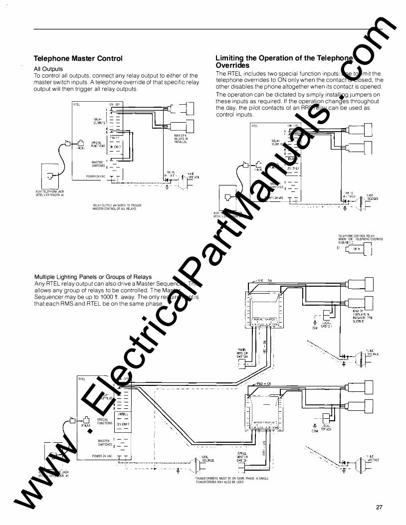
Telephone M aster Control
All Outputs To control all outputs, connect any relay output to e ither of the master switch inputs. A telephone override of that specific relay output will then trigger all relay outputs.
RJ11 TELEPHONE JACK (RTEL's EXTENSION #)
RTEL ON OFF
MASTER 1
MAX O F 6 RELAYS I N PARALLEL
SWITCHES 2 _-_ -
RA 1 6 .LINE POWER 24 VAC �
--=
------.--.-.-..-.--.--------:����f�tt=TAGE
RELAY OUTPUT #8 WIRED TO PROVIDE MASTER CONTROL OF ALL RELAYS
Multiple Lighting Panels or Groups of Relays Any RT EL relay output can a lso drive a Master Sequencer. This allows any group of relays to be controlled. The Master Sequencer may be up to 1000 ft away. The only requirement is that each RMS and RT EL be on the same phase.
RTEL
SPECIAL FUNCTIONS
MASTER 1 - -SWITCHES 2 _-_
POWER 24 VAG
L im it ing the Oper ation of the Telephone Overrides The RT EL includes two special function inputs: one to limit the telephone overrides to O N only when the contact is closed, the other d isables the phone altogether when its contact is opened.
The operation can be dictated by simply installing jumpers on these inputs as required. If the operation changes throughout the day, the pilot contacts of an R R9 relay can be used as control inputs.
RJ11 TELEPHONE JACK (RTEL's EXTENSION #)
RTEL
MASTER 1 - -SWITCHES 2 _-_
TELEPHONE CONTROL RELAY WHEN ''ON''. TELEPHONE OVERRIDE IS EN�
I I �
RJ11 TELEPHONE JACK (RTEL"s EXTENSION #)
"TRANSFORMERS MUST BE ON SAME PHASE. A SINGLE TRANSFORMER MAY ALSO BE USED
27 www . El
ectric
alPar
tMan
uals
. com

This diag ram illustrates a typical layout of an RB3EZ component TO LIGHTING LOADS cabinet and va rious comporoents wi red to circuit b reake rs and
external low-voltage switches.
4-CONDUCTOR WIRE e
8 e
WHITE VVIHt-BUS BAR
RS 2-32 P SWITCH
I
8 8 8 8 I
B B B B RMP 2-35 WITH
RS 2 SERIES SWITCHES
; C9
.lJ ' ' .J ' ' /
l I ! .=e: = = = = = = -
MASTER SW���H 'coM oM\
[""
r---
� � · I"" r. . I • I • I • • I • I • ��- I • • I= I • I= 1 : . I= I= I • I= 1 : . 1-
1 : I • • I • I • I • • I • I • I • • 1 : • • • • • •
� \,,� *
RB3EZ i COMPONENT CABINET P\ �
24 VOLT r--
TRANSFORMER RT 1 OR RT 2 \ I
RELAYS,
� CIRCUIT BRrKER PANEL
..\. h L � � I F �
� � I � ........... � .......... -I 0 ............
............ �
� 0 ............ 101!1 !!!!!!1 1 ............ � 0 � I -
............ 0 I �
_,--- 0 I �
0 � I ""'--
:;;;;!I a lJ � �us
BAR FOR BLUE WIRE
r. 1 : I • I • I • 1 :
l
�� WIRING TROUGH ----+
White wires shown in grey. Indicates Line Voltage Wiring Compartments
*Termination strip uses numbered, color-code 3/1s" push-on terminal strips. The multiple tabs are illustrated here as a single point for simplicity.
Simple Guideform Specification* Furnish and install complete remote control wiring system for control of lighting, receptacles and othe r e quipment as indicated on d rawings, diagrams and schedules. System shall be complete with t ransfo rme rs, rectifie rs, relays, switches, maste r-se lecto r switches, pilot lights, electronic cont rols, wa ll plates and wi ring. All remote-cont rol wi ring components shall be of same manufactu re and installed in acco rdance with the
*Consult you r GE rep resentative fo r a mo re complete specification.
28
recommendations of the manufactu rer. Remote-cont rol e quipment shall be as manufactured by Gene ral Electric Company o r of e qual quality, as app roved by the design enginee r.
Except whe re otherwise indicated, all such remote-cont rol wi ring shall be in acco rdance with Article 725, Class 2, of the National Electrical Code.
www . El
ectric
alPar
tMan
uals
. com

c
c
c
www . El
ectric
alPar
tMan
uals
. com

www . El
ectric
alPar
tMan
uals
. com