- epa02, epa04 and epa07 series 60r water pump ... · pdf file18sp663 – epa02, epa04 and...
TRANSCRIPT

18SP663 – EPA02, EPA04 and EPA07 Series 60® Water Pump Rear Cover Replacement Kit (P/N: 23538693)
KIT DESCRIPTION Water Pump Rear Cover Replacement Kit P/N: 23538693 is designed to address Series 60 water pumps that may prematurely start to leak from the rear covers. The new kit contains a new steel cover plate, O-ring seal and a chamfered snap ring. KIT CONTENTS The water pump rear cover replacement kit (P/N: 23538693) is for use on EPA02, EPA04 and EPA07 Series 60 engines. Listed in Table 1 are the kit parts:
Part No. Qty. Description 23538538 1 Rear Steel Cover 23538543 1 O-ring seal 23538605 1 Snap Ring 18SP663 1 Installation Instructions
Table 1 EPA02, EPA04 and EPA07 Series 60 Water Pump Rear Cover
Replacement Kit (P/N: 23538693) INSTALLATION PROCEDURE Use the following procedure to remove the currently installed water pump rear cover:
PERSONAL INJURY
To avoid injury, never remove any engine component while the engine is running.
18SP663 Page 1 of 6

PERSONAL INJURY
To avoid injury from accidental engine startup while servicing the engine, disconnect/disable the starting system.
1. Apply the parking brake, chock the wheels, disconnect vehicle battery power,
and perform any other applicable safety steps. 2. Remove the charge air cooler tube from the turbocharger to the cooler.
3. Drain the cooling system.
EYE INJURY
To avoid injury from flying parts when working with components under spring tension, wear adequate eye protection (face shield or safety goggles).
4. Remove the snap ring from the rear of the water pump using internal snap-ring pliers (Snap-On® PR7 or equivalent) with 90 degree tips. Discard the snap ring. See Figure 1.
1. Snap Ring 2. Water Pump Housing
Figure 1 Removing Snap Ring
18SP663 Page 2 of 6

5. Remove and discard the rear cover and O-ring seal from the water pump housing. See Figure 2.
1. O-ring Seal
Figure 2 Removing O-ring Seal and Water Pump Rear Cover NOTE:
To aid in the removal of the rear cover, use a sheet metal screw less than one inch long and screw it into the boss on the rear cover. Use a pry bar to aid in the removal of the cover. See Figure 2.
6. Carefully clean the snap ring groove on the water pump. Remove any rust and
debris from the groove. 7. Carefully remove any rust and debris in the location of the seal and rear cover
area.
18SP663 Page 3 of 6

Use the following procedure to install the new water pump rear cover:
1. Install the new O-ring seal (P/N: 23538543) into the water pump housing. If needed, use petroleum jelly to hold the O-ring seal in place prior to installing the rear cover. See Figure 3.
1. New O-ring Seal
Figure 3 Installing O-ring Seal into Water Pump Housing
2. Install the new steel water pump rear cover (P/N: 23538538). The stepped side
will face the water pump and the flat side faces the snap ring. See Figure 4.
Figure 4 Stepped Side of Water Pump Rear Cover
3. Install the new snap ring (P/N: 23538605), verifying that the chamfer of the snap ring is facing outwards. See Figure 5. Apply pressure to the middle of the water pump cover to aid in seating the snap ring. Verify that the snap ring is seated in the groove.
18SP663 Page 4 of 6
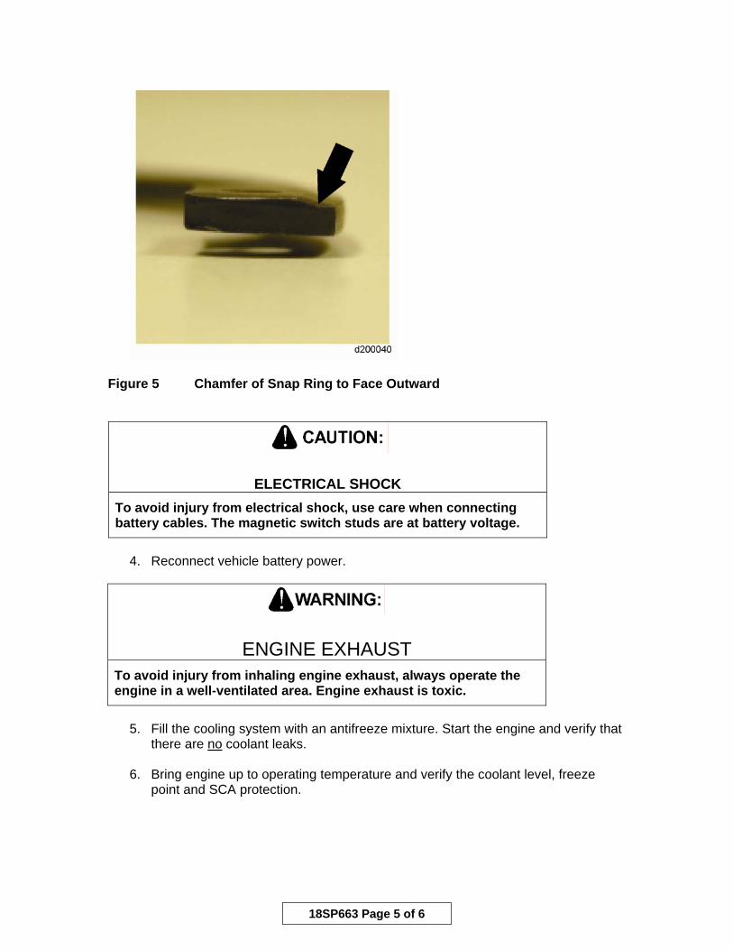
Figure 5 Chamfer of Snap Ring to Face Outward
ELECTRICAL SHOCK To avoid injury from electrical shock, use care when connecting battery cables. The magnetic switch studs are at battery voltage.
4. Reconnect vehicle battery power.
ENGINE EXHAUST
To avoid injury from inhaling engine exhaust, always operate the engine in a well-ventilated area. Engine exhaust is toxic.
5. Fill the cooling system with an antifreeze mixture. Start the engine and verify that
there are no coolant leaks.
6. Bring engine up to operating temperature and verify the coolant level, freeze point and SCA protection.
18SP663 Page 5 of 6

NOTICE: WARRANTY INFORMATION
A new Consolidated Labor Operation (CLO) #051002 was created for this repair. This CLO includes all steps to complete this repair. The primary failed part should be listed as P/N: 23537664.
Specifications are subject to change without notice. Detroit Diesel Corporation is registered to ISO 9001:2001. Copyright © 2008 Detroit Diesel Corporation. All rights reserved. Detroit Diesel Corporation is a Daimler company. 18SP663 0811 As technical advances continue, specifications will change. Printed in U.S.A.
18SP663 Page 6 of 6