, hamerton, i., & ivanov, d. (2017). positioning and ... · 510 ¸...
TRANSCRIPT
Ariu, G., Hamerton, I., & Ivanov, D. (2017). Positioning and aligning CNTsby external magnetic field to assist localised epoxy cure. Open Physics,14(1), 508-516. https://doi.org/10.1515/phys-2016-0057
Publisher's PDF, also known as Version of record
License (if available):CC BY-NC-ND
Link to published version (if available):10.1515/phys-2016-0057
Link to publication record in Explore Bristol ResearchPDF-document
This is the final published version of the article (version of record). It first appeared online via De Gruyter athttps://www.degruyter.com/view/j/phys.2016.14.issue-1/phys-2016-0057/phys-2016-0057.xml. Please refer toany applicable terms of use of the publisher.
University of Bristol - Explore Bristol ResearchGeneral rights
This document is made available in accordance with publisher policies. Please cite only the publishedversion using the reference above. Full terms of use are available: http://www.bristol.ac.uk/pure/user-guides/explore-bristol-research/ebr-terms/

© 2016 G. Ariu et al., published by De Gruyter Open.This work is licensed under the Creative Commons Attribution-NonCommercial-NoDerivs 3.0 License.
Open Phys. 2016; 14:508–516
Research Article Open Access
G. Ariu*, I. Hamerton, and D. Ivanov
Positioning and aligning CNTs by externalmagnetic field to assist localised epoxy cureDOI 10.1515/phys-2016-0057Received August 15, 2016; accepted November 23, 2016
Abstract: This work focuses on the generation of conduc-tive networks through the localised alignment of nanofillers, such as multi-walled carbon nanotubes (MWCNTs).The feasibility of alignment and positioning of function-alised MWCNTs by external DC magnetic fields was in-vestigated. The aim of this manipulation is to enhanceresin curing through AC induction heating due to hystere-sis losses from the nanotubes. Experimental analyses fo-cused on in-depth assessment of the nanotube functional-isation, processing and characterisation of magnetic, rhe-ological and cure kinetics properties of the MWCNT so-lution. The study has shown that an external magneticfield has great potential for positioning and alignment ofCNTs. The study demonstrated potential for creating well-ordered architectures with an unprecedented level of con-trol of network geometry. Magnetic characterisation indi-cated cobalt-plated nanotubes to be themost suitable can-didate for magnetic alignment due to their high magneticsensitivity. Epoxy/metal-plated CNT nanocomposite sys-temswere validated by thermal analysis as induction heat-ing mediums. The curing process could therefore be op-timised by the use of dielectric resins. This study offers afirst step towards the proof of concept of this technique asa novel repair technology.
Keywords: Multi-walled carbon nanotubes, high conduc-tivity connections, electroless plating, magnetic and ther-mal characterisation, rheological analysis
PACS: 61.46.Fg, 68.37.Lp, 81.07.-b, 81.07.De, 82.35.Np
*Corresponding Author: G. Ariu: Advanced Composite Centrefor Innovation and Science (ACCIS), University of Bristol, BS8 1TR,Bristol, UK, E-mail: [email protected]. Hamerton, D. Ivanov: Advanced Composite Centre for Innova-tion and Science (ACCIS), University of Bristol, BS8 1TR, Bristol,UK
1 IntroductionThe investigation of effective through-service re-manufacturing technologies for on-platform repair is ofgreat interest for aerospace applications. Examples of ad-vanced composite repairs for scarf and sandwich panelsare shown in Figure 1. However, the conventional method-ologies are labour intensive, and therefore costly and timeconsuming. They are also inefficient in terms of energydelivery in the course repair, suffer from non-uniform tem-perature distributions, and result in inconsistent levels ofcuring where part thicknesses are variable, all of whichultimately lead to compromised performance of the re-paired components. The present work explores a routetowards more controlled curing process. The researchfocuses on manipulation of nano fillers, such as multi-walled carbon nanotubes (MWCNTs), in host compositestructures exposed to external energy fields (specificallyelectromagnetic fields) for advanced curing purposes. Inthis regard, the replacement of a damaged composite part,using repair patches, is vital for the restoration of the orig-inal performance; this depends crucially on the networkgeneration at the bondline between the original structureand the replacement. The nanotube networks are knownto have great potential to improve the through-thicknessthermal conductivity (which is essential for uniformity oftemperature), and electrical conductivity (which is crit-ical for induction heating) of the composite laminates;these conductivities are low even in the case of carbonfibre composites, since the through-thickness propertiesare primarily determined by matrix performance. Previ-ous studies [1–3] have demonstrated the importance ofthe nano filler networks for several applications. Networkoptimisation would therefore help to accelerate the in-ternal heat supply, decrease temperature gradients alongthe bondline, evacuate heat upon cooling, and eventuallyavoid exothermic reactions.
The formation of conductive networks can be realisedthrough manipulation of magnetically sensitive nanofi-bres (MWCNTs) through external DC magnetic fields. Theobtained architecture of percolative nano-reinforcementsleads to increases in the local electrical and thermal con-
Brought to you by | University of BristolAuthenticated
Download Date | 3/8/17 4:30 PM

Positioning and aligning CNTs by external magnetic field to assist localised epoxy cure | 509
Figure 1: Advanced composite scarf (left) and sandwich panel (right)repair.
ductance. This is particularly important in the areaswherethere are connections between the host composite plies atthe bondline. A schematic is shown in Figure 2.
Figure 2: Schematic of composite inner structure for fibre alignmentby external energy fields.
Magnetic field manipulation of short fibres has al-ready been investigated in the literature [4–8]. The cur-rent project investigates the feasibility of using magneticfields for both alignments and induction-assisted heating.This is realised through the combination of magnetic fieldmanipulation before resin gelation under a direct current(DC) field, and induction heating via alternating current(AC) fields. The induction-heating phenomenon, widelyreported in the literature for different purposes [9–14], cantherefore be exploited in order to control the heat genera-tion across specific regions, such as the bondline. This canensure the most effective repair for structural purposes,with a faster, energy-efficient technique, as reported inthe literature for repair of aluminium components [15] andcomposite joints [16].
2 Experimental
2.1 Equipment
This study used: (a) equipment for functionalizing CNTsuch as a hot plate magnetic stirrer, sonicator and chem-ical reagents for the plating steps; (b) equipment forcharacterization of functionalised particles: TransmissionElectron Microscopy (TEM) and Scanning Electron Mi-croscopy (SEM) microscopy; (c) equipment for processing
the investigated nanocomposites: shear homogenizer IKAT10 basic ULTRA-TURRAX; (d) physical characterizationof the obtained metal functionalised CNT solutions: Dif-ferential Scanning Calorimetry (DSC), rheometry, Vibrat-ing Sample Magnetometer (VSM); (e) magnetic set-up foralignment and positioning of the CNT particles; (f) Com-puterised Tomography (CT) scans for characterisation ofthe alignment and positioning of the metal-plated CNTswithin a viscous medium.
The magnetic apparatus for generating DC fields isshown in Figure 3: there are 9800 turns in the mag-netic coils and the total electric current through the coilsreaches 1.5 A. The magnetic DC field (flux density of 0.5 T)was applied through two parallel square magnetic poles(pole edge size equal to 25.4mm). Thiswas used in order toalignmetal functionalised CNTswithin a viscousmedium.
Figure 3: DC magnetic apparatus.
Functionalised CNTs were characterized using Trans-mission Electron Microscopy (TEM) JEOL JEM-1400.Droplets of examined solutions were prepared from pow-dered nanotubes and subjected to an ultrasonic bath dis-persion in ethanol, prior to the TEM analysis. Rheolog-ical measurements were carried out using a cone/plateviscometer (Kinexus, Malvern). Samples containing 2.5wt.% and 5 wt.% (approximately 5 vol.% and 10 vol.%,respectively) of metal functionalised carbon nanotubesin PRIMETM 20LV (magnetically stirred plating step) wereprepared asmixed solutions immediately prior to the tests.These solutions were analysed under application of shearrates ranging from 0.1 s−1 to 100 s−1 (calculated automati-cally by the rheometer at the furthest gap location betweencone and plate, equal to 0.15 mm). Computerised tomog-raphy (CT) scans were carried out using a Nikon XTH225ST
Brought to you by | University of BristolAuthenticated
Download Date | 3/8/17 4:30 PM

510 | G. Ariu, I. Hamerton, and D. Ivanov
CT Scanner. This technique relies on the application ofX-rays for the 2D characterisation throughout the sampleand, ultimately, the combination of the 2D scans to obtainthe 3D samplemapping. Samples presented circular epoxyresin/MWCNT tabs with diameter of 35 mm and thicknessof 10 mm. These tests were carried out in order to assessthe CNT alignment within the epoxy resin following theexternally applied magnetic field and the related edgeeffects. Magnetic characterisation was performed usinga vibrating sample magnetometer (VSM), wherein sam-ples (solid or fluid), located between parallel pickup coils,were mechanically excited at a known frequency and si-multaneously subjected to a uniform DC field, rangingfrom −0.1 T to 0.1 T. The detection of the magnetic fieldlevel occurs using a Gauss meter placed on the magneticpoles of the apparatus [17]. Thermal characterisation wascarried out on samples (10-15 mg) in hermetically sealedpans using modulated differential scanning calorimetry(MDSC, TA Instruments Q200). Samples were equilibratedat the initial temperature of 20°C with a modulation of±1.00°C for 60 seconds, followed by a ramp rate of 5 K/minto reach the final temperature of 180°C.
2.2 Materials
Several carbon nanotube configuration were used in thisstudy:
1. Multi-wall carbon nanotubes (MWCNTs) (manufac-tured by Sigma Aldrich) were characterised by highaspect ratios (around 1500; cross-section diameterof 6-13 nm). Electroless plating of these carbon nan-otubes is described in the next paragraph.
2. Commercial nickel-coated nanotubes (manufac-tured by US Research Nanomaterials, Inc.) werepurchased. These CNTs exhibit purity higher than98%, outer diameters of 5-15 nm and aspect ratioshigher than 1000.
The low-viscosity host epoxy resin system wasPRIMETM 20LV (manufactured by Gurit) designed forliquid moulding processes. The epoxy comprises a slowamine hardener, has a viscosity of 1010-1070 cP at 20°C,and a cure schedule of 7 hours at 65°C as per supplier’sinstructions.
2.3 Electroless plating of multi-walledcarbon nanotubes
An electroless plating technique was used to deposit ho-mogeneous, chemically-stable, metal functionalised coat-ings (e.g. nickel, cobalt, and nickel-iron) on the sides andends of the MWCNTs [18, 19]. The procedure for Ni/Co de-position involved ananotube sensitization stepwith tin(II)chloride, an activation step involving palladium(II) chlo-ride, and a plating bath under sonication or magneticstirring forces. The latter required the use of a reducingagent (hypophosphite), a complexing agent (citrate) andthemetal salt to be reducedon to thenanotubesunder spe-cific pH and temperature conditions [20]. Nanotube aspectratio was significantly reduced during the sensitizationand activation steps which involved a sonication process.This phenomenon could therefore facilitate the final plat-ing step for the nanotube metal functionalization, whilstreducing nanotube bending and fracture during incorpo-ration within a host medium via sonication. A schematicof the electroless plating process is shown in Figure 4.
Figure 4: Schematic of electroless plating technique [19].
2.4 Blending of MWCNTs and alignment
The metal-functionalised MWCNTs were introduced intothe epoxy at a volume fraction of 2.5 wt.% within a circu-lar mould (outer diameter of 92 mm; thickness of 10 mm),and shear mixing (5000 rpm for 1 hour) was used to effectdispersion. The slowaminehardenerwas added to the sus-pension in order to facilitate the chemical crosslinking ofthe polymeric chains. The blends were then exposed to amagnetic DC field with flux density of 0.5 T, until gel timewas reached after around 200 minutes.
Brought to you by | University of BristolAuthenticated
Download Date | 3/8/17 4:30 PM

Positioning and aligning CNTs by external magnetic field to assist localised epoxy cure | 511
3 Results and discussion
3.1 Deposition of metal particles onMWCNTs
Several metal plating methodologies were investigated,including nickel, cobalt and nickel-iron plating. The aimof metal functionalisation was to increase the magneticsensitivity of the nanotubes. The functionalized MWC-NTs were characterized using TEM to investigate the po-sition and density of metal particles. Commercial nickel-coated nanotubes were compared to nickel-plated nan-otubes prepared experimentally in-house, to visually as-sess the integrity and the distribution of the nickel-coatingalong the length of the nanotubes. Nanotube micrographsfor the commercial nickel-coated and nickel-plated nan-otubes are shown in Figure 5; dark regions and spots inthe micrographs represent the metal nanoparticles on thewalls of the nanotubes. It is evident from Figure 5(a),that the heterogeneous nickel coating distribution reflectsthe poor adhesion of the coating, regardless of the coat-ing process. In contrast, Figure 5(b) shows more uniformwall coating distribution for single MWCNTs. Figure 5(c)shows the micrograph related to cobalt-plated MWCNTs.The latter were obtained through a magnetically stirredplating bath. Agglomeration greatly influences the nan-otube distribution. However, both nickel and cobalt seemto provide the nanotubes with satisfactory coating adhe-sion and uniform distribution, although to a lower extentfor the cobalt-plated nanotubes; this is potentially dueto the magnetic stirring process. Nanotube agglomerationrepresents awell-knownphenomenon,which is not neces-sarily detrimental to the overall component electrical per-formance [21].
3.2 Rheological characterization ofepoxy-MWCNT blends
Rheological measurements were carried out in order to in-vestigate the flow properties of themetal-plated CNT-filledresin systems. Plots of shear viscosity (in Pa·s) as a func-tion of the shear rate (in s−1) are shown in Figure 6 forCo30- and carboxyl-functionalised nanotubes embeddedin PRIMETM 20LV. Results are reported on a log-log plot.The introduction of MWCNTs in the epoxy resin causes apronounced increase in viscosity, leading to a viscosity dif-ference of about 200%between theneat resin and the solu-tions containingmetal-plated CNTs, as expected. The vari-ation in viscosity in the range of 2.5-5% weight fraction of
(a)
(b)
(c)
Figure 5: TEM comparison between commercial Ni-coated (a), Ni-plated (b), and Co-plated (c) MWNTs (please note different scaleson the micrographs). Ni-coated (a) nanotube diameter value wasobtained qualitatively via ImageJ software.
CNTs and different types of CNTs appears much smallerthan the drop in viscosity due to shear thinning at the ratesof 0.1-50 1/s. Therefore, the shear rate plays a significantrole in the shear viscosity changes; increasing shear rates
Brought to you by | University of BristolAuthenticated
Download Date | 3/8/17 4:30 PM

512 | G. Ariu, I. Hamerton, and D. Ivanov
could ease the processability of the nanotube-filled resinsystems due to shear-thinning effects.
The manipulation of the metal-plated nanotubeswithin epoxy resin under magnetic field was then inves-tigated for the generation of well-ordered networks for theincrease in local conductivity.
Figure 6: Shear viscosity as a function of shear rate for 5 vol.% and10 vol.% of COOH-MWCNTs and Co30-MWCNTs in PRIMETM 20LV.
3.3 Cure kinetics characterization of theepoxy-MWCNT blends
Preliminary MDSC analyses [22] were performed onnanocomposite systems with low-viscosity epoxy resinPRIMETM 20LV (plus amine hardener) containing 2.5 wt.%(approximately 5 vol.%) of metal functionalised MWCNTs.The total and reversingheat flowobtained couldhelp to as-sess the influence of the presence of nanotubes, and addedmetal functionality, on the thermal behaviour of the sys-tem. Figure 7 shows the preliminary total heat flow resultsfrom the analysis performed at a ramp rate of 5 K/min.
Neat resin results were considered as a baseline forthe assessment of thermal changes due to the presenceof the carbon nanotubes. An endothermic peak at 23°Ccould be observed: this was related to the nanotube dis-persion (bond breakage and macroscopic reorganisation)within the resin system, which requires an additional ex-ternal heat supply. However, the onset of the exothermicpeak, due the resin cure process, clearly showed a shifttowards lower temperatures for the metal-functionalisednanotubes. Moreover, the peak intensity increased for themetal-plated nanotubes. Therefore, the beneficial effect ofthe nanotubes to the cross-linking process can be stated,in particular for Ni-plated nanotubes. In this case, the ap-
Figure 7: Comparison of PRIMETM 20LV/amine/MWCNT (2.5 wt.%,approximately 5 vol.%) blend reactivity using MDSC (5 K/min.).
propriate balance of carboxyl functional groups andnickelnanoparticles leads to the highest compatibility and sta-bility with the host matrix, which is represented by thehigher exothermic heat value.
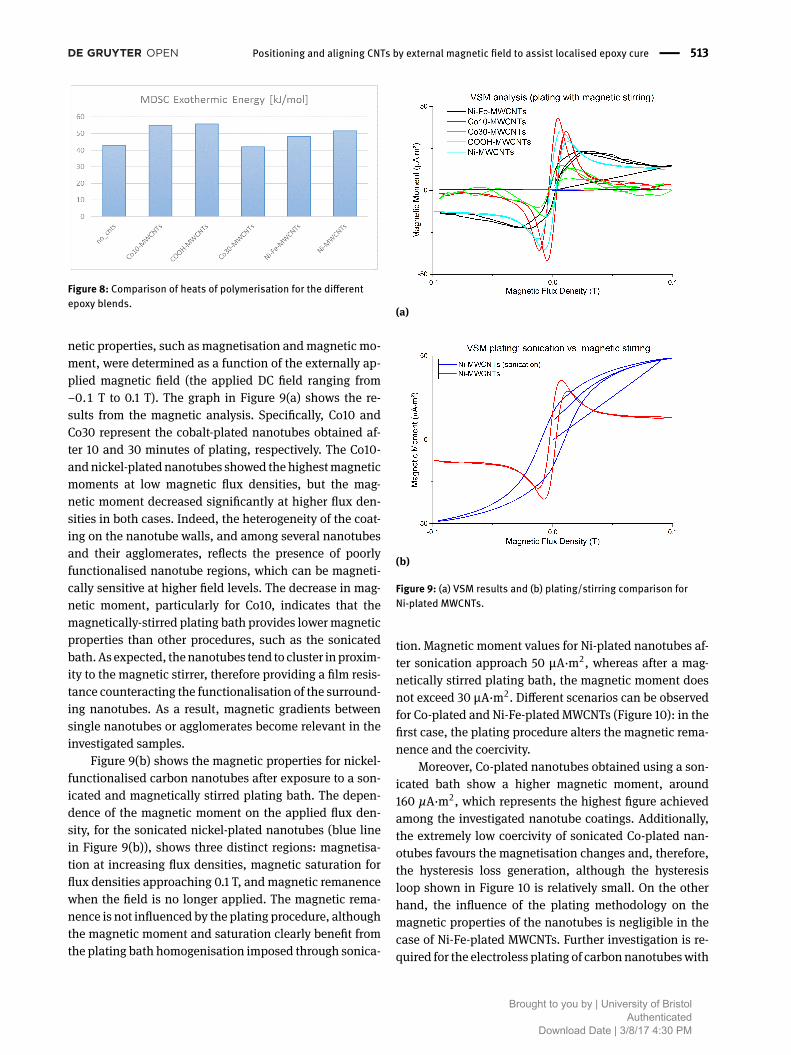
The introduction of metal-functionalised carbon nan-otubes clearly has an effect on the gelation and cross-linking process occurring in the resin. The exothermic en-ergies related to the MDSC curves are shown in Figure 8.These figures were obtained by taking into considerationboth the epoxy equivalent weight, and the amine equiv-alent weight, in the samples tested with MDSC. The in-troduction of MWCNTs in PRIMETM 20LV causes an in-crease in the exothermic heat generated during polymeri-sation compared to the neat resin. However, the carboxyl-functionalised nanotubes show the highest energy levels(around 55 kJ/mol), although the onset of the exother-mic peak appears at higher temperatures, compared to thecase of metal-plated nanotubes (except the Co10-platedCNTs; the ‘10’ represents the nanotubes were collected af-ter 10 minutes of cobalt plating). This could be relatedto the fact that metal nanoparticles on nanotubes accel-erate the creation of reactive regions with the polymericchains, but their chemical compatibility with the epoxyresin is lower than the compatibility between carboxylgroups and epoxy. Nonetheless, the introduction of metal-plated MWCNTs could be exploited for manipulating andoptimising the curing process during repairs.
3.4 Determining the magnetic susceptibilityof the blends
Metal-plated, carboxyl-functionalised MWCNTs as drypowder were characterised using VSM. Several key mag-
Brought to you by | University of BristolAuthenticated
Download Date | 3/8/17 4:30 PM
Positioning and aligning CNTs by external magnetic field to assist localised epoxy cure | 513
Figure 8: Comparison of heats of polymerisation for the differentepoxy blends.
netic properties, such as magnetisation andmagnetic mo-ment, were determined as a function of the externally ap-plied magnetic field (the applied DC field ranging from−0.1 T to 0.1 T). The graph in Figure 9(a) shows the re-sults from the magnetic analysis. Specifically, Co10 andCo30 represent the cobalt-plated nanotubes obtained af-ter 10 and 30 minutes of plating, respectively. The Co10-andnickel-plated nanotubes showed the highestmagneticmoments at low magnetic flux densities, but the mag-netic moment decreased significantly at higher flux den-sities in both cases. Indeed, the heterogeneity of the coat-ing on the nanotube walls, and among several nanotubesand their agglomerates, reflects the presence of poorlyfunctionalised nanotube regions, which can be magneti-cally sensitive at higher field levels. The decrease in mag-netic moment, particularly for Co10, indicates that themagnetically-stirred plating bath provides lowermagneticproperties than other procedures, such as the sonicatedbath.As expected, thenanotubes tend to cluster inproxim-ity to the magnetic stirrer, therefore providing a film resis-tance counteracting the functionalisation of the surround-ing nanotubes. As a result, magnetic gradients betweensingle nanotubes or agglomerates become relevant in theinvestigated samples.
Figure 9(b) shows the magnetic properties for nickel-functionalised carbon nanotubes after exposure to a son-icated and magnetically stirred plating bath. The depen-dence of the magnetic moment on the applied flux den-sity, for the sonicated nickel-plated nanotubes (blue linein Figure 9(b)), shows three distinct regions: magnetisa-tion at increasing flux densities, magnetic saturation forflux densities approaching 0.1 T, andmagnetic remanencewhen the field is no longer applied. The magnetic rema-nence is not influenced by the plating procedure, althoughthe magnetic moment and saturation clearly benefit fromthe plating bath homogenisation imposed through sonica-
(a)
(b)
Figure 9: (a) VSM results and (b) plating/stirring comparison forNi-plated MWCNTs.
tion. Magnetic moment values for Ni-plated nanotubes af-ter sonication approach 50 µA·m2, whereas after a mag-netically stirred plating bath, the magnetic moment doesnot exceed 30 µA·m2. Different scenarios can be observedfor Co-plated and Ni-Fe-plated MWCNTs (Figure 10): in thefirst case, the plating procedure alters the magnetic rema-nence and the coercivity.
Moreover, Co-plated nanotubes obtained using a son-icated bath show a higher magnetic moment, around160 µA·m2, which represents the highest figure achievedamong the investigated nanotube coatings. Additionally,the extremely low coercivity of sonicated Co-plated nan-otubes favours the magnetisation changes and, therefore,the hysteresis loss generation, although the hysteresisloop shown in Figure 10 is relatively small. On the otherhand, the influence of the plating methodology on themagnetic properties of the nanotubes is negligible in thecase of Ni-Fe-plated MWCNTs. Further investigation is re-quired for the electroless plating of carbonnanotubeswith
Brought to you by | University of BristolAuthenticated
Download Date | 3/8/17 4:30 PM

514 | G. Ariu, I. Hamerton, and D. Ivanov
Figure 10: Vibrating Sample Magnetometer plating/stirring compari-son for Co-plated MWCNTs.
metal compounds. The influence of the metal-plated nan-otubes on the flow properties of the matrix will be investi-gated in the next section as a means to assessing the pro-cessability of the system.
3.5 Magnetic alignment of the coated anduncoated MWCNTs
Initial work consisted of modelling analysis and experi-mental validation for the magnetic field manipulation ofnon-functionalised MWCNTs in low-viscosity epoxy resin,for alignment and network-generation purposes.Magneticequipment (Figure 3), was used for the through-thicknessnanotube alignment in the epoxy resin. Approximated val-ues of magnetic flux density for the alignment of uncoatednanotubes in PRIMETM 20LV were in the range of 0.5-0.7 T. This finding provided a guideline for the design of amagnetic DC setup used for further experimental analysis.The epoxy/MWCNT blends were exposed to a magnetic DCfield, with flux density of 0.5 T until gel time was reachedafter around 200 minutes.
Nickel-plated and carboxyl-functionalised MWCNTs,obtained through a sonicated plating bath, were intro-duced in low-viscosity epoxy resin (PRIMETM 20LV withamine hardener) with a weight fraction equal to 2.5 wt.%.The sample holder had an outer diameter of 35 mm andthickness of 10 mm. Both nanotube types were subjectedto an external magnetic field, with a flux density of 0.5 Tin the first instance. Consequently, further analysis in-volved the application of lower fields of 0.25 T and 0.1 T totwo samples, with 2.5 wt.% of nickel-plated nanotubes inPRIMETM 20LV, in order to investigate the nanotube mag-netic alignment at different field levels. The field was held
until gelation occurred. Sampleswere then allowed to coolnaturally to room temperature, in order to complete theresin cure. No external heat sources were applied duringthe field application, although the magnetic setup mayhave heated up, due to internal coil resistance, and ac-celerated the gelation process. Computerised tomography(CT) scans were carried out for those nickel-plated rein-forced epoxy systems subjected to flux densities of 0.25 Tand 0.5 T. Qualitative assessments of the preferential dis-tribution and through-thickness alignment of the nickel-plated and carboxyl-functionalised MWCNTs were con-ducted. Figure 11(a) shows the epoxy/nickel-plated nan-otube samples subjected to different magnetic field levels;the square alignment pattern can be observed. However, amore detailed CT analysis through is required.
(a)
(b)
Figure 11: (a) Ni-plated MWCNTs alignment comparison after DCfield and (b) CT scan of PRIMETM 20LV+2.5 wt.% Ni-plated MWCNTsunder 0.5 T.
Figure 11(b) shows the CT scan for nanocomposite sys-tems characterised by the presence of 2.5wt.%ofNi-platedMWCNTs inPRIMETM 20LV. The scanswere obtainedon thecured samples. The samples were first subjected to differ-ent DC fields, 0.25 T and 0.5 T, using the manufacturer’srecommended gel time. Subsequently, curing was carried
Brought to you by | University of BristolAuthenticated
Download Date | 3/8/17 4:30 PM

Positioning and aligning CNTs by external magnetic field to assist localised epoxy cure | 515
out at room temperature, and thenanotubes andnanotubeagglomerates can be observed distributed in a square pat-tern. The pattern reflects the magnetic pole geometry, andthe presence of edge effects. Themagnetic field reaches itshighest value at the edge of the magnetic poles, where themagnetic domains are not counterbalanced by adjacentneighbours, as in the magnetic bulk. Finite element anal-ysis was carried out using Finite Element Methods Mag-netics (FEMM) to replicate the magnetic field applicationthrough the thickness of the samples as shown inFigure 12.
The air gap between the poles, g, was equal to 28 mm,whereas the magnetic pole in-plane size, p, was 25.4 mm.The magnetic flux density mapping (Fig. 12) shows a gra-dient between the centre and the edges of the poles, fromyellow to purple respectively. Specifically, the increase inmagnetic flux density at the pole edges is around 40%compared to the pole centre, which leads to an inhomo-geneous magnetic field responsible for the alignment pat-tern. A more enhanced alignment pattern can be obtainedthrough the application of a stronger field, as expectedand shown in Figure 11. This phenomenon proves the po-tentialmanipulation ofmetal-functionalisednanotubes inlow-viscosity mediums (i.e. PRIMETM 20LV with additionof amine hardener) via external magnetic fields. Furtherinvestigation is required into nanotube manipulation inhigher viscosity systems, e.g. with the presence of struc-tural fibres in fibre-reinforced polymer composites.
Figure 12: Finite Element Methods Magnetics (FEMM) model show-ing the magnetic flux density gradient between the edges and cen-tre of the DC magnetic poles.
4 ConclusionsThe study has shown that an external magnetic field hasgreat potential for positioning and alignment of CNTs. Thestudy has demonstrated the feasibility of creating well-ordered architectures with an unprecedented level of con-trol of network geometry. Various methods of function-
alisation and various metal additives were considered.The microstructural and VSM analysis revealed that themost promising system was cobalt-functionalised nan-otubes obtained using the electroless plating technique.This methodology allows for a more uniform coating onthe nanotube walls than is currently obtained in commer-cially availablemetal-coated nanotubes. Magnetic charac-terisation indicated that cobalt-plated nanotubes showedthe highest magnetic moment (around 160 µA·m2) andlowest coercivity,making these themost suitable for align-ment, positioning and induction heating. Although intro-duced at volume fractions up to 5 wt.% (approximately10 vol.%), the metal-plated nanotubes did not hinder theresin processability, especially at relatively high shearrates, as shown from rheological measurements. There isa room for further optimization of metal coatings, andtheir influences on nanocomposite thermal and rheolog-ical properties. The potential use of these nanocompos-ite systems for induction heating purposes was validatedby thermal analysis. In particular, carboxyl-functionalisednanotubes showed the highest energy levels (around55 kJ/mol), which could be associated with the fact thatmetal nanoparticles on nanotubes accelerate the creationof reactive regions with the polymeric chains. However,their chemical compatibility with the epoxy resin waslower than the compatibility between carboxyl groups andepoxy. Nonetheless, this will be of great importance for anoptimised control of the curing process, supported by theuse of dielectric resins. This is study offers a first step to-wards proof of concept as a novel repair technology. Thiswill need to be applied tomore industrially relevant resins,which are generally of higher viscosity; the influence ofthemetal-platedMWCNTs on the thermal properties of theresin will be investigated further as a cure-control tool forhigh performance of the final part, especially at the bond-line. Alternative methods, such as fuzzy fibres [23], couldbe used to increase the through -thickness electrical con-ductivity, which can help create high-conductivity paths.
Acknowledgement: The authors would like to acknowl-edge support from Rolls-Royce plc, particularly Mr. PaulWilliams and Ms. Bhrami Jegatheeswaram Pillai, for thisresearch through the Composites University TechnologyCentre (UTC) at the University of Bristol, and from theEngineering and Physical Sciences Research Council (EP-SRC) through the Centre for Doctoral Training in Ad-vanced Composites at the University of Bristol (Grant no.EP/L016028/1). The authors would also like to acknowl-edge Dr. Jacopo Ciambella from the “Sapienza” Universityof Rome for the greatly appreciated technical support atthe start of the project.
Brought to you by | University of BristolAuthenticated
Download Date | 3/8/17 4:30 PM

516 | G. Ariu, I. Hamerton, and D. Ivanov
References[1] Yan, X. et al. (2016) Lowly loaded carbon nanotubes induced
high electrical conductivity and giant magnetoresistance inethylene/1-octene copolymers. Polymer. 103: 315-327.
[2] Wu, K. et al. (2016) Largely enhanced thermal and electricalconductivity via constructing double percolated filler networkin polypropylene/expanded graphite - Multi-wall carbon nan-otubes ternary composites. Composites Science and Technol-ogy. 130: 28-35.
[3] Lian, G. et al. (2016) Vertically Aligned and InterconnectedGraphene Networks for High Thermal Conductivity of EpoxyComposites with Ultralow Loading. Chemistry of Materials. 28:6096-6104.
[4] Kimura, T. et al. (2002) Polymer Composites of Carbon Nan-otubesAlignedbyaMagnetic Field. AdvancedMaterials. 14 (19):1380-1383.
[5] Erb, R. M. et al. (2012) Composites reinforced in three dimen-sions by using low magnetic fields. Science. 335(13): 199-204.
[6] Choi, E. S. et al. (2003) Enhancement of thermal and electri-cal properties of carbon nanotube polymer composites by mag-netic field processing. Journal of Applied Physics. 94(9): 6034-6039.
[7] Goc, K. et al. (2016) Influence of magnetic field-aided filler ori-entation on structure and transport properties of ferrite filledcomposites. Journal ofMagnetismandMagneticMaterials. 419:345–353.
[8] Le Ferrand, H. et al. (2016) Magnetic assembly of transparentand conducting graphene-based functional composites. NatureCommunications. 7: 1-9.
[9] Mas, B. et al. (2013) Thermoset curing through Joule heating ofnanocarbons for composite manufacture, repair and soldering.Carbon. 63: 523–529.
[10] Bayerl, T. et al. (2014) The heating of polymer composites byelectromagnetic induction - A review. Composites Part A: Ap-plied Science and Manufacturing. 57: 27–40.
[11] El-Tantawy, F. et al. (2003) A novel way of enhancing the elec-trical and thermal stability of conductive epoxy resin–carbonblack composites via the Joule heating effect for heating-element applications. Journal of Applied Polymer Science. 87:97-109.
[12] Fink, B. K. et al. (1992) A Local Theory of Heating in Cross-PlyCarbon Fiber Thermoplastic Composites byMagnetic Induction.Polymer Engineering & Science. 32: 357–369.
[13] Yarlagadda, S. et al. (2002) A study on the induction heating ofconductive fiber reinforced composites. Advanced CompositeMaterials. 11(1): 71-80.
[14] Abliz, D. et al. (2013) Curing Methods for Advanced PolymerComposites - A Review. Polymers & Polymer Composites. 21(6):341-348.
[15] Kim, M. et al. (2014) Repair of aircraft structures using compos-ite patches bonded through induction heating. Advanced Com-posite Materials. 24(4): 307-323.
[16] Mahdi, S. et al. (2003) A Comparison of Oven-cured andInduction-cured Adhesively Bonded Composite Joints. Journalof Composite Materials. 37(6): 519-541.
[17] Foner, S. (1996) The vibrating sample magnetometer: Experi-ences of a volunteer (invited). Journal of Applied Physics. 79(8):4740-4745.
[18] Grzelczak, M. et al. (2007) Pt-Catalyzed Formation of NiNanoshells on CarbonNanotubes. Angewandte Chemie Interna-tional Edition. 46: 7156-7160.
[19] Sun, Y.-P. et al. (2002) Functionalized Carbon Nanotubes: Prop-erties and Applications. Accounts of Chemical Research. 35:1096-1104.
[20] Li, Q. et al. (1997) Coating of Carbon Nanotube with Nickelby Electroless Plating Method. Japanese Journal of AppliedPhysics. 36 (2): 501-503.
[21] Seidel, G. D. et al. (2008) Analysis of Clustering and Inter-phase Region Effects on the Electrical Conductivity of Car-bon Nanotube-Polymer Nanocomposites via Computational Mi-cromechanics. ASME Proceedings |Multifunctional Materials:159-165.
[22] Ozawa, T. (2000) Thermal analysis— review and prospect. Ther-mochimica Acta. 355(1-2): 35-42.
[23] Pozegic, T. R. et al. (2014) Low temperature growth of carbonnanotubes on carbon fibre to create a highly networked fuzzyfibre reinforced composite with superior electrical conductivity.Carbon. 74: 319-328.
Brought to you by | University of BristolAuthenticated
Download Date | 3/8/17 4:30 PM