++ hydraulic gear pumps - universal hydraulics ltd · d100-001 id02 3 formula features construction...
TRANSCRIPT

++
Edition: 03/05.2013F 03 T A Replaces: F 02 T A
Headquarters:
CASAPPA S.p.A.Via Balestrieri, 1
43044 Lemignano di Collecchio
Parma (Italy)
Tel. (+39) 0521 30 41 11
Fax (+39) 0521 80 46 00
IP VideoconferencingE-mail: [email protected]
HYDRAULIC GEAR PUMPS

2 ID02 D100-001
Formula
INDEX
FEATURES
1 Mounting flange2 Seals3 Gear4 Body5 Thrust plates6 Shaft7 Outboard bearing
Modi!cation from former edition.
Section Description Page
FEATURES 2
SINGLE GEAR PUMPS
PERFORMANCE CURVES 9
FP 20 18
FP 30 23
FP 40 31
MULTIPLE GEAR PUMPS 37
PORTS CONNECTORSTIGHTENING TORQUE 65
SUPPORT
SUPPORT (ISO STANDARD) 66
KIT TO ASSEMBLE FORMULA PUMPS WITH SUPPORT 67
APPLICATIONS 68
CHANGING ROTATION 70
INSTRUCTIONS 71
FORMULA designates a CASAPPA gear pump range specifically designed for applications requiring high pressure levels also at low speed; applications such as truck-mounted cranes, tripper trucks and lift-trucks etc. Special design features and an exclusive CASAPPA patent have perfected a sophisticated mechanism which makes FORMULA a highly reliable unit, proven by years of service in the specific field of use. The versatility offered by the range of Italian (triangular) European (ISO) and American (SAE) mounting flanges allows to the FORMULA pumps to be used in several applications.
DISPLACEMENTSFrom 0.50 in3/rev (8,26 cm3/rev)To 9.20 in3/rev (150,79 cm3/rev)
PRESSUREMax. continuous 4205 psi (290 bar)Max. intermittent 4568 psi (315 bar)Max. di peak 4713 psi (325 bar)
MAX. SPEEDMax. 3000 min-1
�z Two piece cast iron housing
�z High performance at very low speed
�z Ideal for truck applications
O 0
3/05
.201
3R
epla
ces:
01/
08.2
005
O

D100-001 ID02 3
Formula
FEATURES
Construction External gear type pumps
Mounting ISO (ZF), ITALIAN (triangular) and SAE flanges
Line connections Screw
Direction of rotation (looking at the drive shaft) Anti-clock (S) - clockwise (D) - reversible (R or B)
Inlet pressure range for pumps 10 ÷ 44 psi - [0,7 ÷ +3 bar (abs.)]
Fluid temperature range See table (1)
FluidMineral oil based hydraulic fluids to ISO/DIN and fire resistant fluids [see table (1)]. For other fluids please consult our technical sales department.
Viscosity range From 60 to 456 SSU [12 to 100 mm2/s (cSt)] recommended Up to 3410 SSU [750 mm2/s (cSt)] permitted
Filtering requirement See table (2)
Antioxidant protection Red paint IC105
Tab. 2Working pressure psi (bar)
∆p<2030 (140)
2030<∆p<3045 (140) (210)
∆p>3045 (210)
Contamination class NAS 1638 10 9 8
Contamination class ISO 4406:1999 21/19/16 20/18/15 19/17/14
Achieved with filter ß10 (c) ≥ 200 according to ISO 16889 _ 10 μm 10 μm
Achieved with filter ß25 (c) ≥ 200 according to ISO 16889 25 μm _ _
Tab. 1
Type Fluid compositionMax
pressurepsi - (bar)
Maxspeedmin-1
Temperature °F - (°C)Seals (�)Min Max
continuousMaxpeak
ISO/DIN Mineral oil based hydraulicfluid to ISO/DIN See page 5 - 6 - 7 See page 5 - 6 - 7
-13 (-25) 176 (80) 212 (100) N
-13 (-25) 230 (110) 257 (125) V
HFAOil emulsion in water
5 ÷ 15% of oil725 (50) 1500 36 (2) 131 (55) _ N
HFB Water emulsion in oil40 % of water 1740 (120) 1500 36 (2) 140 (60) _ N
HFC Water - glycol 1450 (100) 1500 -4 (-20) 140 (60) _ N Bz
HFD Phosphate ester (z) 2175 (150) 1500 14 (-10) 176 (80) _ V Bz
(�) N = Buna N (standard) - V= Viton - N Bz= Buna N and Bronze thrust plates - V Bz=Viton and Bronze thrust plates. (z) For skydrol phosphate esters please consult our technical sales department.
Casappa recommends to use its own production filters:
O
WARNING !Failure or improper use of the product can cause damage at the same product or system.
Make sure that this is the last issue.
Rep
lace
s: 0
2/07
.200
8O
03/
05.2
013

Formula
4 ID02 D100-001
FEATURES
PRESSURE DEFINITION
p1 Max. continuous pressurep2 Max. intermittent pressurep3 Max. peak pressure
GENERAL NOTES
Available with different inlet and outlet ports. Standard pumps are equipped with BUNA N (N) seals, for particular operating conditions (V) VITON seals and BUNA or VITON seals with bronze thrust plates (N Bz), (V Bz) are availa-ble. If you use fire resistant fluids specify the type of them at the order.For more information please consult our technical sales department.
Max. 20 s Max. 8 s
p [bar] - [(psi)]
t [s]
p
1
p
2
p
3
DEFINITION OF ROTATION DIRECTION LOOKING AT THE DRIVE SHAFT
ANT-CLOCK ROTATION CLOCKWISE ROTATION REVERSIBLE ROTATION
01/0
8.20
05
Formula
D100-001 ID02 5
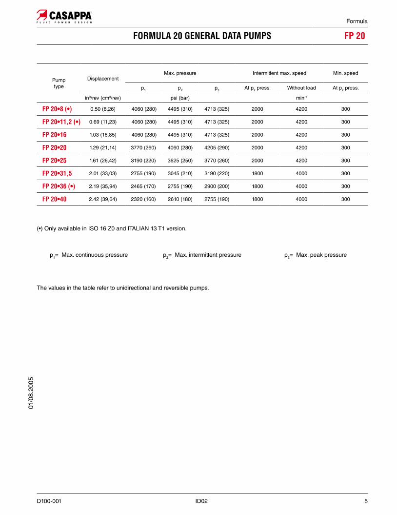
FORMULA 20 GENERAL DATA PUMPS FP 20
Pumptype
DisplacementMax. pressure Intermittent max. speed Min. speed
p1 p2 p3 At p2 press. Without load At p2 press.
in3/rev (cm3/rev) psi (bar) min-1
0.50 (8,26) 4060 (280) 4495 (310) 4713 (325) 2000 4200 300
0.69 (11,23) 4060 (280) 4495 (310) 4713 (325) 2000 4200 300
1.03 (16,85) 4060 (280) 4495 (310) 4713 (325) 2000 4200 300
1.29 (21,14) 3770 (260) 4060 (280) 4205 (290) 2000 4200 300
1.61 (26,42) 3190 (220) 3625 (250) 3770 (260) 2000 4200 300
2.01 (33,03) 2755 (190) 3045 (210) 3190 (220) 1800 4000 300
2.19 (35,94) 2465 (170) 2755 (190) 2900 (200) 1800 4000 300
2.42 (39,64) 2320 (160) 2610 (180) 2755 (190) 1800 4000 300
p1= Max. continuous pressure p2= Max. intermittent pressure p3= Max. peak pressure
The values in the table refer to unidirectional and reversible pumps.
( Only available in ISO 16 Z0 and ITALIAN 13 T1 version.
01/0
8.20
05
Formula
6 ID02 D100-001
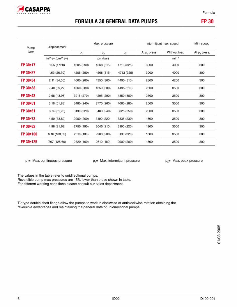
Pumptype
DisplacementMax. pressure Intermittent max. speed Min. speed
p1 p2 p3 At p2 press. Without load At p2 press.
in3/rev (cm3/rev) psi (bar) min-1
1.05 (17,28) 4205 (290) 4568 (315) 4713 (325) 3000 4000 300
1.63 (26,70) 4205 (290) 4568 (315) 4713 (325) 3000 4000 300
2.11 (34,56) 4060 (280) 4350 (300) 4495 (310) 2800 4200 300
2.40 (39,27) 4060 (280) 4350 (300) 4495 (310) 2800 3500 300
2.68 (43,98) 3915 (270) 4205 (290) 4350 (300) 2500 3500 300
3.16 (51,83) 3480 (240) 3770 (260) 4060 (280) 2500 3500 300
3.74 (61,26) 3190 (220) 3480 (240) 3625 (250) 2000 3500 300
4.50 (73,82) 2900 (200) 3190 (220) 3335 (230) 1800 3500 300
4.98 (81,68) 2755 (190) 3045 (210) 3190 (220) 1800 3500 300
6.16 (100,52) 2610 (180) 2900 (200) 3190 (220) 1800 3500 300
7.67 (125,66) 2320 (160) 2610 (180) 2900 (200) 1800 3500 300
The values in the table refer to unidirectional pumps.Reversible pump max pressures are 15% lower than those shown in table.For different working conditions please consult our sales department.
T2 type double shaft flange allow the pumps to work in clockwise or anticlockwise rotation obtaining the reversible advantages and maintaining the general data of unidirectional pumps.
01/0
8.20
05
p1= Max. continuous pressure p2= Max. intermittent pressure p3= Max. peak pressure

Formula
D100-001 ID02 7
Pumptype
DisplacementMax. pressure Intermittent max. speed Min. speed
p1 p2 p3 At p2 press. Without load At p2 press.
in3/rev (cm3/rev) psi (bar) min-1
3.75 (61,43) 4205 (290) 4568 (315) 4713 (325) 2700 4200 300
4.43 (72,60) 4060 (280) 4350 (300) 4568 (315) 2700 4200 300
5.28 (86,56) 3770 (260) 4060 (280) 4205 (290) 2700 4000 300
6.64 (108,90) 3480 (240) 3770 (260) 4060 (280) 2700 4000 300
8.18 (134,03) 3190 (220) 3625 (250) 3770 (260) 2500 4000 300
9.20 (150,79) 2610 (180) 3045 (210) 3190 (220) 2500 4000 300
The values in the table refer to unidirectional pumps.Reversible pump max pressures are 15% lower than those shown in table.For different working conditions please consult our sales department.
T2 type double shaft flange allow the pumps to work in clockwise or anticlockwise rotation obtaining the reversible advantages and maintaining the general data of unidirectional pumps.
01/0
8.20
05
p1= Max. continuous pressure p2= Max. intermittent pressure p3= Max. peak pressure

Formula
8 ID02 D100-001
DESIGN CALCULATIONS FOR PUMPS
Q US gpm (l/min) Flow
M lbf in(Nm) Torque
P HP (kW) Power
V in3/rev (cm3/rev) Displacement
n min-1 Speed
"p psi (bar) Pressure
Șv= Șv (V, ∆p, n) (≈ 0,98) Volumetric efficiency
Șhm= Șhm (V, ∆p, n) (≈ 0,90) Mechanical efficiency
Șt = Șv Șhm (≈ 0,88) Overall efficiency
Note: Diagrams providing approximate selection data will be found on subsequent pages.
O 0
3/05
.201
3R
epla
ces:
01/
08.2
005
Q = Q theor. Șv
[l/min]Qtheor. =
V (cm3 -1)
1000
M =M teor.
[Nm]Șhm
Mtheor. =3/rev)
62,83
PIN =P OUT
[kW] Șt
POUT = 600
O

D100-001 ID02 9
Formula
FORMULA 20 GEAR PUMPS PERFORMANCE CURVES FP 20
Each curve has been obtained at 122 °F (50°C), using oil with viscosity 168 SSU (36 cSt) at 104 °F (40°C) and at these pres-sures:
FP 20
290 psi (20 bar)4060 psi (280 bar)290psi (20 bar)4060 psi (280 bar)290 psi (20 bar)4060 psi (280 bar)290 psi (20 bar)3770 psi (260 bar)290 psi (20 bar)3190 psi (220 bar)290 psi (20 bar)2755 psi (190 bar)290 psi (20 bar)2465 psi (170 bar)290 psi (20 bar)2320 psi (160 bar)
O
Rep
lace
s: 0
1/08
.200
5O
03/
05.2
013

10 ID02 D100-001
Formula
FORMULA 20 GEAR PUMPS PERFORMANCE CURVES FP 20
01/0
8.20
05

D100-001 ID02 11
Formula
FORMULA 20 GEAR PUMPS PERFORMANCE CURVES FP 2001
/08.
2005

12 ID02 D100-001
Formula
290 psi (20 bar)4205 psi (290 bar)290 psi (20 bar)4205 psi (290 bar)290 psi (20 bar)4060 psi (280 bar)290 psi (20 bar)4060 psi (280 bar)290 psi (20 bar)3915 psi (270 bar)290 psi (20 bar)3480 psi (240 bar)290 psi (20 bar)3190 psi (220 bar)290 psi (20 bar)2900 psi (200 bar)290 psi (20 bar)2755 psi (190 bar)290 psi (20 bar) 2610 psi (180 bar)290 psi (20 bar)2320 psi (160 bar)
O
Each curve has been obtained at 122 °F (50°C), using oil with viscosity 168 SSU (36 cSt) at 104 °F (40°C) and at these pres-sures:
O 0
3/05
.201
3R
epla
ces:
01/
08.2
005

D100-001 ID02 13
Formula
01/0
8.20
05

14 ID02 D100-001
Formula
01/0
8.20
05

D100-001 ID02 15
Formula
01/0
8.20
05

16 ID02 D100-001
Formula
290 psi (20 bar)4205 psi (290 bar)290 psi (20 bar)4060 psi (280 bar)290 psi (20 bar)3770 psi (260 bar)290 psi (20 bar)3480 psi (240 bar)290 psi (20 bar)3190 psi (220 bar)290 psi (20 bar)2610 psi (180 bar)
O
Each curve has been obtained at 122 °F (50°C), using oil with viscosity 168 SSU (36 cSt) at 104 °F (40°C) and at these pres-sures:
O 0
3/05
.201
3R
epla
ces:
01/
08.2
005

D100-001 ID02 17
Formula
01/0
8.20
05

Formula
18 ID02 D100-001
FORMULA 20 HYDRAULIC GEAR PUMPS ISO STANDARD
GAS STRAIGHT THREAD PORTSBritish standard pipe parallel (55°) conforms to UNI - ISO 228
Pump typeA B C Mass
mm (in) mm (in) kg (lbs)
104 (4.094) 80 (3.150)
G 1/2
5,31 (11.71)
107,5 (4.232) 83,5 (3.287) 5,70 (12.57)
117 (4.606) 87,5 (3.445) 6,00 (13.23)
123,5 (4.862) 94 (3.701) 6,35 (14.00)
131,5 (5.177) 87 (3.425)
G 3/4
6,80 (14.99)
141,5 (5.571) 97 (3.819) 7,18 (15.83)
146,4 (5.764) 91,4 (3.598) 7,44 (16.41)
151,5 (5.965) 97 (3.819) 7,80 (17.20)
How to order:
Radial and/or axial load are not allowed.
Standard version pumps have reversible rotation and internal drain.
The drawing shows the version with rear ports.Removing the lateral plugs all possible combination ports are allowed.
Screw tightening torque Nm (lbf in)
V70 ±7 (558 ÷ 682)
01/0
8.20
05

Formula
D100-001 ID02 19
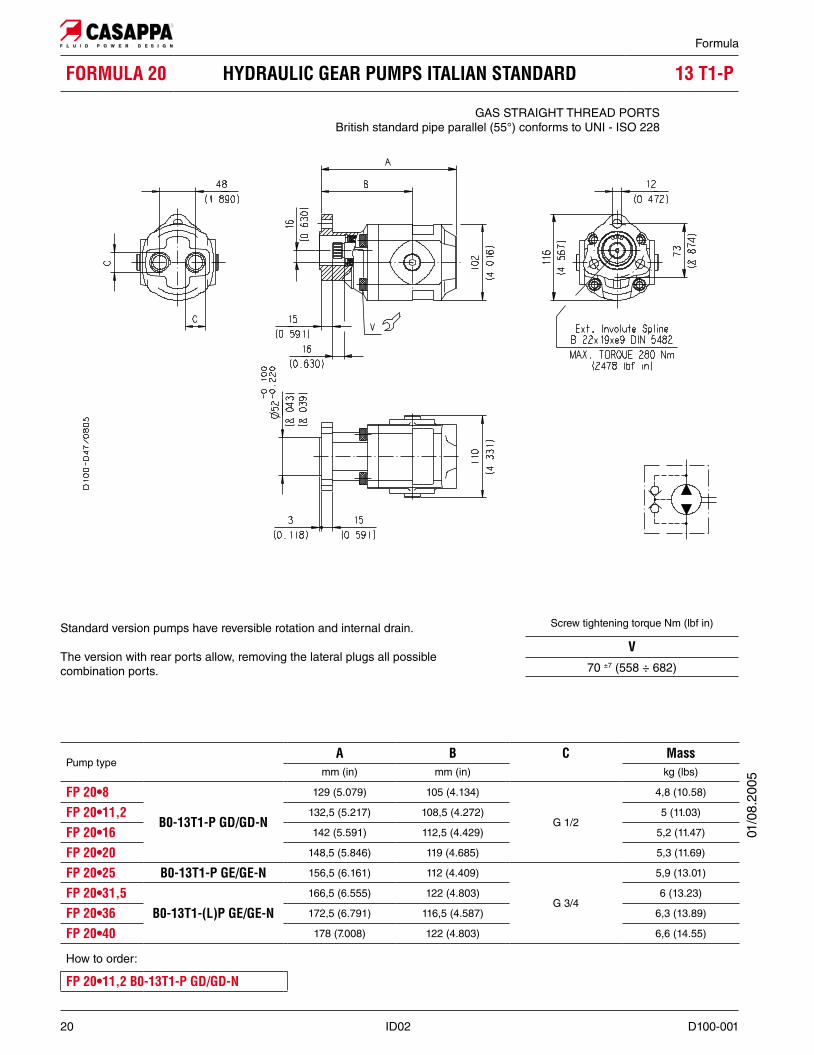
FORMULA 20 HYDRAULIC GEAR PUMPS ITALIAN STANDARD
GAS STRAIGHT THREAD PORTSBritish standard pipe parallel (55°) conforms to UNI - ISO 228
Pump typeA B C Mass
mm (in) mm (in) kg (lbs)
132,5 (5.217) 105 (4.134)
G 1/2
4,8 (10.58)
136 (5.354) 108,5 (4.272) 5 (11.03)
145,5 (5.728) 112,5 (4.429) 5,2 (11.47)
152 (5.984) 119 (4.685) 5,3 (11.69)
160 (6.299) 112 (4.409)
G 3/4
5,9 (13.01)
170 (6.693) 122 (4.803) 6 (13.23)
175,5 (6.909) 116,5 (4.587) 6,3 (13.89)
181 (7.126) 122 (4.803) 6,6 (14.55)
How to order:
Standard version pumps have reversible rotation and internal drain.
01/0
8.20
05
Screw tightening torque Nm (lbf in)
V70 ±7 (558 ÷ 682)
Formula
20 ID02 D100-001
FORMULA 20 HYDRAULIC GEAR PUMPS ITALIAN STANDARD
GAS STRAIGHT THREAD PORTSBritish standard pipe parallel (55°) conforms to UNI - ISO 228
Standard version pumps have reversible rotation and internal drain.
The version with rear ports allow, removing the lateral plugs all possiblecombination ports.
Pump typeA B C Mass
mm (in) mm (in) kg (lbs)
129 (5.079) 105 (4.134)
G 1/2
4,8 (10.58)
132,5 (5.217) 108,5 (4.272) 5 (11.03)
142 (5.591) 112,5 (4.429) 5,2 (11.47)
148,5 (5.846) 119 (4.685) 5,3 (11.69)
156,5 (6.161) 112 (4.409)
G 3/4
5,9 (13.01)
166,5 (6.555) 122 (4.803) 6 (13.23)
172,5 (6.791) 116,5 (4.587) 6,3 (13.89)
178 (7.008) 122 (4.803) 6,6 (14.55)
How to order:
Screw tightening torque Nm (lbf in)
V70 ±7 (558 ÷ 682)
01/0
8.20
05

Formula
D100-001 ID02 21
FORMULA 20 HYDRAULIC GEAR PUMPS ITALIAN STANDARD
Pump typeA B C Mass
mm (in) mm (in) kg (lbs)
145,5 (5.728) 112,5 (4.429)G 1/2
5,2 (11.47)
152 (5.984) 119 (4.685) 5,3 (11.69)
160 (6.299) 112 (4.409)
G 3/4
5,9 (13.01)
170 (6.693) 122 (4.803) 6 (13.23)
181 (7.126) 122 (4.803) 6,6 (14.55)
How to order:
Standard version pumps have reversible rotation and internal drain.
GAS STRAIGHT THREAD PORTSBritish standard pipe parallel (55°) conforms to UNI - ISO 228
01/0
8.20
05
Screw tightening torque Nm (lbf in)
V70 ±7 (558 ÷ 682)

Formula
22 ID02 D100-001
FORMULA 20 HYDRAULIC GEAR PUMPS ITALIAN STANDARD
Pump typeA B C Mass
mm (in) mm (in) kg (lbs)
142 (5.591) 112,5 (4.429)G 1/2
5,2 (11.47)
148,5 (5.846) 119 (4.685) 5,3 (11.69)
156,5 (6.161) 112 (4.409)
G 3/4
5,9 (13.01)
166,5 (6.555) 122 (4.803) 6 (13.23)
178 (7.008) 122 (4.803) 6,6 (14.55)
How to order
Standard version pumps have reversible rotation and internal drain.
The version with rear ports allow, removing the lateral plugs all possiblecombination ports.
GAS STRAIGHT THREAD PORTSBritish standard pipe parallel (55°) conforms to UNI - ISO 228
Screw tightening torque Nm (lbf in)
V70 ±7 (558 ÷ 682)
01/0
8.20
05

Formula
D100-001 ID02 23
HYDRAULIC GEAR PUMPS ISO STANDARD
Pump typeA B C D Mass
mm (in) mm (in) IN OUT kg (lbs)
S D R B
168,5 (6.634) 118,5 (4.665) G 1/2 G 1/2 10,65 (23.48)
174,5 (6.870) 124,5 (4.902)
G 3/4 G 3/4
11,10 (24.48)
179,5 (7.067) 124,5 (4.902) 11,56 (25.49)
182,5 (7.185) 127,5 (5.020) 12,10 (26.68)
185,5 (7.303) 130,5 (5.138) 12,30 (27.12)
190,5 (7.500) 128,5 (5.059)
G1G1
12,45 (27.45)
196,5 (7.736) 134,5 (5.295) 13,00 (28.67)
204,5 (8.051) 135,5 (5.335) 13,70 (30.21)
209,5 (8.248) 140,5 (5.531)
G 1 1/4
14,05 (30.98)
226,5 (8.917) 145,5 (5.728)G 1 1/4
15,55 (34.29)
242,5 (9.547) 161,5 (6.358) 17,05 (37.60)
Rotation: S=left - D=right - R=reversible - B=reversible internal drain How to order:
Multiple pumps available.For the applications without radial load is available the light weight version without outboard bearing.(For more information please consult our technical sales department).
Max. radial load 9000 N (2025 lbf)
24 mm (0.945 in) from mounting face (Fr)
GAS STRAIGHT THREAD PORTSBritish standard pipe parallel (55°) conforms to UNI - ISO 228
01/0
8.20
05
Screw tightening torque Nm (lbf in)
V70 ±7 (558 ÷ 682)

Formula
24 ID02 D100-001
HYDRAULIC GEAR PUMPS ITALIAN STANDARD
Pump typeA B C D Mass
mm (in) mm (in) IN OUT kg (lbs)
S D R B
T1
T2
150,5 (5.925) 100,5 (3.957) G 1/2 G 1/2 9 (19.85)
156,5 (6.161) 106,5 (4.193)
G 3/4 G 3/4
9,3 (20.51)
161,5 (6.358) 106,5 (4.193) 9,6 (21.17)
164,5 (6.476) 109,5 (4.311) 9,8 (21.61)
167,5 (6.594) 112,5 (4.429) 10 (22.05)
172,5 (6.791) 110,5 (4.350)
G1G1
10,3 (22.71)
178,5 (7.028) 116,5 (4.587) 10,7 (23.59)
186,5 (7.343) 117,5 (4.623) 10,9 (24.03)
191,5 (7.539) 122,5 (4.823)
G 1 1/4
11 (24.26)
217 (8.543) 136 (5.354)G 1 1/4
11,5 (25.36)
233 (9.173) 152 (5.984) 12,3 (27.12)
Rotation: S=left - D=right - R=reversible - B=reversible internal drain How to order:
z Only available in T1 version.
GAS STRAIGHT THREAD PORTSBritish standard pipe parallel (55°) conforms to UNI - ISO 228
Flange T1
Flange T2Only for rotation S-D
Screw tightening torque Nm (lbf in)
V70 ±7 (558 ÷ 682)
01/0
8.20
05

Formula
D100-001 ID02 25
HYDRAULIC GEAR PUMPS ITALIAN STANDARD
GAS STRAIGHT THREAD PORTSBritish standard pipe parallel (55°) conforms to UNI - ISO 228
Pump typeA B C D Mass
mm (in) mm (in) IN OUT kg (lbs)
S D R B
T1
T2
178,5 (7.028) 116,5 (4.587) G 1
G 1
10,7 (23.59)
191,5 (7.539) 122,5 (4.823) G 1 1/4 11 (24.26)
Rotation: S=left - D=right - R=reversible - B=reversible internal drain How to order:
Flange T1
Flange T2Only for rotation S-D
01/0
8.20
05
Screw tightening torque Nm (lbf in)
V70 ±7 (558 ÷ 682)

Formula
26 ID02 D100-001
HYDRAULIC GEAR PUMPS ITALIAN STANDARD
Pump typeA B C D Mass
mm (in) mm (in) IN OUT kg (lbs)
S D R B
178,5 (7.028) 116,5 (4.587) G 1
G 1
10,7 (23.59)
191,5 (7.539) 122,5 (4.823) G 1 1/4 11 (24.26)
Rotation: S=left - D=right - R=reversible - B=reversible internal drain How to order:
GAS STRAIGHT THREAD PORTSBritish standard pipe parallel (55°) conforms to UNI - ISO 228
Screw tightening torque Nm (lbf in)
V70 ±7 (558 ÷ 682)
01/0
8.20
05

Formula
D100-001 ID02 27
HYDRAULIC GEAR PUMPS SAE STANDARD SAE
Pump typeA B C D Ports code Mass
mm (in) mm (in) IN OUT IN OUT kg (lbs)
148 (5.827) 98 (3.858) 3/4-16 UNF-2B 3/4-16 UNF-2B OB OB 10,4 (22.93)
154 (6.063) 104 (4.094)
1-1/16-12 UN-2B ODOD
10,8 (23.81)
159 (6.260) 104 (4.094) 11,3 (24.92)
162 (6.378) 107 (4.213) 1-1/16-12 UN-2B 11,5 (25.36)
165 (6.496) 110 (4.331)
1-5/16-12 UN-2B OF11,8 (26.02)
170 (6.693) 108 (4.252)1-3/16-12 UN-2B OE
12 (26.46)
176 (6.929) 114 (4.488) 13 (28.67)
184 (7.244) 115 (4.528)1-5/8-12 UN-2B 1-5/16-12 UN-2B OG OF
13,4 (29.55)
189 (7.441) 120 (4.724) 13,9 (30.65)
z Only available in version 2.
SAE STRAIGHT THREAD PORTS J514American straight thread UNC-UNF 60° conforms to ANSI B 1.1.
Screw tightening torque Nm (lbf in)
V70 ±7 (558 ÷ 682)
01/0
8.20
05

28 ID02 D100-001
Formula
SAE
Version for applications without radial and axial load on the drive shaft.
Version for applications with low radial load and without axial load on the drive shaft.
Special version with independent shaft for applications with low ra-dial load and without axial load on the drive shaft.
SAE
SAE “B” SPLINE
�
SAE “B” STRAIGHT
�
SAE “BB” SPLINE
�
SAE “BB” STRAIGHT
�
��
210
01/0
8.20
05
Ext. Involute Spline SAE J498B with major diameter modified 13 teeth - 16/32 Pitch - 30 deg Flat Root - Side fit - Class 1
Ext. Involute Spline SAE J498B with major diameter modified 15 teeth - 16/32 Pitch - 30 deg Flat Root - Side fit - Class 1

Formula
D100-001 ID02 29
SAE01
/08.
2005
X= Distance of the radial load result from the mounting flange.
Fatigue life (hours) Lh= 1000 [h]
Each curve has been obtained at(1) 1000 min-1 (4) 2500 min-1
(2) 1500 min-1 (5) 3000 min-1
(3) 2000 min-1
VERSION
1- 2
30 ID02 D100-001
Formula
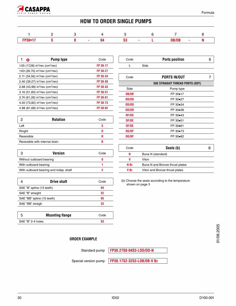
1 Code
1.05 (17,28) in3/rev (cm3/rev) ·
1.63 (26,70) in3/rev (cm3/rev) ·
2.11 (34,56) in3/rev (cm3/rev) ·
2.40 (39,27) in3/rev (cm3/rev) ·
2.68 (43,98) in3/rev (cm3/rev) ·
3.16 (51,83) in3/rev (cm3/rev) ·
3.74 (61,26) in3/rev (cm3/rev) ·
4.50 (73,82) in3/rev (cm3/rev) ·
4.98 (81,68) in3/rev (cm3/rev) ·
2 Rotation Code
Left S
Ringht D
Reversible R
Reversible with internal drain B
3 Version Code
Without outboard bearing 0
With outboard bearing 1
With outboard bearing and indep. shaft 2
4 Drive shaft Code
SAE “B” spline (13 teeth)
SAE “B” straight
SAE “BB” spline (15 teeth)
SAE “BB” straigh
5 Code
SAE “B” 2-4 holes
Code Ports position 6
L Side
Code 7
Side Pump type
FP 30z17
FP 30z27
FP 30z34
FP 30z38
FP 30z43
FP 30z51
FP 30z61
FP 30z73
FP 30z82
Code 8
N Buna N (standard)
V Viton
N Bz Buna N and Bronze thrust plates
V Bz Viton and Bronze thrust plates
(b) Choose the seals according to the temperature shown on page 3
HOW TO ORDER SINGLE PUMPS
1 2 3 4 5 6 7 8S 0 - - L - N
O
01/0
8.20
05
ORDER EXAMPLE
Standard pump
Special version pump

Formula
D100-001 ID02 31
HYDRAULIC GEAR PUMPS ISO STANDARD
Pump typeA B C D Mass
mm (in) mm (in) IN OUT kg (lbs)
S D R B
199 (7.835) 131 (5.157)G 1 G 3/4
18,65 (41.12)
203 (7.992) 135 (5.315) 19,30 (42.56)
208 (8.189) 140 (5.512)G 1 1/4
G1
19,75 (43.55)
216 (8.504) 141 (5.551) 21 (46.31)
225 (8.858) 150 (5.906)G 1 1/2
22,10 (48.73)
231 (9.094) 156 (6.142) 22,90 (50.49)
Rotation: S=left - D=right - R=reversible - B=reversible internal drain How to order:
GAS STRAIGHT THREAD PORTSBritish standard pipe parallel (55°) conforms to UNI - ISO 228
Max. radial load 9000 N (2025 lbf)24 mm (0.945 in) from mounting face (Fr)
01/0
8.20
05
Screw tightening torque Nm (lbf in)
V100 ±10 (797 ÷ 974)

Formula
32 ID02 D100-001
HYDRAULIC GEAR PUMPS ITALIAN STANDARD
Pump typeA B C D Mass
mm (in) mm (in) IN OUT kg (lbs)
S D R B
T1
T2
187,5 (7.382) 119,5 (4.705)G 1 G 3/4
16,1 (35.50)
191,5 (7.539) 123,5 (4.862) 16,5 (36.38)
196,5 (7.736) 128,5 (5.059)G 1 1/4
G 1
17 (37.49)
204,5 (8.051) 129,5 (5.098) 18 (39.69)
213,5 (8.406) 138,5 (5.453)G 1 1/2
19,5 (43.00)
219,5 (8.642) 144,5 (5.689) 20 (44.10)
Rotation: S=left - D=right - R=reversible - B=reversible internal drain How to order:
GAS STRAIGHT THREAD PORTSBritish standard pipe parallel (55°) conforms to UNI - ISO 228
Flange T1
Flange T2Only for rotation S-D
Screw tightening torque Nm (lbf in)
V100 ±10 (797 ÷ 974)
01/0
8.20
05

Formula
D100-001 ID02 33
HYDRAULIC GEAR PUMPS SAE STANDARD SAE
Pump typeA B C D Ports code Mass
mm (in) mm (in) IN OUT IN OUT kg (lbs)
188,5 (7.421) 120,5 (4.744)1-5/16-12 UN-2B 1-1/16-12 UN-2B OF OD
19,5 (43.00)
192,5 (7.579) 124,5 (4.902) 20 (44.10)
197,5 (7.776) 129,5 (5.098)1-5/8-12 UN-2B
1-5/16-12 UN-2B
OGOF
20,5 (45.20)
205,5 (8.091) 130,5 (5.138) 21 (46.31)
214,5 (8.445) 139,5 (5.492)1-7/8-12 UN-2B OH
23 (50.72)
220,5 (8.681) 145,5 (5.728) 25 (55.13)
SAE STRAIGHT THREAD PORTS J514American straight thread UNC-UNF 60° conforms to ANSI B 1.1.
01/0
8.20
05
Screw tightening torque Nm (lbf in)
V100 ±10 (797 ÷ 974)

34 ID02 D100-001
Formula
SAE
Version for applications without radial and axial load on the drive shaft.
Version for applications with low radial load and without axial load on the drive shaft.
Special version with independent shaft for applications with low ra-dial load and without axial load on the drive shaft.
SAE
SAE “C” SPLINE
�
SAE “C” STRAIGHT
�
�
PUMP - VERSION - SHAFT AVAILABILITY TABLE SAE
Pump typeVERSION
0 1 206 06 06 - 34
SHAF
T
06 - 34 06 - 34 06 - 34
06 - 34 06 - 34 06 - 34
06 06 06 - 34
06 - 34 06 - 34 06 - 34
06 - 34 06 - 34 06 - 34
210
Ext. Involute Spline SAE J498B with major diameter modified 14 teeth - 12/24 Pitch - 30 deg Flat Root - Side fit - Class 1
01/0
8.20
05

Formula
D100-001 ID02 35
SAE
VERSION
1- 2
01/0
8.20
05
X= Distance of the radial load result from the mounting flange.
Fatigue life (hours) Lh= 1000 [h]
Each curve has been obtained at(1) 1000 min-1 (4) 2500 min-1
(2) 1500 min-1 (5) 3000 min-1
(3) 2000 min-1

36 ID02 D100-001
Formula
HOW TO ORDER SINGLE PUMPS
1 2 3 4 5 6 7 8S 0 - - L - N
1 Code
3.75 (61,43) in3/rev (cm3/rev) ·
4.43 (72,60) in3/rev (cm3/rev) ·
5.28 (86,56) in3/rev (cm3/rev) ·
6.64 (108,90) in3/rev (cm3/rev) ·
8.18 (134,03) in3/rev (cm3/rev) ·
9.20 (150,79) in3/rev (cm3/rev) ·1
2 Rotation Code
Left S
Ringht D
Reversible R
Reversible with internal drain B
3 Version Code
Without outboard bearing 0
With outboard bearing 1
With outboard bearing and indep. shaft 2
4 Drive shaft Code
SAE “C” spline (14 teeth)
SAE “C” straight
5 Code
SAE “C” 2-4 holes
Code Ports position 6
L Side
Code 7
Side Pump type
FP 40z63
FP 40z73
FP 40z87
FP 40z109
FP 40z133
FP 40z151
Code 8
N Buna N (standard)
V Viton
N Bz Buna N and Bronze thrust plates
V Bz Viton and Bronze thrust plates
(a) Choose the seals according to the temperature shown on page 3
ORDER EXAMPLE
Standard pump
Special version pump
01/0
8.20
05

Formula
D100-001 ID02 37
MULTIPLE PUMPS
FORMULA series pumps can be coupled together in combination. Where imput power requirement of each ele-ment varies, that with the greater requirement must be at the drive shaft end, and progressively smaller to the rear.
Features and performances are the same as the corresponding single pumps, but pressures must be limited by the transmissible torque of the drive and connecting shafts. To have appropriate data, use the formula below.
The maximum rotational speed is that of the lowest rated speed of the single units incorporated.
M lbf in [Nm] Torque
V in3/rev [cm3/rev] Displacement
"p psi [bar] Pressure
Șhm= Șm (V, ∆p, n) (≈ 0,90) Hydro-mechanical efficiency
M =Mtheor.
[Nm]Șhm
Mtheor.=3/rev)
62,83
DRIVE SHAFT SELECTIONThe torque absorbed from the shaft of the first pump results from the sum of the torques due to all single stages. The achieved value must not exceed the maximum torque limit given for the shaft of the first pump. Diagrams providing approximate selection data will be found on page 38.
-sure of 2900 psi (200 bar) and the second pump at a pressure of 2175 psi (150 bar), the grafh 1 shows that the torque
(160 Nm) [acceptable value because it don’t exceed the maximum drive shaft torque that is 2478 lbf in (280 Nm), see page 42]. The torque to be transmitted by the first drive shaft will thus be 1974+1416=3390 lbf in (223+160= 383 Nm), this value must not exceed the shaft’s maximum rated value.
O
Rep
lace
s: 0
1/08
.200
5O
03/
05.2
013

Formula
38 ID02 D100-001
ABSORBED TORQUE
FP 20 KP 20-PLP 20
01/0
8.20
05

D100-001 ID02 39
Formula
ITALIAN STANDARD
Front Rear
FORMULA 20 MULTIPLE PUMPS COMBINATION01
/08.
2005
FORMULA 20 + FORMULA 20 STANDARD VERSION
FORMULA 20 END DRIVE SHAFT

Formula
40 ID02 D100-001
Front RearIntermediate
Front Rear
Front Rear
MULTIPLE PUMPS COMBINATION
01/0
8.20
05
STANDARD VERSION
STANDARD VERSION
STANDARD VERSION

D100-001 ID02 41
Formula
Special front section arranged to fit single pumps.To order please consult our technical sales department.
ITALIAN STANDARD ISO STANDARD
01/0
8.20
05MULTIPLE PUMPS SPECIAL COMBINATION
Front
KAPPA 20 - 12 E2
POLARIS 20 - 12 E2
KIT
KIT

Formula
42 ID02 D100-001
Front Rear
Front Rear
Front Rear
Intermediate
MULTIPLE PUMPS COMBINATION
01/0
8.20
05
STANDARD VERSION
STANDARD VERSION
STANDARD VERSION

D100-001 ID02 43
Formula
Front Rear
Front Rear
ITALIAN STANDARD ISO STANDARD
SPLINE SAE STANDARD STRAIGHT SAE STANDARD
MULTIPLE PUMPS COMBINATION
STANDARD VERSION
STANDARD VERSION
01/0
8.20
05

Formula
44 ID02 D100-001
FORMULA 20 HYDRAULIC GEAR PUMPS ITALIAN STANDARD
GAS STRAIGHT THREAD PORTSBritish standard pipe parallel (55°) conforms to UNI - ISO 228
Screw tightening torque Nm (lbf in)
V70 ±7 (558 ÷ 682)
01/0
8.20
05

Formula
D100-001 ID02 45
FORMULA 20 HYDRAULIC GEAR PUMPS ITALIAN STANDARD
Pump typeA B C D
Emm (in) mm (in) mm (in) mm (in)
105 (4.272) 37,5 (1.476) 29 (1.142) 27,5 (1.083)
G 1/2108,5 (4.272) 38,5 (1.516) 32,5 (1.280) 27,5 (1.083)
112,5 (4.429) 43 (1.693) 36,5 (1.437) 32,5 (1.280)
119 (4.685) 43 (1.693) 43 (1.693) 33 (1.299)
112 (4.409) 58 (2.283) 36 (1.417) 48 (1.890)G 3/4
122 (4.803) 58 (2.283) 46 (1.811) 48 (1.890)
The lenght of a triple pump is obtained with the sum of the following dimensions: A+B+C+B+C+D.
01/0
8.20
05
(for double pump omit the intermediate pump)
Front pump / Intermediate
pump / Rear pump
Rotation -
Seals
S -
(1) S= Left - D= Right (2) See page 3 (for Buna N seals no code)

Formula
46 ID02 D100-001
HYDRAULIC GEAR PUMPS ITALIAN STANDARD
GAS STRAIGHT THREAD PORTSBritish standard pipe parallel (55°) conforms to UNI - ISO 228�
Flange T1
Flange T2
Screw tightening torque Nm (lbf in)
V70 ±7 (558 ÷ 682)
01/0
8.20
05

Formula
D100-001 ID02 47
HYDRAULIC GEAR PUMPS ITALIAN STANDARD
Pump type
A (19 T) B C D E F G Ports code
mm (in) mm (in) mm (in) mm (in) IN OUT mm (in) IN OUT
111,5 (4.390) 63 (2.480) 29 (1.142) 49 (1.929)
G 3/4 G 3/4130 (5.118)
GE GE117,5 (4.626) 63 (2.480) 35 (1.378) 49 (1.929)
122,5 (4.823) 63(2.480) 40 (1.575) 49 (1.929)
125,5 (4.941) 63(2.480) 43 (1.693) 49 (1.929)
128,5 (5.059) 63 (2.480) 46 (1.811) 49 (1.929)
125,5 (4.941) 71 (2.795) 43 (1.693) 57 (2.244)
G 1G 1
GFGF
132,5 (5.217) 70 (2.756) 50 (1.969) 56 (2.205)
135 (5.315)140,5 (5.531) 70 (2.756) 58 (2.283) 56 (2.205)
z 145,5 (5.728) 70 (2.756) --- --- G 1 1/4 GG
(z) Available only for front and intermediate section.
The lenght of a triple pump is obtained with the sum of the following dimensions: A+B+C+B+C+D.
(�) Dimension “A”.ISO and SAE version
mm (in)
A (19 T) + 18 (0.709)
A (19 T) - 2,5 (0.098)
(for double pump omit the intermediate pump)
Front pump / Intermediate
pump / Rear pump
Rotation -
Seals
S -
(1) S= Left - D= Right (2) See page 3 (for Buna N seals no code)
01/0
8.20
05
Formula
48 ID02 D100-001
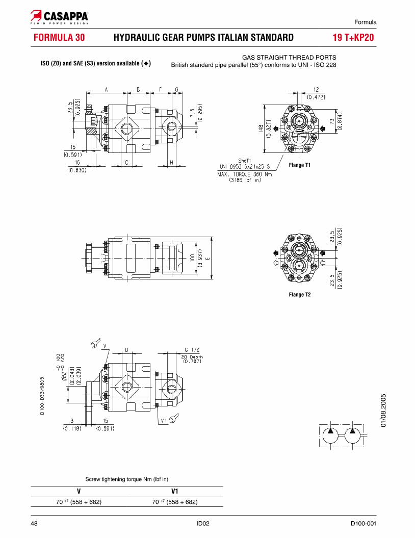
HYDRAULIC GEAR PUMPS ITALIAN STANDARD
Flange T1
Flange T2
�GAS STRAIGHT THREAD PORTS
British standard pipe parallel (55°) conforms to UNI - ISO 228
Screw tightening torque Nm (lbf in)
V V170 ±7 (558 ÷ 682) 70 ±7 (558 ÷ 682)
01/0
8.20
05
Formula
D100-001 ID02 49
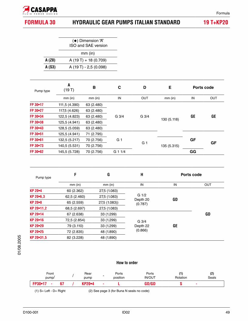
HYDRAULIC GEAR PUMPS ITALIAN STANDARD
(�) Dimension “A” ISO and SAE version
mm (in)
A (19 T) + 18 (0.709)
A (19 T) - 2,5 (0.098)
Pump type
A (19 T) B C D E Ports code
mm (in) mm (in) IN OUT mm (in) IN OUT
111,5 (4.390) 63 (2.480)
G 3/4 G 3/4130 (5.118)
GE GE117,5 (4.626) 63 (2.480)
122,5 (4.823) 63 (2.480)
125,5 (4.941) 63 (2.480)
128,5 (5.059) 63 (2.480)
125,5 (4.941) 71 (2.795)
G 1G 1
GFGF
132,5 (5.217) 70 (2.756)
135 (5.315)140,5 (5.531) 70 (2.756)
145,5 (5.728) 70 (2.756) G 1 1/4 GG
Pump typeF G H Ports code
mm (in) mm (in) IN IN OUT
60 (2.362) 27,5 (1.083)G 1/2
Depth 20(0.787)
GD
GD
62,5 (2.460) 27,5 (1.083)
65 (2.559) 27,5 (1.083))
68,5 (2.697) 27,5 (1.083)
67 (2.638) 33 (1.299)
G 3/4Depth 22(0.866)
GE72,5 (2.854) 33 (1.299)
79 (3.110) 33 (1.299)
72 (2.835) 48 (1.890)
82 (3.228) 48 (1.890)
How to order
Front pump/ / Rear
pump - Ports position
Ports IN/OUT
Rotation
Seals
- - L S -
(1) S= Left - D= Right (2) See page 3 (for Buna N seals no code)
01/0
8.20
05

Formula
50 ID02 D100-001
HYDRAULIC GEAR PUMPS ITALIAN STANDARD
Flange T1
Flange T2
�GAS STRAIGHT THREAD PORTS
British standard pipe parallel (55°) conforms to UNI - ISO 228
Screw tightening torque Nm (lbf in)
V z V270 ±7 (558 ÷ 682) 70 ±7 (558 ÷ 682) 70 ±7 (558 ÷ 682)
(z) With cast iron front cover
01/0
8.20
05

Formula
D100-001 ID02 51
HYDRAULIC GEAR PUMPS ITALIAN STANDARD
(�) Dimension “A”ISO and SAE version
mm (in)
A (19 T) + 18 (0.709)
A (19 T) - 2,5 (0.098)
Pump type
A (19 T) B C D E Ports code
mm (in) mm (in) IN OUT mm (in) IN OUT
111,5 (4.390) 63 (2.480)
G 3/4 G 3/4130 (5.118)
GE GE117,5 (4.626) 63 (2.480)
122,5 (4.823) 63 (2.480)
125,5 (4.941) 63 (2.480)
128,5 (5.059) 63 (2.480)
125,5 (4.941) 71 (2.795)
G 1G 1
GFGF
132,5 (5.217) 70 (2.756)
135 (5.315)140,5 (5.531) 70 (2.756)
145,5 (5.728) 70 (2.756) G 1 1/4 GG
Pump typeF G H Ports code
mm (in) mm (in) IN IN OUT
43,8 (1.722) 49,3 (1.941)
G 1/2Depth 17(0.669)
GD
GD
45 (1.772) 50,5 (1.988)
45,5 (1.791) 51 (2.008)
46,3 (1.821) 51,8 (2.039)
46,9 (1.846) 52,4 (2.063)
48,3 (1.900) 53,8 (2.118)
48,5 (1.909) 54 (2.126)
51 (2.008) 56,5 (2.224)
G 3/4Depth 18(0.709)
GE
52,8 (2.077) 58,3 (2.295)
54,5 (2.146) 60 (2.553)
56 (2.205) 61,5 (2.421)
58,8 (2.315) 64,3 (2.531)
60 (2.362) 65,5 (2.579)
61,4 (2.417) 66,9 (2.634)
65 (2.559) 70,5 (2.776)
How to order
Front pump/ / Rear
pump - Ports position
Ports IN/OUT
Rotation -
Seals
- - L S -
(1) S= Left - D= Right (2) See page 3 (for Buna N seals no code)
01/0
8.20
05

Formula
52 ID02 D100-001
HYDRAULIC GEAR PUMPS ITALIAN STANDARD
GAS STRAIGHT THREAD PORTSBritish standard pipe parallel (55°) conforms to UNI - ISO 228
�
Flange T1
Flange T2
Screw tightening torque Nm (lbf in)
V V1100 ±10 (797 ÷ 974) 100 ±10 (797 ÷ 974)
01/0
8.20
05

Formula
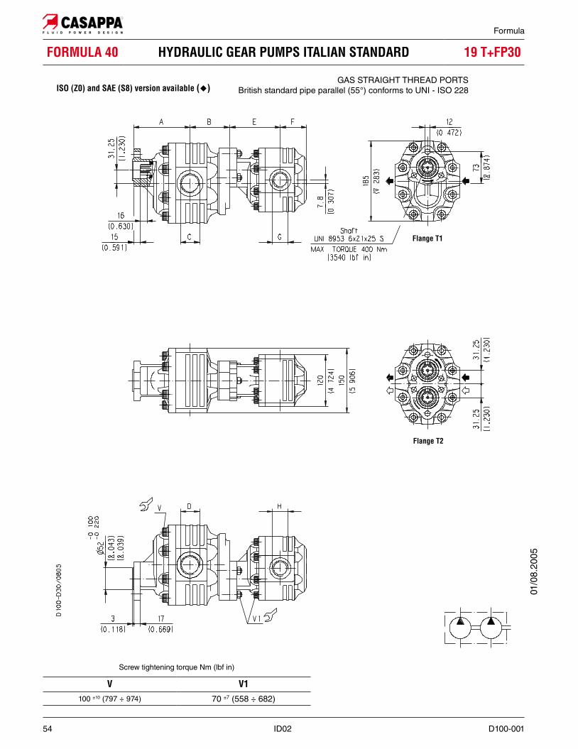
D100-001 ID02 53
HYDRAULIC GEAR PUMPS ITALIAN STANDARD
Pump type
A (19 T) B C D E F Ports code
mm (in) mm (in) mm (in) mm (in) IN OUT IN OUT
119,5 (4.705) 57,5 (2.264) 65,5 (2.579) 68 (2.677)G 1 G 3/4 GF GE
123,5 (4.862) 57,5 (2.264) 69,5 (2.736) 68 (2.677)
128,5 (5.059) 57,5 (2.264) 74,5 (2.933) 68 (2.677)G 1 1/4
G 1
GGGF
129,5 (5.098) 64,5 (2.539) 75,5 (2.972) 75 (2.953)
138,5 (5.453) 64,5 (2.539) 84,5 (3.327) 75 (2.953)G 1 1/2 GH
144,5 (5.689) 64,5 (2.539) 90,5 (3.563) 75 (2.953)
The lenght of a triple pump is obtained with the sum of the following dimensions: A+B+C+B+C+D.
(�) Dimension “A” ISO version
mm (in)
A (19 T) + 11,5 (0.453)
(for double pump omit the intermediate pump)
Front pump / Intermediate
pump / Rear pump
Rotation -
Seals
S -
(1) S= Left - D= Right (2) See page 3 (for Buna N seals no code)
01/0
8.20
05
Formula
54 ID02 D100-001
HYDRAULIC GEAR PUMPS ITALIAN STANDARD
Flange T1
Flange T2
�GAS STRAIGHT THREAD PORTS
British standard pipe parallel (55°) conforms to UNI - ISO 228
Screw tightening torque Nm (lbf in)
V V1100 ±10 (797 ÷ 974) 70 ±7 (558 ÷ 682)
01/0
8.20
05

Formula
D100-001 ID02 55
HYDRAULIC GEAR PUMPS ITALIAN STANDARD
Pump type
A (19 T) B C D Ports code
mm (in) mm (in) IN OUT IN OUT
119,5 (4.705) 84,5 (3.327)G 1 G 3/4 GF GE
123,5 (4.862) 84,5 (3.327)
128,5 (5.059) 84,5 (3.327)G 1 1/4
G 1
GGGF
129,5 (5.098) 91,5 (3.602)
138,5 (5.453) 91,5 (3.602)G 1 1/2 GH
144,5 (5.689) 91,5 (3.602)
Pump typeE F G H
mm (in) mm (in) IN IN
100,5 (5.925) 50 (1.969) G 1/2 G 1/2
106,5 (4.193) 50 (1.969)
G 3/4 G 3/4106,5 (4.193) 55 (2.165)
109,5 (4.311) 55 (2.165)
112,5 (4.429) 55 (2.165)
110,5 (4.350) 62 (2.441)
G 1G 1
116,5 (4.587) 62 (2.441)
117,5 (4.623) 69 (2.717)
122,5 (4.823) 69 (2.717) G 1 1/4
(�) Dimension “A” ISO and SAE version
mm (in)
A (19 T) + 11,5 (0.453)
A (19 T) + 1 (0.039)
How to order
Front pump / Rear
pump
Rotation - Seals
- S -
(1) S= Left - D= Right (2) See page 3 (for Buna N seals no code)
01/0
8.20
05

Formula
56 ID02 D100-001
HYDRAULIC GEAR PUMPS ITALIAN STANDARD
Flange T1
Flange T2
�GAS STRAIGHT THREAD PORTS
British standard pipe parallel (55°) conforms to UNI - ISO 228
Screw tightening torque Nm (lbf in)
V V1100 ±10 (797 ÷ 974) 70 ±7 (558 ÷ 682)
01/0
8.20
05

Formula
D100-001 ID02 57
HYDRAULIC GEAR PUMPS ITALIAN STANDARD
Pump type
A (19 T) B C D Ports code
mm (in) mm (in) IN OUT IN OUT
119,5 (4.705) 84,5 (3.327)G 1 G 3/4 GF GE
123,5 (4.862) 84,5 (3.327)
128,5 (5.059) 84,5 (3.327)G 1 1/4
G 1
GGGF
129,5 (5.098) 91,5 (3.602)
138,5 (5.453) 91,5 (3.602)G 1 1/2 GH
144,5 (5.689) 91,5 (3.602)
Pump typeE F G H
mm (in) mm (in) IN IN
105 (4.134) 27,5 (1.083)
G 1/2 G 1/2108,5 (4.272) 27,5 (1.083)
112,5 (4.429) 33 (1.299)
119 (4.685) 33 (1.299)
112 (4.409) 48 (1.890)
G 3/4 G 3/4122 (4.803) 48 (1.890)
116,5 (4.587) 59 (2.323)
122 (4.803) 59 (2.323)
(�) Dimension “A” ISO and SAE version
mm (in)
A (19 T) + 11,5 (0.453)
A (19 T) + 1 (0.039)
How to order
Front pump / Rear
pump
Rotation - Seals
- S -
(1) S= Left - D= Right (2) See page 3 (for Buna N seals no code)
01/0
8.20
05

Formula
58 ID02 D100-001
HYDRAULIC GEAR PUMPS ITALIAN STANDARD
Flange T1
Flange T2
�GAS STRAIGHT THREAD PORTS
British standard pipe parallel (55°) conforms to UNI - ISO 228
Screw tightening torque Nm (lbf in)
V V1100 ±10 (797 ÷ 974) 70 ±7 (558 ÷ 682)
01/0
8.20
05

Formula
D100-001 ID02 59
HYDRAULIC GEAR PUMPS ITALIAN STANDARD
Pump type
A (19 T) B C D Ports code
mm (in) mm (in) IN OUT IN OUT
119,5 (4.705) 84,5 (3.327)G 1 G 3/4 GF GE
123,5 (4.862) 84,5 (3.327)
128,5 (5.059) 84,5 (3.327)G 1 1/4
G 1
GGGF
129,5 (5.098) 91,5 (3.602)
138,5 (5.453) 91,5 (3.602)G 1 1/2 GH
144,5 (5.689) 91,5 (3.602)
Pump typeF G H Ports code
mm (in) mm (in) IN IN OUT
60 (2.362) 27,5 (1.083)G 1/2
Depth 20(0.787)
GD
GD
62,5 (2.460) 27,5 (1.083)
65 (2.559) 27,5 (1.083)
68,5 (2.697) 27,5 (1.083)
67 (2.638) 33 (1.299)
G 3/4Depth 22(0.866)
GE72,5 (2.854) 33 (1.299)
79 (3.110) 33 (1.299)
72 (2.835) 48 (1.890)
82 (3.228) 48 (1.890)
(�) Dimension “A” ISO and SAE version
mm (in)
A (19 T) + 11,5 (0.453)
A (19 T) + 1 (0.039)
How to order
Front pump / Rear
pump - Ports position
Ports IN/OUT
Rotation -
Seals
- - L S -
(1) S= Left - D= Right (2) See page 3 (for Buna N seals no code)
01/0
8.20
05

Formula
60 ID02 D100-001
HYDRAULIC GEAR PUMPS ITALIAN STANDARD
Flange T1
Flange T2
�GAS STRAIGHT THREAD PORTS
British standard pipe parallel (55°) conforms to UNI - ISO 228
Screw tightening torque Nm (lbf in)
V z V2100 ±10 (797 ÷ 974) 70 ±7 (558 ÷ 682) 70 ±7 (558 ÷ 682)
(z) With cast iron front cover.
01/0
8.20
05

Formula
D100-001 ID02 61
Pump type
A (19 T) B C D Ports code
mm (in) mm (in) IN OUT IN OUT
119,5 (4.705) 84,5 (3.327)G 1 G 3/4 GF GE
123,5 (4.862) 84,5 (3.327)
128,5 (5.059) 84,5 (3.327)G 1 1/4
G 1
GGGF
129,5 (5.098) 91,5 (3.602)
138,5 (5.453) 91,5 (3.602)G 1 1/2 GH
144,5 (5.689) 91,5 (3.602)
Pump typeE F G Ports code
mm (in) mm (in) mm (in) IN OUT
43,8 (1.722) 49,3 (1.941)
G 1/2Depth 17(0.669)
GD
GD
45 (1.772) 50,5 (1.988)
45,5 (1.791) 51 (2.008)
46,3 (1.821) 51,8 (2.039)
46,9 (1.846) 52,4 (2.063)
48,3 (1.900) 53,8 (2.118)
48,5 (1.909) 54 (2.126)
51 (2.008) 56,5 (2.224)
G 3/4Depth 18(0.709)
GE
52,8 (2.077) 58,3 (2.295)
54,5 (2.146) 60 (2.553)
56 (2.205) 61,5 (2.421)
58,8 (2.315) 64,3 (2.531)
60 (2.362) 65,5 (2.579)
61,4 (2.417) 66,9 (2.634)
65 (2.559) 70,5 (2.776)
(�) Dimension “A” ISO and SAE version
mm (in)
A (19 T) + 11,5 (0.453)
A (19 T) + 1 (0.039)
How to order
Front pump/ / Rear
pump - Ports position
Ports IN/OUT
Rotation -
Seals
- - L S -
(1) S= Left - D= Right (2) See page 3 (for Buna N seals no code)
01/0
8.20
05

Formula
62 ID02 D100-001
HYDRAULIC GEAR PUMPS SAE STANDARD SAE
SAE STRAIGHT THREAD PORTS J514American straight thread UNC-UNF 60° conforms to ANSI B 1.1
Screw tightening torque Nm (lbf in)
V V1100 ±10 (797 ÷ 974) 100 ±10 (797 ÷ 974)
Pump typeA B C D E F Ports
code
mm (in) mm (in) mm (in) mm (in) IN OUT IN OUT
120,5 (4.744) 57,5 (2.264) 65,5 (2.579) 68 (2.677)1-5/16-12 UN-2B 1-1/16-12 UN-2B OF OD
124,5 (4.902) 57,5 (2.264) 69,5 (2.736) 68 (2.677)
129,5 (5.098) 57,5 (2.264) 74,5 (2.933) 68 (2.677)1-5/8-12 UN-2B
1-5/16-12 UN-2B
OGOF
130,5 (5.138) 64,5 (2.539) 75,5 (2.972) 75 (2.953)
139,5 (5.492) 64,5 (2.539) 84,5 (3.327) 75 (2.953)1-7/8-12 UN-2B OH
145,5 (5.728) 64,5 (2.539) 90,5 (3.563) 75 (2.953)
The lenght of a triple pump is obtained with the sum of the following dimensions: A+B+C+B+C+D.
01/0
8.20
05

D100-001 ID02 63
Formula
SAE
Version for applications without radial and axial load on the drive shaft.
Version for applications with low radial load and without axial load on the drive shaft
Special version with independent shaft for applications with low ra-dial load and without axial load on the drive shaft.
SAE “C” SPLINE SAE “C” STRAIGHT
PUMP - VERSION - SHAFT AVAILABILITY TABLE SAE
� �
�
Pump typeVERSION
0 1 206 06 06 - 34
SHAF
T
06 - 34 06 - 34 06 - 34
06 - 34 06 - 34 06 - 34
06 06 06 - 34
06 - 34 06 - 34 06 - 34
06 - 34 06 - 34 06 - 34
210
Ext. Involute Spline SAE J498B with major diameter modified 14 teeth - 12/24 Pitch - 30 deg Flat Root - Side fit - Class 1
01/0
8.20
05
SAE

64 ID02 D100-001
Formula
HOW TO ORDER MULTIPLE PUMPS
1 2 3 4 5 6 7 8- - L
- L
- L - S - 0 N
1 Code
3.75 (61,43) in3/rev (cm3/rev)
4.43 (72,60) in3/rev (cm3/rev)
5.28 (86,56) in3/rev (cm3/rev)
6.64 (108,90) in3/rev (cm3/rev)
8.18 (134,03) in3/rev (cm3/rev)
9.20 (150,79) in3/rev (cm3/rev)
2 Drive shaft Code
SAE “C” spline (14 teeth)
SAE “C” straigh
3 Code
SAE “C” 2-4 holes
4 Ports position Code
Side L
Code 5
Side Pump type
FP 40z63
FP 40z73
FP 40z87
FP 40z109
FP 40z133
FP 40z151
Code Rotation 6
S Left
D Right
Code Version 7
0 Without outboard bearing
1 With outboard bearing
2 With outboard bearing and indep. shaft
Code 8
N Buna N (standard)
V Viton
N Bz Buna N and Bronze thrust plates
V Bz Viton and Bronze thrust plates
a) Choose the seals according to the temperature shown on page 3
ORDER EXAMPLE
Triple pump
01/0
8.20
05

Formula
D100-001 ID02 65
PORTS CONNECTORS TIGHTENING TORQUE
GAS STRAIGHT THREAD PORTS BSPP
CODE
Nm (lbf in) Nm (lbf in)
� 15 +1 133 ÷ 142 _ _
GD 20 +1 177 ÷ 186 50 +2,5 443 ÷ 465
GE 30 +2,5 266 ÷ 288 90 +5 797 ÷ 841
GF 50 +2,5 443 ÷ 465 130 +10 1151 ÷ 1239
GG 70 +5 620 ÷ 664 170 +15 1505 ÷ 1637
GH 70 +5 620 ÷ 664 _ _
ODT
CODICE
Nm (lbf in) Nm (lbf in)
� 15 +1 133 ÷ 142 _
OB 20 +1 177 ÷ 186 45 +2,5 398 ÷ 420
OD 40 +2,5 354 ÷ 376 120 +10 1062 ÷ 1151
OE 50 +2,5 443 ÷ 465 145 +10 1283 ÷ 1372
OF 60 +5 531 ÷ 575 170 +10 1505 ÷ 1593
OG 70 +5 620 ÷ 664 _ _
OH 100 +5 885 ÷ 929 _ _
(�) Drain port: FORMULA 30 and FORMULA 40 rear drain (R).
Tightening torque for low pressure side port.
Tightening torque for high pressure side port [values obtained at 350 bar (5075 psi)]
For reversible rotation, please consult only the tightening torque for high pressure side port.
O
Rep
lace
s: 0
1/08
.200
5O
03/
05.2
013

66 ID02 D100-001
Formula
Ordering code
Mass
N kg (lbs)
_2,7 (5.95)
Low load
The bearing support allows FORMULA Italian standard pumps to be cou-pled to P.T.O. of commercial vehicles.
Shaft UNI 8953 6x21x21 S
External SplineW 8x32x36 DIN-ISO 14
01/0
8.20
05

D100-001 ID02 67
Formula
Part Q.ty DescriptionOrdering
code
3Stud M 10x30 UNI 5911
Nut M 10Washer 10 DIN 7980
KIT 10 - A1 Gasket
1Splined coupling
MA 6x21x25 UNI 8953 - A 22x19 DIN 5482L= 31
Part Q.ty DescriptionOrdering
code
3 Stud M 10x30 UNI 5911Nut M 10 UNI 7473
1 Gasket
1 Splined couplingMA 6x21x25 UNI 8953 L= 31
01/0
8.20
05

68 ID02 D100-001
Formula
The FORMULA pumps in the application with radial load can be directly connected to the “ZF” P.T.O.
The FORMULA pumps in the application with radial load can be directly connected to the“ZF” P.T.O. with straight teeth gear using the SR9 support.
GasketGearPTO
Gasket
Splinedcoupling
PTO
01/0
8.20
05
D100-001 ID02 69
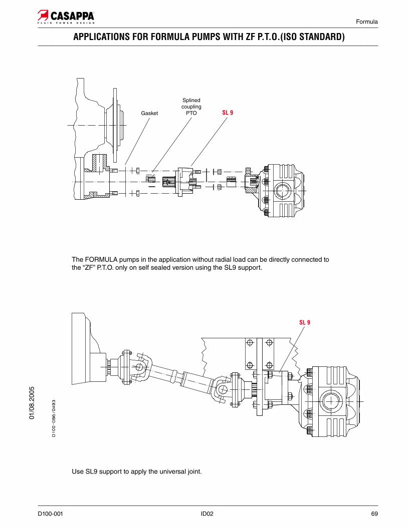
Formula
The FORMULA pumps in the application without radial load can be directly connected to the “ZF” P.T.O. only on self sealed version using the SL9 support.
Use SL9 support to apply the universal joint.
Gasket
Splinedcoupling
PTO
01/0
8.20
05

70 ID02 D100-001
Formula
CHANGING ROTATION
To change rotation of unidirectional pumps is necessary to operate in the following way:
1. Clean the pump externally with care.
2. Loosen, and remove, the clamp bolts (1)
3. Coat the sharp edges of the drive shaft (4) with adhesive tape and smear a layer of clean gre-ase on the shaft end extension to avoid dama-ging the lip of the shaft seal when removing the mounting flange.
4. Remove the mounting flange (2), taking care to keep the flange as straight as possible during removal. If the flange is stuck, tap around the edge with a fibre or rubber mallet in order to break away from the body. Ensure that while removing the front mounting flange, the drive shaft and other components remain position.
5. Ease the drive gear (4) up to facilitate removal the front plate (3), taking care that the precision ground surfaces do not become damaged, and remove the drive gear.
6. Remove the driven gear (5) without overturning. The rear plate has not to be removed.
7. Re-locate the driven gear (5) in the position previously occupied by the drive gear (4)
8. Re-locate the drive gear (4) in the position previously occupied by the driven gear (5)
9. Replace the front plate (3) in its original position.
10. Remove the grub screw (6) from the mounting flange (2) and re-locate it in the other threaded hole in the same flange.
11. Gently wipe the machined surface of the mounting flange (2) and the body with a flat hand stone.
12. Refit the front mounting flange (2) turned 180° from its original position.
13. Refit the clamp bolts (1) with the washers and tighten in a crisscross pattern to a torque value of 70 ±7 Nm (558 ÷ 682 lbf in).
14. Check that the pump rotates freely when the drive shaft (4) is turned by hand. If not a pressure plate seal may be pinched.
15. The pump is ready for installation with the original ro-tation reversed.
01/0
8.20
05
D100-001 ID02 71
Formula
INSTRUCTIONS
INSTALLATIONThe direction of rotation of single-rotation pumps must be the same as that of the drive shaft. Check that the coupling flange correctly aligns the transmission shaft and the pump shaft, the connection do not generate an axial or radial load on the pump shaft
TANKTank capacity must be sufficient for the system’s operating conditions ( ~ 3 times the amount of oil in circulation) to avoid overheating of the fluid. A heat exchanger should be installed if necessary. The intake and return lines in the tank must be spa-ced apart (by inserting a vertical divider) to prevent the return-line oil from being taken up again immediately.
LINESThe lines must have a major diameter which is at least as large as the diameter of pump ports, and must be perfectly sealed. To reduce loss of power, the lines should be as short as possible, reducing the sources of hydraulic resistance (elbow, throttling, gate valves, etc.) to a minimum. A length of flexible tubing is re-commended to reduce the transmission of vibrations. All return lines must end below the minimum oil level, to prevent foaming. Before connecting the lines, remove any plugs and make sure that the lines are perfectly clean
FILTERSWe recommend filtering the entire system flow. Filters on suc-tion and return line must be fitted in according to the contami-nation class as indicated in the first pages of the catalogue. Casappa recommends to use its own production filters:
HYDRAULIC FLUIDUse hydraulic fluid conforming to the table as specified in the first pages of the catalogue. Avoid using mixtures of different oils which could result in decomposition and reduction of the oil’s lubricating power.
STARTING UPCheck that all circuit connections are tight and that the entire system is completely clean. Insert the oil in the tank, using a filter. Bleed the circuit to assist in filling. Set the pressure relief valves to the lowest possible setting. Turn on the system for a few moments at minimum speed, then bleed the circuit again and check the level of oil in the tank. Then gradually increase the pressure and speed of rotation until the pre-set operating levels as specified in the catalogue are attained.
PERIODICAL CHECKS - MAINTENANCEKeep the outside surface clean especially in the area of the drive shaft seal. In fact, abrasive powder can accelerate wear on the seal and cause leakage. Replace filters regularly to keep the fluid clean. The oil level must be checked and oil replaced periodically depending on the system’s operating conditions.
01/0
8.20
05
Our policy is one of continuous improvement in product. Specification of items may, therefore, be changed without notice.

++
Edition: 03/05.2013F 03 T A Replaces: F 02 T A
Headquarters:
CASAPPA S.p.A.Via Balestrieri, 1
43044 Lemignano di Collecchio
Parma (Italy)
Tel. (+39) 0521 30 41 11
Fax (+39) 0521 80 46 00
IP VideoconferencingE-mail: [email protected]
HYDRAULIC GEAR PUMPS