· important note about intrinsic safety if you are unsure as to whether the air sampling pump you...
TRANSCRIPT
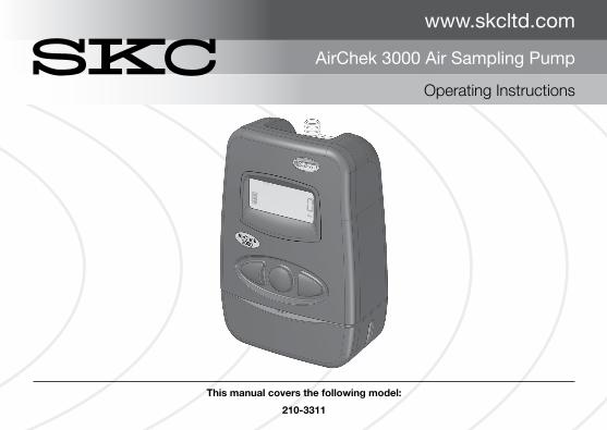
www.skcltd.com
AirChek 3000 Air Sampling Pump
Operating Instructions
This manual covers the following model:
210-3311
Page 2 210-3311M Issue I www.skcltd.com
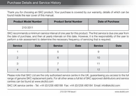
Purchase Details and Service History
Thank you for choosing an SKC product. Your purchase is covered by our warranty, details of which can be found inside the rear cover of this manual.
Product Model Number Product Serial Number Date of Purchase
210-3311
SKC recommends a minimum service interval of one year for this product. The first service is due one year from the date of purchase, and then at yearly intervals on this date. However, it is the responsibility of the user to perform a risk assessment to determine the necessary frequency of servicing that is required.
Service Date Service Date Service Date
1 5 9
2 6 10
3 7 11
4 8 12
Please note that SKC Ltd are the only authorised service centre in the UK, guaranteeing you access to the full range of genuine SKC replacement parts. For all other areas a full list of SKC approved distributors and service centres can be found at www.skcltd.com
SKC UK service centre - Tel: +44 (0)1258 480188 Fax: +44 (0)1258 480184 Email: [email protected]
www.skcltd.com 210-3311M Issue I Page 1
Blank Page

Page 2 210-3311M Issue I www.skcltd.com
Contents
Intrinsic Safety Information .............................................................................................................................4
Specifications ................................................................................................................................................6
General Information .....................................................................................................................................10
Diagram of the AirChek 3000 Pump ............................................................................................................12
AirChek 3000 Pump LCD Screen ................................................................................................................14
AirChek 3000 Pump Keypad .......................................................................................................................15
Getting Started ............................................................................................................................................16
1) Charging the Battery Pack ..............................................................................................................162) Battery Status Indicator ..................................................................................................................173) SLEEP Mode ..................................................................................................................................174) HOLD and RUN Modes ..................................................................................................................185) Pump Run LED Indicator ................................................................................................................186) Flow Fault .......................................................................................................................................187) Entering and Navigating the User Interface ......................................................................................19
Run Time Data Screens ...............................................................................................................................20
User Interface Level One ..............................................................................................................................22
1) Setting and Manual Calibration of the Pump Flow Rate ...................................................................222) Setting and Automatic Calibration of the Pump Flow Rate Using CalChek ......................................233) Full (Multiple Point) Flow Calibration Using CalChek ........................................................................26

www.skcltd.com 210-3311M Issue I Page 3
User Interface Level Two ..............................................................................................................................29
1) Changing the Display Units .............................................................................................................292) Setting the Clock Time ....................................................................................................................303) Setting a Sample Run Time ............................................................................................................314) Deleting a Sample Run Time ...........................................................................................................335) Setting a Delayed Start Time ...........................................................................................................346) Deleting a Delayed Start Time or DataTrac Program ........................................................................367) Resetting the Run Time Data ..........................................................................................................37
Low Flow Sampling .....................................................................................................................................38
General Troubleshooting ..............................................................................................................................40
CalChek Calibration Error Code Troubleshooting .........................................................................................42
Care of the Battery Pack ..............................................................................................................................44
AirChek 3000 Pump Components ...............................................................................................................46
AirChek 3000 Pump Replacement Parts ......................................................................................................48
AirChek 3000 Pump Accessories ................................................................................................................49
AirChek 3000 Pump DataTrac Software .......................................................................................................52
Intrinsic Safety Certification ..........................................................................................................................54
Warranty Information ...................................................................................................................................62
Contents
Page 4 210-3311M Issue I www.skcltd.com
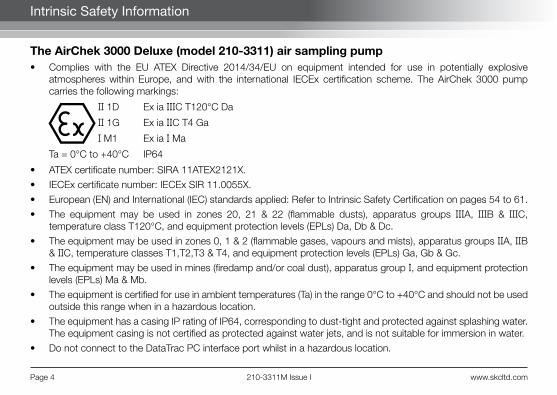
Intrinsic Safety Information
The AirChek 3000 Deluxe (model 210-3311) air sampling pump• Complies with the EU ATEX Directive 2014/34/EU on equipment intended for use in potentially explosive
atmospheres within Europe, and with the international IECEx certification scheme. The AirChek 3000 pump carries the following markings:
II 1D Ex ia IIIC T120°C Da
II 1G Ex ia IIC T4 Ga
I M1 Ex ia I Ma
Ta = 0°C to +40°C IP64
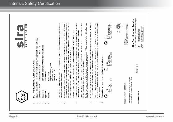
• ATEX certificate number: SIRA 11ATEX2121X.
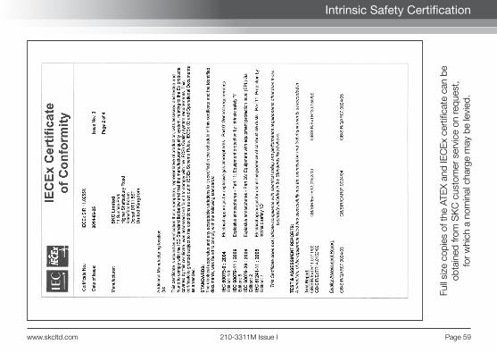
• IECEx certificate number: IECEx SIR 11.0055X.
• European (EN) and International (IEC) standards applied: Refer to Intrinsic Safety Certification on pages 54 to 61.
• The equipment may be used in zones 20, 21 & 22 (flammable dusts), apparatus groups IIIA, IIIB & IIIC, temperature class T120°C, and equipment protection levels (EPLs) Da, Db & Dc.
• The equipment may be used in zones 0, 1 & 2 (flammable gases, vapours and mists), apparatus groups IIA, IIB & IIC, temperature classes T1,T2,T3 & T4, and equipment protection levels (EPLs) Ga, Gb & Gc.
• The equipment may be used in mines (firedamp and/or coal dust), apparatus group I, and equipment protection levels (EPLs) Ma & Mb.
• The equipment is certified for use in ambient temperatures (Ta) in the range 0°C to +40°C and should not be used outside this range when in a hazardous location.
• The equipment has a casing IP rating of IP64, corresponding to dust-tight and protected against splashing water. The equipment casing is not certified as protected against water jets, and is not suitable for immersion in water.
• Do not connect to the DataTrac PC interface port whilst in a hazardous location.
www.skcltd.com 210-3311M Issue I Page 5
Intrinsic Safety Information
• The maximum input voltage, Um, at the DataTrac PC interface port is 6V. The safe area appratus that is to be connected to the DataTrac PC Interface port must be a Safety Extra Low Voltage (SELV) or Protective Extra Low Voltage (PELV) circuit, e.g. the serial (RS232) interface or USB interface of a PC.
• Do not charge the battery pack whilst in a hazardous location.
• Do not disconnect the battery pack from the pump whilst in a hazardous location. Fit the battery pack to the pump only when in a clean, dust free environment.
• Use only SKC approved chargers designated for this pump model.
• Do not subject the equipment to intense sunlight for long periods.
• The equipment has not been assessed as a safety related device (as referred to in Directive 2014/34/EU Annex II, clause 1.5).
• The recessed LCD screen window could potentially store an electrostatic charge if rubbed. Precautions must be taken to prevent the build up of electrostatic charge, particularly if the pump is used in a zone 0 location. Clean the LCD screen window only with a damp cloth.
• The equipment should not be used if damaged in a way that could invalidate intrinsic safety or the casing IP rating. Such damage might include cracking of the pump or battery pack enclosure and internal encapsulant such that internal components are exposed. It is the responsibility of the user to ensure that the pump is in an acceptable condition for use in hazardous locations.
• Substitution of components with non-SKC approved components may invalidate the intrinsic safety certification of the pump.
Important note about intrinsic safety
If you are unsure as to whether the air sampling pump you have purchased is suitable for your environment, check with your site manager or responsible person BEFORE USE that the intrinsic safety rating on the product meets your site re-quirements. SKC personnel are unable to recommend the appropriate safety rating for your site.
Page 6 210-3311M Issue I www.skcltd.com
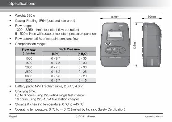
• Weight: 580 g
• Casing IP rating: IP64 (dust and rain proof)
• Flow range:1000 - 3250 ml/min (constant flow operation)5 - 500 ml/min with adapter (constant pressure operation)
• Flow control: ±5 % of set point constant flow
• Compensation range:
Flow rate(ml/min)
Back Pressure
(kPa) (“ H2O)
1000 0 - 8.7 0 - 351500 0 - 7.5 0 - 302000 0 - 7.5 0 - 302500 0 - 6.2 0 - 253000 0 - 5.0 0 - 203250 0 - 3.7 0 - 15
• Battery pack: NiMH rechargeable, 2.0 Ah, 4.8 V
• Charging time:Up to 3 hours using 223-240A single fast charger16 hours using 223-109A five station charger
• Storage & charging temperature: 0 °C to +45 °C
• Operating temperature: 0 °C to +40 °C (limited by Intrinsic Safety Certification)
90mm 59mm
133m
m
Specifications
www.skcltd.com 210-3311M Issue I Page 7
Specifications
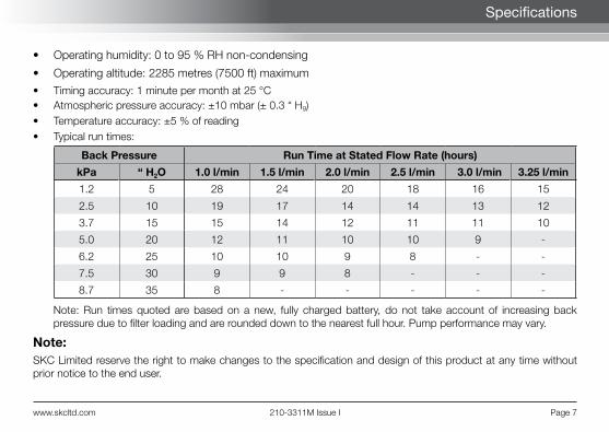
• Operating humidity: 0 to 95 % RH non-condensing
• Operating altitude: 2285 metres (7500 ft) maximum
• Timing accuracy: 1 minute per month at 25 °C• Atmospheric pressure accuracy: ±10 mbar (± 0.3 “ Hg)• Temperature accuracy: ±5 % of reading• Typical run times:
Back Pressure Run Time at Stated Flow Rate (hours)
kPa “ H2O 1.0 l/min 1.5 l/min 2.0 l/min 2.5 l/min 3.0 l/min 3.25 l/min
1.2 5 28 24 20 18 16 15
2.5 10 19 17 14 14 13 12
3.7 15 15 14 12 11 11 10
5.0 20 12 11 10 10 9 -
6.2 25 10 10 9 8 - -
7.5 30 9 9 8 - - -
8.7 35 8 - - - - -
Note: Run times quoted are based on a new, fully charged battery, do not take account of increasing back pressure due to filter loading and are rounded down to the nearest full hour. Pump performance may vary.
Note:SKC Limited reserve the right to make changes to the specification and design of this product at any time without prior notice to the end user.
Page 8 210-3311M Issue I www.skcltd.com
Specifications
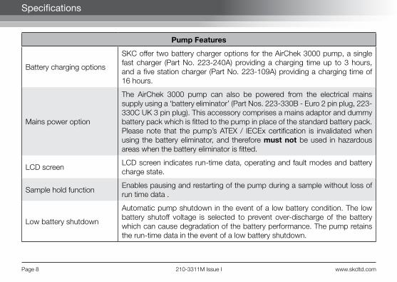
Pump Features
Battery charging options
SKC offer two battery charger options for the AirChek 3000 pump, a single fast charger (Part No. 223-240A) providing a charging time up to 3 hours, and a five station charger (Part No. 223-109A) providing a charging time of 16 hours.
Mains power option
The AirChek 3000 pump can also be powered from the electrical mains supply using a ‘battery eliminator’ (Part Nos. 223-330B - Euro 2 pin plug, 223-330C UK 3 pin plug). This accessory comprises a mains adaptor and dummy battery pack which is fitted to the pump in place of the standard battery pack. Please note that the pump’s ATEX / IECEx certification is invalidated when using the battery eliminator, and therefore must not be used in hazardous areas when the battery eliminator is fitted.
LCD screenLCD screen indicates run-time data, operating and fault modes and battery charge state.
Sample hold functionEnables pausing and restarting of the pump during a sample without loss of run time data .
Low battery shutdown
Automatic pump shutdown in the event of a low battery condition. The low battery shutoff voltage is selected to prevent over-discharge of the battery which can cause degradation of the battery performance. The pump retains the run-time data in the event of a low battery shutdown.

www.skcltd.com 210-3311M Issue I Page 9
Specifications
Pump Features
Flow fault function
Indicates flow fault due to obstructed tubing or excessive filter loading. Shuts the pump down and enters ‘HOLD’ mode if the condition persists for longer than 15 seconds. Automatically attempts to restart every five minutes (up to a maximum of 10 restarts), until the flow fault condition clears in which case normal running will resume.
Programmable run timeSample run time programmable in minutes, via keypad and LCD screen. Pump automatically shuts down at end of sample and retains run time data.
Programmable delayed start time
Sample start delay time programmable in hours and minutes, via keypad and LCD screen.
Particulate trapBuilt in replaceable filter to trap particles that would otherwise contaminate the pump mechanism.
Automatic air flow rate calibration
With optional chek-mate flowmeter and CalChek cable. Enables automatic calibration of the sample air flow rate to the required level.
PC ConnectivityWith optional DataTrac USB adapter cable and PC software. Enables programming of timed sample runs, delayed starts and intermittent sampling. Enables retrieval of pump run-time data and history to the PC.

Page 10 210-3311M Issue I www.skcltd.com
1) Pump Models
210-3311 Deluxe ATEX / IECEx certified pump with NiMH battery pack
2) Care of the AirChek 3000 Pump• Always use the correct SKC battery pack and battery chargers designated for the AirChek 3000 pump.• The battery pack charging socket is of the mini-USB type, however it is not a USB interface port and must not be
connected to a computer USB port. Damage to the battery pack and/or the computer may result.• Never run the pump long term without a tube or filter medium in place.• When carrying out sampling using long term colour change tubes always use a tandem tube holder with trap
tube. This will prevent the aggressive fumes generated by these tubes from entering and damaging the pump mechanism.
• When carrying out sampling using impingers always fit a trap between the impinger and pump inlet. This will prevent the possibility of the fluid used in the impinger from entering and damaging the pump mechanism. As a further precaution always ensure that the pump flow rate is set to below 1 litre/min before connecting the trap and impinger to the pump inlet.
• The AirChek 3000 pump case is IP64 rated, and therefore must not be used where it may be subjected to water jets or complete immersion in water. The pump can be used where it may be subjected to rain or splashing water, but care must be taken to ensure that water cannot enter the pump air inlet port.
• The AirChek 3000 pump is fitted with a particulate filter which is easy to replace. Simply unscrew the inlet filter cover (use a 13mm A/F spanner to loosen the cover if required), remove the O ring and lift out the filter. Fit the new filter, taking care not to crease it when inserting, fit the O ring and screw on the inlet filter cover hand tight only. For general maintenance replace the filter every 2 - 3 months or if it appears dirty. New filters are white in colour (order Part No. P40011).
Warning - Failure to follow these guidelines will void the product warranty.
General Information

www.skcltd.com 210-3311M Issue I Page 11
General Information
3) Non ATEX / IECEx Certified Variants of the AirChek 3000 Pump The AirChek 3000 pump is also produced as a variant model which is certified for intrinsic safety for use in Australia and New Zealand to the ANZEx certification scheme, and these pumps are therefore not suitable for use in potentially explosive atmospheres in Europe where ATEX certification is mandatory.
Pump components vary between the ANZEx and ATEX / IECEx certified variants, therefore components must not be interchanged between these pumps. If in any doubt please contact SKC Ltd customer services for advice.
4) Sampling MethodsThis instruction manual provides the necessary information to set up and operate the AirChek 3000 pump. For more detailed information on specific sampling methods please refer to SKC’s Step-By-Step Guide to Air Sampling (Part No. 224-G1). To obtain a free copy please contact SKC Ltd customer services on +44 (0) 1258 480188 or download at www.skcltd.com.
5) The WEEE DirectiveThis product is marked with the crossed out wheelie bin symbol, which identifies that it falls within the scope of the EC Directive 2002/96/EC on waste electrical and electronic equipment (WEEE). At the end of it’s useful life, this product must be disposed of in an environmentally sound way as detailed in the Directive. Note that the battery pack must be separated from the pump and disposed of as detailed in the Batteries Directive (see below). Please contact your local distributor or SKC Ltd for further details on how to comply with the requirements of the WEEE Directive. SKC Ltd’s producer registration number is WEE/KH0054TQ.
6) The Batteries DirectiveThe NiMH battery pack supplied with this pump and any spare battery packs purchased for it, fall within the scope of the EC Directive 2006/66/EC on batteries and accumulators and waste batteries and accumulators. At the end of the battery pack’s life it must be disposed of in an environmentally sound way as detailed in the Directive. Please contact your local distributor or SKC Ltd for further details on how to comply with the requirements of the Batteries Directive. SKC Ltd’s batteries producer registration number is BPRN00454.

Page 12 210-3311M Issue I www.skcltd.com
Air Inlet Port Air Inlet Port
Belt ClipKeypad
LCD Screen
DataTrac PCInterface Port
Cover
InletParticulate
Filter
Battery Pack Charging SocketCover
Pump Run LED
Diagram of the AirChek 3000 Pump
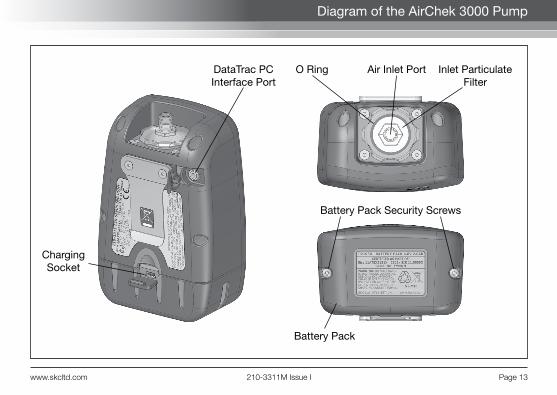
www.skcltd.com 210-3311M Issue I Page 13
Diagram of the AirChek 3000 Pump
Air Inlet Port
ChargingSocket
DataTrac PCInterface Port
Inlet ParticulateFilter
Battery Pack
Battery Pack Security Screws
O Ring

Page 14 210-3311M Issue I www.skcltd.com
AirChek 3000 Pump LCD Screen
Operating Indicators
Display Units
NumeralsFlow Fault Indicator
Battery Charge Status
Operating Indicators
PROG Active when a sample program is loaded into the pump memory.
HOLD Flashes when the pump is in HOLD mode.
ADJ Flashes when adjusting the pump flow rate during flow calibration.
FLOW Active when the pump LCD screen displays the flow rate.
VOL Active when the pump LCD screen displays the volume of air sampled.
SET Flashes when setting the pump flow rate, display units, clock time and delayed start time.
Display Units
°C or °F Sample air temperature in degrees Centigrade or Farenheit.
ins, mm or m Atmospheric pressure in inches of mercury, millimetres of mercury or millibars.
mL/min Pump flow rate in millilitres per minute.
mL or L Total volume of air sampled in millilitres or litres since last reset.
min Run time in minutes since last reset.
am and/or pm Time of day in hours and minutes (12 or 24 hour clock).

www.skcltd.com 210-3311M Issue I Page 15
AirChek 3000 Pump Keypad
Scroll Button
Toggle / Decrease ButtonToggle / Increase Button
Keypad Operation
Scrolls through run time data in RUN and HOLD modes. Scrolls through sampling parameters and display options when navigating the User Interface.
Toggles between options and increases values when navigating the User Interface.
Toggles between options and decreases values when navigating the User Interface.
or or To wake the pump from SLEEP mode and activate the LCD screen press any of the three buttons.
[ ] Press buttons simultaneously. Switches between HOLD and RUN modes. When navigating the User Interface selects or enters the displayed item.
Security code that must be pressed in sequence within 10 seconds after changing operating mode (from HOLD to RUN mode, or RUN to HOLD mode) to enter the User Interface. If the 10 second time limit is exceeded, the pump will remain in its current (HOLD or RUN) mode.
Page 16 210-3311M Issue I www.skcltd.com
Getting Started
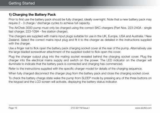
1) Charging the Battery PackPrior to first use the battery pack should be fully charged, ideally overnight. Note that a new battery pack may require 2 - 3 charge / discharge cycles to achieve full capacity.
The AirChek 3000 pump must only be charged using the correct SKC chargers (Part Nos. 223-240A - single fast charger, 223-109A - five station charger).
The chargers are supplied with mains input plugs suitable for use in the UK, Europe, USA and Australia / New Zealand. Select the correct mains input plug and fit it to the charger as detailed in the instructions supplied with the charger.
Use a finger nail to flick open the battery pack charging socket cover at the rear of the pump. Alternatively use the large bladed screwdriver attachment of the supplied toolkit to flick open the cover.
Plug the charger output plug into the mating socket revealed behind the charging socket cover. Plug the charger into the electrical mains supply and switch on the power. The LED indicator on the charger will illuminate to indicate that the battery pack is connected and charging has commenced.
Refer to the instructions supplied with the specific charger model for details of the charging sequence.
When fully charged disconnect the charger plug from the battery pack and close the charging socket cover.
To check the battery charge state wake the pump from SLEEP mode by pressing any of the three buttons on the keypad and the LCD screen will activate, displaying the battery status indicator.

www.skcltd.com 210-3311M Issue I Page 17
Getting Started
2) Battery Status IndicatorThe battery status indicator on the pump LCD screen shows the current battery charge level:
Fully charged. Three bars displayed from approximately 100% to 75% capacity. Note: It is strongly recommended to ensure that the battery is fully charged before starting a sample run.
Two bars displayed from approximately 75% to 25% capacity.
One bar displayed below approximately 25% capacity.
Low battery. No bars and flashing outline indicates low battery. Pump automatically switches to HOLD mode, and then SLEEP mode within 10 seconds.
Note: When the pump stops due to a low battery and is left to stand for a period of time, one bar may appear on the battery status indicator when the LCD screen is activated. This false “recovery” will fall quickly if the pump is operated without recharging it. RECHARGE THE PUMP BEFORE SAMPLING.
3) SLEEP ModeIf the pump is left in HOLD mode for longer than five minutes the pump will automatically set itself to a low power SLEEP mode, with the LCD screen switched off. To wake the pump from SLEEP mode simply press any of the three buttons and the pump LCD screen will activate and display the last four digits of the pump serial number followed by the internal software version number before switching to HOLD mode.

Page 18 210-3311M Issue I www.skcltd.com
Getting Started
The pump will also automatically wake from SLEEP mode when the battery charger is connected.
4) HOLD and RUN ModesTo switch from HOLD mode to RUN mode press [ ]. The pump will start to run and the run time data will be updated continuously in memory. The LCD screen will display the real-time run time data. Press the button to scroll through the run time data. The sample run time and sample air volume will continue to accumulate unless reset - refer User Interface Level Two 7) on page 37.
To switch from RUN mode to HOLD mode press [ ]. The pump will stop and retain the run-time data in memory. The temperature, atmospheric pressure and clock time readings remain active in HOLD mode, and can be displayed on the LCD screen, along with the accumulated sample run time and sample air volume by scrolling through the run time data screens by pressing the button.
5) Pump Run LED IndicatorWhen the pump is in RUN mode the blue pump run LED indicator will flash on and off to indicate that the pump is running.
6) Flow FaultIf pump operation is interrupted due to blocked or restricted air flow, the flow fault indicator will flash. If the flow fault persists for 15 seconds the pump will stop and switch to HOLD mode, with the flow fault indicator on continuously. The pump will then wait 5 minutes before automatically switching to RUN mode to continue sampling. If the flow remains restricted the pump will return to HOLD mode, and attempt to restart every 5 minutes up to a maximum of 10 restarts. The maximum number of restart attempts can be changed using a PC and the optional DataTrac Interface and Software.
The accumulated sample run time and sample air volume readings are retained but not updated whilst the pump is in flow fault.

www.skcltd.com 210-3311M Issue I Page 19
Getting Started
7) Entering and Navigating the User InterfaceThe AirChek 3000 pump User Interface features two security code protected levels:
• Level One - Accessed from RUN mode, allows the user to change the air flow rate, adjust the air flow rate to a calibrated air flowmeter, and calibrate the pump automatically using the CalChek feature.
To enter the Level One User Interface, with the pump in HOLD mode, press [ ] to switch to RUN mode and within 10 seconds press the security code sequence .
• Level Two - Accessed from HOLD mode, allows the user to change the display units for the temperature and atmospheric pressure, set a sample run time, select 12 or 24 hour clock display, set a delayed start time, set the clock time, and clear the accumulated run time data.
To enter the Level Two User Interface, with the pump in RUN mode, press [ ] to switch to HOLD mode and within 10 seconds press the security code sequence .
To navigate the User Interface, press the button to scroll through the different parameters on the LCD screen.
To exit the User Interface, press the button to scroll through the different parameter screens until the LCD screen displays ‘End’. Press [ ] to exit. Any changes made to the parameters will be saved and the pump will continue in its current (HOLD or RUN) mode.
The Level Two User Interface also includes the option to exit without saving changes to the parameters. Press the button to scroll through the different parameter screens until the LCD screen displays “ESC”. Press [ ] to exit without saving.
Page 20 210-3311M Issue I www.skcltd.com
Run Time Data Screens
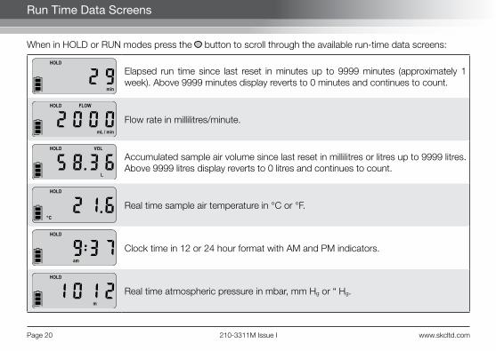
When in HOLD or RUN modes press the button to scroll through the available run-time data screens:
Elapsed run time since last reset in minutes up to 9999 minutes (approximately 1 week). Above 9999 minutes display reverts to 0 minutes and continues to count.
Flow rate in millilitres/minute.
Accumulated sample air volume since last reset in millilitres or litres up to 9999 litres. Above 9999 litres display reverts to 0 litres and continues to count.
Real time sample air temperature in °C or °F.
Clock time in 12 or 24 hour format with AM and PM indicators.
Real time atmospheric pressure in mbar, mm Hg or “ Hg.
www.skcltd.com 210-3311M Issue I Page 21
Run Time Data Screens
The flow rate displayed on the pump LCD screen is the flow rate to which the pump has been calibrated. To maintain the flow rate as displayed, the pump automatically adjusts its operation during sampling for changes in temperature and atmospheric pressure that may differ from the temperature and atmospheric pressure present at the time of calibration. The flow rate display does not change from the calibrated flow rate. The pump will flow fault if it is unable to maintain the calibrated flow rate to within ±5 %.
The accumulated sample air volume displayed on the pump LCD screen is ”corrected” in that it is the result of a continuous calculation of corrected flow rate multiplied by sample time.
Page 22 210-3311M Issue I www.skcltd.com
User Interface Level One
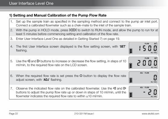
1) Setting and Manual Calibration of the Pump Flow Rate
1. Set up the sample train as specified in the sampling method and connect to the pump air inlet port. Connect a calibrated flowmeter such as a chek-mate to the inlet of the sample train.
2. With the pump in HOLD mode, press [ ] to switch to RUN mode, and allow the pump to run for at least 5 minutes before commencing setting and calibration of the flow rate.
3. Enter User Interface Level One as detailed in Getting Started 7) on page 19.
4. The first User Interface screen displayed is the flow setting screen, with ‘SET’ flashing.
5. Use the and buttons to increase or decrease the flow setting, in steps of 10 ml/min, to the required flow rate on the LCD screen.
6. When the required flow rate is set press the button to display the flow rate adjust screen, with ‘ADJ’ flashing.
7. Observe the indicated flow rate on the calibrated flowmeter. Use the and buttons to adjust the pump flow rate up or down in steps of 10 ml/min, until the flowmeter indicates the required flow rate to within ±10 ml/min.

www.skcltd.com 210-3311M Issue I Page 23
User Interface Level One
8. Press the button twice to display the ‘End’ screen.
9. Press [ ] to exit to RUN mode. The pump will now maintain the calibrated flow rate to within ±5%.
10. Press [ ] to switch to HOLD mode. Before commencing sampling it is recommended to reset the accumulated run time data. Refer to User Interface Level Two 7) on page 37.
2) Setting and Automatic Calibration of the Pump Flow Rate Using CalChekThe CalChek communication cable provides direct communication between the AirChek 3000 pump and a chek-mate model 375-0550 flowmeter. This communication enables automatic adjustment and calibration of the pump flow rate. Refer to the Accessories Table on pages 49 - 51 for chek-mate and CalChek accessory part numbers.
Note: Do not perform a calibration until the pump has remained at ambient temperature for at least 2 hours.
1. Set up the sample train as specified in the sampling method and connect to the pump air inlet port. Connect the chek-mate flowmeter air outlet port to the inlet of the sample train. Connect the CalChek communication cable between the CalChek interface socket on the right hand side of the chek-mate flowmeter and the PC interface socket on the rear of the AirChek 3000 pump.
Page 24 210-3311M Issue I www.skcltd.com
User Interface Level One
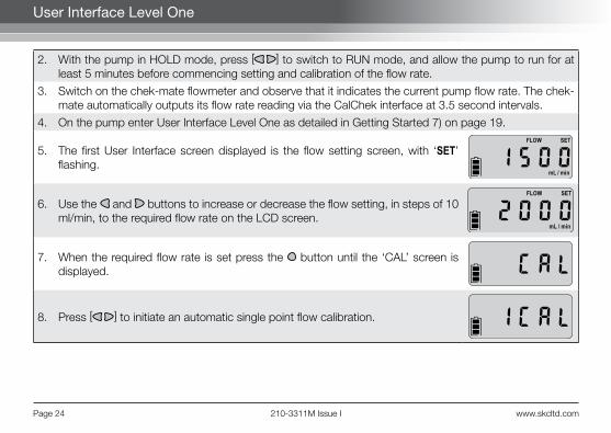
2. With the pump in HOLD mode, press [ ] to switch to RUN mode, and allow the pump to run for at least 5 minutes before commencing setting and calibration of the flow rate.
3. Switch on the chek-mate flowmeter and observe that it indicates the current pump flow rate. The chek-mate automatically outputs its flow rate reading via the CalChek interface at 3.5 second intervals.
4. On the pump enter User Interface Level One as detailed in Getting Started 7) on page 19.
5. The first User Interface screen displayed is the flow setting screen, with ‘SET’ flashing.
6. Use the and buttons to increase or decrease the flow setting, in steps of 10 ml/min, to the required flow rate on the LCD screen.
7. When the required flow rate is set press the button until the ‘CAL’ screen is displayed.
8. Press [ ] to initiate an automatic single point flow calibration.

www.skcltd.com 210-3311M Issue I Page 25
9. The pump will read in the flow rate values from the chek-mate via the CalChek interface for a short period of time to ensure that the flow is stable and the pump LCD screen will then briefly display a pre-calibration flow rate.
10. The pump will then automatically adjust the flow rate to the required value using the “ADJ FLOW” setting, and after reading the new flow rate in from the chek-mate the LCD screen will briefly display a post-calibration flow rate.
11. At the end of a successful single point calibration the pump will automatically display the ‘End’ screen.
12. Press [ ] to exit to RUN mode. The pump will now maintain the calibrated flow rate to within ±5%.
13. Press [ ] to switch to HOLD mode. The calibration data is written into the pump memory when the pump switches to SLEEP mode, therefore leave the pump in HOLD mode for five minutes after which it will switch to SLEEP mode. Before commencing sampling it is recommended to reset the accumulated run time data. Refer to User Interface Level Two 7) on page 37.
14. If a problem was encountered during the single point calibration, an error code will be displayed. Refer to the CalChek Error Code Table on pages 42 and 43. Press the button to clear the error code screen and revert to RUN mode.
User Interface Level One
Page 26 210-3311M Issue I www.skcltd.com
User Interface Level One
Both the pre-calibration and post-calibration flow rates with the time and date are recorded in the pump history memory and can be accessed using the optional DataTrac Interface and Software and a PC.The single point calibration function can also be used to provide an automatic post sampling calibration check. However, as the function may adjust the flow rate, this is only recommended if the DataTrac Interface and Software are available. Otherwise a manual post sampling calibration check is recommended.
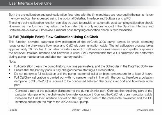
3) Full (Multiple Point) Flow Calibration Using CalChekThis function provides automatic flow calibration of the AirChek 3000 pump across its whole operating range using the chek-mate flowmeter and CalChek communication cable. The full calibration process takes approximately 10 minutes. It can also provide a record of calibration for maintenance and quality purposes if the optional DataTrac Interface and Software is used. SKC recommends that a full calibration be performed during pump maintenance and after non-factory repairs.
Note:
• Full calibration clears the pump history, run time parameters, and the Scheduler in the DataTrac Software.• Ensure that the battery pack is fully charged before starting a full calibration.• Do not perform a full calibration until the pump has remained at ambient temperature for at least 2 hours.• Full CalChek calibration is carried out with no sample media in line with the pump, therefore a pulsation
dampener (P/N 375-200) is required to be connected between the pump inlet port and flowmeter outlet port.
1. Connect a port of the pulsation dampener to the pump air inlet port. Connect the remaining port of the pulsation dampener to the chek-mate flowmeter outlet port. Connect the CalChek communication cable between the CalChek interface socket on the right hand side of the chek-mate flowmeter and the PC interface socket on the rear of the AirChek 3000 pump.
www.skcltd.com 210-3311M Issue I Page 27
User Interface Level One
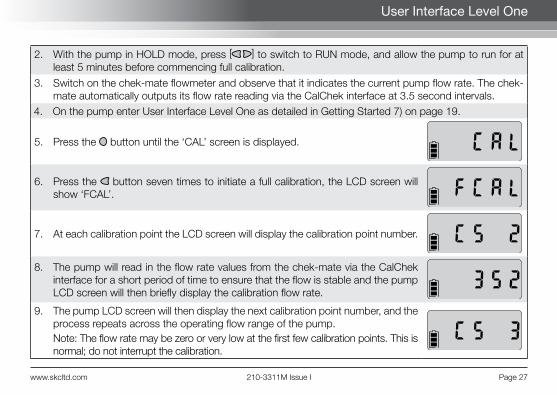
2. With the pump in HOLD mode, press [ ] to switch to RUN mode, and allow the pump to run for at least 5 minutes before commencing full calibration.
3. Switch on the chek-mate flowmeter and observe that it indicates the current pump flow rate. The chek-mate automatically outputs its flow rate reading via the CalChek interface at 3.5 second intervals.
4. On the pump enter User Interface Level One as detailed in Getting Started 7) on page 19.
5. Press the button until the ‘CAL’ screen is displayed.
6. Press the button seven times to initiate a full calibration, the LCD screen will show ‘FCAL’.
7. At each calibration point the LCD screen will display the calibration point number.
8. The pump will read in the flow rate values from the chek-mate via the CalChek interface for a short period of time to ensure that the flow is stable and the pump LCD screen will then briefly display the calibration flow rate.
9. The pump LCD screen will then display the next calibration point number, and the process repeats across the operating flow range of the pump.Note: The flow rate may be zero or very low at the first few calibration points. This is normal; do not interrupt the calibration.
Page 28 210-3311M Issue I www.skcltd.com
User Interface Level One
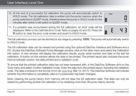
10. At the end of a successful full calibration the pump will automatically switch to HOLD mode. The full calibration data is written into the pump memory when the pump switches to SLEEP mode, therefore leave the pump in HOLD mode for five minutes after which it will switch to SLEEP mode.
11. If a problem was encountered during the full calibration, an error code will be displayed. Refer to the CalChek Error Code Table on pages 42 and 43. Press the
button to clear the error code screen and revert to HOLD mode.
The full calibration process can be aborted at any stage by pressing [ ]. The pump will automatically switch to HOLD mode.
The full calibration data can be viewed and printed using the optional DataTrac Interface and Software and a PC. Access the DataTrac Software Pump Manager window, click on the View menu and select the Calibration Info option. A new window will display the calibration results, pump serial number and date of the last full calibration. A button on this window allows the data to be printed. The printed report also includes the pump internal software version, the date printed and a validation code.
To ensure that the printed calibration data has not been tampered with, in the DataTrac Software click on the Tools menu and select Confirm Validation Code. Enter the data from the printed report, including the validation code. The date is entered in the format mmm dd, yyyy (e.g. Mar 12, 2011). The DataTrac Software will indicate whether the information is completely valid or if a parameter has been changed.
Note: Clearing the pump history from memory will not clear the full calibration data. This data can only be cleared by performing another full calibration or by obtaining more than 36 pump history records.

www.skcltd.com 210-3311M Issue I Page 29
User Interface Level Two
1) Changing the Display Units
1. On the pump enter User Interface Level Two as detailed in Getting Started 7) on page 19.
2. Press the button until the temperature units setting screen is displayed with ‘SET’ and the current display units flashing. The display shows the current air temperature.
3. Use the and buttons to toggle between the ‘°F’ and ‘°C’ temperature units options.
4. Press the button until the atmospheric pressure units setting screen is displayed with ‘SET’ and the current display units flashing. The display shows the current atmospheric pressure.
5. Use the and buttons to toggle between the ‘ins’ (“ Hg), ‘m’ (mbar) and ‘mm’ (mm Hg) atmospheric pressure units options.
6. To save the new display units settings, press the button until the ‘End’ screen is displayed. Press [ ] to save the settings and switch to HOLD mode.
Page 30 210-3311M Issue I www.skcltd.com
User Interface Level Two
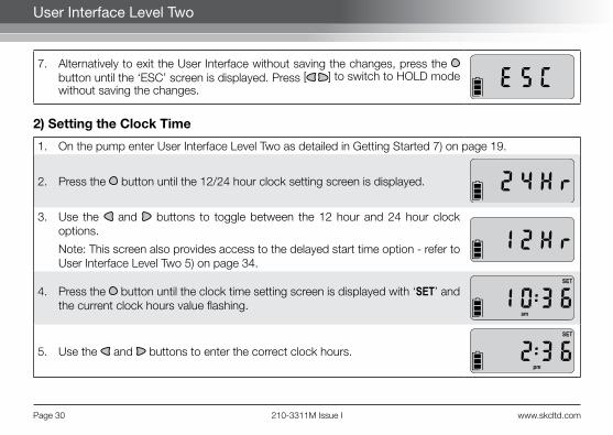
7. Alternatively to exit the User Interface without saving the changes, press the button until the ‘ESC’ screen is displayed. Press [ ] to switch to HOLD mode without saving the changes.
2) Setting the Clock Time
1. On the pump enter User Interface Level Two as detailed in Getting Started 7) on page 19.
2. Press the button until the 12/24 hour clock setting screen is displayed.
3. Use the and buttons to toggle between the 12 hour and 24 hour clock options.
Note: This screen also provides access to the delayed start time option - refer to User Interface Level Two 5) on page 34.
4. Press the button until the clock time setting screen is displayed with ‘SET’ and the current clock hours value flashing.
5. Use the and buttons to enter the correct clock hours.
www.skcltd.com 210-3311M Issue I Page 31
User Interface Level Two
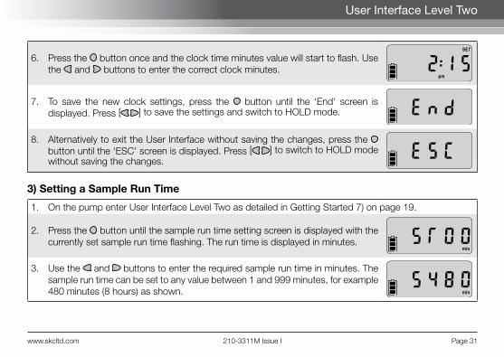
6. Press the button once and the clock time minutes value will start to flash. Use the and buttons to enter the correct clock minutes.
7. To save the new clock settings, press the button until the ‘End’ screen is displayed. Press [ ] to save the settings and switch to HOLD mode.
8. Alternatively to exit the User Interface without saving the changes, press the button until the ‘ESC’ screen is displayed. Press [ ] to switch to HOLD mode without saving the changes.
3) Setting a Sample Run Time
1. On the pump enter User Interface Level Two as detailed in Getting Started 7) on page 19.
2. Press the button until the sample run time setting screen is displayed with the currently set sample run time flashing. The run time is displayed in minutes.
3. Use the and buttons to enter the required sample run time in minutes. The sample run time can be set to any value between 1 and 999 minutes, for example 480 minutes (8 hours) as shown.

Page 32 210-3311M Issue I www.skcltd.com
4. To save the new sample run time setting, press the button until the ‘End’ screen is displayed. Press [ ] to save the setting and switch to HOLD mode.
5. Alternatively to exit the User Interface without saving the changes, press the button until the ‘ESC’ screen is displayed. Press [ ] to switch to HOLD mode without saving the changes.
6. Having successfully saved a sample run time and switched to HOLD mode, the elapsed run time screen will show a flashing ‘S’ and the programmed sample run time in minutes.
7. Press [ ] to switch to RUN mode and start the sampling operation. The sample run time will count down in one minute steps.
8. At the end of the sample run time the pump will automatically switch to HOLD mode, and the display will revert to showing the set sample run time.
Note:
• After cancelling a previously set sample run time, the elapsed run time screen will display the total sample run time since the run time data was last reset.
• If a sample run time has been set on the pump, a DataTrac program cannot be entered into the pump
User Interface Level Two

www.skcltd.com 210-3311M Issue I Page 33
User Interface Level Two
memory without deleting the sample run time first. Likewise, if a DataTrac program is present in the pump memory, the sample run time setting in the User Interface cannot be selected until the DataTrac program is deleted - refer to User Interface Level Two 6) on page 36.
• When entering a DataTrac program using the optional DataTrac Interface and Software and a PC, it is possible to enter a sample run time of up 43,200 minutes (30 days). When a DataTrac program is present in the pump memory the LCD screen will display the ‘PROG’ icon. The elapsed run time screen will display the elapsed run time rather than counting down the sample run time as with a sample run time set on the pump.
4) Deleting a Sample Run Time
1. To delete a previously set sample run time, enter User Interface Level Two as detailed in Getting Started 7) on page 19.
2. Press the button until the sample run time setting screen is displayed with the currently set sample run time flashing.
3. To delete the sample run time use the button to reduce the sample run time setting to zero.
4. To save the zero sample run time setting, press the button until the ‘End’ screen is displayed. Press [ ] to save the setting and switch to HOLD mode.

Page 34 210-3311M Issue I www.skcltd.com
5) Setting a Delayed Start TimeThe delayed start time is the 12 hour clock time at which the pump will automatically switch from HOLD mode to RUN mode and commence sampling. The delayed start time set has no AM or PM designation, and the actual start time will be the next occurence of this time in the 12 hour clock, either in the AM or PM. The delayed start time must be set in conjunction with a sample run time.
1. On the pump enter User Interface Level Two as detailed in Getting Started 7) on page 19.
2. Enter a sample run time as detailed in User Interface Level Two 3) on page 31. This is required to set a delayed start time.
3. Press the button until the 12/24 hour clock setting screen is displayed.
4. Use the and buttons to select the delayed start option, with ‘dELA’ flashing on the LCD screen.
5. Press the button once to display the delayed start time screen, with ‘SET’ and the current delayed start time hours value flashing.
6. Use the and buttons to enter the required delayed start time hours value.
User Interface Level Two
www.skcltd.com 210-3311M Issue I Page 35
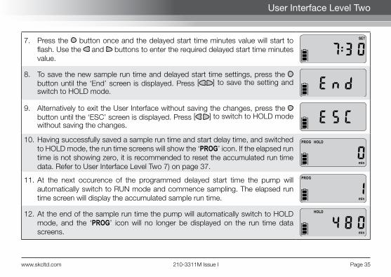
7. Press the button once and the delayed start time minutes value will start to flash. Use the and buttons to enter the required delayed start time minutes value.
8. To save the new sample run time and delayed start time settings, press the button until the ‘End’ screen is displayed. Press [ ] to save the setting and switch to HOLD mode.
9. Alternatively to exit the User Interface without saving the changes, press the button until the ‘ESC’ screen is displayed. Press [ ] to switch to HOLD mode without saving the changes.
10. Having successfully saved a sample run time and start delay time, and switched to HOLD mode, the run time screens will show the ‘PROG’ icon. If the elapsed run time is not showing zero, it is recommended to reset the accumulated run time data. Refer to User Interface Level Two 7) on page 37.
11. At the next occurence of the programmed delayed start time the pump will automatically switch to RUN mode and commence sampling. The elapsed run time screen will display the accumulated sample run time.
12. At the end of the sample run time the pump will automatically switch to HOLD mode, and the ‘PROG’ icon will no longer be displayed on the run time data screens.
User Interface Level Two

Page 36 210-3311M Issue I www.skcltd.com
User Interface Level Two
6) Deleting a Delayed Start Time or DataTrac ProgramThe following procedure is used to delete a delayed start time setting. If a DataTrac sampling program has been entered into the pump memory using the optional DataTrac Interface and Software and a PC, the same procedure is used to delete the DataTrac program from the pump memory.
1. Enter User Interface Level Two as detailed in Getting Started 7) on page 19.
2. Press the button until the flashing ‘Off’ screen is displayed.
Note: This screen is only displayed if a delayed start time is set or a DataTrac program is present in the pump memory.
3. To delete the sample run time or DataTrac program press [ ]. The 12/24 hour clock setting screen will be displayed.
4. Press the button until the ‘End’ screen is displayed.
5. Press [ ] to save the setting and switch to HOLD mode. The ‘PROG’ icon will no longer be displayed on the run time data screens.

www.skcltd.com 210-3311M Issue I Page 37
User Interface Level Two
7) Resetting the Run Time Data
1. To reset the accumulated sample air volume and sample run time data, enter User Interface Level Two as detailed in Getting Started 7) on page 19.
2. Press the button until the flashing ‘CLr’ screen is displayed.
3. To reset the run time data press [ ]. The ‘ESC’ screen will be displayed.
4. Press the button until the ‘End’ screen is displayed.
5. Press [ ] to switch to HOLD mode.
Page 38 210-3311M Issue I www.skcltd.com
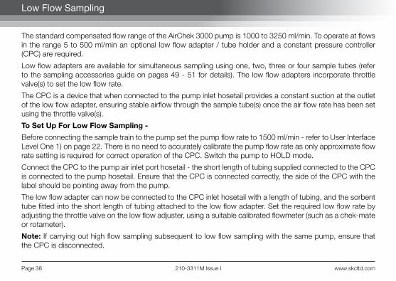
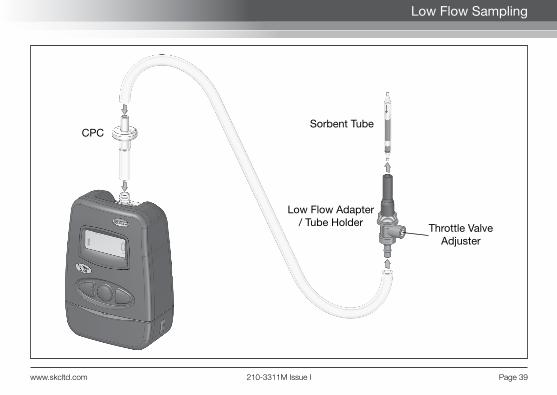
The standard compensated flow range of the AirChek 3000 pump is 1000 to 3250 ml/min. To operate at flows in the range 5 to 500 ml/min an optional low flow adapter / tube holder and a constant pressure controller (CPC) are required.
Low flow adapters are available for simultaneous sampling using one, two, three or four sample tubes (refer to the sampling accessories guide on pages 49 - 51 for details). The low flow adapters incorporate throttle valve(s) to set the low flow rate.
The CPC is a device that when connected to the pump inlet hosetail provides a constant suction at the outlet of the low flow adapter, ensuring stable airflow through the sample tube(s) once the air flow rate has been set using the throttle valve(s).
To Set Up For Low Flow Sampling -
Before connecting the sample train to the pump set the pump flow rate to 1500 ml/min - refer to User Interface Level One 1) on page 22. There is no need to accurately calibrate the pump flow rate as only approximate flow rate setting is required for correct operation of the CPC. Switch the pump to HOLD mode.
Connect the CPC to the pump air inlet port hosetail - the short length of tubing supplied connected to the CPC is connected to the pump hosetail. Ensure that the CPC is connected correctly, the side of the CPC with the label should be pointing away from the pump.
The low flow adapter can now be connected to the CPC inlet hosetail with a length of tubing, and the sorbent tube fitted into the short length of tubing attached to the low flow adapter. Set the required low flow rate by adjusting the throttle valve on the low flow adjuster, using a suitable calibrated flowmeter (such as a chek-mate or rotameter).
Note: If carrying out high flow sampling subsequent to low flow sampling with the same pump, ensure that the CPC is disconnected.
Low Flow Sampling
www.skcltd.com 210-3311M Issue I Page 39
Low Flow Sampling
CPC
Low Flow Adapter/ Tube Holder
Sorbent Tube
Throttle ValveAdjuster

Page 40 210-3311M Issue I www.skcltd.com
General Troubleshooting
Possible Fault Corrective Action
Battery pack will not charge
• Check the battery charger by trying it with a different battery pack. Replace the battery charger if required.
• Check the battery pack by connecting it to a known good battery charger. If the battery pack still will not charge replace the battery pack.
Pump will not operate• Check for faulty battery pack by trying a known good battery pack.
Replace the battery pack if required.
Pump flow faults continuously
• Sample media back pressure too high. Try a lower flow rate and/or a less restrictive sample media if the sampling method being used allows this.
• Pump particulate filter is blocked (appears black). Replace the particulate filter.
• Tubing blocked or crimped. Replace tubing.
Pump cannot achieve required flow rate
• Battery pack voltage low. Fully charge the battery pack.• Sample media back pressure too high. Try a lower flow rate and/or a
less restrictive sample media if the sampling method being used allows this.
• Inlet filter cover / hosetail not screwed on tightly enough. Ensure filter cover is tightly fitted.
• Pump mechanism leaking. Contact SKC Ltd customer services for assistance.
www.skcltd.com 210-3311M Issue I Page 41
General Troubleshooting
Possible Fault Corrective Action
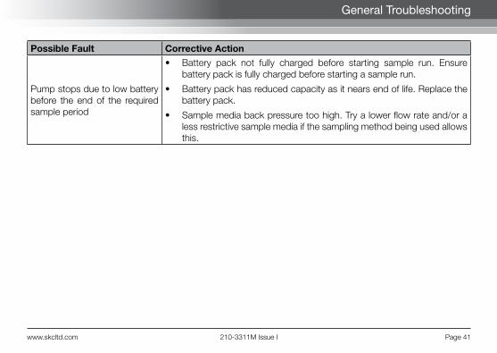
Pump stops due to low battery before the end of the required sample period
• Battery pack not fully charged before starting sample run. Ensure battery pack is fully charged before starting a sample run.
• Battery pack has reduced capacity as it nears end of life. Replace the battery pack.
• Sample media back pressure too high. Try a lower flow rate and/or a less restrictive sample media if the sampling method being used allows this.
Page 42 210-3311M Issue I www.skcltd.com
CalChek Calibration Error Code Troubleshooting
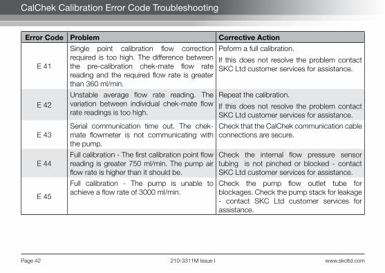
Error Code Problem Corrective Action
E 41
Single point calibration flow correction required is too high. The difference between the pre-calibration chek-mate flow rate reading and the required flow rate is greater than 360 ml/min.
Peform a full calibration.
If this does not resolve the problem contact SKC Ltd customer services for assistance.
E 42Unstable average flow rate reading. The variation between individual chek-mate flow rate readings is too high.
Repeat the calibration.
If this does not resolve the problem contact SKC Ltd customer services for assistance.
E 43Serial communication time out. The chek-mate flowmeter is not communicating with the pump.
Check that the CalChek communication cable connections are secure.
E 44Full calibration - The first calibration point flow reading is greater 750 ml/min. The pump air flow rate is higher than it should be.
Check the internal flow pressure sensor tubing is not pinched or blocked - contact SKC Ltd customer services for assistance.
E 45
Full calibration - The pump is unable to achieve a flow rate of 3000 ml/min.
Check the pump flow outlet tube for blockages. Check the pump stack for leakage - contact SKC Ltd customer services for assistance.

www.skcltd.com 210-3311M Issue I Page 43
CalChek Calibration Error Code Troubleshooting
Error Code Problem Corrective Action
E 46Full calibration - data analysis error. Repeat the full calibration.
If this does not resolve the problem contact SKC Ltd customer services for assistance.
E 47Full calibration - Battery charge level is too low. Less than two bars displayed on the battery status indicator.
Fully charge the battery before repeating the full calibration.
E 48Single point calibration - Pump could not achieve a successful calibration within 5 chek-mate flow readings.
Repeat the calibration.
If the problem repeats perform a full calibration.
Page 44 210-3311M Issue I www.skcltd.com
Care of the Battery Pack
Battery Charging• Charge battery pack fully before first use to ensure optimum performance.• Full battery capacity will be acheived after 2 to 3 full charge / full discharge cycles.• Use only SKC approved charger designated for this battery pack. Use of a non-SKC approved charger
may impair battery performance or even cause irrepairable damage, and will invalidate the battery pack warranty.
Battery Performance• Charging temperature - For optimum performance charge NiMH batteries between 0 and +45°C.• Do not overcharge - For optimum performance disconnect battery pack from charger after 24 hours.• Discharge temperature - For optimum performance discharge NiMH batteries between -10 and +45°C
(refer also to pump specifications on pages 6 and 7 for other limitations on operating temperature for intrinsically safe applications).
Battery Maintenance• Battery cycling during regular use - Available battery capacity may be reduced when battery is only partially
discharged during each use. To maintain optimum capacity during regular battery use, cycle battery once a month. To cycle battery, run pump until low battery shutdown occurs, then fully charge battery.
• Long term storage and highly infrequent use -1. Charge battery fully prior to long term storage. Disconnect battery pack from pump.2. Store in a cool, dry place at temperature between 0 and 30°C.3. Recharge battery at least once a year (or more frequently if stored at temperature above 30°C).4. Cycle battery 2 to 3 times after long term storage to restore optimum capacity.

www.skcltd.com 210-3311M Issue I Page 45
Care of the Battery Pack
Battery Testing1. Connect SKC approved charger to battery pack. If charger indicator LED illuminates, battery pack charger
input is ok. If charger LED does not illuminate, battery pack input fuse is blown - Replace battery pack.
2. Leave battery pack connected to charger to fully charge.
3. If pump does not function at all after full charge of battery pack, battery pack output fuse has blown, or battery cells have failed or are at end of life - Replace battery pack.
4. If pump functions after full charge of battery pack but gives significantly reduced run times before low battery shutdown, battery cells are failing or are at end of life - Replace battery pack.
Battery Replacement Refer to the pump component diagram on page 46. Unfasten the two security screws securing the battery pack to the pump using the supplied 2mm A/F hex screwdriver. Carefully pull the battery pack downwards to disconnect from the pump case.
Fit the replacement battery pack to the pump, taking care to ensure that the battery output connector engages with the socket in the base of the pump case. Secure the battery pack with the two security screws. Do not apply excessive force when tightening the screws. Charge the new battery pack fully before use.
Battery Disposal• The EC Battery Directive and equivalent legislation in other countries requires that all batteries and battery
packs are disposed of correctly at the end of their working life. This means that they must be collected and treated separately from other waste.
• Please ensure that any end-of-life SKC battery packs are collected and recycled or disposed of correctly.

Page 46 210-3311M Issue I www.skcltd.com
AirChek 3000 Pump Components
6
1
2
2
4
5
3
7

www.skcltd.com 210-3311M Issue I Page 47
AirChek 3000 Pump Components
8 9 10 11 8
12
Page 48 210-3311M Issue I www.skcltd.com
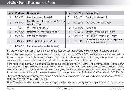
AirChek Pump Replacement Parts
Item Part No. Description Item Part No. Description
1 P210301 Inlet filter cover / hosetail 8 P21273 Stack gaskets (set of 2)
2 P210308Inlet filter and O ring (set of 3 filters and 3 O rings)
9 P210315 Top valve plate assembly
3 P40011 Inlet filter (pack of 50) 10 P22417G Pump body
4 P210303 DataTrac PC interface port cover 11 P210316 Bottom valve plate assembly
5 P210304 Belt clip and spacer 12 P22417HC Yoke and diaphragm assembly
6 P21030 Battery pack 4.8V 2.0Ah NiMH 13 P210302Toolkit for AirChek 3000 Pump (2mm A/F hex screwdriver)
7 P210305 Stack assembly (without motor)
SKC recommend that our air sampling pumps are regularly serviced by one of our Authorised Service Centres.
Due to the safety implications associated with the incorrect repair of ATEX / IECEx certified intrinsically safe products for use in potentially explosive atmospheres, it is our policy to only supply the complete range of replacement parts to our Authorised Service Centres who are trained in the service and repair of these products.
Care must be taken when dis-assembling the pump case to replace the above listed internal parts to ensure that the casing IP rating is maintained. Ensure that the sealing rib at the rear of the front case is in good condition and is reseated correctly into the recess around the front edge of the rear case when re-assembling. Do not apply excessive force when tightening the casing screws. If in any doubt contact your local distributor or SKC on +44 (0) 1258 480188.
The range of replacement parts listed above is available to all customers. If the required part is not listed, contact SKC customer care on +44 (0) 1258 480188.
Note: Table item numbers correspond to the ringed numbers shown in the figures on pages 46 and 47 of this manual.

www.skcltd.com 210-3311M Issue I Page 49
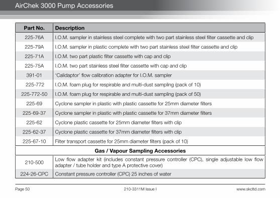
AirChek 3000 Pump Accessories
Part No. Description
Key Accessories
223-240A Single fast charger 100-240V ~ 50/60Hz supply with UK/EU/US/AUS mains plugs
223-109A Five station battery charger 100-240V ~ 50/60Hz supply with UK/EU/US/AUS mains plugs
223-330B Battery eliminator 230V ~ 50Hz supply with EU 2 pin mains plug
223-330C Battery eliminator 230V ~ 50Hz supply with UK 3 pin mains plug
224-88 Protective pouch in black
224-96A High visibility protective pouch in red
224-96C Noise reducing pouch in black
375-00205 chek-mate flowmeter 20 - 500 ml/min accuracy ±1% of reading (±2.5% at 20 - 50 ml/min)
375-0550 chek-mate flowmeter 0.5 - 5.0 l/min accuracy ±1% of reading (±2.5% at 0.5 to 0.75 l/min)
375-100 Pulsation dampener for use with 375-0550 chek-mate flowmeter
375-200 CalChek communication cable for use with 375-0550 chek-mate flowmeter
877-91K DataTrac software package including software CD, PC adapter and cable
Dust Sampling Accessories
225-70A I.O.M. sampler in plastic complete with two part plastic filter cassette and clip
Page 50 210-3311M Issue I www.skcltd.com
AirChek 3000 Pump Accessories
Part No. Description
225-76A I.O.M. sampler in stainless steel complete with two part stainless steel filter cassette and clip
225-79A I.O.M. sampler in plastic complete with two part stainless steel filter cassette and clip
225-71A I.O.M. two part plastic filter cassette with cap and clip
225-75A I.O.M. two part stainless steel filter cassette with cap and clip
391-01 ‘Calidaptor’ flow calibration adapter for I.O.M. sampler
225-772 I.O.M. foam plug for respirable and multi-dust sampling (pack of 10)
225-772-50 I.O.M. foam plug for respirable and multi-dust sampling (pack of 50)
225-69 Cyclone sampler in plastic with plastic cassette for 25mm diameter filters
225-69-37 Cyclone sampler in plastic with plastic cassette for 37mm diameter filters
225-62 Cyclone plastic cassette for 25mm diameter filters with clip
225-62-37 Cyclone plastic cassette for 37mm diameter filters with clip
225-67-10 Filter transport cassette for 25mm diameter filters (pack of 10)
Gas / Vapour Sampling Accessories
210-500Low flow adapter kit (includes constant pressure controller (CPC), single adjustable low flow adapter / tube holder and type A protective cover)
224-26-CPC Constant pressure controller (CPC) 25 inches of water
www.skcltd.com 210-3311M Issue I Page 51
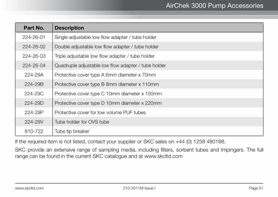
AirChek 3000 Pump Accessories
Part No. Description
224-26-01 Single adjustable low flow adapter / tube holder
224-26-02 Double adjustable low flow adapter / tube holder
224-26-03 Triple adjustable low flow adapter / tube holder
224-26-04 Quadruple adjustable low flow adapter / tube holder
224-29A Protective cover type A 6mm diameter x 70mm
224-29B Protective cover type B 8mm diameter x 110mm
224-29C Protective cover type C 10mm diameter x 150mm
224-29D Protective cover type D 10mm diameter x 220mm
224-29P Protective cover for low volume PUF tubes
224-29V Tube holder for OVS tube
810-722 Tube tip breaker
If the required item is not listed, contact your supplier or SKC sales on +44 (0) 1258 480188.
SKC provide an extensive range of sampling media, including filters, sorbent tubes and impingers. The full range can be found in the current SKC catalogue and at www.skcltd.com

Page 52 210-3311M Issue I www.skcltd.com
AirChek 3000 Pump DataTrac Software
With the optional DataTrac Software accessory, the AirChek 3000 pump is programmable using a PC. DataTrac simplifies chain-of-custody reporting by allowing users the option of programming a complete running sequence, delayed start, timed stop, and intermittent sampling, all at different flow rates. Time and sample volume are continuously updated in memory. There is no need to perform lengthy calculations; DataTrac does it for you. The advanced information retrieval system is specifically designed to store data and provide chain-of-custody information. Fault features allow storage of historical data in memory that can be retrieved days after shutdown as long as the battery pack is not completely discharged. The full DataTrac user’s manual is included on the software CDROM.
Features• Program a sampling operation from a
PC.• Calibrate the AirChek 3000 pump’s flow
rate to a primary standard.• Display the operating mode including
flow rate, temperature, run-time, and battery status.
• Create and save an AirChek 3000 program without the pump being connected to a PC.
• Program up to ten sampling sequences, each with different flow rates.

www.skcltd.com 210-3311M Issue I Page 53
AirChek 3000 Pump DataTrac Software
• Download pump run-time data and history to a PC.
• Create chain of custody information using the sample set-up feature.
• Print a history file containing pump run-time data.
• Print a worker exposure profile containing run-time data and the pump’s history.
• Document date of pump calibration and validate information when using the CalChek automatic calibration feature.
DataTrac PC System Requirements• Hard drive with minimum 20MB free space• CDROM drive• Available USB port• Microsoft® Windows® XP or higher
including 64bit versions
• Internet access for DataTrac USB adapter cable driver installation
Ordering information:Includes software CD and DataTrac USB adapter cable.Catalogue number 877-91K
Page 54 210-3311M Issue I www.skcltd.com
Intrinsic Safety Certification
www.skcltd.com 210-3311M Issue I Page 55
Intrinsic Safety Certification
Full
size
cop
ies
of th
e AT
EX
and
IEC
Ex
cert
ifica
te c
an b
eob
tain
ed fr
om S
KC
cus
tom
er s
ervi
ce o
n re
ques
t,fo
r w
hich
a n
omin
al c
harg
e m
ay b
e le
vied
.

Page 56 210-3311M Issue I www.skcltd.com
Intrinsic Safety Certification

www.skcltd.com 210-3311M Issue I Page 57
Intrinsic Safety Certification
Full
size
cop
ies
of th
e AT
EX
and
IEC
Ex
cert
ifica
te c
an b
eob
tain
ed fr
om S
KC
cus
tom
er s
ervi
ce o
n re
ques
t,fo
r w
hich
a n
omin
al c
harg
e m
ay b
e le
vied
.

Page 58 210-3311M Issue I www.skcltd.com
Intrinsic Safety Certification
www.skcltd.com 210-3311M Issue I Page 59
Intrinsic Safety Certification
Full
size
cop
ies
of th
e AT
EX
and
IEC
Ex
cert
ifica
te c
an b
eob
tain
ed fr
om S
KC
cus
tom
er s
ervi
ce o
n re
ques
t,fo
r w
hich
a n
omin
al c
harg
e m
ay b
e le
vied
.
Page 60 210-3311M Issue I www.skcltd.com
Intrinsic Safety Certification
www.skcltd.com 210-3311M Issue I Page 61
Intrinsic Safety Certification
Full
size
cop
ies
of th
e AT
EX
and
IEC
Ex
cert
ifica
te c
an b
eob
tain
ed fr
om S
KC
cus
tom
er s
ervi
ce o
n re
ques
t,fo
r w
hich
a n
omin
al c
harg
e m
ay b
e le
vied
.
Page 62 210-3311M Issue I www.skcltd.com
Warranty Information
Limited One Year Warranty1. SKC warrants that this instrument, and each of its component parts, provided for occupational health and safety applications is free from defects in workmanship and materials under normal use for a period of one (1) year. This warranty DOES NOT cover any claims due to abuse, misuse, neglect, alteration, or accident, or use in application for which the instrument was either not designed or not approved by SKC, or, due to the buyer’s failure to maintain normal maintenance, improper selection or misapplication. The warranty also DOES NOT cover any claims due to the use of a non-SKC approved charger to charge the battery pack. This warranty shall further be void if changes or adjustments to the instrument are made by a person other than an employee of the seller or, if the operating instructions furnished at the time of installation are not complied with.
2. SKC hereby expressly disclaims all warranties either expressed or implied, including any implied warranties of merchantability or fitness for a particular purpose and neither assumes nor authorises any person to assume for it any liability in connection with the sale of these instruments. No description of the goods being sold has been made a part of the basis of the bargain or has created or amounted to an express warranty that the goods will conform to any such description. Buyer shall not be entitled to recover from SKC any consequential damages; damages to property, damages for loss of use, loss of time, loss of profits or income or any other incidental damages. Nor shall the Buyer be entitled to recover from SKC any consequential damages resulting from defect of the instrument.
3. This warranty extends only to the original purchaser of the warranted instrument during the term of the warranty, the buyer may be required to present proof of purchase in the form of a paid receipt for the instrument.
4. In the event of a defect, malfunction, or other failure of the instrument not caused by any misuse or damage to the instrument while in the possession of the Buyer, SKC will remedy the failure or defect without charge

www.skcltd.com 210-3311M Issue I Page 63
Warranty Information
to the buyer. The remedy will consist of service or replacement of the instrument, or refund of the purchase price, at the option of SKC. However, SKC will not elect refund unless it is unable to provide replacement and repair is not commercially practicable.
5. The terms of this warranty begin on the date the instrument is delivered to the Buyer and continue for a period of one (1) year.
6(a) To obtain performance of any obligation under this warranty, the buyer shall return the instrument, freight prepaid to SKC at the following address:-
SKC Limited11 Sunrise ParkHigher Shaftesbury RoadBlandford ForumDorset DT11 8STt: 44 (0) 1258 480188f: 44 (0) 1258 480184
6(b) To obtain further information on the warranty performance contact SKC.
7. This warranty is provided under English law.
8. No other warranty is given by SKC in conjunction with this sale.
The disclaimers and limitations shall not affect the statutory rights of a consumer.

Page 64 210-3311M Issue I www.skcltd.com
Notes

www.skcltd.com 210-3311M Issue I Page 65
Notes

A member of the SKC global group of companies
SKC Limited 11 Sunrise Park, Higher Shaftesbury Road, Blandford Forum, Dorset DT11 8ST United Kingdom
T: +44 (0) 1258 480188 F: +44 (0) 1258 480184 E: [email protected] W: www.skcltd.com210-
3311
M Is
sue
I Sep
tem
ber
2018