» installation and maintenance guide
TRANSCRIPT

» Installation and Maintenance Guide «
www.kontron.com
Kontron CG2300 Carrier Grade Server Document Revision 1.3

2 www.kontron.com
Installation and Maintenance Guide
Revision History
Re v ision Br ief description of changes Dat e of issue
1.0 First Release 07/30/2015
1.1 Updates for cover pin warning and UL Safety information 09/04/2015
1.2
DC Power Cable building instructions added
Updates on EMC Compliance List and Certifications/Registrations/Declarations
12/04/2015
1.3
Update links to web site (mainly for support tools)
Added sections:
7.2 - Single PSU or CPU System - Configuring Sensor Data Repository (SDR)
8.5.14 - Detection of SD card under UEFI
8.5.15 - Some BIOS settings cannot be detected/modified through syscfg tool (Intel) under UEFI shell
14/04/2016
Customer Service
Contact Information: Kontron America, Inc. Kontron Europe GmbH
14118 Stowe Drive
Poway, CA 92064-7147
USA
Tel.: +1 888 294 4558
Fax:+1 858 677 0898
E-mail: [email protected]
Lise-Meitner-Str. 3-5
86156 Augsburg
Germany
Tel.: +800-KONTRONAG
Tel.: +49 821 4086 888
E-mail: [email protected]
Visit our site at: www.kontron.com
Copyright © 2015 Kontron America Inc.
All rights reserved. No part of this document may be reproduced, transmitted, transcribed, stored in a retrieval system, or
translated into any language or computer language, in any form or by any means (electronic, mechanical, photocopying,
recording, or otherwise), without the express written permission from Kontron.

3 www.kontron.com
Installation and Maintenance Guide
Acronyms
ASIC Application specific integrated circuit
BIOS Basic input/output system
BMC Bus management controller
CE Community European (EU mark)
CRMS Communications Rack Mount Servers
CSA Canadian Standards Organization
DC Direct current
DDR4 Double Data Rate Fourth Generation
DIMM Dual inline memory module
DRAM Dynamic random access memory
ECC Error checking and correcting
EEPROM Electrically erasable programmable read-only memory
EMC Electromagnetic compatibility
EMI Electromagnetic interference
ESD Electrostatic discharge
ETSI European Telecommunications Standards Institute
eUSB Embedded Universal Serial Bus
FCC Federal Communications Commission
FH/FL Full Height/Full Length
FRU Field replaceable unit
Gb, Gbit Gigabit
GB, Gbyte Gigabyte – 1024 MB
GbE Gigabit Ethernet
GOST Gosudarstvennyy Standart
GND Ground
GPIO General purpose input/output
GUI Graphical user interface
HDD Hard disk drive
Hz Hertz – 1 cycle/second
I/O Input/output
I2C Inter-integrated circuit bus
IEC International Electrotechnical Commission
IEEE Institute of Electrical and Electronics Engineers
IPMB Intelligent Platform Management Bus
IPMI Intelligent Platform Management Initiative
IRQ Interrupt request line
KB, Kbyte Kilobyte – 1024 bytes
LAN Local Area Network
LED Light-Emitting Diode
LP Low Profile
4 www.kontron.com
Installation and Maintenance Guide
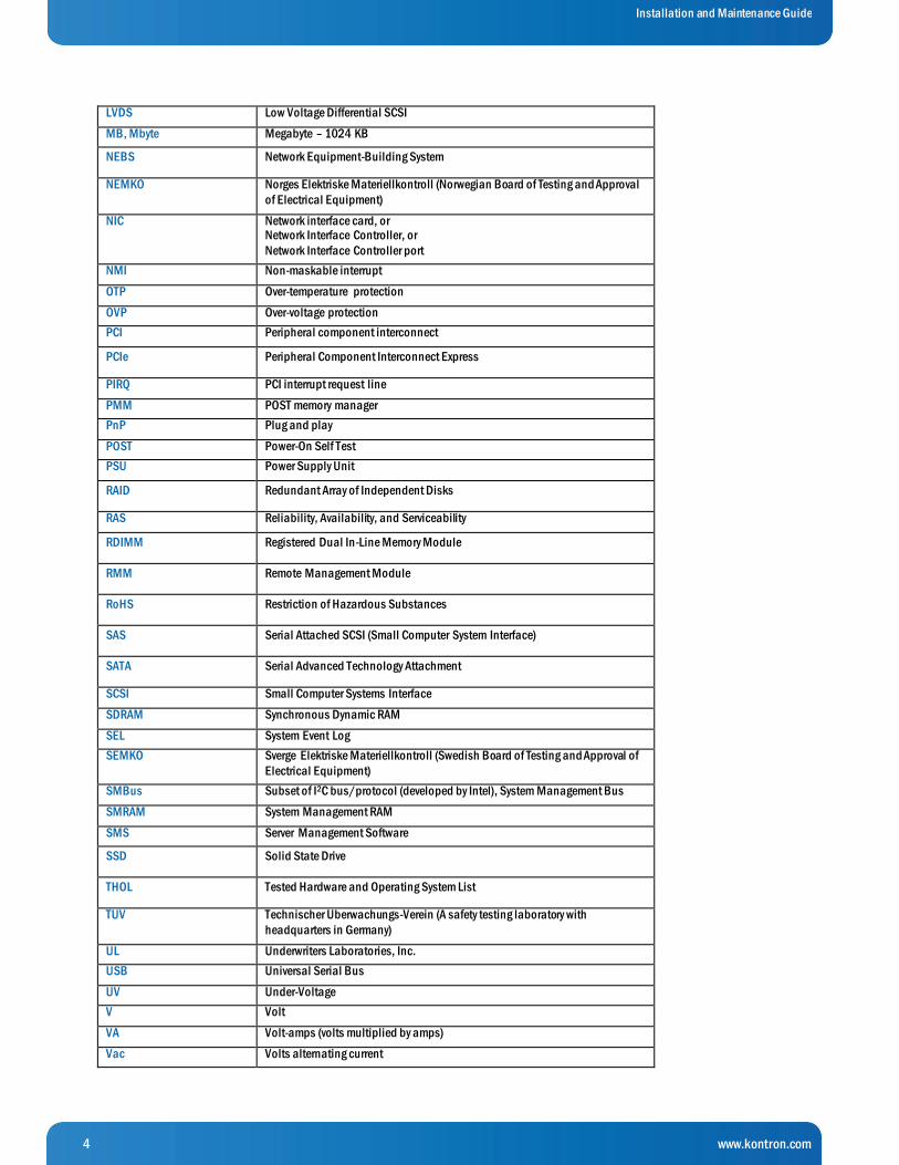
LVDS Low Voltage Differential SCSI
MB, Mbyte Megabyte – 1024 KB
NEBS Network Equipment-Building System
NEMKO Norges Elektriske Materiellkontroll (Norwegian Board of Testing and Approval
of Electrical Equipment)
NIC Network interface card, or Network Interface Controller, or
Network Interface Controller port
NMI Non-maskable interrupt
OTP Over-temperature protection
OVP Over-voltage protection
PCI Peripheral component interconnect
PCIe Peripheral Component Interconnect Express
PIRQ PCI interrupt request line
PMM POST memory manager
PnP Plug and play
POST Power-On Self Test
PSU Power Supply Unit
RAID Redundant Array of Independent Disks
RAS Reliability, Availability, and Serviceability
RDIMM Registered Dual In-Line Memory Module
RMM Remote Management Module
RoHS Restriction of Hazardous Substances
SAS Serial Attached SCSI (Small Computer System Interface)
SATA Serial Advanced Technology Attachment
SCSI Small Computer Systems Interface
SDRAM Synchronous Dynamic RAM
SEL System Event Log
SEMKO Sverge Elektriske Materiellkontroll (Swedish Board of Testing and Approval of
Electrical Equipment)
SMBus Subset of I2C bus/protocol (developed by Intel), System Management Bus
SMRAM System Management RAM
SMS Server Management Software
SSD Solid State Drive
THOL Tested Hardware and Operating System List
TUV Technischer Uberwachungs-Verein (A safety testing laboratory with
headquarters in Germany)
UL Underwriters Laboratories, Inc.
USB Universal Serial Bus
UV Under-Voltage
V Volt
VA Volt-amps (volts multiplied by amps)
Vac Volts alternating current

5 www.kontron.com
Installation and Maintenance Guide
Vdc Volts direct current
VDE Verband Deutscher Electrotechniker (German Institute of Electrical Engineers)
VGA Video Graphics Array
VSB Voltage standby
W Watt
Ω Ohm

6 www.kontron.com
Installation and Maintenance Guide
Table of Contents «
1 Information ............................................................................................................................... 13
1.1 Product Description .........................................................................................................................................................13
1.2 Purpose of this Document ...............................................................................................................................................13
2 System Overview ........................................................................................................................ 14
2.1 What the Server Includes ................................................................................................................................................14
2.2 Product Accessories .........................................................................................................................................................14
2.3 Additional Information and Software ............................................................................................................................15
3 Normal Maintenance Tasks ........................................................................................................ 16
3.1 Adding or Replacing Hot-Swappable Hard Disk Drives ................................................................................................16
3.1.1 Removing an HDD Carrier from the Chassis .........................................................................................................16
3.1.2 Installing a Hard Drive in a Carrier .......................................................................................................................17
3.2 Replacing System Fans ....................................................................................................................................................19
4 Disassembling Server Components ............................................................................................ 21
4.1 Before Beginning These Tasks ........................................................................................................................................21
4.1.1 Tools and Supplies Needed ....................................................................................................................................21
4.1.2 System References ..................................................................................................................................................21
4.2 (A) Removing the Chassis Top Cover ..............................................................................................................................21
4.3 (B) Removing a Riser Card Assembly .............................................................................................................................22
4.3.1 (B1) Removing the Left Riser Card Assembly ......................................................................................................22
4.3.2 (B2) Removing the Right Riser Card Assembly ...................................................................................................23
4.4 (C) Removing the Processor Air Duct .............................................................................................................................24
4.5 (D) Removing the Support Cross Bar .............................................................................................................................25
4.6 (E) Disconnecting Cables ................................................................................................................................................27
4.6.1 (E1) Disconnecting Baseboard Power Side Cables .............................................................................................30
4.6.2 Disconnecting Baseboard Signal Side Cables .....................................................................................................31
4.7 (F) Removing the SuperCap Battery Backup .................................................................................................................34
4.8 (G) Removing the Cable Bundle Bracket and Fan Cage ...............................................................................................34
4.9 (H) Removing the SAS Hot-Swap Backplane (HSBP) Board .......................................................................................35
4.10 (I) Removing the Front Bezel ....................................................................................................................................37
5 Installation and Maintenance Tasks .......................................................................................... 39
5.1 Before Beginning These Tasks ........................................................................................................................................39
5.1.1 Tools and Supplies Needed ....................................................................................................................................39
5.1.2 System References ..................................................................................................................................................39
5.2 Tasks with the Chassis Cover Removed ..........................................................................................................................39
5.2.1 Configuring Memory DIMMs ..................................................................................................................................39
7 www.kontron.com
Installation and Maintenance Guide
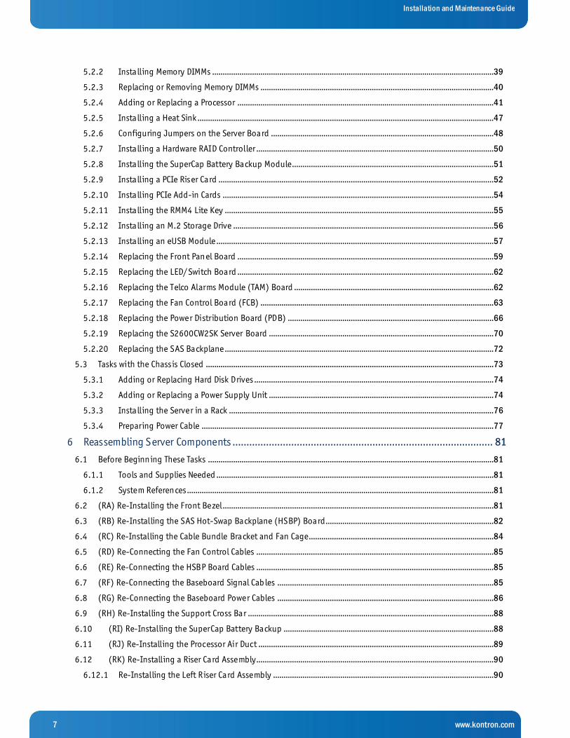
5.2.2 Installing Memory DIMMs ......................................................................................................................................39
5.2.3 Replacing or Removing Memory DIMMs ...............................................................................................................40
5.2.4 Adding or Replacing a Processor ..........................................................................................................................41
5.2.5 Installing a Heat Sink .............................................................................................................................................47
5.2.6 Configuring Jumpers on the Server Board ..........................................................................................................48
5.2.7 Installing a Hardware RAID Controller .................................................................................................................50
5.2.8 Installing the SuperCap Battery Backup Module ................................................................................................51
5.2.9 Installing a PCIe Riser Card ...................................................................................................................................52
5.2.10 Installing PCIe Add-in Cards .................................................................................................................................54
5.2.11 Installing the RMM4 Lite Key ................................................................................................................................55
5.2.12 Installing an M.2 Storage Drive ............................................................................................................................56
5.2.13 Installing an eUSB Module ....................................................................................................................................57
5.2.14 Replacing the Front Panel Board ..........................................................................................................................59
5.2.15 Replacing the LED/Switch Board ..........................................................................................................................62
5.2.16 Replacing the Telco Alarms Module (TAM) Board ...............................................................................................62
5.2.17 Replacing the Fan Control Board (FCB) ...............................................................................................................63
5.2.18 Replacing the Power Distribution Board (PDB) ..................................................................................................66
5.2.19 Replacing the S2600CW2SK Server Board ...........................................................................................................70
5.2.20 Replacing the SAS Backplane ................................................................................................................................72
5.3 Tasks with the Chassis Closed .........................................................................................................................................73
5.3.1 Adding or Replacing Hard Disk Drives ..................................................................................................................74
5.3.2 Adding or Replacing a Power Supply Unit ...........................................................................................................74
5.3.3 Installing the Server in a Rack ..............................................................................................................................76
5.3.4 Preparing Power Cable ...........................................................................................................................................77
6 Reassembling Server Components ............................................................................................. 81
6.1 Before Beginning These Tasks ........................................................................................................................................81
6.1.1 Tools and Supplies Needed ....................................................................................................................................81
6.1.2 System References ..................................................................................................................................................81
6.2 (RA) Re-Installing the Front Bezel .................................................................................................................................81
6.3 (RB) Re-Installing the SAS Hot-Swap Backplane (HSBP) Board................................................................................82
6.4 (RC) Re-Installing the Cable Bundle Bracket and Fan Cage........................................................................................84
6.5 (RD) Re-Connecting the Fan Control Cables .................................................................................................................85
6.6 (RE) Re-Connecting the HSBP Board Cables .................................................................................................................85
6.7 (RF) Re-Connecting the Baseboard Signal Cab les .......................................................................................................85
6.8 (RG) Re-Connecting the Baseboard Power Cables .......................................................................................................86
6.9 (RH) Re-Installing the Support Cross Bar .....................................................................................................................88
6.10 (RI) Re-Installing the SuperCap Battery Backup ....................................................................................................88
6.11 (RJ) Re-Installing the Processor Air Duct ................................................................................................................89
6.12 (RK) Re-Installing a Riser Card Assembly.................................................................................................................90
6.12.1 Re-Installing the Left Riser Card Assembly .........................................................................................................90

8 www.kontron.com
Installation and Maintenance Guide
6.12.2 Re-Installing the Right Riser Card Assembly .......................................................................................................91
6.13 (RL) Re-installing the Chassis Cover .........................................................................................................................92
7 Server Configuration and Utilities ............................................................................................. 94
7.1 Using the BIOS Setup Utility ...........................................................................................................................................94
7.1.1 Using BIOS Setup ....................................................................................................................................................94
7.1.2 Starting Setup .........................................................................................................................................................94
7.1.3 If You Cannot Access Setup ...................................................................................................................................94
7.1.4 Setup Menus ............................................................................................................................................................94
7.2 Single PSU or CPU System - Configuring Sensor Data Repository (SDR) ...................................................................95
7.2.1 Two (2) Power Supplies + Two (2) Processors Configuration ............................................................................95
7.2.2 Non-Redundant Power Unit and/or Single Processor Configuration ..............................................................95
7.3 Upgrading the System Firmware ....................................................................................................................................96
7.3.1 Upgrade Procedure for FW components...............................................................................................................96
7.4 BIOS Default and Password Reset Usage Procedure ....................................................................................................97
7.4.1 Set BIOS to Default (Clearing the CMOS) .............................................................................................................97
7.4.2 Clearing the Password ............................................................................................................................................98
7.5 Integrated BMC Force Update Procedure ......................................................................................................................98
7.6 ME Force Update Jumper .................................................................................................................................................99
7.7 BIOS Recovery Jumper .....................................................................................................................................................99
7.8 Restoring BIOS Default Settings ................................................................................................................................. 100
8 Troubleshooting ...................................................................................................................... 101
8.1 CPU Socket Inspection .................................................................................................................................................. 101
8.1.1 First Level Inspection .......................................................................................................................................... 101
8.1.2 Second Level Inspection ..................................................................................................................................... 101
8.2 Resetting the System .................................................................................................................................................... 102
8.3 Problems Following Initial System Installation ........................................................................................................ 102
8.3.1 First Steps Checklist ............................................................................................................................................ 103
8.4 Hardware Diagnostic Testing ....................................................................................................................................... 103
8.4.1 Verifying Proper Operation of Key System Lights ............................................................................................ 103
8.4.2 Confirming the Operating System Load ............................................................................................................ 104
8.5 Specif ic Problems and Corrective Actions .................................................................................................................. 104
8.5.1 Power Light does not Light................................................................................................................................. 104
8.5.2 No Characters Appear on Screen ........................................................................................................................ 104
8.5.3 Characters are Distorted or Incorrect ............................................................................................................... 105
8.5.4 System Cooling Fans do not Rotate Properly ................................................................................................... 105
8.5.5 Cannot Connect to a Server ................................................................................................................................ 105
8.5.6 Diagnostics Pass but the Connection Fails ....................................................................................................... 105
8.5.7 The (NIC) Controller Stopped Working When an Add-in Adapter was Installed .......................................... 106
8.5.8 The Add-in Adapter Stopped Working without Apparent Cause .................................................................... 106
8.5.9 System Boots When Installing a PCI Card ......................................................................................................... 106
9 www.kontron.com
Installation and Maintenance Guide
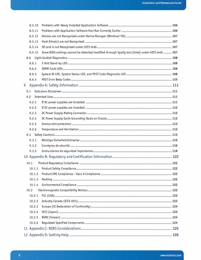
8.5.10 Problems with Newly Installed Application Software ..................................................................................... 106
8.5.11 Problems with Application Software that Ran Correctly Earlier .................................................................... 106
8.5.12 Devices are not Recognized under Device Manager (Windows*OS) .............................................................. 107
8.5.13 Hard Drive(s) are not Recognized ..................................................................................................................... 107
8.5.14 SD card is not Recognized under UEFI shell ..................................................................................................... 107
8.5.15 Some BIOS settings cannot be detected/modified through Syscfg tool (Intel) under UEFI shell ............ 107
8.6 Light-Guided Diagnostics ............................................................................................................................................. 108
8.6.1 5 Volt Stand-by LED ............................................................................................................................................. 108
8.6.2 DIMM Fault LEDs ................................................................................................................................................... 108
8.6.3 System ID LED, System Status LED, and POST Code Diagnostic LED .............................................................. 108
8.6.4 POST Error Beep Codes ........................................................................................................................................ 110
9 Appendix A: Safety Information .............................................................................................. 111
9.1 Emissions Disclaimer..................................................................................................................................................... 111
9.2 Intended Uses ................................................................................................................................................................ 111
9.2.1 If AC power supplies are installed: .................................................................................................................... 111
9.2.2 If DC power supplies are installed: .................................................................................................................... 112
9.2.3 DC Power Supply Mating Connector ................................................................................................................... 112
9.2.4 DC Power Supply Earth Grounding Studs on Chassis ....................................................................................... 113
9.2.5 Overcurrent protection ....................................................................................................................................... 113
9.2.6 Temperature and Ventilation ............................................................................................................................. 113
9.3 Safety Cautions .............................................................................................................................................................. 113
9.3.1 Wichtige Sicherheitshinweise ............................................................................................................................ 115
9.3.2 Consignes de sécurité ......................................................................................................................................... 116
9.3.3 Instru cciones de seguridad importantes .......................................................................................................... 118
10 Appendix B: Regulatory and Certification Information ............................................................ 122
10.1 Product Regulatory Compliance ............................................................................................................................. 122
10.1.1 Product Safety Compliance ................................................................................................................................. 122
10.1.2 Product EMC Compliance - Class A Compliance ................................................................................................ 122
10.1.3 Marking ................................................................................................................................................................. 122
10.1.4 Environmental Compliance ................................................................................................................................ 122
10.2 Electromagnetic Compatibility Notices ................................................................................................................. 123
10.2.1 FCC (USA) .............................................................................................................................................................. 123
10.2.2 Industry Canada (ICES-003)............................................................................................................................... 123
10.2.3 Europe (CE Declaration of Conformity) ............................................................................................................. 124
10.2.4 VCCI (Japan) ......................................................................................................................................................... 124
10.2.5 BSMI (Taiwan) ...................................................................................................................................................... 124
10.2.6 Regulated Specif ied Components ...................................................................................................................... 124
11 Appendix C: NEBS Considerations ............................................................................................ 125
12 Appendix D: Getting Help ........................................................................................................ 126

10 www.kontron.com
Installation and Maintenance Guide
12.1 World Wide Web ........................................................................................................................................................ 126
» Table of Figures «
Figure 1: Removing the Drive Carrier ...........................................................................................................................................17
Figure 2: Removing a Hard Drive...................................................................................................................................................17
Figure 3: Installing a Hard Drive ...................................................................................................................................................18
Figure 4: Inserting a New Hard Drive into the Chassis ...............................................................................................................18
Figure 5: Removing a Hot-Swappable Fan ...................................................................................................................................20
Figure 6: Removing the Cover .......................................................................................................................................................22
Figure 7: Left Riser Card Assembly ................................................................................................................................................23
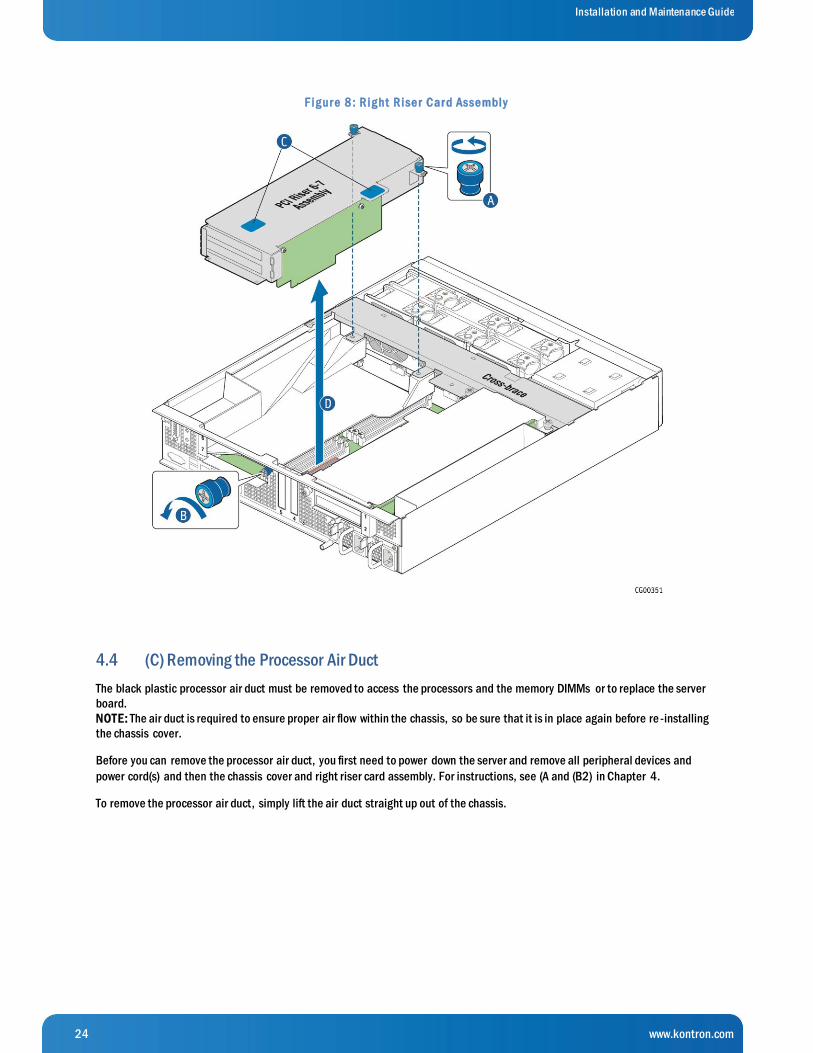
Figure 8: Right Riser Card Assembly .............................................................................................................................................24
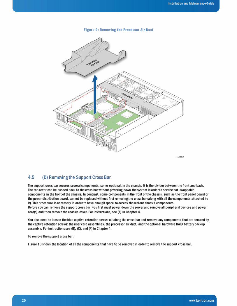
Figure 9: Removing the Processor Air Duct .................................................................................................................................25
Figure 10: Disconnecting Components fro m the Support Cross Bar ........................................................................................26
Figure 11: Removing the Support Cross Bar fro m the Chassis ..................................................................................................27
Figure 12: Cable Routing................................................................................................................................................................28
Figure 13: Disconnecting the CPU Power Cables .........................................................................................................................31
Figure 14: Removing the Battery Backup ....................................................................................................................................34
Figure 15: Removing the Cover Plate ...........................................................................................................................................36
Figure 16: Removing the Backplane Board .................................................................................................................................37
Figure 17: Removing the Front Bezel ...........................................................................................................................................38
Figure 18: Memory DIMM Installation ..........................................................................................................................................40
Figure 19: Using the Insertion-Removal Tool to Handle Processors ........................................................................................42
Figure 20: Cautions for Handling Processors ..............................................................................................................................43
Figure 21: Removing the Heat Sink ..............................................................................................................................................43
Figure 22: Using the Socket Levers...............................................................................................................................................44
Figure 23: Opening the Load Plate ...............................................................................................................................................44
Figure 24: Removing the Shipping Cover.....................................................................................................................................45
Figure 25: Manually Installing the Processor in the So cket ......................................................................................................46
Figure 26: Closing the Processor Load Plate ...............................................................................................................................46
Figure 27: Closing the Last Socket Lever .....................................................................................................................................47
Figure 28: Installing a Heat Sink ..................................................................................................................................................48
Figure 29: Jumper Blocks (J1E2, J1E6, J2J2, J1E4, J1E3) .......................................................................................................49

11 www.kontron.com
Installation and Maintenance Guide
Figure 30: Hardware RAID Adapter Layout ..................................................................................................................................50
Figure 31: Installing the RAID Contro ller Board .........................................................................................................................51
Figure 32: Setting Up the Battery Backup Assembly ..................................................................................................................52
Figure 33: Adding Riser Cards .......................................................................................................................................................53
Figure 34: Installing a PCIe Add-In Card in the Riser Card Assembly .......................................................................................54
Figure 35: Installing and Securing the Riser Card Assembly .....................................................................................................55
Figure 36: Installing the RMM4 Key ..............................................................................................................................................56
Figure 37: Installing an M.2 Flash Drive on the Server Board ...................................................................................................57
Figure 38: Installing an eUSB Flash Module on the Server Board ............................................................................................58
Figure 39: Front Panel Board Connectors ....................................................................................................................................59
Figure 40: Removing the Front Panel Board from the Chassis ..................................................................................................60
Figure 41: Installing the New FP Board ........................................................................................................................................61
Figure 42: Removing the TAM Board ............................................................................................................................................63
Figure 43: Fan Control Board Layout............................................................................................................................................65
Figure 44: Removing the PDB from the Chassis ..........................................................................................................................67
Figure 45: Removing the PDB Mounting Bracket ........................................................................................................................67
Figure 46: Attaching the PDB Mounting Bracket ........................................................................................................................68
Figure 47: Installing the New PDB in the Chassis .......................................................................................................................69
Figure 48: Removing the Server Board ........................................................................................................................................71
Figure 49: Removing the Air Duct from the Backplane Board ...................................................................................................73
Figure 50: Re-Attaching the Backplane Board to the Air Duct .................................................................................................73
Figure 51: Removing the PSU Filler Panel ....................................................................................................................................75
Figure 52: Installing a PSU in the Second Slot ...........................................................................................................................75
Figure 53: DC Power Supply Grounding........................................................................................................................................76
Figure 54: Re-Attaching the Front Bezel .....................................................................................................................................82
Figure 55: Re-Installing the Backplane Board ............................................................................................................................83
Figure 56: Re-Attaching the Cover Plate ......................................................................................................................................84
Figure 57: Routing the CPU Power Cables ....................................................................................................................................87
Figure 58: Re-Installing the Support Cross Bar ..........................................................................................................................88
Figure 59: Re-Installing the Battery Backup ...............................................................................................................................89
Figure 60: Re-Installing the Processor Air Du ct ..........................................................................................................................90
Figure 61: Re-Installing the Left Riser Card Assembly ...............................................................................................................91

12 www.kontron.com
Installation and Maintenance Guide
Figure 62: Re-Installing the Right Riser Card Assemb ly ............................................................................................................92
Figure 63: Re-Attaching the Chassis Cover ..................................................................................................................................93
Figure 64: Bent Pin Example ....................................................................................................................................................... 102
Figure 65: Contact Shifted Sideways Example ......................................................................................................................... 102
Figure 66: DC Power Supply Input Connector........................................................................................................................... 112
Figure 67: DC Power Supply Mating Connector ........................................................................................................................ 113
Electrostatic Discharge
CAUTION: The CG2300 server is sensitive to electrostatic discharge (ESD). Users must observe the appropriate precautions when
handling ESD-sensitive devices.
Limited Warranty Kontron grants the original purchaser of Kontron products a THREE YEAR LIMITED HARDWARE WARRANTY as described in the
following section below. However, no other warranties that may be granted or implied by anyone on behalf of Kontr on are valid
unless the consumer has the express written consent of Kontron.
Kontron warrants their own products, excluding software, to be free from manufacturing and mat erial defects for a period of
36 consecutive months from the date of purchase. This warranty is neither transferable nor extendible to cover any other users or
long-term storage of the product. It does not cover products that have been modified, altered, or repaired by any other party than
Kontron or their authorized agents. Furthermore, any product that has been, or is suspected of being, damaged as a result of
negligence, improper use, incorrect handling, servicing, or maintenance, or which has been damaged as a result of excessive
current/voltage or temperature, or which has had its serial number(s), any other markings or parts thereof altered, defaced or
removed will also be excluded from this warranty.
If the customer's eligibility for warranty has not been voided, in the event of any claim, he may return the product at the e arliest
possible convenience to the original place of purchase, together with a copy of the original document of purchase, a full
description of the application the product is used on, and a description of the defect. Pack the product in such a way as to ensure
safe transportation (see our safety instructions).
Kontron provides for repair or replacement of any part, assembly or sub-assembly at its own discretion, or to refund the original
cost of purchase, if appropriate. In the event of repair, refunding or replacement of any part, the ownership of the removed or
replaced parts reverts to Kontron, and the remaining part of the original guarantee, or any new guarantee to cover the repair ed or
replaced items, will be transferred to cover the new or repaired items. Any extensions to the original guarantee are considered
gestures of goodwill, and will be defined in the "Repair Report" issued by Kontron with the repaired or replaced item.
Kontron will not accept liability for any further claims resulting directly or indirectly from any warranty claim, other than the above
specified repair, replacement or refunding. In particular, all claims for damage to any system or process in which the product was
employed, or any loss incurred as a result of the product not functioning at any given time, are excluded. The extent of Kontron
liability to the customer shall not exceed the original purchase price of the item for which the claim exists.
Kontron issues no warranty or representation, either explicit or implicit, with respect to its products reliability, fitness, quality,
marketability or ability to fulfill any particular application or purpose. As a result, the products are sold "as is," and th e
responsibility to ensure their suitability for any given task remains that of the purchaser. In no event will Kontron be liable for
direct, indirect, or consequential damages resulting from the use of our hardware or software products or documentation, even if
Kontron were advised of the possibility of such claims prior to the purchase of the product or during any period since the date of
its purchase.
Please remember that no Kontron employee, dealer or agent is authorized to make any modification or addition to the above
specified terms, either verbally or in any other form, written or electronically transmitted, without the company's consent.

13 www.kontron.com
Installation and Maintenance Guide
1 Information
1.1 Product Description
The CG2300 Carrier Grade Server is the 7th generation of the Kontron 2U Carrier Grade Server products. The CG2300 server
supports Intel® Xeon® E5-2600 v3 and v4 series processors, coupling high performance with power efficiency to provide
improved performance-per-watt over previous generation rack-mount servers.
The CG2300 server is designed to meet NEBS-3 and ETSI certification, which makes it suited for a host of applications in the
telecom Central Office and industrial environment. The server is targeted to OSS (Operations System and Support), Billing,
Provisioning, Softswitch, Media Server, Wireless and Unified Messaging, Call Center , and many other applications. The CG2300
server can also support manufacturing, industrial, oil & gas, utility, and even military applications where a rugged, highly reliable
server is required for harsh environments such as dust, high altitude, fire hazard, earthquake propensity, and high ambient
temperatures.
To add to the many recognized benefits of the Kontron Carrier Grade Server family, the CG2300 server introduces several new
important features such as support of Intel® Xeon® v3 and v4 (E5-26XX v3, E5-26XX v4) processors, DDR4 memory, PCIe Gen3,
hot-swap/redundant fans and many flash storage formats (SD, eUSB, M.2).
More detailed product information about the CG2300 server is available on the Kontron website at:
http://www.kontron.com/products/systems/telecom-systems/cg2300-carrier-grade-rackmount-server.html
1.2 Purpose of this Document
This manual is for trained system technicians who are responsible for assembling/integrating systems, configuring hardware,
troubleshooting, upgrading and maintaining this server. This document provides a brief overview of the features of the system
followed by a list of accessories or other components available for purchase, instructions for how to add or replace components
in the CG2300 server, and troubleshooting information.
NOTE: Always be sure to search for CG2300 on the Support website at http://www.kontron.com/for the latest version of this
manual with possible updates since this version was published.
14 www.kontron.com
Installation and Maintenance Guide
2 System Overview
2.1 What the Server Includes
The CG2300 server includes the following components:
One 2U chassis »
One Intel® Server Board S2600CW2SK with DDR4 memory slots (memory not included) »
Six removable hard drive carriers »
DC or AC power subsystem: one or two hot-swappable power supply modules and a power distribution board. The »
number of power supplies depends on the selected configuration. When only one power supply is used, t he other power
supply bay has a filler panel in it.)
Six fan assemblies for cooling the processor(s), DIMM(s), PCI slot(s), and other internal components in three cooling »
zones.
A front panel board, an LED/switch board, and a telco alarms module (TAM) board »
Internal boards, cables and connectors »
2.2 Product Accessories
The following list shows the separately orderable components and optional accessories available for inclusion in the initial order
or to have as spares. Refer to the CG2300 Carrier Grade Server Configuration Guide for a complete list of orderable spares and
options. The Configuration Guide can be found on the Kontron Support Website at http://kontron.com/ (Rack Mount Systems -
CRMS - CG2300 - Ordering Guide).
LGA 2011-3 (socket R3) support for Intel® Xeon® E5-2600 v3 series processors »
Registered DDR4 Memory (RDIMM), and Load Reduced DDR4 Memory (LR-DIMM) »
Up to six hot-swappable 2.5” SAS HDDs or SATA SSDs »
Hard disk drive carriers (six already shipped with the server) »
Optional hardware RAID controller (low profile PCIe card) »
Two front access SD media flash modules »
Internal flash storage supported (eUSB and M.2) »
Two risers (four FH/FL cards) and two LP adapters for a total of six PCIe Gen3 I/O cards »
Power cord(s) »
AC or DC power supply module (850W) with redundancy option »
Intel® Remote Management Module 4 (RMM4Lite) option »
Rack mount kits »
For information about the accessories, memory, processors, and ordering information, refer to the CG2300 Carrier Grade Server Configuration Guide at http://kontron.com/ (CRMS - CG2300 - Ordering Guide).
For information about third-party hardware that has been tested and can be used with the system, refer to the CG2300 Carrier
Grade Server Tested Hardware and Operating System List (THOL) at http://kontron.com/ (Rack Mount Systems - CRMS –
CG2300 – Tested Hardware and Operating System List (THOL)).

15 www.kontron.com
Installation and Maintenance Guide
2.3 Additional Information and Software
If you need more technical information or information about the accessories that can be used with this CG2300 server, refer t o
the Technical Product Specification (TPS) for the system and/or for the server board. The TPS documents are located on the
Kontron support website at http://kontron.com/ (Rack Mount Systems - CRMS – CG2300). The system TPS provides in-depth
technical information about the server. The server board TPS provides in-depth technical information about the server board,
including BIOS settings and chipset information.
16 www.kontron.com
Installation and Maintenance Guide
3 Normal Maintenance Tasks
This chapter covers the tasks you will most likely and most often need to do on the CG2300 server. These tasks involve hot-
swappable components only, so there is no need to power down the server or remove the system cover.
3.1 Adding or Replacing Hot-Swappable Hard Disk Drives
Up to six hot-swappable SAS hard disk drives can be installed in the CG2300 server. The drives go into carriers that connect to
the SAS backplane board once the carriers with drives attached are inserted back into the drive bay slots. The CG2300 server
ships with six drive carriers.
While you must remove the front bezel to add or replace a hard drive in one of the drive slots, it is not necessary to remove the
chassis cover or to power down the system. The hard drives are hot-swappable.
CAUTION: If fewer than six hard disk drives are being installed, to maintain proper cooling the unused drive slots must contain the
empty carriers with filler panels that ship with the server.
The CG2300 server does not support all SAS HDD or SATA SSD disk drives. To see a list of validated manufacturers and drive
models, refer to the THOL. The latest version of the THOL is located on the Kontron support website at http://kontron.com.
(Rack Mount Systems - CRMS – CG2300 – Tested Hardware and Operating System List (THOL)).
NOTE: SATA rotating HDDs are not recommended for use in this system because they are sensitive to rotational vibration from
system fan blades.
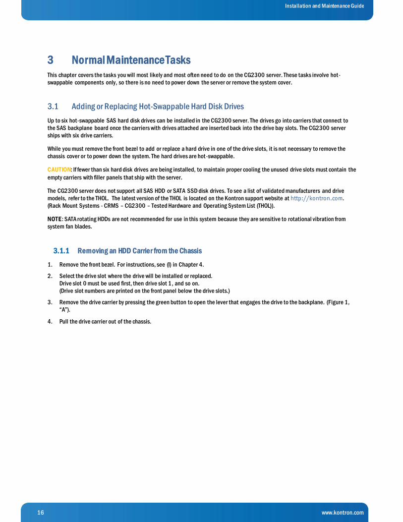
3.1.1 Removing an HDD Carrier from the Chassis
1. Remove the front bezel. For instructions, see (I) in Chapter 4.
2. Select the drive slot where the drive will be installed or replaced.
Drive slot 0 must be used first, then drive slot 1, and so on.
(Drive slot numbers are printed on the front panel below the drive slots.)
3. Remove the drive carrier by pressing the green button to open the lever that engages the drive to the backplane. (Figure 1,
“A”).
4. Pull the drive carrier out of the chassis.

17 www.kontron.com
Installation and Maintenance Guide
F ig ur e 1 : Re mov ing t he Dr iv e Car r ie r
3.1.2 Installing a Hard Drive in a Carrier
1. If the drive carrier is empty (that is, if you are installing a drive in it for the first time), remove the black plastic fil ler panel by
unfastening the four screws that attach it to the carrier. (Figure 2, “A”).
Set the screws aside for use with the new drive.
2. If a drive is already installed (that is, if you are replacing the drive), remove it by unfastening the four screws that a ttach the
drive to the drive carrier. (Figure 2, “A”)
Set the screws aside for use with the new drive.
3. Lift the drive (or filler panel) out of the carrier. (“B”)
F ig ur e 2 : Re mov ing a Har d Dr iv e

18 www.kontron.com
Installation and Maintenance Guide
4. Install the new drive in the drive carrier (Figure 3, “A”) and secure the drive with the four screws that come with the carrier
(with 4 lbs-in torque, max). (“B”)
F ig ur e 3 : Inst al l ing a Har d Dr iv e
5. With the drive carrier locking lever fully open, push the hard drive carrier into the drive slot in the chassis until it stops.
(Figure 4 “A”)
6. Press the locking lever until it snaps shut and secures the drive in the slot. (Figure 4 “B”)
If this is the last task you are doing, replace the front bezel. See (RA) in Chapter 6.
F ig ur e 4 : Inse r t ing a Ne w Har d Dr iv e int o t he Chassis

19 www.kontron.com
Installation and Maintenance Guide
3.2 Replacing System Fans
The fan replacement spare kit for the CG2300 server contains six 80mm fans. Each fan module is exactly like the fans in the
server, i.e., the bracket and plastic finger guard are attached. For ordering information, see the CG2300 Carrier Grade Server
Configuration Guide. The latest version of the Configuration Guide is located on the Kontron support website at
http://kontron.com. (Rack Mount Systems - CRMS – CG2300 - Ordering Guide). The fans are hot-swappable, so no service
interruption is usually required. However, if service interruption is required for installation considerations, fan replacement by a
skilled technician should take 15 minutes or less.
CAUTION: Because the fans are hot-swappable, you do not need to shut down the server system and disconnect the power and
external devices. Instead of removing the chassis cover, as is customary for working with internal components, simply press the
blue unlock button on the cover and slide the cover backwards on the shoulder screws to access the fan area.
Do not completely remove the top cover while the system is running because there is a 12V energy hazard in the server when
power is on. If the top cover has been removed to access components internal to the system other than the hot-swappable fans,
you must power off the server and unplug the power cords.
The six 80x38mm fans, configured as three redundant pairs are located behind the front panel board. (See XX, “Q”)These fans
are in front of the support cross bar and the fan control board. They provide cooling for the CPUs, memory DIMMs, PCI riser
assemblies, and HDD drives.
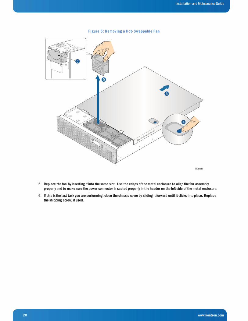
To replace a fan:
1. Unfasten the shipping screw, if used, on the left side of the chassis cover.
2. Slide the top cover back to the support cross bar so the fans and the CPU cables behind them are visible.
3. Determine which fan has failed by finding the LED that is amber. (The LED is next to the blue grommet on the top of
each fan assembly).
4. Remove the failing fan by grasping both sides of the fan assembly, using the plastic finger guard on the left side and
pulling the fan out of the metal enclosure that houses the fans and the power cables. (Figure 5 , “C” and “D”)
20 www.kontron.com
Installation and Maintenance Guide
F ig ur e 5 : Re mov ing a Hot - S wappable F an
5. Replace the fan by inserting it into the same slot. Use the edges of the metal enclosure to align the fan assembly
properly and to make sure the power connector is seated properly in the header on the left side of the metal enclosure.
6. If this is the last task you are performing, close the chassis cover by sliding it forward until it clicks into place. Replace
the shipping screw, if used.

21 www.kontron.com
Installation and Maintenance Guide
4 Disassembling Server Components
The following sections present general removal procedures that are required before removing or installing various internal
components that are not hot-swappable.
N O TE: Each section in this chapter has a letter (A through I) in the title. Tasks in this chapter and Chapter 5 identify the needed
disassembly tasks by these letters.
4.1 Before Beginning These Tasks
Before working with the server product, pay close attention to the safety instructions provided in this manual. See Appendix A,
“Appendix A: Safety Information”
WARNING: Electrostatic discharge (ESD) and ESD protection: ESD can damage disk drives, boards, and other parts. We
recommend that you perform all procedures in this chapter only at an ESD workstation. If one is not available, provide some E SD
protection by wearing an antistatic wrist strap attached to chassis ground (any unpainted metal surface) on the server when
handling parts.
N O TE: Except where noted, the tasks in this chapter require turning off the server and disconnecting the power cord(s) and any
peripheral devices attached to the server.
4.1.1 Tools and Supplies Needed
#1 and #2 Phillips (cross-point) screwdrivers (or interchangeable tip screwdriver with #1 and #2 Phillips bits) »
Personal grounding device such as an anti-static wrist strap and a grounded conductive pad »
4.1.2 System References
All references to left, right, front, rear, top, and bottom assume that you are facing the front of the server, as it would be
positioned for normal operation.
4.2 (A) Removing the Chassis Top Cover
The CG2300 server must be operated with the top cover in place to ensure proper cooling. Always power down the system and
remove the top cover to add or replace any components inside the chassis that are not hot-swappable.
CAUTION: 5V standby power is present inside the chassis whenever the power supply module(s) are connected to a power source.
Before removing the top cover, always power down the server and unplug all peripheral devices and the power cable(s).
A non-skid surface or a stop behind the server may be needed to prevent the server from sliding on the work surface.
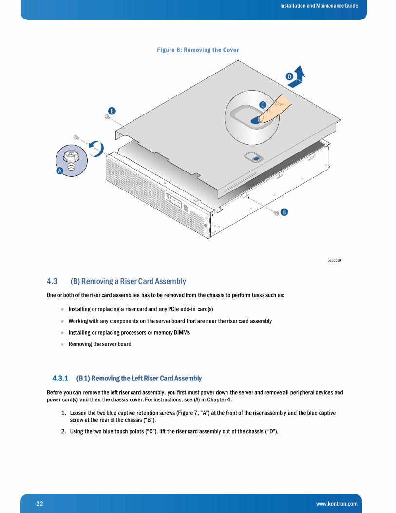
Figure 6 shows the top cover and how it is removed. Follow these steps to remove the cover:
1. Remove the hex HD Phillips 6-32 shipping screw at the front left side of the cover, if it is still attached, and save it for
future use. (Figure 6, “A”)
2. Remove the two shoulder screws (one on each side) from the cover. (“B”)
3. While holding the blue unlocking button at the middle of the top cover ( “C”), slide the cover backwards until it stops
and the edge clears the lock bracket on the rear panel of the chassis
4. Lift the cover straight up to remove it from the chassis. (“D”)
22 www.kontron.com
Installation and Maintenance Guide
F ig ur e 6 : Re mov ing t he Cov e r
4.3 (B) Removing a Riser Card Assembly
One or both of the riser card assemblies has to be removed from the chassis to perform tasks such as:
Installing or replacing a riser card and any PCIe add-in card(s) »
Working with any components on the server board that are near the riser card assembly »
Installing or replacing processors or memory DIMMs »
Removing the server board »
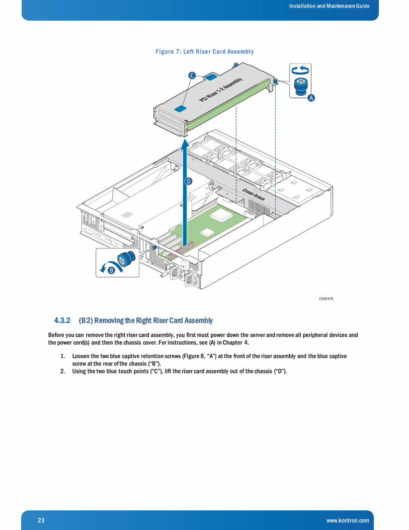
4.3.1 (B1) Removing the Left Riser Card Assembly
Before you can remove the left riser card assembly, you first must power down the server and remove all peripheral devices and
power cord(s) and then the chassis cover. For instructions, see (A) in Chapter 4.
1. Loosen the two blue captive retention screws (Figure 7, “A”) at the front of the riser assembly and the blue captive
screw at the rear of the chassis (“B”).
2. Using the two blue touch points (“C”), lift the riser card assembly out of the chassis (“D”).
23 www.kontron.com
Installation and Maintenance Guide
F ig ur e 7 : Le ft Rise r Car d Asse mbl y
4.3.2 (B2) Removing the Right Riser Card Assembly
Before you can remove the right riser card assembly, you first must power down the server and remove all peripheral devices and
the power cord(s) and then the chassis cover. For instructions, see (A) in Chapter 4.
1. Loosen the two blue captive retention screws (Figure 8, “A”) at the front of the riser assembly and the blue captive
screw at the rear of the chassis (“B”).
2. Using the two blue touch points (“C”), lift the riser card assembly out of the chassis (“D”).
24 www.kontron.com
Installation and Maintenance Guide
F ig ur e 8 : Rig ht Rise r Car d Asse mbly
4.4 (C) Removing the Processor Air Duct
The black plastic processor air duct must be removed to access the processors and the memory DIMMs or to replace the server
board.
NOTE: The air duct is required to ensure proper air flow within the chassis, so be sure that it is in place again before re -installing
the chassis cover.
Before you can remove the processor air duct, you first need to power down the server and remove all peripheral devices and
power cord(s) and then the chassis cover and right riser card assembly. For instructions, see (A and (B2) in Chapter 4.
To remove the processor air duct, simply lift the air duct straight up out of the chassis.
25 www.kontron.com
Installation and Maintenance Guide
F ig ur e 9 : Re mov ing t he Pr oce ssor Air Duct
4.5 (D) Removing the Support Cross Bar
The support cross bar secures several components, some optional, in the chassis. It is the divider between the front and back.
The top cover can be pushed back to the cross bar without powering down the system in order to service hot -swappable
components in the front of the chassis. In contrast, some components in the front of the chassis, such as the front panel board or
the power distribution board, cannot be replaced without first removing the cross bar (along with all the components attached to
it). This procedure is necessary in order to have enough space to access these front chassis components.
Before you can remove the support cross bar, you first must power down the server and remove all peripheral devices and power
cord(s) and then remove the chassis cover. For instructions, see (A) in Chapter 4.
You also need to loosen the blue captive retention screws all along the cross bar and remove any components that are secured by
the captive retention screws: the riser card assemblies, the processor air duct, and the optional hardware RAID battery backup
assembly. For instructions see (B), (C), and (F) in Chapter 4.
To remove the support cross bar:
Figure 10 shows the location of all the components that have to be removed in order to remove the support cross bar.

26 www.kontron.com
Installation and Maintenance Guide
F ig ur e 1 0 : Disconne ct ing Compone nt s fr om t he S uppor t Cr oss Bar
1. Remove the small flat screws that fasten the cross bar to the sides of the chassis. There is one screw on the left side
and two on the right side. (Figure 11)
2. Remove the support cross bar from the chassis and set it aside. (Figure 11)

27 www.kontron.com
Installation and Maintenance Guide
F ig ur e 1 1 : Re mov ing t he S uppor t Cr oss Bar fr om t he Chassis
4.6 (E) Disconnecting Cables
Cables must be disconnected in order to do several different tasks inside the CG2300 server. Figure 12 and Table 1 show all of
the cable connections in the system.
Before you can disconnect any internal cables, you first must power down the server and remove all peripheral devices and power
cord(s) and then remove the chassis cover. For instructions, see (A) in Chapter 4.

28 www.kontron.com
Installation and Maintenance Guide
F ig ur e 1 2 : Cable Rout ing
Table 1 provides information about each of the numbered connections in Figure 12.
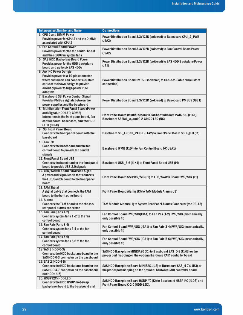
Table 1 : Cable Conne ct ions
I n terconnect Number and Name Co nnections
1. Baseboard SSI Main Power
Provides power to the baseboard and the power supply with the PS-ON signal
Power Distribution Board 3.3V D2D (soldered) to Baseboard MAIN_PWR (J9G1)
2. CPU 1 and DIMM Power
Provides power for CPU 1 and the DIMMs
associated with CPU 1
Power Distribution Board 3.3V D2D (soldered) to Baseboard CPU_1_PWR
(J8K2)
29 www.kontron.com
Installation and Maintenance Guide
I n terconnect Number and Name Co nnections
3. CPU 2 and DIMM Power
Provides power for CPU 2 and the DIMMs associated with CPU 2
Power Distribution Board 3.3V D2D (soldered) to Baseboard CPU_2_PWR (J9A2)
4. Fan Control Board Power
Provides power for the fan control board
and the six 80mm system fans
Power Distribution Board 3.3V D2D (soldered) to Fan Control Board Power
(J9A2)
5. SAS HDD Backplane Board Power
Provides power for the HDD backplane board and up to six SAS HDDs
Power Distribution Board 3.3V D2D (soldered) to SAS HDD Backplane Power (J11)
6. Aux I/O Power Dongle
Provides power to a 10-pin connector
where customers can connect a custom cable of their own design to provide
auxiliary power to high-power PCIe adapters
Power Distribution Board 5V D2D (soldered) to Cable-to-Cable NC (custom connection)
7. Baseboard SSI Power Control Signal Provides PMBus signals between the
power supplies and the baseboard
Power Distribution Board 3.3V D2D (soldered) to Baseboard PMBUS (J9E1)
8. Multifunction Front Panel Board (Power
and Signal, HDD LED, COM2) Interconnects the front panel board, fan
control board, baseboard, and the HDD
LEDs (C-2-C)
Front Panel Board (multifunction) to Fan Control Board PWR/SIG (J1A1), Baseboard SERIAL_A, and C-2-C HDD LED (NC)
9. SSI Front Panel Board Connects the front panel board with the
baseboard
Baseboard SSI_FRONT_PANEL (J1A2) to Front Panel Board SSI signal (J1)
10. Fan I2C Connects the baseboard and the fan
control board to provide fan control
signals
Baseboard IPMB (J1D4) to Fan Control Board I2C (J8A1)
11. Front Panel Board USB
Connects the baseboard to the front panel board to provide USB 2.0 signals
Baseboard USB_5-6 (J1K1) to Front Panel Board USB (J4)
12. LED/Switch Board Power and Signal
A power and signal cable that connects
the LED/switch board to the front panel board
Front Panel Board SSI PWR/SIG (J2) to LED/Switch Board PWR/SIG (J1)
13. TAM Signal A signal cable that connects the TAM
board to the front panel board
Front Panel Board Alarms (J3) to TAM Module Alarms (J2)
14. Alarms
Connects the TAM board to the chassis rear panel alarms connector
TAM Module Alarms(J1) to System Rear Panel Alarms Connector (the DB-15)
15. Fan Pair (Fans 1-2)
Connects system fans 1 -2 to the fan
control board
Fan Control Board PWR/SIG(J3A1) to Fan Pair (1-2) PWR/SIG (mechanically,
only possible fit)
16. Fan Pair (Fans 3-4)
Connects system fans 3-4 to the fan control board
Fan Control Board PWR/SIG (J6A1) to Fan Pair (3-4) PWR/SIG (mechanically, only possible fit)
17. Fan Pair (Fans 5-6)
Connects system fans 5-6 to the fan
control board
Fan Control Board PWR/SIG (J9A1) to Fan Pair (5-6) PWR/SIG (mechanically,
only possible fit)
18 SAS 1 (HDD 0-3)
Connects the HDD backplane board to the SAS HDD 0-3 connector on the baseboard
SAS HDD Backplane MINISAS0 (J1) to Baseboard SAS_0-3 (J1H3) or the proper port mapping on the optional hardware RAID controller board
19. SAS 2 (HDD 4-5)
Connects the HDD backplane board to the
SAS HDD 4-7 connector on the baseboard (for HDDs 4-5)
SAS HDD Backplane Board MINISAS1 (J3) to Baseboard SAS_4-7 (J1H3) or
the proper port mapping on the optional hardware RAID controller board
20. HSBP I2C/HDD LED Connects the HDD HSBP (hot-swap
backplane) board to the baseboard and
SAS HDD Backplane Board HSBP I2C (J2) to Baseboard HSBP I2C (J1D3) and Front Panel Board C-2-C (HDD-LED).

30 www.kontron.com
Installation and Maintenance Guide
I n terconnect Number and Name Co nnections
front panel board to provide HDD LED
signal control on the disk drive carriers and on the system front panel
4.6.1 (E1) Disconnecting Baseboard Power Side Cables
The four baseboard power side cables all run from the power distribution board, across the cable bundle bracket in protective
covers, to their connectors on the baseboard.
The baseboard power cables need to be disconnected on the baseboard side (soldered on the PDB side) before performing tasks
such as replacing the power distribution board or replacing the server board. Because these baseboard power cables are carrie d
on the cable bundle bracket, they also need to be disconnected for any task that requires the fan cage/cable bracket assembly
to be removed from the chassis.
Before you can disconnect the baseboard power cables from their baseboard connectors, you must first remove the right riser
card assembly, the processor air duct and the support cross bar. For instructions, see (B2), (C), and (D) in Chapter 4.
Disconnecting Main Power
The baseboard SSI main power cable provides power to the baseboard and the power supply with the “PS -ON” signal from the
power distribution board. The cable is soldered to the PDB and connected to MAIN_PWR (J9G1).
For the location of the connector on the baseboard, see Figure 12 in this section (E).
To disconnect the main power cable
1. If present, uncover the black insulator covering the power cable bundles in the cable bracket. See Figure 13.
2. Disconnect the main power cable bundle from the baseboard and pull it to the side of the system.
(Since the cable is soldered onto the power distribution board, it cannot be removed from the chassis, but you can pull it over
to the left side, out of the way, when working with components in the front of the chassis.)
Disconnecting the PMBus (SSI Power Control) Cable
This cable sends PMBus signals between the power supplies and the baseboard. It is soldered on the PDB side and connects to
the baseboard PMBus connector (J9E1) on the other end.
For the location of the PMBus connector on the baseboard, see Figure 12 in this section (E).
To disconnect the PMBus cable:
1. If present, uncover the black insulator covering the power cable bundles in the cable bracket under the cross bar. See Figure
13.
2. Disconnect the PMBus power cable from the baseboard and pull it to the side of the system.
(Since the cable is soldered onto the power distribution board, it cannot be removed from the chassis, but you can pull it
over to the left side, out of the way, when working with components in the front of the chassis.)
Disconnecting the CPU 1 and CPU 2 Power Connectors
The CPU1 and CPU2 power cables bring power from the power distribution board to the CPUs (and their DIMMs). The CPU1 cable
connects to the baseboard at the front of the board near the CPU1 DIMMs, (CPU_1_PWR, J8K2). The CPU2 cable is routed through
another black insulator along the right chassis wall to a connector at the rear right side of the board, (CPU_1_PWR, J9A2).
For the locations of these cables, see Figure 12 in this section (E).

31 www.kontron.com
Installation and Maintenance Guide
NOTE: Besides the components already mentioned, you may find you also need to remove the cable bundle bracket/fan cage
assembly in order to access the CPU1 cable connector on the baseboard. For instructions, see (G) in Chapter 4.
To disconnect the CPU1 and CPU2 power cables:
1. If present, uncover the black insulator covering the CPU 1 and CPU 2 power cable bundles in the cable bracket. (Figure 13)
2. Disconnect the CPU power cables from the baseboard and pull them to the side of the system.
(Since the cables are soldered onto the power distribution board, they cannot be removed from the chassis, but you can pull
them over to the left side, out of the way, when working with components in the front of the chassis.)
F ig ur e 1 3 : Disconne ct ing t he CPU Powe r Cable s
4.6.2 Disconnecting Baseboard Signal Side Cables
Signal cables connect to the baseboard on the left side. See Figure 12 in this section (E).
Before you can disconnect any baseboard signal cables, you must first power down the server and remove all peripheral devices
and power cord(s) and then remove the chassis cover and the left riser card assembly. For instructions, see (A) and (B1) in
Chapter 4.
(E2)Baseboard to Front Panel Board Signal Cables
These cables all have a baseboard connection and a front panel board connection.
Before you can disconnect any of these baseboard-to-FBP cables from the front panel board (FPB), you must first remove all the
things that are in the way for working on the FPB: the support cross bar and the components attached to it, the cable bundles in
the cable bracket, and the cable bracket/fan cage. For instructions, see (D), (E1), and (G) in Chapter 4.
S S I Front Panel Board Cable

32 www.kontron.com
Installation and Maintenance Guide
The SSI signal cable must be disconnected in order to perform tasks such as replacing the front panel board or replacing the
server board.
The SSI front panel board signal cable connects the front panel board connector (J1) with the baseboard (SSI_FRONT_PANEL,
J1A2).
For the location of the baseboard SSI front panel board connector, see Figure 12 in this cable section (E).
For the location of the SSI power control signal connector on the FPB, see Figure 39 in Section 5.2.14.
S e rial Cable
In order to remove the server board, you need to disconnect the serial cable, which is part of the multifunction front panel board
power and signal cable, from the baseboard. Since this cable is part of the multifunction front panel board cable, you also need
to disconnect it to replace the fan control board, or to work with the HDD LEDs.
As part of the multifunction front panel board cable, along with the HDD LED cable and COM2, the serial cable interconnects t he
front panel board (FPB) with the fan control board, the baseboard, and the HDD LEDs. For the location of the multifunction cable
connector on the FPB (J1A1), see Figure 39 in Section 5.2.14. For the location of the serial connector on the baseboard
(SERIAL_A), see Figure 12 in this section (E).
F r ont Panel Board USB Cable
The USB cable has to be disconnected in order to perform tasks such as replacing the front panel board or replacing the server
board.
The front panel board USB cable connects the baseboard to the FPB to provide USB 2.0 signals.
For the location of the baseboard USB connector (USB-5-6, J1K1), see Figure 12 in this section (E). For the location of the USB
connector on the FPB (J4), see Figure 39 in Section 5.2.14.
(E3) Other Baseboard Signal Cables
IPMB/Fan I2C Cable
The IPMB cable (aka Fan I2C) has to be disconnected in order to perform tasks such as replacing the server board or replacing the
fan control board.
The IPMB cable connects the baseboard with the fan control board (FCB) to provide fan control signals. For the location of the
IPMB connector (J1D4) on the baseboard, see Figure 12 in Chapter 4. For the FCB I2C connector (J8A1), see Figure 43 in Section
5.2.17.
Before you can disconnect the IPMB/Fan I2C connector on the FCB, you need to remove everything that is in the way for working
on the FCB: the support cross bar, the baseboard power cables, the cable bundle bracket/fan cage. For instructions, see (D),
(E1), and (G) in Chapter 4.
HS BP I2C Cable
The HSBP I2C cable has to be disconnected in order to perform tasks such as replacing the SAS backplane, the front panel board,
or the server board.
The HSBP I2C cable connects the HDD HSBP (hot-swap backplane) to the baseboard and the front panel board to provide HDD
LED signal control on the disk drive carriers and on the system front panel. For the location of the HSBP I2C connector (J2) on the
HDD backplane, see Figure 16 in Section 5.2.20. For the location of the HSBP I2C/HDD LED connector (HDD-LED) on the FP
board, see Figure 39 in Section5.2.14. For the location of the HSBP I2C connector (J1D3) on the baseboard, see Figure 12 in
Chapter 4.
Before you can disconnect the HSBP I2C/HDD LED cable from the SAS backplane, you must first remove the front bezel, the
active HDD carriers from the drive bay, and the HSBP backplane and air duct from the SAS HDD drive bay assembly. For
instructions, see (I) and (H) in Chapter 4.
33 www.kontron.com
Installation and Maintenance Guide
Before you can disconnect the HSBP I2C cable from the FP board, you need to remove everything that is in the way for working on
the front panel board: the support cross bar, the power cable bundles in the cable bracket, and the cable bundle bracket/fan
cage assembly. For instructions, see (D), (E1), and (G) in Chapter 4.
(E4) HSBP Cables
The HSBP cables have to be disconnected from the baseboard in order to perform tasks such as installing a hardware RAID
controller or replacing the server board or power distribution board.
The HSBP cables have to be disconnected from the HSBP board on the SAS drive bay assembly to replace the PDB or to remove
or replace the HSBP board.
The hot-swap backplane at the back of the SAS HDD drive bay assembly has the following cables connected:
SAS HDD Backplane board power cable that provides power from the PDB to the HSBP and up to six SAS HDDs »
For the location of the power connector (J11) on the HSBP, see Figure 16 in (H) in Chapter 4. The other end of this cable
is soldered onto the PDB.
SAS-1 (HDD 0-3) cable that connects the HSBP board to the SAS_0-3 connector on the baseboard or to an optional »
hardware RAID controller board
For the location of the SAS-1 connector (MINISAS0, J1) on the HSBP, see Figure 16 in (H) in Chapter 4. For the location
of the SAS_0-3 connector (J1H3) on the baseboard, see Figure 12 in this section (E).
For the location of the SAS-1 connector on a hardware RAID controller card, see Figure 30 in Section 5.2.7 “Installing a
Hardware RAID Controller”.
SAS-2 (HDD 4-5) cable that connects the HSBP board to the SAS_4-7 connector on the baseboard or to an optional »
hardware RAID controller board
For the location of the SAS-2 connector (MINISAS1, J3) on the HSBP, see Figure 16 in (H) in Chapter 4. For the location
of the SAS_4-7 connector (J1H3) on the baseboard, see Figure 12 in this section (E).
For the location of the SAS-1 connector on a hardware RAID controller card, see Figure 30 in Section 5.2.7 “Installing a
Hardware RAID Controller”.
Before you can disconnect the SAS-1 and SAS-2 cables from the baseboard, you need to remove the left riser card assembly. For
instructions, see (B1) in Chapter 4.
Before you can disconnect the HSBP SAS-1 and SAS-2 cables and the HSBP power cable from the HSBP board, you must first
remove the front bezel, the active HDD carriers from the drive bay, and the HSBP backplane and air duct from the SAS HDD driv e
bay assembly. For instructions, see (I) and (H) in this chapter.
(E5) Fan Control Board Cables
The fan control board cables have to be disconnected in order to perform tasks such as replacing the front panel board (FPB),
removing or replacing the fan control board (FCB), or replacing the power distribution board (PDB).
The fan control board has the following cables:
Fan Control Board PWR/SIG cable, which is part of the FPB multifunction connection that coordinates signals to the »
front panel
For the location of the FCB PWR/SIG connector (J1A1) on the FCB, see Figure 43 in Section 5.2.17.
Fan I2C cable, which connects the baseboard and the fan control board to provide fan control signals »
NOTE: This cable, also known as the IPMB cable, is covered in (E3) in this section (E).
Fan (Fans 1-2), Fan (Fans 3-4), Fan (Fans 5-6) cables, which each connect the FCB with a fan pair in the fan cage. »
For the location of the three fan pair connectors (J3A1, J6A1, J9A1) on the FCB, see Figure 43 in Section 5.2.17.
These cables are connected mechanically on the fan pairs in the fan cage.
Fan Control Board Power cable, which provides power from the PDB (soldered) to the FCB and the six fans »
For the location of the FCB power connector (J9A2) on the FCB, see Figure 43 in Section 5.2.17.
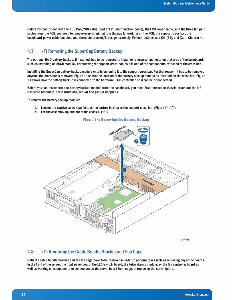
34 www.kontron.com
Installation and Maintenance Guide
Before you can disconnect the FCB PWR/SIG cable (part of FPB multifunction cable), the FCB power cable, and the three fan pair
cables from the FCB, you need to remove everything that is in the way for working on the FCB: the support cross bar, the
baseboard power cable bundles, and the cable bracket/fan cage assembly. For instructions, see (D), (E1), and (G) in Chapter 4.
4.7 (F) Removing the SuperCap Battery Backup
The optional RAID battery backup, if installed, has to be removed to install or remove components on that area of the baseboard,
such as installing an eUSB module, or removing the support cross bar, as it is one of the components attached to the cross bar.
Installing the SuperCap battery backup module entails fastening it to the support cross bar. For that reason, it has to be removed
anytime the cross bar is removed. Figure 14 shows the location of the battery backup module as installed on the cross bar. Figure
31 shows how the battery backup is connected to the hardware RAID controller, so it can be disconnected.
Before you can disconnect the battery backup module from the baseboard, you must first remove the chassis cover and the left
riser card assembly. For instructions, see (A) and (B1) in Chapter 4.
To remove the battery backup module:
1. Loosen the captive screw that fastens the battery backup to the support cross bar. (Figure 14, “A”)
2. Lift the assembly up and out of the chassis. (“B”)
F ig ur e 1 4 : Re mov ing t he Bat t e r y Back up
4.8 (G) Removing the Cable Bundle Bracket and Fan Cage
Both the cable bundle bracket and the fan cage have to be removed in order to perform tasks such as replacing any of the boards
in the front of the server: the front panel board, the LED/switch board, the telco alarms module, or the fan controller board as
well as working on components or connectors on the server board front edge, or replacing the server board.

35 www.kontron.com
Installation and Maintenance Guide
The cable bundle bracket is under the support cross bar and just behind the fan cage. It is attached to the fan cage by two small
screws. Because both of these components need to be removed and are fastened together, they are treated as one assembly.
Before you can remove the cable bundle bracket/fan cage, you must first remove (and unplug were applicable)
the chassis cover »
All six fans from the cage. Set the fans aside. »
The support cross bar and all the components attached to it »
The four power cable bundles. Move them away from the FCB. »
All three fan cables from the fan control board. »
For instructions, see (A), (D), (E1), and (E5) in Chapter 4.
To remove the fan cage:
1. Unfasten the two screws that fasten the fan cage to the chassis floor. Pull the cage up out of the chassis and set it and the
screws aside.
4.9 (H) Removing the SAS Hot-Swap Backplane (HSBP) Board
The HSBP board has to be removed in order to perform tasks such as replacing the HSBP board or replacing the PDB.
CAUTION: Before removing or replacing any of the boards on the CG2300 server, you must first take the server out of service, turn
off all peripheral devices connected to the server, turn off the server by pressing the power button, and unplug the power co rd(s)
from the system and wall outlet.
When handling the SAS backplane board, observe the normal safety and ESD precautions. See “Appendix A: Safety Information”
for more information.
The six-slot SAS backplane board is located at the rear of the HDD drive bay assembly. It is held in place by a cover plate on top
of the HDD bay assembly that goes over the top edge of the backplane board. There is also a black plastic air duct surrounding
the drive bay on the right side and rear of the assembly.
Before you can remove the HSBP board, you must first remove the chassis cover and front bezel. For instructions, see (A) and (I) in
Chapter 4.
Once you have removed the HSBP board from the drive bay assembly, you need to remove the four cables connected to the
board:
SAS HDD backplane board power cable. »
SAS 1 and SAS 2 cables »
HSBP I2C/HDD LED cable »
For instructions, see (E3) and (E4) in Chapter 4.
To remove the HSBP board:
1. Slide any hard disk drives out from the drive bay slots to disengage them from the backplane.
2. Remove the cover plate on the HDD bay assembly by loosening the screw that fastens it to the drive bay and sliding it to
the left towards the chassis wall to release the tabs. (Figure 15, “A” and “B”)
3. Lift the cover plate off of the HDD bay assembly. (“C”)
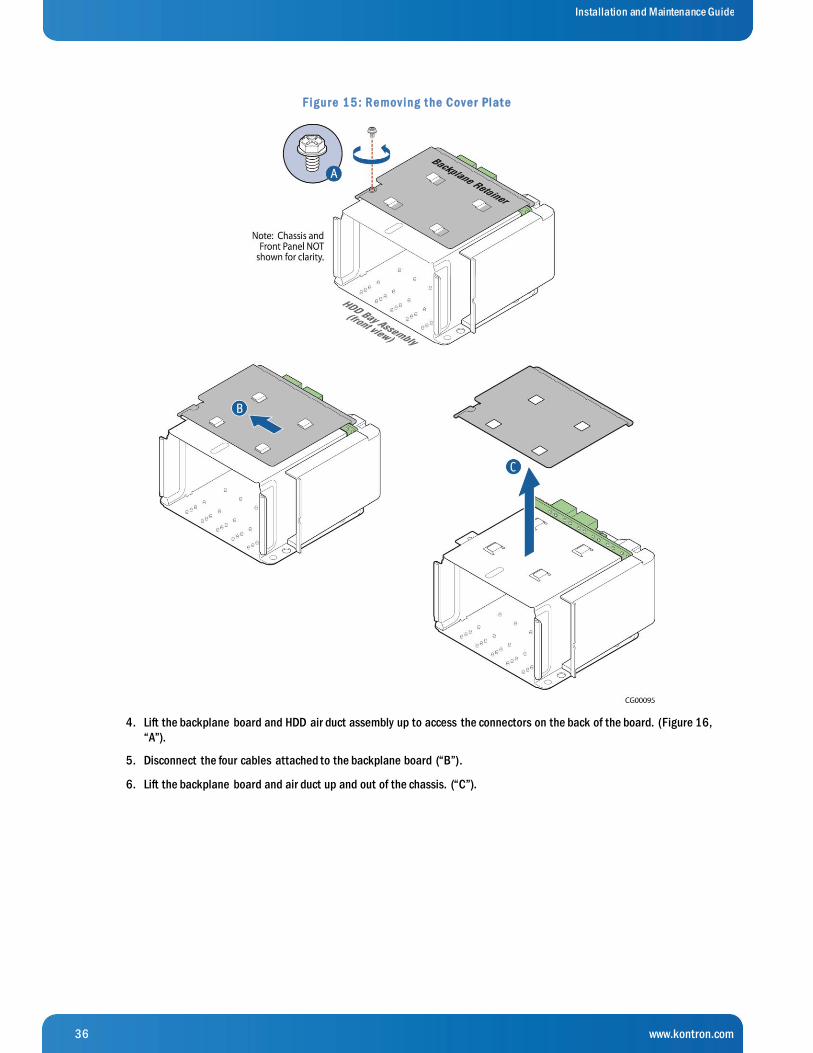
36 www.kontron.com
Installation and Maintenance Guide
F ig ur e 1 5 : Re mov ing t he Cov e r Plat e
4. Lift the backplane board and HDD air duct assembly up to access the connectors on the back of the board. (Figure 16,
“A”).
5. Disconnect the four cables attached to the backplane board (“B”).
6. Lift the backplane board and air duct up and out of the chassis. (“C”).
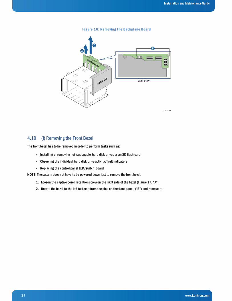
37 www.kontron.com
Installation and Maintenance Guide
F ig ur e 1 6 : Re mov ing t he Back plane Boar d
4.10 (I) Removing the Front Bezel
The front bezel has to be removed in order to perform tasks such as:
Installing or removing hot-swappable hard disk drives or an SD flash card »
Observing the individual hard disk drive activity/fault indicators »
Replacing the control panel LED/switch board »
NOTE: The system does not have to be powered down just to remove the front bezel.
1. Loosen the captive bezel retention screw on the right side of the bezel (Figure 17, “A”).
2. Rotate the bezel to the left to free it from the pins on the front panel, (“B”) and remove it.

38 www.kontron.com
Installation and Maintenance Guide
F ig ur e 1 7 : Re mov ing t he F r ont Be ze l
39 www.kontron.com
Installation and Maintenance Guide
5 Installation and Maintenance Tasks
This chapter covers separately-orderable components that you may want to add or replace in your Kontron CG2300 Carrier Grade
Server. Most of these components can be ordered as accessories from Kontron and some are from third party vendors. For more
information about what is available from Kontron, see the CG2300 Carrier Grade Server Configuration Guide. For a list of
qualified third party vendors, see the Tested Hardware and Operating System List (THOL). The latest version of the Configuration
Guide is located on the Kontron support website at http://kontron.com (Rack Mount Systems - CRMS – CG2300 - Ordering
Guide). The latest version of the THOL is located on the support website at http://kontron.com (Rack Mount Systems - CRMS –
CG2300 – Test Hardware and Operating System List (THOL)).
5.1 Before Beginning These Tasks
Before working with the server product, pay close attention to the safety instructions provided in this manual. See Appendix A:
Safety Information”.
WARNING: Electrostatic discharge (ESD) and ESD protection: ESD can damage disk drives, boards, and other parts. We
recommend that you perform all procedures in this chapter only at an ESD workstation. If one is not available, provide some E SD
protection by wearing an antistatic wrist strap attached to chassis ground (any unpainted metal surface) on the server when
handling parts.
5.1.1 Tools and Supplies Needed
#1 and #2 Phillips (cross-point) screwdrivers (or interchangeable tip screwdriver with #1 and #2 Phillips bits) »
Personal grounding device such as an anti-static wrist strap and a grounded conductive pad »
5.1.2 System References
All references to left, right, front, top, and bottom assume that you are facing the front of the server, as it would be posi tioned for
normal operation.
5.2 Tasks with the Chassis Cover Removed
NOTE: Because all the tasks in this section involve components inside the chassis, always power down the server and disconnect
the power cord(s) and any peripheral devices connected to the system.
5.2.1 Configuring Memory DIMMs
The memory DIMM slots are located in four separate banks on the S2600CW2SK server board. Detailed information about the
memory subsystem in the CG2300 server can be found in the Intel® Server Board S2600CW2SK Family Technical Product Specification located on the Kontron support http://kontron.com . (Rack Mount Systems - CRMS – CG2300 – Technical Product
Specification (TPS) - Motherboard).
5.2.2 Installing Memory DIMMs
Before you can install memory DIMMs in the server, you first need to remove the chassis cover, the right-side riser card, and the
processor air duct. For instructions, see (A), (B1), and (C) in Chapter 4.
NOTE: To reduce the risk of electrostatic discharge (ESD) damage to the processor or the DIMM, be sure to follow these
procedures:
Touch the metal chassis before touching the DIMM or server board. »
Keep part of your body (hand, etc.) in contact with the metal chassis to dissipate the static charge while handling the »
DIMM.
Avoid moving around unnecessarily. »

40 www.kontron.com
Installation and Maintenance Guide
Use a ground strap attached to the front panel (with the bezel removed). »
To install DIMMs in the S2600CW2SK server board slots, follow these steps:
1. Open the levers on the DIMM slot. Figure 18, (A)
2. Note the location of the alignment notch on the DIMM edge. (“B”)
3. Insert the DIMM, making sure the connector edge of the DIMM aligns correctly with the slot. (“E”)
4. Using both hands, push down firmly and evenly on both sides of the DIMM until it snaps into place and the levers close.
(“C” and “D”)
IMPORTANT: Visually check that each latch is fully closed and correctly engaged with the notch on the DIMM edge. (“E”)
5. Re-install the processor air duct, the right riser card assembly, and the chassis cover. For instructions, see (RJ), (RK),
and (RL) in Chapter 6.
6. If this is the last task you are doing, plug in the power cord(s) and re-connect any peripheral devices.
F ig ur e 1 8 : Me mor y DIMM Inst al lat ion
5.2.3 Replacing or Removing Memory DIMMs
Before you can replace or remove memory DIMMs in the server, you first need to remove the chassis cover, the right-side riser
card, and the processor air duct. For instructions, see (A), (B1), and (C) in Chapter 4.

41 www.kontron.com
Installation and Maintenance Guide
N O TE: To reduce the risk of electrostatic discharge (ESD) damage to the processor or the DIMM, be sure to follow these
procedures:
Touch the metal chassis before touching the DIMM or server board. »
Keep part of your body (hand, etc.) in contact with the metal chassis to dissipate the static charge while handling the »
DIMM.
Avoid moving around unnecessarily. »
Use a ground strap attached to the front panel (with the bezel removed). »
To remove a DIMM from the S2600CW2SK server board, follow these steps:
1. Open the DIMM slot levers for the DIMM to be removed. (Figure 18, A)
2. Using both hands, hold the DIMM by the edges and lift it up from the slot. Store the DIMM in an anti-static package.
3. If you are installing a replacement DIMM in this slot, return to Step 4 in 5.2.2 “Installing Memory DIMMs”.
4. Re-install the processor air duct, the right riser card, and the chassis cover. For instructions, see (RJ), (RK), and (RL) in
Chapter 6.
5. If this is the last task you are performing, plug in the power cord(s) and re-connect any peripheral devices.
5.2.4 Adding or Replacing a Processor
CAUTION: The processor must be appropriate: Severe damage to the server board may occur if a processor that is inappropriate
for the server is installed. Refer to the Configuration Guide located on the support web page http://kontron.com. (Rack Mount
Systems - CRMS – CG2300 - Ordering Guide).
N O TE: Kontron recommends performing a CPU socket inspection before adding or replacing a processor to ensure there is
nothing wrong with the fragile socket pins. Follow the instructions in Chapter X, “CPU Socket Inspection”.
Use the instructions provided below to add or replace a processor instead of using the instructions that came with the processor.
Before you can add or replace a processor, you need to remove the chassis cover, the right riser card assembly, and the processor
air duct. For instructions, see (A), (B2) and (C) in chapter 4.
Follow the instructions below to remove and then install a processor, referring to Figure 21 through Figure 30.
Socket and Processor Handling and ESD Precautions
CAUTION: Socket contacts are fragile and can be easily damaged if touched. Intel Corporation has developed tools to provide
consistent, controlled motions for inserting and removing processors on Intel® server boards. Kontron expects system
integrators in high volume integration situations to use the Intel-designed tool at all points in the procedures in this section
where a processor is being removed or inserted in a socket.
The tool has two components, as shown in Figure 19:
A stage used to hold a processor so that it can be picked up safely by the insertion-removal tool. »
The insertion-removal tool used to grab a processor safely and move it onto a socket on the baseboard. »
This tool is simple to operate. Once it is lined up with the pin 1 indicators on the stage and processor (Figure 19, (A), pressing
down on the large top button until it clicks lifts the processor into the tool. (B) When the tool is positioned over a selected empty
socket, pressing down on the button until it clicks safely releases the processor.

42 www.kontron.com
Installation and Maintenance Guide
F ig ur e 1 9 : Using t he Inse r t ion- Re mov al Tool t o Handle Pr oce ssor s
For more information about ordering this tool for use on the LGA 2011 socket, see the Intel support site at
http://www.intel.com/support/motherboards/server/sb/CS-032587.htm. The tool should be ordered from Chaun Choung
Technology Corporation ( CCI ). See more information at http://www.ccic.com.tw/lga.php.
In addition to using the correct tool, also be mindful of the following points when handling the processors and sockets to reduce
the risk of electrostatic discharge (ESD) damage to the processor:
Touch the metal chassis before touching the processor or server board. »
Keep part of your body (hand, etc.) in contact with the metal chassis to dissipate the static charge while handling the »
processor.
Avoid moving around unnecessarily. »
Use a ground strap attached to the front panel (with the bezel removed.) »

43 www.kontron.com
Installation and Maintenance Guide
F ig ur e 2 0 : Caut ions for Handl ing Pr oce ssor s
Removing a Heat Sink
This procedure is only necessary if there is a heat sink covering the socket at the site where you want to add/replace a processor.
1. Loosen the four captive screws on the corners of the heat sink with a #2 Phillips screwdriver. (Figure 21, “A”)
2. Twist the heat sink slightly to break the seal between the heat sink and the processor socket . (“B”)
3. Lift the heat sink from the socket. If it does not pull up easily, twist the heat sink again.
N O TE: Do not force the heat sink. Doing so could damage the processor or the socket contacts.
F ig ur e 2 1 : Re mov ing t he He at S ink
Removing a Processor
The procedures that follow cover the steps for removing an old processor out of its socket on the server board.
Ope ning the Socket
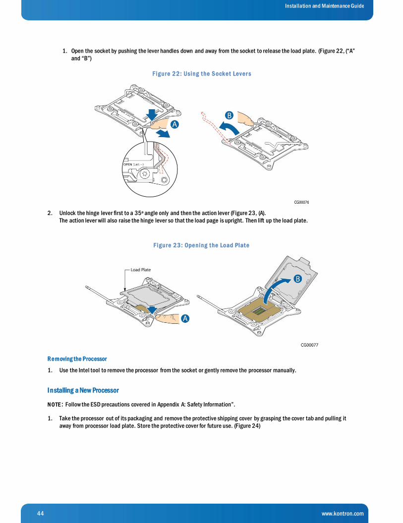
44 www.kontron.com
Installation and Maintenance Guide
1. Open the socket by pushing the lever handles down and away from the socket to release the load plate. (Figure 22, (“A”
and “B”)
F ig ur e 2 2 : Using t he S ock e t Le v e r s
2. Unlock the hinge lever first to a 35º angle only and then the action lever (Figure 23, (A).
The action lever will also raise the hinge lever so that the load page is upright. Then lift up the load plate.
F ig ur e 2 3 : Ope ning t he Load Plat e
Re moving the Processor
1. Use the Intel tool to remove the processor from the socket or gently remove the processor manually.
I nstalling a New Processor
N O TE: Follow the ESD precautions covered in Appendix A: Safety Information”.
1. Take the processor out of its packaging and remove the protective shipping cover by grasping the cover tab and pulling it
away from processor load plate. Store the protective cover for future use. (Figure 24)
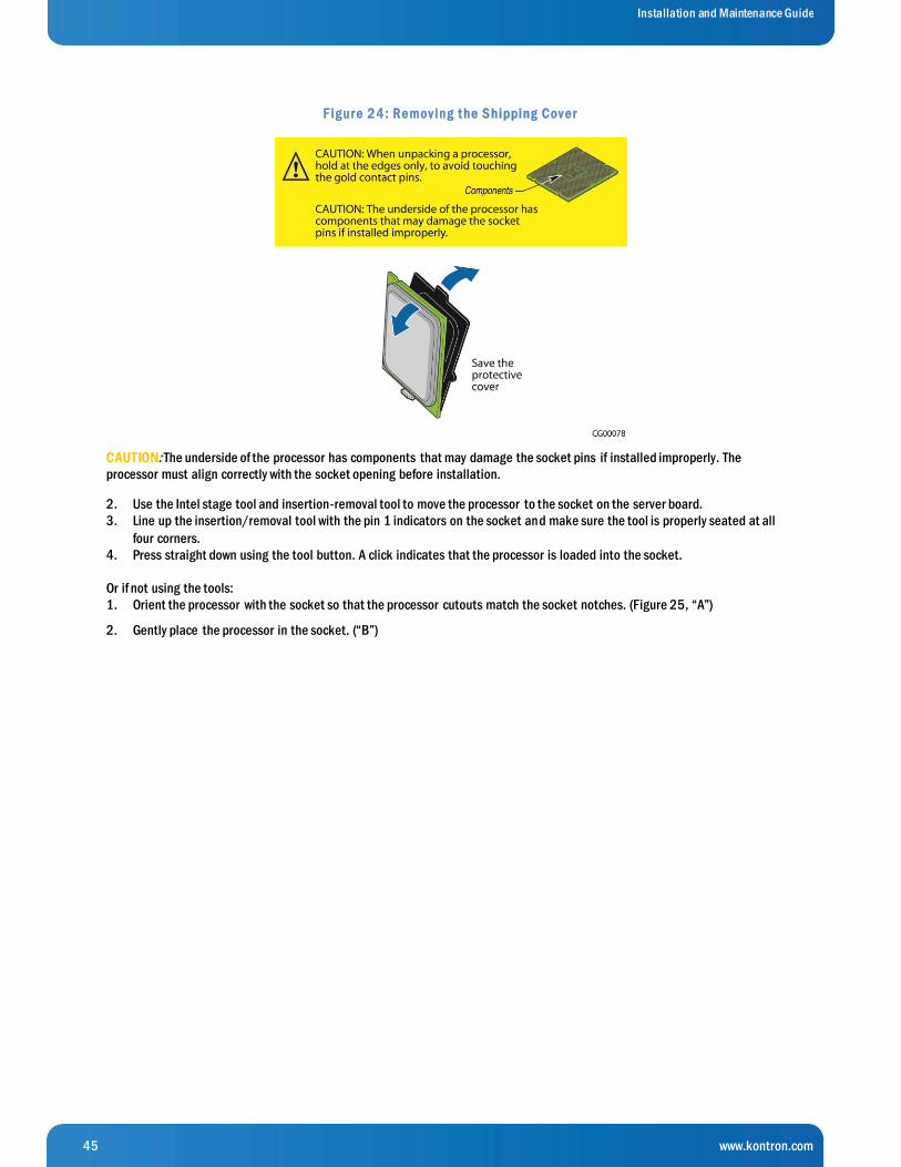
45 www.kontron.com
Installation and Maintenance Guide
F ig ur e 2 4 : Re mov ing t he S hipping Cov e r
CAUTION: The underside of the processor has components that may damage the socket pins if installed improperly. The
processor must align correctly with the socket opening before installation.
2. Use the Intel stage tool and insertion-removal tool to move the processor to the socket on the server board.
3. Line up the insertion/removal tool with the pin 1 indicators on the socket and make sure the tool is properly seated at all
four corners.
4. Press straight down using the tool button. A click indicates that the processor is loaded into the socket.
Or if not using the tools:
1. Orient the processor with the socket so that the processor cutouts match the socket notches. (Figure 25, “A”)
2. Gently place the processor in the socket. (“B”)

46 www.kontron.com
Installation and Maintenance Guide
F ig ur e 2 5 : Manual ly Inst al l ing t he Pr oce ssor in t he S ock e t
3. Carefully close the load plate.
4. Close the hinge socket lever and ensure that the load plate tab engages under the socket lever when fully closed. (Figure 26
“B”)
F ig ur e 2 6 : Closing t he Pr oce ssor Load Plat e
5. When the load plate comes down and the lever is latched, the socket cover pops off. Save it for future use if the processor i s
removed from the socket or for protection if the server is moved or shipped. (Figure 27 “A” and “B”)

47 www.kontron.com
Installation and Maintenance Guide
F ig ur e 2 7 : Closing t he Last S ock e t Le v e r
5.2.5 Installing a Heat Sink
1. If this is a new heat sink (not one removed to add/replace a processor), remove the protective film, if present, on the Thermal
Interface Material (TIM) located on the bottom of the heat sink. (Figure 28, “A”)
2. Set the heat sink over the processor, lining up the four captive screws with the four socket posts surrounding the processor.
Align the heat sink fins to the front and back of the chassis for correct airflow (front to back). (See Figure 28)
3. Loosely screw in the captive screws on the heat sink corners by tightening one, then the one diagonall y opposite, and so on.
(“B”)
4. Gradually and equally tighten each captive screw in diagonal order until each one is firmly tightened. See Figure 28 for the
order.
CAUT ION: the torque spec for these screws is 8 inch pounds. Be careful not to exceed it.

48 www.kontron.com
Installation and Maintenance Guide
F ig ur e 2 8 : Inst al l ing a He at S ink
5.2.6 Configuring Jumpers on the Server Board
The jumpers are located on the S2600CW2SK server board.
Before you can work with the jumpers defined in this section, you must first remove the chassis cover, right riser card assembly
and processor air duct. For instructions, see (A), (B2) and (C) in Chapter 4.
The other components on the server board can remain in place.
The server board has several 3-pin jumper blocks that can be used to configure, protect, or recover specific features of the server
board. This section shows the jumper blocks available and what they do. For detailed information about using these jumpers, see
Sections 7.4 through 7.8.
Pin 1 on each jumper block is identified by this symbol on the silkscreen: ▼
Figure 29 shows the jumper blocks.

49 www.kontron.com
Installation and Maintenance Guide
F ig ur e 2 9 : Jumpe r Block s (J1 B1 , J1 F 3 , J1 F 5 , J1 F 4 , J1 F 6 )
Table 2 : S e r v e r Boar d Jumpe r s ( J1 F 5 , J1 B1 , J1 F 3 , J1 F 4 , J1 F 6 )
J u mper Name Pi ns Sys tem Results
J1F5: Password Clear 1 - 2 These pins should have a jumper in place for normal system operation (Default)
2 - 3 To clear administrator and user passwords, power on the system with pins 2 – 3
connected. The administrator and user passwords clear in 5 – 10 seconds after power
on. Pins 2 – 3 should not be connected for normal system operation.
J1B1: B M C
Force Update
1 - 2 BMC Firmware Force Update Mode – Disabled (Default)
2 - 3 BMC Firmware Force Update Mode – Enabled
J1F3: M E
Force Update
1 - 2 ME Firmware Force Update Mode – Disabled (Default)
2 - 3 ME Firmware Force Update Mode – Enabled
J1F4: B I OS Recovery 1 - 2 These pins should have a jumper in place for normal system operation (Default)
2 - 3 The main system BIOS does not boot with pins 2 – 3 connected. The system only boots
from EFI-bootable recovery media with the recovery BIOS image.
J1F6: B I OS Default
(CMOS Clear)
1 - 2 These pins should have a jumper in place for normal system operation (Default)
2 - 3 If these pins are connected when AC power is unplugged, the CMOS settings are cleared
within five seconds. Pins 2 - 3 should not be connected for normal operation.
See Section 9.1, “BIOS Defaults (CMOS Clear) and Password Reset Usage Procedure” in the Intel® Server Board S2600CW2SK Family TPS on the Kontron Support website for more information about the recovery features.

50 www.kontron.com
Installation and Maintenance Guide
5.2.7 Installing a Hardware RAID Controller
Hard disk drives are supported with SAS software RAID 0/1/10 on the CG2300 server by default. Hardware RAID support
requires a separately-orderable SAS hardware RAID controller, which is described in this section.
N O TE: The components used as examples in this section are from the Intel® RS3DC080 hardware.
Figure 30 shows the SAS hardware RAID controller board layout. The board’s gold edge connector attaches to a header on the
baseboard as shown in Figure 31.
F ig ur e 3 0 : Har dwar e RAID Adapt e r Lay out
Before you can install the hardware RAID controller board, you must first remove the chassis cover and the left riser card
assembly. For instructions, see (A) and (B1) in Chapter 4.
Then, disconnect the two SAS cables (SFF-8643 ends) from the baseboard connector (SGPI01) where they are used for default
software RAID. For instructions, see (E4) in Chapter 4.
To install the hardware RAID controller board, follow these steps:
1. Remove the bracket from the chassis rear panel.
2. Fasten the bracket from the chassis to the RAID controller board, using the two screws in the kit. (Figure 31, “A”)
3. Connect the SAS 1 cable end labeled SFF-8643 into the proper connector (right) on the RAID controller board. ( “B”)
4. Connect the SAS 2 cable end labeled SFF-8643 into the proper connector (left). (“B”)
5. Insert the hardware RAID controller board in the PCIe slot 3 on the baseboard and press down to mate it with the
header. (“D”)
6. Re-install the riser card assembly and the chassis cover. For instructions, see (RK) and (RL) in Chapter 6.
7. If this is the last task you are performing, plug in the power cord(s) and re-connect any peripheral devices.
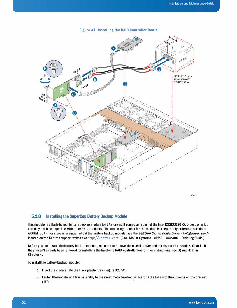
51 www.kontron.com
Installation and Maintenance Guide
F ig ur e 3 1 : Inst al l ing t he RAID Cont r ol le r Boar d
5.2.8 Installing the SuperCap Battery Backup Module
This module is a flash-based battery backup module for SAS drives. It comes as a part of the Intel RS3DC080 RAID controller kit
and may not be compatible with other RAID products. The mounting bracket for the module is a separately orderable part (Intel
AXXRMFBU4). For more information about the battery backup module, see the CG2300 Carrier Grade Server Configuration Guide
located on the Kontron support website at http://kontron.com. (Rack Mount Systems - CRMS – CG2300 – Ordering Guide.)
Before you can install the battery backup module, you need to remove the chassis cover and left riser card assembly. (That is, if
they haven’t already been removed for installing the hardware RAID controller board). For instructions, see (A) and (B1) in
Chapter 4.
To install the battery backup module:
1. Insert the module into the black plastic tray. (Figure 32, “A”)
2. Fasten the module and tray assembly to the sheet metal bracket by inserting the tabs into the cut -outs on the bracket.
(“B”)

52 www.kontron.com
Installation and Maintenance Guide
3. Holding the locking lever on the plastic tray out, slide the module/tray assembly towards the back of the bracket until it
locks into place.
F ig ur e 3 2 : S e t t ing Up t he Bat t e r y Back up Asse mbly
4. Connect the signal/power pigtail cable to the proper connector on the hardware RAID controller board (“C”) and the
rear of the battery backup assembly. (Figure 31, “F”)
5. Place the battery backup bracket on the support cross bar, lining it up with the center hole on the middle shelf. (“G”)
6. Use the blue retention screw to fasten the battery backup assembly bracket to the cross bar.
7. Re-install the left-side riser card assembly and the chassis cover. For instructions, see (RK) and (RL) in Chapter 6.
8. If this is the last task you are performing, plug in the power cord(s) and re-attach any peripheral devices.
5.2.9 Installing a PCIe Riser Card
The CG2300 server does not ship with any PCI riser cards, just the sheet metal brackets where the riser cards and PCI add-in
cards are housed. The S2600CW2SK server board has two riser slots capable of supporting riser cards on the right side and left
side of the chassis. Baseboard PCIe slot 2 (left side) and PCIe slot 6 (right side) support the riser cards in the CG2300 system.
Baseboard PCIe slot 2 supports a single slot PCIe X16 riser or a dual slot PCIe X8 riser. These risers are referred to as the ‘left’
risers since the boards plug in on the left side of the chassis as viewed from the front of the server. PCIe riser cards in slot 2
connect to CPU2. Baseboard PCIe slot 6 supports a single slot PCIe X16 riser or a dual slot PCIe X8 riser. These risers are
referred to as the ‘right‘ risers since the boards plug in on the right side of the chassis. PCIe riser cards in slot 2 connect to CPU1.
Table 3 identifies the card configurations and the connector types used.
Once PCIe add-in cards are installed and the riser card assembly is remounted in the chassis, the cards are accessible from the
rear of the server chassis.
Table 3 identifies the card configurations and the connector types used.
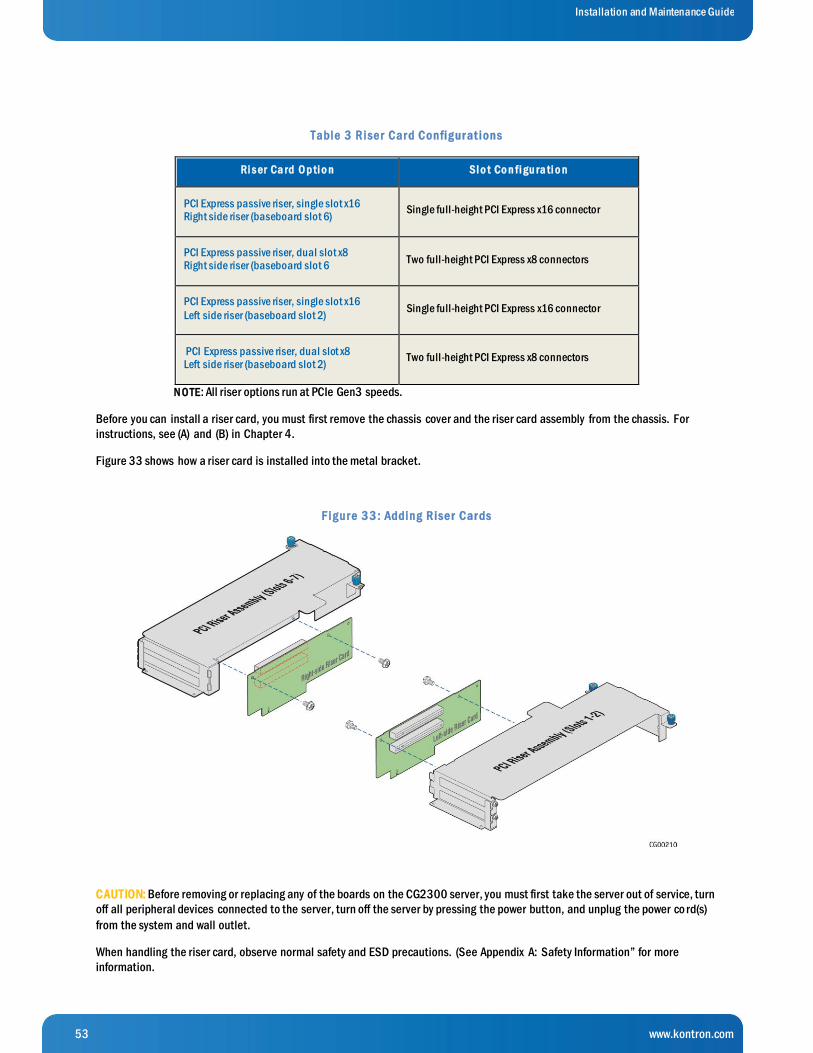
53 www.kontron.com
Installation and Maintenance Guide
Table 3 Rise r Car d Config ur at ions
Ri s er Ca rd O p ti o n Sl o t Co n fi gu ra ti o n
PCI Express passive riser, single slot x16 Right side riser (baseboard slot 6)
Single full-height PCI Express x16 connector
PCI Express passive riser, dual slot x8 Right side riser (baseboard slot 6
Two full-height PCI Express x8 connectors
PCI Express passive riser, single slot x16
Left side riser (baseboard slot 2) Single full-height PCI Express x16 connector
PCI Express passive riser, dual slot x8 Left side riser (baseboard slot 2)
Two full-height PCI Express x8 connectors
N O TE: All riser options run at PCIe Gen3 speeds.
Before you can install a riser card, you must first remove the chassis cover and the riser card assembly from the chassis. For
instructions, see (A) and (B) in Chapter 4.
Figure 33 shows how a riser card is installed into the metal bracket.
F ig ur e 3 3 : Adding Rise r Car ds
CAUTION: Before removing or replacing any of the boards on the CG2300 server, you must first take the server out of service, turn
off all peripheral devices connected to the server, turn off the server by pressing the power button, and unplug the power co rd(s)
from the system and wall outlet.
When handling the riser card, observe normal safety and ESD precautions. (See Appendix A: Safety Information” for more
information.
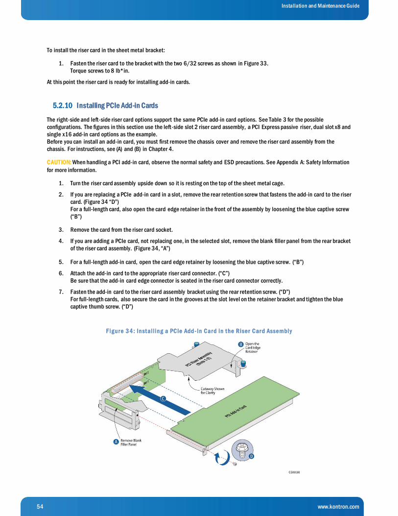
54 www.kontron.com
Installation and Maintenance Guide
To install the riser card in the sheet metal bracket:
1. Fasten the riser card to the bracket with the two 6/32 screws as shown in Figure 33.
Torque screws to 8 lb*in.
At this point the riser card is ready for installing add-in cards.
5.2.10 Installing PCIe Add-in Cards
The right-side and left-side riser card options support the same PCIe add-in card options. See Table 3 for the possible
configurations. The figures in this section use the left-side slot 2 riser card assembly, a PCI Express passive riser, dual slot x8 and
single x16 add-in card options as the example.
Before you can install an add-in card, you must first remove the chassis cover and remove the riser card assembly from the
chassis. For instructions, see (A) and (B) in Chapter 4.
CAUTION: When handling a PCI add-in card, observe the normal safety and ESD precautions. See Appendix A: Safety Information
for more information.
1. Turn the riser card assembly upside down so it is resting on the top of the sheet metal cage.
2. If you are replacing a PCIe add-in card in a slot, remove the rear retention screw that fastens the add-in card to the riser
card. (Figure 34 “D”)
For a full-length card, also open the card edge retainer in the front of the assembly by loosening the blue captive screw
(“B”)
3. Remove the card from the riser card socket.
4. If you are adding a PCIe card, not replacing one, in the selected slot, remove the blank filler panel from the rear bracket
of the riser card assembly. (Figure 34, “A”)
5. For a full-length add-in card, open the card edge retainer by loosening the blue captive screw. (“B”)
6. Attach the add-in card to the appropriate riser card connector. (“C”)
Be sure that the add-in card edge connector is seated in the riser card connector correctly.
7. Fasten the add-in card to the riser card assembly bracket using the rear retention screw. (“D”)
For full-length cards, also secure the card in the grooves at the slot level on the retainer bracket and tighten the blue
captive thumb screw. (“D”)
F ig ur e 3 4 : Inst al l ing a PCIe Add- In Car d in t he Rise r Car d Asse mbly
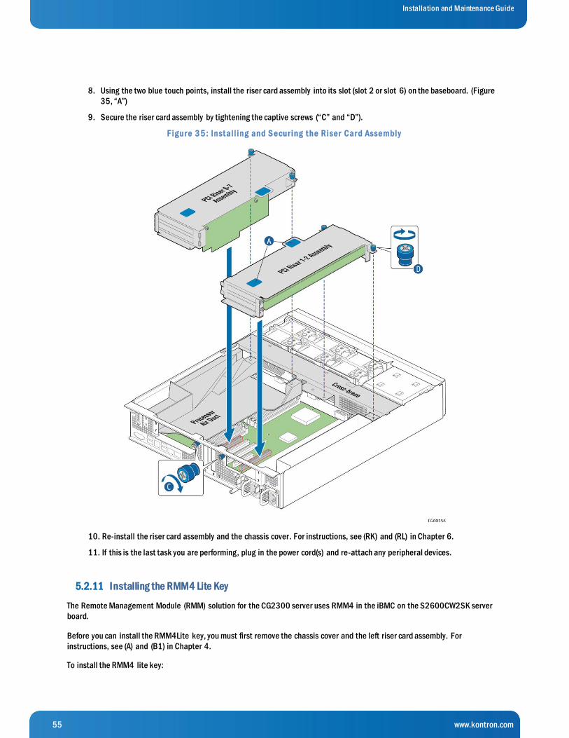
55 www.kontron.com
Installation and Maintenance Guide
8. Using the two blue touch points, install the riser card assembly into its slot (slot 2 or slot 6) on the baseboard. (Figure
35, “A”)
9. Secure the riser card assembly by tightening the captive screws (“C” and “D”).
F ig ur e 3 5 : Inst al l ing and S e cur ing t he Rise r Car d Asse mbly
10. Re-install the riser card assembly and the chassis cover. For instructions, see (RK) and (RL) in Chapter 6.
11. If this is the last task you are performing, plug in the power cord(s) and re-attach any peripheral devices.
5.2.11 Installing the RMM4 Lite Key
The Remote Management Module (RMM) solution for the CG2300 server uses RMM4 in the iBMC on the S2600CW2SK server
board.
Before you can install the RMM4Lite key, you must first remove the chassis cover and the left riser card assembly. For
instructions, see (A) and (B1) in Chapter 4.
To install the RMM4 lite key:

56 www.kontron.com
Installation and Maintenance Guide
1. Press the key into the socket on the baseboard. (Figure 36, “A”)
F ig ur e 3 6 : Inst al l ing t he RMM4 K e y
2. Re-install the left-side riser card assembly and the chassis cover. For instructions, see (RK) and (RL) in Chapter 6
3. If this is the last task you are performing plug in the power cord(s) and re-attach any peripheral devices
5.2.12 Installing an M.2 Storage Drive
A separately purchased, optional M.2 flash drive provides SATA storage. The M.2 flash drive is installed on the S2600CW2SK
server board.
Before you can install an M.2 flash drive, you must first remove the chassis cover and the left riser card assembly. For
instructions, see (A) and (B1) in Chapter 4.
To install the M.2 flash drive card:
1. Connect the M.2 card to the header on the baseboard near the CMOS battery. (Figure 37, “A”)
2. Seat the other end of the M.2 card around the post on the baseboard.
3. Secure the M.2 card by fastening the screw in the post. (“B”)
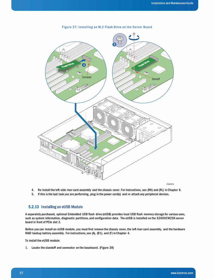
57 www.kontron.com
Installation and Maintenance Guide
F ig ur e 3 7 : Inst al l ing an M.2 F lash Dr iv e on t he S e r v e r Boar d
4. Re-install the left-side riser card assembly and the chassis cover. For instructions, see (RK) and (RL) in Chapter 6.
5. If this is the last task you are performing, plug in the power cord(s) and re-attach any peripheral devices.
5.2.13 Installing an eUSB Module
A separately purchased, optional Embedded USB flash drive (eUSB) provides local USB flash memory storage for various uses,
such as system information, diagnostic partitions, and configuration data. The eUSB is installed on the S2600CW2SK server
board in front of PCIe slot 3.
Before you can install an eUSB module, you must first remove the chassis cover, the left riser card assembly, and the hardware
RAID backup battery assembly. For instructions, see (A), (B1), and (F) in Chapter 4.
To install the eUSB module:
1. Locate the standoff and connector on the baseboard. (Figure 38)
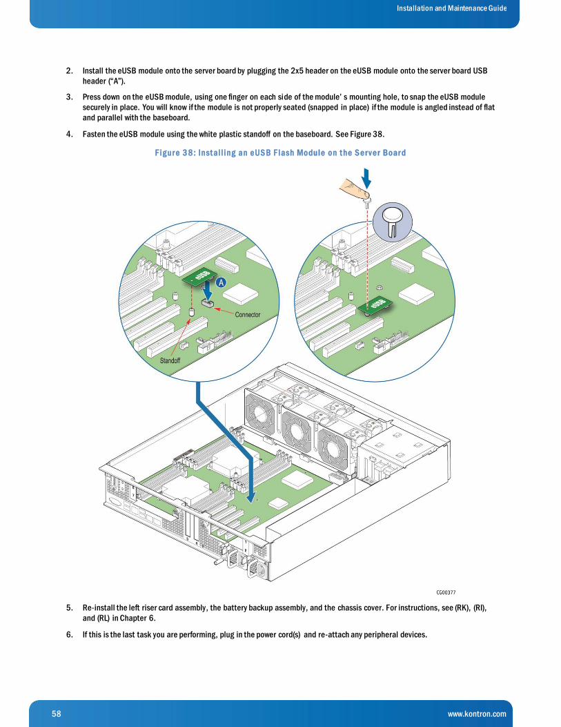
58 www.kontron.com
Installation and Maintenance Guide
2. Install the eUSB module onto the server board by plugging the 2x5 header on the eUSB module onto the server board USB
header (“A”).
3. Press down on the eUSB module, using one finger on each side of the module’ s mounting hole, to snap the eUSB module
securely in place. You will know if the module is not properly seated (snapped in place) if the module is angled instead of flat
and parallel with the baseboard.
4. Fasten the eUSB module using the white plastic standoff on the baseboard. See Figure 38.
F ig ur e 3 8 : Inst al l ing an e US B F lash Module on t he S e r v e r Boar d
5. Re-install the left riser card assembly, the battery backup assembly, and the chassis cover. For instructions, see (RK), (RI),
and (RL) in Chapter 6.
6. If this is the last task you are performing, plug in the power cord(s) and re-attach any peripheral devices.
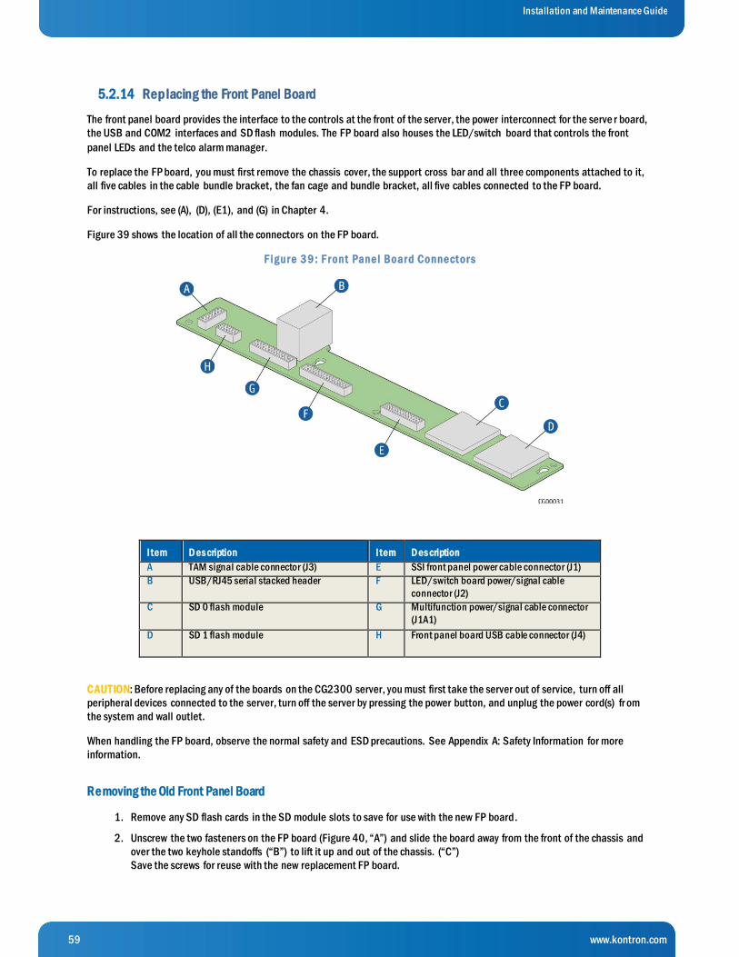
59 www.kontron.com
Installation and Maintenance Guide
5.2.14 Replacing the Front Panel Board
The front panel board provides the interface to the controls at the front of the server, the power interconnect for the serve r board,
the USB and COM2 interfaces and SD flash modules. The FP board also houses the LED/switch board that controls the front
panel LEDs and the telco alarm manager.
To replace the FP board, you must first remove the chassis cover, the support cross bar and all three components attached to it,
all five cables in the cable bundle bracket, the fan cage and bundle bracket, all five cables connected to the FP board.
For instructions, see (A), (D), (E1), and (G) in Chapter 4.
Figure 39 shows the location of all the connectors on the FP board.
F ig ur e 3 9 : F r ont Pane l Boar d Conne ct or s
I tem D es cription I tem D es cription
A TAM signal cable connector (J3) E SSI front panel power cable connector (J1)
B USB/RJ45 serial stacked header F LED/switch board power/signal cable
connector (J2)
C SD 0 flash module
G Multifunction power/signal cable connector
(J1A1)
D SD 1 flash module
H Front panel board USB cable connector (J4)
CAUTION: Before replacing any of the boards on the CG2300 server, you must first take the server out of service, turn off all
peripheral devices connected to the server, turn off the server by pressing the power button, and unplug the power cord(s) fr om
the system and wall outlet.
When handling the FP board, observe the normal safety and ESD precautions. See Appendix A: Safety Information for more
information.
Removing the Old Front Panel Board
1. Remove any SD flash cards in the SD module slots to save for use with the new FP board.
2. Unscrew the two fasteners on the FP board (Figure 40, “A”) and slide the board away from the front of the chassis and
over the two keyhole standoffs (“B”) to lift it up and out of the chassis. (“C”)
Save the screws for reuse with the new replacement FP board.
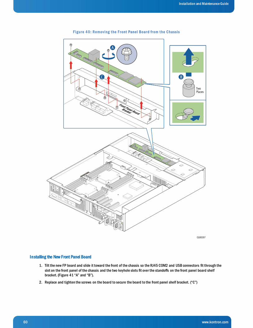
60 www.kontron.com
Installation and Maintenance Guide
F ig ur e 4 0 : Re mov ing t he F r ont Pane l Boar d fr om t he Chassis
I nstalling the New Front Panel Board
1. Tilt the new FP board and slide it toward the front of the chassis so the RJ45 COM2 and USB connectors fit through the
slot on the front panel of the chassis and the two keyhole slots fit over the standoffs on the front panel board shelf
bracket. (Figure 41 “A” and “B”).
2. Replace and tighten the screws on the board to secure the board to the front panel shelf bracket. (“C”)
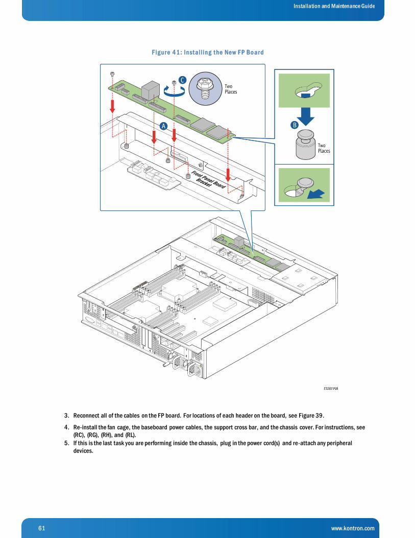
61 www.kontron.com
Installation and Maintenance Guide
F ig ur e 4 1 : Inst al l ing t he Ne w F P Bo ar d
3. Reconnect all of the cables on the FP board. For locations of each header on the board, see Figure 39.
4. Re-install the fan cage, the baseboard power cables, the support cross bar, and the chassis cover. For instructions, see
(RC), (RG), (RH), and (RL).
5. If this is the last task you are performing inside the chassis, plug in the power cord(s) and re-attach any peripheral
devices.

62 www.kontron.com
Installation and Maintenance Guide
5.2.15 Replacing the LED/Switch Board
The LED/switch board is mounted against the front panel of the CG2300 server chassis because it supports the LEDs and
switches that are on the control panel on the front of the chassis.
Before you can replace the LED/switch board, you must first remove the chassis cover, the front bezel, and the fan cage so you
can access the board from the back. You may also have to loosen the front panel board and slide it back, in order to access t he
LED/switch board retaining screw. For instructions, see (A), (I), and (G) in Chapter 4.
Removing the Old LED/Switch Board
To remove the LED/Switch board:
1. Disconnect the multifunction cable on the FP board so there is enough room to unfasten the retainer screw on the top
right side of the LED/switch board.
If there is not enough room to access this screw, remove (or at least slide back) the FP board. For instructions, see
“Removing the Old Front Panel Board” in Section 5.2.14.
2. The LED/switch board is also attached to the front of the chassis by two standoffs. Once the retaining screw is
removed, pry the LED/switch board loose from these standoffs to remove it.
Replacing the LED/Switch Light Pipe Assembly
1. Remove the black control panel module from the front of the chassis by lifting up from the bottom and then pulling
down to release the top tabs holding it into the chassis frame.
2. Position the new control panel module with the top tabs in the appropriate slots. Gently push down and in to secure the
bottom of the panel in order to attach it to the LED/switch board.
I nstalling the New LED/Switch Board
1. Connect the LED/switch board power and signal ribbon cable to the new LED/switch board.
2. Align the left side of the LED/switch board with the two standoffs on the inside of the front panel of the chassis and
gently push the board to secure it to the chassis frame.
3. Fasten the screw at the right of the LED/switch board to hold the board in place.
4. Replace the front panel board if you removed it or slid it out to work on the LED/switch board installation. For
instructions, see “Installing the New Front Panel Board” in Section 5.2.14.
5. Re-connect the multifunction cable on the FP board.
6. Re-install the fan cage, the baseboard power cables, the front bezel, and the chassis cover. For instructions, see (RC),
(RG), (RA), and (RL) in Chapter 6
7. If this is the last task you are performing inside the server chassis, plug in the power cord(s) and re-attach any
peripheral devices.
5.2.16 Replacing the Telco Alarms Module (TAM) Board
The TAM board is on the right side of the CG2300 server chassis floor, just below the front panel. Before you can replace th e TAM
board, you must first remove the chassis cover, the support cross bar, the baseboard power cables, and the fan cage. (You do not
have to remove the front panel board in order to access the TAM board). For instructions, see (A), (D), (E1), and (G)
CAUTION: Before replacing any of the boards on the CG2300 server, first take the server out of service, turn off all peripheral
devices connected to the server, turn off the server by pressing the power button, and unplug the power cord(s) from the syst em
and wall outlet.

63 www.kontron.com
Installation and Maintenance Guide
When handling the TAM board, observe normal safety and ESD precautions. (See Appendix A: Safety Information” for more
information.
Removing the Old TAM Board
To remove the TAM board:
1. Unfasten the two retaining screws from the front of the chassis. (Figure 42)
2. Disconnect the TAM signal cable that is connected to the FP board. (Figure 42)
3. Disconnect the alarms cable that is routed to the rear of the chassis. (Figure 42)
4. Remove the TAM board from the chassis by pulling it away from the front panel of the chassis. (Figure 42)
F ig ur e 4 2 : Re mov ing t he TAM Boar d
I nstalling the New TAM Board
1. Slide the new TAM board toward the front panel and align it with the two holes for the retaining screws. (Figure 42)
2. Fasten the retaining screws from the front panel of the chassis to hold the board in place. (Figure 42)
3. Connect the alarms cable from the FP board to the TAM board. (Figure 42)
4. Connect the alarms cable from the rear of the chassis to the TAM board. (Figure 42)
5. Re-install front bezel, the fan cage, the baseboard power cables, the support cross bar, and the chassis cover. For
instructions, see (RA), (RC), (RG), (RH), and (RL) in Chapter 6.
6. If this is the last task you are performing inside the server chassis, plug in the power cord(s) and re-attach any
peripheral devices.
5.2.17 Replacing the Fan Control Board (FCB)
The fan control board is located on the chassis floor in front of the server board and just behind the fan cage and the cable tray.
The fan control functions are controlled by the fan controller IC. This controller monitors the “Fan Present” signals from ea ch of
the fan positions, drives the “Fan PWM” signals, monitors the “Fan Tach” signals, and drives the “Fan Fail” signals. Fan speed is
controlled using temperature sensors located on the server board. When a fan fault is detected the fan controller drives the “Fan
64 www.kontron.com
Installation and Maintenance Guide
Fault” signal “ON” in the fault LED on the fan assembly. Simultaneously, a composite fan fault LED, visible at the chassis front
bezel, is turned “ON” on the front panel LED board.
Before you can replace the fan control board, you need to remove the chassis cover, the support cross bar (and all components
attached to it), the baseboard power cables, the fan cage and the FCB cables. For instructions, see (A), (D), (E1), (G), and (E5) in
Chapter 4.
Removing the Old FCB
To remove the fan control board from the chassis:
Three fan cables for the fan pairs (if not already disconnected when removing the fan cage) 1.
Unfasten the five screws on the fan control board that fasten it to the chassis floor. See Figure 43 for the locations of these 2.
screws. Save the screws to use when installing the new fan control board.
Lift the fan control board out of the chassis. 3.
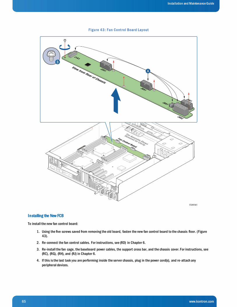
65 www.kontron.com
Installation and Maintenance Guide
F ig ur e 4 3 : F an Cont r ol Boar d Lay out
I nstalling the New FCB
To install the new fan control board:
1. Using the five screws saved from removing the old board, fasten the new fan control board to the chassis floor. (Figure
43).
2. Re-connect the fan control cables. For instructions, see (RD) in Chapter 6.
3. Re-install the fan cage, the baseboard power cables, the support cross bar, and the chassis cover. For instructions, see
(RC), (RG), (RH), and (RJ) in Chapter 6.
4. If this is the last task you are performing inside the server chassis, plug in the power cord(s), and re-attach any
peripheral devices.
66 www.kontron.com
Installation and Maintenance Guide
5.2.18 Replacing the Power Distribution Board (PDB)
The power distribution board (PDB) routes power from the power supply module(s) to the rest of the server through an integral
wiring harness.
To replace the PDB, first remove the following components:
Top cover »
Support cross bar and all components attached to it »
SAS HDD backplane board »
All cables from the PDB at the connections on the other end (The cables are soldered onto the PDB and the new board »
has a new set of cables attached.)
Baseboard SSI main power cable (from the 24-pin connector on the baseboard; bundle soldered on the PDB) »
CPU and DIMM power cables (one for each CPU, from the 8-pin connectors on the baseboard; soldered on »
the PDB)
Fan control board power cable (from the 12-pin connector on the fan control board, soldered on the PDB) »
HDD backplane board power cable (from the HSBP board, soldered on the PDB) »
Auxiliary I/O power dongle (from any auxiliary PCI adapters installed and routed out of the PCI air baffle, »
soldered on the PDB)
Baseboard SSI power control signal cable (from the baseboard, soldered on the PDB) »
For instructions, see (A), (D), (H), (E1), (E5), and (E4) in Chapter 4.
Refer to Figure 12: Cable Routing” and Table 1: Cable Connections” for the location of the connectors where each cable is
disconnected.
CAUTION: Before replacing any of the boards on the CG2300 server, first take the server out of service, turn off all peripheral
devices connected to the server, turn off the server by pressing the power button, and unplug the power cord(s) from the syst em
and wall outlet.
When handling the power distribution board, observe the normal safety and ESD precautions. See Appendix A: Safety Information
for more information.
Removing the Old PDB
1. Slide the power supply module(s) out a few inches to disengage it from the PDB.
2. Loosen the two screws that secure the PDB bracket to the chassis and save them for re-installing the new PDB assembly.
(Figure 44, “A”)
3. Gently pull the PDB and all its attached cables out of the chassis. (“B”).
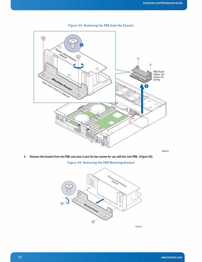
67 www.kontron.com
Installation and Maintenance Guide
F ig ur e 4 4 : Re mov ing t he PDB fr om t he Chassis
4. Remove the bracket from the PDB and save it and the two screws for use with the new PDB. (Figure 45)
F ig ur e 4 5 : Re mov ing t he PDB Mount ing Br ack e t
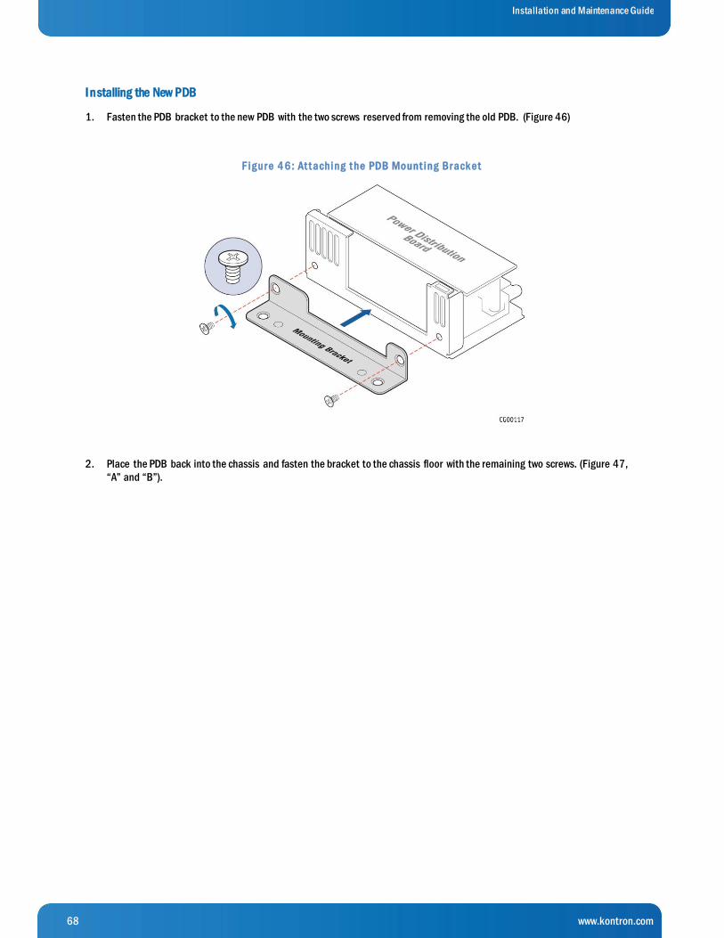
68 www.kontron.com
Installation and Maintenance Guide
I nstalling the New PDB
1. Fasten the PDB bracket to the new PDB with the two screws reserved from removing the old PDB. (Figure 46)
F ig ur e 4 6 : At t aching t he PDB Mount ing Br ack e t
2. Place the PDB back into the chassis and fasten the bracket to the chassis floor with the remaining two screws. (Figure 47,
“A” and “B”).

69 www.kontron.com
Installation and Maintenance Guide
F ig ur e 4 7 : Inst al l ing t he Ne w PDB in t he Chassis
3. Connect all of the new cables on the new PDB to their connectors on the SAS backplane, server board, and fan control
board, being careful to route them as low as possible so as not to interfere with other components or air flow. For
instructions, see (RE), (RG), and (RD) in Chapter 6.
4. Place the new auxiliary I/O cable/dongle in the PCI air baffle and re-attach the baffle to the side wall of the chassis. (Figure
47, “C” and “D”)
5. Re-install the SAS HDD backplane board and surrounding air baffle, the support cross bar, and the chassis cover. For
instructions, see (RB), (RH) and (RL) in Chapter 6.
6. Push the power supply module(s) back into place so they are mated with the PDB.
7. If this is the last task you are performing inside the server chassis, plug in the power cord(s), and re-attach any peripheral
devices.

70 www.kontron.com
Installation and Maintenance Guide
5.2.19 Replacing the S2600CW2SK Server Board
The CG2300 Carrier Grade Server uses the Intel® server board S2600CW2SK. To replace the server board, the following
components must be removed first:
Top chassis cover »
Riser card assemblies »
Processor air duct »
RMM4Lite key (if used) »
Hardware RAID controller board (if used) »
SuperCap battery backup (if used) »
eUSB module (if used) »
.M. 2 module (if used) »
Support cross bar »
All cables attached to the baseboard: »
Baseboard power cables »
Baseboard signal cables »
Fan I2C cable »
Front panel board USB cable »
SAS 1 cable and SAS 2 cable (which will be on baseboard or the hardware RAID board, if used) »
HSBP I2C/HDD LED cable »
For instructions, see (A), (B), (C), (D), (E), and (F) in Chapter 4, and the following other sections:
5.2.7: “Installing a Hardware RAID Controller”, 5.2.11: “Installing the RMM4 Lite Key”, 5.2.12: “Installing an M.2 Storage
Drive”, and 5.2.13: “Installing an eUSB Module”.
In addition, you will probably want to remove the following components for reuse on the replacement server board if it hasn’t
already been populated with spare components:
Heat sink(s) »
Processor(s) »
All DIMMs »
For instructions, see the following sections: “Removing a Heat Sink” and “Removing a Processor” in 5.2.4 and 5.2.3: “Replacing
or Removing Memory DIMMs”.
If you want to reuse components from this server board, you can remove them now or after you have removed the server board
from the chassis.
CAUTION: Before replacing any of the boards on the CG2300 server, first take the server out of service, turn off all peripheral
devices connected to the server, turn off the server by pressing the power button, and unplug the power cord(s) from the syst em
and wall outlet.
When handling the server board, observe the normal safety and ESD precautions. See Appendix A: Safety Information for more
information.
Removing the Old Server Board
1. Loosen all nine screws holding the server board to the chassis and save them for use with the new server board. See
Figure 48 “A” for the location of these screws.
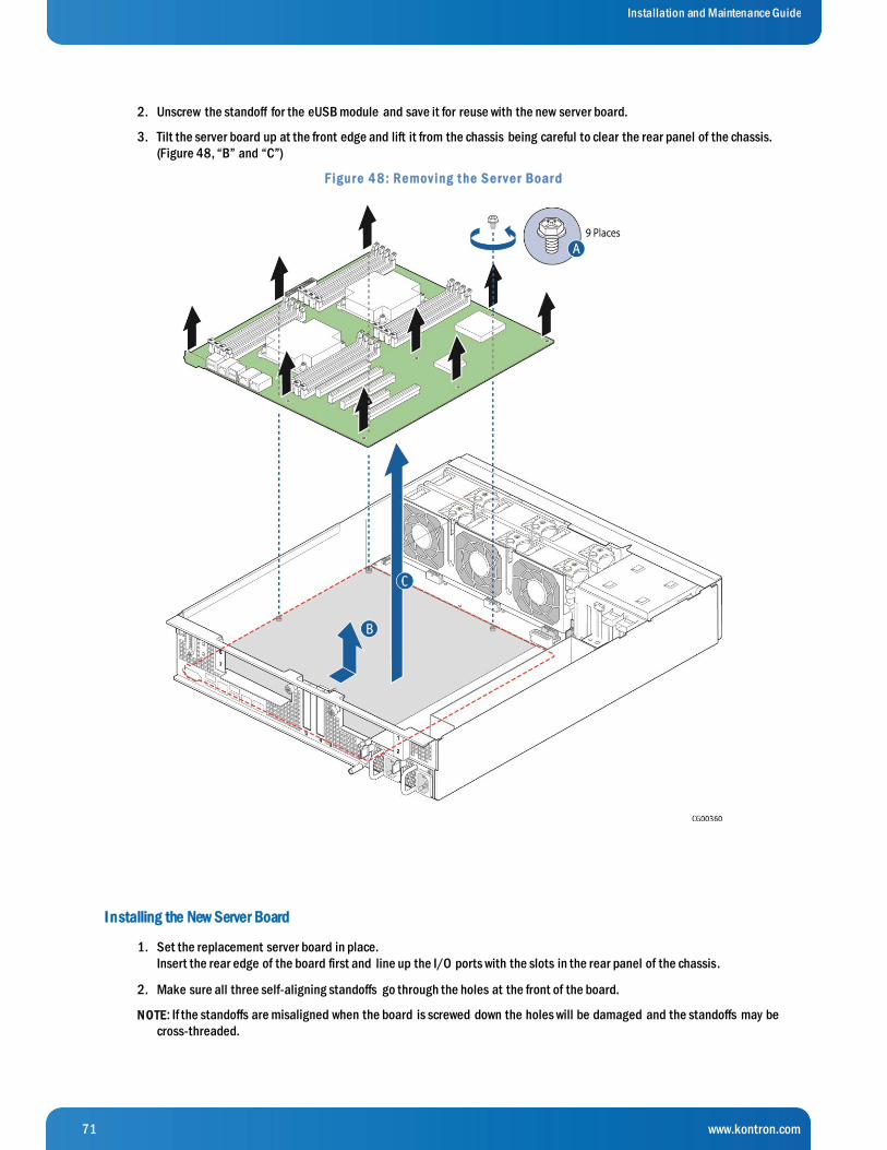
71 www.kontron.com
Installation and Maintenance Guide
2. Unscrew the standoff for the eUSB module and save it for reuse with the new server board.
3. Tilt the server board up at the front edge and lift it from the chassis being careful to clear the rear panel of the chassis.
(Figure 48, “B” and “C”)
F ig ur e 4 8 : Re mov ing t he S e r v e r Boar d
I nstalling the New Server Board
1. Set the replacement server board in place.
Insert the rear edge of the board first and line up the I/O ports with the slots in the rear panel of the chassis.
2. Make sure all three self-aligning standoffs go through the holes at the front of the board.
N O TE: If the standoffs are misaligned when the board is screwed down the holes will be damaged and the standoffs may be
cross-threaded.
72 www.kontron.com
Installation and Maintenance Guide
3. Fasten the server board to the chassis base with the nine screws that were removed and saved.
4. If the new server board does not have components pre-installed and you are re-using components from the old server
board, re-install the memory DIMMs, processor(s), and heat sink(s).
For instructions, see Section 5.2.3 “Replacing or Removing Memory DIMMs”, 5.2.4 “Adding or Replacing a Processor”
and 5.2.5 “Installing a Heat Sink”.
5. Re-install RMM4Lite key, if used, the hardware RAID controller board and battery backup, if used, the eUSB module, if
used, the M.2 flash drive, if used.
For instructions, see 5.2.11 “Installing the RMM4 Lite Key”, 5.2.7 “Installing a Hardware RAID Controller” and 5.2.13
“Installing an eUSB Module”.
6. Re-install all cables disconnected when the old server board was removed, the support cross bar, the processor air
duct, the riser card assemblies, . For instructions, see (RE), (RF), (RG), (RH), (RJ), and (RK) in Chapter 6.
7. Re-connect the TAM alarms cable to the alarms connector on the chassis rear panel. For instructions, see “Installing
the New TAM Board” in 5.2.16.
8. Re-install the chassis cover. For instructions, see (RL) in Chapter 6.
9. If this is the last task you are performing inside the server chassis, plug in the power cord(s), and re-attach any
peripheral devices.
5.2.20 Replacing the SAS Backplane
The six-slot SAS backplane board is located at the rear of the HDD drive bay assembly. It is held in place by a cover plate on top
of the HDD bay assembly that goes over the top edge of the backplane board. There is also a black plastic air duct surrounding
the drive bay on the right side and rear of the assembly.
CAUTION: Before replacing any of the boards on the CG2300 server, first take the server out of service, turn off all peripheral
devices connected to the server, turn off the server by pressing the power button, and unplug the power cord(s) from the system
and wall outlet.
When handling the SAS backplane board, observe the normal safety and ESD precautions. See “Appendix A: Safety Information”
for more information.
Removing the Old SAS Backplane Board
In order to replace the SAS backplane board, you need to first remove the following components: the chassis cover and the fro nt
bezel. For instructions, see (A) and (I) in Chapter 4.
Once the SAS backplane board in accessible, you also need to disconnect the power cable and the two SAS connectors. For
instructions, see (E4) in Chapter 4.
N O TE: The complete procedure for removing the SAS backplane board is covered in (H) in Chapter 4.
1. Once the backplane board is removed and the cables disconnected, remove the HDD air duct from the old backplane
board by loosening the two screws on the backplane. (Figure 49, “A”)
2. Save the air duct to reuse with the new board. (“B”)

73 www.kontron.com
Installation and Maintenance Guide
F ig ur e 4 9 : Re mov ing t he Air Duct fr om t he Back plane Boar d
I nstalling the New SAS Backplane Board
N O TE: The complete procedure for reassembling the backplane board, cables, air duct, and cover plate is (RB) in Chapter 6.
1. Attach the HDD air duct to the new SAS backplane board using the two retained screws. (Figure 50, “A” and “B”))
2. Connect the four cables into the back of the backplane board. Be careful that the HSBP I2C/HDD LED cable does not catch
on the corner of the backplane board or the air duct. For instructions, see (RE) in Chapter 6.
3. Secure the six-slot HDD backplane in place with the cover plate, lock in the hard drives, re-attach the front bezel and the
chassis cover. For instructions, see (RB) in Chapter 6.
4. If this is the last task you are performing inside the server chassis, plug in the power cord(s), and re-attach any peripheral
devices.
F ig ur e 5 0 : Re - At t aching t he Back plane Boar d t o t he Air Duct
5.3 Tasks with the Chassis Closed
The procedures covered in this section all involve hot-swappable components that do not require disconnecting power to the
system or removing the top chassis cover.
74 www.kontron.com
Installation and Maintenance Guide
5.3.1 Adding or Replacing Hard Disk Drives
Up to six hot-swappable SAS hard disk drives can be installed in the CG2300 server. The drives go into carriers that connect to
the SAS backplane board once the carriers with drives attached are inserted back into the drive bay slots. The CG2300 server
ships with six drive carriers.
While you must remove the front bezel to add or replace a hard drive in one of the drive slots, it is not necessary to remove the
chassis cover or to power down the system. The hard drives are hot-swappable.
CAUTION: If you install fewer than six hard disk drives, to maintain proper cooling the unused drive slots must contain the empty
carriers with filler panels that ship with the server.
The CG2300 server does not support all SAS HDD or SATA SSD disk drives. To see a list of validated manufacturers and drive
models, refer to the THOL. The latest version of the THOL is located on the Kontron support website at http://kontron.com.
(Rack Mount Systems - CRMS – CG2300 – Test Hardware and Operating System List (THOL)).
N O TES:
SATA rotating HDDs are not recommended for use in this system because they are sensitive to rotational vibration from system
fan blades.
The complete procedure for adding or replacing hard disk drives is covered in Section 3.1 “Adding or Replacing Hot-Swappable
Hard Disk Drives”.
5.3.2 Adding or Replacing a Power Supply Unit
Adding a Second Power Supply Module
Depending on the model ordered, the server has one AC or one DC power supply module. A second power supply provides
redundancy. The power supply modules are hot-swappable, so no chassis components have to be removed to add or replace a
module. To add a second power supply module:
1. Remove the filler panel by pressing and holding the green safety lock downward and using the handle to pull the filler
panel out of the slot. (Figure 51 “A” and “B”)
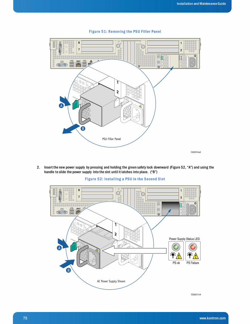
75 www.kontron.com
Installation and Maintenance Guide
F ig ur e 5 1 : Re mov ing t he PS U F i l le r Pane l
2. Insert the new power supply by pressing and holding the green safety lock downward (Figure 52, “A”) and using the
handle to slide the power supply into the slot until it latches into place. (“B”)
F ig ur e 5 2 : Inst al l ing a PS U in t he S e cond S lot

76 www.kontron.com
Installation and Maintenance Guide
3. If you are installing a DC power supply, there are two threaded studs for chassis enclosure grounding.
A 90°standard barrel, two-hole, compression terminal lug with 5/8-inch pitch suitable for a #14-10 AWG conductor
must be used for proper safety grounding. A crimping tool may be needed to secure the terminal lug to the grounding
cable.
F ig ur e 5 3 : DC Powe r S upply Gr ounding
Replacing a Power Supply in Either Slot
Power Supply Units (PSUs) are hot-swappable, but you do need to unplug the power cord from the failed PSU to reconnect it with
the new one. If you are replacing the main PSU and have a redundant PSU in your system, power will switch over to the redund ant
unit while you replace the main unit.
1. Unplug the power cord from the PSU being replaced. The Power Supply Status LED shows which power supply has
failed. (Figure 52)
2. Press and hold the green safety lock downward and using the handle, pull the failed power supply out of the slot.
3. Press and hold the green safety lock downward (“A”) and using the handle, slide the new power supply into the slot
until it latches into place. (“B”)
5.3.3 Installing the Server in a Rack
Several different rack mounting kits are available, depending on whether you need 2 -post or 4-post mounting and whether you
need 19-inch or 23-inch rack widths. Also available are a basic slide rail kit and a rail enabling kit. For detailed information
about the rack mounting kits and how to order them, see the CG2300 Carrier Grade Server Configuration Guide. The latest
version of the Configuration Guide is located on the Kontron support website at http://kontron.com. (Rack Mount Systems -
CRMS – CG2300 - Ordering Guide). Installation instructions are included in each of the rack mounting kits.

77 www.kontron.com
Installation and Maintenance Guide
Connecting the Power Cord
N O TE: When using a rack, wait to install the power cord(s) until after the server is in the rack.
Equipment Rack Precautions
CAUTION: ANCHOR THE EQUIPMENT RACK — The equipment rack must be anchored to an unmovable support to prevent it from
falling over when one or more servers are extended in front of it on slide assemblies. The equipment rack must be installed
according to the manufacturer’s instructions. You must also consider the weight of any other device installed in the rack.
Mains power disconnect — The power cord(s) is considered the mains disconnect for the server and must be readily accessible
when installed. If the individual server power cord(s) will not be readily accessible for disconnection then you are responsi ble for
installing a power disconnect for the entire rack unit. This main disconnect must be readily accessible, and it must be labeled as
controlling power to the entire rack, not just to the server(s). To remove all power, two power cords must be removed.
Gr ounding the rack installation — To avoid the potential for an electrical shock hazard, for AC power you must include a third wire
safety ground conductor with the rack installation. For DC power the two studs for chassis enclosure grounding must be used for
proper safety grounding. See Figure 53in Section 5.3.2, “Adding or Replacing a Power Supply Unit” for the location of the ground
studs. With AC power, if the server power cord is plugged into an outlet that is part of the rack, then you must provide proper
grounding for the rack itself. If the server power cord is plugged into a wall outlet, the safety ground conductor in the power cord
provides proper grounding only for the server. You must provide additional, proper grounding for the rack and other devices
installed in it.
AC ov ercurrent protection — When AC power is used, the server is designed for a line voltage source with up to 20 amperes of
overcurrent protection per cord feed. If the power system for the equipment rack is installed on a branch circuit with more than 20
amperes of protection, you must provide supplemental protection for the server. The overall current rating of a server config ured
with two power supplies is less than 6 amperes.
CAUTION: Temperature — The operating temperature of the server, when installed in an equipment rack, must not go below 5°C
(41°F) or rise above 40°C (104°F) ). Extreme fluctuations in temperature can cause a variety of problems in the server.
5.3.4 Preparing Power Cable
DC power cable
In order to bring power to the unit, a power cable must be built. Each CG2300’s DC Power Supply is shipped with its mating
connector kit. Below is the procedure and details to build the power input cable, using the provided mating connector kit. A video
of the assembly procedure is also available here: https://youtu.be/8JFkm2o0sCk
To order spare DC mating connector kit, please use CG2300’s Ordering/Configuration Guide.
Included in the bag:
Description Quantity
Mating connector/pins housing 1
Housing backshell 1
Connector pin (FC112N2S/AA-15) 3
Strain relief plate 1
Strain relief screws (round head) 2
Backshell screws (flat head) 2

78 www.kontron.com
Installation and Maintenance Guide
Cable S election
The cable must include three wires. Ideally, one red for RTN (+VDC), one black for -VDC and one yellow/green for earth GND.
Kontron recommends 12AWG wires with a minimum 90°Celsius rated insulation. See note below about system’s maximum
current.
Crimping Pins
Cr imping Tool
A crimping tool is needed to properly crimp the pins onto the wire. Positronic 9509-4-0-0 is the hand crimping tools
recommended by the connector’s manufacturer. Other « generic » crimping tools can also be used, such as DMC M22520/1-01
(P/N AF8) or Positronic PN 9501-0-0-0.
Refer to following document to use good crimping practices and not overcrimp the pins:
http://www.connectpositronic.com/?media_dl=58251
Prepare your crimping tool with appropriate settings. As an example, Kontron used a Style-1015 cable (stranded 12AWG, 600V,
VW-1, 105 °Celsius, FT-1 rated insulation) along with the DMC AF8 tool with a setting of 16AWG to get a tensile strength of
approximately 100 pounds. Note that the thickness and number of conductors in wire, the type of material of the conductor, the
plating of the conductor and other characteristics will influence the tensile strength. On the DMC tool, the hole depth setti ng at
16/20 will give the appropriate depth so crimp indents are properly located into pin/contact barrel.
Cr imping Pin Onto Wire
Cut wire to get a flat perpendicular edge.
Remove 5.84 ± 0.51mm (0.230 ± 0.02 inch) of the wire insulator
In case of a stranded cable, twist the strands to fit into the barrel of the contact/pins.
Insert all strands into the barrel. NOTE: this is tight for a 12AWG cable, requiring precise manipulations. A magnifying
glass might help.
Insert the pin/contact (and previously inserted wire) in the hole of the crimp tool.
Crimp the pin/contact by pressing firmly handles of the hand crimp tool.
Repeat for all three wires.
Inspecting the crimped contacts
Make sure the crimped contacts you have just made are meeting these inspection criteria:
Strands are visible through the inspection hole.
Strands not to be visible between the insulation and barrel, i.e insulation finishes when crimp contact barrel starts.
Crimped contact to meet recommended conductor tensile force shown in chart below.
Recommended Conductor Tensile
Strength (Positronic)
Wire Size
(AWG/[mm2])
Axial Load
(Pounds/[N])
12 / [4.0] 110
14 / [4.0] 70
16 / [4.0] 50
Check for peeled gold and bent contacts.
It is also recommended that the crimp indents are located nearly the middle of the barrel, not too close to the
inspection hole nor the other end of the barrel (wire insulation).
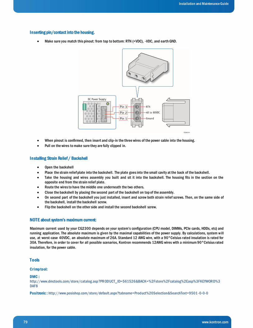
79 www.kontron.com
Installation and Maintenance Guide
I nserting pin/contact into the housing.
Make sure you match this pinout: from top to bottom: RTN (+VDC), -VDC, and earth GND.
When pinout is confirmed, then insert and clip-in the three wires of the power cable into the housing.
Pull on the wires to make sure they are fully clipped in.
I nstalling Strain Relief / Backshell
Open the backshell
Place the strain relief plate into the backshell. The plate goes into the small cavity at the back of the backshell.
Take the housing and wires assembly you built and sit it into the backshell. The housing fits in the section on the
opposite end from the strain relief plate.
Route the wires to have the middle one underneath the two others.
Close the backshell by placing the second part of the backshell on top of the assembly.
On second part of the backshell you just installed, insert and screw both strain relief screws. Then, on the same side of
the backshell, install the backshell screw.
Flip the backshell on the other side and install the second backshell screw.
NOTE about system’s maximum current:
Maximum current used by your CG2300 depends on your system’s configuration (CPU model, DIMMs, PCIe cards, HDDs, etc) and
running application. The absolute maximum is given by the maximal capabilities of the power supply. By calculations, system will
use, at worst-case 40VDC, an absolute maximum of 26A. Standard 12 AWG wire, with a 90°Celsius rated insulation is rated for
30A. Therefore, in order to cover for all possible scenarios, Kontron recommends 12AWG wires with a minimum 90°Celsius rated
insulation, for the power cable.
Tools
Cr imp tool:
DMC :
http://www.dmctools.com/store/catalog.asp?PRODUCT_ID=561526&BACK=%2Fstore%2Fcatalog%2Easp%3FKEYWORD%3
DAF8
Positronic : http://www.posishop.com/store/default.aspx?tabname=Product%20Selection&SearchText=9501 -0-0-0
80 www.kontron.com
Installation and Maintenance Guide
Extraction tool :
Positronic : http://www.posishop.com/store/default.aspx?tabname=Product%20Selection&SearchText=9081 -0-0-0
Positronic Reference Documents:
Removable Contact Tooling Cross Reference: http://www.connectpositronic.com/?media_dl=34147
Strip Length Cross Reference: http://www.connectpositronic.com/?media_dl=58250
How to Make A Good Crimp – Application Tools: http://www.connectpositronic.com/?media_dl=58251
NOTE: links above verified on December 2015
81 www.kontron.com
Installation and Maintenance Guide
6 Reassembling Server Components
6.1 Before Beginning These Tasks
Before working with the server product, pay close attention to the safety instructions provided in this manual. See Appendix A,
“Appendix A: Safety Information”
WARNING: Electrostatic discharge (ESD) and ESD protection: ESD can damage disk drives, boards, and other parts. We
recommend that you perform all procedures in this chapter only at an ESD workstation. If one is not available, provide some E SD
protection by wearing an antistatic wrist strap attached to chassis ground (any unpainted metal surface) on the server when
handling parts.
N O TE: Except where noted, the tasks in this chapter require the server to be turned off and the power cord(s) and any peripheral
devices attached to the server disconnected.
6.1.1 Tools and Supplies Needed
#1 and #2 Phillips (cross-point) screwdrivers (or interchangeable tip screwdriver with #1 and #2 Phillips bits) »
Personal grounding device such as an anti-static wrist strap and a grounded conductive pad »
6.1.2 System References
All references to left, right, front, rear, top, and bottom assume that you are facing the front of the server, as it would be
positioned for normal operation.
6.2 (RA) Re-Installing the Front Bezel
N O TE: The server does not have to be powered down just to reinstall the front bezel.
1. Insert the tabs on the left side of the bezel into the slots on the front panel of the chassis.
2. Move the bezel toward the right and align it on the front panel pins. (Figure 54, “A”)
3. Snap the bezel into place and tighten the retention screw to secure it. (“B”)

82 www.kontron.com
Installation and Maintenance Guide
F ig ur e 5 4 : Re - At t aching t he F r ont Be ze l
6.3 (RB) Re-Installing the SAS Hot-Swap Backplane (HSBP) Board
When handling the SAS backplane board, observe the normal safety and ESD precautions. See “Appendix A: Safety Information”
for more information.
The six-slot SAS backplane board is held in place by a cover plate on top of the HDD bay assembly that goes over the top edge of
the backplane board. There is also a black plastic air duct surrounding the drive bay on the right side and r ear of the assembly.
To re-install the SAS backplane board:
1. Re-connect the four SAS HDD cables to the HSBP board. For instructions, see (RE) in Chapter 6.
2. Re-install the SAS backplane board and air duct. (Figure 55, “A” and “B”).
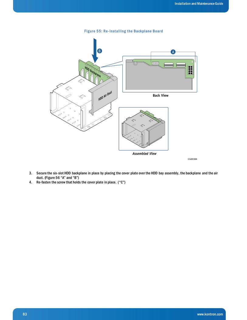
83 www.kontron.com
Installation and Maintenance Guide
F ig ur e 5 5 : Re - Inst al l ing t he Back plane Boar d
3. Secure the six-slot HDD backplane in place by placing the cover plate over the HDD bay assembly, the backplane and the air
duct. (Figure 56 “A” and “B”)
4. Re-fasten the screw that holds the cover plate in place. ( “C”)

84 www.kontron.com
Installation and Maintenance Guide
F ig ur e 5 6 : Re - At t aching t he Cov e r Plat e
5. Lock in all the hard drives so they engage with the backplane.
6. Re-attach the front panel bezel and the chassis cover. For instructions, see (RA) and (RL) in Chapter 6.
7. If this is the last task you are performing inside the server chassis, plug in the power cord(s), and re-attach any peripheral
devices.
6.4 (RC) Re-Installing the Cable Bundle Bracket and Fan Cage
The cable bundle bracket is under the support cross bar and just behind the fan cage. It is attached to the fan cage by two small
screws. Because both of these components need to be removed and are fastened together, they are treated as one assembly.
To re-install the cable bundle bracket and fan cage:
1. Fasten the fan cage (with the cable bracket attached) to the chassis floor using the two screws set aside when it was
removed.
85 www.kontron.com
Installation and Maintenance Guide
2. Reconnect all three power cables for the fan pairs on the fan control board. For instructions, see (RD) here in Chapter 6
3. Put the baseboard power cable bundles back onto the cable bundle bracket and re-connect the cables to the
baseboard. For instructions, see (RG) here in Chapter 6.
4. Place the three fan pairs that were set aside back into the fan cage.
6.5 (RD) Re-Connecting the Fan Control Cables
The fan control board has the following cables:
Fan Control Board PWR/SIG cable, which is part of the FP board multifunction connection that coordinates signals to »
the front panel
For the location of the FCB PWR/SIG connector (J1A1) on the FCB, see Figure 43 in Section 5.2.17.
Fan I2C cable, which connects the baseboard and the fan control board to provide fan control signals »
N O TE: This cable, also known as the IPMB cable, is covered in (RF) here in Chapter 6.
Fan Pair (Fans 1-2), Fan Pair (Fans 3-4), Fan Pair (Fans 5-6) cables, which each connect the FCB with a fan pair in the »
fan cage
For the location of the three fan pair connectors (J3A1, J6A1, J9A1) on the FCB, see Figure 43 in Section 5.2.17.
These cables are connected mechanically on the fan pairs in the fan cage.
Fan Control Board Power cable, which provides power from the PDB (soldered) to the FCB and the six fans »
For the location of the FCB power connector (J9A2) on the FCB, see Figure 43 in Section 5.2.17.
If any cables have to be reconnected at the other end, not just on the FCB, for the connector locations, see Figure 12, “Cable
Routing” and Table 1, “Cable Connections”.
6.6 (RE) Re-Connecting the HSBP Board Cables
The following cables all connect to the hot-swap backplane board at the back of the SAS HDD drive bay assembly:
SAS HDD Backplane board power cable that provides power from the PDB to the HSBP and up to six SAS HDDs »
For the location of the power connector (J11) on the HSBP, see Figure 55 in (RB) here in Chapter 6.
The other end of this cable is soldered onto the PDB.
SAS-1 (HDD 0-3) cable that connects the HSBP board to the SAS_0-3 connector on the baseboard or to an optional »
hardware RAID controller board
For the location of the SAS-1 connector (MINISAS0, J1) on the HSBP, see Figure 55 in (RB) here in Chapter 6.
For the location of the SAS_0-3 connector (J1H3) on the baseboard, see Figure 12: Cable Routing” in (E) in Chapter 4.
For the location of the SAS-1 connector on a hardware RAID controller card, see Figure 30 in Section 5.2.7 “Installing a
Hardware RAID Controller”.
SAS-2 (HDD 4-5) cable that connects the HSBP board to the SAS_4-7 connector on the baseboard or to an optional »
hardware RAID controller board
For the location of the SAS-2 connector (MINISAS1, J3) on the HSBP, see Figure 55 in (RB) here in Chapter 6.
For the location of the SAS_4-7 connector (J1H3) on the baseboard, see Figure 12: Cable Routing” in (E) in Chapter 4.
For the location of the SAS-1 connector on a hardware RAID controller card, see Figure 30 in Section 5.2.7 “Installing a
Hardware RAID Controller”.
Once you have reconnected the HSBP cables to the backplane board, you need to re-install the backplane board, replace the
cover plate, replace the HDD carriers in the drive bay, and re-attach the front bezel. For instructions, see (RB) and (RA) here in
Chapter 6.
6.7 (RF) Re-Connecting the Baseboard Signal Cables
Signal side cables connect to the baseboard on the left side. See Figure 12: Cable Routing” in (E) in Chapter 4.
86 www.kontron.com
Installation and Maintenance Guide
Baseboard to Front Panel Board Signal Cables
These cables all have a baseboard connection and a front panel board connection.
S S I Front Panel Board Cable
The SSI front panel board signal cable connects the front panel board connector (J1) with the baseboard (SSI_FRONT_PANEL,
J1A2).
For the location of the baseboard SSI front panel board connector, see Figure 12: Cable Routing” in (E) in Chapter 4.
For the location of the SSI power control signal connector on the FP board, see Figure 39 in Section 5.2.14.
S e rial Cable
The serial cable is part of the multifunction front panel board power and signal cable As part of the multifunction front pan el
board cable, along with the HDD LED cable and COM2, the serial cable interconnects the front panel board (FP board) with the
fan control board, the baseboard, and the HDD LEDs.
For the location of the multifunction cable connector on the FP board (J1A1), see Figure 39 in Section 5.2.14.
For the location of the serial connector on the baseboard (SERIAL_A), see Figure 12: Cable Routing” in (E) in Chapter 4.
F r ont Panel Board USB Cable
The front panel board USB cable connects the baseboard to the FP board to provide USB 2.0 signals.
For the location of the baseboard USB connector (USB-5-6, J1K1), see Figure 12: Cable Routing” in (E) in Chapter 4.
For the location of the USB connector on the FP board (J4), see Figure 39 in Section 5.2.14.
Other Baseboard Signal Cables
IPMB/Fan I2C Cable
The IPMB cable (aka Fan I2C) connects the baseboard with the fan control board (FCB) to provide fan control signals.
For the location of the IPMB connector (J1D4) on the baseboard, see Figure 12: Cable Routing” in (E) in Chapter 4.
For the location of the FCB I2C connector (J8A1), see Figure 43 in Section 5.2.17.
HS BP I2C Cable
The HSBP I2C cable connects the HDD HSBP (hot-swap backplane) to the baseboard and the front panel board to provide HDD
LED signal control on the disk drive carriers and on the system front panel.
For the location of the HSBP I2C connector (J2) on the HDD backplane, see Figure 55 here in (RB) Chapter 6.
For the location of the HSBP I2C/HDD LED connector (HDD-LED) on the FP board, see Figure 39 in Section5.2.14.
For the location of the HSBP I2C connector (J1D3) on the baseboard, see Figure 12: Cable Routing” in (E) in Chapter 4.
6.8 (RG) Re-Connecting the Baseboard Power Cables
The four baseboard power side cables all run from the power distribution board, across the cable bundle bracket in a protecti ve
cover, to their connectors on the baseboard.
Main Power
The baseboard SSI main power cable provides power to the baseboard and the power supply with the “PS-ON” signal from the
power distribution board. The cable is soldered to the PDB and connected to MAIN_PWR (J9G1).
For the location of the connector on the baseboard, see Figure 12: Cable Routing” in (E) in Chapter 4.
To reconnect the main power cable:
1. Run the cable bundle across the cable bundle bracket and connect it to the baseboard.
2. If present, re-cover with the black insulator covering.
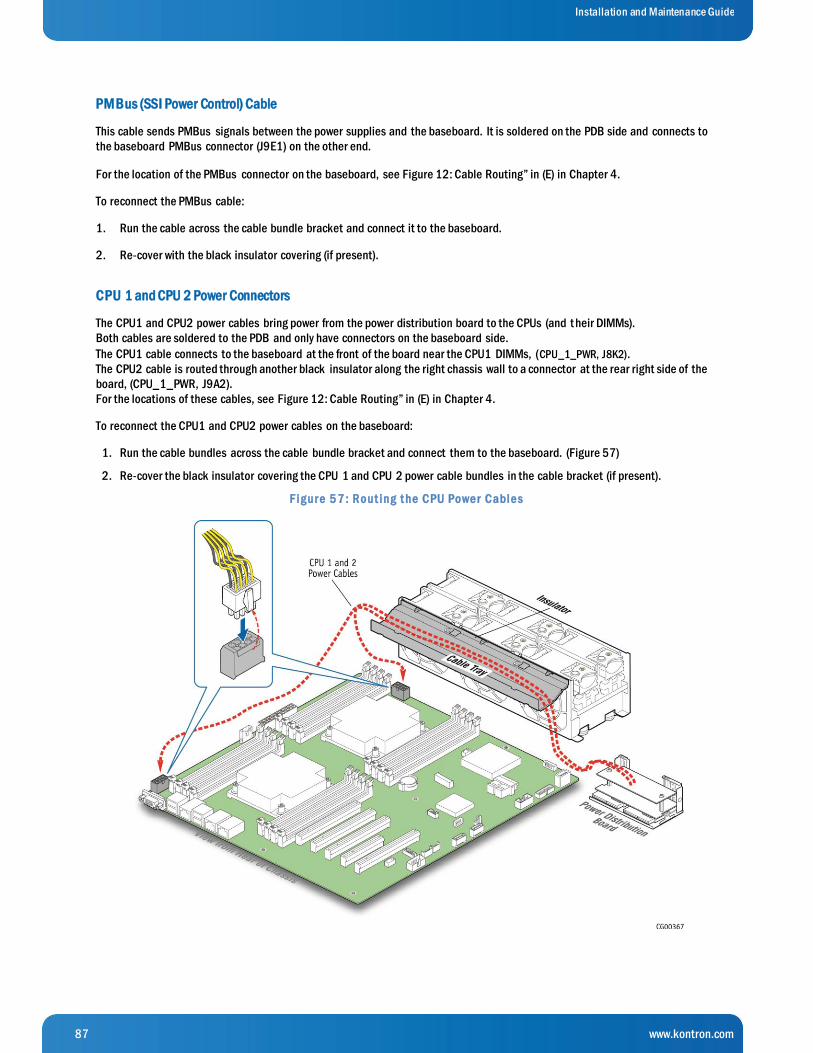
87 www.kontron.com
Installation and Maintenance Guide
PMBus (SSI Power Control) Cable
This cable sends PMBus signals between the power supplies and the baseboard. It is soldered on the PDB side and connects to
the baseboard PMBus connector (J9E1) on the other end.
For the location of the PMBus connector on the baseboard, see Figure 12: Cable Routing” in (E) in Chapter 4.
To reconnect the PMBus cable:
1. Run the cable across the cable bundle bracket and connect it to the baseboard.
2. Re-cover with the black insulator covering (if present).
CPU 1 and CPU 2 Power Connectors
The CPU1 and CPU2 power cables bring power from the power distribution board to the CPUs (and t heir DIMMs).
Both cables are soldered to the PDB and only have connectors on the baseboard side.
The CPU1 cable connects to the baseboard at the front of the board near the CPU1 DIMMs, (CPU_1_PWR, J8K2).
The CPU2 cable is routed through another black insulator along the right chassis wall to a connector at the rear right side of the
board, (CPU_1_PWR, J9A2).
For the locations of these cables, see Figure 12: Cable Routing” in (E) in Chapter 4.
To reconnect the CPU1 and CPU2 power cables on the baseboard:
1. Run the cable bundles across the cable bundle bracket and connect them to the baseboard. (Figure 57)
2. Re-cover the black insulator covering the CPU 1 and CPU 2 power cable bundles in the cable bracket (if present).
F ig ur e 5 7 : Rout ing t he CPU Powe r Cable s
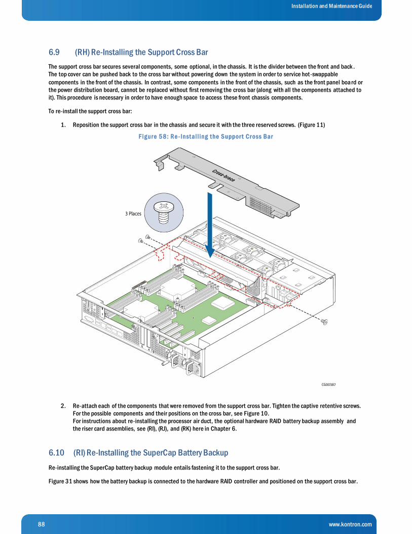
88 www.kontron.com
Installation and Maintenance Guide
6.9 (RH) Re-Installing the Support Cross Bar
The support cross bar secures several components, some optional, in the chassis. It is the divider between the front and back .
The top cover can be pushed back to the cross bar without powering down the system in order to service hot-swappable
components in the front of the chassis. In contrast, some components in the front of the chassis, such as the front panel boa rd or
the power distribution board, cannot be replaced without first removing the cross bar (along with all the components attached to
it). This procedure is necessary in order to have enough space to access these front chassis components.
To re-install the support cross bar:
1. Reposition the support cross bar in the chassis and secure it with the three reserved screws. (Figure 11)
F ig ur e 5 8 : Re - Inst al l ing t he S uppor t Cr oss Bar
2. Re-attach each of the components that were removed from the support cross bar. Tighten the captive retentive screws.
For the possible components and their positions on the cross bar, see Figure 10.
For instructions about re-installing the processor air duct, the optional hardware RAID battery backup assembly and
the riser card assemblies, see (RI), (RJ), and (RK) here in Chapter 6.
6.10 (RI) Re-Installing the SuperCap Battery Backup
Re-installing the SuperCap battery backup module entails fastening it to the support cross bar.
Figure 31 shows how the battery backup is connected to the hardware RAID controller and positioned on the support cross bar.
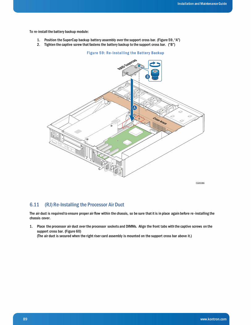
89 www.kontron.com
Installation and Maintenance Guide
To re-install the battery backup module:
1. Position the SuperCap backup battery assembly over the support cross bar. (Figure 59, “A”)
2. Tighten the captive screw that fastens the battery backup to the support cross bar. (“B”)
F ig ur e 5 9 : Re - Inst al l ing t he Bat t e r y Back up
6.11 (RJ) Re-Installing the Processor Air Duct
The air duct is required to ensure proper air flow within the chassis, so be sure that it is in place again before re -installing the
chassis cover.
1. Place the processor air duct over the processor sockets and DIMMs. Align the front tabs with the captive screws on the
support cross bar. (Figure 60)
(The air duct is secured when the right riser card assembly is mounted on the support cross bar above it.)

90 www.kontron.com
Installation and Maintenance Guide
F ig ur e 6 0 : Re - Inst al l ing t he Pr oce ssor Air Duct
6.12 (RK) Re-Installing a Riser Card Assembly
This procedure covers both the right and left riser card assemblies.
6.12.1 Re-Installing the Left Riser Card Assembly
To re-install the riser card assembly:
1. Position the riser front tabs over the holes on the PCI support cross bar. (Figure 61).
2. Using the blue touch points on the top of the assembly (“A”), press down to mate the riser card with the header on the
server board (“B”, slot 2 for the left-side riser)

91 www.kontron.com
Installation and Maintenance Guide
F ig ur e 6 1 : Re - Inst al l ing t he Le ft Rise r Car d Asse mbly
N O TES: 1) To avoid damaging the card edge, be sure that the card is lined up straight with the header, not on an angle.
2) If a hardware RAID controller card is installed in PCI slot 3, be careful not to damage the diagnostic pins at the
back of the card next to the rear chassis panel when re-installing the left-side riser assembly.
3. Align and then tighten the blue captive retention screws at the front of the assembly with the holes on the support cross
bar (“C”) and on the rear of the chassis. (“D”.
4. Replace the chassis cover. For instructions see (RL) here in Chapter 6.
6.12.2 Re-Installing the Right Riser Card Assembly
To re-install the riser card assembly:
1. Position the riser front tabs over the holes on the PCI support cross bar (over the processor air duct). (Figure 62).
2. Using the blue touch points on the top of the assembly (“A”), press down to mate the riser card with the header on the
server board (“B”, slot 6 for the right-side riser)

92 www.kontron.com
Installation and Maintenance Guide
F ig ur e 6 2 : Re - Inst al l ing t he Rig ht Rise r Car d Asse mbly
N O TE: To avoid damaging the card edge, be sure that the card is lined up straight with the header, not on an angle.
3. Align and then tighten the blue captive retention screws at the front of the assembly with the holes on the support cross
bar (“C”) and on the rear of the chassis. (“D”.
4. Replace the chassis cover. For instructions see (RL) here in Chapter 6.
6.13 (RL) Re-installing the Chassis Cover
When you are finished working inside the chassis, always put the cover back on before powering on the server again. This step is
required to ensure proper cooling.
1. Starting from the rear of the chassis, align the tab on the rear right edge of the cover with the lock bracket on the
outside of the rear panel and place the cover down over the chassis with the side edges outside the chassis walls.
(Figure 63, “A”)
CAUTION: When re-installing the cover, make sure that the guide pin and the notch are aligned (“B”) and do not
apply excessive force when sliding the cover in place. Misalignment or excessive force may cause damage to the
cover’s guide pin.
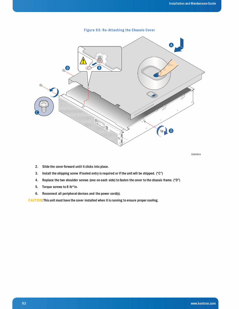
93 www.kontron.com
Installation and Maintenance Guide
F ig ur e 6 3 : Re - At t aching t he Chassis Cov e r
2. Slide the cover forward until it clicks into place.
3. Install the shipping screw if tooled entry is required or if the unit will be shipped. (“C”)
4. Replace the two shoulder screws (one on each side) to fasten the cover to the chassis frame. (“D”)
5. Torque screws to 8 lb*in.
6. Reconnect all peripheral devices and the power cord(s).
CAUTION: This unit must have the cover installed when it is running to ensure proper cooling.
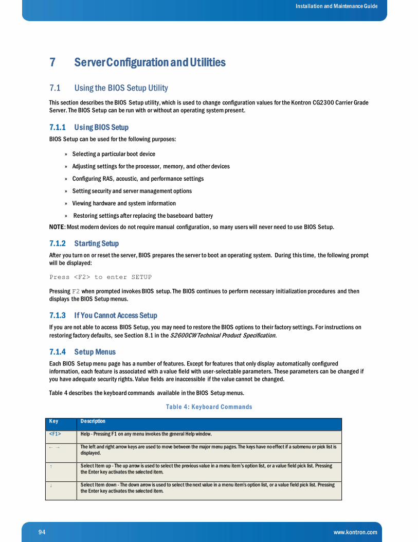
94 www.kontron.com
Installation and Maintenance Guide
7 Server Configuration and Utilities
7.1 Using the BIOS Setup Utility
This section describes the BIOS Setup utility, which is used to change configuration values for the Kontron CG2300 Carrier Grade
Server. The BIOS Setup can be run with or without an operating system present.
7.1.1 Using BIOS Setup
BIOS Setup can be used for the following purposes:
Selecting a particular boot device »
Adjusting settings for the processor, memory, and other devices »
Configuring RAS, acoustic, and performance settings »
Setting security and server management options »
Viewing hardware and system information »
Restoring settings after replacing the baseboard battery »
NOTE: Most modern devices do not require manual configuration, so many users will never need to use BIOS Setup.
7.1.2 Starting Setup
After you turn on or reset the server, BIOS prepares the server to boot an operating system. During this time, the following prompt
will be displayed:
Press <F2> to enter SETUP
Pressing F2 when prompted invokes BIOS setup. The BIOS continues to perform necessary initialization procedures and then
displays the BIOS Setup menus.
7.1.3 If You Cannot Access Setup
If you are not able to access BIOS Setup, you may need to restore the BIOS options to their factory settings. For instructions on
restoring factory defaults, see Section 8.1 in the S2600CW Technical Product Specification.
7.1.4 Setup Menus
Each BIOS Setup menu page has a number of features. Except for features that only display automatically configured
information, each feature is associated with a value field with user-selectable parameters. These parameters can be changed if
you have adequate security rights. Value fields are inaccessible if the value cannot be changed.
Table 4 describes the keyboard commands available in the BIOS Setup menus.
Table 4 : K e y boar d Commands
K e y De scription
<F1> Help - Pressing F1 on any menu invokes the general Help window.
← → The left and right arrow keys are used to move between the major menu pages. The keys have no effect if a submenu or pick list is displayed.
↑ Select Item up - The up arrow is used to select the previous value in a menu item’s option list, or a value field pick list. Pressing the Enter key activates the selected item.
↓ Select Item down - The down arrow is used to select the next value in a menu item’s option list, or a value field pick list. Pressing the Enter key activates the selected item.

95 www.kontron.com
Installation and Maintenance Guide
K e y De scription
F5/- Change Value - The minus key or the F5 function key is used to change the value of the current item to the previous value. This key
scrolls through the values in the associated pick list without displaying the full list.
F6/+ Change Value - The plus key or the F6 function key is used to change the value of the current menu item to the next value. This key scrolls through the values in the associated pick list without displaying the full list. On 106-key Japanese keyboards, the plus key has a different scan code than the plus key on the other keyboard, but it has the same effect.
<Enter> Execute Command - The Enter key is used to activate submenus when the selected feature is a submenu, or to display a pick list if a selected feature has a value field, or to select a sub-field for multi-valued features like time and date. If a pick list is displayed, the Enter key undoes the pick list and allows another selection in the parent menu.
<Esc> Exit - The ESC key provides a mechanism for backing out of any field. This key undoes pressing the Enter key. When the ESC key is pressed while editing a field or selecting menu features, the parent menu is re-entered. When the ESC key is pressed in any submenu, the parent menu is re-entered. When the ESC key is pressed in any major menu, the exit confirmation window is displayed and the user is asked whether changes can be discarded.
<F9> Setup Defaults - Pressing F9 causes the following message to appear:
Setup Confirmation
Load default configuration now?
[Yes] [No]
If Yes is selected and the Enter key is pressed, all Setup fields are set to their default values. If No is selected and the Enter key
is pressed, or if the ESC key is pressed, the screen returns to where it was before F9 was pressed without affecting any existing field values.
<F10> Save and Exit - Pressing F10 causes the following message to appear:
Setup Confirmation
Save Configuration changes and exit now?
[Yes] [No]
If Yes is selected and the Enter key is pressed, all changes are saved and Setup is exited. If No is selected and the Enter key is
pressed, or the ESC key is pressed, the screen returns to where it was before F10 was pressed without affecting any existing values.
7.2 Single PSU or CPU System - Configuring Sensor Data Repository (SDR)
At factory, CG2300 unit is programmed with two CPUs and two PSUs. This means that the IPMI SDR (Sensor Data Repository) is
populated so the system expects two PSUs and two CPUs. Follow the steps below (section 7.2.2) if your system if configured
differently in terms of PSU and/or CPU number.
NOTE: DIMM configuration does not require SDR reprogrammation.
7.2.1 Two (2) Power Supplies + Two (2) Processors Configuration
If the final configuration has two PSUs and two CPUs, factory SDR is ready to use and nothing has to be done on this regard,
unless there is a more recent SDR version available. Go to section 7.3 “Upgrading the System Firmware” if you would like to
upgrade the SDR version.
7.2.2 Non-Redundant Power Unit and/or Single Processor Configuration
If the final system configuration has only one PSU (non-redundant config) and/or CPU (single CPU config), you must reconfigure
the system’s SDR.
WARNING: System will not be fully healthy if the SDR is not reconfigured, returning some unhealthy indications such as:

96 www.kontron.com
Installation and Maintenance Guide
- System Fans will stay at max speed at all time;
- Front panel LED will indicate alarms (System Status LED, Alarms LEDs);
- System Event Log will trig some unhealthy events.
This is due to missing components (CPU and/or PSU) that are expected from the factory “default”.
To update your SDR, assemble your system at its final configuration (install CPU, DIMMs and PSU), then follow Upgrade
Procedure given at section 7.3.1 below, reconfiguring only the SDR by invoking updFRUSDR.nsh script at step 7.
When updating SDR, user must answer a few questions as what are the preferences for:
- Component to update: FRU, SDR or both
o Choose SDR only - BMC Telco Alarm Manager: Activated or Deactivated – Factory Default is Activated
o Your preference – suggest same as Factory Default unless otherwise instructed - Color LED preference if TAM is Activated – Factory Default is “3 – Default LED Color - All Severities”
o Your preference – suggest same as Factory Default unless otherwise instructed
Finally, you must disable SDR AutoConfig (not used in the CG2300), by sending two IPMI commands to the BMC:
- ipmitool raw 0x3e 0x73 0x3
- ipmitool mc reset cold
7.3 Upgrading the System Firmware
Please refer to www.kontron.com to download the latest FW versions available for the CG2300.
- Newer versions of FW components were possibly released between the manufacturing process of the chassis and the
moment your system got delivered to you.
- You may have been informed by Kontron that your running system would benefit to get the latest FW upgrades.
Consider using new FW loads to optimize your CG2300 ’s functionality.
Below is the upgrade procedure to follow to perform such upgrade.
7.3.1 Upgrade Procedure for FW components
WARNING: Do not power off or reset the system while the update is in progress. Do not interrupt the BIOS POST during the first
system reboot.
To update the CG2300 server firmware, follow the standard update procedure in the embedded EFI shell.
N O TE: Components (e.g., BIOS, BMC, ME, SDR) can be updated individually as shown below, but upgrading the full package is
recommended to avoid possibly running incompatible firmware components.
The update package is available at www.kontron.com/ (search for CG2300, click on DOWNLOAD: CG2300 Software Update
Package)
1. Uncompress the update package and copy the contents to a USB flash drive.
2. Insert the USB flash drive into any of the USB ports on the system.
3. Power up the system and boot the EFI shell. (Press F6 and select “EFI”)
4. Run the command “map-r” in the EFI shell to mount the USB flash drive.
5. Run the command “fs0” to change the active device to the USB flash drive.
The USB key can also be mounted to “fs1”. The fs# depends on the results from the “map-r” command.
6. Change the directory to the folder that stores the firmware package. (e.g., cd NewFW-CG2300)
7. Type in “updALL.nsh” at the shell prompt to initiate updating the BIOS and all firmware. (See steps below for
updating single components instead.)
8. When prompted for the FRUSDR update, select the either the option to update only the SDR or the option to update
both the FRU and SDR.
9. Answer the rest of the FRUSDR prompts as you want.
97 www.kontron.com
Installation and Maintenance Guide
10. Provide input to the additional prompts. (Updating each specific FRU area is optional; “Yes” or “No”)
11. When the FRU update is complete, the system returns to the EFI shell prompt.
Type “Reset” to reset the system.
The system takes three minutes or so to reboot so it can actually update the firmware. Do not interfere with this
process.
12. During POST, press <F2> to enter the BIOS setup.
13. In the BIOS Setup screens, verify that the BIOS, ME, BMC, and FRUSDR revisions were loaded.
14. Press <F10> and answer “Yes” to load the BIOS setup defaults.
15. Configure the BIOS settings you want.
16. Save the settings and reboot the system.
To update single components (e.g., BIOS, BMC, ME, SDR), instead of “updALL.nsh”, at step 7 in the procedure above, use
the appropriate script, corresponding to the component to update:
BIOS: updBIOS.nsh
BMC: updBMC.nsh
ME: updME.nsh
NOTE: In the unlikely event that a BIOS error occurs during the BIOS update process, a recovery process may need to be followed
to return the system to service. See Section 1.4, “Additional Information and Software” for additional information.
7.4 BIOS Default and Password Reset Usage Procedure
The BIOS Default and Password Reset recovery features are designed so the desired operation can be achieved with minimal
system downtime. The usage procedure for these two features has changed from previous generation Intel® Server Boards. The
following procedure outlines the new usage model.
The server boards have several 3-pin jumper blocks that can be used to configure, protect, or recover specific features of the
server boards.
7.4.1 Set BIOS to Default (Clearing the CMOS)
To clear the CMOS, perform the following steps:
1. Power down the server. Unplug the power cord.
2. Open the server chassis. For instructions, see (A) in Chapter 4.
3. Move the jumper from the default operating position (covering pins 1 and 2) to the reset/clear position (covering pins 2 and
3).
4. Wait five seconds.
5. Move the jumper back to the default position (covering pins 1 and 2).
6. Close the server chassis. For instructions, see (RL) in Chapter 6.
7. Connect the AC power cord.
8. Power up the server and access the BIOS setup utility by pressing <F2>.
9. Verify that the BIOS default operation was successful by viewing the Error Manager screen.
Two errors should be logged:
5220 BIOS Settings reset to default settings
0012 System RTC date/time not set
98 www.kontron.com
Installation and Maintenance Guide
The CMOS is now cleared and can be reset by going into the BIOS setup.
N O TE: This jumper does not reset Administrator or User passwords. To reset passwords, the Password Clear jumper must be used.
The system will automatically power on after AC is applied.
7.4.2 Clearing the Password
This jumper causes both the User password and the Administrator password to be cleared if they were set. The operator should be
aware that this creates a security gap until passwords have been installed again through the <F2> BIOS Setup utility. This is the
only method by which the Administrator and User passwords can be cleared unconditionally. Other than this jumper, passwords
can only be set or cleared by changing them explicitly in BIOS Setup or by similar means. No method of resetting BIOS
configuration settings to default values will affect either the Administrator or User passwords.
To clear the password, perform the following steps:
1. Power down the server. For safety, unplug the power cord(s).
2. Remove the system top cover.
3. Move the “Password Clear” jumper from the default operating position (covering pins 1 and 2) to the password clear
position (covering pins 2 and 3).
4. Re-attach the system top cover and plug in the power cord(s).
5. Power up the server and access the <F2> BIOS Setup utility.
6. Verify the password clear operation was successful by viewing the Error Manager screen.
7. Two errors should be logged:
5221 Passwords cleared by jumper
5224 Password clear jumper is set
8. Exit the BIOS Setup utility and power down the server. For safety, unplug the AC power cords.
9. Remove the system top cover and move the “Password Clear” jumper back to the default operating position (covering pins 1
and 2).
10. Re-attach the system top cover and plug in the AC power cord(s).
11. Power up the server.
12. The password is now cleared and can be reset by going into the BIOS setup.
7.5 Integrated BMC Force Update Procedure
When performing the standard Integrated BMC firmware update procedure, the update utility places the Integrated BMC into an
update mode, allowing the firmware to load safely onto the flash device. In the unlikely event the Integrated BMC firmware
update process fails due to the Integrated BMC not being in the proper update state, the server board provides an Integrated
BMC Force Update jumper that forces the Integrated BMC into the proper update state.
The following procedure should be completed in the event the standard Integrated BMC firmware update process fails.
1. Power down and remove the AC power cord.
2. Open the server chassis. For instructions, see (A) in Chapter 6.
3. Move the jumper from the default operating position (covering pins 1 and 2) to the enabled position (covering pins 2 and 3).
4. Close the server chassis.
5. Reconnect the AC cord and power up the server.
6. Perform the Integrated BMC firmware update procedure as documented in the README.TXT file that is included in the
Integrated BMC firmware update package.
After successful completion of the firmware update process, the firmware update utility may generate an error stating that the
Integrated BMC is still in update mode.
7. Power down and unplug the AC power cord(s).
99 www.kontron.com
Installation and Maintenance Guide
8. Open the server chassis.
9. Move the jumper from the enabled position (covering pins 2 and 3) to the disabled position (covering pins 1 and 2).
10. Close the server chassis.
11. Re-connect the AC cord(s) and power up the server.
N O TE: Normal Integrated BMC functionality is disabled with the Force Integrated BMC Update jumper set to the enabled position.
The server should never be run with the Integrated BMC Force Update jumper set in this position. This jumper setting should only
be used when the standard firmware update process fails. This jumper should remain in the default/disabled position when the
server is running normally.
7.6 ME Force Update Jumper
When the ME Firmware Force Update jumper is moved from its default position, the ME is forced to operate in a reduced minimal
operating capacity. This jumper should only be used if the ME firmware has become corrupted and requires re-installation.
The following procedure should be followed.
1. Power down and remove the AC power cord(s).
2. Open the server chassis. For instructions, see (A) in Chapter 6.
3. Move the jumper from the default operating position (covering pins 1 and 2) to the enabled position (covering pins 2 and 3).
4. Close the server chassis.
5. Re-connect the AC cord(s) and power up the server.
6. Boot to the EFI shell and update the ME firmware using the “MEComplete.cap” file with the following command:
iflash32 /u /ni MEComplete.cap
7. Power down and unplug the AC power cord(s).
8. Open the server chassis.
9. Move the jumper from the enabled position (covering pins 2 and 3) to the disabled position (covering pins 1 and 2).
10. Close the server chassis.
11. Reconnect the AC cord(s) and power up the server.
7.7 BIOS Recovery Jumper
When the BIOS Recovery jumper block is moved from its default pin position (pins 1-2), the system will boot to the uEFI shell,
where a standard BIOS update can be performed. See the BIOS update instructions that are included with System Update
Packages (SUP) downloaded from Intel’s download center web site. This jumper is used when the system BIOS has become
corrupted and is non-functional, requiring a new BIOS image to be loaded on to the server board.
The following procedure should be followed:
1. Turn off the system.
2. For safety, remove the AC power cord(s).
3. Remove the system top cover.

100 www.kontron.com
Installation and Maintenance Guide
4. Move the “BIOS Recovery” jumper from the default operating position (covering pins 1 and 2) to the BIOS Recovery position
(covering pins 2 and 3).
5. Reinstall the system top cover and reattach the AC power cord(s).
6. Power up the system.
7. The system will automatically boot to the EFI shell. Update the BIOS using the standard BIOS update instructions provided with
the system update package.
8. After the BIOS update has successfully completed, power off the system. For safety, unplug the AC power cord(s) from the
system.
9. Remove the system top cover.
10. Move the “BIOS Recovery” jumper back to the default operating position (covering pins 1 and 2).
11. Re-attach the system top cover and plug in the AC power cord(s).
12. Power up the system and access the <F2> BIOS Setup utility.
13. Configure the desired BIOS settings.
14. Press the <F10> key to save and exit the utility.
7.8 Restoring BIOS Default Settings
If you are not able to access the BIOS setup screens, you may need to restore the BIOS settings to their factory defaults by
clearing the CMOS. This procedure requires physical access to the inside of the server.
1. Power down the system but do not disconnect the power cord(s).
2. Open the server. See (A) in Chapter 4 for instructions.
3. Remove the right-side, slot 5 riser assembly. For instructions, see “(B) Removing a Riser Card Assembly”.
4. Remove the processor air duct. For instructions, see “(C) Removing the Processor Air Duct”.
5. Locate the “BIOS Default” jumper (J2J2) as shown in Figure 29.
6. Move jumper (J2J2) from the normal position covering pins 1-2 to the reset/clear position covering pins 2-3.
7. Wait five seconds and remove power.
8. Move the jumper (J2J2) back to the normal default position (pins 1-2).
9. Re-install the processor air duct and the right-side riser card assembly.
10. Close the server chassis. See (RL) in Chapter 6 for instructions.
11. Power up the server.
The CMOS is now cleared and can be reset by going into the BIOS setup.
N O TE: Removing power before performing the CMOS clear operation causes the system to automatically power up and
immediately power down after the procedure is followed and power is re-applied. If this happens, remove the power cord again,
wait 30 seconds, and reconnect the power cord. Then, power up the system and proceed to the <F2> BIOS Setup utility to reset
the settings.

101 www.kontron.com
Installation and Maintenance Guide
8 Troubleshooting
This chapter assists with identifying and solving problems that might occur while using the Kontron CG2300 Carrier Grade Server.
For any issue, first ensure you are using the latest firmware and files. Firmware upgrades include updates for BIOS and the
baseboard management controller (BMC). Go to http://www.kontron.com/products/systems/telecom-systems/cg2300-
carrier-grade-rackmount-server.html , click on downloads, BIOS for information about the latest updates. In addition to the
server firmware and files, also update any drivers used for components installed in the system, such as video drivers, network
drivers, and SAS drivers.
If these steps do not help resolve the server problems, see Appendix D: Getting Help” for assistance.
8.1 CPU Socket Inspection
The following socket pin inspection procedure, which is used by Kontron contract manufacturers, was developed by Kontron
manufacturing engineers, based on CPU socket designer guidelines. Kontron recommends that all users perform a socket
inspection before adding or replacing a CPU in the CG2300 server. These inspection steps may also be helpful for other
debugging purposes as well.
N O TE: There are two levels of inspection in this procedure and three different criteria for rejecting a socket. Before returning the
CG2300 system to Kontron for RMA based on bent pins, be sure the socket you are examining meets the two-level rejection
criteria in these instructions.
8.1.1 First Level Inspection
Visually inspect the socket contact array as follows:
1. Hold the socket load plate open and get within 6 to 12 inches of the socket on the server board.
2. Using a magnification task light, scan the socket contacts while tilting the light away from the socket 15 to 45 degrees and
rotating your gaze 15 to 45 degrees from perpendicular to change your viewing angle three times.
Rejection Criteria
If the socket fails one of the following criteria, go on to the second level inspection before concluding there a re bent pins.
Any contact that does not reflect light back at all while the rest of the contacts around it do »
Any contact that reflects light earlier or later than the rest »
Any foreign material in sufficient quantities to be detectable with un-aided vision »
8.1.2 Second Level Inspection
If an alignment problem is found, confirm the defect under a microscope.
1. A contact is bent backwards upon itself or has shifted up or down from the normal position
Re jection Criteria
Contact tips do not lie within +/- one contact thickness from the plane defined by call contact tips as shown in Figure »
64.

102 www.kontron.com
Installation and Maintenance Guide
F ig ur e 6 4 : Be nt Pin Ex ample
A contact is shifted sideways 2.
Re jection Criteria
Contact tips are not aligned within +/- 1 contact width of the suspect contact tip as shown in Figure Figure 65. »
F ig ur e 6 5 : Cont act S hift e d S ide way s Ex ample
N O TE: Red circles indicate failed contacts.
If the socket fails criteria in both inspection levels, it is defective. Possible actions are:
Return the server board directly to Intel (high volume system integrators) »
or
RMA the whole CG2300 server to Kontron (low volume users) »
Contact Technical Support to get an RMA number and specify that the issue was found in Section 8.1, “CPU Socket
Inspection” in the CG2300 Server Installation and Maintenance Guide.
8.2 Resetting the System
Before going through in-depth troubleshooting, first attempt to reset the system using one of these methods:
T o do this: Press:
Soft boot reset to clear the system memory and reload the operating system <Ctrl+Alt+Del>
Clear system memory, restart POST, and reload the operating system Reset button
Cold boot reset. Turn the system power off and then on. This clears system memory,
restarts POST, reloads the operating system, and halts power to all peripherals
Power on/off
8.3 Problems Following Initial System Installation
Problems that occur at initial system startup are usually caused by an incorrect installation or configuration. Hardware fail ure is a
less frequent cause. If the problem you are experiencing is with a specific software application, see “Problems with Newly
Installed Application Software”.
103 www.kontron.com
Installation and Maintenance Guide
8.3.1 First Steps Checklist
Is power available at the source? »
Are the power supplies plugged in? Check the power cable on the back of the server and at the power source. »
Is the system power cord properly connected to the system? For AC-powered systems, is the power cord plugged into a »
NEMA (National Electrical Manufacturing Association) 5-15R outlet for 100-120V or a NEMA 6-15R outlet for 200-
240V
Are all cables correctly connected and secured? »
Are the processors fully seated in their sockets on the server board? »
Are all standoffs in the proper location and not touching any components, causing a potential short? »
Are all PCI Express* (PCIe*) add-in cards fully seated in their slots in the respective riser cards? »
Are all jumper settings on the server board correct? »
Are all jumper and switch settings on add-in boards and peripheral devices correct? »
To check these settings, refer to the manufacturer's documentation that comes with them. If applicable, ensure that »
there are no conflicts-for example, two add-in boards sharing the same interrupt.
Are all peripheral devices installed correctly? »
Are the hard disk drives (up to 6) properly formatted or configured? »
Are all device drivers properly installed? »
Are the configuration settings made in Setup correct? »
Is the operating system properly loaded? Refer to the operating system documentation. »
Was the system power on/off switch on the front panel pressed to turn the server on (power on light should be lit)? »
Are all integrated components from the tested components lists? Check the tested memory list and the supported »
hardware and operating system list. Go to http://www.kontron.com/products/systems/telecom-systems/cg2300-
carrier-grade-rackmount-server.html for links to the tested component lists.
8.4 Hardware Diagnostic Testing
This section provides a more detailed approach to identifying a hardware problem and locating its source.
CAUTION: Turn off devices before disconnecting cables.
Before disconnecting any peripheral cables from the system, turn off the system and any external peripheral devices. Failure to
do so can cause permanent damage to the system and/or the peripheral devices.
1. Turn off the system and all external peripheral devices. Disconnect each of devices from the system, except for the keyboard
and the video monitor.
2. Make sure the system power cord is plugged into a properly grounded AC outlet .
3. Make sure the video display monitor and keyboard are correctly connected to the system. Turn on the video monitor. Set its
brightness and contrast controls to at least two thirds of their maximum ranges. (See the documentation supplied with the
video display monitor).
4. Turn on the system. If the power LED does not light, see Section 7.4.1, “Power Light does not Light”.
8.4.1 Verifying Proper Operation of Key System Lights
As POST determines the system configuration, it tests for the presence of each mass storage device installed in the system. As
each device is checked, its activity light should turn on briefly. Check for the following:

104 www.kontron.com
Installation and Maintenance Guide
If system LEDs are illuminated, see Section 7.5, “LED Information” for a description of the LED lights and steps that »
need to be taken to correct the problem.
8.4.2 Confirming the Operating System Load
Once the system boots up, the operating system prompt appears on the screen. The prompt varies according to the operating
system. If the operating system prompt does not appear, see “No Characters Appear on Screen”.
8.5 Specific Problems and Corrective Actions
This section provides possible solutions for specific problems:
Try the solutions below in the order given. If the problem cannot be corrected, contact your service representative or authorized
dealer for help. See “Appendix D: Getting Help” for contact details.
8.5.1 Power Light does not Light
Check the following:
Was the power-on button pressed? »
Is the system operating normally? If so, the power LED might be defective or the cable from the front panel to the server »
board might be loose.
Is the server power cord securely plugged into the power supply? »
For AC, will other items plugged into the same power outlet function correctly? »
Remove all add-in cards and see if the system boots. If successful, re-insert the cards one at a time with a reboot »
between each addition.
Make sure the memory DIMMs comply with the system requirements. »
Make sure the memory DIMMs have been populated according to the system requirements. »
Remove the memory DIMMs and re-seat them. »
Make sure the processor complies with the system requirements. »
Remove the processor and re-seat it. »
8.5.2 No Characters Appear on Screen
Check the following:
Is the keyboard functioning? Test it by turning the “Num Lock” function on and off to make sure the Num Lock light is »
functioning.
Is the video monitor plugged in and turned on? If you are using a switch box, is it switched to the correct system? »
Are the brightness and contrast controls on the video monitor properly adjusted? »
Is the video monitor signal cable properly installed? »
Does this video monitor work correctly if plugged into a different system? »
Is the onboard video controller enabled in the BIOS? »
Remove all add-in cards and see if the video returns. If successful, re-insert the cards one at a time with a reboot »
between each addition.
Make sure the memory DIMMs comply with the system requirements. »
Make sure the memory DIMMs have been populated according to the system requirements. »

105 www.kontron.com
Installation and Maintenance Guide
Remove the memory DIMMs and re-seat them. »
Make sure the processor complies with the system requirements. »
Remove the processor and re-seat it. »
8.5.3 Characters are Distorted or Incorrect
Check the following:
Are the brightness and contrast controls properly adjusted on the video monitor? »
See the manufacturer’s documentation.
Are the video monitor’s signal and power cables properly installed? »
Does this video monitor work correctly if plugged into a different system? »
8.5.4 System Cooling Fans do not Rotate Properly
If the system cooling fans are not operating properly, it is an indication of possible system component failure.
Check the following:
Is the power-on light lit? If not, see Section 7.4.1, “Power Light does not Light”. »
Are any other front panel LEDs lit? »
Have any of the fan motors stopped? Use the server management subsystem to check the fan status. »
Have the fans sped up in response to an overheating situation? »
Have the fans sped up in response to a fan that has failed? »
Are the fan power connectors properly connected to the front panel (FP) board? »
Is the cable from the front panel board connected to the both the front panel board and to the server board? »
Are the power supply cables properly connected to the FP board? »
Are there any shorted wires caused by pinched-cables or have power connector plugs been forced into power connector »
sockets the wrong way?
8.5.5 Cannot Connect to a Server
Make sure the network cable is securely attached to the correct connector at the system back panel. »
Try a different network cable. »
Make sure the correct and the current drivers are being used. Go to »
http://www.kontron.com/products/systems/telecom-systems/cg2300-carrier-grade-rackmount-server.html for a link
to the drivers.
Make sure the driver is loaded and the protocols are bound. »
Make sure the hub port is configured for the same duplex mode as the network controller. »
Make sure the correct networking software is installed. »
If you are directly connecting two servers (without a hub), you will need a crossover cable.
8.5.6 Diagnostics Pass but the Connection Fails
Make sure the network cable is securely attached. »
106 www.kontron.com
Installation and Maintenance Guide
Make sure to specify the correct frame type in the NET.CFG file. »
8.5.7 The (NIC) Controller Stopped Working When an Add-in Adapter was Installed
Make sure the cable is connected to the port from the onboard network controller. »
Make sure the BIOS is current. Go to http://www.kontron.com/products/systems/telecom- systems/cg2300-carrier-»
grade-rackmount-server.html for a link to the current version.
Try reseating the add-in adapter. »
8.5.8 The Add-in Adapter Stopped Working without Apparent Cause
Try reseating the adapter first; then try a different slot if necessary. »
The network driver files may be corrupt or deleted. Delete and then reinstall the drivers. »
Run the diagnostics. »
8.5.9 System Boots When Installing a PCI Card
System Server Management features require full-time “standby” power. This means some parts of the system have power going
to them whenever the power cord is plugged in, even if the system power is turned off with the power button on the front panel. If
you install a PCI card with the power cord plugged in, a signal may be sent to command the system to boot. Before installing a
PCI card, always:
1. Turn off the server power by using the power button on the front of the system.
2. Unplug the power cord(s) from the server.
8.5.10 Problems with Newly Installed Application Software
Problems that occur when you run new application software are usually related to the software, not the server hardware. Faulty
equipment is unlikely, especially if other software runs correctly.
Check the following:
Make sure the system meets the minimum hardware requirements for the software. See the soft ware documentation. »
Make sure the software is properly installed and configured for the system. See the software documentation. »
Use only an authorized copy. Unauthorized copies often do not work. »
Make sure the correct device drivers installed. »
If the problems persist, contact the software vendor’s customer service representative.
8.5.11 Problems with Application Software that Ran Correctly Earlier
Problems that occur after the system hardware and software have been running correctly sometimes indicate equipment failure.
However, they can also be caused by file corruption or changes to the software configuration.
Check the following:
Uninstall and reinstall the software. Make sure all necessary files are installed. »
If the problems are intermittent, there may be a loose cable, dirt in the keyboard (if keyboard input is incorrect), a »
marginal power supply, or other random component failures.

107 www.kontron.com
Installation and Maintenance Guide
If you suspect that a transient voltage spike, power outage, or brownout might have occurred, reload the software and »
try running it again. Symptoms of voltage spikes include a flickering video display, unexpected system reboots, and the
system not responding to user commands.
NOTE: For AC power, if you are getting random errors in data files, they may be getting corrupted by voltage spikes on the power
line. If you are experiencing any of the above symptoms that might indicate voltage spikes on the power line, it may help to install
a surge suppressor between the power outlet and the system power cord.
8.5.12 Devices are not Recognized under Device Manager (Windows*OS)
The Windows* operating systems do not include all of the drivers for the Intel® chipsets, onboard NICs, and other components.
Check the Kontron Deployment CD that came with the server or go to http://www.kontron.com/products/systems/telecom-
systems/cg2300-carrier-grade-rackmount-server.html for a link to the current drivers and chipset files.
8.5.13 Hard Drive(s) are not Recognized
Check the following:
Make sure the drive is not disabled in BIOS Setup. »
Make sure the drive is compatible. Go to http://www.kontron.com/products/systems/telecom-systems/cg2300-»
carrier-grade-rackmount-server.html for a link to the list tested drives.
Make sure the power budget for the server has not been exceeded. Go to »
http://www.kontron.com/products/systems/telecom-systems/cg2300-carrier-grade-rackmount-server.html for a link
to software to check the power budget.
8.5.14 SD card is not Recognized under UEFI shell
In UEFI environment:
SD card’s slots are connected to motherboard’s USB controller through a USB hub which presents a detection limitation, under
UEFI environment.
If you are under UEFI shell and you connect a SD card into the system, the SD car d will not get detected unless you run ‘’map –r’’
command.
On the opposite, since directly attached to the motherboard’s USB controller, USB devices should be detected directly when
connected.
In any problematic case related to detection of SD card or USB devices, make sure the USB controller is not disabled in BIOS
Setup.
8.5.15 Some BIOS settings cannot be detected/modified through Syscfg tool (Intel) under UEFI shell
The “biossettings” command of syscfg tool is an advanced option to display the BIOS settings, achieving this by parsing specific
BIOS table(s). When running syscfg tool under UEFI shell, you may get a different behavior depending if you got into UEFI usi ng
the F6 (Boot Menu) or F2 (BIOS Menu and then selecting Booting UEFI shell).
When hotkey F2 is pressed, some procedures for updating BIOS table(s) will be proceed (e.g. boot device info). Then the BIOS
settings can be found by the “biossettings” command of syscfg tool. These procedures will not be proceed when using hotkey F6,
so “biossettings” command of syscfg tool will not permit to detect/modify the desired BIOS settings (in this case, command
response is “BIOS variable not found”).
Simply restart the system and get to UEFI using F2 hotkey, getting into BIOS menu, then choosing UEFI shell in the Boot Device
list.

108 www.kontron.com
Installation and Maintenance Guide
8.6 Light-Guided Diagnostics
The server board includes several on-board LED indicators to aid with troubleshooting various board-level faults. This section
describes the function of each LED on the server board. For more information and the location of each LED on the board, see the
Intel® Server Board S2600 Family TPS on the Kontron website.
8.6.1 5 Volt Stand-by LED
Several server management features on the S2600CW2SK server board require a 5V stand-by voltage supplied from the power
supply. The features and components that require this voltage must be present when the server is powered down. The LED is
illuminated when power is applied to the platform and 5V stand-by voltage is supplied to the server board by the power supply.
This LED is located just below the internal USB connector.
8.6.2 DIMM Fault LEDs
The server board provides a memory fault LED for each DIMM socket. These LEDs are located at the top left side of each C PU 2
DIMM slot (E, F, G, H) and at the top right side of each CPU 1 DIMM slot (A, B, C, D). A DIMM fault LED lights if the corresponding
DIMM slot has memory installed and a memory error occurs.
8.6.3 System ID LED, System Status LED, and POST Code Diagnostic LED
These LEDs are located at the rear of the S2600CW2SK server board, to the left of the I/O ports.
System ID LED
To light the System ID LED, use one of the following two methods:
Press the System ID button on the front control panel of the chassis. The ID LED displays as solid white on the front panel 1.
and solid blue on the rear of the server until the button is pressed again.
Issue the appropriate hex IPMI “Chassis Identify” value. The ID LED will either blink for 15 seconds and turn off or will 2.
blink indefinitely until the hex IPMI “Chassis Identify” value is re-issued to turn it off.
System Status LED
The bicolor (green/amber) System Status LED

109 www.kontron.com
Installation and Maintenance Guide
Table 5 : S y st e m S t at us LED De finit ions
Co l o r Sta te Cri ti ca l i ty D es cri p ti o n
G reen So lid on Sys tem OK Sys tem booted and ready
Green Blink Degraded
System degraded:
Non-critical temperature threshold asserted
Non-critical voltage threshold asserted
Non-critical fan threshold asserted
Fan redundancy lost, sufficient system cooling
maintained. This does not apply to non-redundant
systems.
Power supply predictive failure
Power supply redundancy lost. This does not apply
to non-redundant systems.
Corrective errors over a threshold of 10 and migrating
to a mirrored DIMM (memory mirroring). This indicates
the user no longer has spare DIMMs indicating a
redundancy lost condition. The corresponding DIMM
LED should light up
Amber Blink Non-critical
Non-fatal alarm – system is likely to fail:
Critical temperature threshold asserted
CATERR asserted
Critical voltage threshold asserted
VRD not asserted
SMI timeout asserted
Amber Solid on Critical, non-
recoverable
Fatal alarm – system has failed or shut down
CPU missing
Thermal Trip asserted
Non-recoverable temperature threshold asserted
Non-recoverable voltage threshold asserted
Power fault/power control failure
Fan redundancy lost, insufficient system cooling.
This does not apply to non-redundant systems.
Power supply redundancy lost, insufficient system
power. This does not apply to non-redundant
systems.
(NOTE: This state also occurs when power is first applied to the
system. This indicates the BMC is booting)
Off N/A Not ready
Power off, if no degraded, non-critical, critical, or non-
recoverable conditions exist.
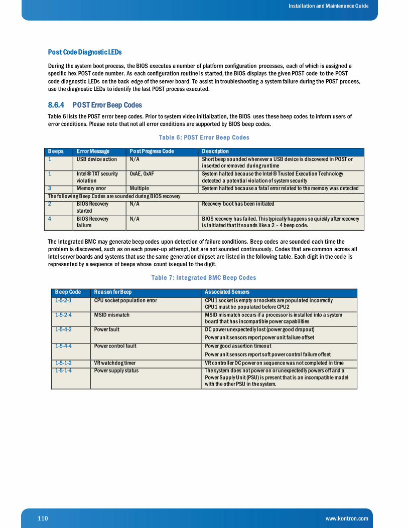
110 www.kontron.com
Installation and Maintenance Guide
Post Code Diagnostic LEDs
During the system boot process, the BIOS executes a number of platform configuration processes, each of which is assigned a
specific hex POST code number. As each configuration routine is started, the BIOS displays the given POST code to the POST
code diagnostic LEDs on the back edge of the server board. To assist in troubleshooting a system failure during the POST process,
use the diagnostic LEDs to identify the last POST process executed.
8.6.4 POST Error Beep Codes
Table 6 lists the POST error beep codes. Prior to system video initialization, the BIOS uses these beep codes to inform users of
error conditions. Please note that not all error conditions are supported by BIOS beep codes.
Table 6 : POS T Er r or Be e p Code s
B eeps E rror Message Po st Progress Code D es cription
1 USB device action N/A Short beep sounded whenever a USB device is discovered in POST or inserted or removed during runtime
1 Intel® TXT security
violation
0xAE, 0xAF System halted because the Intel® Trusted Execution Technology
detected a potential violation of system security
3 Memory error Multiple System halted because a fatal error related to the memory was detected
The following Beep Codes are sounded during BIOS recovery
2 BIOS Recovery
started
N/A Recovery boot has been initiated
4 BIOS Recovery failure
N/A BIOS recovery has failed. This typically happens so quickly after recovery is initiated that it sounds like a 2 – 4 beep code.
The Integrated BMC may generate beep codes upon detection of failure conditions. Beep codes are sounded each time the
problem is discovered, such as on each power-up attempt, but are not sounded continuously. Codes that are common across all
Intel server boards and systems that use the same generation chipset are listed in the following table. Each digit in the code is
represented by a sequence of beeps whose count is equal to the digit.
Table 7 : Int e g r at e d BMC Be e p Code s
B eep Code Rea son for Beep As sociated Sensors
1-5-2-1 CPU socket population error CPU1 socket is empty or sockets are populated incorrectly CPU1 must be populated before CPU2
1-5-2-4 MSID mismatch MSID mismatch occurs if a processor is installed into a system board that has incompatible power capabilities
1-5-4-2 Power fault DC power unexpectedly lost (power good dropout)
Power unit sensors report power unit failure offset
1-5-4-4 Power control fault Power good assertion timeout
Power unit sensors report soft power control failure offset
1-5-1-2 VR watchdog timer VR controller DC power on sequence was not completed in time
1-5-1-4 Power supply status The system does not power on or unexpectedly powers off and a
Power Supply Unit (PSU) is present that is an incompatible model with the other PSU in the system.

111 www.kontron.com
Installation and Maintenance Guide
9 Appendix A: Safety Information
WARNING: Although you may be using this guide or another resource as a reference, before working with your server product pay
close attention to these safety instructions. Always adhere to the assembly instructions in this guide to ensure and maintain
compliance with existing product certifications and approvals. Use only the described, regulated components specified in this
guide. Use of other products / components will void the UL listing and other regulatory approvals of the product and will most
likely result in non-compliance with product regulations in the region(s) in which the product is sold.
9.1 Emissions Disclaimer
To ensure EMC (Electromagnetic Compatibility) compliance with your local regional rules and regulations, the final configuration
of your end system product may require additional EMC compliance testing. For more information, please contact your local
Kontron Representative. See Appendix B, “Regulatory and Certification Information” for product Safety and EMC regulatory
compliance information. This is an FCC (Federal Communications Commission) Class A device.
9.2 Intended Uses
This product was evaluated as Information Technology Equipment (ITE), which may be installed in Central Offices,
Telecommunication Centers, offices, schools, computer rooms, and similar commercial type locations. The suitability of this
product for other product categories and environments (medical, industrial, telecommunications, residential, alarm systems, test
equipment, etc.), other than an ITE application, may require further evaluation.
WARNING: Anchor the equipment rack: The equipment rack must be anchored to an unmovable support to prevent it from falling
over when one or more servers are extended in front of the rack on slides. Always also consider the weight of any other device
installed in the rack. A crush hazard exists should the rack tilt forward which could cause serious injury.
9.2.1 If AC power supplies are installed:
Mains AC power disconnect: The AC power cord(s) is considered the mains disconnect for the server and must be readily
accessible when installed. If the individual server power cord(s) will not be readily accessible for disconnection then you must
install an AC power disconnect for the entire rack unit. This main disconnect must be readily accessible, and it must be labe led
as controlling power to the entire rack, not just to the server(s).
Grounding the rack installation: To avoid the potential for an electrical shock hazard, you must include a third wire safety ground
conductor with the rack installation. If the server power cord is plugged into an AC outlet that is part of the rack, then yo u must
provide proper grounding for the rack itself. If the server power cord is plugged wall AC outlet, the safety ground conductor in the
power cord provides proper grounding only for the server. You must provide additional, proper grounding for the rack and othe r
devices installed in it.
Overcurrent protection: The server is designed for an AC line voltage source with up to 20 amperes of overcurrent protection per
cord feed. If the power system for the equipment rack is installed on a branch circuit with more than 20 amperes of protectio n,
you must provide supplemental protection for the server. The overall current rating of a configured server is less than 6 amperes.
WARNING: Do not attempt to modify or use an AC power cord set that is not the exact type required. You must use a power cord set
that meets the following criteria:
Rating: In the U.S. and Canada, cords must be UL (Underwriters Laboratories, Inc.) Listed/CSA (Canadian Standards
Association) Certified type SJT, 18-3 AWG (American Wire Gauge). Outside of the U.S. and Canada, cords must be flexible
harmonized (<HAR>) or VDE (Verbena Deutscher Electrotechniker, German Institute of Electrical Engineers) certified cord with 3x
0.75 mm conductors rated 250 VAC.
Connector, wall outlet end: Cords must be terminated in grounding-type male plug designed for use in your region. The »
connector must have certification marks showing certification by an agency acceptable in your region and for U.S. must
be listed and rated for 125% of the overall current rating of the server.
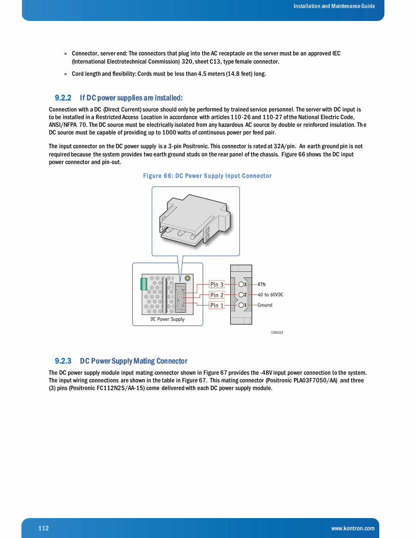
112 www.kontron.com
Installation and Maintenance Guide
Connector, server end: The connectors that plug into the AC receptacle on the server must be an approved IEC »
(International Electrotechnical Commission) 320, sheet C13, type female connector.
Cord length and flexibility: Cords must be less than 4.5 meters (14.8 feet) long. »
9.2.2 If DC power supplies are installed:
Connection with a DC (Direct Current) source should only be performed by trained service personnel. The server with DC input is
to be installed in a Restricted Access Location in accordance with articles 110-26 and 110-27 of the National Electric Code,
ANSI/NFPA 70. The DC source must be electrically isolated from any hazardous AC source by double or reinforced insulation. Th e
DC source must be capable of providing up to 1000 watts of continuous power per feed pair.
The input connector on the DC power supply is a 3-pin Positronic. This connector is rated at 32A/pin. An earth ground pin is not
required because the system provides two earth ground studs on the rear panel of the chassis. Figure 66 shows the DC input
power connector and pin-out.
F ig ur e 6 6 : DC Powe r S upply Input Conne ct or
9.2.3 DC Power Supply Mating Connector
The DC power supply module input mating connector shown in Figure 67 provides the -48V input power connection to the system.
The input wiring connections are shown in the table in Figure 67. This mating connector (Positronic PLA03F7050/AA) and three
(3) pins (Positronic FC112N2S/AA-15) come delivered with each DC power supply module.

113 www.kontron.com
Installation and Maintenance Guide
F ig ur e 6 7 : DC Powe r S upply Mat ing Conne ct or
9.2.4 DC Power Supply Earth Grounding Studs on Chassis
For instructions about how the safety earth grounding wire is attached to the chassis for use with DC power supplies, see Figure
53, ”DC Power Supply Grounding” in Section 5.3.2 “Adding or Replacing a Power Supply Unit”.
Mains DC power disconnect: You are responsible for installing a properly rated DC power disconnect for the server system. This
mains disconnect must be readily accessible, and it must be labeled as controlling power to the server. The UL listed circuit
breaker of a centralized DC power system may be used as a disconnect device when easily accessible and shall be rated
maximum 35 amps.
Grounding the server: This server is intended for installation with an isolated DC return (DC-I per NEBS GR-1089, Issue 3). To
avoid the potential for an electrical shock hazard, you must reliably connect an earth grounding conductor to the server. The earth
grounding conductor must be a minimum 10 AWG connected to the earth ground stud(s) on the rear of the server. The safety
ground conductor should be connected to the chassis stud with a listed closed two-hole crimp terminal having 5/8-inch pitch.
The nuts on the chassis earth ground studs should be installed with a 10 in-lbs of torque. The safety ground conductor provides
proper grounding only for the server. You must provide additional, proper grounding for the rack and other devices installed in it.
9.2.5 Overcurrent protection
Overcurrent protection UL Listed circuit breakers must be provided as part of each host equipment rack and must be
incorporated in the field wiring between the DC source and the server. The branch circuit protection shall be rated minimum 75
VDC, 35A maximum per feed pair.
9.2.6 Temperature and Ventilation
CAUTION: Temperature -- The temperature, in which the server operates when installed in an equipment rack, must not go below
5°C (41°F) or rise above 40°C (104°F). Extreme fluctuations in temperature can cause a variety of problems in the server.
CAUTION: Ventilation -- The equipment rack must provide sufficient airflow to the front of the server to maintain proper cooling.
The rack must also include ventilation sufficient to exhaust a maximum of 1023 BTUs (British Thermal Units) per hour for the
server. The rack selected and the ventilation provided must be suitable to the environment in which the server will be used.
9.3 Safety Cautions
Read all caution and safety statements in this document before performing any of the instructions.

114 www.kontron.com
Installation and Maintenance Guide
The power supply in this product contains no user-serviceable parts. There may be more than one supply in this
product. Refer servicing only to qualified personnel.
Do not attempt to modify or use the supplied AC power cord if it is not the exact type required. A product with more
than one power supply will have a separate AC power cord for each supply.
The power button on the system does not turn off system AC power. To remove AC power from the system, always
unplug each AC power cord from the wall outlet or power supply.
The power cord(s) is considered the disconnect device to the main (AC) power. Th e socket outlet that the system
plugs into must be installed near the equipment and must be easily accessible.
SAFETY STEPS: When removing the chassis covers to access the inside of the system, follow these steps:
1. Turn off all peripheral devices connected to the system.
2. Turn off the system by pressing the power button.
3. Unplug all AC power cords from the system or from wall outlets.
4. Label and disconnect all cables connected to I/O connectors or ports on the back of the system.
5. Provide electrostatic discharge (ESD) protection by wearing an antistatic wrist strap attached to chassis ground of
the system—any unpainted metal surface—when handling components.
After completing the six SAFETY STEPS above, you can remove the system covers. To do this:
1. Unlock and remove the padlock from the back of the system if a padlock has been installed.
2. Remove and save all screws from the covers.
3. Remove the covers.
4. Do not operate the system with the chassis covers removed.
For proper cooling and airflow, always reinstall the chassis covers before turning on the system. Operating the system without the covers in place can damage system parts. To install the covers:
1. Check first to make sure no loose tools or parts were left inside the system.
2. Check that cables, add-in boards, and other components are properly installed.
3. Attach the covers to the chassis with the screws removed earlier, and tighten them firmly.
4. Insert and lock the padlock to the system to prevent unauthorized access inside the system.
5. Connect all external cables and the AC power cord(s) to the system.
A microprocessor and heat sink may be hot if the system has been running. Also, there may be sharp pins and edges on some board and chassis parts. Contact should be made with care. Consider wearing protective gloves.
Danger of explosion if the battery is incorrectly replaced. Replace only with the same or equivalent type recommended by the equipment manufacturer. Dispose of used batteries according to man ufacturer’s instructions.
The system is designed to operate in a typical office environment. Choose a site that is:
Clean and free of airborne particles (other than normal room dust). »
Well ventilated and away from sources of heat including direct sunlight.
Away from sources of vibration or physical shock. »

115 www.kontron.com
Installation and Maintenance Guide
Isolated from strong electromagnetic fields produced by electrical devices. »
In regions that are susceptible to electrical storms, we recommend plugging the system into a surge »
suppressor and disconnecting telecommunication lines to the modem during an electrical storm.
Provided with a properly grounded wall outlet. »
Provided with sufficient space to access the power supply cord(s), because they serve as the product’s »
main power disconnect.
9.3.1 Wichtige Sicherheitshinweise
Lesen Sie zunächst sämtliche Warn- und Sicherheitshinweise in diesem Dokument, bevor Sie eine der Anweisungen ausführen.
Benutzer können am Netzgerät dieses Produkts keine Reparaturen vornehmen. Das Produkt enthält möglicherweise
mehrere Netzgeräte. Wartungsarbeiten müssen von qualifizierten Technikern ausgeführt werden.
Versuchen Sie nicht, das mitgelieferte Netzkabel zu ändern oder zu verwenden, wenn es sich nicht genau um den
erforderlichen Typ handelt. Ein Produkt mit mehreren Netzgeräten hat für jedes Netzgerät ein eigenes Netzkabel.
Der Wechselstrom des Systems wird durch den Ein-/Aus-Schalter für Gleichstrom nicht ausgeschaltet. Ziehen Sie
jedes Wechselstrom-Netzkabel aus der Steckdose bzw. dem Netzgerät, um den Stromanschluß des Systems zu
unterbrechen.
SICHERHEISMASSNAHMEN: Immer wenn Sie die Gehäuseabdeckung abnehmen um an das Systeminnere zu gelangen, sollten Sie folgende Schritte beachten:
1. Schalten Sie alle an Ihr System angeschlossenen Peripheriegeräte aus.
2. Schalten Sie das System mit dem Hauptschalter aus.
3. Ziehen Sie den Stromanschlußstecker Ihres Systems aus der Steckdose.
4. Auf der Rückseite des Systems beschriften und ziehen Sie alle Anschlußkabel von den I/O Anschlüssen oder
Ports ab.
5. Tragen Sie ein geerdetes Antistatik Gelenkband, um elektrostatische Ladungen (ESD) über blanke Metallstellen bei der Handhabung der Komponenten zu vermeiden.
6. Schalten Sie das System niemals ohne ordnungsgemäß montiertes Gehäuse ein.
Nachdem Sie die oben erwähnten ersten sechs SICHERHEITSSCHRITTE durchgeführt haben, können Sie die
Abdeckung abnehmen, indem Sie:
1. Öffnen und entfernen Sie die Verschlußeinrichtung (Padlock) auf der Rückseite des Systems, falls eine Verschlußeinrichtung installiert ist.
2. Entfernen Sie alle Schrauben der Gehäuseabdeckung.
3. Nehmen Sie die Abdeckung ab.
Zur ordnungsgemäßen Kühlung und Lüftung muß die Gehäuseabdeckung immer wieder vor dem Einschalten
installiert werden. Ein Betrieb des Systems ohne angebrachte Abdeckung kann Ihrem System oder Teile darin
beschädigen. Um die Abdeckung wieder anzubringen:
1. Vergewissern Sie sich, daß Sie keine Werkzeuge oder Teile im Innern des Systems zurückgelassen haben.

116 www.kontron.com
Installation and Maintenance Guide
2. Überprüfen Sie alle Kabel, Zusatzkarten und andere Komponenten auf ordnungsgemäßen Sitz und Installation.
3. Bringen Sie die Abdeckungen wieder am Gehäuse an, indem Sie die zuvor gelösten Schrauben wieder anbringen.
Ziehen Sie diese gut an.
4. Bringen Sie die Verschlußeinrichtung (Padlock) wieder an und schließen Sie diese, um ein unerlaubtes Öffnen
des Systems zu verhindern.
5. Schließen Sie alle externen Kabel und den AC Stromanschlußstecker Ihres Systems wieder an.
Der Mikroprozessor und der Kühler sind möglicherweise erhitzt, wenn das System in Betrieb ist. Außerdem können
einige Platinen und Gehäuseteile scharfe Spitzen und Kanten aufweisen. Arbeiten an Platinen und Gehäuse sollten
vorsichtig ausgeführt werden. Sie sollten Schutzhandschuhe tragen.
Bei falschem Einsetzen einer neuen Batterie besteht Explosionsgefahr. Die Batterie darf nur durch denselben oder
einen entsprechenden, vom Hersteller empfohlenen Batterietyp ersetzt werden. Entsorgen Sie verbrauchte Batterien
den Anweisungen des Herstellers entsprechend.
Das System wurde für den Betrieb in einer normalen Büroumgebung entwickelt. Der Standort sollte:
• sauber und staubfrei sein (Hausstaub ausgenommen);
• gut gelüftet und keinen Heizquellen ausgesetzt sein (einschließlich direkter Sonneneinstrahlung);
• keinen Erschütterungen ausgesetzt sein;
• keine starken, von elektrischen Geräten erzeugten elektromagnetischen Felder aufweisen;
• in Regionen, in denen elektrische Stürme auftreten, mit einem Überspannungsschutzgerät verbunden sein;
während eines elektrischen Sturms sollte keine Verbindung der Telekommunikationsleitungen mit dem Modem
bestehen;
• mit einer geerdeten Wechselstromsteckdose ausgerüstet sein;
• über ausreichend Platz verfügen, um Zugang zu den Netzkabeln zu gewährleisten, da der Stromanschluß des
Produkts hauptsächlich über die Kabel unterbrochen wird.
9.3.2 Consignes de sécurité
Lisez attention toutes les consignes de sécurité et les mises en garde indiquées dans ce document avant de suivre toute
instruction.
Le bloc d’alimentation de ce produit ne contient aucune pièce pouvant être réparée par l'utilisateur. Ce produit
peut contenir plus d’un bloc d'alimentation. Veuillez contacter un technicien qualifié en cas de problème.
Ne pas essayer d’utiliser ni modifier le câble d’alimentation CA fourni, s’il ne correspond pas exactement au type
requis. Le nombre de câbles d’alimentation CA fournis correspond au nombre de blocs d’alimentation du produit.
Notez que le commutateur CC de mise sous tension /hors tension du panneau avant n’éteint pas l’alimentation CA
du système. Pour mettre le système hors tension, vous devez débrancher chaque câble d’alimentation de sa prise.
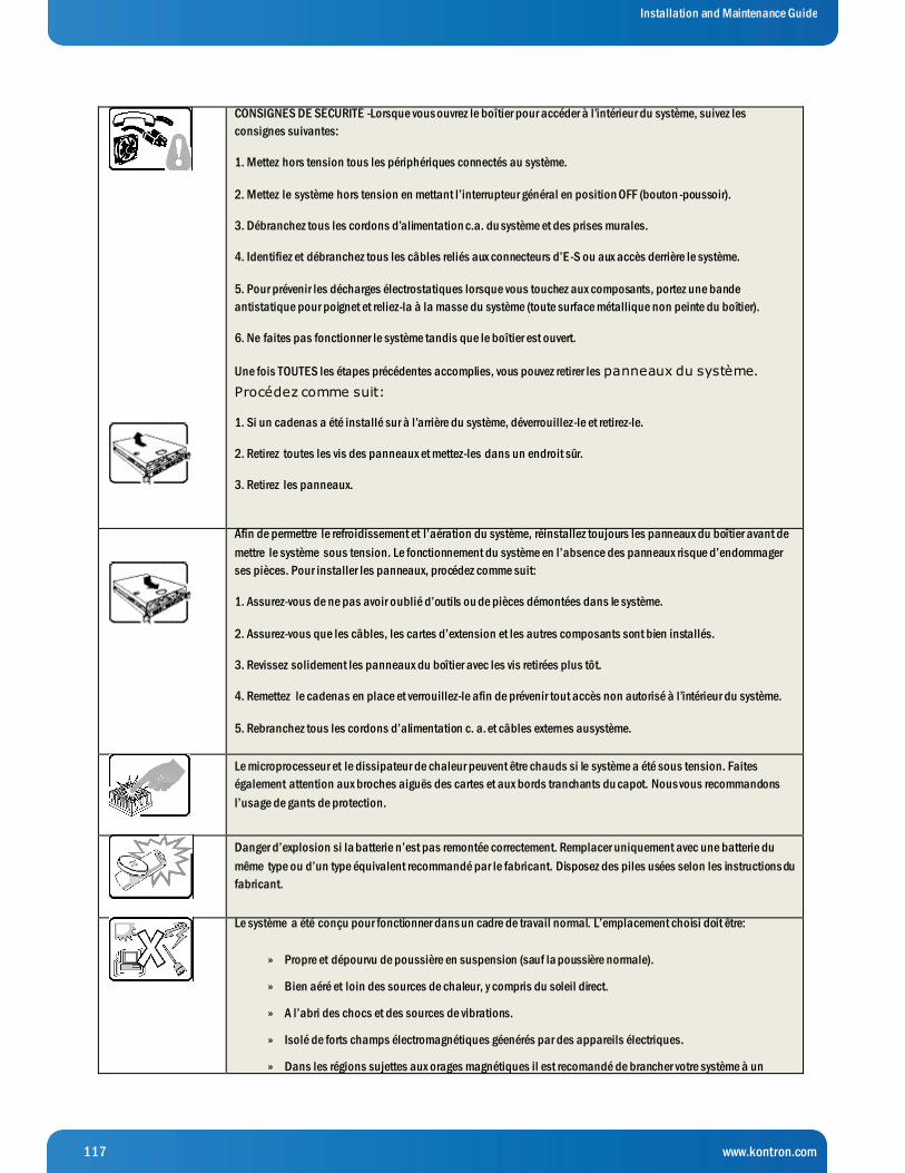
117 www.kontron.com
Installation and Maintenance Guide
CONSIGNES DE SÉCURITÉ -Lorsque vous ouvrez le boîtier pour accéder à l’intérieur du système, suivez les
consignes suivantes:
1. Mettez hors tension tous les périphériques connectés au système.
2. Mettez le système hors tension en mettant l’interrupteur général en position OFF (bouton -poussoir).
3. Débranchez tous les cordons d’alimentation c.a. du système et des prises murales.
4. Identifiez et débranchez tous les câbles reliés aux connecteurs d’E -S ou aux accès derrière le système.
5. Pour prévenir les décharges électrostatiques lorsque vous touchez aux composants, portez une bande
antistatique pour poignet et reliez-la à la masse du système (toute surface métallique non peinte du boîtier).
6. Ne faites pas fonctionner le système tandis que le boîtier est ouvert.
Une fois TOUTES les étapes précédentes accomplies, vous pouvez retirer les panneaux du système.
Procédez comme suit:
1. Si un cadenas a été installé sur à l’arrière du système, déverrouillez-le et retirez-le.
2. Retirez toutes les vis des panneaux et mettez-les dans un endroit sûr.
3. Retirez les panneaux.
Afin de permettre le refroidissement et l’aération du système, réinstallez toujours les panneaux du boîtier avant de
mettre le système sous tension. Le fonctionnement du système en l’absence des panneaux risque d’endommager
ses pièces. Pour installer les panneaux, procédez comme suit:
1. Assurez-vous de ne pas avoir oublié d’outils ou de pièces démontées dans le système.
2. Assurez-vous que les câbles, les cartes d’extension et les autres composants sont bien installés.
3. Revissez solidement les panneaux du boîtier avec les vis retirées plus tôt.
4. Remettez le cadenas en place et verrouillez-le afin de prévenir tout accès non autorisé à l’intérieur du système.
5. Rebranchez tous les cordons d’alimentation c. a. et câbles externes ausystème.
Le microprocesseur et le dissipateur de chaleur peuvent être chauds si le système a été sous tension. Faites
également attention aux broches aiguës des cartes et aux bords tranchants du capot. Nous vous recommandons
l’usage de gants de protection.
Danger d’explosion si la batterie n’est pas remontée correctement. Remplacer uniquement avec une batterie du
même type ou d’un type équivalent recommandé par le fabricant. Disposez des piles usées selon les instructions du
fabricant.
Le système a été conçu pour fonctionner dans un cadre de travail normal. L’emplacement choisi doit être:
Propre et dépourvu de poussière en suspension (sauf la poussière normale). »
Bien aéré et loin des sources de chaleur, y compris du soleil direct. »
A l’abri des chocs et des sources de vibrations. »
Isolé de forts champs électromagnétiques géenérés par des appareils électriques. »
Dans les régions sujettes aux orages magnétiques il est recomandé de brancher votre système à un »
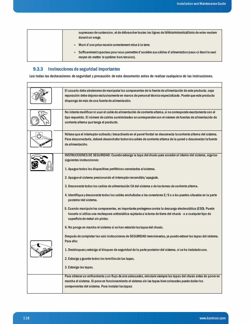
118 www.kontron.com
Installation and Maintenance Guide
supresseur de surtension, et de débrancher toutes les lignes de télécommunications de votre modem
durant un orage.
Muni d’une prise murale correctement mise à la terre. »
Suffisamment spacieux pour vous permettre d’accéder aux câbles d’alimentation (ceux-ci étant le seul »
moyen de mettre le système hors tension).
9.3.3 Instrucciones de seguridad importantes
Lea todas las declaraciones de seguridad y precaución de este documento antes de realizar cualquiera de las instrucciones.
El usuario debe abstenerse de manipular los componentes de la fuente de alimentación de este producto, cuya
reparación debe dejarse exclusivamente en manos de personal técnico especializado. Puede que este producto
disponga de más de una fuente de alimentación.
No intente modificar ni usar el cable de alimentación de corriente alterna, si no corresponde exactamente con el
tipo requerido. El número de cables suministrados se corresponden con el número de fuentes de alimentación de
corriente alterna que tenga el producto.
Nótese que el interruptor activado/desactivado en el panel frontal no desconecta la corriente alterna del sistema.
Para desconectarla, deberá desenchufar todos los cables de corriente alterna de la pared o desconectar la fuente
de alimentación.
INSTRUCCIONES DE SEGURIDAD: Cuando extraiga la tapa del chasis para acceder al interior del sistema, siga las
siguientes instrucciones:
1. Apague todos los dispositivos periféricos conectados al sistema.
2. Apague el sistema presionando el interruptor encendido/apagado.
3. Desconecte todos los cables de alimentación CA del sistema o de las tomas de corriente alterna.
4. Identifique y desconecte todos los cables enchufados a los conectores E/S o a los puertos situados en la parte
posterior del sistema.
5. Cuando manipule los componentes, es importante protegerse contra la descarga electrostática (ESD). Puede
hacerlo si utiliza una muñequera antiestática sujetada a la toma de tierra del chasis - o a cualquier tipo de
superficie de metal sin pintar.
6. No ponga en marcha el sistema si se han extraído las tapas del chasis.
Después de completar las seis instrucciones de SEGURIDAD mencionadas, ya puede extraer las tapas del sistema.
Para ello:
1. Desbloquee y extraiga el bloqueo de seguridad de la parte posterior del sistema, si se ha instalado uno.
2. Extraiga y guarde todos los tornillos de las tapas.
3. Extraiga las tapas.
Para obtener un enfriamiento y un flujo de aire adecuados, reinstale siempre las tapas del chasis antes de poner en
marcha el sistema. Si pone en funcionamiento el sistema sin las tapas bien colocadas puede dañar los
componentes del sistema. Para instalar las tapas:
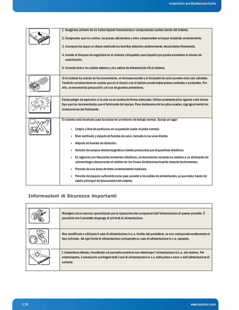
119 www.kontron.com
Installation and Maintenance Guide
1. Asegúrese primero de no haber dejado herramientas o componentes sueltos dentro del sistema.
2. Compruebe que los cables, las placas adicionales y otros componentes se hayan instalado correctamente.
3. Incorpore las tapas al chasis mediante los tornillos extraídos anteriormente, tensándolos firmemente.
4. Inserte el bloqueo de seguridad en el sistema y bloquéelo para impedir que pueda accederse al mismo sin
autorización.
5. Conecte todos los cables externos y los cables de alimentación CA al sistema.
Si el sistema ha estado en funcionamiento, el microprocesador y el disipador de calor pueden estar aún calientes.
También conviene tener en cuenta que en el chasis o en el tablero puede haber piezas cortantes o punzantes. Por
ello, se recomienda precaución y el uso de guantes protectores.
Existe peligro de explosión si la pila no se cambia de forma adecuada. Utilice solamente pilas iguales o del mismo
tipo que las recomendadas por el fabricante del equipo. Para deshacerse de las pilas usadas, siga igual mente las
instrucciones del fabricante.
El sistema está diseñado para funcionar en un entorno de trabajo normal. Escoja un lugar:
Limpio y libre de partículas en suspensión (salvo el polvo normal). »
Bien ventilado y alejado de fuentes de calor, incluida la luz solar directa. »
Alejado de fuentes de vibración. »
Aislado de campos electromagnéticos fuertes producidos por dispositivos eléctricos. »
En regiones con frecuentes tormentas eléctricas, se recomienda conectar su sistema a un eliminador de »
sobrevoltage y desconectar el módem de las líneas de telecomunicación durante las tormentas.
Provisto de una toma de tierra correctamente instalada. »
Provisto de espacio suficiente como para acceder a los cables de alimentación, ya que éstos hacen de »
medio principal de desconexión del sistema.
Informazioni di Sicurezza importanti
Rivolgersi ad un tecnico specializzato per la riparazione dei component dell’alimentazione di questo prodotto. È
possibile che il prodotto disponga di più fonti di alimentazione.
Non modificare o utilizzare il cavo di alimentazione in c.a. fornito dal produttore, se non corrisponde esattamente al
tipo richiesto. Ad ogni fonte di alimentazione corrisponde un cavo di alimentazione in c.a. separato.
L’interruttore attivato/disattivato nel pannello anteriore non interrompe l’alimentazione in c.a. del sistema. Per
interromperla, è necessario scollegare tutti I cavi di alimentazione in c.a. dalle prese a muro o dall’alimentazione di
corrente.

120 www.kontron.com
Installation and Maintenance Guide
PASSI DI SICUREZZA: Qualora si rimuovano le coperture del telaio per accedere all’interno del sistema, seguire i
seguenti passi:
1. Spegnere tutti i dispositivi periferici collegati al sistema.
2. Spegnere il sistema, usando il pulsante spento/acceso dell’interruttore del sistema.
3. Togliere tutte le spine dei cavi del sistema dalle prese elettriche.
4. Identificare e sconnettere tutti i cavi attaccati ai collegamenti I/O od alle prese installate sul retro del sistema.
5. Qualora si tocchino i componenti, proteggersi dallo scarico elettrostatico (SES), portando un cinghia anti -statica
da polso che è attaccata alla presa a terra del telaio del sistema - qualsiasi superficie non dipinta - .
6. Non far operare il sistema quando il telaio è senza le coperture.
Dopo aver seguito i sei passi di SICUREZZA sopracitati, togliere le coperture del telaio del sistema come seque:
1. Aprire e rimuovere il lucchetto dal retro del sistema qualora ve ne fosse uno installato.
2. Togliere e mettere in un posto sicuro tutte le viti delle coperture.
3. Togliere le coperture.
Per il giusto flusso dell’aria e raffreddamento del sistema, rimettere sempre le coperture del telaio prima di
riaccendere il sistema. Operare il sistema senza le coperture al loro proprio posto potrebbe danneggiare i
componenti del sistema. Per rimettere le coperture del telaio:
1. Controllare prima che non si siano lasciati degli attrezzi o dei component dentro il sistema.
2. Controllare che i cavi, dei supporti aggiuntivi ed altri componenti siano stati installati appropriatamente.
3. Attaccare le coperture al telaio con le viti tolte in precedenza e avvitarle strettamente.
4. Inserire e chiudere a chiave il lucchetto sul retro del sistema per impedire l’accesso non autorizzato al sistema.
5. Ricollegare tutti i cavi esterni e le prolunghe AC del sistema.
Se il sistema è stato a lungo in funzione, il microprocessore e il dissipatore di calore potrebbero essere
surriscaldati. Fare attenzione alla presenza di piedini appuntiti e parti taglienti sulle schede e sul telaio. È
consigliabile l’uso di guanti di protezione.
Esiste il pericolo di un esplosione se la pila non viene sostituita in modo corretto. Utilizzare solo pile uguali o di tipo
equivalente a quelle consigliate dal produttore. Per disfarsi delle pile usate, seguire le istruzioni del produttore.
Il sistema è progettato per funzionare in un ambiente di lavoro tipo. Scegliere una postazione che sia:
Pulita e libera da particelle in sospensione (a parte la normale polvere p resente nell’ambiente). »
Ben ventilata e lontana da fonti di calore, compresa la luce solare diretta. »
Al riparo da urti e lontana da fonti di vibrazione. »
Isolata dai forti campi magnetici prodotti da dispositivi elettrici. »
In aree soggette a temporali, è consigliabile collegare il sistema ad un limitatore di corrente. In caso di »
temporali, scollegare le linee di comunicazione dal modem.

121 www.kontron.com
Installation and Maintenance Guide
Dotata di una presa a muro correttamente installata. »
Dotata di spazio sufficiente ad accedere ai cavi di alimentazione, i quail rappresentano il mezzo »
principale di scollegamento del sistema.

122 www.kontron.com
Installation and Maintenance Guide
10 Appendix B: Regulatory and Certification Information
10.1 Product Regulatory Compliance
10.1.1 Product Safety Compliance
The Carrier Grade server complies with the following safety requirements:
UL60950-1 /CSA 60950-1 (USA / Canada) »
EN60950-1 (Europe) »
IEC60950-1 (International), CB Certificate & Report including all international deviations »
CU Approvals (EAC Mark) (Armenia, Belarus, Kazakhstan, Kyrgyzstan, Russia) »
CE - Low Voltage Directive 2006/95/EC (Europe) »
10.1.2 Product EMC Compliance - Class A Compliance
The Carrier Grade server has been tested and verified to comply with the following electromagnetic compatibility (EMC)
regulations.
FCC Part 15 / ICES-003 - Emissions (USA/Canada) »
CISPR 22 - Emissions (International) »
CISPR 24 – Immunity (International) »
EN55022 - Emissions (Europe) »
EN55024 - Immunity (Europe) »
EN61000-3-2 - Harmonics (Europe) »
EN61000-3-3 - Voltage Flicker (Europe) »
CE- EMC Directive 2004/108/EC (Europe) »
AS/NZS: CISPR 22 Emissions (Australia / New Zealand) »
CU Approvals (EAC Mark) (Armenia, Belarus, Kazakhstan, Kyrgyzstan, Russia) »
KN22 (Korea) »
KN24 (Korea) »
10.1.3 Marking
cULus Listed (US/Canada) »
CE Mark (Europe) »
RCM Mark (Australia and New Zealand) (replaces C-Tick) »
EAC Mark (Russia) »
KCC Mark (Korea) »
NOTE: Marks above are found on CG2300 Safety Label (on unit top cover)
10.1.4 Environmental Compliance
WEEE »
REACH »

123 www.kontron.com
Installation and Maintenance Guide
RoHS »
China RoHS »
10.2 Electromagnetic Compatibility Notices
10.2.1 FCC (USA)
This device complies with Part 15 of the FCC Rules. Operation is subject to the following two conditions: (1) this device may not
cause harmful interference, and (2) this device must accept any interference received, including interference that may cause
undesired operation.
For questions related to the EMC performance of this product, contact:
Kontron America, Inc.
14118 Stowe Drive
Poway, CA 92064-7147
(888) 294-4558
This equipment has been tested and found to comply with the limits for a Class A digital device, pursuant to Part 15 of the F CC
Rules. These limits are designed to provide reasonable protection against harmful interference in a residential installation. This
equipment generates, uses, and can radiate radio frequency energy and, if not installed and used in accordance with the
instructions, may cause harmful interference to radio communications. However, there is no guarantee that interference will not
occur in a particular installation. If this equipment does cause harmful interference to radio or television reception, which can be
determined by turning the equipment off and on, the user is encouraged to try to correct the interference by one or more of the
following measures:
Reorient or relocate the receiving antenna. 1.
Increase the separation between the equipment and the receiver. 2.
Connect the equipment to an outlet on a circuit other than the one to which the receiver is connected. 3.
Consult the dealer or an experienced radio/TV technician for help. 4.
Any changes or modifications not expressly approved by the grantee of this device could void the user's authority to operate the
equipment. The customer is responsible for ensuring compliance of the modified product.
Only peripherals (computer input/output devices, terminals, printers, etc.) that comply with FCC Class A or B limits may be
attached to this computer product. Operation with noncompliant peripherals is likely to result in interference to radio and TV
reception.
All cables used to connect to peripherals must be shielded and grounded. Operation with cables connected to peripherals that
are not shielded and grounded may result in interference to radio and TV reception.
10.2.2 Industry Canada (ICES-003)
Cet appareil numérique respecte les limites bruits radioélectriques applicables aux appareils numériques de Classe A prescrit es
dans la norme sur le matériel brouilleur: “Appareils Numériques”, NMB-003 édictée par le Ministre Canadian des
Communications.
English translation of the notice above:
This digital apparatus does not exceed the Class A limits for radio noise emissions from digital apparatus set out in the
interference-causing equipment standard entitled “Digital Apparatus”, ICES-003 of the Canadian Department of
Communications.
124 www.kontron.com
Installation and Maintenance Guide
10.2.3 Europe (CE Declaration of Conformity)
This product has been tested in accordance to, and complies with, the Low Voltage Directive (73/23/EEC) and EMC Directive
(2004/108/EC). The product has been marked with the CE Mark to illustrate its compliance.
10.2.4 VCCI (Japan)
English translation of the notice above:
This is a Class A product based on the standard of the Voluntary Control Council for Interference (VCCI) from Information
Technology Equipment. If this is used near a radio or television receiver in a domestic environment, it may cause radio
interference.
Install and use the equipment according to the instruction manual.
10.2.5 BSMI (Taiwan)
The BSMI Certification Marking and EMC warning is located on the outside rear area of the product.
10.2.6 Regulated Specified Components
To maintain the UL listing and compliance to other regulatory certifications and/or declarations, the following conditions must
be adhered to and the following regulated components must be used. Interchanging or using other components will void the UL
listing and other product certifications and approvals.
1. Add-in boards must have a printed wiring board flammability rating of minimum UL94V-1. Add-in boards containing external
power connectors and/or lithium batteries must be UL recognized or UL listed. Any add-in board containing modem
telecommunication circuitry must be UL listed. In addition, the modem must have the appropriate telecommunications,
safety, and EMC approvals for the region in which it is sold.
2. Peripheral Storage Devices must be a UL recognized or UL listed accessory and TUV or VDE licensed. Maximum power rating
of any one device is 19 watts. Total server configuration is not to exceed the maximum loading conditions of the power
supply.

125 www.kontron.com
Installation and Maintenance Guide
11 Appendix C: NEBS Considerations
WARNING: The CG2300 server intra-building Ethernet RJ-45 ports, COM ports, and/or Telco Alarms port are suitable for
connection to intra-building or unexposed wiring or cabling only. The intra-building ports of the CG2300 MUST NOT be
metallically connected to interfaces that connect to the OSP or its wiring. These interfaces are designed for use as intra -building
interfaces only (Type 2 or Type 4 ports as described in GR-1089) and require isolation from the exposed OSP cabling. The
addition of Primary Protectors is not sufficient protection in order to connect these interfaces metallically to OSP wiring.
WARNING: The CG2300 server intra-building Ethernet RJ-45 ports, COM ports, and/or Telco Alarms port must use shielded intra-
building cabling/wiring that is grounded at both ends.
The CG2300 server is suitable for installation in either the Common Bonding Network (CBN) or an Isolated Bonding Network
(IBN).
The CG2300 server is suitable for installation in Network Telecommunication Facilities (NTF) and locations where the National
Electric Code (NEC) applies, but is not suitable for installation in Outside Plant (OSP) installations.
The Battery Return (BR) for the -48V DC powered CG2300 systems is suitable for installation as either Isolation DC return (DC-I)
or Common DC return (DC-C). Where the CG2300 is installed with a common DC return, the ampacity of the conductor
connecting the equipment frame to the battery return conductor shall be equal to or greater than 13 amps.
The CG2300 server can be configured with an optional air filter that is installed behind the front bezel.
The air filter material is UAF Quadrafoam (25 PPI), has a thickness of 6.35mm, flammability rating of UL94 -HF1, and meets the
minimum dust arrestance of 65% (ASHRAE 52.1-1992) per documentation found at http://www.uaf.com. The air filter can be
purchased directly from Universal Air Filter (UAF) by calling (618) 271-7300 or emailing [email protected] and ordering part number
K00737-001. When placing an order provide the attached drawing to verify receipt of the proper air filter.
Recommended Air Filter Replacement Schedule: Every 6 months
The CG2300 server is equipped with thermal sensors to monitor the internal temperature of the system. If the air filter gets
clogged so that the fans are not able to pull air through the system, the internal temperature will rise causing a MNR and/or MJR
telco alarms manager (TAM) LED to be asserted. This active alarm provides an indication that the air filter should be inspected
and/or replaced.
126 www.kontron.com
Installation and Maintenance Guide
12 Appendix D: Getting Help
12.1 World Wide Web
Technicians and engineers from Kontron and/or its subsidiaries are available for technical support. We are committed to makin g
our product easy to use and will help you use our products in your systems.
Please consult our Web site at http://www.kontron.com/support-and-services/support/contact-support for the latest
product documentation, utilities, drivers and support contacts.
127 www.kontron.com
Installation and Maintenance Guide
Corporate Offices
Europe, Middle East & Africa North America Asia Pacific Lise-Meitner-Str. 3-5
86156 Augsburg
Germany
Tel.: + 49 821 40 860
Fax: + 49 821 40 860 111
14118 Stowe Drive
Poway, CA 92064-7147
USA
Tel.: + 1 888 294 4558
Fax: + 1 858 677 0898
1~2F, 10 Building, No. 8
Liangshuihe 2nd Street
Beijing 100176, P. R. China
Tel.: + 86 10 63751188
Fax.: + 86 10 83682438