contentsclientes.wandertech.com.br/wa_files/manualplaca_pegatron_ipm31_pc... · ipm31 motherboard...
TRANSCRIPT
IPM31Motherboard layout reference
Contents
• Specifications summary• Motherboard layout• Rear panel connectors• Function selectors• Internal connectors
2IPM31 motherboard layout reference
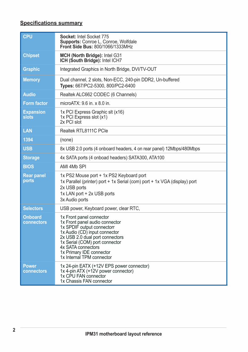
Specifications summary
CPU Socket: Intel Socket 775 Supports: Conroe L, Conroe, Wolfdale Front Side Bus: 800/1066/1333MHz
Chipset MCH (North Bridge): Intel G31 ICH (South Bridge): Intel ICH7
Graphic Integrated Graphics in North Bridge, DVI/TV-OUT
Memory Dual channel, 2 slots, Non-ECC, 240-pin DDR2, Un-buffered Types: 667/PC2-5300, 800/PC2-6400
Audio Realtek ALC662 CODEC (6 Channels)
Form factor microATX: 9.6 in. x 8.0 in.
Expansion slots
1x PCI Express Graphic slt (x16) 1x PCI Express slot (x1) 2x PCI slot
LAN Realtek RTL8111C PCIe
1394 (none)
USB 8x USB 2.0 ports (4 onboard headers, 4 on rear panel) 12Mbps/480Mbps
Storage 4x SATA ports (4 onboad headers) SATA300, ATA100
BIOS AMI 4Mb SPI
Rear panel ports
1x PS2 Mouse port + 1x PS2 Keyboard port 1x Parallel (printer) port + 1x Serial (com) port + 1x VGA (display) port 2x USB ports 1x LAN port + 2x USB ports 3x Audio ports
Selectors USB power, Keyboard power, clear RTC,
Onboard connectors
1x Front panel connector 1x Front panel audio connector 1x SPDIF output connectorr 1x Audio (CD) input connector 2x USB 2.0 dual port connectors 1x Serial (COM) port connector 4x SATA connectors 1x Primary IDE connector 1x Internal TPM connector
Power connectors
1x 24-pin EATX (+12V EPS power connector) 1x 4-pin ATX (+12V power connector) 1x CPU FAN connector 1x Chassis FAN connector
1x Front panel audio header 1x System chassis speaker header 1x System chassis intrusion header
3IPM31 motherboard layout reference
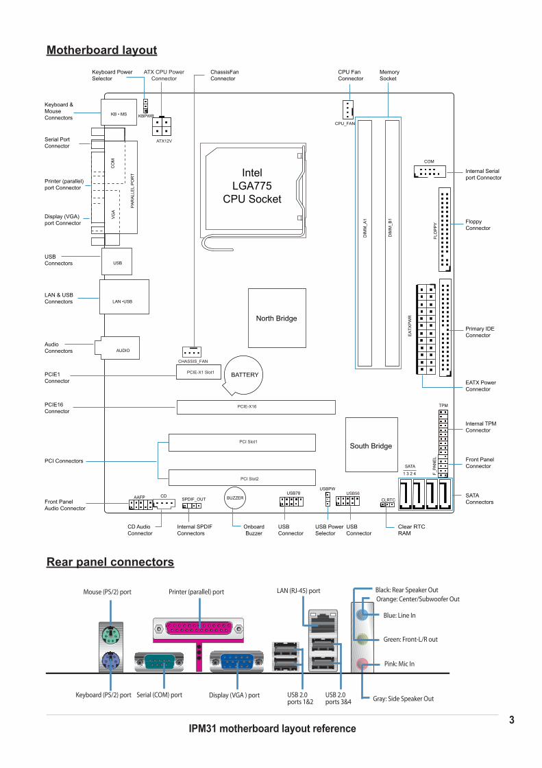
Orange: Center/Subwoofer OutBlack: Rear Speaker Out
Pink: Mic In
Blue: Line In
Green: Front-L/R out
Motherboard layout
Rear panel connectors
Gray: Side Speaker Out
Mouse (PS/2) port
Display (VGA ) port
Printer (parallel) port
Keyboard (PS/2) port
LAN (RJ-45) port
Serial (COM) port USB 2.0ports 3&4
USB 2.0 ports 1&2
IntelLGA775
CPU Socket
PCIE1Connector
PCIE16Connector
PCI Connectors
Front PanelAudio Connector
Keyboard &MouseConnectors
USBConnectors
LAN & USBConnectors
AudioConnectors
Display (VGA)port Connector
Printer (parallel)port Connector
Serial PortConnector
MemorySocket
CPU FanConnector
ChassisFanConnector
ATX CPU PowerConnector
Keyboard PowerSelector
Internal Serialport Connector
EATX PowerConnector
SATAConnectors
Front PanelConnector
Floppy Connector
Primary IDEConnector
OnboardBuzzer
Clear RTCRAM
USBConnector
USBConnector
USB PowerSelector
Internal SPDIFConnectors
CD AudioConnector
SPDIF_OUTCDAAFP
USBPW
BUZZERUSB78 USB56
CLRTC
F_PA
NEL
SATA
1 3 2 4
PCI Slot1
PCI Slot2
PCIE-X16
North Bridge
BATTERY
KB • MS
DIM
M_A
1
DIM
M_B
1
CHASSIS_FAN
LAN •USB
ATX12V
AUDIO
CPU_FAN
EA
TXP
WR
FLO
PP
Y
COM
KBPWRC
OM
VG
A
PA
RA
LLE
L P
OR
T
USB
PCIE-X1 Slot1
Internal TPMConnector
TPM
South Bridge
4IPM31 motherboard layout reference
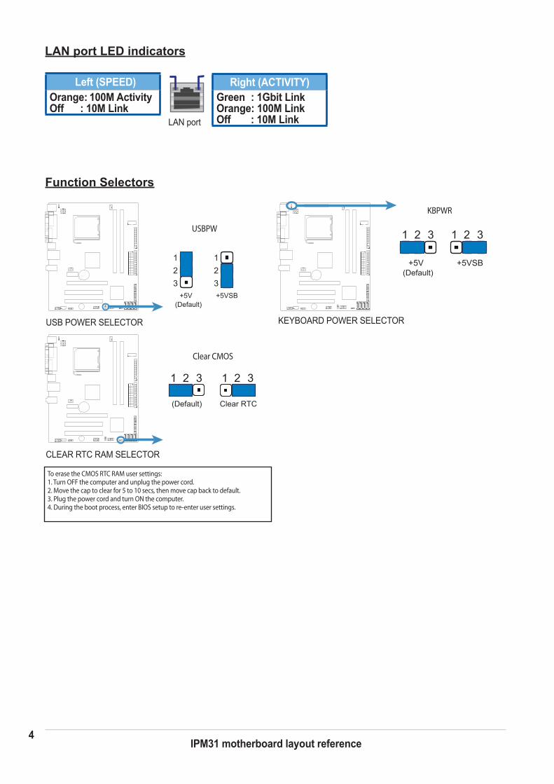
Left (SPEED)Orange: 100M Activity Off : 10M Link
Right (ACTIVITY)Green : 1Gbit LinkOrange: 100M LinkOff : 10M LinkLAN port
LAN port LED indicators
Function Selectors
KEYBOARD POWER SELECTOR USB POWER SELECTOR
CLEAR RTC RAM SELECTOR
USBPW
(Default)+5V +5VSB
321
321
1 32
+5V +5VSB(Default)
1 32
KBPWR
1 32 1 32
(Default) Clear RTC
Clear CMOS
KBPWR
USBPW
Clear CMOS
To erase the CMOS RTC RAM user settings:1. Turn OFF the computer and unplug the power cord.2. Move the cap to clear for 5 to 10 secs, then move cap back to default.3. Plug the power cord and turn ON the computer.4. During the boot process, enter BIOS setup to re-enter user settings.

5IPM31 motherboard layout reference
Internal connectors
CPU FAN CONNECTOR
SATA CONNECTORS
ATX 12V POWER CONNECTOR EATX POWER CONNECTOR
USB CONNECTORSFRONT PANEL AUDIO CONNECTOR
EATX PWR+3 Volts
Power OK
Ground
Ground
Ground
Ground
GroundGroundGround
GroundPSON#
+5 Volts+5 Volts
+5 Volts
5 Volts
12 Volts
+3 Volts
+12 Volts+12 Volts
+5V Standby
+5 Volts
+5 Volts
+3 Volts+3 Volts
SPDIF AUDIO OUT CONNECTORFLOPPY CONNECTOR
ATX12V
+12V DCGround Ground
+12V DC
CPU_FANGround
+12VFAN_TACHFAN_PWM
Gro
und
SP
DIF
out
+5V
Ground
Ground
Ground
SATA_RX(+)SATA_RX(-)
SATA_TX(-)SATA_TX(+)
US
B*(
-)U
SB
*(+)
US
B*(
+)U
SB
*(-)
Gro
und
Gro
und
SB
VS
BV
NC
MIC
*_L
MIC
*_R
LIN
E*_
RG
roun
d
Gro
und
LIN
E*_
LLI
NE
*_JD
MIC
*_JD
AU
DIO
_PR
ES
#
AAFP
FLOPPY
USB78 USB56
ATX12V
SPDIF_OUT
CPU_FAN
EATX PWR
AAFP
SATA
CHASSIS FAN CONNECTOR
CHASSIS_FAN
Gro
und
+12V
FAN
_TA
CH
FAN
_PW
M
CHASSIS_FAN
PRIMARY IDE CONNECTOR
PRIMARY_IDEPRIMARY_IDE
6IPM31 motherboard layout reference
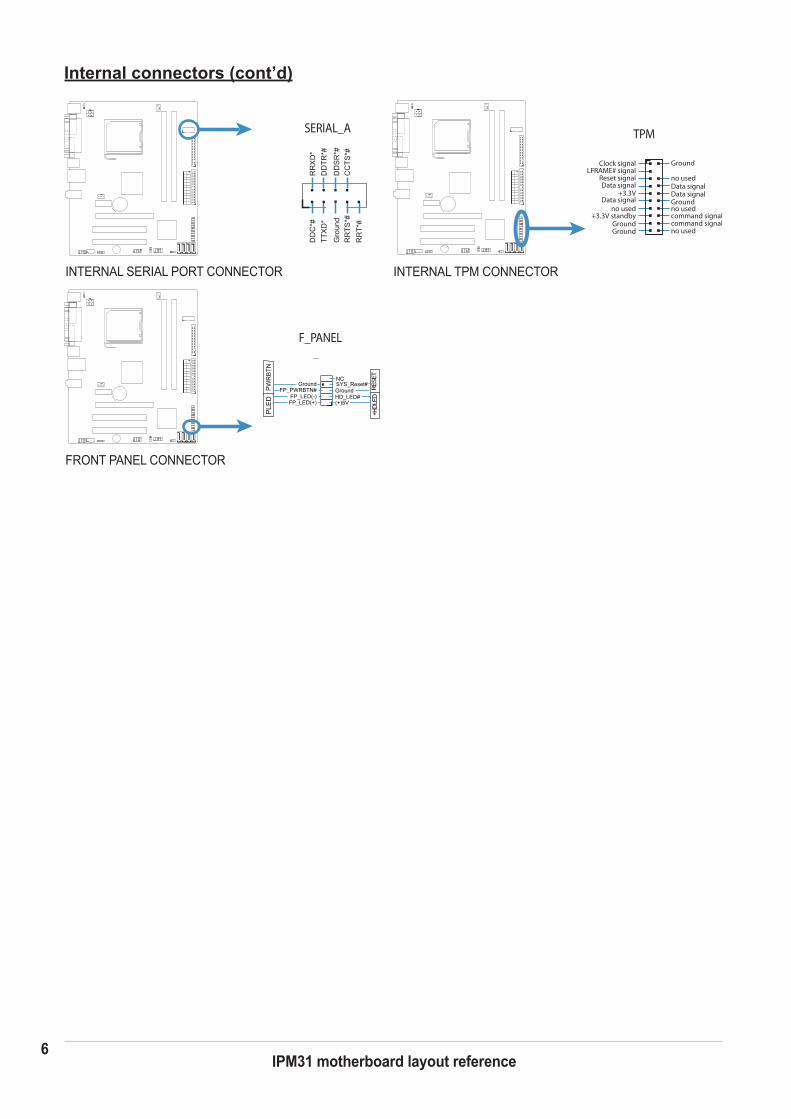
Internal connectors (cont’d)
TPM
Clock signal Ground
Ground
GroundGround
Reset signalData signal Data signal
Data signalData signal
+3.3V
+3.3V standbyno used
no used
no used
no used
LFRAME# signal
command signalcommand signal
INTERNAL TPM CONNECTOR
TPM
INTERNAL SERIAL PORT CONNECTORC
OM
DD
C*#
TTX
D*
Gro
und
RR
TS*#
RR
XD
*D
DTR
*#
DD
SR
*#C
CTS
*#R
RT*
#
SERIAL_A
FRONT PANEL CONNECTOR
F_PANEL
GroundGround
(+)5VHD_LED#
+HDL
EDRE
SET
FP_LED(+)FP_LED(-)
FP_PWRBTN#SYS_Reset#NC
PW
RB
TNP
LED
F_PANEL