,= la-12633-ms ,= uc-700 iswwfi:nmwbcr 7993
TRANSCRIPT

,=
LA-12633-MS
DirectionalMemurementsfor Sourcesof FissionNeutrons
RogerC. ByrdGeorgeF. Auchmpaz@IWilkm C. Feldman
LosAlamosNATIONAL LABORATORY
,=UC-700
Iswwfi:Nmwbcr 7993,—
~um4+
LosAlamos,NewMexico87545.,3; ,,a ;* p#j ,.#J!-..’-’-b ”f-:“
. .
I1=
I
1=
,=
1=
,– .
1= .:.>..>:.1. . . . ,.:
- .,. ..,=
Ii
I,=. .
, ...
,=

1—,—
,=
i=
;=
I
DIRECTIONAL MEASUREMENTSFOR SOURCES 01’ FISSIOh’ NEUTRONS
t)j”
Roger C. Uyrd, George F. AIIc.lI;iIIIj);iIIglI, and Willianl (,’. Fddlnan
ABSTRACT
Although penetrating neutron and gamma-ray emis-sions arguably provide the most effective signals for lo-cating sources of nuclear radiation, their relatively lowfluxes make searching for radioactive materials a te-dious process. E~”en assuming lightly shielded sourcesand detectors with large areas and high efficiencies, es-timated counting times can exceed several minutes forsource separations greater than ten meters. Becausedetermining the source position requires measurementsat severai locations, each with its own background, thesearch procedure can be lengthy and difficult to auto-mate. Although directional measurements can be help-ful, conventional collimation reduces count rates andincreases the detector size and weight prohibitively, es-pecially for neutron instruments.
We describe an alternative approach for locating ra-diation sources that is based on the concept of a po-larized radiation field. In this model, the presence of asource adds a directional component to the randomlyoriented background radiation. The net direction of thelocal field indicates the source angle, and the magni-tude provides an estimate of the distance to the source.The search detector is therefore seen as a device thatresponds to this polarized radiation field. Our pro-posed instrument simply substitutes segmented detec-tors for conventional single-element ones, so it requireslittle or no collimating material or additional weight.Attenuation across the detector creates differences inthe count rates for opposite segments, whose ratios canbe used to calculate the orthogonal components of thepolarization vector. Although this approach is appli-cable to different types of radiation and detectors, inthis report we demonstrate its use for sources of fis-sion neutrons by using a prototype fast-neutron detec-tor, which also provides background-corrected energyspectra for the incident neutrons. Computer simula-tions of possible search procedures indicate that thedirectional capability should significantly improve theperformance of searches for nuclear sources.
I,=
,—
1=
1=
1==
:—
I1=
1=
1=
I,=
1

1. INTRODUCTION
Shielding for Radioactive Materiiils. ljw;[ljs(. J;!;l]l} lltlcl(I;Irwe;ipoflsarc ha.sed ont t](’r;i(iio;lcti \’(1II);tt(’ri;~lIllIll(Jlli1]II], ~Jll(’ ()f t II(’ (“](l;l l’OS1 Sl~Il ;1t 11l’OS f(jr t)wir tletcrt.ion is thep(’11(’triiti!lgI“il(liill ill]! 01”X-l”;l)”s. ~,illllIll;l I’i!)’s. aI:(l ll($ll!l”O1lS ftlat t]l~}” ~!lrlit. }Iigtl- density
I]lat(’I”ials .iii(”ll :Is 141:I(; (“AII I)(I 11>~’ilII) slIi Pl(l [II(I tuo (~1(’(”tI”OI[i:igIl($:i( rad]at. ioust although
large th;(kIlw(’s IIIa~’ }J(OII WVI(’(1 for p;alII IIIiI I.d})s ;I1 Ilixtl (’Ilorgi(:s. Shidding for fissionn(Iut rolls. of) t lt(IollI(Ir l);!II(I. r(uiuiru 1)111fi.v1)111.rd;it i\“ol}’ligltt w’(}ighl.hj’(lrog(:nous materialsSIIClI as pl;isti(” or w’:it (’r. l:fl;vf~~t’ sllif4(li Jlg Ii)r t)f)l. h liolltro]ls aJI(l ganlma rays mustt Il(jrofor(t”I)(I I;Ir~(’ ;III(1ftl;tssi1(I. wJ ;I I.;(I!i-hlli($l11(1(1stliI)])iIIg (“olltai ner would he suspicious
I)(v;tl]s(’ (Jf its slt(vr siz( ;III(I w(’i~lll. .’; :If141;ir sfI;ir(”l I twlj IIi({il:v, IIs IIally ftxploit this difficultyI)yIIIilizillg \)(JtIi lJ?I)(I>(,!’(1(’1II(IIJrs.
Directional Radiation Detectors. 1“01”])fJ1”t;tt)]f’ i Iistrlllllf!llts , shid(li IIg constraints;11so afliwt t Ii(’ (1(‘si~li I)t”(“01fiIII;1tI)rs f“()r (!($!~’rlIIi1[iIlg Itl~’}(J(”iIt i(Jll of a l“ii(l i at ion SOU rec.])(TiiIIsfI IIlo(]est ;III IIJII !Ith of”I(;i(i (;:]1 jjro~i(l( sig]lifi(;l[lt ;11t(’tlu;ltioll at 11)os1vmrgiw, field-ing a (1iIXIC!iolla! :;I IIIII!h-Id}’ 11(11.IIrt(jr j)(NIh Ii1t I(I (!ifiir IIII}“. l;ff~wti~v cdli[]lation for fastI)(IIIt rI)l Isis III IICII lIIf)r(I (.11111t)(’!w)lil~’. 5(I 114111t I“()!I d~Il ~111(Jrs ;I rfI usu all}” (I(!ployo(lwithout di-ror[ i(j]liili f}. I’or ]OIIK- r; I IIg(I S(I;I r(lI( Is. t tlo I; I rgt’ siz~’ of a!Ij (l(It(:ctor Il)akes (?ffect,i\’~1shielding
il]lpossil)le. ‘1’hIIs. it ifoul(] })(I useful t(] dP\oloI) lwlllliqll~h for det~’rIrliI1illgt ho directionof ill(.i(l(’nt r;l(liat ion t Il;it w’(Jl]ld I)(I (Illivt iI’(I(11.(sJIwi1II Il]ls}lifd(l(.vld(’twt.ors;, particularl~’t h(JS(’ 11S(’(! f(Jl” f’;lSt 11(’11t 1“011S.
Related Work. ,\ rw(’llf l“(’])fJI”t1 (Iis(.l]ss(js(.OIJIplltcr sirllulatiolls of dirwtiona]ity forslli(!l(l(vland 11[1s11if’l(lfvl f“;ist-11(’11t l“(JII (1(’1($(’t(JI’S. ‘[”11(’prcsf*rIl pap(’r cotltinu~’s this stud}’ t)yusing ;t(”tUill II If’;Isll rf’lllf’flts I () f’sa ]]li 11(’sc)lllf$ I)rar( ica I applic;it iotls. ‘1’tl~’ drt oct.or enlploycdis ;) llotv’1itlst rllll]~’lltori:i IIiillj” df’~”f’lo]w(l as il Hellt r(Jll spwt rolll~’t~’rfor space applications.zIt has ii]sf) twc)ll Usf}(] fi]r StIl(j}”iligll~.”lltl“oI!-iIldll(”~$dfissiol! iIl ~’llriched Ill”allium.:jfw”countin\\”illIlc;i(ls oII silo- I);ls(xf]Ilissi 1(’s. 1 fa II d for III(I;ts11rillg f;!r-field f!l]ses frf)lll ii nuclear reactor. ’‘1’11(1IIlc’as(j]”(’n)(’titsarr part of a SIIIdJ’ of’ tissioll spwtra fiJr realistic mockups of nuclearW’f!iipol)S. .I\ (:OIll[Jiilli(JH ])ilj)d; (I(%(”rihost II(I(](!t(}(”tor(“;ilii)r;ltion aII(] sp(!(”t ra] ana]ysis. anda cliissifivd r(*port wiII discuss specific f(’;itIIrw (Jf t IJVlIIfJ(. iiu p sp(:(”t ra. ,\lt hough the presentIllciisur(jl]](~lltswore !Iot (J1’i~i tI;I 11}?i tlt PtI(l O(l 10 (Iolllf)llst r;i f P t IIP d~’t~Ictor-s (Ii rf’ct if)nid i ty. they
nc~”(:rt lI(Il(Iss p rr)l?i (1(1;I II f’s t ensi ve ;In(] rwl 1ist i r sot of Imt c;Is(+.
Contents. %w:tio[l Y j)r(vwllts ;I I)ri(*fsut]]lll;ir! (Jf t II(I (Jl)oritl ill~ l)rillcij)lf’s of tho uniqu?dct(!(:tor used in 1110prcs(’tlt work, wllicll is (1(’scri1)()(1lll(jl”~’fllll}”i111{($fs. 2 and (j. SW-tion ;~explains t ho ((.)n(q)ts of a dire(”tio]l;ll rii(l ial iol! fifjl(l d II(I its (ii ;irii(”tf:rizati(~n using
a mu] tielemcnt (l(’t.(’(”lI)r. %wtioll .i prcse]lts t 11(!I]];itII(IIII;IIi(;ll I“i)rlll;tlisll]for extract ing thedirectional inforll];il iolt frolfl the InP;~sII!”e(l(“olltlt riit W. aII(l i! UIIIIiiirls t hv i)l]lk of the mea-SIIrw]lrnt.s t lI;it (IPIII(JIIS1 ra to tllc t)asir t(1(.11IIi(lllo. S($(”ti(JI] .7J1]S(,S \!OIlt (’ ( ‘ari(J sirnu]~tiorls
to f’xploro t lw a(lt”;;tlt ag(I~ t lIii I t II(!!Iiro(”tiotl;l] (.;ip;il)ilit}”(;i]l proj”id(l itl h}’pothctica! searchsco]iarios. %?(”tio]l (j (I(w”riI)(Is tweoa(l([iIio]l;lI ;i])])1ic;it i(JIIS of” 5P~!II(IlIl (d li(!u t roll detectors.
on(> vxt (lII(]S t ]1(1(]i r($(’t if)lla] ;I !i;i]~”sis t f) t ]IV f%t. iltla t.ioft of sol]r(”()s(q);;riitif)ll disl ances. andttlc (JtlI(Jr(Iis(. uss(}sil I (1(11IIi(]l](’ l)rol)(Js(I(l iII I{(’f. 1 for oi)tiii]li Ilg hiicligrou nd correct ions to111(’asured cnc:”gj. s[)~v:tr;]. S(*ction 7511111IllilI’iZWtII(’mutts fron] t 11~’~’rttir(~report.
2. DETECTOR OPERATION
Proton Recoil Scintillators. Ill organic scintill;itioll detwtors. Iieutrons tltai +catterfrom protons in t II(Ipl;ist ic produw ])rr)to]l-l”~’(oi)ilW)~Irg)-;ind dvtect a blc Iight out put. \40stneutrons scatter onl.v ;i few ti nlcs ;Lnd t }IVIIesciipP. so t }ICJ-lose ()]11}”a fraction of thei Ioriginal vncrgj.. S(JI II(’. lIOMWVI” . S(”;11t (’1”t ]11“01],!!11];I ]“~(s(’]1(111~]1;1Ilg] f’5 1() df’~)OSi 1 ‘Ssf’ ]1T i al 1}”
!=
;=
,=
(=
.—
i=
,—
I!=1
.
2

r,=all th(~ir (IllergJ’ il] II](IIirst f(,w ( ollisiolls. ;I II (I I II(Ij’ I)(v”olII(‘ 1r;!JJIJ{XIilt t II(Isci]]t i1Iat or. flc’-ca usc of sat uratiu]l itl tll(’ sci t;till;itor’s (111(’rq}-l()-Iiglll co[ilwrsio]i ;il cn(~rgies twlmv 0..5 NleV(Sw I/f I”. 6). ful”tll(,l”(ollisloIls” (lo III)( l)ro\ i(l(t il(l(litilJIl;ll bigna!b. ‘1’}1115. allllost ;111 t 11($(111-erg}’ cf(lposit (1(1l):; :1 1r;iIjl)(’(111(’1]t r(Ill is (v)IIf$(1(vI iII1() ;I si IIgl (I p rolIl I)t ]) rot 011-rvcoi I p Ii] sC.whose at]]!jlit u(I(*is (Iir(~(”tl~rc’lat(’(I [(~t It(’ il:(i (l(I!iI IICUt loo!;~’llerg}’.[“!lf(Jlt.(lll;lt(’1~.writ.])arotll,(’ntiollal scilll iIIiltol” t Iicre is 110\\’;iJ t, J (list iIlguish !)(I1\\’(w[lsign als fr~)lll trapped and(,s(”;ijIiII !, II(*II t rolls. s( ) il (.ollti lIuolis (1i St ri 1)1]t i ()! I 01’ ]) rot 011-rocoi 1 (Ill(trgi(vi is ol)t ai !Iml. ‘1’lle
‘“J”W) , ‘ ‘Ct I’ll 111~Jf”111(’origi Ilal 11(?11t I’(JIIS ( ii II 1)(’ I“(’(”(J\’(’l’l’(!(Ml]j” 1)}’ II 11f(J](] iIlg tl)is complex(.:i ~r ,.: ‘ it ,VI.
1=
Multiekwnt Detector Direct. !onalit,v, ‘l”lI!’\(’(”oll(lIIr]l]sl]al Ii’iil Ill’f’ Oi” t.h(’ cfetwtori:5 the OJ:II II1(JSI i III iJI, ! ! it f; t !iJr I II(I l)r(’wIIIl lit II];. ,1> sllf)url i rl rig. 2.1. 1lif’ inst rulll(’rit IIeadronsist 5 of f(Jllr t)(~rf )11.i( ); I(tf I(l ,s(iIltill;!1()r rt)(I> \’,it!! ])llot01111111 i]Jli(’rt ub(’s al each cILd. ‘1’lIcIfour sid(’- I)y-side sci III ill;, I or (Jl(’l[liJnt:. itr(’ i III (111(1(1(1to itl(li(;it(t t II( (Iir~’(t.i(~llof the incidentneutron fius. III t h(’ flrigi;1;(!(l~+.cri l~tio]l.~ 1]1is ;j~lgll];,r (;,p;l I)i]iI \ U“(15d(’lllonst rated oII!J
far ch~rgwi part icl~- I:1ll(~llsgt’11(’!.;lt(’(1}J~,(.osltli(.-r;l~.illt (Iracl i(Jll~wit 11t II(’~pacec raft j. Asdevelr~[je(f in ]{(’f. 1. t ]IJ’(]ir(’(tioll;l] irlfi)r]rl;,li[jlt (;lrt ])(I Irs(’(f ill tu,, (Jt]l(~rw’a:,s, First.(Iiflert’llccs ir) s(jli(l illl<l~ ;Iri(l at1(111uati(jll it(“ru.sst lt(I (1(11~1(”1(jr (“r(~;~l~’(1if~elwllc(’stwtw.eenthe COUJJL rat(w for (Iifli)rollt seg!I]eIIts. \\.lti(“IIc;iII }WIIWKI 1f) r;i I ( II I;il(I IIN (Iir(vt ifIn of’theincident flux. “I_ll(~c;iI(lllat iomssu<gmt t ttat t lio syst (jr~t;it i( ;lII:l,’ ;t((l] rac~. fi~ra n ullshieldeddetector sh(Jll]d prf JtJ;IiJ]} })(1 w’it]lill 10°. S(!(”oll(l. f(Jr S0111.(”(%[)lii(C(l ill fI’O1lt of (JI)C ~~ir Of
rods (a+ in t IIis Ox])(’rir]IPIII). t hc op]msi tc p;~ir c;iII IJPI]s(I(It () P-TiIf]at(.’;t (l>rrw”ti(~ltfor roombackgrou IIdS. L.Il(l(*r.~IIlll~’(iIcllrr)s[:illcc5. SII(”]I ii c(!r”r(}ctiorl t j! II j)rr)\. i(i(. ii II u ncol Ii n]ated
detector wi[h all ~’ssfrlti:,ll) onwsi(l(*(l rcs~JOII.\~I.
Discussion. ‘1II i: I)riof (l(+(ri]Jl io]l of t lii i[lst rur!le!ll IIWI ill t lI~J \)r(wIIIt rlw~sur(’mentshas stressed t !Ie tw(, !I;it ur(+ 111(.wIir:ll)ort ;I],l for III(Jl)r(IS(Itlt;I)I;,I}.S,,...I’irsl . T]Ios(;it ter-and-capture select ion r(‘s1ri(“ts I II(Ir(’sl)(JnsO()11[) t (J II f.>11t rolls. i,;: j>” ;1I orl($rgi(+ ii t)()\”P 0..5 IIC1:.and on Ij. t how IIIa I II(,I)(),~i( a II t hoir rnerg}” jII t II(I(1(.I~wt ():. SI (Y)ll(i. t tit) ikl(lr-(?]~nl(?ll[~eg-mentat ion pro~-i(l(’>XJIIIf* i II f’orIllat ion A1)1)11t 1II(I (1i rl’ct ioII I )f 1II(I i II (i ( I(JII 1 f]t]x. Prc\.iollsl\..t,his infornlatioll II;LSr(!(($it~~vfonl~. a (.I1r~(jr~ (~x;inlil);iliorl 1,) rll~’iirl<of silt)ple conlputersimulations 1 or n]o;isIIr(.’]r)c]lts w.it h clliirgl’iI ]);irIicl[I>.Z 1{IIi(“II1)(111a~(~icr:; different 1~.fromtne neutrons and gall] IIIit ra~.s of inrercst for i;l(liiiti(J]i .-~>ar-(11a[)l)] icat ions. k’urt]lermore.the previous anal)’sis ‘ f“ocu>rdon drt~’rn]irlirl~ 011l}. S(III I(V (Iir~v-tio]]s ;iJId background cor-rections. Yeither of tltww applicatio]ls is ;I ((jrltr;ll f;i(l UPiII t II(I pr(!s(:II[ cxperinmlt. whichused a low-scattering cwt.ironmcltt (so t Ill}I);i(”kgr(jij:td ((~rrc’(”tiulls are small ) an(l sourcesplaced directly ili [rent of the detector (so 1.!I(Iill(i:lerlt ;JIIglcs are known). Instead, thefollowing analyses rflt(’al t}lat al] iInI)(Jrt;lrll :t[li;l]lt :IX(~(JI”t I!( (lir(vt iolial illforltlat ion lies
1=
,=
,=
I1=
1-,—
,=
I1=
L

+.
,:. . !
PHOTOMULTIPLIERTUBE . . \WITHBLEEDERSTRING ,.
AND PREAMPLIFIER “:’ ?2s /
YgHV POWER SUPPLY
3. POLARIZED 1{ .ADIATION FIELDS
rl—/=
,=
,=II,=
1
I;=II1=
~=
1=II,=
I
I!=
I
,=
,—
;=
,
,.
:=
\
,=
,—/—
i=
i-,–
I1=
:=
L —
I

r~.(> ●
[1 r> ,1●
o ● . ..........,,.,,....●.......... .)
. . . . .,.
~. “b*..., :,c) . .. . . . ●
●● Q ..’” c, ●
...0 ..
CL.C .,””,.., ,, ●c ... !1 ,, ... . C/
+
1—r—
● ✎✎✎” ~ ?,.,,.”
,..●
., ..””
..,” G?: ● O:Wli o c)
(2
● ‘da,, (’ ,,,?,(.
,-; (;●
.. I. ... .r)
●.., >
r .. m,
.~● 9
0●
orJ
●
●
# ●
✎✌ ‘(J●
J,., cl‘,
L=
[.
9o* .... g :, o c’ v’”
b o ●..., ...,,.... <J● ●
3 .. ● ●
● ... “bG~ ●,.s”’”””. 8
3 ... .. 0s~ G
%, ..., ~,● ~ c o? ,“””*,<‘...., w,..,” 5mSepat-atj& ●
● . . . . . . . ...C...r4c“ ..... .. ...... .... ... ,;
●
(a) 3
● .* ●
● * ● .0 ●●
● a ● 9●% ● . s
● *● ; ● .0
9. 9 ● ●●
/= ,,
I “’—,~–b
I1=
[..● ● ☛ 9
●● ☛● ● 9
w● * ● 9
● %e.me ●°
●
., e ●
●●
,0 .●
●
●●
●.e ● ●.* r.;,,....q.2,
“,;.$ ,i.,..... ,.,.. ,.),—
[= .“”—,.,,[““,.
~..’, :
●
●
●
●✚
●●
●
●
● ☛ ● O●
●
●
● ✝●
●
●
●
● ●O ● ●● @e* ●
● ●● a
b’ 9.. ●
%. ●● 0
● ● . ●: ● ---- Sm Sepantkj~ .● ●
● * ●●9 ●
i—r‘,=.1“
(b) ●
Fig. J. 1:,,1~. Simulation of detector countirlg in a radiation fie]d producedby a l/r2 ..ourcc flux and a uniforlrl Lackgroulld. in the upper panel (part a),the OpCIIcirc]e5 are source count5; the closed circ]e5 are background count$.In the lower panel (part b), no distinction is made between source and back-gmrnd ~(]lltlts.
.5

(1(11(1(1illg ;t sigllili(”;!tll (oII;iJIg(Ii II COIIIII r;tt.(t II II I(ISS 1II(I M)II rco is Il(!ar at hiind. ‘1’his difficulty
is f’uII lIPr ~1111l~tlasiz~vi1).vFig. 3.1 b. v.tlir i! (1I(,]J~ t )1~1;irt ifici;il (Iisti:l(:tioll between countsf“l”olllt tl(’ S(Jll I’(”f’ :111(1 t ]If’ h;l(’k~I”ollIlf] . OII]J” ;If \’f’l”J”(“](JSt’ ;lpprodChf2> iS t}l(! VariatiOn iIl
(“(J!llli I“iit(’(“](’ilI_])”l)t)>~’t”t’;lll]~’.
Directional Radiation Fields. IIJsIII;l(Iof” f“(](llsillgsol(d~’OH varialio[ls in countrat (I. Fig. 3.2a II SfI~ ! ti~’ ~ArIIfI sitlllll;i! io~l t~)ill IISI r;tt I, 1Ilf’ ciJIIcfIpt of ii direct iorlal radiation
fi($](l. ‘]’11(1S()]i(j IiIl(, $(tglll(>jl(~ r;l(li;~t{t f“l”ol:l fllll SO1][”(”($ I()(”;iti()]lt L]l(? d(ltt(d sf?~ltlf?rits hiiv(?
ra]I(l(JIIil) Cl I(APII (Iir(v”lions. ~\g;,ill. t ]1,1,$’//) j;it io of .7):I ;It tll~’.5-III sf’pariit ion is apparent.
III this (“;isfI. howwt(tr. 1}1(’ (“ollli li!l; i~if)ll of >[)111”(”1’;111(1]J;l(:@WUIl(! idS(J ~ffW’tS th? av~r~g(?
dil”(’(”tioll (If 111(1]()(’;II 1111x. IIOf ,jllsl 1]111l’;!l”i;lli(~ll ill (’(JuIIt rdtf’ fr(J1ll ])oillt tf) pOi Ilt. Thisass(Irt i(~]l is su piMJrt (xl 1).v Fig. 3. 2b. U“IIi CII a~;ii II (1IX)ps I II(I d isti Ilct ifJll bf’tl~ww counts fromtil(>S(JI; 1“[”(’iill(] t);l(”k~l”flll 11(]. I“or II I~O;ISIIr(JIII~IIIt: 1“:1r i“r(~III t 11(1sourcv. t hv dirwtions of the
(](11($(’t(}(] ~);il”! i(’]($!i ;1I“(*1“;11/(](11111 ii>, 1Ill! 5(JI]I’(”(* is ;i]J\)I”(J;l(”]l(’(!. t ]1(’ fra(’ti(JIlOf~arti~k$ with a(](l[illit(!ori(tllt;ili(ljl i!l(”r(l;[s(% to 10(J(l. III I(~rIII> (Ii” !JIJ];ll”iZ;itioIl obS(?r\’~b](%. OIIC1referS to the
riiifi;lt ioil fields for li~’iir :111(1 far SOII IC(IS ;Ls tl;it’iIIKj)Idarizati(Jn nlagnitudes tbat approach
1.() illld ().0. 1“~’S]JWti~”l:l~. ‘I”)lis iIlt*’!l)rf*t;itioti lo;ids ttJ I w(J (vll(lusiurls: ( 1) ‘[’he net direction
Of t ]1(! IOCal p(J]~l”i Z;l t i(lll \“(’(’l(Jr ill(!i C;It W f.h~’ 1110S1 !i k~’1}”dlI”W1i(JIl fOr the ra(fiat iOIl SOUrCe,
iiII (1 ( 2 ) t )Iv III itgII i t IJ(I{I 1) (Jf” 1ho j)fdiiri zal ion iII;.IYI;IWISfroln ().0 to 1.0 as the srJurce isap[)rO;lC]lP(!. ‘]”]IIIS. ;f ll(lllZ~’I”f)]Kd;ll’iXali(Jll 111~’;l>ll1“(’111~’111[Ila}”])r(J\”iCf(!a S~’llSiti\’eindiCatOrof a dir(wtiorla! riid i;tt i(JII fi(’l(! a II(I 11/:rl(”(*;I I(J(”;I1izr’I1 rwut rori sou rec.
Basic Polarization Observable. “I”)”i)iriill)”.ll(mv’t.(~r.t ]10po]arizatiorl of a radiationfifd(i cannot be obs(~rt”wl(Iir(’ctl}’.but it rllust IW(1(1(111(:0(1l“r(J;t]differerl(ws between the countrat(~s i[I a [Iiuj! .,I(.[11(~[1I (I(?tocti(]ri s~.st(.)[11.IJI o II r c;i5f I. wv: ud t ltc f(}ur- rod instrument ofl’ig. 2.1 \\”itII its lfJIIg ,~.sis \xIrtical . SO t~lat ~’;l(”]l1’()(] f;l(”d ii dif]f!r(!llt di rPCtiO[l. ]n theforrrla]isrll of’polariz;it ioli olJs~w\.at)lv:>.t 11(’s($llsiti \.it}” of ;1dctwtfJr tf) the ]MJ]UiZatiOIl P ofa rad iat iorl fi(~ld is r~’f(’rr(d !u as its arl al}. zirlg p(n’:(’r .1. v;}licll Jarifjs frorll ().0 (no response)to 1.fJ (p(’rff’ct res\]O1is(”). II! t tlis friilll(n~wrk. a Jll~:;l~lll~~lll(*llt.s polarizatiori characteristicscf(:perld orl hot h t lift fi,.l(i ~rj(l t]l(, (](:t(,(.t or. w]ji(”]l ]fI;I(]s t(J a product referred to as the
as}’]11rrl(’tr~. // = /).l. Jr is this c(Jurll-rat(’ il~)rl] III(II r}” t lI;tt forlrls the ccr)tral polarizationqu ilrlt i t}” <Jl)tai riwl i II I II(I lII(Iasu r(’lllmlf 5,
Summary. “l”l[isswti(J1l IIiis pro\id(’(1 ;i sir]l])l~jillilstrati(~li of tlie effect on searchljelia\.ior of b;i(”kgrullrid c(Jrltrit~utir~rls. of t II(IiII ~(.r>f,-s(llj;ir(:falluff iri signal flux. and ofco[l[ltirlg st;ttisti(.s. \\.{111.~\.cusv(l t ]1(1 rii(li;il (:ll;ir;i(ff,ri~l i(s of tlic ~’rliissicmsfrom a point
sourcf? t~J ir]t r(Jdil (’~* 1lif I ((~rl(x:j)ts(~f;i polariz~’(1 r;:(li ;I1if)rl firld arid a directional radiationdetector. ‘l-)lis ;ipp!fJ;iclI lIiis r~mllll Id itl art ;ipljli(;tl iotl (Jf d~’t(:ctor directionalit~? not an-ticipat~ecf in t Ii(’ i(l(:l!iz(v! sirnl]]alio]ls of Rvf. 1. 1“01s~JIIrcw ;it l[lodcrat(~separations (upto ii few r]i(!ters j. rll(Jsl of t II(I neut mri flus i > i ]I(i(ll’111 011 t II(I (!oI wtor frCJ[ll d Ij;irt irulardirwctiori, wliic!l :)r()(111(~’sii (Ivfirlil(’ (liff~’r~’rl(~’11~’1‘:.~’~111111~(IJI]I]I r;it (.ISf(~r 1!Iv differx?lliel(’rllorlts. ,\t liirg(’r .S~*l);il”;il.i(~rls.]lfJV.”~’J”f’r.t 1110f~i]lxt ..I) III(VI (0111 ril)litif)ri dwreasm as 1/rz.
iirl d r[m.lt cf t }If’ (1(s1(I(”!~Id rl(III 1rolls ti;i\VI >(“;I1f (’r~,(I f’rolrl t 110air. v.iil]s. or floor. I“lius. thepolariz;it iol. of I II(I r;i(li;!t iorl fi~’1{1pro~i(l~’~:1JII~I;i>III~III~~IItof [II(!sigrial-[o-l)ackgrou]ld ra-tio aII(l }IcII(.(1iirl (+.1irri;it(’ (Jf 1II(I]Iwrll(w of t tlf: r;idiat iori sourw. ‘l-he cwtral result isthf’ equ;itioil // = /’,1. w“lii(.t[cr~nrl(t(.tstlw fi(~l(l;ill(l d(.’tm.t(Jr jJiiriirrl(~ters F’ and ~ to anleiisurable courit -r;il c iis}rrllrlct r}. R. \\:e }i;iw ;IINJ;irr~i”f!dat two significant predictionstliat caIi be t{!st(v] agai mt expcrir;im, :al res IIlts: ( 1) I~iv polarizatirm directio]i indicatesthe source angle. aIid (2) the pO]iiriZati(J!lJ!l;lxJlilIi(]~I (]opeIids wi t]ie signal-to-backgroundcharacteristics of tli~’ r;idia~ion fi~~ld.
,=
I
l—
T1-y1=
,=
I
,.
i=
1=
(j

—,
1’,.,/,
,L:—:
.
(a)
/ .......//“””””””””””-......,/// ../
\ \’ y\
L \ ;,,). “v-.
,—
,=
,—.—
,=
;=
,=
I1=I
(b)
Fig.3.2a,b. Simulationofa directionalradiationfieldproducedbya l/r2source flux and a uniform background. In the upper panel (part a), the solidlines indicate the directions of source particles the dotted lines indicate arandom background. In the lower panel (part b), no distinction is madebetween source and background particles.
1=,,
.,!
,
,=
!=’1-,–
1=
.;
{,=
,=
I

4. POLARIZATION MEASUREMENTS
Overview. ‘1’tliss(x”ti(JII I)egilts h}”wl;il i]lg 1II(I (OII(”(Ipt u;Il fr)ur-elc’lli(il]tpolarizationL=
det wtor of t II(Ipr(wious s(v’tiot~ to t II(’;tct II ;II itlsl IIIIII(IIit US(I(Iin t II(Jlllcasuretnents. Af- [t(tl, (l(t~,plo])iIIg ;1Ill;ltJI(IIII;ttj(.;l]forl]l;ilistll });Is(I(I011st ;ind;ir(] [)01;1riz:itioll allitlJ’SQS,W’euse ~=
esa IIIpl(wfroth t tlo III(I;iSIIr(~lll(wtsI() 1(Ist 1II(Ipr(Idicliotls III;I(Ic iII t hc pr(!~’ious section con- 1(KIrII.iIIg t II(I(Ii1“(1(”1ion ;ItId ItI:igIIit 1](1(*of t II(* liJ(I:isIIrfItl jJol;I riza ( iof) \’(’(”tor. Most of theIl)(}~SII 1”O1ll(i’ltS \\’(il”(>Ill:l(!(l for (Iistril)utP(1sollr(o”s”I()(;lt(v] ;I1 la I.iol]s(listaI~cesin front of
~=
1}1(’ (I(?!(’(”tol”. ;111ill il !)ollt t tl(’ Sillll(’ jill~l(’. ‘1’hf~ (.iil(oII]at(I(l (Iir(v”t ion (herefore seri’es mainlyas it (wt)sist(’11(~” (.11(’(ok.alt IIOIIg}I t II(I tll;ignit 11(1(’of III(Ipolariz;ition should decrease as the
1–=
S011rre $ipl)~l’ilt iotl i ll(”r(.t;Is(v+.[
Experimental Configuration.~=
‘1’11(~!]l(I;tsl]l(IIIl(Illtsuvr~’ll);idvwith the sources placedroughlj. ill fro!lt of IIIP(lotwoIora( r(vor(l(’(1 :(Iparal ions of .51 1Ifio (“III!(“~ntertc center). ~=‘l’()I’C’(IU(”(’t }1(’ (“Ollllt I’il{(’ fl”olll~illlllllii 1“il}”S. t II(I (lIIt (’(t I )r J{’;isSIIrr(}IIIId(Idt))’iit least 0.95 cmof l(>a(ls]lc(*t011;III si(los. Figure 4.1 c(J1)ltwls OUI” (“(JII(”(~ptIlal p(diif”iz;ition ana]y’zer W’ith L.t II(’phj”si(”aifollr-ro(l”i!lstrIIIIIeIIt sll(nt.rlill I’ig. 2.1. sll(n~?itlgt II(S Ilutlllwring of the four rods,t II(’aIIgl(I(xx)rdina [(’s.;111d t11(’rigllt /loft / l“rolI t / l)ii(”k (1i r(l(”t iofls. ‘1’IIQ att(~nuation throughth(?(j(’t(’(”l(~riiIIddi[li~r(.~]1(”(%i]] s(did iill~](’ pro(]II((” a uI1i(lu(~ ]J;lt t(IrII of cwunl-riit(’ ratios. At [-
\—the Sou1“(”(’j)ositwll Sll(m’11.]{(J(]2 w“oII]dhai’c th($ ]Iig]l(%t r:ito. f(dhm”cdhj” ]{ods ], 4, and3, r(~:+pwti,“(11}’.:\s t11(’W1l IW’ ~llgl(’ d ill(”r(’ils[’s1(N”;I1”(I1.5°.
(t hv count-rate ratio between L—
Ro(ls 1 and 4 decr(s;is(Isto l: 1. while t h:tt b(’tw(vwI{(K!s1 aIId 3 irlcreases to its maximumvalue. w’hichis almIIt .1:1 for l.he geotlwtr}?:111(1lIIaleriii]s of our particular detector.
................................... .......... ............... ...............................................
+900DEfECTOR
SOURCE
j 180°
@@///2..,.:.:. .——
00—-.—.—
31r?~,~/*&-+i- O.
-90” “aR.
BACK FRONT
Fig. 4.1. Detector and source geometries. with angle coordinates shown fromabove. Rods 1 and 2 are on the front side of the detector and face the source;Rods 3 and 4 are on the rear side. A source angle of zero degrees is straightahead. The inset shows a detector-centered coordinate system used in theasymmet r}’ calculations.

Directional Algebra. ‘1’11(’fortna] (Iil”(’(”tiollill f“ill(”lll;ltiollS ;II’{’ >Ilrljrisillgly sinlplc.Three observable arc obtaimd: ( 1j thr tiIIg,l{I.;i\’(II:Ig~I(lII(IUII(MIIIIIX;II (II(Id(d (’ct.orl(Kat h.(2) thenmgnitude of the local pohitiztitk~~~nd (3) lhvdivwlkHl(Jlhr hwalpolarization.Alternatively, this illfol.l]l:itio]l(”i~!ll)t”\’i(!l{(’(l:isiis(”;ll~*ttl~.’litrollflux;lllda t’(!(:torll(’(it.lollpolarization, which ($Orr(ISpOIld to (tl(’ sill gl($-ro(l (“011111.I’ill!’ :Iti(l tlIf I fllultiro(i (.ollrlt-r;itf?asynlnletr~’. III Ref. 1, the cal(”ulit[iuns us(u[ dill’(tr(’~1(”~’sIMw”lvtl th(’ C(JIIIII ralvs for oppositerods; the current software emphasizes th(’ r;]tios INJIR’IIVIIth(w’ cmIIt rat(’s. ‘!’IIClocalaverage flux 4 and its ~rilct.iotlal error (o = (1+/0 ;lr(II)i)t;lill(’(1froIII t Iw four indikeidual-fodyields and errors ~i + d, as
+ = ((b, + $52+ f/):\+ (;).,)/1
The measurable (Iirectiol)al pariil]wt(~ris IIIP iIS}’IIIIII(~IrJ”/{ ;III(Ifractional (~rror (}{. I“’orsimplicity, the (lN(’(.toraxes ;Ux’~Jri(’lllwi(Iiilgoll;llije t IIrougll t II(*1 i ;{!1(12 3 (kt(!c;ol”1“0(1s.and the source angl(~d is shiftml by ~/,i (I ~}”) to ;:ligll t IIC;lxis with Z(IIW(logrc(Isfor sourcesdirectly irl front of Rods 1 aII(! 2 (SW Fig. .1.1). olIr :I])]jrIJaclI1I“(I;I1st Iv count-rate ratiosas the components ( //l.l, /?23) of a \wt{)r W“IIWIlCIIRtII aII(l (IirvctbII arc R aIId0. Thecalculations proceed as fdhvs:
n = #j jo.l. ;j = (:1:/(”):$
fil,~ = (n – 1)/((i + I ). //~:\ = (,j – 1)/( .j + 1)
112= ( 1(;.,+ Ii::,)11 = 1(23/1{1.j. o = !;111- ‘/1 – %/.1.
The errors are based OIIthe fractiml;il errors (, = dc”~,/c), fol” t it(? four rods and the corre-sponding t14 and (M values for the IU’OcompoIIcIIls ( /{1.0.//2:3):
In this arraqq’rnent. @Hwisures the ai?(viig(~IICIItrOIIint(wsit~..8 gi~x~sthe source .Iirectio!].and I? indicates the iisj”nlnlctr}-across t lIe (letector -- t III”(Whiisic paralll(’ters.
Detector Analyzing Power. ‘1’ousc tile IneasIIrd iis}lllnl(’tri(’s i{ to obtain the fieldpolarizations P. we IIlust obtain all C?S(iIlli\tNl l“alucIfor tllo dclwtor anal}ezing power .-1.Because the as}’nlmetries measured for nearh~- SOUI”(”CSarc nlaiIl]}” caused ~Jyattenuationacross the detector. t lIc}. should ha~”eesswt iall}” wnsta]]t \21ues that arc characteristicof the detector nmtcrial ii]id gcolnetr}..not the signal-to-background characteristics of theradiation field. The }I(mtc C“ar]ocalculations in Ref. 1 (lid not inc]ud(?hiickground Meets.so t~ey should pro~’idca good es!imate of the detector-s int.rinsic A-Ial UC.Tbe calculatedasymmetries hate a maximum value near 0.66 for angles through the rods (+4.5°. +135° ).a minimum value near 0.57 at the intermediate angles (+22..5°, +37.5°. etc.), and a valuenear 0.62 at the gaps between each pair of rods (0°, +90°. 180°. that is, our experimentalsituation). To check these calculations, we can use a calibration measurement made witha zsz~f fission source placedin front of the detector at a distance of .54cm (RuI1 802 in
the experiment logs). This run has an as}-ntmctr}.~“alueR = 0.69-1+ 0.6(%. Furthermore.
L-~~,..,— ...I
L=
!=
L=
[--

the weighted aver;igc [)1”tll{’ /{-valu{os!;JI.all t 11(’III(IaSIII.(IIII~IIItSis 1? = ().67 with a standarddevi;iti(jllof ().2]. ‘!’11IIS,t!l(”III(I;tSIIIX)(]iisj’]jIIllotri(osof ().(; ().7 fol”IIl(JStof thv diS1-!lCeSandangles iIIclIIdwl i II 011r da litsot aro (:ousist(~tltwith ;IIIitlt(~rprcta.tionin tvrms of attenuationin tht>detector III;II~’ri;d. lh*IausP all 1ho jJr(w~IIt]Il(I;ISIJIt?IIICIItSwere ma(lc at a nominalsol] I“(’(* angh, of x($1”() (I(sgl”ws, wc w’iII IIs(~t tl~’(~iil(”llliit(!(l WIu~: R = 0.6f2 as our standard(ICIWtor iillal.yziIlg J)()\!’(’l”/1. \\;i[ll tJlis ;I:jsulljption,tho 111(’asurfd asylllmetrics can be usedto (’;d(”ul;it(~tll(~l)olill ”iZ;lt i(,ll tll;lgllitll(l(’ ;1s
1’ = }{/.4. t \J = ( 1{/.4 .
L’orsofIlo iil)j)lic;il iofls, if iS ;1]S() l] S(:fl]: f (J !;)](] t]lo i 111(lJl\ity ~11(] @ari~ation into a single(juiinti!}’,tll(?fiUXgril(l i(JIlt (J’ across t II(* (let Wtor. w“]Ii(.11 is gi v(*fI aS
(; = I’*
‘1’his(Iuailtily csti III;it(IstlIP port iotl of t II{*IIIIXtlIat is ;issociatd with tlw radiation source,;1S OJ)j)OS(’d to t 11il 1 I; )1” t II(’ lf)(’~ I 1);1(“k~l”oll 11(I .
Sample Calculations. l\”(~(all US(’tII(I\?;II II(Is irort) th(~ 252( ~fcalibration run toillustrate the !J(?haleiorof t110(1ir(v”lio]l;il ;Ilgtttjra. [Table I collects the relevant analysisr(,su]ts frolll aII IWIIS (]is(:usse(i i II t his IX*lJ(JIt. ) 1’or t.lIcI riilibration run, the four single-rodfluxes (inte.gratc(l frol[l 0.7.5 10.()hl(~~r)arv
(J1= 0.17.11+ ().7(/?.11/(:1112/s
<)2= ().2221+ ().7(X.n/( ”JIl~/s
(:):;= (),().57:1* 1.7(X11/(:111~/s
f& -=().om * I.:)(xn/(”H12/s.
‘[’here is a clear (Iiff(vxwccbctw’(’elltlI(*front (4], GJ2) ;III(Irear (03, @4)count rates. Theaverage f!ux (COIIV(III(:(lfroltl units of (:nl~to IIIZfor (:oll~eeniencc)is 0 = 1336+0..5%n/m2/s,the polarization ~tlagIlitudc is 1. 12+0.01, the pol;irizat ion aIIgle is 8 = 13.1 + 0..5°, an~ theflux gradient is (; = 1.19.5+0.9(X11/1112/s.The polari~iitiol] value is larger than 1.0 becausesolid-angle effects at stmrt separiit ions result in ~v unusually large detector analyzing power.Thus, our A-value of 0.62 is appropriate OIIIJ.for sources at separations large comparedwith the detector size. that is. bq.oncf ah.)ut 1-2 III. ‘i’he source angle of 13.1° for thecalibra+ion run is also ilnOIlldOUS. For a SOIIrce located at .54cm, this angle corresponds toa displacement of 12.6 cm to the right; unfortunatcl~’. 110precise right/left source positionwas recorded for this ruII. A (Iiffkrent “Z(.l” I]leasure]ilcnt (Run 245 in the logs), probablymade with the source immmliatcl}. iII front o!”t.hc dvtwt, .r T;I?S a more reasonable angleof – 1.3 + 0.3°. In fact, the angl(j of 13.10 is one of t IIo !ti;-Oof runs, with one aJ)pillWlt exception. :\ I;It(’r nwasurenlvrtta];~ther source gives the result
q = 0.1743+ 4.(+%11/(”1]1‘/s
9%= 0.0860+ 6.s% 11/( ”1112/s
6 = 0.1694+ .5.5%n/cn12/s
di = ~.ofj:~fi+ 11.5% I@112/S .
measured in the entire setIRun 817 in the logs) with
1= “
[~=
.—

.. .
ltere, thcfluxvsfi~ Rods 1 imd 3arvltigltFrthtiH those fiMRods2a Hd l(rtot Rods 1 artd2 vs Rods 3 anrl 1). ‘Ihv ralcllliitml attghI 0( –80.1 + 3.7° il]]plips thii.t the detector wasaccidentally rotate(l I)}, +!)OOS{*(I10’ig.4.1 ,. w“t)icligii”(>sa t rtje sourw~ A]lgleof 9.9 + 3.7°!
(’I’}Ic s’it!u:~s listed for this run ill ‘l$alJl(II illc!u(l(’ tile ;ISSUII](VI+!)OOcorrection. ) Ironically,this f(Jrt UittJUS rol;it ifJn pr(J\”id(’sono of III(I Iwst (’olllilt]l;\ti(J1lsin the present experimentfor the dcl wt or”s dir(vt if)li :+1 ciip;it)il it}”.
TABLE I. Analysis Results
‘1’tlcnotatiotl i:l 1II(I t;il)lf’ is A.; folltn~’s:
O1l-liIlo”Qllillititi(!s
J1{(-!N’
NAMK:VI t:\f’1)1s’1’
‘1’l!wr“:
A!NGLAt“LX
TFLXSFLXBFLXF’OLNGFLX
S/T Sigl]aI-to-t(jt;ilr;~tic~S1’I.X/’I”;’I.X, “
J RUN NAME VIEWdeg
21 802 CF252 o
ANGL AFLX13.1 1336
+/- 0.5 0 .5X
DIST TIMEcm min55 435
TFLX SFLX BFLX2568 2614 -460 .5% 1 .3%
J RUN NAME VIEWdeg
22245 CF252 O
ANGL AFLX
DI~T TIMEC!n min-10 8
‘i’FLX SFLX BFLX-1.3 2;7:$ 5~2;~ 6;5:~ -9394
+/- 0.3 .
J RUN NAHE ‘IIEWDIST TIMEdeg cm min
12817 ROT 45 200 51
ANGL AFLX TFLX SFLX BFLX9.9 1233 2197 2102 S4
+/- 3.7 3. 1% 3 .6% 4 .3%
J RUN NAttE VIEWDISTTItIfEdeg cm min
19812 UNK o 1000 112
ANGL AFLX TFLX S::; BFLX27.5 112 157 35
+/- 22.3 5 .0% 6.4% 10.4%
POLN1.1190.010
POLK1.8890.011
POLN0.9170.056
POLN0.3060.111
GFLX14950 .9X
GFLX44789
1 .0%
GFLX11337. 1%
GFLX
36. %
S/T1.020 .0:
S/T1.170.02
S/T0.960.04
11

Angle Accuracies. ‘1’11(’(Iiwllssiollill SW. :~of t Iw polarizwl radiiition fields resultedi;l two prwlict iolts 1II;it c;~t] be t(’ste(l agaills( tlI(I tI)(I:isI]J”(~fII(?Itts.‘1’IIcjirst prediction wasthat the observed lmlariz;]tion direction sIIOIII(I corr(IspoIId to the aIIgle of the source lo-cation. In ]{f~f.1. !Vlontct~’arlo ca!culalio]ls W(IJ”Ottlado for two different source/detector,geortlelriw, (JII(I corr(%]x)tl(]i IIg 1(J itl(”i(](*fll j)il !“i!l!{*l l)();itIls ( (]ist ant sources) and the otherto point (11(’al”t)y) I“;l(liiltioll s(~l]l”(”(%.‘1’t!(w’(C;il(”ulali(jtls IJro(lu(v(l standard deviations of4..7°atld 5.!)0, rcspw ”lil“(II)?.I“rol]]1I)(I1rtlo J“;;lII(IS. ‘1’lll”lliligtf~ t tl(’pr(’scnf nwasuremcnts, theft~l)orjll)()]]~w,;Is1111[’OIIIIII;IlfIl}” 1101 (!f’sigmvl1f) :wt 1II(I;I(O(OIIr;I(Oyof tllo angie f?stimates, so
illl S0111”(”(’S\\”(’l”(’IIfjlllill;]ll) 1)1;1(”0(1:11 X[$r(l llft~lluss. \\Til II t IIo sigllific;illt vxa!ption of therIIII wit II t II(Irot ;II(III[l(*tMot(Jr :ISWIIIII)IJ. t IIr (I;lt ;I ;Ir(I a III(I;IIIiIIgful test on]y to the extenttllilt t 11(.$allgl(’ \’ill II(’S H1“(’illl collsisl(’111w’ilIIZ(*I”().III 1Ilis ~’iw. 1hP pJw(!nt experiment withlarfy. dist ri1)11td W)IIIX”(ISa1 a siJIgl~I iI IIgl~I (“(1111phIIIIPIItS t.h(’ poi IIt-sou rcc measurementsdescri I)(’(1 1)ret-i f~l]sl}’ i II 1{(II’. 1. I“’(jr (JII r (1ist ri 1)II t fvl s{)11rcw. tlIat is, omitting the two 252Cfl)oillt-SollJ’(’O°(“;llil)l”illit)tls. t ho unw”f’i~llt(vI ;ll”(*r;lg(’illl~lf’ is .1.X+ 1.%O.I:or t.llvpoint sources01”I{(4. 1, IIIWSU r(IIII(IIIts iI IV’ ;)v;li I; I 1)1(I ;I t S()11r(”(I a IIgl~Is of .1.5° ;III(l 900. (~si ng the presentsoft W.;I rc. t IIC corros IN)II (1i IIg II IWiS u ml aIIgl (IS ii ro .11 * .5° a IId XX + 10. i n good agreement.Ilaswl 01]1II(ISVcollll)iliwlw’t5 of JIIWISII r(IIII(IIIls ;III(I si IIlul;lt ions. it is r(wsonat)lc to exp(’ct
il Jlg’1II ;1(’(’ l] 1“;1(“;(% if.il Ili]i Nfi” IOJ SOIIIWIS I(walfvt IIWIr tII(Iciglit s,k’lnrtlotry planes (at 0°,+$jofJ. lxoo. +.j~o. ;III(I+ 1:15°). ;\s (Iis(l[sw’(] ill f{(f. 1. ;I(.(:ur;i(:i(’sat other angles mayIw soii](uvh;it wwrs~IIW(.;]IIWIof JIIIIIJ ij)lws(;it 1(’rillg :111(1soli(l-;lngl(* offwts. IImvever, theexpected ;Icrllr;ici(w ~lIollld IMIco!])pl[Il(11~”;I(lo(li];it(I !“(Jr H)OS1I)r;lct.ic;ll applicatiwls.
Polarization versus Separation. ‘1’11(1w wild ljrdict i(Jtl f)f our (wnc(’ptua! polariza-1ion 1110(!(’1(“oll(.(’l’ll~vit II(*I“(’lilt i(Jllslti1) I)otWxv)llt II(I IIt;lgtlit11(1(101” tliv polarization vector;111(]t 11(’sign:1]-Io- ~);i(“kgl”(~ll11(!r;it i(J fol” III(I!()(.;1I 1“;1(]i;1t ion fi(’](]. w](ic}lShOU]d bOth decrease
. .as t 11(’sol] r(v/d(’t (.(”t ()1. S(’l)il r;i t I(JI1 111C!”(’;ISf’s. ‘]’(J l(IsI t his pr(di(”tio[l. Fig. 4.2 shows thec(]rrol ii t ion lMI[ WWIII t IIV sol I rcf~ wpa JVIt i~Jll:]II(1 Itlo IIIP;ISUred poliirizatioll. Most of theIIIWIS II IVIII(III1s f(~r II~I;irl)~’ SOIIJWS aJT ro[lsisl PII1 wil )Ii II erJwrs \\’itII ullit polarization. ases p(x”l(v! f“rol]l011r (l(’IiII i I if)]l of t II(I a]t ;Il}.zi IIg lxJwvr :1. :\II mwpl ion is the two calibrationpoints (solid sJ.IIIlxJ~ ). v:llic]l wore ol)t ;~itlwl wit II sm; Ill w)urres IJI;I(WI near the detector (at.50 1.50(n]). ‘1’}1(1s]li(l (ir(.lo is Iho 2:12(‘f”,,,,,;,51]I.(,I]](J]II: t Iw s(Jli(l square uses a nonweapon2“1(JI’Us(Jur(xI. “1’1](’s1’slight IJ Iligll }’-\;ilum ;ir{~;issum~Ilto I)();I solid-angle effect associatedw’ifII t lt(’ tor}. s}lorl SOIIrr(I/(lt’~(Ictor S(IIJ;I r;t t ioli. ‘i”lI~* OIWII s}lntmls show nleiisummentsnladfI with \.;Iriolls (1isl ri1)111WI SIJII r(.(Is. Silllilar s)’lillj~dsarw used for related objects, and
t IIP 1hi u Ii lIm roII 1111(”1II IO;Ih II r(~m(III ts III ;I(I(’ w“iI h t 110s;)[tie O}).jot: hut al different. separa-tions. ‘1.hofirst (Illct]llr;lgi[lgr(’suit is 1II(I fit(* poittts ;It larty sftparat ions ( 1000-1200 cm),w.hosoJWI;ISI1IV(] /’- i’;il IIIIS of ()..1 ().[i ;IIV (“l~llsist($lltw.ifII t ]10\“ii]u(t~) = ()..5expected for theW]u;I1 IIuses of sigti:1I ii!l(i lJa(.kgroIIJI({ ;II ii soj);lJ”ilti(jtt of ] () III (SW %l(.. ~]). ‘r]le secondrPsIIll is t ]ICsot of”IIIIYVIs(di(l IiII(IS.P;IC]Ifor t II(ISaJIIP sourw ;It di ff(wnt s~lparations. whichIlal’f)polar izatioll~Ill;it l.1~’ill”l}. dwrf’;lsl’ its tll~* soilr(I” sfjl)ar;ltif)tl illrr~’iisvs. On tile otherhan~l t.hcrt*rwllaili ti~t);IIt(JtIi;il(JilsS(.IISof rIIIIS tll;it IIIIISt iiddrfwed ill ii suhsequcnt reportOJI th(’ ill[lil.idlt;il Illlt;lsl]l.f$t]lf’]lts.l.irst. 111(11lir(v~l)(JilllS (Y)II IIP(.l (1(1 t)}. the dashed line seemto tl;it’(’I)If’ \\”lYJll~ W’j)ar;ll iotl (I(j])(’ll(l(’l 1(.(’. 1)111ill t Ilis t asf~ tII(>rccordcd separations are
not cen[vr -t (J-(WI t (II” (! ;sI a II v% tJIIt ;II”(l II IWSII Iwl f’xt CrIIal ]}- I () a I itrgv contai ncr. Second.there ;Iro t III(VI SIII;I II s(luar(’s at 200” CI;I \\”itII l;IrKO Illi(.ort ;~iIlt ies hut polarizations thatrlo~.vrtllol~,ss a~)l)fI;I r 1() 1)1~SC)IIIW’II; I1 t (MJ Ili:,ll. ()\vr;I1l. IIfm.{’iw-.tho clear e~’idenceis thatpol; iriz:!tionsIIC;Ir1’ = I.() ( It * ().(;2) ct)rr~IsjjfJII(lt IJ llo;irt)~. sOI1r(v}s. w’llile P-values below().X( }?< ()..;) iIldit;l1f, sf)llrc(!s;]1];;rge s{~l);lr;iti(lll+.
Search Applications. .’\r(’a]iStiCOXillll[)]Poft II(’ Illi]it}. (Jf the direction] informationis prol.ided h}. a ltl(’;isllrvtll~’lltw.iIIt iilI ..11IIkn(n\.n”-~otlr(.o ( R UII H 1’2 in L]te logs). (For
rcferen(.e: this lll(’;lsllr(tltl~?rltis indicatvd hy ;~sl]l)t*li]]lI)os(:flsquare-and-triangle symbolin Fig. 4.2. ) III this r;uw. ;i sot] rcc ;~t ;I svp;ir;ilion of. 1000 (:JII produced an average ffux
12
1=
/—
I/=I
1-,-..!
1=,..,!. .
,!
— .,,
.., ,
. . >’,=
j=I
L-

2.0l.ti
1.6
110L“~o.u
0.6
0.4
0.2
“r-’’” 1 I 1 r 1 T I 1 I
kI● ““i$......-- ‘*# ~,-%..,
L >...-<>,0
Polarization vs Scparatiwl
<7
0 Metisuremenls j● Calibrations
0.0 ““ I i I I I T r r I ! 1 r 1 I 1
().4 1 10
%urw %par”til.iulr (III)
Fig.4.2. correlationbctweeusourceseparation and nmsurcxl polarizationP. TIwslanted lines connect measurements mad{.witb i be same sourcesbutat different separations.
at the detector (see Table I) of 112 neutrons/mz/s, which is only a few times the highlyvariable background rate from neutrons gcmnated by cosn)ic rays.s Because of this largenonstatistical uncertainty, it would be di~cult to ;lssert the existence of a radioaci ive source,much less its likely location, even with the .5(Zstatistical error of a 112-min measurement.However, few mech;misms exist to produce polarized natural backgrounds, so the measuredpolarization of 0.31+0.11 is much more significantly nonzero, despite its larger statisticalerror. Furthcrmom, in a search scmario the estinlatcd direction of 28+22° provides areasonable heading for additional n)c;lsurcwlents. This possibility will be explored furtherin the next section.
Discussion Givwl the conlplexity of cfrects such as source and detector solid angles,neutron attenuation, and scattering between adjacent detector segments, the proposed po-larization algebra may seem somewhat simplistic. From our previous report,l we expectedthat the most important directional information proi.ided by a segmented detector wouldbe the angle of the il)cident neutron flux. Th8 interpretations and analyses in this sectionand the previous OIICindicate that source direction is only part of the larger concept ofa polarized radiatio]l field, which carries both direction and magnitude information. Asdemonstrated in this section, the polarization direction indicates the source angle, andthe magnitude indiciltcs the signal-to-background ratio, which provides an estimate of thenearness of the radi;ition source.
5. SEARCH SIMULATIONS
Overview. The previous sections proposed the concept of a polarized radiation fieldand presented data to support the existence of both the field and a simple detector with
,=
Ii=
1=’
Il—,—
I
I!=
13
[

suitable response. ‘f’dissection ad(irwsc.. the uscfuinvssofthe concept for improving thepl?rfOmiiIlc(’Of Seilrcll(!s for wiioactive sollrces. our (wluation is based on Monte C!arlosilnulations that iIICIIIde four ilnportant featurcs: ( I) reasonable models of the source, back-ground, detector properties: and counting statistics, (2) standard search parameters suchas integration timwi, step sizes, and success criteri;q (3) detectors with various capabilitiesfor count-rate or (Iirvctiona] inforn]ilt.ir)n,and (4) search strategies that specify how theinforl]lat ion is to I)(Itlscd. Alt ll(jilglloltr siIlllll;lti~)llsii IX! i Ilt(!ndcd to be realistic, we stresst.hitt tllc e]llpl!asis will I)(’OJIth(I rel; ltiv(~ ],orfortt];illc(*of the different approaches, not onthe absollltf ” S(JI1rro S(’\)ilI”iitiO1lS or sll(”(”(!ss rat(’s.
Search Models and Parameters. Sewr;il assumptions are con]lr{on across the{iiffvrent sin]u]at i(~lls. f\li use step sizes of 4 m ;IIId integration titnes of M)s. All use theact ua] (iete(”tor’sfl”~Jllt;l] aI”(’a of :100cn]~, atcrag(’ (iPtection efficiencyof 0.05, and analyzingpower of 0.62. ‘1’)1(1source vn]ission rate is 10fineutrons/s, and the uniform backgroundcount rate is 2 COIItIt s/s. ‘1’hisb;ic!igrou]ld r;i!C. wllicll is JIIOrethan ten times highertil;l]l our tllaxinlutll III(wsIIr(I(i riit(~, iI;Is imII i]lcr(ws(’(i~wause our subtraction of randomcoinci(ienr(’ ri~t(~s (( )Iltri I)llt(+ a stat istic;ii II ncort ;Iillt ~“ wt)osc precise effect is difficult tocstinl;ite. lhYauh(I 11111(.11of our e!llph;wis will Iw on diffcre:lces Iwtwecn the directionaland tlon(iirectiollaI ~1riI~.cgies. it is i]llport;~nt to poilit out tbat our simuiated four-roddirectional (1(’tector is ;Issum(’d to lI;lve tilf! s;lmo vol:]nl(eas the equivalent single-elementinsl rul]lellt, tll;~tis. tlte single’-roddetector II;ISfollr ti IIICSthe count rate of each element ofthe muiti rod detect (Jr. Another critical assulllption concerns the simple relation betweenthe polarization (JI”1ilc rwii;ition fivl(iall(i its S’/1) ~’alue: 1’ = S’/(,S+ l?). Finaily, in allcases the statistic;]] uIlcert:iintim are given by squ;ire root of tile total number of detectedcounts, 7’ = ,s + f).
Information and Strategies. 111(iisti]lguishitlg iL1llOllgthe different cases, we as-sume th;lt the dctWI(Jr C;lII j)rovidt: t lIe t}’pcs of i nfortI1;lt ion described in our discussion ofpolarization algcbr;l: tllc average flux 0, ti]c p~lilri~;iti~l]magnitude P, the flux gradientG = P@, the two l)~d;iriz;lti(~ljcompom’nts ( l~..l’?,), ;in(i t.hc polarization direction 9. Forthe latter two dirwl iotl;ll sc;lrchm. r(~ferrwl t(J as /)
provides a headi Iig li~riI II(IW? s(wrch. Spe(”ific;il l}”.It, ;lII(I @t(>~lchindivid~a] measurementfor ii d search: eac!l 60-s measurement
is foliowmi by a I-l]t step in exactly tile direrl if)ll gif”wi b}’tllc estimated source angle.l’or a PZYsearcil. iIi t hc detector coor(iinat(’s t IIP x ;I II(I y colllponents are essentiality thefront/l)ack (x) ;ln(l right/left (y) ;isynln]ctries. ‘I”hus.;Lposit. iiwl),. value results in anotherstep in tile sanle (f“ol”\\’ill”(l ) (lirectio]l: a IIegati~“{’1~.l“;iIuc rcnwr~w,direction; two successivenegative 1< ll]caslll(:l[lc~]ltscause a step to thc loft (~rrigill. depending on the sign of Pv.The other approacltm ;~resimilar to tile ){.Vst r;ItcIg}”.but tllc} depend on a change (a A)between successilvi IIlfwsurements. III such A S(’ill”(”llC’S. w“hctherusing 0, P, or G’,a positiveA causes a step i;l t Ilc same direction: a nogafit”cA rcwwrsmthe tiirection: two negativeA’s cause a step 900 to tlw rigilt. I:inall},. for cotllp;iriso]] an additional calculation wasrun using a “’no-d~~tw“!or””st ratcg~”,1’. in w’hici~P;ich step is tnlicn in a random direction.Note that onl~. till (~;ltlfi ,’Yseiirciles can ]tlm”cdi;lgollali}”:ali others are constrained to arectilinear swircil grifl with an arbit rar}’atlguiar orimt ;ltion.
Search Durations, Simple Case. ‘I”oilltrf)dilcc tho search simulations in the sirnpIestpossibie contest. CJIIr Iirst set of runs I1eglccts t II(* off(’ct of counting statistics. (As such, theno-(ietector ~\;casr is onlitted. ) Figure 5.1 S]l(J\\”St II at t ho results fal] into three classesthat depend oniy 011t ilvconsequences of tile s(I;Ir(”lI”s fli;~gonalor rectilinear grid strategies.The angle search (1))re;lches the source in the minimum time: for example, using 4-m stepsto approach withi]l X m of a source at .5.5In rcqllircs (.5.5– 8)/4 = 12 steps or 13 separatel-rein measurcrllclils. IIccausc the’A strategies d(cpendon the results of two measurementsand must move aloll: a rectilinear grid. tl]e~.result ill longer searches. However, withoutstatistical uncertaiIIti(’s, ;dl arc based on equivalent “perfect” information and all obtain
14
1“ ,,=
~:l—,—I
.,...
1
. . . .
..
,=
—..—
1’i–,–
I

,—I
4T’-- ‘ “ ‘ ‘ “ ‘ ‘ ‘ ‘ “.%!arch Perforrnarwe
(NoStatistics)
./A,
/’-’““m 1’,,
h /’•
/. ,m~
.4’ /“H-”/n{ /@
<. ‘,.”’ Rul.}s
PL1 4111Skps
,0’ 60s Inkgrdloli
Cjm :.”’”SIKXVSSal thII Approw.tj
J:,,”-.●
() 20 40 60 m 100Sol]r.(:e %!parat.ior) (rrl)
Fig. 5.1. Average durations for searches without statistical uncertainties.The various strategies collapse into only thnw different CLSCS.
the same result. The P~y strategy hi an intmme(liatc case; it moves on a rectilinear grid,but it requires only a single measurement and always turns to the left or right correctly.
Success Ibtes, Simple Case. Only for tllc 0 search does the detector always reachthe SOU:~’; In exactly the mininlumnumher of steps; all the rectilinear cases obtain a rangeof durations that depend on the particular st;irting angle (whic!l is chosen randomly).Some starting angles happen to achieve the minimum value of a Osearch, hut most takefar longer, and the spread between the shortest and longvst durations increases as theseparation increases. This range of values can Ix?expressed in terms of the search successrate as a function of search duration, its shown ill Figs. 5.2a, b for source separations of10 m and 34 m. I“’orexample, if a success rate of at least 80% is specified, at a 10-mseparation the 0, Pry, and A approaches requirv durations of at least 2 rein, 3 rein, and5 rein, respectively. The correspondingvaluesat ;*111~-rnseparation (not shown) are 4 rein,5 rein, and 7 rein; tlw 34-m values arc 8 rein, 12 nlin, and !3 min. As suggested by theslopes in Fig. 5.1, the [differencesremain about thv same as the separation ir]creases.
Search Durations, with Statistics. As sI1ouI(Ibc exp(!ctcd, including the eflect ofcounting statistics profoundly increases the complexity of the calculations. Most impor-tantly, it now becomes possible for indivi(iual swirches to fall into a ‘Lrarldomwalk” thathas a negligible chance of finding tfle source. To ;Lvoidthis possibility, an additional ruleis invoked that returns the detector to its origin;ll location if its net displacement reaches1.5 times the source separation. The search is tllm continued. but starting in another ran-dom direction. The search durations from these simulations arc illustrated in Fig. 5.3a.There has been a dramatic increase in the tirnc requircrlfor most cases, and there is nowa clear ordering to the major strategies: 8, F’=Y,0, G, P, and N. Note that the timedependence for the random, no-detector (N) search is almost a straight diagonal line. Onour double-logarithmic plot with three decades for time and one decade for separation, this
,,
- ...
,,
,
15

120
100
N)
(K)
40
20
0
—— —
S’(llrdlI ‘f‘I”r()1’11‘ , \\ \\ (
:(h II S@mition
1- —.-. —$—
,.,..
I 10.S(!iil”(:tl1)1Ii
(a)
100lt,i(jr] (rr i r])
:“(!al”(”tI
1‘erfcrrnanc.w Ol!n Sqmration
I0“J,,, ;
I ill
l.~RULfi”41rj Steps605 IntcgrahonSIIUXSS at Bn) Apprij:ctj...
,..
..’,.., ,,
I 10 100S2’at.(:tl l)ura{ km (rrli r))
(h)
Fig. 5.2a,b. S(.;irchsuccessrates for different ~trategies. At each separa-tion dist JIt,~x.,the probability of locating ;1source depends on the time allowedfor the search. “1’hcripper panel (part a) is for a 10-m source separation; thelower parwl (part b) is fur 34 m.
,=
1=
...—
I1=
I:—
!=
-

1=,lo(x)
100
10
1
.Smrx:tl l’ct’fcJIoJII;IIlc:tI / ~, ,i,
MajorWatc’gi(
/
~~,,,...’ ,“”,..!:,!l,...” f:“.’,, ,.,[:
/ . .
..”” .“”’o’” .:j’ ●
,..,..”’,..’ ./ )“’
/
, ,..” :/”., ,,<,’” ,.,”,.. 8 :/, ..
1. ,.
/
... m ./,C)”” L!”” /... ...
N“ l.: ..’” ..’” :/>“” ..’,“,, :/... ,.
t’ ~,.,...’’”,,..,,”””” :/ Rl;l,wG ‘J .“”
“/4111Skps
O(r””’ (WS l:Ilc rtilwn
/0 $hlrmv 1lll(.PXY :/ 1{(5(4d 15 ~ S4,parlA10tlo S11[[.(.ssill fhIl ApprGWll
“t———l— r {
7 10SOIITO(:CS(q)ijriil iOr} (111)
(ii)
I t I
ASllbStl”iltC’gic+ .! :
F,“
!: ,.>”
.“”””/>..Jf/
;:, G ..l$”/ ~,JJ’”/c
* .“’”.0’ .,; “’/
.’” / ...;:/;’” f:‘0
// ~:””””””;’”’...”(:/
~;;;/”. “ 1?1“l.}:<.1111SI1.})S
“/ (X)SIlllcglmllofl~1 x(, TIII)e hllLI{csvl d( I 5> .Swaralion
c! Sucwss tit [!rII Aiq.rroach
? 10~(’l)ill ”i’11io[l (rrl)
(1})F’ig. 5.3a.t). Effect of staiislicai un(crtaintiw on tbe awra~r, w.arch dura-
tions of l:ig. 5.1. ‘1’hc upper panel (part a) shows the rtsu!:s for tbc majorstrategies; tk lowerpanel (Imrt b) compares IWOdiikrcnt wrbstrategies forthe cast’s that depend on changes lwtwcen mczwurmrwnts at two differentlocatiojjh.
Ii –,–
~=
I
,=
I‘= — . . .
~.——
,.—I
I:=
i=
,=
1=
,=
l–,—
—
,=
L17
I

Search Substratcgie. s. l-or (’a(li ol”[I,(’A S(r;i[f’gi~’s(4, (j, and 1)), two substrategieswvre collsid(~r(’(1, Ill 1)11(1 (:I~fI. ac”(x)u IIt N:1: k(Il) t ( If t ~1~, ‘“a}): (I] III P“’ best va] UQ obt ai ne(l
throllglmllt t 11(’ S(’;l 1“(’11. :1II(I (I(!(”isiolls \\xIr, J r(I1’i Ir~IIl((1(1 t () (.11:1II g(I> frolll t II is VA]ue; i II theOt ~1(’1”(“;1S(, 011 l}’ t ]1( “’1’( ii t i \’()’”(ti;i IIg(~ lIf It .\”(vofI (NO i III I 11{1(1iat ,IIJ. S(J(IIt(:ntial r]l(liisurcIlientswas [“ollsi(l(’r(vt. ‘1’111’ (.(jll\\):iri>oIls iIj Fig. 5.3b I(*\.{iii] ii (I) I I hi s[(IIIt d ist i IIction betweenthcvw two suI)str;l({’gi(’s. ‘I’ll{’liglll ;i[t(l 111’;I’;)”litl~tsof ~’il(”llI.}’pcindicate the two cases:the Iiglit li[l(~co]ls.i(lf~rsolll)” swlu,’t]tial. IVIA1itx’ (ll;illgfts: t II(’ lwiiv~!line references theal)so!11t~’I)(’St \’ii 111(’S. l’ur sit!latiO1ls wil.]1 g(J(J(l St;ltisti(”ill ;L(curacy (short separations),th(’ (“(JllSol”Vilt i Vf’ ;I])[)l”l);l(”h of thf’ ;11)S()]Ill (’ (“ollll)itl ”iSoll” I)l”of”i(]f.% ;111advantage. With pOOrer
statist ics, h{nix~JxIr.1IIis(“(~tlst’tt’;{tisll]siIII]JI}.cf)IIslr;iiIISt}1~1srarcii to an unprofitable regionand t II~’:”(’forf”gl”(’;l1IJ’ (1:x’1“(’ilsest llt~sii{“C(’S+ rat () d t I;I rg(’r s(!parat ions. ‘I’ll us, the re]at i veSl)J)S$,r~I I ($gJ” 11S1/;)]IJ’ ]1:1s 1]1(1 ii(] \“iillt il~(t. ;111(1 i t S 1“(’>lllt S iil”(? t ll(.l O1lOS”S}1OWII 111 l’ig. .5.3a.
Success Rates, with Statistics. ‘]’it~’lIfffIrf01”statist i(”;d U!lcertainties on the successrates at (Ii il”(~r(*IIt :,(J!);I li” I i( III> is slIow II i II Figs. 5.4a–b. ‘1”11(’diffkwmt line types againd ist iIiguisll iiitKJIlg I11(1(1i[liIr{IIl1 ]11;:.jor 5Ir;lI(’~i(’s. \$’]li(”)l ()(:(”11[“ i 11 tho SalIl(! Order: 8, ply,
0, (1’, f’, a!ld .’\’. ‘1’1111(XJIIt ril)ut ion 1“10111((Jurltillg statistics has sigIiificantly increasedt 11(’ !1i f~ercl! ,(% i II (1Ii I“iit 1011 t)(’I \$”(*!>llt II(’ \’;iri(~lls sl !“;if (’gifts. l~vvn at a reasonable If I-msvparat it)ll. ;Lcl:i(’i”iItg ;ilt R(;‘X sl]cr(Is r;tt(*rfIIlIIi r(’b ii t i(IasI t II(I ff)llow”ing search times: ()!b tni!t: I<y. !) I]lill: (b. 1~1tlii]l: (;. 2!J Il)ill: iiII(l /). 1.1 Itlilj. (1’or tile rando,ll search,N. tll(: titllo (!urtit ion f“(Jr :111XOX SII(”(”(ISS r;it(’ is l)(Ij.OII(f t.!le I!l;ixinlum \’alue recorded by
t 110 (ill(.lll; itioIls. ) :ilst). tll(’ (lifli:r(*lltsul)s[r;tt(’gies (light ali(l ll(~;i~’~’lines ) again show the(l(Ip(~fI(l(IIi(”(’011good st ;itist ics: for (IX;iIIIpie. ;ill t II(OalJsolIIlf I strategies fail completely atgr(?iil(’1.tll;lll + ;jo 111(Sf’t’I’ig. 5.l)IJ).
Limited-Duration Searches. ltlspcct i(~!lof 111~1shapes of the different success-ratecu rl”es iII 1“’igs.~.i ;i r sll~g(~sts t II;lt ;icllie~.ilig t II(*Iligh(’st r:il (IS rquir(’s increasingly pro-hil)itiI’{*(Illrat i(jlls. l\(’r;tlls(I sfI;Irclles w“it1]lIfJ t illl(’rest ri(.ti(Jl:s;:rc ullrfealistic, an alternativecotlst rai Jlt w“asusm] t(J Iil]!it t II(It iIII(I;ilIowwl. :\t ~taC]I S(’])iil”ati(Jll. d sllccessfu] search shouldre;tctl t II(Is(~llr(wiII ;I r(wso]lat)l(’ IIUIIIlUIr c~fstops. p(Ir}I;ipst }lrcI(It i[Il(!stll~’minimum numbereXJ)(’(”tu] Ior f~;l(”tlcoil]I)i11a t i(~llof S($J);lra t ion ;Iftd s[(*lJsize. I“’{Jrf?xa III p]e. w’i th .4-mstepst II(I (Iir(’( ;1j)1)1”0;1(.]1III ;1SfJll l“(.(l ;1t ‘~~ 111\\’()11](I t ;1h ‘ .7)St(.’JJS: w.(.It IIorefore allow 15 steps, orJ5 t]li]l. 5ilnifarl}’. a source at a scparal i(Jll of N) III is iL]]()\i(~(] 20 x :1rein,or 1 hr. Thisprescript io[l prmidm rvsults t h;lt ;illow th~vdepPIldrIlce of succvss rate 011separation to beShoW.11 011 ~ Si 11~]{’ ])10[ f(J1’a]] Stl.at(?giM. Figure 5.5a SI1OWS.si]ch a plot. which comparestll(} tww su]Jst ratcgiw for t)lv three ~ case’s iill(] agai Il s]iows t ]Jiit col[)paring with the ab-SOl11t(’ I)PS1 J.;{]U(*SSll(”(”w’ds01)1}.at t 11[’Clos(’st Sf*J);l 1.;1ti oils. Figure 5.5b. which thereforeinc]udes (JIII}.t 11Prol;lt i~.f$sI1bst ral egies for 1lIesc r;isrs. sllmvs t hat all XO(fisuccess rate isachiej.ed for t tic (I’ a 11(!@ sciirc]lvs otl]~. for WJII r(w wit jlin separations of 10 nl and 14 m.].’or the ~j.~ atld f) si’;lrrtlos. t ]1o(“ol.r~~s])f)]l(!i]lgs(I1);Irati(~llscan k’ cxtellded to ~’2 m and30 In. rwpwt itvl}’. ‘1’l~is;idt;IIII ;lgc in (Iirwt iollalit~ is ;ilw) sllpp~)rtcd h}. Fig. 5.5c. whichsho\t”st tlf’it~”t)r;igo(111r;llio]l f~ft11(’sll(”(”[wsflllwI;irclI{Isfro]{]l.’ig..;..tit. ;\s in (JUr first figurei11t IIis s(v”t ion ( l’ig. .-~.1). t 11(~(Ii fii’rf$llt sl lilt (IU,:(’S f.;il I i II t () t II ree lllajor categories. but now’\\’ith (Ii ffer(!nces that xlo\\l~? (Iis;lppe;lr as t lIe SP]);I r;it ion increases.
Relative Advantages. ‘1’]lcilill)roi.c)l[}(~lltsill s[’iir(.11 Jwrformance pro~.ided by thedirectional informatil)]l are summarized ill Figs. 5.6a,b, which arc calculated from theresults in I.’igs..~.:hlilll(l .5.51).IIecause a ccmvcntionitlsearch uses the intensity informationprot.idcd l)}. a si]lgl(t-~’1(’]ll~ttltdetector. referred to ;:s a 4J search tllrougl.out this section.
r,=,=1=’
r-
!=
Il—
I
I
I

S(!l’11”(.’t1I’C”I”foI”lllilIl{.’(’
1o11I Sf’pitl”ill Iflll
r “-““:””””’””0--- /
o l’,y.’’zd”””(”,~,~,/ .~:/#.,, 1’/ )’ K
1’
/ /
,.’,./[’ ~:;~
// ,/!’
I
Sciirct IIJdorrr]arlct
[
,,. ” /.. - / .@.,.. .
/’ ......” /..”” /...
/’ /
,/ .“”””” /,..” /
(~ ...” . ~. / , =-’”7
/
,’,. -.”
/’ N..
RL’I.FS4111S!(JMr)l)slrll(.gr.ltlolls(J:”lllll. 1.lfll,t
iw-/ SIKKl+SillfhnAbnroach
r.
,=I
I
1=
.—
,—
1=1I
,= ,
10N21rr+I l)IIritt.itJrI (rltin)
100!=
(1))Fig.S.da,b. Searchsuccessratcsfr~rdiffcmntstratcgiw,includi~gstatis-
tical uncertainties.The ttppcr panel (part a) is for a lo-m separation; thelowerpanel (part b) is for 18m. Comparedwith F’ig.5.2 (no statistics). thestrategies now havedivergingprofilesand require longerdurations.
1!=
I
I19

100”
Q-zZ
+ lb:: ... ,
... 1+1 Sc;irdl I][:tfot.jrl;lrlc:e(; ‘., ~...o.
l,ir[]ilfxl I)llr;jt iorl...,K;
“[\\ “:;”””..ASl]l Ardegiv+
,., ..( /,~1 ““’’~.. KIJIIS
‘)., \ “..... 4111slq)s
60s l;tegrat]on\l\/, ““.,,, ‘Iimcl.irrut :j<’rm,n
$!K’C;VSSA flr!iApprowh!!1 \
,,::\’” ““’””...OO* \ ,a‘,.
....:.’\ ““””..,,
\,u ..,,,“\\ ““”....(,
+ .: . ....“\ ....(7..,, \
l!! ,’/% -.-...0 . ....... ..
k -,G,- -;1 ,$? n, -/-- —
,1’
!I I I
,
(a]
N-MS4!11Sk-p60s IntegrationTImc l,irnlt = 3 A 1“~,.Success at h Apprrmch
\
:\ .....: ● ‘@\~, :’
\\ . ...... ‘md r]\(’ }, ●
\ rv ),,, ...% ● \●
‘\%. ●\e
Y ~,, -:\,.A\<-~:;,:.........,
=\‘\...........-- ---- –9
() .20 40 60 Ho 100%parat.im (m)
I! I1“i=I
I
L=.
[= :.
!=
IL=
‘r=
I
1=
---
1
(b)
Fig. 5.La,b. Success rates for searches with limited durations. In thesecases, individual searches are required to locate the source within a pre-scribed time limit for each separation. The upper panel (part a) comparesthe difTererlt substrategies; the lower panel (part b) shows the results for themajor strategies.
20

L...,
[.=
10
1
Fig. 5.5c.
? 10SOllr”C:(’S(!])ill’ill iu~ (Ill)
Avezagv search duration for the successfulsrarclwxfrom J-’ig.5.5}).‘J’l;c results fall into the same three CIMWSas thosein l:ig. fi.1.
we have normalized t llt, Jmforlnancc of all othor st r;itegics to this coul”entiona] case. IVg-ure 5,6a shows the iidJ”~Iitii~~s in search duraticm, It”liicll;ire I}epically;1factor of 2 or morefor the most directionid strategies (0 and f~u) and i~ factor of 0..5 w less (that is, a dis-advantage) for the less direction] cases ((;. ~~.and :\; ). ‘1’k effm-1.sincrease at largerseparations. Sinlilar results are seen in Fig. 5.6b. which shou.s the iidi.antages in increasedseparation as a functiotl of the specifiml success rat c. In eit her figure. it appears that theadditional informatiml content of the 0 and f-’rgwarchcs is ;i significiint advantage, onethat outweighs tbv loss ill statistical accurac}” caused I)J. split ti~lgthe count rate across fourelements. For t!ic A casm of the (; and 1’ searches. llo~~xwer.the st;it istical disadvantageapparent.ly outvwighs IJJ”t}w smallrv iid\”ant age in inform;it iol] content.
Summary. Although computer simulations cannot talw the place of actual n]easure-ments, the calculations in this section lla~”eprol’idm]a taluahlv first took at the behavior ofdifferent search strategies. ~~onsidw-ingthat at ,,1(”]1~jft IW 1.! separations. the unlimited-duration studies in}-ollxvl1000 trials and the Iill]itwl-dur;ifion cases iltcludcd 10000 tri-als, the simulation apJ)roach represents the 0111}.realistic possibilit.v for prcwiding a quickoverviewof the sciirch proi~le]n.If desired. suhsqucnt illt”estigiitions !“iiIl allow even greaterflexibilityby including. for (Bxiin]l)](’. c]liingcsin l)ill’i311i(’[CRi SUC]Ias swlrch times, step sizes,and detector areas. Such studies arc (’specially useful bvcause of the strongly nonintuitivebehavior of searches tllitt include r;in(lomnvss ilt diffcrxmt 1(’\ccls.such as statistical countrates and arbitrar}” choices of angles or starting locations. I-’orexampl(!. the general ad-vantage of the relative substrategy o\x~r that Imse(i 011(wn]j)i).risen with the best previousresult is a statistical effect that was completely unexpected. Examining the trends fromseveral calculations can therefore lead to important new insights. such as the central roleof success rates in connecting search durations and separations. In our cases, these insightsare represented by the final figures (Figs. 5.6a,b), which allow a clear comparison of therelative advantages of the ~.ariousstrategies in different situations.
,1.I
L=,
r=
1

10
0.1
0.05
TirrIe AdvantageRelative to intensity Search /“
NO‘1’irI]el,inlil./O .,..”■ I
/0 / 9“”./’. . .8 ”””
g . .––-..--’ ,,.. 8 ■“
P.Y ● 8 ~~ H...8’”
j
(; *.-, ~_p o --o.
c N o.‘o\
K ., n 0-- o\ / -0c, ~ o~~
u\ ncu
‘N\M
‘\M/.- X—X -—* -.x/x
I 1 r 1 1
i’ 10%urw Separation (m)
(a)
Separation Advantag:Relati\’e to lnknsity Search Limited
1 Duration
“;{’” ’’... .‘ ● - 0
● -. ● - ● . ● -,. - ● ...– ● -. –o- ●: .’a
;:::70
“ ■ 8 m ..m ● .9 ● =,, , . ., m.. 9 ‘“8
“,‘N, PXY
1-j ““,h
I—0—0..
n7
s
1(XI 80 60 40 ~o oSWCWC Rate (percent)
(b)
I
Fig.5.6a,b. Relativeadvantageprovidedby alternatesearchstrategies,normalizedto the resultsfor a standardintensitysearch(Q). The upperpanel (part a) shows ratios between average durations for searches with notime limits (from Fig. 5.3a); the lower panel (part b) shows ratios betweenthe required separations for limited-duration searches (from Fig. 5.5 b).
22
6. MISCELLANEOUS DIRECTION.4L1TY APPLICATIONS
Overview. ‘1’hissection dvscrilws two addit i(jl];ll(Ix;~tfij~lf*sof tll(’ t~’j)(’of informationplmfided hy svgllletlttd df’tm”tors. ‘1’1](1firsl a])plicitl iotl f’xl)lt)its tll(’ r(dationship t)et wecn
smtrwsqwatiw ilild l){)liil’iZiltiO1lIlliigllitll(lo(SW’I“ig. .1.2). u’hicllciill IN*Collll)illed withthe polarization dirvctioll to cst in]atc the h ;it.i{)llof a Suslwcted sollrce. ‘1’}KIsecond fojlowsfrom the CidCUlatiollS ill Ref. 1 f(Jr s(*glll($lIt (KI fl(*utroIl sp(x”t r{) III(It (Irs, wtli(”li suggest t)latcomparisons betwwrt! the specl.r;i HIV;ISUrwl 011tlic froth. ;lnd IMcksifh’sof t hv d(’tector canI)(!I]SWI to (*sti Itlitt(* ;I t);i(kgl”olil](l-(()]](’(.t(’(1ellwgy S])(VI I.11111.
Estimated Source Locations. I“orsilllpli(”it~. tll(’ s(Iar(lI st. r;it(’givs (l(*s(-rit)c(l in theprevious swtiol] Illilfi(’ (JIII)’ lilllitd uw of ttl(’ c(mll(vtioll I)(*tw’(*~111t tlc lll(’il! illrod p(darizatim
magnitude And !11(’ (%tilllilt (’(1 S0111”(”(”!it$])iil’at.ioll. w’hich Ct)lll(lt){’llSC’d. for itlstancvt to varythe step size Or illt{’gr;itit)ll lill](*. ]kl;il)]isllillg t.lIfIf);lsis for stl(tj alI itj)proach is our Jirst
application of flirc’(ti(jll;llity.I“or ;ItI ifliliiil inwsl igiit ion. wo (Ivfitw;in ink-ersepolarizationas f)’ = 1//), which IIas lxick/frollt ( l:. ) alI(l rig}!! /ld”t ( l’;) (xnllpon(wts given by
t{. =l’’(”OSfl. /’~=/’’si,l#
With this traIlsfol”llliitilJll, sf)urc(’silt “’fllo(if’r;it( ’”” s(>[);ir;it ioIls ( (“OIIIl)iir;I I)](* t () t II(* detector
or source sixes) sll{)ultlI)(’locaft’(1tl(’;;r ii Illlit circl(’ (/)’ = 1.()). t}lost’far etlollgh aweayto pro(!uce signific;illt scat lfvvvt l);!ckgr[Julids should INIwwll /Jutsido Iljv cirrlv, ;ind those
C]OSC CNOU~]I to C; IIIS(’ s(did-angl($ (Iist(jrli(}t] slI(JIIld lNI illsi(ltl t]l(scircl(t.Figures ().la,billustrate t}lv results of this il])j)roil(”ll. l\”iltl tllo (1(’tl$cto[”Ior;ltt,(l ill (().()1. ttl(~ circles areplottu(! at t Ile ( 1“. 0) i)ositiolis” c;llclllal (’(! frott) tll(’ ilt\-(lrs(l I)oliirizat ion \-alII(IS: t tit} radii ar(~
statisti(”a] (’rrorS. ‘1’hllS. Ih(’ (“il”(”](%Sh(JW” th(’ (’Xl)(’(”t(’(] SOIII’CP ]OCiitioIIS” iilld lIllCC1rtiii IltkS.
As expected. ii]nlost all tlI(I SOII,CCS ;irv pl;ccd dirwtl~” ill fr~)ll!of IIJVd~)t{’ctf)r:t)it~line at4.8+ 1.8° indicates thr a~wr;igvsol]rctj al]glv. ‘1’oill(li(”iit(I t llf’ s(*l)ilriit ion iIlforlliiit ion. solidcircles arc used for sourcm w’ll(Js($ truo svpar;lt ions iir(’ ill 2 .5 III: dashed circles are USUIfor Inorv distant sources (>.5 111).a]ld i!ettwl circles itl”(’ for \fIr}” cltJs[I sourcos (<2 1]1). As
CXpCCt(’(ll in 1#’ig.6.1ii ;111t 110diStiillt S(jllrcvs((Iil!illt’(1 circles) tl;iie(*I;irg(’in~”ersrpolarizations(above 1.25). AII cIIlarg(d %“iw for tlw 11(.;irersot]rces is slifntll ill I:ig. O.11).along withthree arcs tlliit represent the ritngv of .,l-i”;duesexpoct(d fr(jl]l t}NIcalculations of Ref. 1:most of tht’ Illtwsurf’lll(!!ltsfrill w’i t IIi II t IIosr ]i ]Ili ts. ‘1’ho;iIIf)JIIiilOIIs ciisw ( dotted circleswith normal /]’ t’alu(’s.solid circlm writh sIIIall /“ \?;iluos) ;irv t he sa!iIO (Jnwi pointw] outpreviously in the discussion of I’ig. .1.2. ‘1’1111s.!110coltlhill;!tiotl of the p(diirizatiov angleand magnit Ildc, t]l;lt is, Ihe p(J]a rizat i(~!] t’wt or. )ttii}’ pr(n”i(](’ il II Sf.IfII] est i!IIat e of ! h{’sourcelocation.
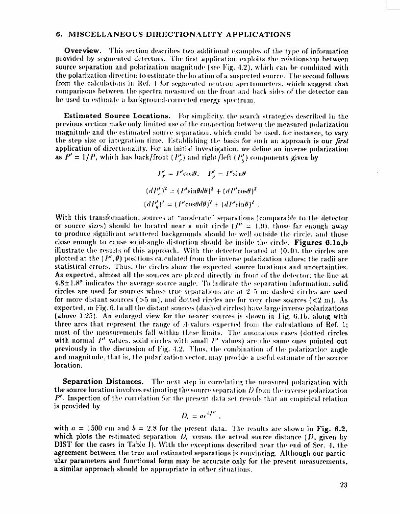
Separation Distances. “1’}1[’!1(’s1sf(*[)ill (“orrel;iting t lIo tllf~;isurd polilrization withthe source location itltdtm cst itll;itiIlg t }Iv s(mrcc wpar:it iwl /~ fro:ll t ti~jiu~crsv polarizationP’. inspection of t tw (x)rr(’lat ion for t II(I prrs(mt (I;it ii sot r(wxwls 1lIal ;III (’I1lpiriciil relation
is provided by
J], = (If “i” .
with a = 1500 cm and b = 2.8 for the present d;it;~. ‘1’lwresults are shown in Fig. 6.2.which plots the estimated separation D, versus the act IIiil sourcv distance ( l), gi~”enbyDIST for the cams in Table I). \\’ith the oxcepticms descril~~vlIlvar tile cn(i of Sec. .!. theagreement between the true a]ld estil;lilted separations is co]l~,inc-illg.Altllougll our partic-ular parameters and functional fornl may bc accurate on]y for the present nwasurcments,a similar approach SlIOIIld be appropri;~t o in ot her sit uat ioIls.
23

4
3
~
1d
‘Q,- 02’a.J!
u1
--2
0.4
().:.;
0.2
~ 0.1~
‘ 0.(!z2 –01
-0.2
–0.3
-0.4
,. ..’ . . . ..,’
7)”’ \fcasurc.fIl~J]Ls~nd ,.’”,.,
LJ”’ (,’alrbrtitiolls
b
:. :. ..,/ .. \.’;/, ‘“
(’ :,;;”-.=~”%+—4.—Y—. ,/(9 \ ,..D~LcclorIDCKIIIOII
> I I ,’ , , , I r
.-3 -2 --1 () 1 2 3 4 5
~GL]rce]DCZd,iOnfro[nIrwerse Pdwkd.iwl
.- ___
1-
(,●
—-
\
\/--.,
“’w.>~,,(~,J “
....~y ,k—-...*4,—0
..-–+:,,. r
“o. 3/) 4rr.
.— -— .. 4
\n a;
/ ‘1 //\, 3 !
\ I
i
MeasurcmejJ ‘. ‘~.CaIibrdions ‘. j’=. -,., //Cakwlat.ions
—. _—
(P 0.3 0.4 0.5 0.6 O.-/ 0.8 0.9 1.0 1.1 1213ack,hx]t(L))
Fig. 6.lii.b. Upperpanel(part a): Estimatedsourcelocations from in-verse Polarization values. The source andes ale obtained from the vectordirections, and the estimated separations are from the inverse magnitudes ofthe polarizations. The different circles indicate the statistical errors. Thelower panel (part b) k an enlargedsectionof par?.(a).
24
I
cc,-Z 1000”
EL‘“L
x‘z-7w
’10
‘1}”11(’ “.”S t’~<tllll; it(i(l I)lStilfl(Y.I
$!(f,)sllr.(r[lcr]t:● [2illl)I.iil 1(1:1s
;’ “
Id(;,l I{(+ull .,.“/
.
/’
, .;. //
. U::’ )
●m - ““ ●
.;,, s
.,-.,
... 1.
t~arkgrol;nd throughsuggest transmissionthesc \“aluesgi\.c the
L,
[
[= ~
[=:rL,
[
[
[-
[~.IL.—
[
,.
. .
[~-=
IL[.[ .[=[..[[r
L’rL.
[-
L2:)

‘1’holjat”kgrf~lili(!-slll)tr;lctd front-rfd yhdd is then
q).,= qbj– IIJ = (@~+ @~)/’2–B, .
As shown in Hef. 1, fIlis sul~tritct.ion rvducvs the front-rod detection efficiency by fractionsof 0.01, ().()74,().1JM.;tII(I().2!Mat tlic ffjllr f?llf~rgies,which can be corrected by dividing +~by g( ~,’)= ].02 – ().():jS~;,tlliit is, t}lt’]);i(”kgroll]lf]-(”f~rr(t(otcf]front-rod }“ie]d@leis
01. = ({~j- !( L’)$%)/g(f.’) .
The morv lilllited t’ll~’lg~’-i[i(lel)(~lldtjlltc;w procwls in the same way, hut substitutes con-stant values j( f; ) = ()..7and g( /; ) = ().78:
@l(.= (~~j– O..%>,)/().78 .
Transnlission Corrections. ‘1’hoIW’(1final l~”~ftl.+?lti,s.si~}~lrt)rrections arc similar to theon(t-sided approach. (,x( ”ol)t t II(I (f(jt(v”tor is ;iss II 111~1(1to IMI SII I}jwt tO ii strong directionalsignal flux with ;i w’(I;Iko]llllidi r(v”tiolla] sca It(Ir(vl I}a(”ligrouII(I. A kl]ow.rt fraction of the
directional flux is t r;i[Islllittod froth tho frimt into tho r~’arrods; subtracting this predictedleakage from the me;;surwl rear-rod flux pr(]~’ides;in witim;itc of thebackground, which c;ill in turn [w suht r;wtwf fro!!] the frtmt-rod flIIx. intransmitted flux. thr isotropir I)arkground. ;ind the CCJrKTkd yield are:
‘/; = J( /;)(0, + (;)Z;/2
/), = (O,j+ c).,)/2 - 7;
0,, = (0, - /1, ) .
~sumedisotropichis approach the
Again, the erlcrg}’-ill(l(~l~cl~~lclltcaso :;ubstitutw ii cw!stiint transmission value:
Averagedist rihut ion.
‘/; = ().5 (0, + fq)p
f), = (q+ o.! )/2–1;
0:,. = ( f.”)j – /), ) .
Correction. I“la(”)I (Jf thosr six ;Il)l)rtl;ichwi git”(’sa rwisorlafj]e background\l”c lt;i~v,1IIrroforv ii\”(’rilg4*(! t tif.’ rf:sl]lls tf~gvthi’r and addfd their t-ariance to
the stat istical ~~rrorI~I ~’stit[littc iilt (~~”~’rails}”st(IIIIAIir ll”llrortailjt}’. IIecause the front-rod(no-correction) ;ifid (Jlj($-sidwl;ippro;ictu$siiro suljj)(~rtt’d1)}-l)rt’~”iousstudiv$. these r.esu]ts
were gitxw mor~~vwigllt in I}watwraging. Figure 6.3 shows tho corrected spectrum & ob-tained for t~lf)‘sz(~fr;iliI)ration ru II. ,fs discussedin l{~~f.(j. the iigrecw]wi~with the expectedfission distribution is twr}”good at all energies abo~”vthe detector threshold near1 MeV.For this particular case. the l)a(;kgroull(l-sll}}tr;ic”tf~(]rvsuit is almost indistinguishable fromthe original front-rod spectrum. both in shape and magnit udr. In fact. the correction in-creases the area b). iil)oltt 1.3(X: this increase is w“itllinthe gcrmratcd uncertainty, which has
26
1=[—

10’
Id
10’
10°
10-’
0’
,J
t
● I+orltRods●
~J CorrcclrdW:f Ihstrltxjt ion
I r ,, I , !i r .’
Fig. 6.3. I;ront-rorl and lja{:kgro!lll[l-t”orrt.ct~jdcnvrgy spectra for the 2L2Cfcalibration run. Ikausc the sourceWM Iocatwi only S4 cm in front of thedetector, the backgroundcorrection is nrgligihlr. (F;rrorsare shown on thecorrecteddata only.) Th6 2>2(;fcurve is an cvaluatirm from Ref. 7,
increa..ed to 1.3% from a statistical error of 0.5%,. This conservative correction is reasonablein view of the relatively favorable gmmwtry used for the calibratio:] measurement.
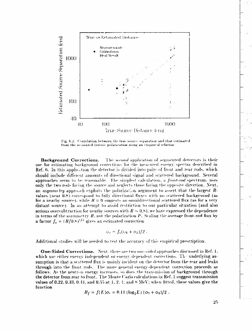
Background Systematic. To summarize our background discus~;irm.Fig. 6.4 showsthe observed relationship Iwtu’een the sig!lal/total ratios .5”/’/”and the measured asymme-tries R from all the data. As expect~ed,lower R-values correspond to larger backgroundestimates and lower S/7’ values. Most of the measurenwnts arc clustered in a narrow regionnear the calculated range of R-values. The S“/7’ratios for SOJJICruns (including the cali-brations) are slightly greater than 1.0, because SOJIJesource separations are so small thatsolid-angle effects lead to high a..ymnwtrics. The daslwd line shows the empirical functionS/T = 1.11?*14, which is constrained to pas through the predicted value of 1.0 at R = 0.62.Note that the lowest .5”/7’ratios of 0.8 -0.!) correspond t.o .5”/fJ‘:alues of about 6:1, whichare much higher than the 1:1 rat io estimated in SCcs. :1-4. This difference is associatedwith the wider range of background estimates included in the a~wrage value obtained inthis section.
Discussion. The two applications described in this section are based onthe polarizationanalyses in Sec. 4 and the earlier calculations of Ref. 1. Both discussions are constrainedby the limited range of variation in the present measurements, which were not originallyintended as a study of the detector’s directional capabilities, and additional experimentswill be needed to examine the reliability of the different techniques.
27

().1Asylr 1I I I( ‘1f’}
5Tlgllill,f’lt)t.ili i{; ltl(;vs Asyr1]j11(4 I“y
J Mr,i:surcvn(vh● (~illltJf’ii(lOIIS b
‘— (“,11(111;11(![1Vdllws
..——
; -I
22 ,). .’,
i“ V ‘“,5. .-
ii
i
,,,
1
7. CONCLUSIONS
Polarized Fields and Directional Detectors. !1} collltjining tlw hasic directionalconcepts int roducod iII Ref. 1 ui th ;i IiIl]ild sot of fnwsu rorlrents for realistic neutronsources, this report lI;ISdevolopd aII ulldersl;inding of 1hf’ itdviintagos of directional mea-srlrenlents for the loc;iriw ofscrurcos fJf n Ircloarr;idiat ion. ~lfter the hri~>frmicw of the lm..icdetector opmations ill %“. 2. sfv”. :] ir]tr(J(lll(_(>S t II(I c(J1lropts of polarized radiation fieldsand direct iorral radi;!ti~wdotortors. w’hirllpro~,idc it no~wl;ipproach to the critical searchprohlwn of (iislingui>llillgt)(*t\\wfw signal and hackgrourld. IN hoth the present approachand in corlt’cmtional1tx”hIli(lues. it is t IIP gradif nl of t Iv ritdia~ion field that provide: thesource signat Ilre. lrl ;t corlixw~ionalapproac]l. mw-isurernmltsat difrmwlt locations, withthe attcfldant diffvrf~]lcf’sill hackgrolltltl rates. are US(XI to (l(’t OrilIi Ilf~ this si~nattire; ourapproach measures t II(I10(”iiigradient at a singlo position and therefore clirl]inates much ofthe backgrour)d Pro])](’!lt.
Mathematical Formalism and Experimental Demonstrations. Our concept ofa polarized radiatiorl Iiehl leads t.o tv;t~import iir:t J)rf’(lirti(ms that connect the polarizationdirection with the s~)llrce;ingle and tho polarization ]ll~gllitude with the local signal-to-backgroun(f ratio, a]l(l hence the source separatiorl. IN %-. 1. uc &Mx40pthe techniquesfor expressing tfwse concepts in terms of rlwasurahlv quantities h}. adapting the formal-ism usrxi for polarizat ion ohservahles. ;Md wv provide the experimental verification of thepredictions by taking advantage of itn existing protot}qw dctertor and the data sets fromprevious experiments. With this foundation we can readily demonstrate angle accuracieswithin +5° for hotll jmint sources and (listributed ohjccts. In SCcs.4 and 6 we also showthat the polarization] Inagnitudo not onl}. changes with inr-roasing source separation: its
i=
,=
,=
I~=
~=
I.—
,=I;=
~-1-:—11!=
I1=
.—!1
~—
,
,–
rI:=
I
l—
28

ACKNOWLEDC RII;NTS
REFERENCES
I
l–
,=
I
,=
1“l–~–.,—;.,....,,-#,-,...
. U S GO’/ CR?JM[NT PRINTING OFFICE 1993 (J 5?3 024 ,?7042