me7070/forsyth cor ndt from c con in... · 2010-10-27
TRANSCRIPT
5Nondestructive testing of corrosion
in the aerospace industry
D. S. FOR S Y T H, TRII Austin, USA
Abstract: Methods of nondestructive testing (NDT), any test that doesnot impair the function of the test subject, are described. Owing to thediversity of corrosion damage that occurs on the variety of engineeringmaterials in the aerospace industry, there are a number of NDT methodsthat have been applied. A clear understanding of the corrosion damageand the effect of the damage on structural integrity is necessary toproperly specify an NDT method for corrosion.
Key words: nondestructive testing, radiography, ultrasound, eddy current,enhanced visual testing, corrosion, aerospace industry.
5.1 Introduction to nondestructive testingNondestructive testing (NDT) is defined by the American Society forNondestructive Testing (ASNT) as: 'The determination of the physical con-dition of an object without affecting that object's ability to fulfill its intendedfunction. Nondestructive testing techniques typically use a probing energyform to determine material properties or to indicate the presence ofmaterial discontinuities (surface, internal or concealed)'. For the purposeof this article, the terms nondestructive testing, nondestructive inspection(NDI), and nondestructive evaluation (NDE) will be considered to beequivalent.
In the modern NDT paradigm, the uses of NDT can be broken intoseveral categories where it plays an important role:
• Material property measurements• Process design for materials manufacturing• Online process control• Quality control as various stages of manufacturing are completed
In addition, NDT plays an important role in the continued safe operationof physical assets. For instance. NDT is being used in conventional inspec-tions and in health monitoring, where NDT sensors arc embedded orattached to the system being inspected or monitored for defects or damage.
111

Related titles Corrosion control Inthe aerospace
industry
Aircraft system safety: military and civil aeronautical applications(ISBN 978-1-84569-136-3)Demonstrating safety for the application of ever more complex technologies is aformidable task. System engineers often do not have the appropriate training, areunfamiliar with the range of safety approaches, tools and techniques, and theirmanagers do not know when and how these may be applied and appropriatelyresourced. Aircraft system safety provides a basic skill set for designers, safety prac-titioners, and their managers by exploring the relationship between safety, legallia-bility and regulatory requirements. Different approaches to measuring safety arediscussed, along with the appropriate safety criteria used in judging acceptability.Engineering students, designers, safety assessors (and their managers), regulatoryauthorities (especially military), customers and projects teams should find Aircraftsystem safety provides an invaluable guide in appreciating the context, value andlimitations of the various safety approaches used in cost-effectively accomplishingsafety objectives.
Techniques for corrosion monitoring(ISBN 978-1-84569-187-5)Corrosion monitoring technologies are a vital step in efforts to combat corrosion,which can have major economic and safety implications. The first part of the bookreviews electrochemical techniques for corrosion monitoring. A second group ofchapters analyses other physical or chemical methods of corrosion monitoring. PartIII examines corrosion monitoring in special environments and conditions. Section[V covers the selection of monitoring techniques and probes and a final group ofchapters discusses applications and case studies.
The air transport system(ISBN 978-1-84569-325-1)Major operational elements of the world air transport system are examined in thisimportant book, which provides an invaluable single information source to manag-ers in all air transport sectors. Initial chapters consider route structure options interms of operational impacts and describe the context and boundaries of the indus-try - the natural, regulatory and operational environments. These introduce 'systems'perspectives that integrate the content of further chapters, examining aircraft, air-lines, airports and airspace issues. Finally, the challenge of ensuring symbiosis of allelements of the changing scene and the scope for developing strategies that will suita balance of all stakeholder requirements are considered in depth.
Details of these and other Woodhead Publishing books can be obtained by:
• visiting our web site at www.woodheadpublishing.com• contacting Customer Services (e-mail: [email protected]; fax:
+44 (0) 1223 893694; tel.: +44 (0) 1223 891358 ext. 130; address: Woodhead Pub-lishing Limited, Abington Hall, Granta Park, Great Abington, Cambridge CB216AH, England)
If you would like to receive information on forthcoming titles, please send youraddress details to: Francis Dodds (address, tel. and fax as above; e-mail: [email protected]). Please confirm which subject areas you arcinterested in.
Edited bySamuel Benavides
oCRC Press
Boca Raton Boston New York Washington, DC
WOODIIEAD PUBLISIIING LIMITEDCambridge New Delhi

Published by Woodhead Publishing Limited, Abington Hall, Granta Park,Great Abington, Cambridge CB21 6AH, Englandwww.woodheadpublishing.com
Contents
Woodhead Publishing India Pvt Ltd, G-2, Vardaan House, 7/28 Ansari Road,Daryaganj, New Delhi - 110002, India
Published in North America by CRC Press LLC, 6000 Broken Sound Parkway, NW,Suite 300, Boca Raton, FL 33487, USA
First published 2009, Woodhead Publishing Limited and CRC Press LLC© 2009,Woodhead Publishing LimitedThe authors have asserted their moral rights.
This book contains information obtained from authentic and highly regardedsources. Reprinted material is quoted with permission, and sources are indicated.Reasonable efforts have been made to publish reliable data and information, butthe authors and the publishers cannot assume responsibility for the validity of allmaterials. Neither the authors nor the publishers, nor anyone else associatedwith this publication, shall be liable for any loss, damage or liability directly orindirectly caused or alleged to be caused by this book.
Neither this book nor any part may be reproduced or transmitted in any formor by any means, electronic or mechanical, including photocopying, microfilmingand recording, or by any information storage or retrieval system, without permis-sion in writing from Woodhead Publishing Limited.
The consent of Woodhead Publishing Limited does not extend to copying forgeneral distribution, for promotion, for creating new works, or for resale. Specificpermission must be obtained in writing from Woodhead Publishing Limited forsuch copying.
Contributor contact details x
1 Corrosion in the aerospace industry 1S. BENAvlDEs, US Coast Guard Aging Aircraft Branch,USA
1.1 Introduction 11.2 Aerospace corrosion 21.3 Impact of corrosion 41.4 Corrosion prediction 71.5 Conclusion 131.6 Sources of further information and advice 131.7 References 13
Part I Corrosion fundamentals and cost of corrosion 15
2 Assessing the cost of corrosion to theaerospace industry 17E. HERZBERG, LMI Research Fellow, USA
2.1 Introduction 172.2 Corrosion impacts 182.3 Corrosion cost elements and characterizations 192.4 Corrosion cost measurement methodology 232.5 General case studies 312.6 Conclusion :n2.7 References 332.8 Appendix A: Cost element definitions 332.0 Appendix 13:Typical corrosion activities 34
Trademark notice: Product or corporate names may be trademarks or registeredtrademarks, and are used only for identification and explanation, without intent toinfringe.
British Library Cataloguing in Publication DataA catalogue record for this book is available from the British Library.
Library of Congress Cataloging in Publication DataA catalog record for this book is available from the Library of Congress.
Woodhead Publishing ISBN 978-1-84569-345-9 (book)Woodhead Publishing ISBN 978-1-84569-553-8 (e-book)CRC Press ISBN 978-1-4200-7965-4CRC Press order number: WP7965
The publishers' policy is to use permanent paper from mills that operate asustainable forestry policy, and which has been manufactured from pulp which isprocessed using acid-free and elemental chlorine-free practices. Furthermore.the publishers ensure that the text paper and cover board used have metacceptable environmental accreditation standards.
Typeset by SNP Best-set Typesetter Ltd., Hong KongPrinted by TJ International Limited. Padstow, Cornwall. England

112 Corrosion control in the aerospace industry Nondestructive testing of corrosion in the aerospace industry 113
In all cases, the customer must define the requirements of the test, such asthe minimum level of acceptability for the property being measured andthe characteristics of the material discontinuities to be identified. Giventhis information, the NOT engineer or experienced technician can choosethe appropriate method and develop an appropriate technique for theinspection requirements.
An NOT method is classified according to its underlying physicalprinciple. For example, the common methods are:
• Visual and optical testing (VT),• Radiographic testing (RT),• Electromagnetic testing (ET),• Ultrasonic testing (UT),• Liquid penetrant testing (PT),• Magnetic particle testing (MT),• Acoustic emission testing (AE), and• Infrared and thermal testing (IR).
An NOT technique defines all the parameters for the application of aspecific method to a specific problem. These parameters include the instru-ments, probes, acceptance criteria, calibration specifications, and muchmore. ASNT offers a series of handbooks that are a key reference for thepractical implementation of NOT. The following sections will briefly describeeach of the common methods listed above. Portions of the text are taken(with permission) from Matzkanin and Yolken (2007).
Several programs currently in progress in the United States and othercountries are attempting to improve upon this state of affairs by developinganalytical capabilities for corrosion damage assessment in aircraft struc-tures. These analytical models will require, as input, quantified corrosiondamage data from NOT. The outputs from the corrosion damage assess-ments will allow the planning of maintenance actions depending on thecurrent state of corrosion, its influence on structural integrity, and its pro-jected growth. The outputs of these programs will then provide moredetailed requirements and cost justification for the use of advanced NOTfor corrosion.
5.1.1 Requirements for corrosion nondestructive testing
NOT is one element in the life cycle management of aircraft. It is integrallyrelated to the methods used to assess structural integrity and risk assess-ment: these set the requirements for NOT. The aerospace communitydesigns and maintains aircraft by either damage tolerance or safe lifeapproaches. Both of these, in the current operational environment, arebased on crack growth and elimination of other damage mechanisms suchas corrosion through maintenance and repair. In this environment, therequirements for NOT for corrosion are not well defined. This author hasheard from civilian and military regulators that 'we don't fly planes withcorrosion', despite all evidence to the contrary.
The difficulty of the current situation, 'find and fix', is that it precludesuse of sensitive NOT in instances where operators feel through experiencethat corrosion is not an issue. If corrosion damage is found at an early stagewhere there is no immediate safety impact, operators still feel compelledto take maintenance action immediately instead of deferring to a later,more convenient opportunity.
5.1.2 Visual nondestructive testing
By far, the most common NOT method is visual and optical testing. In manyinstances, a trained inspector armed with simple tools, such as a flashlightand magnifying glass, can perform a very effective inspection. In qualitycontrol, as well as in maintenance operations, visual testing is the first lineof defense. When deciding whether to use visual testing, it is important tounderstand its potential as well as its limitations. If the visual method is notsufficient for the problem at hand, more complex methods must be consid-ered. Using the visual inspection method for enclosed systems can bechallenging and possibly ineffective. To enable a technician or engineer toinspect these difficult-to-see areas, a device known as a borescope is oftenused. Borescopes are essentially miniaturized cameras that can be placedon the end of a fiber optic cable. The camera can then be inserted intoregions that are obstructed from direct visual inspection, and the resultingimages are viewed in real-time on a video screen by the inspector.
5.1.3 Enhanced visual/optical nondestructive testing
There are a variety of enhanced visual/optical NOT methods available. Interms of corrosion NOT, these methods are generally used to detect andmeasure deformations on surfaces. These deformations may be caused bypitting on the exposed surface, or by subsurface corrosion damage in built-up structure. There are a number of implementations of instruments basedon Moire, electronic speckle pattern interference (ESP!) and digital specklecorrelation (Jin and Chiang. 1998). and holography. Other optical surfacetopography systems have been used for characterization of corrosiondamage (Komorowski ('I al., IY96. Forsyth 1'1al.• IYY7). Direct optical metrol-ogy methods such as laser interferometry and triangulation-based methodshave been used in laboratory-type situations for measuring pillowing causedby corrosion in thin aluminum structures (Eastaugh ct al.. IY9k).

114 Corrosion control III the aerospace industry Nondesuuctivo tcstlll\J 01 C(HIOSllJli III the aerospace industrv 115
5.1.4 Ultrasonic nondestructive testing
Ultrasonic testing (UT) employs an extremely diverse set of methods basedupon the generation and detection of mechanical vibrations or waves withintest objects. The test objects are not restricted to metals, or even to solids.The term ultrasonic refers to sound waves of frequency above the limit ofhuman hearing. Most ultrasonic techniques employ frequencies in the rangeof 1 to 10 MHz. The velocity of ultrasonic waves traveling through a mate-rial is a simple function of the material's modulus and density, and thusultrasonic methods are uniquely suited to materials characterization studies.In addition, ultrasonic waves are strongly reflected at boundaries wherematerial properties change and thus are often used for thickness measure-ments and crack detection. Recent advances in ultrasonic techniques havelargely been in the field of phased array ultrasonics, now available in por-table instruments. The timed or phased firing of arrays of ultrasonic ele-ments in a single transducer allows for precise tailoring of the resultingultrasonic waves introduced into the test object.
indicative of problems. Imaging of test objects after the application ofenergy can be used to monitor the flow of heat in the object, which is afunction of material properties as well as boundaries. Flash thermographytechniques have been very successful in imaging disbonds and delamina-tions in composite parts, for example. The high cost of quality thermalcameras was previously a drawback of the infrared (IR) method, butrecently these have become significantly less expensive. Another significantrecent advancement is the use of mechanical energy to stimulate localizedheating at subsurface discontinuities, such as cracks in metals, opening upa new field of application for the IR method.
5.1.5 Eddy current nondestructive testing
Electromagnetic testing (ET), especially eddy current testing, is commonlyused to inspect objects throughout their life cycle. Eddy current techniquesemploy alternating currents applied to a conducting coil held close to thetest object. In response, the test object generates eddy currents to opposethe alternating current in the coil. The eddy currents are then sensed by thesame coil, separate coils, or magnetic field sensors. Changes in the inducededdy currents may be caused by changes to a material's electromagneticproperties and/or changes in geometry, including the abrupt changes incurrent flow caused by cracks. Thus, ET methods are highly effective for thedetection of cracks present on or below the surface of metallic objects. ETequipment has become extremely portable and is relatively cheap. It is thesecond most common method specified for NOT of aircraft. Recent advancesin eddy current technology include multi-channel portable instruments,allowing faster inspections of large areas, and new magnetic sensors, suchas the giant magnetoresistive sensors (GMR) developed for computer harddrives, instead of coils.
5.1.7 Radiographic nondestructive testing
Historically, radiography is the next most common NOT method. Signifi-cant activity in the field occurred almost immediately after Roentgen's dis-covery of x-rays in 1895.Early literature notes the ability of radiographs todetect discontinuities in castings, forgings, and welds in metals. Discontinui-ties such as pores or inclusions in metals are readily detected in many cases.Cracks may also be detected using radiographic techniques, but attentionmust be paid to orientation and residual stress issues. Radiography contin-ues to be widely used despite the expense and safety implications of theequipment. Recent advances in digital radiography have helped reduce thecost of employing this method by eliminating the use of film.
5.1.8 Additional nondestructive testing methods
5.1.6 Thermographic nondestructive testing
There are a number of other NOT methods that have been used for corro-sion NOT. These include the magneto-optic imager (MOl), a commercialdevice that images magnetic fields induced by a sheet current (Thomeet aI., 1996). Microwave NOT methods have been used to find corrosionunder paint layers (Hughes et al., 2003). Terahertz imaging is being used tofind corrosion damage under thermal insulation tiles on the space shuttle(Anastasi et aI., 2007).
Health monitoring for corrosion is a growing field, with the potential toreduce the impact of disassembly and reassembly of aircraft to enabletraditional NOT. Some of the sensor types are direct evolutions of NOTmethods, and are simply attached to the structure to be left in place. Thistopic is covered in chapter 7.
Infrared and thermal testing methods are characterized by the use ofthermal measurements of a test object as it undergoes a response to astimulus. Thermal imaging cameras are the most common sensing method.Passive imaging of machinery or electronics may be used to detect hot spots
5.2 Data fusion for nondestructive testingThe complexities of corrosion damage. and the fact that inspections forfatigue damage ~IIT often carried out Oil the same structure. means that the

116 Corrosion control in the aerospace incJustry
maintainer may end up with multiple inspections on the same structure,each with a fraction of the total information needed to make maintenancedecisions. Data fusion is required to make sense of the multiple sources ofinformation, whether it is done manually by the inspector or engineer, orwhether it is computer assisted.
A simple definition of data fusion is the combination of multiple inputsinto one output. Thus, data fusion includes basic systems such as voting (ifa majority of inputs are true, the output is true) as well as highly complexsystems such as military target tracking or remote sensing using multipleband radars operating in different locations. There are three general catego-ries used to describe the level at which data fusion takes place. Pixel leveldata fusion describes applications where little or no preprocessing is appliedto the data, and the fusion operation acts on the lowest level of the data.Feature level fusion refers to cases where feature extraction has been per-formed on the data before fusion. Finally, decision level fusion refers to thefusion of data that is carried out after feature extraction and identificationon the data inputs. The results reported in this work use pixel-level fusionalgorithms. Some applications of data fusion to NDT have been published,most of which are of moderate complexity (for example Gros, 1997 andGros, 2001) and involve pixel or feature level fusion. This author has previ-ously applied simple data fusion methods on NDT results to identify andmeasure corrosion in aircraft structures (Forsyth and Komorowski, 2000);the work presented in that paper used NDT from commercially availableinspection equipment and applied more advanced fusion techniques toyield quantitative estimates of the thicknesses of individual layers of atwo-layer lap joint.
The generic steps required to perform data fusion on NDT data are:
• inspection preprocessing,• registration of individual inspections on a common coordinate system,
and• data fusion.
It is important to note that the steps of preprocessing and registrationare in themselves value-added steps. Even before any data fusion operationhas been performed, the NDT data from disparate sources have beenbrought together on one software platform, and registered on a commoncoordinate system. This is a significant improvement over most currentpractices for handling NDT data, and greatly facilitates the use of databasesfor maintenance planning. It also allows improved inspector interpretationby making comparison between NOT data much simpler. Often the pre-processing step can be used to transform a single NDT data source fromthe NDT domain to a quantitative measure; for example, 'Edge of Light'
Nondestructive iesunq of corrosion III the aerospace industrv 117
images can be transformed from brightness levels to images of maximumpillowing deformation (Forsyth and Komorowski, 2(00).
The final data fusion algorithm to be used will be specific to the applica-tion. Development of these algorithms will only be cost-effective forrepetitive inspection situations, such as the common lap splice joint.However, the preliminary steps of data handling, preprocessing, and regis-tration are likely to become more commonly used as fleet maintenancepractices are modernized, reducing the costs of implementing data fusionin practical situations.
5.3 Reliability of nondestructive testing for corrosionWhen NDT is used as part of the management of risk in the life cyclemaintenance of an aircraft, it is imperative to know what is the probabilityof finding (or equivalently of missing) discontinuities of interest in aninspection. This is usually called the probability of detection (POD). Thedevelopment of the POD metric was originally directed towards fatiguecracks, but it is important to note that the POD approach is not limited tocracks, and has in fact been applied to other discontinuities such as corro-sion loss, impact damage, or delaminations (Forsyth et al., 1998). The currentPOD approaches present POD as a function of a single metric of damage,for example crack length, as shown in Fig. 5.1. In cases where the corrosiondamage of interest can be characterized by a single metric, the conventional
100
90 Data set: DC001(3)DTest object: longitudinal cracks in
2219 aluminum, GTA,flush ground welds
Condition: as crackedMethod: ultrasonic shear waveOperator: combined, 3 operators
Opportunities = 345Detected = 29190% POD = 0.030 in. (7.54 mm)False calls = not documented
- Mean pod. HiVmiss data
~ 80~s 70
g 60Qi'0 50'0g 40
~ 30.0£ 20
10
o0.00 0.05 0.10 0.15
Actual crack depth (in.)0.20
5.1 An example of a POD curve, from the ultrasonic inspection ofwelds in aluminum for cracks (from Rummel and Matzkanin 1996,used with permission).
118 Corrosion control in the aerospace industry Nondestructive testinq or corrosion ill tile aelospace industry 119
POD approaches will be suitable. This may be the case for intergranularcracking and pitting on an exposed surface. In other cases, multi-dimensional damage is not well characterized by a single metric, and anumber of approaches have been developed.
Both the USAF (USDa D, 1999) and the United States Federal AviationAgency (FAA) (Spencer et al. 1993a, 1993b and Spencer and Schurman,1995) have published guidelines that describe in detail the experimentsrequired to estimate the POD of an inspection system. These documentsare in the public domain, and can be obtained for free from the respectivegovernment agencies as well as the Department of Defense's AdvancedMaterials, Manufacturing, and Testing Information Analysis Center(AMMTIAC). The USAF MIL-HDBK-1823 is being updated as this bookgoes to press.
There are a number of useful general statements that can be made aboutestimating POD. The process of POD estimation requires a number ofinspections to be performed:
• using the complete, pre-defined inspection system that is being assessed:o including representative equipment, procedures, inspectors, and target
parts;• using parts with discontinuities that represent the discontinuities of
interest:o or a means to assess the difference between the two, for example,
using machined notches or flat bottomed holes can provide a usefulmeasure of capability, but should not be assumed to be representativeof cracks or other natural discontinuities; and
• using an inspection procedure and environment typical of the deployedenvironment:o human factors studies have shown that the relationship of factors such
as environment (lighting, temperature, etc.), training, experience,motivation and others is not simple and often not intuitive.
It is key to understand the physical parameters that may affect theresponse of the NOT system to a discontinuity to be able to execute a rep-resentative POD estimate. If parts from service, with discontinuities arisingfrom service, are available; this is the optimal situation. However, in mostcases, this is not possible. Therefore, every reasonable effort should be madeto replicate the service discontinuities as close as possible, or to use engi-neering judgment as to whether safety factors are needed to account forthe difference between the POD experiment and in-service conditions.
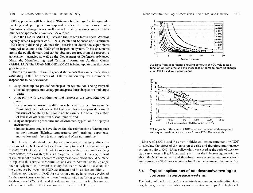
Unique approaches 10 POD for corrosion damage have been developedfor the case of corrosion in the internal surfaces of aircraft sk in splice joints,Ashbaugh ('( al. (20(JI) showed that detection of corrosion in this case \Vas:1 rlllll'liOIl or h(llh t h« thickness I{)~~;IIHI art'a :rlTt'l'i<'d (h,l'" S.").
8
~7'; 6 ... ------ ... -' -- ..... --.!!!. 5' -+- 0.9<Il ,--- ---08
~ 4 .•• 0.7
15 3 ~0.6~ 2 ~0.5" ~0.4--+- 0,3
-0.2-0.1
5 10 15 20 25 30Percentcorrosion
5.2 Data from experiment. showing contours of POD values as afunction of both area and thickness loss of damage (from Ashbaughet al, 2001 used with permission).
-,~
~ 12r;:=::=- -=============_--~ 11t--~ ,'--~:E 10 - ~si.r.I.&~IJ/qC,- • • • • ..,., C1[!(J. (f""?;::-..16 9 ' .. , , " ••.-". elJ~ '- ~iJf "'_ 'Po 8 -0 ..•.. "J- CA .; ~'-s..ci qCfi ".::'C.. •E 7,----· req:'," .....e i.t(1fIo '. . ' •.....•......•-;;; 6 :-'- _ __ _<f)
2. 5r--'-<f)
gJc~o:cf-
4 t ' ! I I I
0.00 0.50 1,00 1.50 2.00Standarddeviationof NOI error (in, x 10-3)
2,50
5.3 A graph of the effect of NOT error on the level of damage andsubsequent maintenance actions from a KlC-135 case study.
Liao et al. (2003) used the error in thickness loss measurement by NDTto calculate the effect of this error on the risk and therefore maintenanceactions required. K/C-J35 lap splice joints were used as the basis of this casest udy. As shown in Fig. 5.3, increasing error results in increasing uncertaintyabout the NOT assessment and, therefore, more severe maintenance actionsare required as NDT error increases for the same estimated thickness loss.
5.4 Typical applications of nondestructive testing tocorrosion in aerospacesystems
The design of modern aircraft is a relatively mature engineering discipline,1:lrgelv progressill? by evolutionary nut revolutionary steps. AI :1 high level.

120 Corrosion control in the aerospace industry ~~ondcstructive tustllig of corrosion III tho il()I()5;PClCl~ Illdu:)tIY 121
5.4 A photograph of a row of fasteners from the upper wing skin of aBoeing 707, showing exfoliation damage and grinding marks fromrepairs (from Forsyth et al. 2002). The material is 7178-T6 aluminum.
5.6 From top to bottom, a photograph, a UT image, and an IR imageof a section of wing plank from a Boeing 707, showing exfoliationdamage and grinding marks from repairs. The UT image wasassembled from a mechanical scan of resolution 1 mm in both x andy directions. The IR image is from a 320 x 240 pixel camera. Thematerial is 7178-T6 aluminum.
5.5 Metallographic section around a fastener hole in a Boeing 707wing skin plank, showing multiple layers of intergranular attack frompits in the countersink. The material is 7178-T6 aluminum. to skin joints or splice joints, and skin to substructure joints. These joints
are formed in a variety of different designs, but in general are riveted. Someearly designs, notably the K/C-135, utilize spot welds in some of the splicejoints. A sealant or adhesive layer is usually included, but not relied uponfor structural capability.
These structures are predominantly manufactured from 2024-T3 alumi-num sheet. Significant efforts have been expended by numerous agenciesto characterize the corrosion and fatigue behaviors of splice joints madefrom AI 2024- T3.
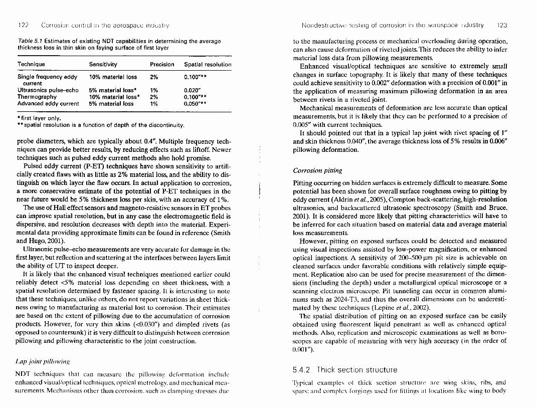
Most NOT techniques developed for the detection of corrosion in lapsplice joints measure the average thickness loss due to general attack andpitting corrosion. Often these techniques are only capable of measuring thison the faying surface of the first layer. Estimates of the performance ofsome of these techniques are summarized in Table 5.1. The data in the tableis it summary of results from various reports (see Hoppe ('( al., 2()()2, Lepine1'/ II!. 2(l(l2).
To date, single frequency FT methods have demonstrated a sensitivity toI (l'X) material loss Oil the first or second layer of multi-layer specimens, withprecision oi 2% oi toLd 1;IH'l thickness. with sp;ltial resolutions limited to
there are strong similarities in structures and engines across rotary aircraftand fixed-wing aircraft from fighters to transports. In this chapter, wedescribe common design details that may be susceptible to corrosion, andhow NOT is applied to these design details.
In order to define our nomenclature for the following, at its simplest, wecan think of the design of aircraft structures as consisting of two majorcomponents: fuselage and wings. The fuselage typically is constructed ofhorizontal stringers, circular frames, and skins. The wing is similar, with sparsrunning perpendicular to the fuselage, ribs running parallel to the fuselage,and skins. Horizontal and vertical stabilizer structures are usually similar tothe wing construction and nomenclature.
5.4.1 Multi-layer thin structures
First we consider multi-layered thin structures. By thin, we arhitrarily choose0.250" as a guide. The' key structural clements ill this category <Ire the skill
122 Corrosion control 111 tho aerospace industlY I\]OlldestluctlVC testing of corrosion in tho aerospace industry 123
Table 5.1 Estimates of existing NDT capabilities in determining the averagethickness loss in thin skin on faying surface of first layer
to the manufacturing process or mechanical overloading during operation,can also cause deformation of riveted joints. This reduces the ability to infermaterial loss data from pillowing measurements.
Enhanced visual/optical techniques are sensitive to extremely smallchanges in surface topography. It is likely that many of these techniquescould achieve sensitivity to 0.002" deformation with a precision of 0.001" inthe application of measuring maximum pillowing deformation in an areabetween rivets in a riveted joint.
Mechanical measurements of deformation are less accurate than opticalmeasurements, but it is likely that they can be performed to a precision of0.005" with current techniques.
It should pointed out that in a typical lap joint with rivet spacing of 1"and skin thickness 0.040", the average thickness loss of 5% results in 0.006"pillowing deformation.
Technique Sensitivity Precision Spatial resolution
Single frequency eddy 10% material loss 2% 0.100"**current
Ultrasonics pulse-echo 5% material loss* 1% 0.020"Thermography 10% material loss* 2% 0.100"**Advanced eddy current 5% material loss 1% 0.050"**
*first layer only.** spatial resolution is a function of depth of the discontinuity.
probe diameters, which are typically about 0.4". Multiple frequency tech-niques can provide better results, by reducing effects such as liftoff. Newertechniques such as pulsed eddy current methods also hold promise.
Pulsed eddy current (P-ET) techniques have shown sensitivity to artifi-cially created flaws with as little as 2% material loss, and the ability to dis-tinguish on which layer the flaw occurs. In actual application to corrosion,a more conservative estimate of the potential of P-ET techniques in thenear future would be 5% thickness loss per skin, with an accuracy of 1%.
The use of Hall effect sensors and magneto-resistive sensors in ET probescan improve spatial resolution, but in any case the electromagnetic field isdispersive, and resolution decreases with depth into the material. Experi-mental data providing approximate limits can be found in reference (Smithand Hugo, 2(01).
Ultrasonic pulse-echo measurements are very accurate for damage in thefirst layer, but reflection and scattering at the interfaces between layers limitthe ability of UT to inspect deeper.
It is likely that the enhanced visual techniques mentioned earlier couldreliably detect <5% material loss depending on sheet thickness, with aspatial resolution determined by fastener spacing. It is interesting to notethat these techniques, unlike others, do not report variations in sheet thick-ness owing to manufacturing as material lost to corrosion. Their estimatesare based on the extent of pillowing due to the accumulation of corrosionproducts. However, for very thin skins «0.030") and dimpled rivets (asopposed to countersunk) it is very difficult to distinguish between corrosionpillowing and pillowing characteristic to the joint construction.
Corrosion pitting
Pitting occurring on hidden surfaces is extremely difficult to measure. Somepotential has been shown for overall surface roughness owing to pitting byeddy current (Aldrin et al., 2(05), Compton back-scattering, high-resolutionultrasonics, and backscattered ultrasonic spectroscopy (Smith and Bruce,2001). It is considered more likely that pitting characteristics will have tobe inferred for each situation based on material data and average materialloss measurements.
However, pitting on exposed surfaces could be detected and measuredusing visual inspections assisted by low-power magnification, or enhancedoptical inspections. A sensitivity of 200-500!lm pit size is achievable oncleaned surfaces under favorable conditions with relatively simple equip-ment. Replication also can be used for precise measurement of the dimen-sions (including the depth) under a metallurgical optical microscope or ascanning electron microscope. Pit tunneling can occur in common alumi-nums such as 2024-T3, and thus the overall dimensions can be underesti-mated by these techniques (Lepine et al., 2002).
The spatial distribution of pitting on an exposed surface can be easilyobtained using fluorescent liquid penetrant as well as enhanced opticalmethods. Also, replication and microscopic examinations as well as boro-scopes are capable of measuring with very high accuracy (in the order of0.001 ").
Lap joint pillowing
NOT techniques that can measure the pillowing deformation includeenhanced visual/optical techniques, optical metrology, and mechanical mea-surements. Mechanisms other than corrosion. such as clamping stresses due
5.4.2 Thick section structure
Typical examples of thick section structure arc wing skins. ribs, andspars: and complex forgiflgs used for fittings at locations like wing to body

124 Corrosion control in the aerospace industry Nondestructive testing 01 corrosion in the aerospace industry 125
attachment points. These structures are commonly manufactured from 7000series aluminum alloys, 7075-T6 being common on older aircraft. Morecorrosion resistant alloys are generally used in modern designs.
Because of the materials and product forms typical of these structures,intergranular corrosion attack is a common problem. This attack begins atpitting at exposed grains, and quickly becomes intergranular in nature. Ifsustained stresses are present, due to residual stresses or even simple 'weighton wheels' loads, the phenomenon often called 'stress corrosion cracking'can result.
In a number of cases, inspection may be only an interim solution, provid-ing time for material substitution programs. Any pitting on highly loadedforgings of AI 7075-T6 is capable of nucleating intergranular cracking. Ifthese components are exposed for visual inspection, this may be sufficient.Interesting case studies include the C-130 'pork chop' fitting and the C-141landing gear hub (Brooks et al., 2001).
Depth location of intcrgranular corrosion
As described above, using UT techniques, it is relatively simple to deter-mine the depth of the first layer of exfoliation that extends beyond fasten-ers. Accuracy in thick sections should be 0.005" or better in depth. Moreadvanced UT techniques can interrogate the bottom of the fastener holeand locate the bottom layer. Accuracy of 0.010" is probably achievableunder well-controlled situations.
Corrosion pitting
Pitting attack can occur on thick section components, and can be structur-ally significant. The same NDT issues apply here as described in section5.4.1.
Extent of intergranular corrosion
Exfoliation that extends beyond the fastener head can be detected bysimple UT and IR methods, as well as enhanced visual methods. Sizing forall these methods is limited by probe sizes and in the case of IR methods,diffusion. UT is the most accurate sizing method, and a measurement accu-racy of 0.010" should be achievable. The sensitivity of IR methods is moreaffected by the depth at which the exfoliation occurs, and this is not wellknown.
5.4.3 Engine components
Intergranular and exfoliation attack
A number of the 7000 series aluminum alloys that were commonly used inaircraft manufacture are susceptible to intergranular attack. These include7078, 7079, and 7075 in the T6 temper. The T6 temper was popular due toits high strength. Typical applications on a transport aircraft include upperwing skins, spars, and ribs.
Intergranular attack commonly nucleates at corrosion pits on exposedendgrains. Holes with steel fasteners are a common site, as fretting eventu-ally wears off the coatings designed to isolate the steel from the aluminum.In severe cases, the material bulges around the fastener due to the corrosionproduct between multiple intergranular cracks. This is called exfoliation.
This type of damage is relatively easy to detect, especially once it hasprogressed beyond the countersink of the fastener. Even before it is visibleas exfoliation, UT and IR methods can readily detect it, but will onlymeasure the top layer and any layers beneath which extend beyond the toplayer (Forsyth et al., 2002).
More advanced UT methods use surface waves or reflect ions to interro-gate the volume obscured by fasteners. and can detect smaller areas ofexfoliation. These methods are still subject to the phenomenon of top orbottom layers obscuring exfoliation occurring between them.
Engine components experience a wider variety of operating environmentsthan structures, and they are unlikely to last long enough in typical usageto develop corrosion damage. Erosion corrosion of thermal protectionsystems may occur, but this is not similar to any of the previous issuesdiscussed in this chapter.
5.4.4 Non-structural systems
Non-structural systems on aircraft such as wiring, control linkages, andhydraulics can also be susceptible to corrosion damage. There is little evi-dence to suggest that corrosion of actual wiring is an important factor inwire aging. Rather it is the aging of the polymer insulating layers that issignificant. There are documented cases of corrosion damage on controllinkages influencing aircraft accidents, notably the infamous Aloha AirlinesFlight 243 accident in 1988. These parts are normally not layered, thus visualinspection in most cases is sufficient to maintain safety if performed atsufficient intervals.
5.4.5 CoatingsCoatings are not typically subjected to any NOT other than simple visualinspection. This is despite Ih,11 the lack of use of NDT for corrosion under
12G Corrosion control ill the aerospace industry 7f--;~\l
~(:~
~M-! .(N-
coatings requires costly removal and repamung at heavy maintenancechecks. Microwave NOT and IR methods have been developed for thisproblem (Hughes et al., 2(03), but remain at the precommercial stagewithout any significant adopter.
5.5 Summary and conclusions
There is a great need for cost-effective and reliable NOT techniques thatcan be used to ensure the safe operation of aging aircraft. A large numberof NOT techniques have been applied to the detection and characterizationof corrosion in simulated or real aircraft parts. Table 5.2 summarizes theapplication areas, capabilities, limitations and metrics for each technique.However, there has been relatively little effort by independent parties tomeasure the sensitivity and reliability of these techniques under realisticconditions. Therefore, the NDT metrics quoted here are best estimatesunder the most favorable conditions. Each NOT method has certain capa-bilities and limitations and often more than one technique is needed tocover the various component and corrosion types encountered in agingaircraft.
For NDT of airframe structures such as lap joints and wing skins, a two-step approach may be the most feasible. A number of organizations(NATIBO, 1998, Alcott et aI., 1995, Forsyth et aI., 1998) have independentlysuggested the use of an enhanced visual method as a fast, first-pass inspec-tion to identify suspect areas. This large-area inspection would be followedby a second inspection by eddy current and/or ultrasonic to verify the visualinspections and quantify the detected discontinuities. The increasing avail-ability of robotic scanners and array sensors may improve the speed ofacquisition of the more sensitive NOT techniques enough so they can beused on much wider areas and eliminate the proposed 'triage' inspectionstage.
The choice of NOT methods for internal components is dependent onthe material, shape, location and accessibility of the component as wellas the nature of the problem. Often. it may involve a visual inspectionfollowed by a more detailed NOT using either eddy current or ultrasonictechniques.
In terms of corrosion merrics. surface bulging or pillowing can he mea-sured using enhanced optical methods with a precision as low as (WOI".Calibration with respect to known references is usually needed [or theseand many other NOT methods. SurLlce pitting is also delL'ctahle after clean-ing or the part using enhanced visual inspections and can he measured interms or surface dimensions wilh a high accuracv lIsing horoscopes or bvproducim; .1 replica and c x.unin.u ion 1I1Hk-r .1 llliLT(lsl·()11". Pit dq1tli II1l'.l·
~\<l.~
f':..(-<..
':t\3K>~Vl '..,
<..y I--.j
, ~~~
, ! 1 it;, 'I ' i . 1;,1,·;1,,,,,., 1 " .•• ,
.::e~t1l
0>C0>t1l•....2IIIQ.l::l
.2"c..cU
2~oz'02:-eoEE::llfl'"lri.2.:)t"
co'5oIII~'"U.;:QJ~
IIIC.gs'E:.J
~2'0E, .><c: U
.2 e~ U::: E IIIc '" E tl III~t5~ tt;TIcnQ)~ .•. CI)U~CI')::..o III III ,0 0'0 III 0 III -~~.2~:gE'rf!..!:::::o°Ci'-Eo:J _ Ci'0 0 """'""~ 0 r- 0....••..- 1\< ....-VIIlAA
•...'s~'i3c.s:§~ou
Q) III0> IIIro Qlt)~
0>_ 0C t1l._.r::.'- .•..• .r::.o.§ a5'" III
~IIlE~~g';:::l ro
.go~e~'0 Q) x..c III
~.~ ~ ~ colfl~<l:ZU:::
·.··,~~·~'·A< ..": ;~~/J-~
c:'.s.~~ tl C .s?>< t1l.2 E~ u~CX)g~ E'- ",'-u E III~ E .'= 0t:: ~a.t:u NQ)-OII\"\:) "," ~ U'" c: III '<I> -QlOO"c"C:.Q-C..cc~ .~~.8 g'.8~ "\:) u;> .~ 0 .sj-;: NOo:O
c:'o'(jj
gou
EEMci"'Illtl ;:ro t1l•... -0-
'iij .~Eocn<l:
ric:Ql"tJ.Q)u{!;:J
lfl
~'Q
Vi
~~-s~ :(l?: Q)Ql ":: 0>~ ~ '(ij :c;: s"\:) c: Qj -5 '0.2 III ?:'- 0 >- 0 ::l III Iii ::~q;~..c "8cti'E:COl::.. •..•o;: ....QlQlroc:~~ •....2g.~E~
:.:: .•.... '+= ~ UJ •••• _ .~ L...
Q.~>-Ql'>-L.liiQlL.:J;;::-uJ:..°Ec.oo c U Q.l 0 X 0
<...l O<l:>a...cnwa...
~.c: tO~
'"~:JCti-l!!Q)u{!:Jlfl
IIIt1lQl ,•... Q)t1l _
= ~ ~ Ql ,Q.l t1l '- .o Q) a. " Ql
:0 E ~ Q) ~ g>E~ ~<Ii' ~ CI).. > C tV a;'U) tV CI) ~
'" 'iij III C '0 ~ '(ij0 QJ > _ Ql t >Q) >..c ~c:C';::;"oQ)Ct1l Qtl "tJ t1l 0..2 Cll g. Q Q) ro u .~ Cll C. UCt) ~ +-' Q) co CI).~ -'';:: Q.x :J ~ co.-t= C c ro
'Oc"U;:Cll Q)'O C>QlIll:'=Ql Q)Q)EQ) Ot1lt1l >EQ)Q)t1lL.CC." •...
"\:) EIIl--E Q) ct:;;::t1lQl::l" '0'(jj .2 c. ::l ..c '+-._ "\:).2 '-, eo = Q) III 0'- Q)
:J .- .2 •... c..... ::::::J >- III t1l Cll '>- u..c OJ~ '0 ::l •... C. Q) III Q) '0 III III E •... J:.. 0.... •...a jL~~~~ ~ ~~lflj~Z~.:3
IIIQ)
CllroEeo>"<I:
Q)
::lar-
s:
Q).Q
c:'0u
cQ)•...•...::0U
?;
>- •...>uc uu c Q) .-cQ)(ij~o.Q) ::l C Q) 0::J 0'" co ~ 1
g e: ~ Q) 3 .~I..... •••••• ""0 .•...• (j) c:
'+-.":'" (1) 0 C a~~UlECll V)o~~ Ql~~ :-:. J •....:::: r. .
::..'"'0Q)
Co
CoUl
Ul Ul (J) CI)~ 6: g; g; uEoEoro~"'Q)..c~~~ c~~~2u~8U;I .•.•...•...• (l) co , ::J fOQl~(J"l::::'+-co ()~ ~.~(L~~ (~.~

26 Corrosion control in the aerospace industry
iatings requires costly removal and repainting at heavy maintenanceleeks. Microwave NOT and IR methods have been developed for thisroblem (Hughes et al., 2(03), but remain at the precommercial stageithout any significant adopter.
fi
"~~
{~{ .(
N "
.5 Summary and conclusionshere is a great need for cost-effective and reliable NDT techniques that10 be used to ensure the safe operation of aging aircraft. A large number.NOT techniques have been applied to the detection and characterization. corrosion in simulated or real aircraft parts. Table 5.2 summarizes the>plication areas, capabilities, limitations and metrics for each technique.owever, there has been relatively little effort by independent parties toeasure the sensitivity and reliability of these techniques under realisticmditions, Therefore, the NDT metrics quoted here are best estimatesider the most favorable conditions. Each NOT method has certain capa-lities and limitations and often more than one technique is needed to-ver the various component and corrosion types encountered in agingrcraft.For NOT of airframe structures such as lap joints and wing skins, a two-ep approach may be the most feasible. A number of organizationslATIBO, 1998,Alcott et al., 1995, Forsyth et al., 1998) have independentlyggested the use of an enhanced visual method as a fast, first-pass inspec-m to identify suspect areas. This large-area inspection would be followed, a second inspection by eddy current and/or ultrasonic to verify the visualspections and quantify the detected discontinuities. The increasing avail-'ility of robotic scanners and array sensors may improve the speed ofquisition of the more sensitive NOT techniques enough so they can beed on much wider areas and eliminate the proposed 'triage' inspectionrge.The choice of NOT methods for internal components is dependent one material, shape, location and accessibility of the component as wellthe nature of the problem. Often, it may involve a visual inspectionlowed by a more detailed NOT using either eddy current or ultrasonic:hniques.In terms of corrosion metrics, surface bulging or pillowing can he mea-red using enhanced optical methods with a precision as low as 0.001 "..Iibration with respect to known references is usually needed for thesed many other NOT methods. Surface pitting is also detectable after dean-~of the part using enhanced visual inspections and can be measured inrns of surface dimensions with a high accuracy using horoscopes or byrducing a replica and examination under a microscope. Pit depth mea-'crnents arc more difficult hut pit distribution can he mapped using
'0, \--<;).;,6e-<..';:t~h>~VI ~~ (-...~( ~~~ •.•.......
"OJ'.(
f-.-j
.t::~!:roClcClro•..o-IflQ)
::sacs:o~f-aZ-oe:-roEE::s
(/)
'"<riQ)
:a~
e°.~::s"0Ifleuio·cQ)~
Iflc°.~s'f:.J
~!!l<llE, -"c: u.~ e
~ ut: E Iflo CIl E ~ Ifl~i3~ ~~(I)
Q) ~ ,Ifl U ~ Ifl~u~~uiu..Q
:-:t~.Q~~E~~o oC)':-Eo::J _ ?F- 0 0 .-~ 0..-0 .-/\< •....Vlnllll
~:J~~c,g.!!!~ou~.s
V)
Q) Ifl0> VIro Q)
tij20>_ 0e: ro._.s::.'- •.• .s::.
a.E~,;,VIQ)i;lE-§,~
'0 e:·c ::s rouOQ)o't:t;::oo. •.. ::s.~ Q) ~ £ :o..§ •.• 0 ro(/)f-<l:ZU:::
c:-.2.~~ -"e:<.i)( 00'-Q) ~.~ Eui u~CXl§ti E .- ui'iij<ll EE.,=o•.• ro 0. •..(.) NQi '0ui"tJ ui'O ~ 0CIlC:VI-II)-IIlOO'Oe:'OC:.Q- C:.s::. cti .~~ 15 Cl 15'- "tJ In VI ::s VI~ ~i5~i5
~~"tiQ) VI"tJ II) ~ Q)
III '0.- 0>~ ~ 'iij ] s s"tJ c Q; £ ·u..Q VI ~._0>0 ::SVliij=~ ~ ~ .D -g ro- E :cOl::.. •..• o~ •.. Q)Q)roc:.!!!~"".2g.~E~
:.:: .•..• t+= ~ (/'J ~ _ 'I: •...o.~ >Q) >.~iij Q) ~:Jt;::-oLOEo.oo e: 0 II) ° x 0<..l O<l:>a..(/)wa..
EEMciuiVl~ ~III III•.. -u-
- Q)
iij >E '5(/)<1:
VIro ::..
III e Q) ~.Q ro - al III= ~ - ~ ,c Q) ro '- .D Q) 0. '0 Q)
~:c E~ Q) ~g'E~ ~ui ~ :""~ c s Q; 'iij Q) <I) ~II) IIlVle: 0 ~ IflOal> .ale:t::.<Il > s: ~ c .- ° al ro 0g ~ III a..Q Cl g. § Q) n; ~ o.~ Cl 0. (.)<ll !!l •... Q) n; g:.!: -'':: ~ E ~ 1Il''= e: c <ll",<llale:'Ou>o> !I!<llQ)al_Q)<I):=Q) III~c: Ororo ~E •...-- •.. e:o.,o •...
"tJI;;;EVI--E III c: •..• :;:::IIlQ)::s,o <ll'ii; E 0. ::s s: -._ "tJ E .__ III = al VI 0'- III
:J .- .Q •..• c..... :::::J > VI III 0> >. u.s::. 01~<ll::s •.. o.Q)VI IIl<llCl)CI)E •.. Lo'" •.•Q 3>~t3~ $ ~.3(/)j~zJ: j
<I)Q)
0>IIIEro>'0<I:
Q)
::sgcs:oalf-
~c~•...:Ju::..~
"tJLu
> •..•>uC: uO e: Q) .-
C Q) '(j) :Q E.al ::s C Q) 0~o-m~1CTQ),!:; 0 UQ) L.. __ C1>.... ,_"- ••••••• "'0 ••••• Q) c:
'*;" . .!.Q)oc 0~==IflECl II)o::l::;allll C1J-120...0::2 l::
=::J
c: e:o 0
.~ tn tn .~
.- >- al al .-oEg.~~uE.s::.(/)u>~!!!Q)u C if) > C UQ)~o"'OQJo''':;1_!::Q;lUUCf.lQ):,u-octl'::J <i5
.!E. •.. Q).- 't: e: 0 u::s s: a. ::s ::l 0 U '-o...f-(/)(!)(/)Z~ Q
Q
c:-.2CIl VI Ee VI .'= E EC5 Eo.lnEU II)Q)N, 'O~ciN
II -'t:-ui~0l~::S~-""tJ .s :i< VI·o. ~
1Il~~uiQ)~(.)0- CI)0~;::E..Q~~:J 0. 'co ~ ::s 0.V) a..M(/)O
~~:J ~c:~ ~o~ E~c: e~al...° :l .- '0~'':: VIE II)<ll!!!al:g::SQ)-l!:!~~E~e:III 1:\..- •..• ° ~(.) ~ Qi 0 0._~ •..•..eQ)e::J .s o:C E :g
V) zEi=u
e:II) ° ....
.~ Q) 'iij Q) ~
~g'~Cl "-'
~.§.§ ~ ~~VI'O~ ~C Q) Q) U <ll'-~.!!!- Q)
"">uro OlCf.I 0 Cl> •••••.••co t.... '- 0 ~
LL a.. a.. f- .-J
III E::s (I)tI) .!= ~s ~ ~ ~"Oo.Q) <Ilal 0 a. •...o o Ol
-C:<I)'O 0ro ro 0'3 E:::::J.r.: '- CT "-.~ c: 0._ Q)>Wcrl-1..c:
f-
Q)
coco~~"tJII) c:II) 0Q).Q-S:6~.:-•.• III
*~lO-II
III(.)
•.. ~o :Jo CIl0. •......;-.E_<ll:J 0.~ t; II)._:J c"tJ E .2c: •....0 c:- ~~.2 ~•.........~.:! 0.e-~ c~ ~ ~.E: U!5
E ~~ E Eo In~
'- Nt:~ C! -cIII O.D
Ec: EuiE~.2 e: E § II)ui s .g In'iij ~Ill"" 1IlC'le: Cl~C5=OQ)oou°uiE-c....- x VI'- >o.<llQ)Q)'O.s::.cEuiCiij -
'- Q) -" s: e: VI~c:~gQ;~Cb '- ••.. 0 .•.... !:;a uo::E(/)
'0 -II) °'0 °II) •.•11)-e:.l!!I1)~~ ~.~ B'0 E ~ e'iij ·c Q) 15£ 8. ~~o )( Q).DII) ,0)
VI -o .•.•t.D•..• c:roroVI .!!! 0. tVI 0 _ 0~ :t: iij 0.o Q) E •.•<l:E(/)~
c.2tIIIg-.sQ)
E::J
~
e:~ ~ Q)
e:II)Cl0.- 0VI>-C
<I) <I)iij >-"E2le:.s::.
8 ss BQ) Q) u Q)"''0 Q) >Q).- cr,,;::;
- VI VI .-:eQ)~~.~ r:: '- Q)>OU(/)
'§u,
::..-cQ.
~Cllo'ti<llct:
>-s:a.c roo •..c~ Cl 0<na.o,,-
~EE~';-0 0 Q)
xUf-Z
r-:
"./
"r.;J
~~
\f)-{
.A
~
~~r-~I,.~'l!r-.
-<
\,'\I-
r-
\
,c
'"~
:---,~
(
l

12t5 Corrosion control III the ilc:rospace industry I\loll(Je~:;tl ucuve iestinq of couosion III tile aerospace industry 129
enhanced optical methods or by fluorescent liquid penetrant. The latter isalso useful during cleaning of corrosion to ensure removal of corrosion pitsand products.
Thickness loss due to corrosion is best measured in single-layer structureusing ultrasonic pulse-echo method as it provides a direct and accuratemeasure of the first layer thickness (as low as 2%). However, surface rough-ness can affect the results and the method is not applicable beyond the firstlayer. This method is also suitable to locate relatively large exfoliationcracks around fastener holes of thick wing skins. The frequency analysis ofultrasonic echoes (ultrasonic spectroscopy) may provide indications ofoverall roughness owing to pitting, no information on the resolution is avail-able. Some correlation between the eddy current signal and surface rough-ness has been reported but further work is needed to confirm this claim.Thickness loss can also be measured using single frequency eddy currentmethod with a detectability of 10% material loss to corrosion. However,the induced field is affected not only by corrosion but also by geometricalchanges such as thickness/gap variations as well as the presence of fastenersand substructures. Advanced approaches such as transient or pulsed eddycurrent and multi-frequency inspections offer significant prospect forimprovement.
Aircraft Structural Integrity l'rogram Conference, Williamsburg, VA, JJ-J3Decc m be r 20(H.
EASTAUGH G F, MEKATIA A, SIMPSON D L, STKAZNICKY P V, KRIZAN f) v, (1998), The effectof corrosion on durability and damage tolerance characteristics of longitudinalfuselage skin splices', in USAF Aircraft Structural Integrity Program Conference,San Antonio, ]-3 December 1998.
FORSYTH D S, KOMOROWSKI J P, (2000), 'The role of data fusion in NDE for aging air-craft', in Nondestructive Evaluation of Aging Aircraft, Airports, and AerospaceHardware IV, SPIE Proceedings, 3994, 47-58.
FORSYTH D S, GOULD R W, KOMOROWSKI J P, (1998), 'Correlation of enhancedvisual inspection image features with corrosion loss measurements', in MaldagueX P V, TONE Volume 3: 111 International Workshop - Advances in SignalProcessing for Non Destructive Evaluation of Materials, ASNT, Columbus,365-372.
FORSYTH 0 S, KOMOROWSKI J P, MARINCAK A, GOULD R W, (1997), 'The Edge Of Lightenhanced optical NDI technique', CAS], 43(4), 231-235.
FORSYTH D S, L1U Z, HOFFMANN J, PEELER D, (2002), 'Data fusion for quantitative non-destructive inspection of corrosion damage in aircraft wing structures', in: 2002United States Air Force Aircraft Structural Integrity Program (ASIP) conference,Savannah, 10-12 December 2002.
GROS x E, (1997), NDT Data Fusion, London: Arnold.GROS x E, (2001), Applications of NDT Data Fusion, Boston: Kluwer Academic
Publishers.HOPPE W, PIERCE J, SCOlT 0, (2002), Automated Corrosion Detection Program Final
Report for 07 April 1997--06 October 2001, United States Air Force reportAFRL-MP- WP- TR-2001-4162.
IIUGHES 0, ZOUGIH R, AUSTIN R K, WOOD N, ENGELBART R, (2003), 'Near-Field Micro-wave Detection of Corrosion Precursor Pitting under Thin Dielectric Coatingsin Metallic Substrate', in Thompson D a and Chimenti D E, Review of Progressin Quantitative Nondestructive Evaluation: Volume 22, AlP Conference Proceed-ings, 657, 462-469.
JlN F, CHIANG F P, (1998), 'ESPI and digital speckle correlation applied to inspectionof crevice corrosion on aging aircraft', Research in Nondestructive Evaluation,10(2),63-73.
KOMOROWSKI J P, BELLINGER N C, GOULD K W, MARINCAK A, REYNOLDS R, (1996), 'Quan-tification of corrosion in aircraft structures with double pass retroreflection'.CAS}, 42(2), 76-82.
KOMOROWSKI J P, FORSYTIl D S, SIMPSON 0 L, GOULD R W, (1998), 'Corrosion detectionin aircraft lap joints: proposed approach to development of POD data', in: RTOWorkshop on Airframe Inspection Reliability under Field/depot Conditions, 13-14 May 1998, Brussels. RTO·MP·IO, AC/323(AVT)TP/2, 8-1-8-8.
LEPINE R A, MFRATI A A, KOUHLlNE A, FORSYTII n S. KIIOMUSI S, (2002), 'CorrelatingCorrosion Characterization Metrics to Nondestructive lnspections of a 2024-T3Fuselage Lap Splice', in United States Air Force Aircraft Structural lntegritvPrograrn Conference 211112,Sa vannah, I ()·-12 December 2002.
LJ..\() ~I. FOKSY'" » s. KOMOI(()\.VSKI.I1'.SArll.A n I·.II S. 1111/ .. IlI:Ll.IN(;I·:K I' c. (2003). 'Riskanalysis of corrosion maintenance act ions ill aircrafl structures'. in Proceeding»of the 2211I/ Symposiun, of the lutcrnntion al Conuniuc« lill Arronautical lutiguc,ICt\F2()().'. 1.uccrnc. Swit zcrl.md. Mav 20m.
5.6 References
ALCOlT J, FULTON R, GOAD R, MITCHELL G, MORRIS M, PALLAlTO M, RENNELL R, YOUNG M,BRAUSCH J, JABLUNOVSKY G, (1995), 'Development of procedures for using non-destructive inspection equipment to detect hidden corrosion on USAF aircraft',prepared for OC·ALCITIES under contract F4]608-93-D-0649.
ALDRIN J C, SABBAGH H A, SABBAGH E H, MURPHY R K, CONCORDIA M, JUDD 0 R, LINDGRENE, KNOPP J, (2005), 'Methodology using inverse methods for pit characterizationin multilayer structures', in: Thompson D a and Chimenti D E, Review of prog-ress in Quantitative Nondestructive Evaluation: Volume 25, AlP ConferenceProceedings, 820.
ANASTASI R F, MADARAS E I, SEEBO J P, SMITH S W, LOMNESS J K, HINTZE I' E, KAMMERERC C, WINFREE W P, RUSSELL R W, (2007), "Terahertz NDE application for corrosiondetection and evaluation under Shuttle tiles'. Proc. SPI F: lilt. SOG. Opt. Eng.6531, 1-6.
ASIIBAUGH D M, BODE M D, BOYCE K L, SI'ENCEK F W, (2001), 'Corrosion structuredexperiment", in Thompson D a and Chimenti DE, Review ofprogres.\· ill Quan-titative Nondestructive Evaluation: Volume 21, AlP Conference Proceedings,615.
uoss: K II, IDDINGS F A. WIlITI.U~ c; C. M()()IU' I' o, (2()()2), U(ll/iogmpllic Testing, NIIII'
destructive Testing l landlurok (Lrd. FJ). Volume 4. American Society for Non.destructive Testing. Columbus, 011.
IlKOOKS c, 1I0NEYCUTr K, I'KOST-1l0M.-\SKI' S. I'EEI.II~ I), (2001 J. 'Monitoring theRohllslness of ('orr,,~i()n and F;lli.l'.lIl· I'rediction Mode lx. ill :l()I1/ {IS/I/-,

,",UiIUc;IUI, L-UllliOI III Itlt] ~:(1~;p, lil\:I,::", i
~L\TZKANIN (; A, Y()LKEN II T, (Z007), 'Nondestructive evalu.uion techniques fordetecting hidden corrosion', IIMM'f/;1.C QUI/rterly,2(2), 3-6.
HIIMM lOt. w D, MATZKANIN (; A, (J 9(7). Norulcstructive cvaluauon rapubilitirs datuhook, Advanced Materials, Manufacturing, and Testing lnfornuuion AnalysisCenter, United States Department of Defense, AMMT-029.
Till' NORm AMERICAN TECHNOLOGY and INDUSTRIAL !lASE ORGANIZATION (NATlllO),
(1998), Corrosion Detection Technologies Sector Study, Washington.SMITH H A, BRUCE D A, (2001), 'Pulsed ultrasonic spectroscopy for roughness measure-
ment of hidden corrosion surfaces', Insight 43(3),168--172.SMITH R A, HUGO G R, (2001), 'Deep corrosion and crack detection in aging aircraft
using transient eddy-current NDE', in 5th loint NASA/FAA/DoD Aging AircraftConference, Orlando, Florida, 10-13 September 200l.
SPENCER F W, BORGONOVI G, ROACH D, SCHURMAN D, SMITH R, (1993a), Reliability Assess-ment at Airline Inspection Facilities Volume I: A Generic Protocol for InspectionReliability Experiments, DOTfFAAfCf-92f12, I.
SPENCER F w, BORGONOVI G, ROACH D, SCHURMAN D, SMITH R, (1993b), Reliability Assess-ment at Airline Inspection Facilities Volume II: Protocol for an Eddy CurrentInspection Reliability Experiment, DOTfFAAICf-92f12, II.
SPENCER F W, SCHURMAN D, (1995), Reliability Assessment at Airline Inspection Facili-ties Volume III: Results of an Eddy Current Inspection Reliability Experiment,DOTfFAAfCf-92f12, III.
THOME D K, FITZPATRICK G L, SKAUGSET R L, (1996), 'Aircraft corrosion and crackinspection using advanced MOl technology', in: Nondestructive Evaluation ofAging Aircraft, Airports, and Aerospace Hardware, SPIE Proceedings Vol. 2945,Scottsdale, AZ, 03-05 December 1996,365-373.
USDO 0, (1999), Nondestructive Evaluation System Reliability Assessment, Depart-ment of Defense Handbook, MIL-HDBK-1823.
Corrosion predictthe aerospace inc
1. U L LET T, S&K Technologic
Abstract: This chapter presents a discussion of corrosion growth I
high-strength aluminum alloys as measured from laboratory andexperiments as well as real aircraft data. Various factors that influcorrosion growth are reviewed, including product form and finishstructural configurations, and local environment. The developmengrowth rate prediction models is described with a focus on estimacorrosion thinning.
Key words: intergranular and exfoliation corrosion, crevice corroshigh-strength aluminum alloys, corrosion thinning, probabilistic radistributions.
6.1 IntroductionThe chapter opens by briefly discussing alternative methods to mocorrosion growth and the objectives of the modeling work featurecSection 6.2 highlights some of the factors that influence corrosion I
aluminum alloys. Material influences include not only alloy and tempproduct form, manufacturing processes, surface treatments and finiswell as protective coatings. Environmental factors that affect corrosioin aluminum aircraft structure include both the environmental seve:the basing location and the local or micro-environment within the aistructure.
In section 6.3, the sources of corrosion damage and repair data utin the development of rates for legacy aircraft aluminum alloys for a psponsored by the United States Air Force (Ullett, 2(07) are reviSeveral forms of corrosion were of interest including crevice, general sipitting, and intergranular (JG)/exfoliation. Data sources included: latory, outdoor exposure, and aircraft corrosion damage and repairData development covered a span of three (laboratory) to seven (ouexposure) years. Real aircraft data were available for periods of fitwelve years,