instructables.com - multiplexing with arduino and the...
TRANSCRIPT

http://www.instructables.com/id/Multiplexing-with-Arduino-and-the-74HC595/
Food Living Outside Play Technology Workshop
Multiplexing with Arduino and the 74HC595by amandaghassaei on May 29, 2012
Table of Contents
Multiplexing with Arduino and the 74HC595 . . . . . . . . . . . . . . . . . . . . . . . . . . . . . . . . . . . . . . . . . . . . . . . . . . . . . . . . . . . . . . . . . . . . . . . . . . . . . . . . . . . . . . . . . . 1
Intro: Multiplexing with Arduino and the 74HC595 . . . . . . . . . . . . . . . . . . . . . . . . . . . . . . . . . . . . . . . . . . . . . . . . . . . . . . . . . . . . . . . . . . . . . . . . . . . . . . . . . . 2
Step 1: What Is Multiplexing? . . . . . . . . . . . . . . . . . . . . . . . . . . . . . . . . . . . . . . . . . . . . . . . . . . . . . . . . . . . . . . . . . . . . . . . . . . . . . . . . . . . . . . . . . . . . . . . . . 3
Step 2: How does the 74HC595 work? . . . . . . . . . . . . . . . . . . . . . . . . . . . . . . . . . . . . . . . . . . . . . . . . . . . . . . . . . . . . . . . . . . . . . . . . . . . . . . . . . . . . . . . . . . 4
Step 3: Schematic . . . . . . . . . . . . . . . . . . . . . . . . . . . . . . . . . . . . . . . . . . . . . . . . . . . . . . . . . . . . . . . . . . . . . . . . . . . . . . . . . . . . . . . . . . . . . . . . . . . . . . . . . . 5
Step 4: Solder LEDs to Sparkfun PCB . . . . . . . . . . . . . . . . . . . . . . . . . . . . . . . . . . . . . . . . . . . . . . . . . . . . . . . . . . . . . . . . . . . . . . . . . . . . . . . . . . . . . . . . . . . 5
Step 5: Ribbon Cable . . . . . . . . . . . . . . . . . . . . . . . . . . . . . . . . . . . . . . . . . . . . . . . . . . . . . . . . . . . . . . . . . . . . . . . . . . . . . . . . . . . . . . . . . . . . . . . . . . . . . . . 7
Step 6: Clamp Socket . . . . . . . . . . . . . . . . . . . . . . . . . . . . . . . . . . . . . . . . . . . . . . . . . . . . . . . . . . . . . . . . . . . . . . . . . . . . . . . . . . . . . . . . . . . . . . . . . . . . . . . 8
Step 7: Header Pins . . . . . . . . . . . . . . . . . . . . . . . . . . . . . . . . . . . . . . . . . . . . . . . . . . . . . . . . . . . . . . . . . . . . . . . . . . . . . . . . . . . . . . . . . . . . . . . . . . . . . . . . 9
Step 8: Current Limiting Resistors . . . . . . . . . . . . . . . . . . . . . . . . . . . . . . . . . . . . . . . . . . . . . . . . . . . . . . . . . . . . . . . . . . . . . . . . . . . . . . . . . . . . . . . . . . . . . . 9
Step 9: 74HC595 Socket . . . . . . . . . . . . . . . . . . . . . . . . . . . . . . . . . . . . . . . . . . . . . . . . . . . . . . . . . . . . . . . . . . . . . . . . . . . . . . . . . . . . . . . . . . . . . . . . . . . . . 10
Step 10: Connections to LEDs . . . . . . . . . . . . . . . . . . . . . . . . . . . . . . . . . . . . . . . . . . . . . . . . . . . . . . . . . . . . . . . . . . . . . . . . . . . . . . . . . . . . . . . . . . . . . . . . . 11
Step 11: Arduino . . . . . . . . . . . . . . . . . . . . . . . . . . . . . . . . . . . . . . . . . . . . . . . . . . . . . . . . . . . . . . . . . . . . . . . . . . . . . . . . . . . . . . . . . . . . . . . . . . . . . . . . . . . 12
Step 12: Firmware . . . . . . . . . . . . . . . . . . . . . . . . . . . . . . . . . . . . . . . . . . . . . . . . . . . . . . . . . . . . . . . . . . . . . . . . . . . . . . . . . . . . . . . . . . . . . . . . . . . . . . . . . . 13
Step 13: More Firmware . . . . . . . . . . . . . . . . . . . . . . . . . . . . . . . . . . . . . . . . . . . . . . . . . . . . . . . . . . . . . . . . . . . . . . . . . . . . . . . . . . . . . . . . . . . . . . . . . . . . . 14
Step 14: Shift Out . . . . . . . . . . . . . . . . . . . . . . . . . . . . . . . . . . . . . . . . . . . . . . . . . . . . . . . . . . . . . . . . . . . . . . . . . . . . . . . . . . . . . . . . . . . . . . . . . . . . . . . . . . 16
Related Instructables . . . . . . . . . . . . . . . . . . . . . . . . . . . . . . . . . . . . . . . . . . . . . . . . . . . . . . . . . . . . . . . . . . . . . . . . . . . . . . . . . . . . . . . . . . . . . . . . . . . . . . . . 17
http://www.instructables.com/id/Multiplexing-with-Arduino-and-the-74HC595/
Author:amandaghassaei amandaghassaei.comCurrently working for instructables!
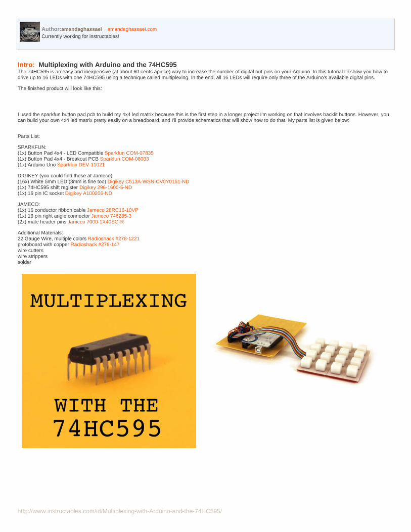
Intro: Multiplexing with Arduino and the 74HC595The 74HC595 is an easy and inexpensive (at about 60 cents apiece) way to increase the number of digital out pins on your Arduino. In this tutorial I'll show you how todrive up to 16 LEDs with one 74HC595 using a technique called multiplexing. In the end, all 16 LEDs will require only three of the Arduino's available digital pins.
The finished product will look like this:
I used the sparkfun button pad pcb to build my 4x4 led matrix because this is the first step in a longer project I'm working on that involves backlit buttons. However, youcan build your own 4x4 led matrix pretty easily on a breadboard, and I'll provide schematics that will show how to do that. My parts list is given below:
Parts List:
SPARKFUN:(1x) Button Pad 4x4 - LED Compatible Sparkfun COM-07835(1x) Button Pad 4x4 - Breakout PCB Sparkfun COM-08033(1x) Arduino Uno Sparkfun DEV-11021
DIGIKEY (you could find these at Jameco):(16x) White 5mm LED (3mm is fine too) Digikey C513A-WSN-CV0Y0151-ND(1x) 74HC595 shift register Digikey 296-1600-5-ND(1x) 16 pin IC socket Digikey A100206-ND
JAMECO:(1x) 16 conductor ribbon cable Jameco 28RC16-10VP(1x) 16 pin right angle connector Jameco 746285-3(2x) male header pins Jameco 7000-1X40SG-R
Additional Materials:22 Gauge Wire, multiple colors Radioshack #278-1221protoboard with copper Radioshack #276-147wire cutterswire stripperssolder

http://www.instructables.com/id/Multiplexing-with-Arduino-and-the-74HC595/
Step 1: What Is Multiplexing?Multiplexing is a very efficient technique for controlling many components wired together in a matrix/array. In this example, I'll be talking exclusively about multiplexing anarray of LEDs, but the same basic principles apply to other multiplexed components (sensors, buttons, etc).
In a multiplexed array of LEDs, only one row of LEDs is on at any given time. It seems like this would limit the types of shapes we can display on the LED matrix, but itactually doesn't. This is because the arduino (or whatever is sending data to the array) is switching through each row so quickly (hundreds or thousands of times asecond) that we do not perceive the flashing on and off of each consecutive row. You can read more about this phenomenon, called persistence of vision , on wikipedia.
So how do we send data to one row at a time? If we connect five volts (red) to one row and connect ground (blue) to the other three rows and cycle through each row oneby one, it will look something like figure 1. Now image that while one of the rows is at +5, we connect one of the columns to ground. As shown in figure 2, this will causethe LED at the junction of the +5 row and GND column to light up. This way, we can address each of the 16 LEDs in the matrix individually using only eight leads (four tothe rows and four to the columns).
Now look at the image below. Imagine if we very quickly turn on the LED in the upper left corner (position 1,1), then the LED at (2,2), then (3,3) and (4,4), and we cyclebetween these four LEDs very quickly (hundreds of times a second). It will appear that all four of these LEDs are on a the same time (as shown in right image in theimage below). Study the diagram below and convince yourself that this is true.
http://www.instructables.com/id/Multiplexing-with-Arduino-and-the-74HC595/
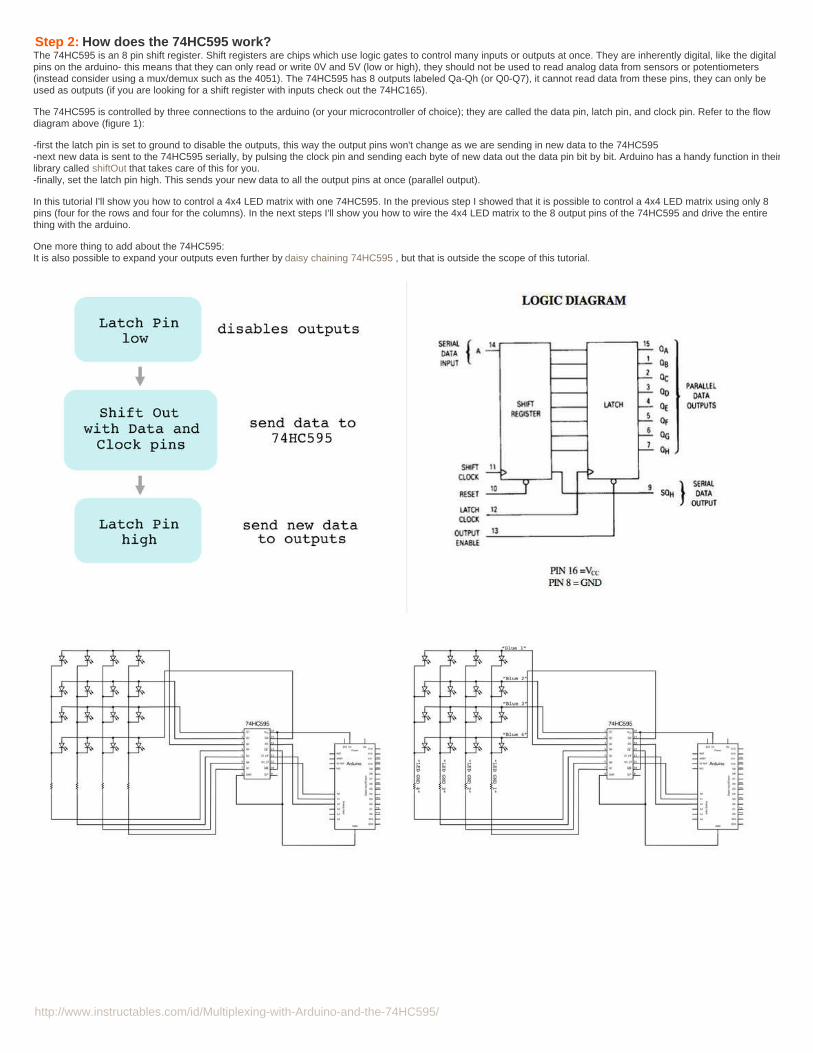
Step 2: How does the 74HC595 work?The 74HC595 is an 8 pin shift register. Shift registers are chips which use logic gates to control many inputs or outputs at once. They are inherently digital, like the digitalpins on the arduino- this means that they can only read or write 0V and 5V (low or high), they should not be used to read analog data from sensors or potentiometers(instead consider using a mux/demux such as the 4051). The 74HC595 has 8 outputs labeled Qa-Qh (or Q0-Q7), it cannot read data from these pins, they can only beused as outputs (if you are looking for a shift register with inputs check out the 74HC165).
The 74HC595 is controlled by three connections to the arduino (or your microcontroller of choice); they are called the data pin, latch pin, and clock pin. Refer to the flowdiagram above (figure 1):
-first the latch pin is set to ground to disable the outputs, this way the output pins won't change as we are sending in new data to the 74HC595-next new data is sent to the 74HC595 serially, by pulsing the clock pin and sending each byte of new data out the data pin bit by bit. Arduino has a handy function in theirlibrary called shiftOut that takes care of this for you.-finally, set the latch pin high. This sends your new data to all the output pins at once (parallel output).
In this tutorial I'll show you how to control a 4x4 LED matrix with one 74HC595. In the previous step I showed that it is possible to control a 4x4 LED matrix using only 8pins (four for the rows and four for the columns). In the next steps I'll show you how to wire the 4x4 LED matrix to the 8 output pins of the 74HC595 and drive the entirething with the arduino.
One more thing to add about the 74HC595:It is also possible to expand your outputs even further by daisy chaining 74HC595 , but that is outside the scope of this tutorial.
http://www.instructables.com/id/Multiplexing-with-Arduino-and-the-74HC595/
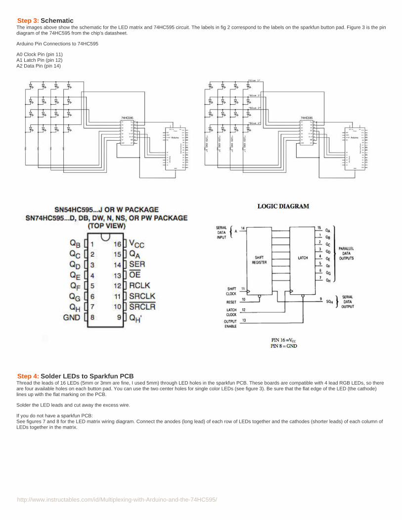
Step 3: SchematicThe images above show the schematic for the LED matrix and 74HC595 circuit. The labels in fig 2 correspond to the labels on the sparkfun button pad. Figure 3 is the pindiagram of the 74HC595 from the chip's datasheet.
Arduino Pin Connections to 74HC595
A0 Clock Pin (pin 11)A1 Latch Pin (pin 12)A2 Data Pin (pin 14)
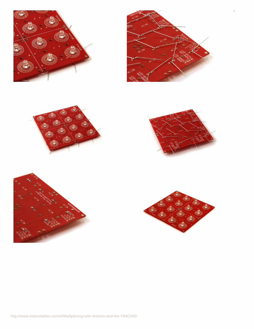
Step 4: Solder LEDs to Sparkfun PCBThread the leads of 16 LEDs (5mm or 3mm are fine, I used 5mm) through LED holes in the sparkfun PCB. These boards are compatible with 4 lead RGB LEDs, so thereare four available holes on each button pad. You can use the two center holes for single color LEDs (see figure 3). Be sure that the flat edge of the LED (the cathode)lines up with the flat marking on the PCB.
Solder the LED leads and cut away the excess wire.
If you do not have a sparkfun PCB:See figures 7 and 8 for the LED matrix wiring diagram. Connect the anodes (long lead) of each row of LEDs together and the cathodes (shorter leads) of each column ofLEDs together in the matrix.
http://www.instructables.com/id/Multiplexing-with-Arduino-and-the-74HC595/
http://www.instructables.com/id/Multiplexing-with-Arduino-and-the-74HC595/
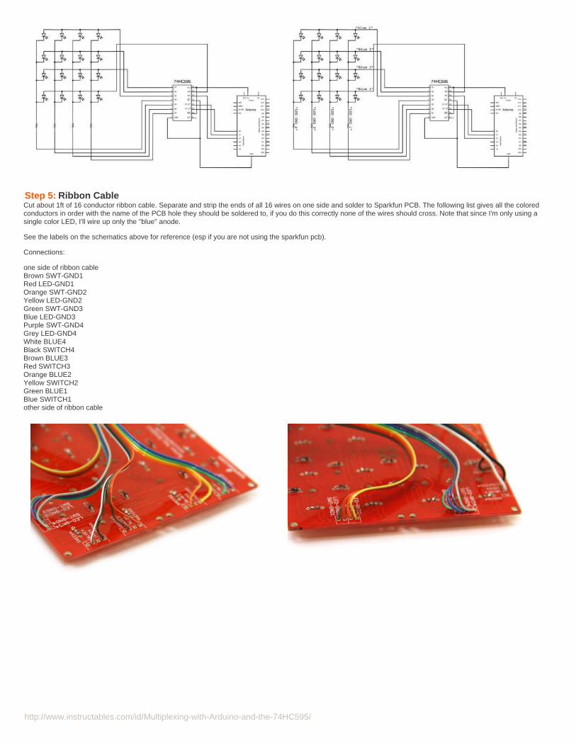
Step 5: Ribbon CableCut about 1ft of 16 conductor ribbon cable. Separate and strip the ends of all 16 wires on one side and solder to Sparkfun PCB. The following list gives all the coloredconductors in order with the name of the PCB hole they should be soldered to, if you do this correctly none of the wires should cross. Note that since I'm only using asingle color LED, I'll wire up only the "blue" anode.
See the labels on the schematics above for reference (esp if you are not using the sparkfun pcb).
Connections:
one side of ribbon cableBrown SWT-GND1Red LED-GND1Orange SWT-GND2Yellow LED-GND2Green SWT-GND3Blue LED-GND3Purple SWT-GND4Grey LED-GND4White BLUE4Black SWITCH4Brown BLUE3Red SWITCH3Orange BLUE2Yellow SWITCH2Green BLUE1Blue SWITCH1other side of ribbon cable
http://www.instructables.com/id/Multiplexing-with-Arduino-and-the-74HC595/
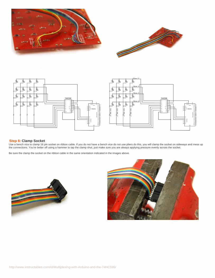
Step 6: Clamp SocketUse a bench vice to clamp 16 pin socket on ribbon cable. If you do not have a bench vice do not use pliers do this, you will clamp the socket on sideways and mess upthe connections. You're better off using a hammer to tap the clamp shut, just make sure you are always applying pressure evenly across the socket.
Be sure the clamp the socket on the ribbon cable in the same orientation indicated in the images above.
http://www.instructables.com/id/Multiplexing-with-Arduino-and-the-74HC595/
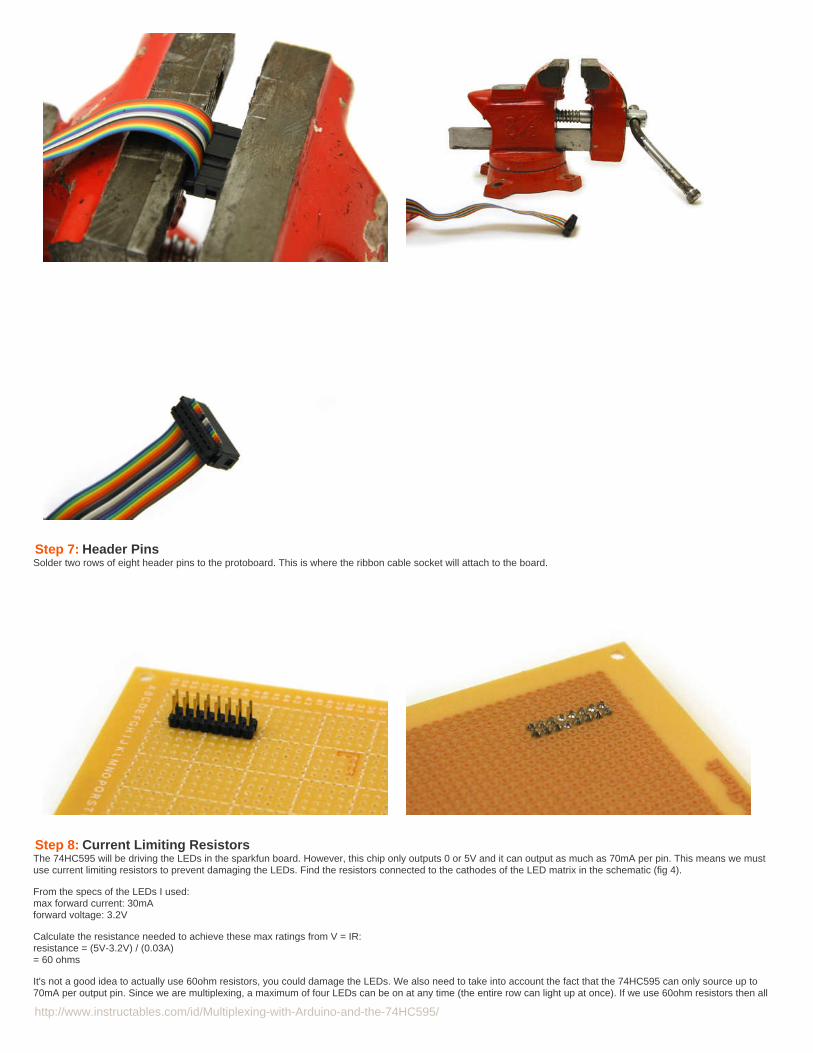
Step 7: Header PinsSolder two rows of eight header pins to the protoboard. This is where the ribbon cable socket will attach to the board.
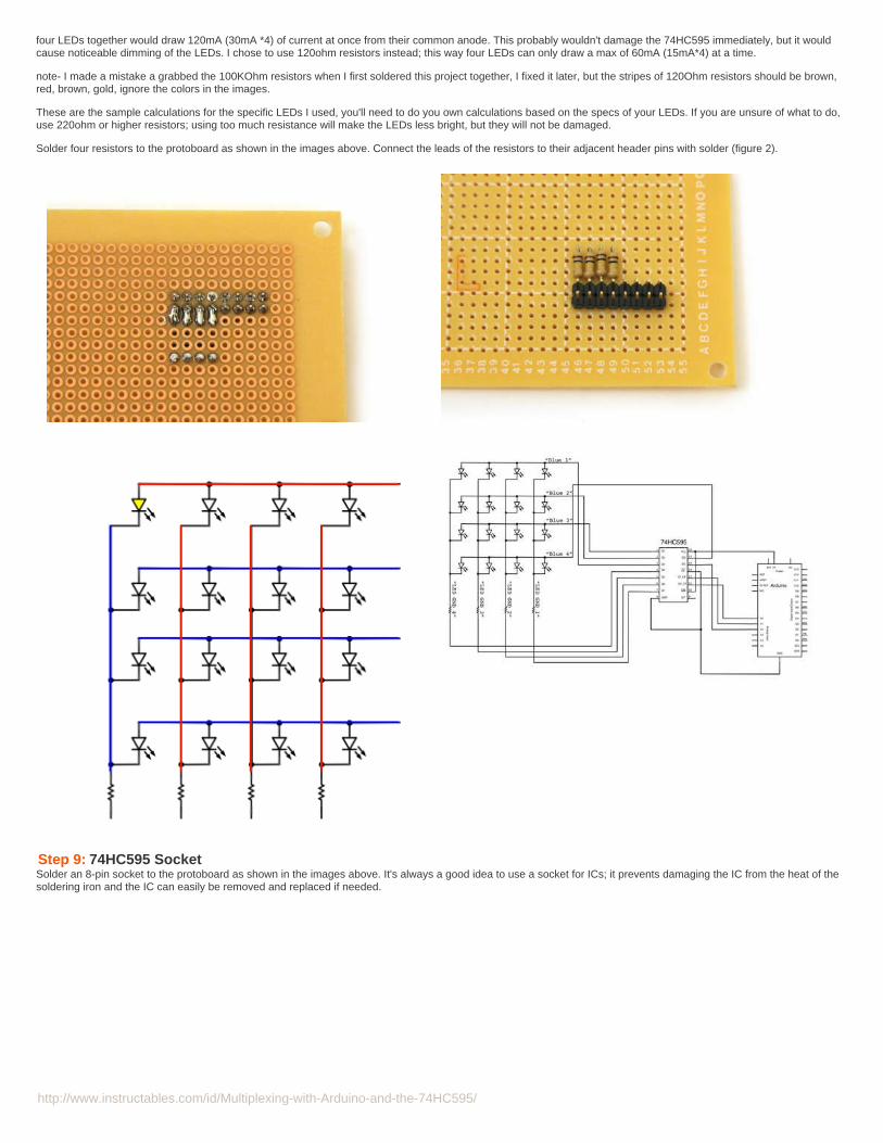
Step 8: Current Limiting ResistorsThe 74HC595 will be driving the LEDs in the sparkfun board. However, this chip only outputs 0 or 5V and it can output as much as 70mA per pin. This means we mustuse current limiting resistors to prevent damaging the LEDs. Find the resistors connected to the cathodes of the LED matrix in the schematic (fig 4).
From the specs of the LEDs I used:max forward current: 30mAforward voltage: 3.2V
Calculate the resistance needed to achieve these max ratings from V = IR:resistance = (5V-3.2V) / (0.03A)= 60 ohms
It's not a good idea to actually use 60ohm resistors, you could damage the LEDs. We also need to take into account the fact that the 74HC595 can only source up to70mA per output pin. Since we are multiplexing, a maximum of four LEDs can be on at any time (the entire row can light up at once). If we use 60ohm resistors then all
http://www.instructables.com/id/Multiplexing-with-Arduino-and-the-74HC595/
four LEDs together would draw 120mA (30mA *4) of current at once from their common anode. This probably wouldn't damage the 74HC595 immediately, but it wouldcause noticeable dimming of the LEDs. I chose to use 120ohm resistors instead; this way four LEDs can only draw a max of 60mA (15mA*4) at a time.
note- I made a mistake a grabbed the 100KOhm resistors when I first soldered this project together, I fixed it later, but the stripes of 120Ohm resistors should be brown,red, brown, gold, ignore the colors in the images.
These are the sample calculations for the specific LEDs I used, you'll need to do you own calculations based on the specs of your LEDs. If you are unsure of what to do,use 220ohm or higher resistors; using too much resistance will make the LEDs less bright, but they will not be damaged.
Solder four resistors to the protoboard as shown in the images above. Connect the leads of the resistors to their adjacent header pins with solder (figure 2).
Step 9: 74HC595 SocketSolder an 8-pin socket to the protoboard as shown in the images above. It's always a good idea to use a socket for ICs; it prevents damaging the IC from the heat of thesoldering iron and the IC can easily be removed and replaced if needed.

http://www.instructables.com/id/Multiplexing-with-Arduino-and-the-74HC595/
Step 10: Connections to LEDsThe output pins (Qa-Qh) are located on pins 1-7 and 15 of the 74HC595. Connect the resistors to pins 4-7 with jumper wires as shown in figures 1 and 2. Connect themale header pins to pins 1-3 and 15 as indicated in figs 3 and 4 (see the note on the image- I made a mistake while soldering, refer to schematic and info below forproper wiring). Make sure to electrically join all these connections with solder on the underside of the board (figs 2 and 4).
As indicated in the schematic, the pin connections are as follows:
toprow 1 (or "blue 1") QD(3)row 2 (or "blue 2") QC(2)row 3 (or "blue 3") QB(1)row 4 (or "blue 4") QA(15)bottom
left (if you are facing the front of display/looking into the LEDs)column 1 (or "led gnd 4") QH(7)column 2 (or "led gnd 3") QG(6)column 3 (or "led gnd 2") QF(5)column 4 (or "led gnd 1") QE(4)right

http://www.instructables.com/id/Multiplexing-with-Arduino-and-the-74HC595/
Image Notes1. these connections should be reversed- I made a mistake while soldering
Step 11: ArduinoSolder header pins to breadboard so that Arduino Uno will snap to the board. You may need to bend some of the header pins with pliers to get a good fit (fig 1).
Connect the three 74HC595 data pins to arduino analog in 0, 1, and 2 according to the schematic. Connect pins 8 and 13 of the 74HC595 to arduino ground and pins 10and 16 of the 74HC595 to Arduino 5V.
Arduino Pin Connections to 74HC595
A0 Clock Pin (pin 11)A1 Latch Pin (pin 12)A2 Data Pin (pin 14)
Image Notes1. pins to digital pins 8-13 were bent for better fit
http://www.instructables.com/id/Multiplexing-with-Arduino-and-the-74HC595/
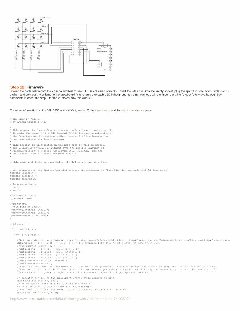
Step 12: FirmwareUpload the code below onto the arduino and test to see if LEDs are wired correctly. Insert the 74HC595 into the empty socket, plug the sparkfun pcb ribbon cable into itssocket, and connect the arduino to the protoboard. You should see each LED light up one at a time, this loop will continue repeating forever (see video below). Seecomments in code and step 3 for more info on how this works.
For more information on the 74HC595 and shiftOut, see fig 2, the datasheet , and the arduino reference page .
//LED TEST w/ 74HC595//by Amanda Ghassaei 2012
/** This program is free software; you can redistribute it and/or modify* it under the terms of the GNU General Public License as published by* the Free Software Foundation; either version 2 of the License, or* (at your option) any later version.** This program is distributed in the hope that it will be useful,* but WITHOUT ANY WARRANTY; without even the implied warranty of* MERCHANTABILITY or FITNESS FOR A PARTICULAR PURPOSE. See the* GNU General Public License for more details.*/
//this code will light up each led in the 4x4 matrix one at a time
//pin connections- the #define tag will replace all instances of "latchPin" in your code with A1 (and so on)#define latchPin A1#define clockPin A0#define dataPin A2
//looping variablesbyte i;byte j;
//storage variablebyte dataToSend;
void setup() { //set pins as output pinMode(latchPin, OUTPUT); pinMode(clockPin, OUTPUT); pinMode(dataPin, OUTPUT);}
void loop() {
for (i=0;i<4;i++){
for (j=0;j<4;j++){
//bit manipulation (more info at http://arduino.cc/en/Reference/Bitshift , http://arduino.cc/en/Reference/BitwiseXorNot , and http://arduino.cc/en/Reference/BitwiseAnd) dataToSend = (1 << (i+4)) | (15 &~(1 << j));//preprare byte (series of 8 bits) to send to 74HC595 //for example when i =2, j = 3, //dataToSend = (1 << 6) | (15 &~(1 << 3)); //dataToSend = 01000000 | (15 &~(00001000)); //dataToSend = 01000000 | (15 &11110111); //dataToSend = 01000000 | (15 &11110111); //dataToSend = 01000000 | 00000111; //dataToSend = 01000111; //the first four bits of dataToSend go to the four rows (anodes) of the LED matrix- only one is set high and the rest are set to ground //the last four bits of dataToSend go to the four columns (cathodes) of the LED matrix- only one is set to ground and the rest are high //this means that going through i = 0 to 3 and j = 0 to three with light up each led once
// setlatch pin low so the LEDs don't change while sending in bits digitalWrite(latchPin, LOW); // shift out the bits of dataToSend to the 74HC595 shiftOut(dataPin, clockPin, LSBFIRST, dataToSend); //set latch pin high- this sends data to outputs so the LEDs will light up digitalWrite(latchPin, HIGH);

http://www.instructables.com/id/Multiplexing-with-Arduino-and-the-74HC595/
delay(500);//wait } }
}
Step 13: More FirmwareThe previous code was a good example of how to address each led one at a time, I slowed down the speed that the 74HC595 cycles through each pin so that you canreally see each led by itself. But the real purpose of multiplexing is to cycle through each row very quickly and address the whole matrix at once.
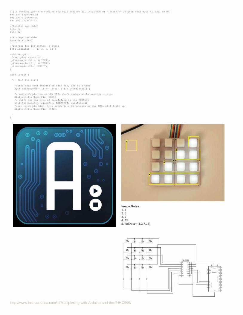
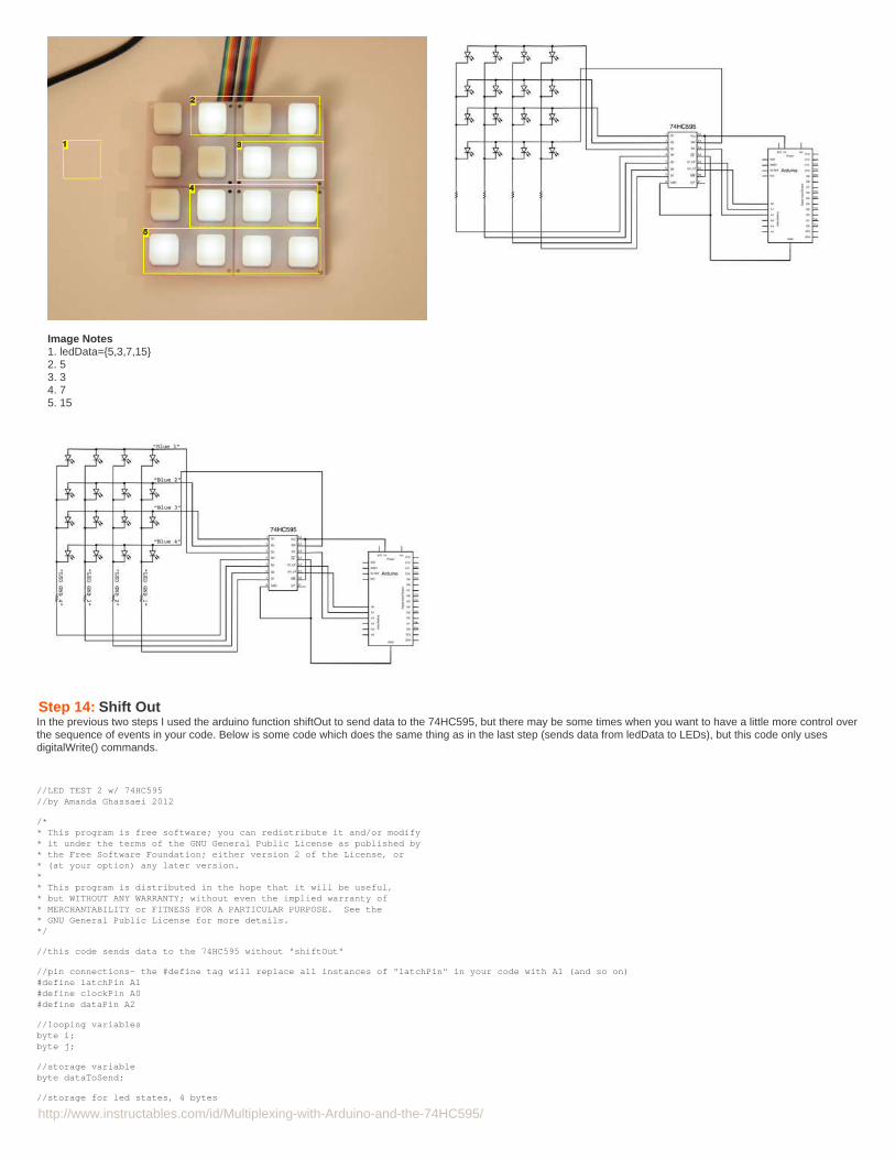
In the code below, I set up the array "ledData". Each number in ledData corresponds to a row of LEDs in the 4x4 matrix. The first number (by default 1) corresponds tothe top row, the second number (by default 3) to the second row, and so on.... The values in ledData can range from 0 - 15, where 0 is all LEDs off in that row and 15 isall LEDs on in that row. You can get any combination of off and on LEDs by finding its binary equivalent and storing this value in the array ledData. The default values inledData will generate the pattern shown in figure 2. Try changing the defaults and see the results, by changing ledData to {5,3,7,15} I generated the pattern shown infigure 3.
//LED TEST 2 w/ 74HC595//by Amanda Ghassaei 2012
/** This program is free software; you can redistribute it and/or modify* it under the terms of the GNU General Public License as published by* the Free Software Foundation; either version 2 of the License, or* (at your option) any later version.** This program is distributed in the hope that it will be useful,* but WITHOUT ANY WARRANTY; without even the implied warranty of* MERCHANTABILITY or FITNESS FOR A PARTICULAR PURPOSE. See the* GNU General Public License for more details.*/
//this code will display the values of ledData across a 4x4 led matrix
http://www.instructables.com/id/Multiplexing-with-Arduino-and-the-74HC595/
//pin connections- the #define tag will replace all instances of "latchPin" in your code with A1 (and so on)#define latchPin A1#define clockPin A0#define dataPin A2
//looping variablesbyte i;byte j;
//storage variablebyte dataToSend;
//storage for led states, 4 bytesbyte ledData[] = {1, 3, 7, 15};
void setup() { //set pins as output pinMode(latchPin, OUTPUT); pinMode(clockPin, OUTPUT); pinMode(dataPin, OUTPUT);}
void loop() {
for (i=0;i<4;i++){
//send data from ledData to each row, one at a time byte dataToSend = (1 << (i+4)) | (15 &~ledData[i]);
// setlatch pin low so the LEDs don't change while sending in bits digitalWrite(latchPin, LOW); // shift out the bits of dataToSend to the 74HC595 shiftOut(dataPin, clockPin, LSBFIRST, dataToSend); //set latch pin high- this sends data to outputs so the LEDs will light up digitalWrite(latchPin, HIGH);
}}
Image Notes1. 12. 33. 74. 155. ledData= {1,3,7,15}
http://www.instructables.com/id/Multiplexing-with-Arduino-and-the-74HC595/
Image Notes1. ledData={5,3,7,15}2. 53. 34. 75. 15
Step 14: Shift OutIn the previous two steps I used the arduino function shiftOut to send data to the 74HC595, but there may be some times when you want to have a little more control overthe sequence of events in your code. Below is some code which does the same thing as in the last step (sends data from ledData to LEDs), but this code only usesdigitalWrite() commands.
//LED TEST 2 w/ 74HC595//by Amanda Ghassaei 2012
/** This program is free software; you can redistribute it and/or modify* it under the terms of the GNU General Public License as published by* the Free Software Foundation; either version 2 of the License, or* (at your option) any later version.** This program is distributed in the hope that it will be useful,* but WITHOUT ANY WARRANTY; without even the implied warranty of* MERCHANTABILITY or FITNESS FOR A PARTICULAR PURPOSE. See the* GNU General Public License for more details.*/
//this code sends data to the 74HC595 without "shiftOut"
//pin connections- the #define tag will replace all instances of "latchPin" in your code with A1 (and so on)#define latchPin A1#define clockPin A0#define dataPin A2
//looping variablesbyte i;byte j;
//storage variablebyte dataToSend;
//storage for led states, 4 bytes

http://www.instructables.com/id/Multiplexing-with-Arduino-and-the-74HC595/
byte ledData[] = {1, 3, 7, 15};
void setup() { //set pins as output pinMode(latchPin, OUTPUT); pinMode(clockPin, OUTPUT); pinMode(dataPin, OUTPUT);}
void loop() {
for (i=0;i<4;i++){
//send data from ledData to each row, one at a time byte dataToSend = (1 << (i+4)) | (15 &~ledData[i]);
// setlatch pin low so the LEDs don't change while sending in bits digitalWrite(latchPin, LOW);
// // shift out the bits of dataToSend to the 74HC595// shiftOut(dataPin, clockPin, LSBFIRST, dataToSend);// the code below is the equivalent of the two lines above for (j=0;j<8;j++){ digitalWrite(clockPin,LOW); digitalWrite(dataPin,((dataToSend>>j)&)); digitalWrite(clockPin,HIGH); }
//set latch pin high- this sends data to outputs so the LEDs will light up digitalWrite(latchPin, HIGH);
}}
Related Instructables
How to use a74HC595 ShiftRegister with aAVR ATtiny13by roznerd
8 LED Chaserwith 74HC595 8Bit ShiftRegister byDominion-Network
Make a 8x10L.E.D Matrix bySyst3mX
LCD Shifter forArduino byGusPS
LED BinaryCalculator bySyst3mX
The BlokClokConcept -Arduino drivenRGB AbstractClock (video) byearthshine