· osi layers 4 to 7, one of which is the isdn user part (isup) that ... report that failure to...
TRANSCRIPT


On the Use of SCTP in Failover-Scenarios
Andreas Jungmaier, Erwin P. RathgebComputer Networking Technology Group,
IEM, University of EssenEllernstr. 29, 45326 Essen, Germany
Michael TuxenICN WN CC SE 7, Siemens AG,
Hofmannstr. 51, 81359 Munich, Germany
ABSTRACT
The new general purpose transport protocol SCTP (Stream Con-trol Transmission Protocol) has been developed for transport ofsignaling data, such as Signaling System No. 7 MTP level 2 or 3user primitives, over IP networks. Since this application has espe-cially high requirements towards the underlying transport proto-col concerning reliability and fast recognition and recovery fromfailures, SCTP-based transmission must provide a high degree ofnetwork level fault tolerance. In our contribution we look at a typ-ical link failure scenario in a multi-homed setup, and investigatetwo options for fast recovery from such an event, namely seam-less SCTP switch-over, and a user level switch-over as has beensuggested for the MTP Level 2 peer adaptation layer. Moreover,we will analyze necessary parameter settings for fast recoveryfrom the failure situation.1
Keywords: Transport Protocol, Stream Control TransmissionProtocol, Failover, Signaling System No. 7, MTP Level 2
1. INTRODUCTION
As a consequence of the steady growth of the integrated servicesdigital network (ISDN) and the introduction of new cellular net-works and services such as GPRS (General Packet Radio Service)and UMTS (Universal Mobile Telecommunications System) theunderlying network infrastructures must provide enhanced sup-port for voice, data and multimedia services. For useful andeconomically sound overall solutions, cooperation among ISDN-based, and newer, IP-based infrastructures is a key issue. Thetrend of convergence between these different technologies neces-sitates that signaling transport can also be provided via pure IPbased networks with the required reliability and performance.Therefore, a corresponding protocol suite has been defined inthe Signaling Transport (SIGTRAN) working group of the In-ternet Engineering Task Force (IETF). The basis of this suite isthe Stream Control Transmission Protocol (SCTP), an end-to-endprotocol for reliable data transport via IP networks. On top of thisprotocol, a number of adaptation layers have been defined fortransport of Signaling System No. 7 primitives (cf. section 2.).
1Acknowledgement: This work was partially funded by the Bun-desministerium fur Bildung und Forschung (BMBF) of the Federal Re-public of Germany (Forderkennzeichen 01AK045). The authors aloneare responsible for the content of the paper.
2. THE SIGNALING SYSTEM NO. 7
The ISDN protocol reference model separates the functions usedfor user data transfer (User Plane) from those used for controllingthe network and the user data channels (Control Plane). To ex-change signalling information between the user terminals and thelocal exchange, the Digital Subscriber Signaling System No. 1(DSS1) is used, whereas the transfer of signaling informationamong the switches within the network is performed by usingthe Signaling System No. 7 (SS7)[5]. This architecture leads tothe definition of logically separate networks for user data (typ-ically 64 kbit/s channels) and for signaling information (packetoriented).
Figure 1 shows the basic protocol architecture of a SS7 net-work. The functions related to the transfer of signaling messagesare handled by the Message Transfer Part (MTP) protocols [6].The MTP Level 1 (MTP1) provides signalling data link functionstypical for OSI layer 1. MTP Level 2 (MTP2) provides a HDLC-like data link protocol (OSI layer 2) with enhancements relatedto fast discovery of link failures and reliability. MTP Level 3(MTP3) provides a simple packet oriented connectionless service– a subset of OSI layer 3 – and management function for the sig-naling network and its links. The basic transfer capability of theMTP is used by various user parts implementing functions of theOSI layers 4 to 7, one of which is the ISDN User Part (ISUP) thatmanages circuit switched ISDN user connections.
The Signaling Control Connection Control Part (SCCP) ex-tends the MTP to the full functionality of an OSI NSAP (Net-work Service Access Point) by providing, e.g. a connection ori-ented service. SCCP is commonly used in combination withthe so-calledTransaction Capabilities(TC) in order to providetransaction oriented services to various applications, includingSystem Management (SMAP), mobility management for cellu-lar networks, or the Intelligent Network (IN).
2.1 LINKSETS
The nodes in the SS7 network are called signaling points (SP)and are connected by signaling links, the bandwidth of which istypically 64 kbit/s. There can be up to 16 links that may be usedbetween any two SPs which is referred to as a linkset. This isdone for two reasons:
1. Multiple links in a linkset may be used to provide the nec-essary bandwidth by using a loadsharing algorithm. For adetailed discussion of this topic see [4].
363

Appl. forMobilityManagem. and IN
Signaling Link Functions
Signaling Network Functions
Signaling Data Link Functions
ApplicationPrograms forCall Control
OSI Layer CCS7 Level
3
4,5,6
7
2
1
4
1
2
3
MTP
ASEs
SMAP
OMAP
ISUPTCAP
ISP
TC
SCCP Parts
OtherUser
Application Part
Terminology
OSI Open Systems
PartTCAP Transaction Capabilities
SCCP Signaling Connection
MTP Message Transfer Part
CCS7 Common Channel Signaling System No.7
Interconnection
Control Part
TC Transaction Capabilities
ISP Intermediate Service
Application ProcessSMAP Systems Management
OMAP Operation,Maintenance & Administration Part
Element ASE Application Service
Figure 1: SS7 protocol architecture
2. Multiple links may be used to provide redundancy. If onelink fails, the traffic is distributed to the other links in thelinkset.
This contribution will focus on the second aspect. If, in a linksetwith two links, one link fails, the following actions take place:
1. MTP2 of the the failed link informs MTP3 of the SP aboutfailure.
2. MTP3 of the SP recovers all messages from MTP2 of thefailed link which have not been successfully delivered tothe peer SP.
3. MTP3 of the SP resends all those messages to the peer usingthe second link.
This procedure is called change-over and is designed to minimizepacket loss and missequencing of signalling messages in case ofa link failure. [7] requires that the change-over procedure doestake no longer than 800 ms.
2.2 RELIABILITY REQUIREMENTS OF SS7NETWORKS
An SS7 network is the most sensitive part of the ISDN networkand, therefore, has to fulfill strict reliability requirements. Theseare specified in [7] and include the following:
• Not more than one in107 messages may be lost due to fail-ure in the MTP.
• Not more than one in1010 messages may be delivered out-of-sequence to the user parts due to failure in the MTP. Thisalso includes duplication of messages.
• The availability of any signaling relation (i.e. between SPsthat originate and consume signaling messages) has to beat least 0.99998 corresponding to a downtime of at most 10minutes/year.
3. IP-BASED SIGNALING TRANSPORT
The Signaling Transport working group of the IETF has de-scribed the general architecture of IP-based signaling transportin [2]. In these scenarios messages of different MTP levels aretransported via an adapation layer (specific to the concerned MTPlevel) on top of a SCTP association. Most of these SCTP adap-tation layers provide the ability to connect IP-based devices run-ning onlyupper layersof the SS7 protocol stack to the SS7 net-work. These devices are connected to so called Signaling Gate-ways (SGs) which are connected to both the SS7 network and anIP-based network. A Signaling Gateway runs the lower layers ofthe SS7 protocol stack. These solutions are typically asymmetric.
3.1 SS7 MTP2 PEER ADAPTATION LAYER
The SS7 MTP2 Peer Adapation Layer (M2PA) currently beingdefined in [3] provides an IP-based signaling link. There is nostrict bandwidth limitation like in the case of typical (narrow-band) signaling links. Therefore M2PA conveniently providesbroadband IP-based signaling links, used in a symmetric way.Figure 2 shows the protocol stacks involved in a M2PA architec-ture between two Signaling Gateways.
M2PASCTP
IP
M2PASCTP
IP
Signaling GatewaySignaling Gateway
SS7 networkIP based networkSS7 network
MTP 2
MTP 1
MTP 2
MTP 1
MTP 3 MTP 3
Figure 2: Protocol stacks used for M2PA based communi-cation
364

3.2 THE STREAM CONTROL TRANSMISSIONPROTOCOL
SCTP, as defined in [1], is a message-oriented, reliable trans-port protocol, explicitly supporting multi-homed endpoints, i.e.endpoints with more than one IP address. Contrary to TCP, theSCTP send- and receive-primitives will preserve message bound-aries. The protocol can multiplex several short messages into oneSCTP packet, which is subsequently transmitted as payload ofone IP packet.
SCTP provides its user with a very flexible method of datadelivery by separating the reliable transfer of messages betweenendpoints (ensured by proper use of transmission sequence num-bers, acknowledgements and retransmission timers) from the ac-tual delivery to the user process which is performed in so-calledstreams. Streams refer to a sequence of messages usually deliv-ered in order. This is achieved at the cost of having additionalstream sequence numbers used for this end.
Due to the complex effects of multi-homing and routing, themulti-homing feature as such neither guarantees the reachabil-ity of an endpoint nor does it guarantee a higher availabilty incase of network failures. In a carefully engineered network setuphowever, or in an internet setting with connectivity to more thanone internet service provider (ISP), a protocol supporting multi-homing greatly improves network level fault tolerance.
3.3 PATH AND PEER MONITORING
For an SCTP endpoint, the notion of a path is equal to that ofone peer destination address. By default, SCTP endpoints mon-itor the reachability of their peers as well as availability of eachpath to the peer by regularly sending heartbeat messages to all ofthe destination addresses of the peer endpoint. Upon receptionof such a message, an endpoint is bound to reply with a heart-beat acknowledgment message. An SCTP endpoint keeps trackof the number of consecutive retransmissions of data or heartbeatmessages sent to the peer endpoint (increasing the association er-ror counter), respectively to each path (increasing the respectivepath error counter). Each time a chunk is acknowledged, the rel-evant counter is cleared. Once it exceeds an error limit, the peerendpoint or the concerned path is considered unavailable.
3.4 PATH SELECTION
In a multi-homed SCTP association, one path is selected as theprimary pathand carries the main load of the user data trans-mission. Other paths are only used for data retransmissions andheartbeat messages. Should the primary path become unreach-able, an endpoint may send data to another, active address andreport that failure to its user which can subsequently choose anew primary path.
4. INVESTIGATION OF FAILOVER SCENARIOS
In section 2.1 it was noted that multiple links provide the neces-sary redundancy required for SS7 networks. The same require-ments have to be fulfilled by M2PA-based communication. ForM2PA there are two ways to provide redundancy:
1. The MTP3 has only one link, and the M2PA relies on itslower layer for providing redundancy. Therefore, one SCTP
association uses multi-homed hosts. In case of network fail-ures the built-in features of SCTP will be used to handle thefailure.
2. Two SCTP associations will be used and the MTP3 has twolinks. The normal change-over procedure is used in caseof network failures, and M2PA relies on its upper layer forproviding redundancy. Thus, the SCTP associations neednot provide redundancy, and are single-homed.
4.1 DESCRIPTION OF THE LAB SETUP
We investigated the parameters for optimizing the change-overbehaviour in a lab environment where an SCTP user applicationmimicks MTP3 by generating traffic and reacting to a link fail-ure accordingly. Endpoint A sends data to endpoint B and thelink carrying the main data load experiences a link failure. Onescenario, motivated by section 3., uses one dual-homed SCTP as-sociation (see also fig. 4) while the other uses two distinct, single-homed associations (cf. scenario 2, fig. 5).
Both endpoints are connected by a router equipped with aWAN emulator, that emulates link delays between IP address A1and B1, A2 and B2 respectively, of 10 ms, and a bandwidth re-striction for these links of 2.048 MBit/s. The SCTP user appli-cation generates an exponentially distributed traffic pattern witha mean message arrival rate of 100 messages of 500 bytes lengthper second. Furthermore, it reacts to link failures accordingly.
These parameters were chosen to emulate an environmentwhere an IP/SCTP/M2PA-based signaling endpoint is connectedto a signaling gateway that is not located far away from the SEP(say less than 100 km). For a simple IP network with few hops,the chosen link delay time is then appropriate.
The presented results are based on a prototype SCTP imple-mentation that has been realized in cooperation between the Uni-versity of Essen and Siemens AG, Munich and is freely availableunder the GNU Public License fromhttp://www.sctp.de .
4.2 FAILOVER WITH MULTI-HOMING
IP A2
IP A1
Association 1 − Path 2
Association 1 − Path 1
IP B2
IP B1
WAN Emulator
Figure 4: Investigated scenario 1 - one dual-homed associ-ation
At the time of failure, the SCTP protocol will experience trans-mission timer timeout events, and retransmit data onto the secondpath. New data will be transmitted to the failed path, and after awhile be retransmitted on the second. After the error counter forthe failed path has been exceeded, the path is reported unreach-able and the user makes the second path new primary. At thattime, retransmissions and new transmissions will use the second
365
0
100
200
300
400
500
600
700
-500 0 500 1000 1500
Mes
sage
Del
ay [
ms]
Time (ms)
Message Delays: Absolute Values and Moving Average(RTOmin 40ms, PRL=4, RTOmax 200ms)
Moving Average (10 values)Single Messages
0
100
200
300
400
500
600
700
0 500 1000 1500
Mes
sage
Del
ay [
ms]
Time (ms)
Message Delays: Absolute Values and Moving Average(RTOmin 40ms, PRL=4, RTOmax 200ms)
Moving Average (10 values)Single Messages
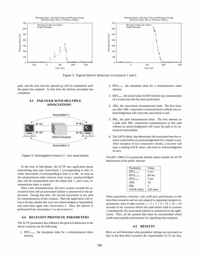
Figure 3: Typical failover behaviour in scenarios 1 and 2
path, and the data that has queued up will be transmitted untilthe queue has emptied. At that time the failover procedure hascompleted.
4.3 FAILOVER WITH MULTIPLEASSOCIATIONS
IP A2
IP A1
Association 2
Association 1
IP B1
IP B2
WAN Emulator
Figure 5: Investigated scenario 2 - two associations
At the time of link-failure, the SCTP user application keepstransmitting data onto Association 1 (corresponding to link 1),while Association 2 (corresponding to link 2) is idle. As soon asthe retransmission timer timeout event occurs, unacknowledgeddata will be retransmitted onto the failed link 1, and a new re-transmission timer is started.
After a few retransmissions, the error counter exceeds the as-sociation limit and an association failure is announced to the ap-plication. During that time, the second association is not usedfor retransmissions in this scenario. Then the application will re-trieve all data chunks that were not acknowledged or transmitted,and send them again onto Association 2. Thus, the failover isperformed from Association 1 to Association 2.
4.4 RELEVANT PROTOCOL PARAMETERS
The SCTP parameters that influence the protocol behaviour in theabove scenarios are the following:
1. RTOmax, the maximum time for a retransmission timertimeout.
2. RTOmin, the minimum time for a retransmission timertimeout.
3. RTOinit, the initial value for RTO (before any measurementof a round-trip time has been performed.
4. ARL, the association retransmission limit. The first time-out after ARL consecutive retransmissions without any ac-knowledgement will cause the association to fail.
5. PRL, the path retransmission limit. The first timeout ona path after PRL consecutive retransmission to this pathwithout an acknowledgement will cause the path to be an-nounced unreachable.
6. The SACK delay, that determines the maximum time the re-ceiver waits before an acknowledgement for a chunk is sent.After reception of two consecutive chunks, a receiver willstop a running SACK timer, and send an acknowledgmentat once.
The RFC 2960 [1] recommends default values suitable for SCTPdeployment in the public internet:
Parameter ValueRTOmin 1 secRTOmax 60 secRTOinit 3 secARL 10PRL 5SACK delay 200 msec
These parameters, however, will yield poor performance in thedescribed scenarios and are not adapted to signaling transport re-quirements, since it takes at least1 + 2 + 4 + 8 + 16 + 32 = 63seconds in our scenarios before the path failure (and in scenario2 subsequently the association failure) is announced to the appli-cation. Then, all the queued data must be retransmitted whichyields unacceptable performance for signalling data transport.
4.5 RESULTS
Here we will determine what parameter settings are necessary sothat in the described scenarios the requirements of [7] are met,
366

0
200
400
600
800
1000
1200
1400
1600
100 150 200 250
Tim
e [m
s]
max. RTO (ms)
800ms LimitFailover Duration (PRL=2)Failover Duration (PRL=3)Failover Duration (PRL=4)Failover Duration (PRL=5)
0
200
400
600
800
1000
1200
1400
1600
100 150 200 250
Tim
e [m
s]
max. RTO (ms)
800ms LimitFailover Duration (ARL=2)Failover Duration (ARL=3)Failover Duration (ARL=4)Failover Duration (ARL=5)
Figure 6: Absolute duration of failover in scenarios 1 and 2 (RTOmin= 40ms)
0
200
400
600
800
1000
1200
100 150 200 250
Tim
e [m
s]
max. RTO (ms)
400 ms limitMax. Message Delay (PRL=2)Max. Message Delay (PRL=3)Max. Message Delay (PRL=4)Max. Message Delay (PRL=5)
0
200
400
600
800
1000
1200
100 150 200 250
Tim
e [m
s]
max. RTO (ms)
400 ms limitMax. Message Delay (ARL=2)Max. Message Delay (ARL=3)Max. Message Delay (ARL=4)Max. Message Delay (ARL=5)
Figure 7: Maximum message delay during the failover (scenarios 1 and 2, RTOmin= 40ms)
namely the failover time be limited to 800 ms. In order to fur-ther judge the system behaviour, we also looked at individual (i.e.maximum) and average delays of messages during the failoverprocedure. The figures 6, 7 and 8 all show confidence intervalsof 99%.
4.5.1 SCENARIO 1 - A DUAL-HOMEDASSOCIATION
After the primary path failure, the receiver gets the first datachunks by sender retransmission on the second path. The senderkeeps transmitting new chunks over the primary path until an-other retransmission timeout occurs. Figure 3 displays the effectsof this behaviour in an example. Queued messages that are re-transmitted have a decreasing delay, and for after each retrans-mission event new chunks queue up. After the failure has beenrecognized, all chunks are being transmitted directly over the sec-ond path, and the original state is achieved when the queue isemptied again.
Figure 7 shows that the maximum delays grow strongly ifa large number of chunks queue up, which effectively happenswhen the time for recognizing the link failure is high (as forPRL=5, RTOmax=200ms, 250ms). For most of the tested param-eters the maximum message delay was well below 400 ms, and
the average delay of messages during the failover below 200 ms.
4.5.2 SCENARIO 2 - TWO SINGLE-HOMEDASSOCIATIONS
As figure 3 shows nicely, after the path failure no chunks are re-ceived until after the link and association failure have been an-nounced. Then all chunks are sent on the second associationwhere the send queue empties quickly, until the average delayof the chunks is back to normal.
Figure 7 shows the maximum message delay for scenario 2.The maximum message delay depends on the time at which thesender determines that the path and consequently the associationhas failed. For low values of RTOmax that is typically slightlylower thanARL · RTOmax. For ARL=2, the delay does notdepend on RTOmax, since the failure is recognized, before theactual RTO value has reached the maximum value. Note thatfor most of the tested parameters the maximum message delayhigher than 400 ms, and the average delay of messages higherthan 200 ms.
367

400
600
800
1000
1200
1400
100 150 200 250
Tim
e [m
s]
max. RTO (ms)
800ms LimitFailover Duration (RTOmin = 20 ms, PRL=4)Failover Duration (RTOmin = 40 ms, PRL=4)Failover Duration (RTOmin = 60 ms, PRL=4)
0
50
100
150
200
250
300
350
400
450
500
100 150 200 250
Tim
e [m
s]
max. RTO (ms)
Max. Message Delay (RTOmin = 20 ms, PRL=4)Max. Message Delay (RTOmin = 40 ms, PRL=4)Max. Message Delay (RTOmin = 60 ms, PRL=4)
Figure 8: Effects of changing the RTOmin parameter: Failover Duration and Maximum Message Delay (Scenario 1)
4.5.3 A COMPARISON OF BOTH SCENARIOS
On the whole, both scenarios can be used to realize sufficientlyfast recovery from a path failure (cf. figure 6). However there aresome distinctions between the two: scenario 1 always allows asmoother transition in that it keeps the average delay per chunkduring the failover period much lower than scenario 2 (often lessthan 50%) due to early and successful retransmissions over thesecond path. Scenario 1 also allows for a sufficiently fast failoverwithin the mandatory 800 ms for a wider range of parameter set-tings, and is therefore recommended.
SCTP protocol mechanisms may cause a slightly later recog-nition of the path failure in scenario 1 since the retransmissiontimer for the failed path 1 is only started again whennewdata istransmitted on this (primary) path. All retransmissions success-fully use the secondary path, where the retransmission timer isstopped, then. In scenario 2 the retransmission timer is restarteddirectly after expiry, since all retransmissions use the same -failed - path.
Nonetheless, the early and successful retransmission over asecondary path improves the failover behaviour compared to sce-nario 2. In our experiments we found that for all relevant param-eter settings (with an overall recovery time lower than 800 ms),scenario 1 had a faster overall recovery compared to scenario 2.
4.5.4 EFFECTS OF THE MINIMUM RTO
Figure 8 shows that by lowering the RTOmin parameter thefailover times as well the maximum message delays can be fur-ther reduced. However, with very low values of RTOmin as-sociations may become more susceptible to early, unwanted re-transmission timer timeouts, and thus retransmissions. Withvery low PRL values this may even result in use of the sec-ondary path before any actual failure has occurred, so it is gen-erally not recommended to lower the RTOmin parameter belowRTOmin,rec = 2 · RTT. These spurious timeouts must also beavoided since they have a negative effect on the protocol through-put.
5. OUTLOOK AND FURTHER WORK
In this contribution we compared two options for handling linkfailures where SCTP is used as transport protocol for IP based
signaling data transmission. We identified and assessed validSCTP parameter settings that make the investigated systems com-ply with requirements for signaling transport within traditionalsignaling networks. Thus we found that in a carefully setup en-vironment the performance of IP/SCTP/M2PA based signalingtransport is sufficient for transport of MTP3 primitives from aSignaling System No. 7 network. Imperative for this is an earlyrecognition of a path failure, so that queueing of large number ofmessages is avoided, and a fast recovery can be achieved. To sys-tematically investigate a larger set of parameters, simulative stud-ies are being prepaired that will allow a more detailed analysis ofoptimal parameters for different and more complex IP-based net-works.
REFERENCES
[1] R. Stewart, Q. Xie et al.: RFC 2960 - Stream Control Trans-mission Protocol, IETF, Network Working Group, October2000.
[2] L. Ong, I. Rytina, M. Garcia et al.: RFC 2719 - FrameworkArchitecture for Signaling Transport, IETF, Network Work-ing Group, October 1999.
[3] T. George et al.: SS7 MTP2-User Peer-to-Peer AdaptationLayer, draft-ietf-sigtran-m2pa-03.txt, Internet Draft, Workin Progress, July 2001.
[4] K. D. Gradischnig, St. Kramer, M. Tuxen: Loadsharing – Akey to the reliability of SS7-networks, DRCN 2000.
[5] ITU-T Recommendation Q.700: Introduction to CCITTSignalling System No. 7, International TelecommunicationUnion, Geneva, March 1993.
[6] ITU-T Recommendation Q.701: Functional descriptionof the message transfer part (MTP) of Signalling SystemNo. 7, International Telecommunication Union, Geneva,March 1993.
[7] ITU-T Recommendation Q.706: Signalling System No. 7– Message Transfer Part Signalling Performance, Interna-tional Telecommunication Union, Geneva, March 1993.
368