quotation · quotation date 7/30/2013 quote # 21920 ... ordered by you is expressly conditioned...
TRANSCRIPT
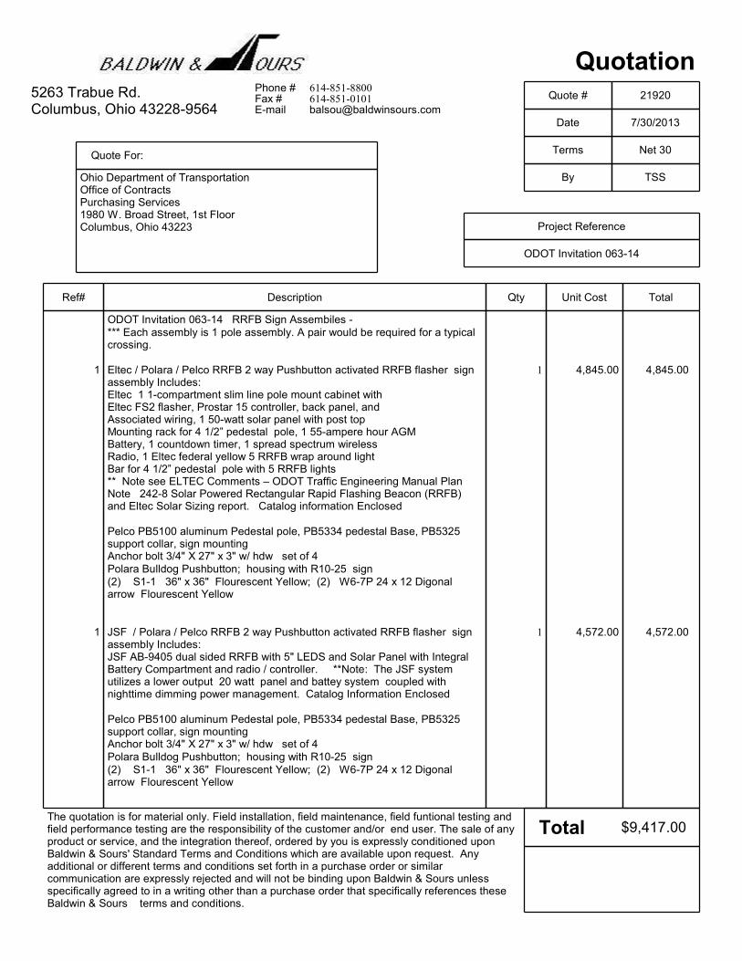
Quotation
Date 7/30/2013
Quote # 21920
Quote For:
Ohio Department of TransportationOffice of ContractsPurchasing Services1980 W. Broad Street, 1st FloorColumbus, Ohio 43223
5263 Trabue Rd.Columbus, Ohio 43228-9564
Terms Net 30
By TSS
Project Reference
ODOT Invitation 063-14
The quotation is for material only. Field installation, field maintenance, field funtional testing andfield performance testing are the responsibility of the customer and/or end user. The sale of anyproduct or service, and the integration thereof, ordered by you is expressly conditioned uponBaldwin & Sours' Standard Terms and Conditions which are available upon request. Anyadditional or different terms and conditions set forth in a purchase order or similarcommunication are expressly rejected and will not be binding upon Baldwin & Sours unlessspecifically agreed to in a writing other than a purchase order that specifically references theseBaldwin & Sours terms and conditions.
Phone # 614-851-8800Fax # 614-851-0101E-mail [email protected]
Total
DescriptionRef# Qty Unit Cost Total
ODOT Invitation 063-14 RRFB Sign Assembiles -*** Each assembly is 1 pole assembly. A pair would be required for a typicalcrossing.
Eltec / Polara / Pelco RRFB 2 way Pushbutton activated RRFB flasher signassembly Includes:
1 1 4,845.00 4,845.00
Eltec 1 1-compartment slim line pole mount cabinet with Eltec FS2 flasher, Prostar 15 controller, back panel, andAssociated wiring, 1 50-watt solar panel with post topMounting rack for 4 1/2” pedestal pole, 1 55-ampere hour AGM Battery, 1 countdown timer, 1 spread spectrum wirelessRadio, 1 Eltec federal yellow 5 RRFB wrap around lightBar for 4 1/2” pedestal pole with 5 RRFB lights** Note see ELTEC Comments – ODOT Traffic Engineering Manual PlanNote 242-8 Solar Powered Rectangular Rapid Flashing Beacon (RRFB)and Eltec Solar Sizing report. Catalog information Enclosed
Pelco PB5100 aluminum Pedestal pole, PB5334 pedestal Base, PB5325support collar, sign mountingAnchor bolt 3/4" X 27" x 3" w/ hdw set of 4Polara Bulldog Pushbutton; housing with R10-25 sign(2) S1-1 36" x 36" Flourescent Yellow; (2) W6-7P 24 x 12 Digonalarrow Flourescent Yellow
JSF / Polara / Pelco RRFB 2 way Pushbutton activated RRFB flasher signassembly Includes:
1 1 4,572.00 4,572.00
JSF AB-9405 dual sided RRFB with 5" LEDS and Solar Panel with IntegralBattery Compartment and radio / controller. **Note: The JSF systemutilizes a lower output 20 watt panel and battey system coupled withnighttime dimming power management. Catalog Information Enclosed
Pelco PB5100 aluminum Pedestal pole, PB5334 pedestal Base, PB5325support collar, sign mountingAnchor bolt 3/4" X 27" x 3" w/ hdw set of 4Polara Bulldog Pushbutton; housing with R10-25 sign(2) S1-1 36" x 36" Flourescent Yellow; (2) W6-7P 24 x 12 Digonalarrow Flourescent Yellow
$9,417.00

RECTANGULAR RAPID FLASHING BEACONS “LIGHT BAR” & SYSTEMS
The Federal Highway Administration (FHWA) has granted interim approval for optional use of Rectangular Rapid Flashing Beacons (RRFB) to supplement standard pedestrian and school crosswalks signs at uncontrolled approaches, functioning solely as a warning beacon.
ELTEC’s Rectangular Rapid Flashing Beacon complies with the FHWA’s approval. According to the FHWA’s data, the RRFB had very high rates of motorist “yield to pedestrians” compliance (approx. 80%-100%) compared to standard beacons (15%-20% range).
The RRFB is a rectangular shaped, high intensity LED, which flashes in a wig-wag (three/two) flickering pattern. The alternating strobe pattern provides direct, ultra bright concentration as well as wide-angle intensity.
ELTEC has designed two styles of light bars for roads with and without medians. The lights are recessed to minimize vandalism. The light bars standard finishes are either Federal Yellow or brushed aluminum. Optional powered coated custom colors are also available.
One-sided/2LED’s used on crossings with a median; mounts to a standard 4.5” O.D. pole.
Two-sided/5LED’s used with two-lane pedestrian crossings; mounts to either a 2.5” or 4.5” O.D. pole. The end-mounted LED verifies system initiation to pedestrians.
Both RRFB light bars can be retrofitted to existing (poles) pedestrian crossings using round flashing beacons or integrated in new systems. They work with either DC (solar) or AC systems that incorporate a 120VAC to 12VDC converter. All solar systems are sized for optimal performance to ensure that light intensity always meets ITE requirements.
The lights can be activated by push button or by a passive device such as a microwave detector. Units are typically connected by radio for wireless operation, eliminating the need to trench or bore. The radios have 65,000 different
Two Sided/5 LED's (shown in brushed aluminum)
One Sided/2 LED's (shown in federal yellow)
CONTACT US TECHNICAL SUPPORT
NEWS PRODUCTS HOME
Page 1 of 3Eltec Traffic and Solar Products
9/8/2010http://www.elteccorp.com/rrfb.php

addresses to ensure that only the desired units operate from a signal. Units may be hardwired if desired.
RRFB LIGHT BAR SPECIFICATIONS
Dimensions (one sided/2LED’s)..……..…............…3.5” H x 20” W x 2.625” D Dimensions (two sided/5 LED’s)…................………...3.25” H x 20” W x 8” D Power required……..…………..…..…………......................…………………...12 VDC Flash rate ..75 cycles/minute consisting of double & triple flashes per cycle
RRFB SOLAR SYSTEM SPECIFICATIONS
Solar panel sized specifically for application and load duration -65 watt solar panel usually used north of 40th parallel -40 watt solar panel usually used south of 40th parallel 35-ampere hour AGM battery Wireless radio with other 65,000 addresses ProStar-15 solar charger controller displaying battery volts, solar amps, and load amps
All components are designed, manufactured and assembled in the U.S.A.
Standard RRFB System with
Required W11-2 and W16-7P Signs
RRFB with Pedestrian Verification Light
Page 2 of 3Eltec Traffic and Solar Products
9/8/2010http://www.elteccorp.com/rrfb.php

REQUEST A QUOTE
DOWNLOAD CUT SHEET
Solar Powered RRFB system
Privacy | Copyright 2008
Page 3 of 3Eltec Traffic and Solar Products
9/8/2010http://www.elteccorp.com/rrfb.php

ELTEC Comments – ODOT Traffic Engineering Manual Plan Note 242-8 Solar Powered Rectangular Rapid Flashing Beacon (RRFB)
In general, Eltec will comply with all requirements as delineated in the ODOT Traffic Engineering Manual with comments/exceptions as noted below. In general: 1. There is no specification as to the number of crossings to be expected. While the
manual specifies a 40 ampere hour battery minimum and a 55 watt solar panel minimum, there is no way to validate sizing without knowing the number of crossings. Eltec has assumed 300 crossings per day.
2. No location for the system was identified. Geography can affect the required solar panel size. Eltec assumed the worst location in Ohio for its system sizing – Toledo OH.
3. The Engineering Manual does not require a solar sizing report to support the vendor’s system design. Eltec recommends this and has followed its recommendation by including its solar sizing report.
4. The requirement for 30 days autonomy is an unreasonable requirement. Consider that a load of 4 RRFB LEDs running for just 1 hour per day at 5 watts each consume 10 watts of power or approximately 1 ampere hour per day. For 300 crossings this is almost 2 ampere hours per day. Adding to this is the optional pedestrian light and the system will consume approximately 2.5 ampere hours per day. Most radios consume 100 milliamps or in a 24 hour period, the load is 2.4 amps per day. Thus the total load is approximately 5 ampere hours per day. Thus 30 days of autonomy requires a battery capacity of 150 ampere hours. Even if one assumes that the load 70% or 3.5 ampere hours per day, the battery capacity required for 30 days of autonomy is 105 ampere hours. Further the useful capacity of a battery is approximately 70% of its rated capacity, thus in the first example the battery array would have to be over 200 ampere hours to provide 30 days autonomy. In the second example the battery array would have to be 150 ampere hours to provide 30 days of autonomy. There is one other way to get 30 days of autonomy and that is to have the system do daytime dimming. This is not allowed by FHWA letter of interpretation dated Sept 27, 2012. The system that Eltec provides will have 10.6 days of battery autonomy with a 55 ampere hour battery. As can be seen from the sizing report, this system also provides a 0.0% probability of loss of load throughout the year.
5. The solar panel is a 50 watt solar panel per the attached sizing report for the Toledo Ohio area, the worst location in Ohio.

Interpretations of NSOL System Summary Report
Site Summary: This is generally the location where the solar system is being installed. In some
instances it applies state wide as the location selected represents the worst location in the state for
sunlight.
Load Summary: Load summary is the system calculated load based on load (either in terms of watts
or amps) and the duration. Load summary is the total load that is supplied by the system in a 24 hour
period.
System Summary: System summary identifies the type of solar panel along with its power ratings,
the number of solar panels (# in series/# in parallel) (usually 1 and 1) and the battery bank. The
battery bank may be slightly confusing as it identifies the number of cells in series (6 for a 12 volt
battery). The number in parallel is the number of 6 series cell batteries in parallel. Thus 2 for # in
parallel mean 2 12V batteries in parallel. If # in series was 12 and number in parallel was 2, you
would have a 24 volts system with 2 batteries in series. Thus you would have a total of 4 batteries in
the cabinet.
Insolation: The amount of solar radiation that the panel sees during a typical day. The report shows
the radiation in kWh/m2/d. It uses this value in its algorithm to calculate the array output for a typical
day. Obviously for an overcast day, the output will be less.
Array (Ah/day): This column provides the typical power generation that can be expected on a clear
day. The larger this value, the more sun/fewer clouds expected to be experienced. Typically coast
lines produce have more cloudy days.
Sys Losses: Generally we use 10% for internal system losses.
Load (Ah/day): This column shows the load that the system calculates for a typical day during the
month. Obvious.ly for flashing beacon loads that operate 24/7 the load will be different each month as
the length of daylight/darkness varies from month to month.
Batt Size (days): This column is the calculated days of battery autonomy. Battery autonomy is
defined as the time that the system can operate just from the battery without any recharging of the
battery. The lower the array to load ratio (ALR), the higher the battery autonomy should be. The
higher the ALR, the lower the battery autonomy can be.
Avg BSOC: This column is the average battery state of charge. The higher the percentage, the less
the battery gets cycled, the longer the battery life. Typically 90% or higher is a good number.
LOLP: This column is the loss of load probability. Loss of load means the system goes dark for
flashing beacons or the equipment loses power for other devices. This number should always be
0.0%. Power management means that power to the loads is being reduced throughout the operation
of the equipment. This is typically achieved by dimming flashing beacons.

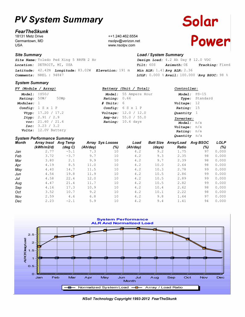
Site Summary
FearTheSkunk18131 Metz Drive
Germantown, MD
USA
++1.240.462.6554
www.nsolpv.com
NSol! Technology Copyright 1993-2012 FearTheSkunk
Site Name:
Latitude:
Tilt:
Comments:
Location:
Longitude:
Azimuth:
Elevation:
Tracking:
Toledo Ped Xing 5 RRFB 2 Hr
42.42N
60S
NREL : 94847
DETROIT, MI, USA
83.02W
0E
191 m
Fixed
System Performance SummaryMonth
Jan
Feb
Mar
Apr
May
Jun
Jul
Aug
Sep
Oct
Nov
Dec
2.77
3.72
3.80
4.19
4.40
4.54
4.58
4.47
4.16
3.52
2.59
2.23
-5.1
-3.7
2.1
8.5
14.7
19.8
22.4
21.4
17.3
10.7
4.6
-2.1
7.3
9.7
9.9
11.0
11.5
11.9
12.0
11.7
10.9
9.2
6.8
5.9
10
10
10
10
10
10
10
10
10
10
10
10
4.2
4.2
4.2
4.2
4.2
4.2
4.2
4.2
4.2
4.2
4.2
4.2
Array Insol
(kWh/m2/d)
Avg Temp
(%)
Array
(Ah/day)
Sys Losses
(%)
Load
(Ah/day)97
98
98
98
99
99
99
99
98
98
97
94
Avg BSOC
(%)(deg C)9.2
9.3
9.7
10.0
10.3
10.5
10.5
10.5
10.4
10.1
9.8
9.4
Batt Size
(days)1.75
2.35
2.39
2.64
2.78
2.86
2.89
2.82
2.62
2.22
1.64
1.41
Array/Load
Ratio
Load / System Summary
System Summary
Design Load:
Model: IS50J
Voc: 21.60 / 21.6
Isc: 3.23 / 3.2
PV (Module / Array)
Rating: 50W/
Vtyp: 17.20 / 17.2
Ityp: 2.91 / 2.9
Modules: 1
50Wp
Volts: 12.0V Battery
Config: 1 S x 1 P
Model: 55 Ampere Hour
Amp-hr: 55.0 / 55.0 Inverter:
# Units: 6
Rating: 0.66
Voltage: 12.0 / 12.0
Battery (Unit / Total)
Config: 6 S x 1 P
Rating: 10.6 days
0.000
0.000
0.000
0.000
0.000
0.000
0.000
0.000
0.000
0.000
0.000
0.000
LOLP
(%)
PV System Summary
System Performance
ALR And Normalized Load
Normalized System Load Array / Load Ratio
Month
Jan Feb Mar Apr May Jun Jul Aug Sep Oct Nov Dec
ALR O
f DesignLoad
2.5
2
1.5
1
0.5
0
Min ALR: 1.41 Avg ALR: 2.36
LOLP: 0.000 % Avail: 100.000 %Avg BSOC: 98 %
Model: n/a
Voltage: n/a
Rating: n/a
Controller:
Model: PS-15
Type: Standard
Voltage: 12
4.2 Ah Day @ 12.0 VDC
Rating: 15
Quantity 1
Quantity n/a
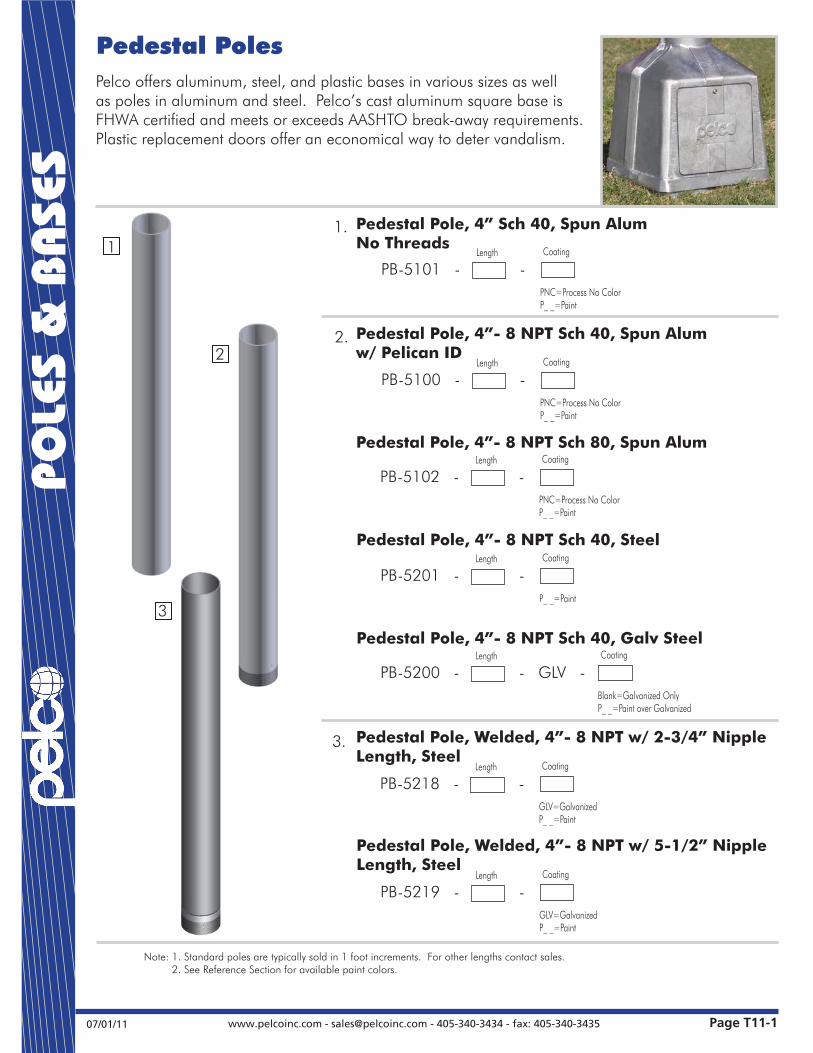
Pelco offers aluminum, steel, and plastic bases in various sizes as well as poles in aluminum and steel. Pelco’s cast aluminum square base is FHWA certified and meets or exceeds AASHTO break-away requirements. Plastic replacement doors offer an economical way to deter vandalism.
1
2
3
1.
2.
3.
Page T11-1www.pelcoinc.com - [email protected] - 405-340-3434 - fax: 405-340-343507/01/11
POLE
S &
BAS
ES
Pedestal Poles
Note: 1. Standard poles are typically sold in 1 foot increments. For other lengths contact sales. 2. See Reference Section for available paint colors.
Pedestal Pole, 4”- 8 NPT Sch 40, Galv Steel
PB-5200 - - GLV - Length Coating
Blank=Galvanized OnlyP_ _=Paint over Galvanized
Pedestal Pole, Welded, 4”- 8 NPT w/ 2-3/4” Nipple Length, Steel
PB-5218 - - Length Coating
GLV=GalvanizedP_ _=Paint
Pedestal Pole, 4” Sch 40, Spun AlumNo Threads
PB-5101 - - Length Coating
PNC=Process No ColorP_ _=Paint
Pedestal Pole, 4”- 8 NPT Sch 40, Spun Alumw/ Pelican ID
PB-5100 - - Length Coating
PNC=Process No ColorP_ _=Paint
Pedestal Pole, 4”- 8 NPT Sch 80, Spun Alum
PB-5102 - - Length Coating
PNC=Process No ColorP_ _=Paint
Pedestal Pole, 4”- 8 NPT Sch 40, Steel
PB-5201 - - Length Coating
P_ _=Paint
Pedestal Pole, Welded, 4”- 8 NPT w/ 5-1/2” Nipple Length, Steel
PB-5219 - - Length Coating
GLV=GalvanizedP_ _=Paint

Pelco offers aluminum, steel, and plastic bases in various sizes as well as poles in aluminum and steel. Pelco’s cast aluminum square base is FHWA certified and meets or exceeds AASHTO break-away requirements. Plastic replacement doors offer an economical way to deter vandalism.
Page T11-2 www.pelcoinc.com - [email protected] - 405-340-3434 - fax: 405-340-3435 07/01/11
POLE
S &
BAS
ES
Square Pedestal BasesAluminum
Note: 1. AASHTO Certified Square Aluminum Base: All Aluminum square bases above are available with AASHTO Certifications and FHWA approval. Please specify by adding the Certification Part No. C-1001 in addition to the base part number. 2. All assemblies are supplied standard with stainless fasteners. 3. See Reference Section for available paint colors.
Square Base Assembly, Alum w/ Alum Door
PB-5334 - - - -
Set Screwsin Collar
1S=1 Hex Bolt3S=3 Set ScrewsBlank=None
GroundingLug
GL=Grounding LugBlank=None
Coating
PNC=Process No ColorP_ _=Paint
Door
NL=No LogoBlank=Pelco Logo
Square Base Assembly, Alum w/ Plastic Door
PB-5335 - - - - PNC
Set Screwsin Collar
1S=1 Hex Bolt3S=3 Set ScrewsBlank=None
GroundingLug
GL=Grounding LugBlank=None
Door
NL=No LogoBlank=Pelco Logo
Square Base Assembly, AlumHeat Treated w/ Alum Door
PB-5336 - - - -
Set Screwsin Collar
1S=1 Hex Bolt3S=3 Set ScrewsBlank=None
GroundingLug
GL=Grounding LugBlank=None
Coating
PNC=Process No ColorP_ _=Paint
Door
NL=No LogoBlank=Pelco Logo
Square Base Assembly, AlumHeat Treated w/ Plastic Door
PB-5337 - - - - PNC
Set Screwsin Collar
1S=1 Hex Bolt3S=3 Set ScrewsBlank=None
GroundingLug
GL=Grounding LugBlank=None
Door
NL=No LogoBlank=Pelco Logo
15”
13-3/4”
12.0” min.14.5” max.
Grounding Lug


www.jsftech.com
Data Sheet Rectangular-Rapid Flashing Beacon: 9000 Series
AB-9405, AB-9407
Conforms to FHWA Interim Approval Memorandum (1A-11)
ApplicationsThis pedestrian-activated or remote-activated crosswalk beacon is the perfect solution for temporary or permanent locations:
Crosswalks Great for any mid-block or uncontrolled crosswalk.
Fire Stations Give your emergency vehicles a chance to enter the roadway by alerting drivers.
Parking Lots From shopping malls to private industrial sites, they’re all a hazard for pedestrians.
Construction Sites Aid pedestrians in crossing away from construction sites and closed sidewalks.
College Campuses Busy and packed with pedestrians.
Benefits High Quality Proudly designed and manufactured in North America.
Clean Technology Solar-powered and wireless to save on power bills and end roadway trenching.
Reliable Energy management system to ensure operation under all environmental conditions.
Simple Installs in minutes to minimize traffic disruption and allow for relocation and re-purposing.
Flexible Adjustable flash pattern and activation duration to control varying traffic conditions.
Elegant Self-contained, cabinet-free, discrete design to enhance streetscapes and inhibit vandalism.
COLLEGE
P
* stand not included

ContactJSF Technologies is backed by a select group of resellers around the globe. To find a representative in your region please contact us:
+1.250.544.1640
+1.800.990.2454
www.jsftech.com
SpecificationsSystem OverviewOperation Pedestrian push button or remote controlled
Flash patterns MUTCD RRFB Pulsing Pattern
Activation duration Variable from 5 seconds to 60 minutes
Min. solar requirements 48 min insolation / day
Operating temperature -40°F to +165°F (-40°C to +74°C)
Controller input voltage 4 V DC
Controller output voltage 12 V DC
Solar panels 4.5 W, 6 V, 756 mA (per panel)
Batteries BC cell, 2 V, 25 Ah Sealed lead acid,non-spillable gell, 5 year lifespan (field replaceable)
Alternate power AC / Solar hybrid available
Power ManagementRated usage 300 cycles per day, 20 second activation
Charged capacity 25 days at rated usage (without charging)
Auto brightness Auto brightness for nighttime conditions (no daytime dimming)
Self monitoring Visual notification of sub-optimal operation
CommunicationType ISM spread spectrum radio, 902-928 MHz
Range 110 yards (100 m)
Network addresses 8 unique addresses to avoid interference between multiple crosswalk locations
Compatibility All AB family units
LED ModuleStandard SAE J595 (Class 1) certified
Size Approx — 2” x 5” or 3” x 7”
Horizontal LED pivot 60°
LED color Amber
Physical DesignDesign Two piece system: beacon and solar engine
Color Black, green or yellow
Signal head 6061-T6 powder coated aluminum
Solar engine 6061-T6 powder coated aluminum
Available mounting for Poles: 2” – 8” Telespar and U-Channel Side mounting
WarrantyStandard 5-year Manufacturer’s Limited Warranty
on all parts
4"
( 4" MOUNT SHOWN)
18-5/8"
43°
12-3/4"
12-1/2"
22"
Dimensions are in Inches 1/16"
18-7/8"
43°
12-7/8"
12-5/8"
33"
Dimensions are in Inches 1/16"
Solar Engine — Super Duty
Details Standard Super DutySolar Panels 4 panels 6 panels
Batteries 6 batteries 8 batteries
Manufactured Weight 49 lbs. (22 kg) 60 lbs. (27 kg)
Shipping Weight 55 lbs. (25 kg) 68 lbs. (31 kg)
Rev B.1 — May 9, 2013
Rectangular Rapid Flashing Beacon, 4 LED - Double sided. Signal Head (2”x 5” LEDs shown) Solar Engine — Standard
*Specifications subject to change without notice.