repair & maintain lionel …
TRANSCRIPT

2013618258
LIONEL POSTWAR LOCOMOTIVES
REPAIR & MAINTAINwww.ClassicToyTrains.com
A supplement to Classic Toy Trains magazine
YOU CAN FIX IT!REPLACE PICKUP ROLLERS & SHOES
REPAIR UNIVERSAL LIONEL MOTORS
REWIRE STEAM & DIESEL MOTORS

www.ClassicToyTrains.com 3
Pickup rollers and shoes – those out of sight, out of mind, center-rail electrical contacts that are important in a locomotive’s perfor-
mance – should never be ignored.Certainly, at a minimum, these pick-
ups should be kept clean so they roll or slide freely, but that alone isn’t enough. Even under normal use, they sustain a considerable amount of wear and tear over time. When the pickups have grooves worn into them or are badly pitted from hours of arc-ing, it’s time to replace them.
In fact, the Lionel Service Man-ual recommended changing loco-motive rollers or sliding shoes every time the unit was over-hauled. This mandate, though probably motivated in part by Lio-nel’s desire to sell replacement parts, made as much technical sense in the past as it does today. With all of the electronic circuitry that has come along in recent years, good electrical contact with the rails is essential.
Though the essential function
of pickup rollers and shoes remains the same, the contact design itself has changed. Maintenance procedures vary, depending on the locomotive’s vintage and some hardware variations. Basically, we can break the procedures into four categories. Here’s how to handle each type of repair.
Some cautionary notesAs described, you’ll find roller or
shoe replacements a doable job. But there is a caveat or two to consider.
First, bear in mind that Lionel made many different roller sizes and shapes over the years – some were bev-eled, some were not, as the photos on this page suggest. Be sure your replace-ment is the correct one, because exact dimensions are important. Inserting the wrong roller, even if it seems to fit, can result in operational problems, particularly when it goes over switches. If you don’t know the part number, take the old roller with you to your Lionel parts dealer.
Second, note the exclusion of Lionel's Bakelite-cased “Scout” motors in this article. They were excluded for good reason: Their pickups were not designed to be easily replaceable. Fortunately, in many cases, the pickups out-lasted the motors themselves anyway.
Once you’ve replaced worn-out pickups, you can let these important electrical contacts hide themselves away again beneath the locomotive and run their course. But never take them for granted.
&PICKUP ROLLERSSHOES
REPAIR
How to replace tHem on prewar, postwar & early modern engines
by Ray L. Plummer photos by Jim Forbes
© 2013, Kalmbach Publishing Co. All rights reserved. This publication may not be reproduced in part or in whole without written permis-
sion from the publisher. Published by Kalmbach Publishing Co., 21027 Crossroads Circle, Waukesha, WI 53187-1612. Printed in U.S.A.
Rollers were made in many shapes and configurations. When replacing rollers, use the old one as a guide.

4 Repair Lionel Postwar Locomotives
Pre-1950 shoes and rollersMost of LioneL’s pre-1950 O-27 loco-motives and some of its prewar O gauge streamliners were fitted with sliding shoes instead of rollers. Not surprisingly, these shoes wore out faster than rollers.
When rollers were used, they were one-piece units with protruding “shafts” mounted on sprung collector arms, which had holes in them to accommodate the protrusions. If not kept lubricated, these holes became elongated, allowing exces-sive play and decreasing the roller’s effi-ciency. The rollers themselves were made of soft metals (brass, copper, or a special alloy) that were prone to rapid wear.
You can easily replace these contacts, whether rollers or shoes, with a screw-driver and needle-nose pliers. No actual disassembly is required.
To replace a roller, wedge a screw-driver blade between one end of the roller and the side of the collector arm assembly (fig. 1). Twist the tool until the roller tip clears its mounting hole and drops out. As an alternative, needlenose pliers may be used to bend one side of the collector arm until the roller is loose enough to be removed.
Insert the new roller, and bend the col-lector arm back into position (fig. 2). The roller should be free to spin easily in its mounting.
To replace a contact shoe, slide a slot-head screwdriver blade or any other thin metal instrument under the fiber bottom
plate, between the shank of the shoe and the leaf spring clip that holds it in place (fig. 3). You should be able to feel the hook at the end of the shank, if your tool is inserted correctly – about 3⁄4 inches in from the exposed end of the shoe.
Twist the screwdriver just enough to release the hook from its mooring slot in
the spring. (Be careful not to over-bend the spring.) You will then be able to slip the shoe out of its mounting.
Ease the new shoe into the same posi-tion. You should hear a click as it snaps into place. In some cases, it may be necessary to lift the leaf spring slightly to get the hook on the shoe shank into the slot (fig. 4).
Post-1950 reusable roller Pinfor post-1950 locomotives, a new two-piece contact was designed. It used a tougher, sintered-iron roller with a hole running through it lengthwise and a sta-tionary pin riveted to one side of the col-lector arm.
You can either replace both the worn-out roller and its mounting pin (as described on page 5) or try to reuse the original pin, a shortcut that repair techni-cians have used for some time with usu-ally good results.
The roller pin must be in good condi-tion – not severely worn – and solidly anchored.
First, with needlenose pliers, bend the side of the bracket with the larger hole away from the pin, then bend the other side of the bracket until the roller clears
the bracket assembly (fig. 5).Clean the pin with a solvent to remove
any built-up dirt and grease. Slip the new roller into place. Check to see that there is not excessive play between it and the roller pin.
If the fit is acceptable, carefully – and one at a time – bend the brackets back to their original configuration (fig. 6).
Check to see that the new roller is able to spin freely. Adjust the mounting bracket, if necessary.
Fig. 5. With pliers, outwardly bend the side of the bracket that has the larger hole. Then do the same to the other side of the bracket.
Fig. 6. Once you’ve installed the old pin and new roller, squeeze the bracket shut again, making sure the roller is able to turn freely.
Fig. 1. After wedging a slot-head screw-driver into position, twist until the old roller tip clears its mounting hole.
Fig. 2. Use a pair of pliers to bend the collector arms back together to hold the new one-piece roller in place.
Fig. 3. To replace shoes, slide a screw-driver under the fiber bottom plate and between the shank of the shoe and the leaf spring clip until you feel the hook at the end of the shank.
Fig. 4. Slide a new pickup shoe into position and listen for the click to con-firm the pickup shoe has snapped into place properly.

www.ClassicToyTrains.com 5
Post-1950 Pin and roller rePlacementIF YOUR OLD roller pin isn’t reusable, or if you prefer two new parts instead of one, here’s how to swap out both parts.
Although the sintered-iron rollers are indeed tougher than the old soft-metal ones, they are also not as easy to replace. To do the job right without the shortcut described on page 4, the whole collector-arm assembly has to be removed from the locomotive first.
To begin, detach the collector arms from the locomotive by taking out the screws or pivot pins that hold the collec-tor arms in place.
Using a file or grinding tool, remove the end of the roller pin that is riveted to the collector arm (fig. 7). Note: If you’re using a motorized grinding tool, use eye protection and secure the roller assembly in a vise; never use your hands to hold the roller assembly still.
When enough metal is taken off the pin, it should be loose enough to allow its easy removal from the collector arm (fig. 8). The roller will come along with it.
Position a new roller between the holes in the collector arm. Slip the new pin’s smaller end into the arm’s larger hole, then push it through the roller, and then seat it all the way inside the smaller arm hole (fig. 9).
Carefully position this entire assembly, with the large hole down, on an anvil or some other hard, unyielding surface. With a light hammer (preferably a ball-peen hammer), lightly strike the small end of the roller pin until it is firmly riv-eted into place (fig. 10).
Check to make sure that the roller is able to spin freely. If necessary, adjust the assembly accordingly. Then reattach the collector arm to the locomotive, and the job is done.
late Postwar and into the early modern eraLIOneL’s Use of sintered iron grew rapidly in the post-war era. The theory was that the harder iron rollers would not wear out as fast as the older ones, and they could be permeated with a permanent lubricant, consequently elimi-nating the need for periodic oiling.
Naturally, tough as they were, they did eventually wear out. Because these roll-ers were difficult to replace, Lionel later sought other design options.
During the late postwar era and into the modern era (1970 to today), Lionel began using small “snap-in” roller-bracket
assemblies that fit into a slot in a leaf contact spring – very much as the old sliding con-tact shoes did – on a number of low-end steam and diesel locomotives.
Basically, Lionel made the entire roller assembly dispos-able, allowing service techni-cians or the locomotive’s
owner to easily and quickly swap out the parts.
For these locomotives, you can certainly use the same roller replacement techniques outlined above if you wish. However, at just a few dollars each for a complete replace-ment assembly, it hardly seems worth the effort.
Fig. 7. After detaching the collector-arm assembly from the locomotive, file or grind off the end of the roller pin.
Fig. 8. When you’ve removed enough metal, use needlenose pliers to remove the roller pin to release the old roller from the arm.
Fig. 9. With the new roller in position, push the new pin through the side of the arm that has the larger hole and then into the smaller hole.
Fig. 10. Using a ball-peen hammer and an anvil, carefully tap the small-hole end of the roller pin until the pin is riveted in place.

6 Repair Lionel Postwar Locomotives
Look inside a bunch of well-used Lionel locomotives and you may find yourself assum-ing no two were ever wired the same. Questions about
internal wiring for Lionel locomotives are certainly understandable.
Tinkering by inquisitive kids, well-meaning adults, and even supply-strapped service technicians often camouflaged the original wiring scheme of a given locomotive. As a result, the internal wiring of many locomotives today can be a jumble of
MOTOR WIRINGREPAIR LioneL wired Locomotives three different ways
by Ray L. Plummer photos by William Zuback • illustrations by Jay Smith
In this article, repair expert Ray L. Plummer demystifies Lionel's postwar steam and diesel motor wiring and shows how you can put these classic engines back to work.

www.ClassicToyTrains.com 7
loose connections, tangled wires, and imperfect repairs.
Maybe that’s to be expected in a locomotive that’s survived for half a century or longer in the hands of numerous owners with varying techni-cal repair skills. At some point, however, you really need to know how a locomo-tive was originally wired.
Here are three basic wiring patterns – which, for convenience, I’m calling Type A, Type B, and Type C – that Lio-nel used most often to connect motor components with their mechanical
reversing units and center-rail pickups. Almost all of the steam and diesel engines manufactured from about 1930 to the onset of the electronic circuit board age were wired according to one of these patterns.
I’m intentionally omitting two other wiring patterns: the sealed can-style motors of the modern era (which uti-lize electronic technology too complex to sum up in a few short paragraphs), and the infamous Bakelite-encased “Scout” motors used in some postwar starter-set steam locomotives. (They
are almost impossible to repair and don’t have external wiring anyway.)
Also, I should note that while Lionel did use wire color-coding at times, the code is neither certain nor consistent over time. Plus, service technicians, even those employed by Lionel Service Stations, tended to use whatever hookup wire they happened to have on hand. Therefore, the colors specified in the following descriptions are by no means absolute.

Headlight lamp
Motor
E-unit
Roller pickup
Ground
Headlight lamp
Ground
Motorarmature
Yellow wiresto brushes
Ground
Motor �eld
E-unitdrum E-unit plunger
E-unit coilSolder lug
E-unitswitch
Contact rollers
Type A wiring
Headlight lamp
Motor
E-unit
Roller pickup
Type B wiring
Ground
Headlight lamp
Ground
Motorarmature
Ground
Motor �eld
E-unitdrum
E-unit coilSolder lug
E-unitswitch
Contact rollers
E-unit plunger
8 Repair Lionel Postwar Locomotives
Type A wiring, by far the most com-mon, is found on many steam, diesel, and electric-profile locomotives. Included are the open-frame, spur-geared integrated motor/mechanisms, as well as the separate, heavy-duty motors on worm-geared steamers and the better diesels and electrics.
Designed for use with conventional three-position reversing units, Type A wiring has two distinguishing charac-teristics: Both brushes have their own individual wires leading to them, and one end of the motor field coil is
grounded to the frame, so there is only one wire leading to the field coil.
The center-rail pickup wire (usually black or red) goes to the solder lug on the side of the reversing unit, opposite the lock-out lever contact eyelet.
The solder lug on the side of the reversing unit is also connected to:
• one end of the reversing unit coil,• the single-finger contact farthest
from the solder lug, on the four-con-tact strip inside the reversing unit (usually a black wire),
• the headlight (in most cases),• the lead to the smoke generator, if
the locomotive has one,• and the wire to the horn relay
coil, if the locomotive has one.The two-finger contact in the mid-
dle of the four-contact strip inside the
reversing unit is wired (often this wire is yellow; sometimes it’s a blue wire) to one of the brushes.
The single-finger contact closest to the solder lug on the four-contact strip inside the reversing unit is wired to the motor field coil. The other end of the coil is grounded, so there is only one wire to the coil.
The two-finger contact at the bot-tom of the reversing unit is connected to the second motor brush (usually with a yellow wire).
Type B wiring is most often found on prewar and early postwar O-27 locomo-tives. Motor mechanisms are of the integrated, spur-gear variety in sheet-metal or die-cast frames.
Designed for use with three-position reversing units, Type B wiring has two distinguishing characteristics: One of the two motor brushes is grounded to the frame, and there are wires leading to both ends of the motor field coil.
The wire from the center-rail pickup (usually black) is connected to the sol-
der lug on the side of the reversing unit that is opposite to the lock-out lever contact eyelet.
The solder lug on the side of the reverse unit is also connected to:
• one end of the reversing unit coil,• the single-finger contact farthest
from the solder lug, on the four-con-tact strip inside the reversing unit (usually a black wire),
• and the headlight.The two-finger contact in the mid-
dle of the four-contact strip inside the reversing unit is wired to one end of the motor field coil (could be a yellow, blue, or green wire).
The two-finger contact at the bottom of the reversing unit (often yellow) is wired to the other end of the field coil.
The single-finger contact closest to the solder lug, in the four-contact strip inside the reverse unit (sometimes yel-low or green wire), is connected to one brush. The other brush is grounded to the frame with a sheet-metal tab.
Type A locomotives
Type B locomotives
Type C wiring
Headlight lamp
Ground
Ground
Ground
Motorarmature Solder lug
Double �eldTwo-position
reversing unit
Contact rollers
Headlight lamp
Motor
E-unit
Roller pickup
PLEASE PROOF:Individual illustrators, designers, art directors, and editors must proof and sign this form.
TitleIssueJob #CodeProofDateReturn
IllustratorDesignerArt Dir.Story Ed.Copy Ed.Man. Ed.Editor
CTTSept 04mag-ctt-sep04CJ0904106-03-04
Jay
www.ClassicToyTrains.com 9
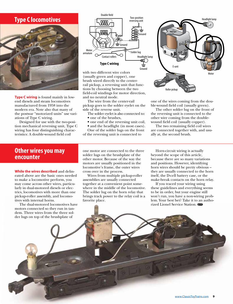
Type C wiring is found mainly in low-end diesels and steam locomotives manufactured from 1958 into the modern era. Note also that many of the postwar “motorized units” use vari-ations of Type C wiring.
Designed for use with the two-posi-tion mechanical reversing unit, Type C wiring has four distinguishing charac-teristics: A double-wound field coil
with two different wire colors (usually green and copper), one brush wired directly to the center-rail pickup, a reversing unit that func-tions by choosing between the two field-coil windings for motor direction, and no neutral mode.
The wire from the center-rail pickup goes to the solder eyelet on the side of the reverse unit.
The solder eyelet is also connected to:• one of the brushes, • one end of the reversing unit coil,• and the headlight (in most cases).One of the solder lugs on the front
of the reversing unit is connected to
one of the wires coming from the dou-ble-wound field coil (usually green).
The other solder lug on the front of the reversing unit is connected to the other wire coming from the double-wound field coil (usually copper).
The two remaining field coil wires are connected together with, and usu-ally at, the second brush.
Other wires you may encounter
While the wires described and delin-eated above are the basic ones needed to make a locomotive perform, you may come across other wires, particu-larly in dual-motored diesels or elec-trics, locomotives with more than one pickup-roller assembly, and locomo-tives with internal horns.
The dual-motored locomotives have motors connected so they run in tan-dem. Three wires from the three sol-der lugs on top of the brushplate of
one motor are connected to the three solder lugs on the brushplate of the other motor. Because of the way the motors are usually positioned in the locomotive’s frame, the outer wires cross over in the process.
Wires from multiple pickup-roller assemblies are usually connected together at a convenient point some-where in the middle of the locomotive. The solder lug on the horn relay that brings track power to the relay coil is a favorite place.
Horn-circuit wiring is actually beyond the scope of this article, because there are so many variations and positions. However, identifying horn wires should be pretty obvious – they are usually connected to the horn itself, the D-cell battery case, or the make-break contacts on the horn relay.
If you traced your wiring using these guidelines and everything seems to be in order, but your engine still won’t run, you have a non-wiring prob-lem. Your best bet? Take it to an autho-rized Lionel Service Station.
Type C locomotives

10 Repair Lionel Postwar Locomotives
No matter how old Lionel O gauge locomotives may be, or how tired they seem, most
of them can be mechanically rejuvenated to perform satis-factorily. These classic toy train warhorses, ruggedly built, were designed for long life if routinely serviced and maintained. In fact, most of them have withstood the rav-ages of time better than their original owners!
In many years of repairing locomotives, I have brought hundreds of ailing Lionel
basket cases back to life. In all that time, only about a half-dozen (exceptionally pounded, burned, or dissected beyond hope) couldn’t be resuscitated.
Repairing most trains is easier than you might think. I once found a 60-year-old train in the loft of a farmer’s barn, where it had spent more cold northern winters and hot summers than any-one could remember. A fam-ily of mice had even made a nest in the box and left behind over a pound of pet-rified “evidence.”
I thought the engine was a goner for sure – until I brushed out all of the debris, cleaned and lubed the motor, and put the juice to it. The thing sputtered twice and took off like a demon was chasing it!
Unless you can top that story, you have no excuse for not at least trying, with some step-by-step guidance.
Meet the motorAll Lionel motors from
the company’s first O gauge trains in 1915 through the postwar era (and beyond)
by Ray L. Plummer photos by William Zuback
Clean and rebuild the heart of your o gauge loComotives
UNIVERSAL LIONEL MOTORSREPAIR Repairing most trains is easier than you may think. Often a simple cleaning and lubrication job is all that's needed to get a balky engine running like a champ. Here’s how to do it right.

www.ClassicToyTrains.com 11
are basic variations on the same concept.
Most of the principles used to clean and repair Lio-nel electric motors can be applied to trains made by other toy train manufactur-ers as well. Regardless of their shape or configuration, whether installed in steam, diesel, or electric profile engines, these motors are all three-pole, series-wound uni-versal motors capable of run-ning on either AC or DC low-voltage current.
In the past decade or so, sealed “can-style” motors and electronic circuit boards have all but replaced the old mechanical technol-ogy. These new devices are designed to be replaced, not repaired, when worn out, so the servicing tips outlined in this article won’t apply.
AC-DC universal motor components
Whether integrated within a steam locomotive framework and drivers, or appearing as a separate assembly screwed to a steamer frame or diesel power truck, all Lionel uni-versal motors have the same basic elements:
• A stationary field. This is a stack of steel plates, shaped like a horseshoe and riveted together. The field coil consists of many turns
of enamel-coated copper wire, wrapped around the center of the horseshoe.
• A three-pole armature. This is another stack of steel plates, shaped like a clover leaf and mounted on a shaft. This assembly spins around within the stationary field. Three coils of enamel-coated wire are wrapped around the three sections of this stack. Each pole piece terminates with a wedge-shaped copper segment on the face of the armature. Together, the three pole pieces form a broken circle known as the commutator.
• Two brushes. Usually made of copper-graphite, these little cylinders contact the commutator’s surface. Two brush springs hold them firmly in place within individual brush wells, located on an insulated brushplate.
How it worksWhen electricity flows into
the field coil, the field turns into an electromagnet, the ends of which attract and repel simultaneously. Because of its horseshoe shape, the attract/repel forces are focused close together at the end of the field. The brushes are wired in series with the field, so electrical current flows into them and into the armature at the same time.
Oil Oil Oil
Oil Oil OilGreaseGrease
Armature shaftBrush
Brush spring
Brush well
Stationary field
Commutator surfacePole piece (part of the armature assembly)
These attract/repel forces cause the armature coil positioned between the ends of the field to move out of the way. When it does, another coil automati-cally moves into position. It must also move out of the way, and as it does, a third comes into place. This action repeats itself, and soon the armature is spin-ning rapidly, often develop-ing as many as 4,000 rpm.
Routine maintenanceBecause it revolves so
fast, the armature requires frequent attention in the form of regular routine maintenance after two or three hours of running time, or whenever it seems to be needed.
• Lubrication. Oil both ends of the armature shaft if they are accessible. One drop of oil dispensed on the end of a toothpick is
Oil the ends of the armature shaft, using a drop of oil dispensed from the end of a toothpick or (even better) a hobby oiler. On steamers with the motor mounted sideways between the drive wheels, the shaft can often be oiled from both sides. On diesels, the top side of the shaft is easily accessible.
While focusing on the motor, don’t forget that a properly lubri-cated drive train not only protects the gears but decreases stress on the motor. Both gears and axles should be lubricated as indicated.

12 Repair Lionel Postwar Locomotives
enough. If you apply too much, it will get into the brushes and commutator.
On some motors, only one end of the armature shaft is exposed, while the other end rides in a lubri-cant-filled reservoir. A third type of motor has a felt oil-ing wick next to the arma-ture bearing. Give it a drop or two. While you’re at it, oil the axles too, one drop on each axle bearing.
(Use common household oil, such as 3-in-1, or any of the special lubricating oils made for model trains. What you use isn’t as impor-tant as whether you use it regularly.)
Lightly coat the drive train gears with grease. (Use any of the special hobby lubricants or white lithium grease.)
• Cleaning. In most cases, you can clean your locomo-tive’s commutator without taking it apart. You can use an aerosol cleaner/lubri-cant spray, such as LPS-1 (available at hardware and automotive stores) or min-eral spirits or alcohol (dena-tured or isopropyl) on cot-ton swabs. Wipe down the commutator surface repeat-edly until it shines and fresh swabs no longer turn black.
This simple routine per-formed regularly will keep your motor from arcing severely and running hot, thereby reducing the dan-ger of the armature wind-
ings shorting or burning out. And your train will run better too!
Heavy-duty helpThere may come a time
when your locomotive still runs erratically, or not at all, after routine maintenance. In that case, a bit of trouble-shooting, deeper cleaning, or even overhaul may be needed.
• Motor removal. Remove the motor mechanism from the locomotive body. How this is done depends upon the type of locomotive. With steamers, it’s a good idea to remove the front and rear trucks and disconnect the valve gear, crosshead, and rod assemblies before separating the mechanism from the body. Many are attached with screws through the boiler top or bottom plate. Some also have transverse screws or pins running through the motor sideplates.
Diesel or electric bodies come off more easily. They are usually attached with one or two obvious screws front and rear. Remove the power truck from the frame. This may require unsolder-ing a few wires. Work slowly and carefully. Don’t force anything. Make notes dur-ing disassembly so you can retrace your steps when put-ting things back together.
• Motor cleaning. Thor-oughly clean the mechanism
inside and out. Remove the accumulation of dust, dirt, and caked-on grease by washing everything in a bath of mineral spirits or some other degreasing solvent.
You can dip the mecha-nism or apply the solvent with an old paintbrush. Get into every crack and corner, working the dirt loose with the brush. Continue until the entire mechanism is clean. Allow it to air dry completely.
Use caution when work-ing with solvents. They are very combustible and must be used only in a well-venti-lated area and away from sparks or flames. Many peo-ple limit solvent use to out-doors only.
When you have made sure everything has dried,
test-run the mechanism. Sometimes a thorough cleaning will eliminate many of the gremlins. You may want to carefully and spar-ingly lubricate all bearings first, because the solvent bath removes all traces of lubricant. If you don’t do this, you will learn firsthand what “squeaky clean” really means!
• Brushplate removal. Remove the brushplate and motor brushes. You’ll find either two or three screws that secure the plate on top of the motor. Be careful not to lose the brushes and the brush springs – sometimes they pop out! Set them aside temporarily.
• Armature testing. Test the armature for shorts and open windings. This is par-
After removing the brushes, remove dirt from the brush wells with a cotton swab and a cleaning solvent.
On diesels, the brush plate assembly must be removed to gain access to the commutator for cleaning. On some steamers, the commutator face is visible.
Clean the commutator surface with an aerosol cleaner/lubricant spray, such as LPS-1.

www.ClassicToyTrains.com 13
ticularly important if your locomotive has been run-ning erratically, noisily, or too slowly. There should be electrical continuity between the segments of the commutator face and no electrical continuity between the commutator segments and the armature shaft.
This testing is easy if you have a volt-ohm meter (VOM) or another simple continuity tester. If you don’t have one, you can use the leads from your trans-former by turning the throt-tle to middle range and then touching one lead to the armature shaft and the other to one of the commu-tator segments. There should be no spark gener-ated. Repeat this test with
the other two commutator segments.
If sparking occurs, the armature is shorted against the shaft and must be rewound or replaced. (Motor rewinding is a highly technical specialty and is beyond the scope of this article. It may be cheaper and easier to replace the armature with a new or high-quality used armature.)
Next, touch one of the transformer leads to one of the commutator segments. Then touch the other lead wire to the other two com-mutator segments in turn. There should be a small spark produced each time. Go around the commutator and test each segment against the other two. There should always be a spark. No
spark indicates a break in the continuity – an open cir-cuit. Again, you may have to rewind or replace the arma-ture. However, one of the coil wires simply may have broken loose from its anchor on the commutator face. If you are lucky, the broken wire will still be long enough to be resoldered back into place.
• Commutator face. Clean and dress the commu-tator face. The LPS-1 cleaner/lubricant or a sol-vent cleaner (mineral spirits or alcohol) and cotton swabs are probably all you need. Spray the cleaner/lubricant directly into the commutator face and swab until the surface is shiny and clean. Use a round toothpick to remove any
gunk lodged between the commutator segments.
In extreme cases where the commutator face is severely worn or pitted, or has circular grooves cut into its surface, lightly dress it with fine emery paper until the grooves and pits are gone. You should see no more black rings or marks, just a clean copper surface.
• Brushes and springs. Clean, repair, or replace the brushes and springs. There are at least two sides to the ongoing controversy about replacing brushes. Some service technicians routinely replace brushes and springs every time a motor is taken apart. Others believe in con-servation, stretching and bending the brush springs until only a nub of copper-
Use a toothpick to clean the gunk out of the gaps between the poles of the commutator.
Remove the loosened dirt on and around the commutator sur-face with a cotton swab.
With an emery cloth, smooth and dress the commutator until all pits and grooves are gone.
When you’re done, you should have a shiny copper surface.

14 Repair Lionel Postwar Locomotives
graphite cylinder remains. I personally think that
brushes should be replaced when they are so short that the brush wells can no lon-ger hold them firmly in place and they wobble from side to side. Brushes should fit snugly within the brush wells, but there should be no binding to inhibit the brushes’ free “in-and-out” movement as they ride on the commutator face.
That’s why it is important that the wells be thoroughly cleaned too. Spray the insides with LPS-1, and fol-low up with a cotton swab or pipe cleaner in the smaller diameter wells until all traces of dirt are removed. Unless the brushplate is warped or cracked, you shouldn’t have to spend any more time on this assembly.
Clean the brushes them-selves with LPS-1 or mineral spirits. Wipe away all black residue from the sides and ends. They were originally a dark copper color and should appear that way again.
If the brushes have worn into a lopsided angle, they should be squared off by gently rubbing them with emery paper or a fine file until their ends are perpen-dicular to their sides. This will assure good contact with the commutator face.
• Brush spring tension. In most cases, little or noth-ing will need to be done to brush springs. If there is evi-dence of uneven tension, such as a difference in brush length or the locomotive running faster in one direc-tion than the other, adjust
or replace your springs. Ten-sion should be equal on both brushes.
The problem in diagnos-ing improper spring tension is that either too much or too little can result in the same symptom – a motor that loses power or runs slower than it should.
You’ll rarely find too much tension, except in cases where the motor was previously “repaired” by someone who didn’t get it quite right. Too little ten-sion is often the result of brushes shortened by exces-sive wear or springs that have lost their resiliency due to overheating.
The adjustment opera-tion can be tricky and requires patience because it is done by trial and error. Start by putting the mecha-nism on blocks or clamping it in a vise so that all wheels and gears move freely. Hook transformer leads to one of the third-rail pickups and a spot on the frame that is grounded. Turn the throttle up about halfway.
With the motor running, carefully poke a toothpick into each brush well, to apply more pressure against the spinning commutator. If the motor speeds up, the spring tension is too weak. Adjust the coil springs by stretching them slightly. You can bend flat or wire springs to apply more pressure. Do these bending and stretch-
ing operations a little at a time. Keep retesting until the motor no longer speeds up when the brushes are prodded.
Too much tension can be detected by simply loosen-ing the brushplate slightly. With the motor running, back off each brushplate screw a half-turn at a time.
If the motor speeds up appreciably, this can indi-cate that the spring tension is too great. It could also indicate a faulty or worn brushplate bearing. Flat or wire springs may be bent back to reduce the tension. Shorten coils by snipping off a winding or two. Adjust and test a little at a time until the motor runs at full speed with the brushplate tight.
Perhaps you can see why so many service technicians routinely replace brushes and springs – it usually elim-inates the need for these tedious adjustments. But if you’re like me and want to save a buck or two, it is worth the extra effort.
That takes care of over-hauling the motor. If you’ve been able to follow my sug-gestions, your O gauge loco-motive should be running at its best.
For more information, check out the Restoration & Repair sec-tion under the Collecting tab on ClassicToyTrains.com.
ON THE WEB
Use a volt-ohm meter to test the continuity between the seg-ments of the commutator face.
Also make sure there is no continuity between the commutator segments and the armature shaft.
Clean the brushes thoroughly with a solvent and gently file the contact points, if needed.
Traditional trackplans for toy trains
I n f o r m at I o n S tat I o n
plans for toy trainsI N F O R M AT I O N S TAT I O N
Repair & maintenance of operating cars
I n f o r m at I o n S tat I o n
Details for toytrain scenery
P17091
Just click it, buy it, and use it!To learn more or to order, visit
www.ClassicToyTrains.com/Downloads
Don’t Wait!Plus, keep them handy for future projects!
Topics include:• Electricity, command control, and wiring • Postwar Lionel collecting, repair, and maintenance • Layout planning, construction, and scenery
Instantly download articles directly to your desktop.We’ve bundled some of the best articles from Classic Toy Trains into Information Station packages you can purchase, download, and print right at home.
Getting the information you need has never been so easy!