Œ round die products die components/die... · 2009-07-10 · 4 *see page 3 for details. see pages...
TRANSCRIPT


2
BUSHINGSGeneral Information � Bushings .................... 2 & 3STANDARD SHOULDER BUSHINGSBronze Plated & Solid Steel ............................. 4Solid Bronze & Self-Lubricating ...................... 5Pressed Fit ........................................................ 6Bushings for Lifter Pin � Metric ....................... 6Long & Extra Long Shoulder Bushings .......... 7SHORT SHOULDER BUSHINGSBronze Plated ................................................... 8Solid Bronze ..................................................... 9Self-Lubricating ................................................ 10METRIC BUSHINGSNAAMS............................................................... 11 & 12Standard Shoulder Bushings � Metric ............ 13Long & Extra Long Shoulder Bushings � Metric .......................... 14Short Shoulder Bushings Metric ..................... 15
TECHNICAL INFORMATIONToe Clamp Selection ......................................... 16Toe Clamp Placement ...................................... 17Bore Sizes for Pins & Bushings ...................... 18
MISCELLANEOUS BUSHINGSRunning Fit Bushings � Hardened .................. 19Running Fit Bushings � Soft ............................. 20Guide Bar Bushings (Wiper Bushings) ........... 21Precision Bearings ........................................... 21
GUIDE PINSGeneral Information � Pins............................... 22Straight Guide Pins TN & ATN ......................... 23Straight Guide Pins TPB .................................. 24Straight Guide Pins TPC .................................. 25Straight Guide Pins NAAMS ............................. 26Straight Guide Pins Hollow .............................. 26Straight Guide Pins TN Metric ......................... 27Straight Guide Pins TPB Metric ....................... 27
All bronze plated shoulder bushings mustbe wring-fit in the die shoe. It is alsorecommended that Solid Bronze shoul-der bushings be mounted similarly.
Bronze plated bushings feature figure 8oil grooves for maximum lubrication. Forlong wear, bronze plated bushings shouldbe lubricated with a high temperature,high pressure lithium grease on aregular basis.
Self-lubricating bronze with graphitebushings require initial lubrication withlight oil. Periodic lubrication will extendthe life of self-lubricating bushings. Donot use grease.
GUIDE PINS, ContinuedGuide Pins � Tap Fit (Demountable) ................ 28 & 29Guide Pins � Shoulder Inch .................................................................. 30 Metric ............................................................... 31Guide Pins � Removable .................................. 32Stripper Guide Pins & Bushings...................... 34 & 35
STOCK LIFTERS75 Stock Lifters ................................................. 36112 Stock Lifters ............................................... 3775 Rail Lifters .................................................... 38112 Rail Lifters .................................................. 39Mini Lifters ......................................................... 40Repair Parts ...................................................... 41
SPOOL TYPE PAD RETAINERSLocking Retainers, Standard ........................... 42Locking Retainers, with flats ........................... 43Reverse Retainers, Standard ........................... 44Reverse Retainers, with flats ........................... 45Metric Retainers, NAAMS ................................. 46
Pry Bars ............................................................ 47
SHOULDER BUSHING STYLES
Standard
AC-GACACB-GACB
Short
SC-GSCSCB-GSCB
Long
LAC-GLAC
Extra-Long
XLAC-GXLAC
H&O DIE SUPPLY, INC. 1-800-222-5441 [email protected]

3
Slight taper on wring fit diameter facilitates installation. (This featureis standard on all bronze plated and solid steel shoulder bushingsunless otherwise noted.) Bushings are held in place with toe clampsand screws unless otherwise noted.
In the following pages bronze plated and solid steel bushings whichare listed as ground are �LDSS� ground.
LAMINA DIE SETSTANDARD GRIND (LDSS)
Tapers.0005
NominalWring FitDiameter
D1NOMINAL
PINDIAMETER
LAMINABUSHINGS
I.D. DimensionsClass 1 Class 2 Class 3
3/4 .7503 .7502
.7506 .7503
.7510 .7506
7/8 .8753 .8752
.8756 .8753
.8760 .8756
1 1.00031.0002
1.00061.0003
1.00101.0006
1-1/4 1.25031.2502
1.25061.2503
1.25101.2506
1-1/2 1.50031.5002
1.50061.5003
1.50101.5006
1-3/4 1.75031.7502
1.75061.7503
1.75121.7507
2 2.00032.0002
2.00072.0003
2.00122.0007
2-1/2 2.50062.5004
2.50122.5006
2.50182.5012
3 3.00083.0006
3.00143.0008
3.00233.0014
3-3/4 � 3.75183.7510
3.75283.7518
4-1/2 � 4.50254.5015
4.50354.5025
GUIDE BUSHINGSClass 1 & 2 bushing dimensions shown opposite are for use in pre-cision die sets.
Class 3 bushings are for use with automotive, hardware, forming ordraw dies where stamping stock is thicker than 1/16�, and clear-ances between punch and die sections will be more than .003� perside.
! Bronze-PlatedBushings Available inClass 1 or Class 2
! Solid BronzeBushings Available inClass 1 or Class 2
! Hardened SteelBushings available inClass 2
! Self-LubricatingBushings available inClass 3
We are not restricted to the above parameters. Every quotewill be analyzed for manufacturing possibility.
Specials have become very important at Lamina. The table belowwill give a basic idea of our everyday manufacturing capabilities. Ifyou have a need for special bushings, please send your requestsfor quotations. See page 22 for pin manufacturing capabilities.
.750 1 2.0 32 25 1501.000 1 3.0 40 25 1501.250 1 6.0 50 25 3501.500 1 6.0 63 25 3501.750 1 10.0 80 25 3502.000 1 14.0 100 25 3502.500 1 14.0 125 25 3503.000 1 14.0 � � �.625 1 2.0 � � �.750 1 3.0 19 25 100.875 1 4.0 � � �
1.000 1 5.0 � � �1.250 1 7.0 � � �1.500 1 7.0 � � �1.750 1 7.0 40 25 1502.000 1 9.0 50 25 2252.500 1 9.0 63 25 2253.000 1 9.0 80 25 2253.750 1 9.0 100 25 2254.500 1 9.0 125 25 225.5000 3.5 5.0 � � �.625 0.375 5.87 12.5 9 50.750 0.375 5.87 � � �.875 0.375 5.87 20 9 140
1.000 0.375 5.87 � � �1.250 1 6.0 � � �1.500 1 6.0 � � �1.750 1 6.0 40 9 1502.000 1 6.0 � � �2.500 1.25 8.0 � � �3.000 1.25 8.0 � � �3.750 2 16.0 � � �4.500 2 16.0 100 50 400.625 0.375 3.5 12.50 9 50.750 0.875 6.0 19 9 140.875 0.875 6.0 20 9 140
1.000 0.875 6.0 � � �1.250 0.875 6.0 � � �1.500 0.875 6.0 � � �1.750 0.875 6.0 � � �2.000 1.25 6.0 � � �2.500 1.25 8.0 63 25 2003.000 1.25 8.0 � � �3.750 1.25 8.0 � � �4.500 1.25 8.0 125 50 200
SeriesInch
Min.Length
Max.Length
SeriesMetric
Min.Length
Max.Length
BUSHING MANUFACTURING CAPABILITIES
Straight&
Shoulder
BronzePlated
&SolidSteel
SolidBronze
Self-Lubricating
H&O DIE SUPPLY, INC. 1-800-222-5441 [email protected]

4
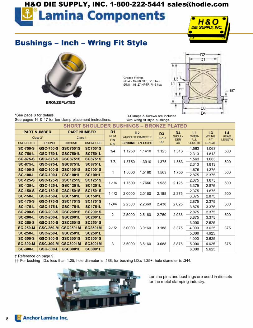
*See page 3 for details. See pages 16 & 17 for toe clamp installation instructions.
BRONZE PLATED SOLID STEEL
D4D2
L3
L1
L4
D1D5D3
.187
.188
Grease Fitting (incl.)
.75
STANDARD SHOULDER BUSHINGS � SOLID STEELPART NUMBER
Class 2 only*D1
NOMINALPIN
DIAMETER
D2WRING FIT D IAME TER
D3HEAD
OD
D4SHOULDER
OD
D5HEAD
ODGROOVE
L1OVERALLLENGTH
L3WRING
FITLENGTH
L4HEAD
LENGTHGROUND UNGROUND GROUND UNGROUND
GAC-750-SS AC-750-SS 3/4 1.1250 1.1410 1.219 1.313 1.125 2.063 .813 1.250GAC-100-SS AC-100-SS
1 1.5000 1.5160 1.656 1.750 1.5632.125 .875 1.250
GAC-100-SS2 AC-100-SS2 2.875 .875 2.000GAC-125-SS AC-125-SS
1-1/4 1.7500 1.7660 2.031 2.125 1.9382.625 1.125 1.500
GAC-125-SS2 AC-125-SS2 3.125 1.125 2.000GAC-150-SS AC-150-SS
1-1/2 2.0000 2.0160 2.281 2.375 2.1882.875 1.375 1.500
GAC-150-SS2 AC-150-SS2 3.375 1.375 2.000GAC-175-SS AC-175-SS
1-3/4 2.2500 2.2660 2.531 2.625 2.4383.125 1.625 1.500
GAC-175-SS2 AC-175-SS2 3.625 1.625 2.000GAC-200-SS AC-200-SS
2 2.5000 2.5160 3.031 3.125 2.9383.375 1.875 1.500
GAC-200-SS2 AC-200-SS2 3.875 1.875 2.000GAC-250-SS AC-250-SS 2-1/2 3.0000 3.0160 3.531 3.625 3.438 3.875 1.875 2.000
STANDARD SHOULDER BUSHINGS � BRONZE PLATEDPART NUMBER PART NUMBER D1
NOMPINDIA
D2WRING FIT
D IAMETER
D3HEAD
OD
D4SHOULDER
OD
D5HEAD
ODGROOVE
L1OVERALLLENGTH
L3WRING
FITLENGTH
L4HEAD
LENGTHClass 2* Class 1*
GROUND UNGROUND GROUND UNGROUND GROUND UNGROUND
GAC-750-S AC-750-S GAC7501S AC7501S 3/4 1.1250 1.1410 1.219 1.313 1.125 2.063 .813 1.250GAC-875-S AC-875-S GAC8751S AC8751S 7/8 1.3750 1.3910 1.469 1.563 1.375 2.125 .875 1.250GAC-100-S AC-100-S GAC1001S AC1001S
1 1.5000 1.5160 1.656 1.750 1.5632.125 .875
1.250GAC-100-L AC-100-L GAC1001L AC1001L 3.125 1.875GAC-125-S AC-125-S GAC1251S AC1251S
1-1/4 1.7500 1.7660 2.031 2.125 1.9382.625 1.125
1.500GAC-125-L AC-125-L GAC1251L AC1251S 3.625 2.125
GAC-150-SP N/A N/A N/A1-1/2 2.0000
N/A2.281 2.375 2.188
2.650 1.1501.500GAC-150-S AC-150-S GAC1501S AC1501S
2.01602.875 1.375
GAC-150-L AC-150-L GAC1501L AC1501L 3.875 2.375GAC-175-SP N/A N/A N/A
1-3/4 2.2500N/A
2.531 2.625 2.4382.875 1.375
1.500GAC-175-S AC-175-S GAC1751S AC1751S2.2660
3.125 1.625GAC-175-L AC-175-L GAC1751L AC1751L 4.125 2.625
GAC-200-SP N/A N/A N/A2 2.5000
N/A3.031 3.125 2.938
2.875 1.3751.500GAC-200-S AC-200-S GAC2001S AC2001S
2.51603.375 1.875
GAC-200-L AC-200-L GAC2001L AC2001L 4.375 2.875GAC-250-S AC-250-S GAC2501S AC2501S 2-1/2 3.0000 3.0160 3.531 3.625 3.438 3.875 1.875 2.000GAC-300-S AC-300-S GAC3001S AC3001S 3 3.6250 3.6410 4.281 4.375 4.188 3.875 1.875 2.000
Bushings � Inch � Wring Fit Style
D-Clamps & Screws are included with wring fit style bushings.
CL
Grease FittingsØ3/4� - 1/4-28 NTF, 5/16 hexØ7/8 -3� - 1/8-27 NPTF, 7/16 hex
H&O DIE SUPPLY, INC. 1-800-222-5441 [email protected]

5
SOLID BRONZE SELF-LUBRICATING
*See page 3 for details. See pages 16 & 17 for toe clamp installation instructions.
STANDARD SHOULDER BUSHINGS � SOLID BRONZEPART NUMBER PART NUMBER D1
NOMPINDIA
D2WRING FIT
DIAMETERD3
HEADOD
D4SHOUL-
DEROD
D5HEAD
ODGROOVE
L1OVER-
ALLLENGTH
L3WRING
FITLENGTH
L4HEAD
LENGTHClass 2* Class 1*
GROUND UNGROUND GROUND UNGROUND GROUND UNGROUND
GAC-750-SB AC-750-SB GAC7501SB AC7501SB 3/4 1.1250 1.1410 1.219 1.313 1.125 2.063 .813 1.250GAC-875-SB AC-875-SB GAC8751SB AC8751SB 7/8 1.3750 1.3910 1.469 1.563 1.375 2.125 .875 1.250GAC-100-SB AC-100-SB GAC1001SB AC1001SB 1 1.5000 1.5160 1.656 1.750 1.563 2.125 .875 1.250GAC-125-SB AC-125-SB GAC1251SB AC1251SB 1-1/4 1.7500 1.7660 2.031 2.125 1.938 2.625 1.125 1.500GAC-150-SB AC-150-SB GAC1501SB AC1501SB 1-1/2 2.0000 2.0160 2.281 2.375 2.188 2.875 1.375 1.500GAC-175-SB AC-175-SB GAC1751SB AC1751SB 1-3/4 2.2500 2.2660 2.531 2.625 2.438 3.125 1.625 1.500GAC-200-SB AC-200-SB GAC2001SB AC2001SB 2 2.5000 2.5160 3.031 3.125 2.938 3.375 1.875 1.500GAC-250-SB AC-250-SB GAC2501SB AC2501SB 2-1/2 3.0000 3.0160 3.531 3.625 3.438 3.875 1.875 2.000GAC-300-SB AC-300-SB GAC3001SB AC3001SB 3 3.6250 3.6410 4.281 4.375 4.188 3.875 1.875 2.000
STANDARD SHOULDER BUSHINGS � SELF LUBRICATINGPART NUMBER
Class 3 only*D1
NOMINALPIN
DIAMETER
D2WRING FIT DIAMETER
D3HEAD
OD
D4SHOULDER
OD
D5HEAD
ODGROOVE
L1OVERALLLENGTH
L3WRING
FITLENGTH
L4HEAD
LENGTHGROUND UNGROUND GROUND UNGROUND
GACB750S ACB750S 3/4 1.1250 1.1410 1.219 1.313 1.125 2.063 .813 1.250GACB100S ACB100S 1 1.5000 1.5160 1.656 1.750 1.563 2.125 .875 1.250GACB125S ACB125S 1-1/4 1.7500 1.7660 2.031 2.125 1.938 2.625 1.125 1.500GACB150S ACB150S 1-1/2 2.0000 2.0160 2.281 2.375 2.188 2.875 1.375 1.500GACB175S ACB175S 1-3/4 2.2500 2.2660 2.531 2.625 2.438 3.125 1.625 1.500GACB200S ACB200S 2 2.5000 2.5160 3.031 3.125 2.938 3.375 1.875 1.500GACB250S ACB250S 2-1/2 3.0000 3.0160 3.531 3.625 3.438 3.875 1.875 2.000GACB300S ACB300S 3 3.6250 3.6410 4.281 4.375 4.188 3.875 1.875 2.000
Note: Self-lubricating bronze with graphite bushings require initial lubrication with light oil. Periodic lubrication will extend thelife of self-lubricating bushings. Do not use grease.
D4D2
L3L1
L4
D1D5D3
.187
.188
Grease Fitting (Solid Bronze only)
.75
All Standard Shoulder Bushings (unless otherwise noted) are to be wring fit and held in place withtoe clamps and screws. This means that the bushing should be installed into the die shoe using awringing (circular) motion with the heel of the hand. Please see bore size information on page 18.
Bushings � Inch � Wring Fit Style
D-Clamps & Screws are included with wring fit style bushings.
Grease FittingsØ3/4 - 1/4-28 NTF, 5/16 hexØ7/8 - 1/8-27 NPTF, 7/16 hex
H&O DIE SUPPLY, INC. 1-800-222-5441 [email protected]

6
Press Fit bushings have tapered holes, larger at press fit end. This facilitates honing, sincethe bore will close up in a more nearly straight line when pressed in.While these bushings are precision finished on the O.D. a small amount of stock is left on the I.D. to allow forhoning because they are pressed fit type.
Toe clamps and screws are not provided with press fit shoulder bushings and they do not come with an LDSS grind.
*Please note!
D2
D1
L3
L4L1
D3
.750
GreaseFitting
SHOULDER BUSHING � PRESS FIT
PART NUMBER NOMINAL PINDIAMETER D1*
D2PRESS FITDIAMETER
D3HEADO.D.
L1OVERALLLENGTH
L4HEAD
LENGTH
L3PRESS FIT
LENGTH
RecommendedBore Size
8-1188-2500 1 1.00061.0003
1.50231.5018 1.688 2.500 1.313 1.188 1.5005
1.5000
10-1188-2688 1-1/4 1.25061.2503
1.75231.7518 1.938 2.688 1.500 1.188 1.7505
1.7500
12-1438-2938 1-1/2 1.50071.5004
2.00232.0018 2.188 2.938 1.500 1.438 2.0005
2.0000
Press Fit Shoulder Bushings allow for fast,easy installation. Eliminates the use ofclamps and screws.
Figure 8 oil grooves allow the lubricant to flow smoothlythroughout the bushing I.D.
BRONZE PLATED
Bushings � Inch � Pressed Fit Style
L1 D1
D2
BUSHINGS FOR LIFTER PINS � METRICPART
NUMBER D1 D2 L1
MBL-70453045 55
30MBL-704540 40MBL-704550 50
Grease Fittings3/4 - 1/4-28 NTF, 5/16 hex7/8 - 1/8-27 NPTF, 7/16 hex
H&O DIE SUPPLY, INC. 1-800-222-5441 [email protected]

7
LONG SHOULDER BUSHINGS � BRONZE PLATEDPART NUMBER D1
NOMPINDIA
D2WRING FIT DIAMETER
D3HEAD
OD
D4SHOUL-
DEROD
D5HEAD
ODGROOVE
L1OVER-
ALLLENGTH
L3WRING
FITLENGTH
L4HEAD
LENGTHClass 2* Class 1*
GROUND UNGROUND GROUND UNGROUND GROUND UNGROUND
GLAC-750-S LAC-750-S GLAC7501S LAC7501S 3/4 1.1250 1.1410 1.219 1.313 1.125 2.813 .813 2.000GLAC-875-S LAC-875-S GLAC8751S LAC8751S 7/8 1.3750 1.3910 1.469 1.563 1.375 3.000 .875 2.125GLAC-100-S LAC-100-S GLAC1001S LAC1001S 1 1.5000 1.5160 1.656 1.750 1.563 3.125 .875 2.250GLAC-125-S LAC-125-S GLAC1251S LAC1251S 1-1/4 1.7500 1.7660 2.031 2.125 1.938 3.500 1.125 2.375GLAC-150-S LAC-150-S GLAC1501S LAC1501S 1-1/2 2.0000 2.0160 2.281 2.375 2.188 4.125 1.375 2.750GLAC-150-SP N/A N/A N/A 1-1/2 2.0000 N/A 2.281 2.375 2.188 3.900 1.150 2.750GLAC-175-S LAC-175-S GLAC1751S LAC1751S 1-3/4 2.2500 2.2660 2.531 2.625 2.438 4.625 1.625 3.000GLAC-200-S LAC-200-S GLAC2001S LAC2001S 2 2.5000 2.5160 3.031 3.125 2.938 4.625 1.625 3.000GLAC-250-S LAC-250-S GLAC2501S LAC2501S 2-1/2 3.0000 3.0160 3.531 3.625 3.438 5.375 1.875 3.500GLAC-300-S LAC-300-S GLAC3001S LAC3001S 3 3.6250 3.6410 4.281 4.375 4.188 5.875 1.875 4.000
BRONZE PLATED SOLID STEEL
EXTRA-LONG SHOULDER BUSHINGS � BRONZE PLATEDPART NUMBER D1
NOMPINDIA
D2WRING FIT DIAMETER
D3HEAD
OD
D4SHOUL-
DEROD
D5HEAD
ODGROOVE
L1OVER-
ALLLENGTH
L3WRING
FITLENGTH
L4HEAD
LENGTHClass 2* Class 1*
GROUND UNGROUND GROUND UNGROUND GROUND UNGROUND
GXLAC-750-S XLAC-750-S GXLAC7501S XLAC7501S 3/4 1.1250 1.1410 1.219 1.313 1.125 3.563 .813 2.750GXLAC-875-S XLAC-875-S GXLAC8751S XLAC8751S 7/8 1.3750 1.3910 1.469 1.563 1.375 4.375 .875 3.500GXLAC-100-S XLAC-100-S GXLAC1001S XLAC1001S 1 1.5000 1.5160 1.656 1.750 1.563 4.375 .875 3.500GXLAC-125-S XLAC-125-S GXLAC1251S XLAC1251S 1-1/4 1.7500 1.7660 2.031 2.125 1.938 4.625 1.125 3.500GXLAC-150-S XLAC-150-S GXLAC1501S XLAC1501S 1-1/2 2.0000 2.0160 2.281 2.375 2.188 4.875 1.375 3.500
LONG & EXTRA LONG SHOULDER BUSHINGS � SOLID STEELPART NUMBER
Class 2 only*D1
NOMINALPIN
DIAMETER
D2WRING FIT DIAMETER
D3HEAD
OD
D4SHOULDER
OD
D5HEAD
ODGROOVE
L1OVERALLLENGTH
L3WRING FITLENGTH
L4HEAD
LENGTHGROUND UNGROUND GROUND UNGROUND
GXLAC-750-SS XLAC-750-SS 3/4 1.1250 1.1410 1.219 1.313 1.125 3.813 .813 3.000GXLAC-100-SS XLAC-100-SS 1 1.5000 1.5160 1.656 1.750 1.563 3.875 .875 3.000GXLAC-125-SS XLAC-125-SS 1-1/4 1.7500 1.7660 2.031 2.125 1.938 4.125 1.125 3.000GXLAC-150-SS XLAC-150-SS 1-1/2 2.0000 2.0160 2.281 2.375 2.188 4.375 1.375 3.000GXLAC-175-SS XLAC-175-SS 1-3/4 2.2500 2.2660 2.531 2.625 2.438 4.625 1.625 3.000 GLAC-200-SS LAC-200-SS 2 2.5000 2.5160 3.031 3.125 2.938 3.625 1.625 2.000GXLAC-200-SS XLAC-200-SS 2 2.5000 2.5160 3.031 3.125 2.938 4.625 1.625 3.000 GLAC-250-SS LAC-250-SS 2-1/2 3.0000 3.0160 3.531 3.625 3.438 5.375 1.875 3.500
D4D2D1
L1
L3
L4
D5D3
.187.188
Grease Fitting
.75
Bushings � Wring Fit Style
*See page 3 for details.See pages 16 & 17 for toe clamp placement instructions.
D-Clamps & Screwsare included withwring fit stylebushings.
Grease FittingsØ3/4 - 1/4-28 NTF, 5/16 hexØ7/8 - 1/8-27 NPTF, 7/16 hex
H&O DIE SUPPLY, INC. 1-800-222-5441 [email protected]
8
SHORT SHOULDER BUSHINGS � BRONZE PLATEDPART NUMBER PART NUMBER D1
NOMPINDIA
D2WRING FIT DIAMETER
D3HEAD
OD
D4SHOUL-
DEROD
L1OVER-
ALLLENGTH
L3WRING
FITLENGTH
L4HEAD
LENGTHClass 2* Class 1*
UNGROUND GROUND GROUND UNGROUND GROUND UNGROUND
SC-750-S GSC-750-S GSC7501S SC7501S3/4 1.1250 1.1410 1.125 1.313
1.563 1.063.500SC-750-L GSC-750-L GSC7501L SC7501L 2.313 1.813
SC-875-S GSC-875-S GSC8751S SC8751S 7/8 1.3750 1.3910 1.375 1.563
1.563 1.063.500SC-875-L GSC-875-L GSC8751L SC8751L 2.313 1.813
SC-100-S GSC-100-S GSC1001S SC1001S1 1.5000 1.5160 1.563 1.750
1.875 1.375.500SC-100-L GSC-100-L GSC1001L SC1001L 2.875 2.375
SC-125-S GSC-125-S GSC1251S SC1251S1-1/4 1.7500 1.7660 1.938 2.125
2.375 1.875.500SC-125-L GSC-125-L GSC1251L SC1251L 3.375 2.875
SC-150-S GSC-150-S GSC1501S SC1501S1-1/2 2.0000 2.0160 2.188 2.375
2.375 1.875.500SC-150-L GSC-150-L GSC1501L SC1501L 3.375 2.875
SC-175-S GSC-175-S GSC1751S SC1751S1-3/4 2.2500 2.2660 2.438 2.625
2.875 2.375.500SC-175-L GSC-175-L GSC1751L SC1751L 3.875 3.375
SC-200-S GSC-200-S GSC2001S SC2001S2 2.5000 2.5160 2.750 2.938
2.875 2.375.500SC-200-L GSC-200-L GSC2001L SC2001L 3.875 3.375
SC-250-S GSC-250-S GSC2501S SC2501S2-1/2 3.0000 3.0160 3.188 3.375
3.000 2.625.375SC-250-M GSC-250-M GSC2501M SC2501M 4.000 3.625
SC-250-L GSC-250-L GSC2501L SC2501L 5.000 4.625SC-300-S GSC-300-S GSC3001S SC3001S
3 3.5000 3.5160 3.688 3.8754.000 3.625
.375SC-300-M GSC-300-M GSC3001M SC3001M 5.000 4.625SC-300-L GSC-300-L GSC3001L SC3001L 6.000 5.625
BRONZE PLATED
Lamina pins and bushings are used in die setsfor the metal stamping industry.
*See page 3 for details.See pages 16 & 17 for toe clamp placement instructions.
Bushings � Inch � Wring Fit Style
D-Clamps & Screws are includedwith wring fit style bushings.
� Reference on page 9.�� For bushing I.D.s less than 1.25, hole diameter is .188; for bushing I.D.s 1.25+, hole diameter is .344.
Grease FittingsØ3/4 - 1/4-28 NTF, 5/16 hexØ7/8 - 1/8-27 NPTF, 7/16 hex
D2D1
.187
D3D4
L1L3
.75�
L4
��
H&O DIE SUPPLY, INC. 1-800-222-5441 [email protected]

9
*See page 3 for details.
SHORT SHOULDER BUSHINGS � SOLID BRONZEPART NUMBER PART NUMBER D1
NOMPINDIA
D2WRING FITDIAMETER
D3HEAD
OD
D4SHOUL-
DEROD
L1OVER-
ALLLENGTH
L3WRING
FITLENGTH
L4HEAD
LENGTHClass 2* Class 1*GROUND UNGROUND GROUND UNGROUND GROUND UNGROUND
GSC-750-SB SC-750-SB GSC7501SB SC7501SB 3/4 1.1250 1.1410 1.125 1.313
1.563 1.063.500
GSC-750-LB SC-750-LB GSC7501LB SC7501LB 2.313 1.813GSC-875-SB SC-875-SB GSC8751SB SC8751SB
7/8 1.3750 1.3910 1.375 1.5631.563 1.063
.500GSC-875-LB SC-875-LB GSC8751LB SC8751LB 2.313 1.813GSC-100-SB SC-100-SB GSC1001SB SC1001SB
1 1.5000 1.5160 1.563 1.7501.875 1.375
.500GSC-100-LB SC-100-LB GSC1001LB SC1001LB 2.875 2.375GSC-125-SB SC-125-SB GSC1251SB SC1251SB
1-1/4 1.7500 1.7660 1.938 2.1252.375 1.875
.500GSC-125-LB SC-125-LB GSC1251LB SC1251LB 3.375 2.875GSC-150-SB SC-150-SB GSC1501SB SC1501SB
1-1/2 2.0000 2.0160 2.188 2.3752.375 1.875
.500GSC-150-LB SC-150-LB GSC1501LB SC1501LB 3.375 2.875GSC-175-SB SC-175-SB GSC1751SB SC1751SB
1-3/4 2.2500 2.2660 2.438 2.6252.875 2.375
.500GSC-175-LB SC-175-LB GSC1751LB SC1751LB 3.875 3.375GSC-200-SB SC-200-SB GSC2001SB SC2001SB
2 2.5000 2.5160 2.750 2.9382.875 2.375
.500GSC-200-LB SC-200-LB GSC2001LB SC2001LB 3.875 3.375GSC-250-SB SC-250-SB GSC2501SB SC2501SB
2-1/2 3.0000 3.0160 3.188 3.3753.000 2.625
.375GSC-250-MB SC-250-MB GSC2501MB SC2501MB 4.000 3.625GSC-250-LB SC-250-LB GSC2501LB SC2501LB 5.000 4.625GSC-300-SB SC-300-SB GSC3001SB SC3001SB
3 3.5000 3.5160 3.688 3.8754.000 3.625
.375GSC-300-MB SC-300-MB GSC3001MB SC3001MB 5.000 4.625GSC-300-LB SC-300-LB GSC3001LB SC3001LB 6.000 5.625GSC-375-B SC-375-B N/A N/A 3-3/4 4.5000 4.5160 4.688 4.875 7.000 6.625 .375GSC-450-B SC-450-B N/A N/A 4-1/2 5.5000 5.5160 5.688 5.875 8.000 7.625 .375
SOLID BRONZE
�Bushings of 2.50� diameter and larger have 1.25� dimensions.�� For bushing I.D.s less than 1.25, hole diameter is .188; for bushing I.D.s 1.25+, hole diameter is .344.
See pages 16 & 17 for toe clamp placement instructions.
Bushings � Inch � Wring Fit Style
All Short Shoulder Bushings (unless otherwise noted) are to be wring fit and held in place with toeclamps & screws. This means the bushing should be installed into the die shoe using a wringing(circular) motion with the heel of the hand. Please see bore size information on page 18.
Grease FittingsØ3/4 - 1/4-28 NTF, 5/16 hexØ7/8 - 1/8-27 NPTF, 7/16 hex
D2D1
.187
D3D4
L1L3
.75�
L4
��
D-Clamps & Screws are includedwith wring fit style bushings.
H&O DIE SUPPLY, INC. 1-800-222-5441 [email protected]

10
*See page 3 for details. See pages 16 & 17 for toe clamp placement instructions.
SHORT SHOULDER BUSHINGS � SELF-LUBRICATINGPART NUMBER
Class 3 only*D1
NOMPINDIA
D2WRING FIT DIAMETER
D3HEAD
OD
D4SHOULDER
OD
L1OVERALLLENGTH
L3WRING
FITLENGTH
L4HEAD
LENGTHGROUND UNGROUND GROUND UNGROUND
GSCB750S SCB750S3/4 1.1250 1.1410 1.125 1.313
1.563 1.063.500GSCB750L SCB750L 2.313 1.813
GSCB875S SCB875S7/8 1.3750 1.3910 1.375 1.563
1.563 1.063.500GSCB875L SCB875L 2.313 1.813
GSCB100S SCB100S1 1.5000 1.5160 1.563 1.750
1.875 1.375.500GSCB100L SCB100L 2.875 2.375
GSCB125S SCB125S1-1/4 1.7500 1.7660 1.938 2.125
2.375 1.875.500GSCB125L SCB125L 3.375 2.875
GSCB150S SCB150S1-1/2 2.0000 2.0160 2.188 2.375
2.375 1.875.500GSCB150L SCB150L 3.375 2.875
GSCB175S SCB175S1-3/4 2.2500 2.2660 2.438 2.625
2.875 2.375.500GSCB175L SCB175L 3.875 3.375
GSCB200S SCB200S2 2.5000 2.5160 2.750 2.938
2.875 2.375.500GSCB200L SCB200L 3.875 3.375
GSCB250S SCB250S2-1/2 3.0000 3.0160 3.188 3.375
3.000 2.625.375GSCB250M SCB250M 4.000 3.625
GSCB250L SCB250L 5.000 4.625GSCB300X SCB300X
3 3.5000 3.5160 3.688 3.875
3.000 2.625
.375GSCB300S SCB300S 4.000 3.625GSCB300M SCB300M 5.000 4.625GSCB300L SCB300L 6.000 5.625GSCB375S SCB375S 3-3/4 4.5000 4.5160 4.688 4.875 7.000 6.625 .375GSCB450S SCB450S 4-1/2 5.5000 5.5160 5.688 5.875 8.000 7.625 .375
Self-lubricating bronze with graphite bushings require initial lubrication with light oil. Periodic lubrication will extend the life ofself-lubricating bushings. Do not use grease.
D2D1
D3D4
L1L3
L4
.187
BRONZE with SELF-LUBRICATINGGRAPHITE PLUGS
Bushings � Inch � Wring Fit Style
D-Clamps & Screws areincluded with wring fitstyle bushings.
H&O DIE SUPPLY, INC. 1-800-222-5441 [email protected]

11
AUTOMOTIVE METRIC
NAAMS STANDARD
Evenly distributed graphite covers 20-30% of thesliding surface.
Graphite is positioned to ensure overlapping inthe slide direction.
See page 17 for Toe Clamp information and 18for bore sizes.
NOTE:
D4D3
L3L1
6
D1D2
These short shoulder bushings are made espe-cially for automotive stamping companies. Theyconform to the standards agreed to by the NorthAmerican Automotive Metric Standards group.
BRONZE with SELF-LUBRICATINGGRAPHITE PLUGS
SHORT-SHOULDER BUSHINGS SELF-LUBRICATING - NAAMS
PART NUMBERD1
NOMINAL PINDIAMETER
D1TOL H6
D2WRING FITDIAMETER
D2Tol g6 D3 D4
L1OVERALLLENGTH
L3WRING FITLENGTH
No. TOECLAMPS &SCREWS
G612540 25 +.013+.000 32 �.009
�.025 32 40 40 30
3
G613250 32 +.016+.000 40 -.009
-.025 40 50 50 40
G614063 40 +.016+.000 50 -.009
-.025 50 63 63 50
G615071 50 +.016+.000 63 -.010
-.029 63 71 71 56
G616380 63 +.019+.000 80 -.010
-.029 80 90 80 63
G618010 80 +.019+.000 100 -.012
-.034 100 112 100 80
G611012 100 +.022+.000 125 -.014
-.039 125 140 125 106
G611114 115 +.022+.000 140 -.014
-.039 140 155 140 120
G611216 125 +.025+.000 160 -.014
-.039 160 180 160 132
See page 17 for toe clamp placement instructions.
Bushings � Metric � Wring Fit Style
G720000C Clamps &Screws are included withNAAMS wring fit stylebushings.
H&O DIE SUPPLY, INC. 1-800-222-5441 [email protected]

12
AUTOMOTIVE METRIC
NAAMS STANDARD
Evenly distributed graphite covers 20-30% of thesliding surface.
Graphite is positioned to ensure overlapping inthe slide direction.
See page 18 for bore size information.
NOTE:
These pad bushings are made especially for automotive stamp-ing companies. They conform to the standards agreed to by theNorth American Automotive Metric Standards group.
A full complement of flat productsis also available from theLamina Components line.
SELF-LUBRICATING PAD BUSHINGS - NAAMS
PART NUMBERD1
NOMINAL PINDIAMETER
D1TOLc9
D2WRING FITDIAMETER
D2TOLg6
D4 L1OVERALL LENGTH
G712540 25 +.162+.110 32 �.009
�.025 40 40
G713250 32 +.182+.120 40 -.009
-.025 50 50
G714055 40 +.182+.120 50 -.009
-.025 63 55
G715063 50 +.192+.130 63 -.010
-.029 71 63
G716375 63 +.214+.140 80 -.010
-.029 90 75
G718090 80 +.224+.150 100 -.012
-.034 112 90
G711011 100 +.257+.170 125 -.014
-.039 140 115
G711213 125 +.300+.200 160 -.014
-.039 180 138
D4
6
L1
D1
D2
BRONZE with SELF LUBRICATINGGRAPHITE PLUGS
See page 17 for toe clamp installation instructions.
Bushings � Metric
H&O DIE SUPPLY, INC. 1-800-222-5441 [email protected]
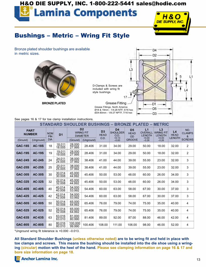
13
Bronze plated shoulder bushings are availablein metric sizes.
D4D2
L3
D1D5D3
L1
L4
Grease Fitting
55
BRONZE PLATED
See pages 16 & 17 for toe clamp installation instructions.
Bushings � Metric � Wring Fit Style
All Standard Shoulder Bushings (unless otherwise noted) are to be wring fit and held in place withtoe clamps and screws. This means the bushing should be installed into the die shoe using a wring-ing (circular) motion with the heel of the hand. Please see clamping information on page 16 & 17 andbore size information on page 18.
D-Clamps & Screws areincluded with wring fitstyle bushings.
*Unground wring fit tolerance is +0.000 �0.013.
STANDARD SHOULDER BUSHINGS � BRONZE PLATED � METRICPART
NUMBER NOMPINDIA
D1
D2WRING FITDIAMETER
D3HEADO.D.
D4SHOULDER
O.D.+0.13�0.00
D5HEAD
ODGROOVE
L1OVERALLLENGTH
+0.00�0.26
L3WRING FIT
LENGTH+0.00�0.26
L4HEAD
LENGTH
NO.CLAMPS
&SCREWS(Ground) (Unground) (Ground) (Unground)
GAC-18S AC-18S 18 18.01118.005
28.00027.995 28.406 31.00 34.00 29.00 50.00 18.00 32.00 2
GAC-19S AC-19S 19 19.01119.005
28.00027.995 28.406 31.00 34.00 29.00 50.00 18.00 32.00 2
GAC-24S AC-24S 24 24.01124.005
38.00037.992 38.406 41.00 44.00 39.00 55.00 23.00 32.00 3
GAC-25S AC-25S 25 25.01125.005
38.00037.992 38.406 41.00 44.00 39.00 55.00 23.00 32.00 3
GAC-30S AC-30S 30 30.01430.008
45.00044.992 45.406 50.00 53.00 48.00 60.00 26.00 34.00 3
GAC-32S AC-32S 32 32.01432.008
45.00044.992 45.406 50.00 53.00 48.00 60.00 26.00 34.00 3
GAC-40S AC-40S 40 40.01440.008
54.00053.992 54.406 60.00 63.00 58.00 67.00 30.00 37.00 3
GAC-42S AC-42S 42 42.01442.008
54.00053.992 54.406 60.00 63.00 58.00 67.00 30.00 37.00 3
GAC-50S AC-50S 50 50.01450.008
65.00064.992 65.406 76.00 79.00 74.00 75.00 35.00 40.00 4
GAC-52S AC-52S 52 52.01452.008
65.00064.992 65.406 76.00 79.00 74.00 75.00 35.00 40.00 4
GAC-63S AC-63S 63 63.01663.010
81.00080.990 81.406 89.00 92.00 87.00 88.00 46.00 42.00 4
GAC-80S AC-80S 80 80.01680.010
100.00099.990 100.406 108.00 111.00 106.00 98.00 46.00 52.00 4
17
Grease Fittings, North AmericaØ18 & 19mm - 1/4-28 NTF, 5/16 hexØ24-80mm - 1/8-27 NPTF, 7/16 hex
H&O DIE SUPPLY, INC. 1-800-222-5441 [email protected]

14
D4D2D1
L3
L1
L4
D5D3
Grease Fitting
55
17
See pages 16 & 17 for toe clamp placement instructions.
Bushings � Metric � Wring Fit Style
All Standard Shoulder Bushings (unless otherwise noted) are to be wring fit and held in place withtoe clamps and screws. This means that the bushing should be installed into the die shoe using awringing (circular) motion with the heel of the hand. Please see clamping information on page 16 &17 and bore size information on page 18.
D-Clamps & Screws areincluded with wring fitstyle bushings.
*Unground wring fit tolerance is +0.000 �0.013.
LONG & EXTRA LONG SHOULDER BUSHINGS � BRONZE PLATED � METRICPART NUMBER NOM
PINDIA
D1D2
WRING FIT O.D. D3HEADO.D.
D4SHOULDER
O.D.+0.13�0.00
D5HEAD
ODGROOVE
L1OVERALLLENGTH
+0.00�0.26
L3WRING-FITLENGTH
+0.00�0.26
L4HEAD
LENGTH
NO.CLAMPS
&SCREWS(Ground) (Unground) (Ground) (Unground)
GLAM-18FGLAC-18S
LAM-18FLAC-18S 18 18.011
18.00528.00027.995 28.406 31.00 34.00 29.00 69.00
70.0026.0018.00
43.0052.00 2
GLAM-19FGLAC-19S
LAM-19FLAC-19S 19 19.011
19.00528.00027.995 28.406 31.00 34.00 29.00 69.00
70.0026.0018.00
43.0052.00 2
GLAM-24FGLAC-24S
LAM-24FLAC-24S 24 24.011
24.00538.00037.992 38.406 41.00 44.00 39.00 80.00
80.0032.0023.00
48.0057.00 3
GLAM-25FGLAC-25S
LAM-25FLAC-25S 25 25.011
25.00538.00037.992 38.406 41.00 44.00 39.00 80.00
80.0032.0023.00
48.0057.00 3
GLAM-30FGLAC-30S
LAM-30FLAC-30S 30 30.014
30.00845.00044.992 45.406 50.00 53.00 48.00 89.00
90.0036.0026.00
53.0064.00 3
GLAM-32FGLAC-32S
LAM-32FLAC-32S 32 32.014
32.00845.00044.992 45.406 50.00 53.00 48.00 89.00
90.0036.0026.00
53.0064.00 3
GLAM-40FGLAC-40S
LAM-40FLAC-40S 40 40.014
40.00854.00053.992 54.406 60.00 63.00 58.00 99.00
100.00 46.0030.00
53.0070.00 3
GLAM-42FGLAC-42S
LAM-42FLAC-42S 42 42.014
42.00854.00053.992 54.406 60.00 63.00 58.00 99.00
100.00 46.0030.00
53.0070.00 3
GLAM-50FGLAC-50S
LAM-50FLAC-50S 50 50.014
50.00865.00064.992 65.406 76.00 79.00 74.00 109.00
110.00 56.0035.00
53.0075.00 4
GLAM-52FGLAC-52S
LAM-52FLAC-52S 52 52.014
52.00865.00064.992 65.406 76.00 79.00 74.00 109.00
110.00 56.0035.00
53.0075.00 4
GLAM-63FGLAC-63S
LAM-63FLAC-63S 63 63.016
63.01081.00080.990 81.406 89.00 92.00 87.00 129.00
128.00 66.0046.00
63.0082.00 4
GLAM-80FGLAC-80S
LAM-80FLAC-80S 80 80.016
80.010100.00099.990 100.406 108.00 111.00 106.00 149.00
148.00 76.0046.00
73.00102.00 4
Grease Fittings, North AmericaØ18 & 19mm - 1/4-28 NTF, 5/16 hexØ24-80mm - 1/8-27 NPTF, 7/16 hex
H&O DIE SUPPLY, INC. 1-800-222-5441 [email protected]

15
*Ø4.76 for bushings withnom. I.D.s between 18 &32mm.
*Ø8.73 for bushings withnom. I.D.s between 40 &80mm.
SHORT SHOULDER BUSHINGS � BRONZE PLATED � METRIC
PART NUMBERNOMPINDIA
D1D2
WRING FIT DIAMETER D3HEADO.D.
D4SHOULDER
OD+0.13�0.00
L1OVERALLLENGTH
+0.00�0.26
L3WRING
FITLENGTH
+0.00�0.26
H1LUBEHOLE
CENTER
NO.CLAMPS &SCREWSGROUND UNGROUND GROUND *UNGROUND
GSC-18S SC-18S 18 18.011
18.00528.00027.995 28.406 29.00 34.00
31.00 18.008.00 2
GSCL-18F SCL-18F 49.00 36.00 GSC-19S SC-19S
19 19.01119.005
28.00027.995 28.406 29.00 34.00
31.00 18.008.00 2
GSCL-19F SCL-19F 49.00 36.00 GSC-24S SC-24S
24 24.01124.005
38.00037.992 38.406 39.00 44.00
36.00 23.0012.00 3
GSCL-24F SCL-24F 55.00 42.00 GSC-25S SC-25S
25 25.01125.005
38.00037.992 38.406 39.00 44.00
36.00 23.0012.00 3 GSCL-25F SCL-25F 55.00 42.00
GSC-30S SC-30S 30 30.014
30.00845.00044.992 45.406 48.00 53.00
43.00 30.0015.00 3 GSCL-30F SCL-30F 59.00 46.00
GSC-32S SC-32S 32 32.014
32.00845.00044.992 45.406 48.00 53.00
43.00 30.0015.00 3 GSCL-32F SCL-32F 59.00 46.00
GSC-40S SC-40S 40 40.014
40.00854.00053.992 54.406 58.00 63.00
49.00 36.0019.00 3 GSCL-40F SCL-40F 67.00 54.00
GSC-42S SC-42S42 42.014
42.00854.00053.992 54.406 58.00 63.00
49.00 36.0019.00 3
GSCL-42F SCL-42F 67.00 54.00 GSC-50S SC-50S
50 50.01450.008
65.00064.992 65.406 74.00 79.00
59.00 46.0019.00 4
GSCL-50F SCL-50F 75.00 62.00 GSC-52S SC-52S
52 52.01452.008
65.00064.992 65.406 74.00 79.00
59.00 46.0019.00 4
GSCL-52F SCL-52F 75.00 62.00 GSC-63S SC-63S
63 63.01663.010
81.00080.990 81.406 87.00 92.00
74.00 61.0019.00 4 GSCL-63F SCL-63F 89.00 76.00
GSC-80S SC-80S 80 80.01680.010
100.00099.990 100.406 106.00 111.00 89.00 76.00 19.00 4
*Unground wring fit tolerance is +0.000 �0.013.
See pages 16 & 17 for toe clamp placement instructions.
Bushings � Metric � Wring Fit Style
All Standard Shoulder Bushings (unless otherwise noted) are to be wring fit and held in place withtoe clamps and screws. This means that the bushing should be installed into the die shoe using awringing (circular) motion with the heel of the hand. Please see clamping information on page 16 &17 and bore size information on page 18.
D-Clamps & Screws areincluded with wring fitstyle bushings.
D2D1
D3D4
L1L3
13
5H1
*
Grease Fittings, North AmericaØ18 & 19mm - 1/4-28 NTF, 5/16 hexØ24-80mm - 1/8-27 NPTF, 7/16 hex
H&O DIE SUPPLY, INC. 1-800-222-5441 [email protected]

16
Toe Clamp Information for Inch & Metric Plain Bearing Die Bushings
REPLACEMENT KITS CLAMPS & SCREWSD-Clamps
PARTNUMBER
Nom PinDiameters
# Clamps& Screws
per Kit
No. ofKits
NeededPART
NUMBERNom Pin
Diameters# Clamps& Screws
per Kit
No. ofKits
NeededCSK100002 5/8 - 7/8 2 1 CSK10052 18 - 19 2 1CSK100003 1 - 1-3/4 3 1 CSK10053 24 - 42 3 1CSK100002 2 - 2-1/2 2 2 CSK10052 50 - 80 2 2CSK100003 3 - 4-1/2 3 2
X40-ClampsCSK200002 5/8 - 7/8 2 1 CSK20052 18 - 19 2 1CSK200003 1 - 1-3/4 3 1 CSK20053 24 - 42 3 1CSK200002 2 - 2-1/2 2 2 CSK20052 50 - 80 2 2CSK200003 3 - 4-1/2 3 2
Bolt CircleDiameter
Drawing above can refer to eitherD-Clamps or X-40-Clamps
CLAMP & SCREW PLACEMENTINCH METRIC
BushingID
#Provided
Bolt Circle Diameter BushingID
AC,LAM,LAC, SC
#Provided
Bolt Circle DiameterD-Clamps X-40 Clamps
D-Clamps X-40 ClampsAC, LAC,XLAC SC LMB AC, LAC,
XLAC SC LMB
.625 2 N/A N/A 1.531 N/A N/A 1.644 18 2 45 47.18
.750 2 1.719 1.719 1.719 1.831 1.831 1.891 19 2 45 47.18
.875 2 1.969 1.969 N/A 2.081 2.081 N/A 24 3 55 57.181.00 3 2.156 2.156 2.156 2.269 2.269 2.269 25 3 55 57.181.25 3 2.531 2.531 2.531 2.644 2.644 2.644 30 3 64 66.181.50 3 2.781 2.781 2.781 2.894 2.894 2.894 32 3 64 66.181.75 3 3.031 3.031 3.031 3.144 3.144 3.144 40 3 74 76.182.00 4 3.531 3.344 3.344 3.644 3.456 3.456 42 3 74 76.182.50 4 4.031 3.781 4.031 4.174 3.894 4.174 50 4 90 92.183.00 6 4.781 4.281 4.531 4.944 4.424 4.694 52 4 90 92.183.75 6 5.281 5.281 5.281 5.281 5.424 5.444 63 4 103 105.944.50 6 6.281 6.281 6.281 6.281 6.444 6.444 80 4 122 125.45
.547
.188
.278
.563
D-Clamp &BHC031075 Screw
(5/16-18 x 3/4�)
.266
X-40-Clamp &SHC031075 Screw
(5/16-18 x 3/4�)
D-Clamp & F010810 Metric Screw
(M8 x 1.25-20mm)
14.30
13.89
7.06
4.786.76
Toe Clamp Dimensions
.688
.367.188
X-40-Clamp &F010810 Metric Screw
(M8 x 1.25-20mm)
17.48
9.324.78
.389.328
.771
9.888.3319.58
H&O DIE SUPPLY, INC. 1-800-222-5441 [email protected]

17
BUSHING CLAMPING PROCEDURESAUTOMOTIVE METRICNAAMS STANDARD
M8 x 1.25 Tap(3) Holes equallyspaced
D1 D4 B.C.(D4 + 18)
25 40 5832 50 6840 63 8150 71 8963 90 108 80 112 130
100 140 158 115 155 173 125 180 198
24.6
18.9
Clamp Part No:G720000C M8 x 1.25 x 20 Long
613
D1 (ID of Bushing)D4(O.D. of Bushing
Shoulder)
B.C. = D4 + 18Bushings will be supplied with (3) toeclamps and (3) screws - M8. Screwsmust engage 16mm minimum deep intodie shoe.
NOTES & SPECIFICATION:
BOLT CIRCLEDIAMETERS
DEMOUNTABLEBALL BEARING
BUSHINGSNominal
Bushing DiameterBolt CircleDiameter
1 2.4381-1/4 2.8131-1/2 3.1251-3/4 3.438
2 4.0002-1/2 4.500
3 5.000DEMOUNTABLE
BALL BEARING & PLAINBEARING PINS
Nominal PinDiameter
Bolt CircleDiameter
1 1.7501-1/4 2.0001-1/2 2.2501-3/4 2.625
2 2.8752-1/2 3.375
3 3.875KEYLESS DEMOUNTABLEBALL BEARING BUSHINGS
NominalBushing Diameter
Bolt CircleDiameter
1 2.6251-1/4 2.8751-1/2 3.3751-3/4 3.625
2 4.1252-1/2 4.625
3 5.250KEYLESS DEMOUNTABLE
BALL BEARING PINSNominal Pin
DiameterBolt CircleDiameter
1 1.6251-1/4 1.9691-1/2 2.2501-3/4 2.594
2 2.8842-1/2 3.344
3 3.844
Toe Clamp Information for Inch & Metric Demountable Components
BALL-BEARING DEMOUNTABLE COMPONENT CLAMP ARRANGEMENTS
NOM.PINDIA.
STANDARDLEFT - RIGHT FEED
FRONT to BACK FEED(Center Post Die Sets) ROUND DIES
1,11/4,&
11/2
13/4,2,
21/2&3
13/4,2,
21/2&3
13/4,2,
21/2&3
FEED
35°
55°
35°
FEED
120°
FEED
50°
40°
40°
FEED45°45°
120°90°
FEED
35°
35°
FEED
40° 40°
FEED
45°120°
10°70°
90°
5° 80°
H&O DIE SUPPLY, INC. 1-800-222-5441 [email protected]

18
DEFINITIONS OF MOUNTING PROCEDURESPins and bushings require specific mountingprocedures. By following these proceduresthe components should give maximum lifeand reduce downtime due to improperalignment, breakage and uneven wear.
Pressed Fit � The component is installed in aninterference condition: the bore size is smallerthan the pressed fit portion of the component.
Bushings that require a pressed fitshould never be frozen or hammered. Theyshould be forced into place using a hydraulicpress or other proper tooling. Improper meth-ods can permanently change the tolerance ofthe component.
Pins can be forced into place using ahydraulic press; or the pins can be frozen andpressed into place. Lamina does not recom-mend hammering pins into place. Hammer-ing can cause the pins to �mushroom� or
expand on the pin end resulting in perma-nent distortion of the component.
Tap Fit � The component should be tappedusing a soft hammer into the bored hole andsecured with toe clamps.
Wring Fit � The component should be installedusing a wringing (circular) motion with the heelof the hand. Wring fit components are to be heldin place with toe clamps, retaining rings or plates.
Nom.Pin
Diameter
StandardInch GAC
GLACGXLAC &GSC StyleBushings
StandardMetric
GAC,GLAC,GLAM &
GSC StyleBushings
ShortShoulder
& PadBushingsNAAMS
BushingLinerFor
RemovablePin
StraightGuide Pins
InchTN & ATN
StraightGuide Pins
MetricTN
StraightGuide Pins
InchTPC
Demount-able Inch
Guide Pins
StandardMetric
Guide Pins
RECOMMENDED BORE SIZES for PLAIN BEARING PINS & BUSHINGS
Wring Fit Wring Fit Wring Fit Pressed Fit Pressed Fit Pressed Fit Pressed Fit Tap Fit Tap Fit
3/4�
7/8�
1�
1-1/4�
1-1/2�
1-3/4�
2�
2-1/2�
3�
3�
3-3/4�
4-1/2�
18mm
19mm
24mm
25mm
30mm
32mm
40mm
42mm
50mm
52mm
63mm
80mm
100mm
115mm
125mm
GSC Only
1.12551.12501.37551.37501.50051.50001.75051.75002.00052.00002.25052.25002.50052.50003.00053.00003.50053.50003.62553.62504.50054.50005.50055.5000
28.01328.00028.01328.00038.01638.00038.01638.00045.01645.00045.01645.00054.01954.00054.01954.00065.01965.00065.01965.00081.02281.000100.022100.000
N/A
N/A
N/A
N/A
N/A
N/A
N/A
N/A
40.02540.00050.02550.000
N/A
63.03063.000
N/A80.03080.000100.035100.000125.040125.000140.040140.000160.040160.000
N/A N/A
N/A
N/A
N/A
18.98018.959
24.98024.959
31.97531.950N/A
N/A
N/A
N/A
N/A
N/A
N/A
N/A
N/A
N/A N/A
18.98018.959
24.98024.959
31.97531.950
N/A
N/A
N/A
N/A
N/A
N/A
N/A
N/A
N/A
N/A
N/A
N/A
N/A
N/A
N/A N/A
N/A
N/A
N/A N/A
N/A
1.49881.49831.74881.74831.99831.99782.24832.24782.49832.49782.99832.9978
0.99850.99801.24801.24751.49801.49751.74801.74751.99751.99702.49752.4970
3.49833.4978
2.99752.9970
0.74850.7480
N/A N/A
N/A N/A
2.99953.00003.74953.75004.49954.5000
0.75050.75000.87550.87501.00051.00001.25051.25001.50051.50001.75051.75001.99952.00002.49952.5000
1.00051.00001.25051.25001.50051.50001.75051.75002.00052.00002.50052.5000
N/A
N/A
N/A N/A
N/A
N/A
N/A
N/A
N/A
N/A
N/A
N/A
N/A
N/A
32.06032.05040.05040.060
50.06050.050
63.07063.06080.07280.062100.083100.073115.035115.000125.040125.000
N/A
N/A
N/A
N/A
N/A
N/A
N/A
32.02532.00040.02540.000
50.02550.000
63.03063.00080.03080.000100.035100.000115.035115.000125.040125.000
Guide Pinswith
ShouldersNAAMS
Tap Fit
StraightGuide Pins
NAAMS
Pressed Fit
3.00053.0000
N/A
N/A
H&O DIE SUPPLY, INC. 1-800-222-5441 [email protected]

19
D1D2
L1
L2
ChamferFigure 8Oil Groove
Sharp Corner(Both Ends)
!!!!! For Machine Tools, Fixtures, etc.!!!!! Straight Design, Wiper type!!!!! Lamina-Bronze on steel provides
longer wearing running fits!!!!! Plating thickness .005�.007 per
side!!!!! No reaming or honing after press
fitting bearing.
HEAT TREATED
BEARINGS � RUNNING FIT � HARDENED
PARTNUMBER
D1I.D.
+.0005�.0000
D2O.D.+.0004�.0000
RECOM-MENDED
BORE SIZE+.0005�.0000
LLENGTH
PARTNUMBER
D1I.D.
+.0005�.0000
D2O.D.+.0004*�.0000
RECOM-MENDED
BORE SIZE+.0005�.0000
LLENGTH
625-x-75-RFB .6270 1.0014 .9995
.75 175-x-175-RFB
1.7530 2.2518 2.2495
1.75625-x-100-RFB 1.00 175-x-200-RFB 2.00625-x-125-RFB 1.25 175-x-250-RFB 2.50750-x-75-RFB
.7525 1.1264 1.1245
.75 175-x-300-RFB 3.00750-x-100-RFB 1.00 175-x-350-RFB 3.50750-x-125-RFB 1.25 200-x-200-RFB
2.0035 2.5018 2.4995
2.00750-x-150-RFB 1.50 200-x-250-RFB 2.50100-x-100-RFB
1.0025 1.3764 1.3745
1.00 200-x-300-RFB 3.00100-x-125-RFB 1.25 200-x-350-RFB 3.50100-x-150-RFB 1.50 200-x-400-RFB 4.00100-x-175-RFB 1.75 250-x-250-RFB
2.5035 3.2518 3.2490
2.50100-x-200-RFB 2.00 250-x-300-RFB 3.00125-x-125-RFB
1.2530 1.7516 1.7495
1.25 250-x-350-RFB 3.50125-x-150-RFB 1.50 250-x-400-RFB 4.00125-x-175-RFB 1.75 250-x-450-RFB 4.50125-x-200-RFB 2.00 250-x-500-RFB 5.00125-x-250-RFB 2.50 300-x-300-RFB
3.0040
+.0005*�.0000
3.7520
3.7490
3.00150-x-150-RFB
1.5030 2.0016 1.9995
1.50 300-x-350-RFB 3.50150-x-175-RFB 1.75 300-x-400-RFB 4.00150-x-200-RFB 2.00 300-x-450-RFB 4.50150-x-250-RFB 2.50 300-x-500-RFB 5.00150-x-300-RFB 3.00 300-x-600-RFB 6.00
Bearings � Pressed Fit
Bearings for Radial or Linear Applications
*This diameter only.
H&O DIE SUPPLY, INC. 1-800-222-5441 [email protected]

20
D1D2
L1
L2
ChamferFigure 8 OilGroove
Sharp Corner(Both Ends) !!!!! For Machine Tools, Fixtures, etc.
!!!!! Straight Design, Wiper type!!!!! Lamina-Bronze on steel provides
longer wearing running fits!!!!! Plating thickness .005�.007 per side!!!!! No reaming or honing after press
fitting bearing.!!!!! Flash-plated O.D. prevents scoring
when pressing bearing in and outNON-HEAT TREATED
Bearings for Radial or Linear Applications
BEARINGS � RUNNING FIT � NON-HEAT-TREATED
PARTNUMBER
D1I.D.
+.0005�.0000
D2O.D.+.0004�.0000
RECOM-MENDED
BORE SIZE+.0005�.0000
LLENGTH
PARTNUMBER
D1I.D.
+.0005�.0000
D2O.D.+.0004�.0000
RECOM-MENDED
BORE SIZE+.0005�.0000
LLENGTH
SRFB-75-x-75
.7525 1.1265 1.1245
.75 SRFB-175-x-200
1.7530 2.1265 2.1245
2.00SRFB-75-x-100 1.00 SRFB-175-x-225 2.25SRFB-75-x-125 1.25 SRFB-175-x-250 2.50SRFB-75-x-150 1.50 SRFB-175-x-300 3.00SRFB-100-x-75
1.0025 1.3765 1.3745
.75 SRFB-200-x-100
2.0035 2.3765 2.3745
1.00SRFB-100-x-100 1.00 SRFB-200-x-125 1.25SRFB-100-x-125 1.25 SRFB-200-x-150 1.50SRFB-100-x-150 1.50 SRFB-200-x-200 2.00SRFB-100-x-175 1.75 SRFB-200-x-250 2.50SRFB-100-x-200 2.00 SRFB-200-x-300 3.00SRFB-125-x-75
1.2530 1.6265 1.6545
.75 SRFB-200-x-350 3.50SRFB-125-x-100 1.00 SRFB-200-x-400 4.00SRFB-125-x-125 1.25 SRFB-250-x-125
2.5035 2.8765 2.8745
1.25SRFB-125-x-150 1.50 SRFB-250-x-150 1.50SRFB-125-x-175 1.75 SRFB-250-x-200 2.00SRFB-125-x-200 2.00 SRFB-250-x-250 2.50SRFB-125-x-250 2.50 SRFB-250-x-300 3.00SRFB-150-x-75
1.5030 1.8765 1.8745
.75 SRFB-250-x-350 3.50SRFB-150-x-100 1.00 SRFB-250-x-400 4.00SRFB-150-x-125 1.25 SRFB-250-x-500 5.00SRFB-150-x-150 1.50 SRFB-300-x-150
3.0040
+.0005*�.0000
3.5020 3.4995
1.50SRFB-150-x-175 1.75 SRFB-300-x-200 2.00SRFB-150-x-200 2.00 SRFB-300-x-250 2.50SRFB-150-x-250 2.50 SRFB-300-x-300 3.00SRFB-175-x-100
1.7530 2.1265 2.1245
1.00 SRFB-300-x-350 3.50SRFB-175-x-125 1.25 SRFB-300-x-400 4.00SRFB-175-x-150 1.50 SRFB-300-x-500 5.00SRFB-175-x-175 1.75 SRFB-300-x-600 6.00
Bearings � Pressed Fit
*This diameter only.
H&O DIE SUPPLY, INC. 1-800-222-5441 [email protected]

21
Wiper Head
L1
D1D2
D1D2
.02 Flat
30°.187
Sharp Corner(Both Ends)
L1
D4
L5
L3
D3
.250 H
Wiper Bushings � Wring Fit Style
Bearings � Pressed Fit
! Used in Transfer Machinery! Bronze Plated Steel for strength
and lubricity
Guide Bar Bushings are to be wring fit and held in place withtoe clamps & screws. Please see clamping information onpage 16 & 17 and bore size information on page 18.
D-Clamps &Screws areincluded withwring fit stylebushings.
GUIDE BAR BUSHINGSPART
NUMBER D1D2
D3 D4 L1 L3 L4 L5 HNO
CLAMPS&
SCREWS
Recom--mended
BoreSizeGround Unground Ground Unground
GLMB-062 LMB-062 .6254 .6252 1.0000 1.0160 .930 1.125 1.210 .750 .460 .370 .188
21.00051.0000
GLMB-075 LMB-075 .7504 .7502 1.1250 1.1410 1.120 1.313 1.230 .750 .480 .370 .188 1.1255
1.1250
GLMB-100 LMB-100 1.00041.0002 1.3750 1.3910 1.560 1.750 1.550 1.000 .550 .490 .188
3
1.37551.3750
GLMB-125 LMB-125 1.25041.2502 1.7500 1.7660 1.930 2.125 1.940 1.375 .565 .690 .188 1.7505
1.7500
GLMB-150 LMB-150 1.50041.5002 2.0000 2.0160 2.180 2.375 2.060 1.500 .560 .750 .188 2.0005
2.0000
GLMB-175 LMB-175 1.75041.7502 2.2500 2.2660 2.430 2.625 2.310 1.750 .560 .880 .188 2.2505
2.2500
GLMB-200 LMB-200 2.00042.0002 2.5000 2.5160 2.750 2.938 2.570 2.000 .570 1.000 .250
42.50052.5000
GLMB-250 LMB-250 2.50062.5004 3.2500 3.2660 3.430 3.625 3.120 2.500 .620 1.250 .250 3.2505
3.2500
GLMB-300 LMB-300 3.00083.0006 3.7500 3.7660 3.930 4.125 3.620 3.000 .620 1.500 .250
63.75053.7500
GLMB-375 LMB-375 3.75083.7506 4.5000 4.5160 4.680 4.875 4.370 3.750 .620 1.870 .250 4.5005
4.5000
GLMB-450 LMB-450 4.50084.5006 5.5000 5.5160 5.680 5.875 5.200 4.500 .700 2.250 .250 6 5.5005
5.5000
PRECISION BEARINGSPART
NUMBERD1
NOM. PINDIAMETER
D1 D2 L
B-6-175 3/4 .7502 .7500
1.12721.1268
1-3/4B-7-175 7/8 .8752 .8750
1.37721.3768
B-8-175 1 1.00021.0000
1.50221.5018
B-10-200 1-1/4 1.25021.2500
1.75221.7518 2
B-12-200 1-1/2 1.50021.5000
2.00222.0018
B-7-300 7/8 .8752 .8750
1.37721.3768
3
B-8-300 1 1.00021.0000
1.50221.5018
B-10-300 1-1/4 1.25121.2500
1.75221.7518
B-12-300 1-1/2 1.50021.5000
2.00222.0018
B-14-300 1-3/4 1.75021.7500
2.25222.2518
B-16-300 2 2.00022.0000
2.50222.5018
B-20-300 2-1/2 2.50022.5000
3.00223.0018
STA
ND
AR
DEX
TRA
-LO
NG
Bearings for Radial or Linear Applications
H&O DIE SUPPLY, INC. 1-800-222-5441 [email protected]

22
SHOULDER PINSFor use with automotive, hardware, forming, or draw dies wherestamping stock is thicker than 1/16�, and clearances be-tween punch and die sections will be more than .003� perside.
(Pins available in Class 2)
TN, ATN, TPB & TPCSTRAIGHT PINS
Lamina TPB & TPC Pins dimensions shown opposite for usein precision die sets.
(Pins Available in Class 2)
REMOVABLE PINSDesigned specifically for all dies where it is desirable to re-move pins for ease and simplicity of sharpening die.
Lamina removable pins are generally used in carbide dies,progressive dies, lamination dies, and dies for very thin mate-rials where clearances between punch and die sections willbe no more than .0007� per side.
General Information � Guide Pins
Below are listed standard diameters and minimum/maximumlengths that we are able to machine to your specifications. Wecan also manufacture in-between diameters.
We are able to make specials to meet your exact specificatons.Please call, fax or e-mail for a quotation form. Phone: 248-489-9122, 800-652-6462; Fax: 248-553-6842, 800-406-4410; E-mail:[email protected]. Every quote will be answered!
DIE PIN TOLERANCESD1 Dimension D2 Dimension
Diameter TNTolerance
ATNTolerance
HPTolerance
TPB & TPCTolerance
TPC PressTolerance
PressDiameter
0.7500 +.0000�.0002 N/A N/A +.0000
�.0003+.0000�.0006 0.7520
0.8750 N/A N/A N/A +.0000�.0003
+.0000�.0006 0.8770
1.0000 +.0000�.0002 N/A -.0003
-.0006+.0000�.0003
+.0000�.0006 1.0020
1.2500 +.0000�.0004 N/A -.0003
-.0007+.0000�.0004
+.0000�.0008 1.2525
1.5000 +.0000�.0004 N/A -.0003
-.0007+.0000�.0004
+.0000�.0008 1.5025
1.7500 N/A +.0000�.0003
-.0004-.0009
+.0000�.0005
+.0000�.0008 1.7525
2.0000 N/A +.0000�.0003
-.0004-.0009
+.0000�.0005
+.0000�.0008 2.0025
2.5000 N/A +.0000�.0003
-.0006-.0011
+.0000�.0005
+.0000�.0008 2.5025
3.0000 N/A +.0000�.0003
-.0006-.0012
+.0000�.0006
+.0000�.0008 3.0025
3.7500 N/A N/A -.0008-.0014
+.0000�.0006
+.0000�.0010 3.7525
4.5000 N/A N/A -.0008-.0014
+.0000�.0006
+.0000�.0010 4.5025
0.625 1� 12� � � �0.750 1� 12� 18 & 19mm 25mm 300mm0.875 1� 12� � � �1.000 1� 12� 24 & 25mm 25mm 300mm1.125 2� 12� � � �1.250 2� 18� 30 & 32mm 50mm 440mm1.375 2� 18� � � �1.500 2� 26� � � �1.625 2� 26� � � �1.750 2� 28� 40 & 42mm 50mm 440mm1.875 2� 28� � � �2.000 3� 30� 50 & 52mm 75mm 750mm2.125 3� 30� � � �2.375 3� 30� � � �2.500 3� 30� 63mm 75mm 750mm2.625 3� 30� � � �2.750 3� 36� � � �3.000 4� 36� � � �3.125 4� 36� � � �3.250 4� 36� 80mm 100mm 900mm3.375 4� 36� � � �3.500 4� 36� � � �3.625 4� 48� � � �3.750 4� 56� � � �3.875 4� 56� � � �4.000 5� 60� 100mm 125mm 1470mm4.125 5� 60� � � �4.250 5� 60� � � �4.375 5� 60� � � �4.500 5� 60� 115mm 125mm 1470mm4.625 5� 60� � � �4.750 5� 60� � � �4.875 5� 60� � � �5.000 5� 60� 125mm 125mm 1470mm
OutsideDiameter
MinimumLength
MaximumLength
OutsideDiameter
MinimumLength
MaximumLength
INCH METRICMINIMUM & MAXIMUM PIN LENGTHS
H&O DIE SUPPLY, INC. 1-800-222-5441 [email protected]

23
GUIDE PIN � STRAIGHT with Step LeadPART
NUMBER D1 L1 PARTNUMBER D1 L1
ATN-175-X-6
1-3/4"
6 ATN-200-X-12
2"
12 ATN-175-X-6-1/2 6-1/2 ATN-200-X-13 13 ATN-175-X-7 7 ATN-200-X-14 14 ATN-175-X-7-1/2 7-1/2 ATN-200-X-15 15 ATN-175-X-8 8 ATN-250-X-8
2-1/2"
8 ATN-175-X-8-1/2 8-1/2 ATN-250-X-8-1/2 8-1/2ATN-175-X-9 9 ATN-250-X-9 9 ATN-175-X-9-1/2 9-1/2 ATN-250-X-9-1/2 9-1/2ATN-175-X-10 10 ATN-250-X-10 10 ATN-175-X-11 11 ATN-250-X-11 11 ATN-175-X-12 12 ATN-250-X-12 12 ATN-175-X-13 13 ATN-250-X-13 13 ATN-175-X-14 14 ATN-250-X-14 14 ATN-175-X-15 15 ATN-250-X-15 15 ATN-200-X-6
2"
6 ATN-300-X-9
3"
9 ATN-200-X-6-1/2 6-1/2 ATN-300-X-10 10 ATN-200-X-7 7 ATN-300-X-11 11 ATN-200-X-7-1/2 7-1/2 ATN-300-X-12 12 ATN-200-X-8 8 ATN-300-X-13 13 ATN-200-X-8-1/2 8-1/2 ATN-300-X-14 14 ATN-200-X-9 9 ATN-300-X-15 15 ATN-200-X-10 10 ATN-300-X-17 17 ATN-200-X-10.5 10-1/2 ATN-300-X-19 19 ATN-200-X-11 11 ATN-300-X-21 21
ATN
TND1
L1
D1
L1
ATN pins are ground on centers.
TN pins are centerless ground.
TN and ATN pins are made of hardenedsteel with a precision-ground runningdiameter (D1), these guide pins are per-fect mates for standard Lamina guidebushings.
Guide Pins � Pressed Fit
StepLead
Please see bore size information on page 18.
GUIDE PIN� STRAIGHTPART
NUMBER D1 L1 PARTNUMBER D1 L1
TN-750-X-4
3/4"
4 TN-125-X-7
1-1/4"
7 TN-750-X-4-1/2 4-1/2 TN-125-X-7-1/2 7-1/2TN-750-X-5 5 TN-125-X-8 8 TN-750-X-6 6 TN-125-X-8-1/2 8-1/2TN-750-X-7 7 TN-125-X-9 9 TN-750-X-8 8 TN-125-X-9-1/2 9-1/2TN-100-X-4
1"
4 TN-125-X-10 10 TN-100-X-4-1/2 4-1/2 TN-125-X-11 11 TN-100-X-5 5 TN-125-X-12 12 TN-100-X-5-1/2 5-1/2 TN-150-X-5
1-1/2"
5 TN-100-X-6 6 TN-150-X-5-1/2 5-1/2TN-100-X-6-1/2 6-1/2 TN-150-X-6 6 TN-100-X-7 7 TN-150-X-6-1/2 6-1/2TN-100-X-7-1/2 7-1/2 TN-150-X-7 7 TN-100-X-8 8 TN-150-X-7-1/2 7-1/2TN-100-X-8-1/2 8-1/2 TN-150-X-8 8 TN-100-X-9 9 TN-150-X-8-1/2 8-1/2TN-100-x-10 10 TN-150-X-9 9 TN-125-X-4-1/2
1-1/4"
4-1/2 TN-150-X-9-1/2 9-1/2TN-125-X-5 5 TN-150-X-10 10 TN-125-X-5-1/2 5-1/2 TN-150-X-11 11 TN-125-X-6 6 TN-150-X-12 12 TN-125-X-6-1/2 6-1/2
H&O DIE SUPPLY, INC. 1-800-222-5441 [email protected]
24
GUIDE PIN � STRAIGHT � PRESS FIT END UNGROUNDPART
NUMBER D1 L1 L2 PARTNUMBER D1 L1 L2
TPB-750-X-4
3/4"
4
1-3/8"
TPB-175-X-6
1-3/4"
6
2-1/4"
TPB-750-X-4-1/2 4-1/2 TPB-175-X-6-1/2 6-1/2TPB-750-X-5 5 TPB-175-X-7 7TPB-750-X-5-1/2 5-1/2 TPB-175-X-7-1/2 7-1/2TPB-750-X-6 6 TPB-175-X-8 8TPB-750-X-7 7 TPB-175-X-8-1/2 8-1/2TPB-750-X-7-1/2 7-1/2 TPB-175-X-9 9TPB-750-X-8 8 TPB-175-X-9-1/2 9-1/2TPB-100-X-4
1"
4
1-1/2"
TPB-175-X-10 10TPB-100-X-4-1/2 4-1/2 TPB-175-X-11 11TPB-100-X-5 5 TPB-175-X-12 12TPB-100-X-5-1/2 5-1/2 TPB-175-X-13 13TPB-100-X-6 6 TPB-175-X-14 14TPB-100-X-6-1/2 6-1/2 TPB-175-X-15 15TPB-100-X-7 7 TPB-175-X-17 17TPB-100-X-7-1/2 7-1/2 TPB-200-X-6
2"
6
2-1/2"
TPB-100-X-8 8 TPB-200-X-6-1/2 6-1/2TPB-100-X-8-1/2 8-1/2 TPB-200-X-7 7TPB-100-X-9 9 TPB-200-X-7-1/2 7-1/2TPB-100-X-10 10 TPB-200-X-8 8TPB-125-X-4
1-1/4"
4
1-3/4"
TPB-200-X-8-1/2 8-1/2TPB-125-X-4-1/2 4-1/2 TPB-200-X-9 9TPB-125-X-5 5 TPB-200-X-9-1/2 9-1/2TPB-125-X-5-1/2 5-1/2 TPB-200-X-10 10TPB-125-X-6 6 TPB-200-X-11 11TPB-125-X-6-1/2 6-1/2 TPB-200-X-12 12TPB-125-X-7 7 TPB-200-X-13 13TPB-125-X-7-1/2 7-1/2 TPB-200-X-14 14TPB-125-X-8 8 TPB-200-X-15 15TPB-125-X-8-1/2 8-1/2 TPB-200-X-17 17TPB-125-X-9 9 TPB-200-X-19 19TPB-125-X-9-1/2 9-1/2 TPB-250-X-8
2-1/2"
8
3-1/2"
TPB-125-X-10 10 TPB-250-X-8-1/2 8-1/2TPB-125-X-11 11 TPB-250-X-9 9TPB-125-X-12 12 TPB-250-X-10 10TPB-150-X-4-1/2
1-1/2"
4-1/2
2"
TPB-250-X-11 11TPB-150-X-5 5 TPB-250-X-12 12 PART
NUMBER TPB-375-XTPB-150-X-5-1/2 5-1/2 TPB-250-X-13 13TPB-150-X-6 6 TPB-250-X-14 14
3-3/4" diameters
L1 & L2 lengths as specified
TPB-150-X-6-1/2 6-1/2 TPB-250-X-15 15TPB-150-X-7 7 TPB-250-X-17 17TPB-150-X-7-1/2 7-1/2 TPB-250-X-19 19TPB-150-X-8 8 TPB-250-X-21 21TPB-150-X-8-1/2 8-1/2 TPB-300-X-9
3"
9
4"
PARTNUMBER TPB-450-X
TPB-150-X-9 9 TPB-300-X-10 10TPB-150-X-9-1/2 9-1/2 TPB-300-X-11 11
4-1/2" diameters
L1 & L2 lengths as specified
TPB-150-X-10 10 TPB-300-X-12 12TPB-150-X-11 11 TPB-300-X-13 13TPB-150-X-12 12 TPB-300-X-14 14TPB-150-X-13 13 TPB-300-X-15 15TPB-150-X-14 14 TPB-300-X-17 17
Call for quotation on pins above.TPB-150-X-15 15 TPB-300-X-19 19TPB-150-X-18 18 TPB-300-X-21 21
All TPB Guide Pins have centers & .015 stock lefton the D2 diameter for grinding.
L1
L2
D1
D2
TPB
Guide Pins� Pressed Fit
See bore size information on page 18.
H&O DIE SUPPLY, INC. 1-800-222-5441 [email protected]
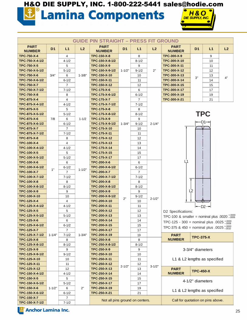
25
D1
L1
L2
D2D2 Specifications:TPC-100 & smaller = nominal plus .0020TPC-125 - 300 = nominal plus .0025TPC-375 & 450 = nominal plus .0025
+.0000–.0006
+.0000–.0008+.0000–.0010
GUIDE PIN STRAIGHT – PRESS FIT GROUNDPART
NUMBER D1 L1 L2 PARTNUMBER D1 L1 L2 PART
NUMBER D1 L1 L2
TPC-750-X-4
3/4"
4
1-3/8"
TPC-150-X-8
1-1/2"
8
2"
TPC-300-X-9
3"
9
4"
TPC-750-X-4-1/2 4-1/2 TPC-150-X-8-1/2 8-1/2 TPC-300-X-10 10TPC-750-X-5 5 TPC-150-X-9 9 TPC-300-X-11 11TPC-750-X-5-1/2 5-1/2 TPC-150-X-9-1/2 9-1/2 TPC-300-X-12 12TPC-750-X-6 6 TPC-150-X-10 10 TPC-300-X-13 13TPC-750-X-6-1/2 6-1/2 TPC-150-X-11 11 TPC-300-X-14 14TPC-750-X-7 7 TPC-150-X-12 12 TPC-300-X-15 15TPC-750-X-7-1/2 7-1/2 TPC-175-X-6
1-3/4"
6
2-1/4"
TPC-300-X-17 17TPC-750-X-8 8 TPC-175-X-6-1/2 6-1/2 TPC-300-X-19 19TPC-875-X-4
7/8
4
1-1/2
TPC-175-X-7 7 TPC-300-X-21 21TPC-875-X-4-1/2 4-1/2 TPC-175-X-7-1/2 7-1/2TPC-875-X-5 5 TPC-175-X-8 8TPC-875-X-5-1/2 5-1/2 TPC-175-X-8-1/2 8-1/2TPC-875-X-6 6 TPC-175-X-9 9TPC-875-X-6-1/2 6-1/2 TPC-175-X-9-1/2 9-1/2TPC-875-X-7 7 TPC-175-X-10 10TPC-875-X-7-1/2 7-1/2 TPC-175-X-11 11TPC-875-X-8 8 TPC-175-X-12 12TPC-100-X-4
1"
4
1-1/2"
TPC-175-X-13 13TPC-100-X-4-1/2 4-1/2 TPC-175-X-14 14TPC-100-X-5 5 TPC-175-X-15 15TPC-100-X-5-1/2 5-1/2 TPC-175-X-17 17TPC-100-X-6 6 TPC-200-X-6
2"
6
2-1/2"
TPC-100-X-6-1/2 6-1/2 TPC-200-X-6-1/2 6-1/2TPC-100-X-7 7 TPC-200-X-7 7TPC-100-X-7-1/2 7-1/2 TPC-200-X-7-1/2 7-1/2TPC-100-X-8 8 TPC-200-X-8 8TPC-100-X-8-1/2 8-1/2 TPC-200-X-8-1/2 8-1/2TPC-100-X-9 9 TPC-200-X-9 9TPC-100-X-10 10 TPC-200-X-9-1/2 9-1/2TPC-125-X-4
1-1/4"
4
1-3/4"
TPC-200-X-10 10TPC-125-X-4-1/2 4-1/2 TPC-200-X-11 11TPC-125-X-5 5 TPC-200-X-12 12TPC-125-X-5-1/2 5-1/2 TPC-200-X-13 13TPC-125-X-6 6 TPC-200-X-14 14TPC-125-X-6-1/2 6-1/2 TPC-200-X-15 15TPC-125-X-7 7 TPC-200-X-17 17TPC-125-X-7-1/2 7-1/2 TPC-200-X-19 15 PART
NUMBER TPC-375-XTPC-125-X-8 8 TPC-250-X-8
2-1/2"
8
3-1/2"
TPC-125-X-8-1/2 8-1/2 TPC-250-X-8-1/2 8-1/23-3/4" diameters
L1 & L2 lengths as specified
TPC-125-X-9 9 TPC-250-X-9 9TPC-125-X-9-1/2 9-1/2 TPC-250-X-10 10TPC-125-X-10 10 TPC-250-X-11 11TPC-125-X-11 11 TPC-250-X-12 12TPC-125-X-12 12 TPC-250-X-13 13 PART
NUMBER TPC-450-XTPC-150-X-4-1/2
1-1/2"
4-1/2
2"
TPC-250-X-14 14TPC-150-X-5 5 TPC-250-X-15 15
4-1/2" diameters
L1 & L2 lengths as specified
TPC-150-X-5-1/2 5-1/2 TPC-250-X-17 17TPC-150-X-6 6 TPC-250-X-19 19TPC-150-X-6-1/2 6-1/2 TPC-250-X-21 21TPC-150-X-7 7
Not all pins ground on centers. Call for quotation on pins above.TPC-150-X-7-1/2 7-1/2
TPC
19
H&O DIE SUPPLY, INC. 1-800-222-5441 [email protected]
26
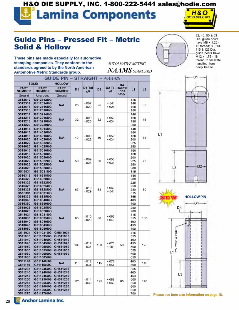
D1
L1
L3 D2
32, 40, 50 & 63Dia. guide postshave M8 x 1.25 -12 thread; 80, 100,115 & 125 Dia.guide posts haveM12 x 1.75 - 18thread to facilitatehandling fromdeep freeze.
These pins are made especially for automotivestamping companies. They conform to thestandards agreed to by the North AmericanAutomotive Metric Standards group.
Guide Pins � Pressed Fit � MetricSolid & Hollow
AUTOMOTIVE METRIC
NAAMS STANDARD
D1
L1
L3
M12-1.75 x 30m
m D
eep
HOLLOW PIN
Please see bore size information on page 18.
D4
GUIDE PIN � STRAIGHT � NAAMSSOLID HOLLOW
D1 D1 Tolg6 D2 D2 Tol
r6
D4Hollow
PinsOnly
L1 L3PARTNUMBER
PARTNUMBER
PARTNUMBER
Ground Unground GroundG512512G512514G512516G512518
G512512UGG512514UGG512516UGG512518UG
N/A 25 -.007-.020 25 +.041
+.028
125140160180
36
G513214G513216G513218G513220
G513214UGG513216UGG513218UGG513220UG
N/A 32 -.009-.025 32 +.050
+.034
140160180200
45
G514014G514016G514018G514020G514022G514025
G514014UGG514016UGG514018UGG514020UGG514022UGG514025UG
N/A 40 -.009-.025 40 +.050
+.034
140160180200225250
56
G515016G515018G515020G515022G515025G515028G515031
G515016UGG515018UGG515020UGG515022UGG515025UGG515028UGG515031UG
N/A 50 -.009-.025 50 +.050
+.034
160180200225250280315
70
G516318G516320G516322G516325G516328G516331G516335G516340G516350
G516318UGG516320UGG516322UGG516325UGG516328UGG516331UGG516335UGG516340UGG516350UG
N/A 63 -.010-.029 63 +.060
+.041
180200225250280315355400500
80
G518025G518028G518031G518035G518040G518045G518050
G518025UGG518028UGG518031UGG518035UGG518040UGG518045UGG518050UG
N/A 80 -.010-.029 80 +.062
+.043
250280315355400450500
100
G511031G511035G511040G511045G511050G511055G511060G511065
G511031UGG511035UGG511040UGG511045UGG511050UGG511055UGG511060UGG511065UG
GH511031GH511035GH511040GH511045GH511050GH511055GH511060
100 -.012-.034 100 +.073
+.051 50
315355400450500550600650
125
G511140G511150
G511140UGG511150UG N/A 115 -.012
-.034 115 +.076+.054
400500 140
G511235G511240G511245G511250G511255G511260G511265G511270
G511235UGG511240UGG511245UGG511250UGG511255UGG511260UGG511265UGG511270UG
GH511235GH511240GH511245GH511250GH511255GH511260GH511265
125 -.014-.039 125 +.088
+.063 65
355400450500550600650700
140
H&O DIE SUPPLY, INC. 1-800-222-5441 [email protected]

27
D1
L1
L2
D1
L1
STRAIGHT GUIDE PINS � METRIC � UNGROUNDPART
NUMBER D1 L1 L2 PARTNUMBER D1 L1 L2
TPB-40MM-X-130
40mm
130
50mm
TPB-50MM-X-260
50mm
260
60mmTPB-40MM-X-140 140 TPB-50MM-X-280 280TPB-40MM-X-150 150 TPB-50MM-X-300 300TPB-40MM-X-160 160 TPB-50MM-X-320 320TPB-40MM-X-170 170 TPB-50MM-X-360 360TPB-40MM-X-180 180 TPB-63MM-X-200
63mm
200
80mm
TPB-40MM-X-190 190 TPB-63MM-X-220 220TPB-40MM-X-200 200 TPB-63MM-x 240 240TPB-40MM-X-220 220 TPB-63MM-X-260 260TPB-40MM-X-240 240 TPB-63MM-X-280 280TPB-40MM-X-260 260 TPB-63MM-X-300 300TPB-40MM-X-280 280 TPB-63MM-X-320 320TPB-40MM-X-300 300 TPB-63MM-X-360 360TPB-40MM-X-320 320 TPB-63MM-X-400 400TPB-40MM-X-360 360 TPB-63MM-X-440 440TPB-50MM-X-150
50mm
150
60mm
TPB-80MM-X-280
80mm
280
100mm
TPB-50MM-X-160 160 TPB-80MM-X-300 300TPB-50MM-X-170 170 TPB-80MM-X-320 320TPB-50MM-X-180 180 TPB-80MM-X-360 360TPB-50MM-X-190 190 TPB-80MM-X-400 400TPB-50MM-X-200 200 TPB-80MM-X-440 440TPB-50MM-X-220 220 TPB-80MM-X-500 500TPB-50MM-X-240 240
GUIDE PINS � STRAIGHT � METRICPART
NUMBER
D1NomPinDia
L1LENGTH
PARTNUMBER
D1NomPinDia
L1LENGTH
TN-19MM-X-120
19mm
120 TN-25MM-X-220
25mm
220TN-19MM-X-130 130 TN-25MM-X-240 240TN-19MM-X-140 140 TN-25MM-X-260 260TN-19MM-X-150 150 TN-25MM-X-280 280TN-19MM-X-160 160 TN-32MM-X-130
32mm
130TN-19MM-X-170 170 TN-32MM-X-140 140TN-19MM-X-180 180 TN-32MM-X-150 150TN-19MM-X-190 190 TN-32MM-X-160 160TN-19MM-X-200 200 TN-32MM-X-170 170TN-25MM-X-120
25mm
120 TN-32MM-X-180 180TN-25MM-X-130 130 TN-32MM-X-190 190TN-25MM-X-140 140 TN-32MM-X-200 200TN-25MM-X-150 150 TN-32MM-X-220 220TN-25MM-X-160 160 TN-32MM-X-240 240TN-25MM-X-170 170 TN-32MM-X-260 260TN-25MM-X-180 180 TN-32MM-X-280 280TN-25MM-X-190 190 TN-32MM-X-300 300TN-25MM-X-200 200
TN -Metric
TPB - Metric
TN pins are designed to be pressed into place. The groundbearing surface is equal top to bottom.
*TPB pins have grind stock on thepress fit end.
D1*
Guide Pins � Pressed Fit � Metric
H&O DIE SUPPLY, INC. 1-800-222-5441 [email protected]

28
Lamina demountable guide pins are tapfit and require toe clamps and screws tohold them in place.
The clamping flange is ground so thatthe flange fits squarely against themounting surface.
Heavy-duty X-40-Clampsare used to secure thepins to the die shoe.
Clamps and screws areincluded.
Guide Pins � Tap Fit
Please see pages 16 & 17 for toe clamp placementinformation and bore size information on page 18.
D1
D2
L1
D3
L5
L3
.187
+.0000�.0005
+.0000�.0002
GUIDE PINS � DEMOUNTABLEPART
NUMBERD1 & D2Nom Pin
Dia
D3+.000�.015
L1±.010
L3±.010
L5(Ref) NO. of
CLAMPSPART
NUMBERD1 & D2Nom Pin
Dia
D3+.000�.015
L1±.010
L3±.010
L5(Ref) NO. of
CLAMPS
DGP0810
1 1.313
3.688
1.188
2.500
3
DGP1032
1-1/4 1.563
9.188
1.188
8.000
3
DGP0811 3.938 2.750 DGP1033 9.438 8.250DGP0812 4.188 3.000 DGP1036 10.188 9.000DGP0813 4.438 3.250 DGP1037 10.438 9.250DGP0814 4.688 3.500 DGP1040 11.188 10.000 DGP0815 4.938 3.750 DGP1041 11.438 10.250 DGP0816 5.188 4.000 DGP1211
1-1/2 1.875
4.188
1.438
2.750
3
DGP0817 5.438 4.250 DGP1212 4.438 3.000DGP0818 5.688 4.500 DGP1213 4.688 3.250DGP0819 5.938 4.750 DGP1214 4.938 3.500DGP0820 6.188 5.000 DGP1215 5.188 3.750DGP0822 6.688 5.500 DGP1216 5.438 4.000DGP0824 7.188 6.000 DGP1217 5.688 4.250DGP0826 7.688 6.500 DGP1218 5.938 4.500DGP0828 8.188 7.000 DGP1219 6.188 4.750DGP0830 8.688 7.500 DGP1220 6.438 5.000DGP0832 9.188 8.000 DGP1221 6.688 5.250DGP1011
1-1/4 1.563
3.938
1.188
2.750
3
DGP1222 6.938 5.500DGP1012 4.188 3.000 DGP1223 7.188 5.750DGP1013 4.438 3.250 DGP1224 7.438 6.000DGP1014 4.688 3.500 DGP1225 7.688 6.250DGP1015 4.938 3.750 DGP1226 7.938 6.500DGP1016 5.188 4.000 DGP1227 8.188 6.750DGP1017 5.438 4.250 DGP1228 8.438 7.000DGP1018 5.688 4.500 DGP1229 8.688 7.250DGP1019 5.938 4.750 DGP1230 8.938 7.500DGP1020 6.188 5.000 DGP1232 9.438 8.000DGP1021 6.438 5.250 DGP1233 9.688 8.250DGP1022 6.688 5.500 DGP1236 10.438 9.000DGP1023 6.938 5.750 DGP1237 10.688 9.250DGP1024 7.188 6.000 DGP1240 11.438 10.000 DGP1025 7.438 6.250 DGP1241 11.688 10.250 DGP1026 7.688 6.500 DGP1414
1-3/4 2.250
5.188
1.688
3.500
4DGP1027 7.938 6.750 DGP1416 5.688 4.000DGP1028 8.188 7.000 DGP1417 5.938 4.250DGP1029 8.438 7.250 DGP1418 6.188 4.500DGP1030 8.688 7.500 DGP1419 6.438 4.750
H&O DIE SUPPLY, INC. 1-800-222-5441 [email protected]

29
Lamina demountable guide pins are tapfit and require toe clamps and screws tohold them in place.
The clamping flange is ground so thatthe flange fits squarely against themounting surface.
Heavy-duty X-40-Clampsare used to secure thepins to the die shoe.
Clamps and screws areincluded.
Guide Pins � Tap Fit
Please see pages 16 & 17 for toe clamp placementinformation and bore size information on page 18.
D1
D2
L1
D3
L5
L3
.187
+.0000�.0005
+.0000�.0002
GUIDE PINS � DEMOUNTABLEPART
NUMBERD1 & D2Nom Pin
Dia
D3+.000�.015
L1±.010
L3±.010
L5(Ref) NO. of
CLAMPSPART
NUMBERD1 & D2Nom Pin
Dia
D3+.000�.015
L1±.010
L3±.010
L5(Ref) NO. of
CLAMPS
DGP1420
1-3/4 2.250
6.688
1.688
5.000
4
DGP2022
2-1/2 3.031
7.438
1.938
5.500
4
DGP1422 7.188 5.500 DGP2024 7.938 6.000DGP1424 7.688 6.000 DGP2026 8.438 6.500DGP1426 8.188 6.500 DGP2028 8.938 7.000DGP1428 8.688 7.000 DGP2030 9.438 7.500DGP1430 9.188 7.500 DGP2032 9.938 8.000DGP1432 9.688 8.000 DGP2034 10.438 8.500DGP1434 10.188 8.500 DGP2036 10.938 9.000DGP1436 10.688 9.000 DGP2038 11.438 9.500DGP1438 11.188 9.500 DGP2040 11.938 10.000DGP1440 11.688 10.000 DGP2042 12.438 10.500DGP1446 13.188 11.500 DGP2048 13.938 12.000DGP1448 13.688 12.000 DGP2054 15.438 13.500DGP1614
2 2.500
5.438
1.938
3.500
4
DGP2056 15.938 14.000DGP1616 5.938 4.000 DGP2064 17.938 16.000DGP1617 6.188 4.250 DGP2066 18.438 16.500DGP1618 6.438 4.500 DGP2418
3 3.500
6.938
2.438
4.500
4
DGP1619 6.688 4.750 DGP2420 7.438 5.000DGP1620 6.938 5.000 DGP2422 7.938 5.500DGP1622 7.438 5.500 DGP2424 8.438 6.000DGP1624 7.938 6.000 DGP2426 8.938 6.500DGP1626 8.438 6.500 DGP2428 9.438 7.000DGP1628 8.938 7.000 DGP2430 9.938 7.500DGP1630 9.438 7.500 DGP2432 10.438 8.000DGP1632 9.938 8.000 DGP2434 10.938 8.500DGP1634 10.438 8.500 DGP2436 11.438 9.000DGP1636 10.938 9.000 DGP2438 11.938 9.500DGP1638 11.438 9.500 DGP2440 12.438 10.000DGP1640 11.938 10.000 DGP2442 12.938 10.500DGP1642 12.438 10.500 DGP2448 14.438 12.000DGP1646 13.438 11.500 DGP2454 15.938 13.500DGP1648 13.938 12.000 DGP2456 16.438 14.000DGP1656 15.938 14.000 DGP2464 18.438 16.000DGP1658 16.438 14.500 DGP2466 18.938 16.500DGP1670 19.438 17.500DGP2018
2-1/2 3.031 6.438
1.938 4.500
4DGP2020 6.938 5.000
H&O DIE SUPPLY, INC. 1-800-222-5441 [email protected]
30
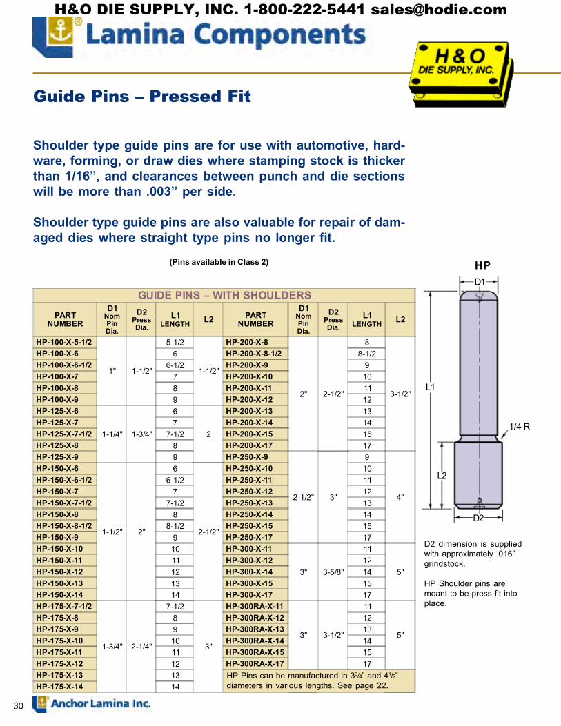
Shoulder type guide pins are for use with automotive, hard-ware, forming, or draw dies where stamping stock is thickerthan 1/16�, and clearances between punch and die sectionswill be more than .003� per side.
Shoulder type guide pins are also valuable for repair of dam-aged dies where straight type pins no longer fit.
(Pins available in Class 2)
D1
L1
D2
L2
1/4 R
HP
D2 dimension is suppliedwith approximately .016�grindstock.
HP Shoulder pins aremeant to be press fit intoplace.
Guide Pins � Pressed Fit
GUIDE PINS � WITH SHOULDERS
PARTNUMBER
D1NomPinDia.
D2PressDia.
L1LENGTH L2 PART
NUMBER
D1NomPinDia.
D2PressDia.
L1LENGTH L2
HP-100-X-5-1/2
1" 1-1/2"
5-1/2
1-1/2"
HP-200-X-8
2" 2-1/2"
8
3-1/2"
HP-100-X-6 6 HP-200-X-8-1/2 8-1/2HP-100-X-6-1/2 6-1/2 HP-200-X-9 9HP-100-X-7 7 HP-200-X-10 10HP-100-X-8 8 HP-200-X-11 11HP-100-X-9 9 HP-200-X-12 12HP-125-X-6
1-1/4" 1-3/4"
6
2
HP-200-X-13 13HP-125-X-7 7 HP-200-X-14 14HP-125-X-7-1/2 7-1/2 HP-200-X-15 15HP-125-X-8 8 HP-200-X-17 17HP-125-X-9 9 HP-250-X-9
2-1/2" 3"
9
4"
HP-150-X-6
1-1/2" 2"
6
2-1/2"
HP-250-X-10 10HP-150-X-6-1/2 6-1/2 HP-250-X-11 11HP-150-X-7 7 HP-250-X-12 12HP-150-X-7-1/2 7-1/2 HP-250-X-13 13HP-150-X-8 8 HP-250-X-14 14HP-150-X-8-1/2 8-1/2 HP-250-X-15 15HP-150-X-9 9 HP-250-X-17 17HP-150-X-10 10 HP-300-X-11
3" 3-5/8"
11
5"HP-150-X-11 11 HP-300-X-12 12HP-150-X-12 12 HP-300-X-14 14HP-150-X-13 13 HP-300-X-15 15HP-150-X-14 14 HP-300-X-17 17HP-175-X-7-1/2
1-3/4" 2-1/4"
7-1/2
3"
HP-300RA-X-11
3" 3-1/2"
11
5"
HP-175-X-8 8 HP-300RA-X-12 12HP-175-X-9 9 HP-300RA-X-13 13HP-175-X-10 10 HP-300RA-X-14 14HP-175-X-11 11 HP-300RA-X-15 15HP-175-X-12 12 HP-300RA-X-17 17HP-175-X-13 13HP-175-X-14 14
HP Pins can be manufactured in 33/4� and 41/2�diameters in various lengths. See page 22.
H&O DIE SUPPLY, INC. 1-800-222-5441 [email protected]
31
See page 17 for clamp placement instructions.
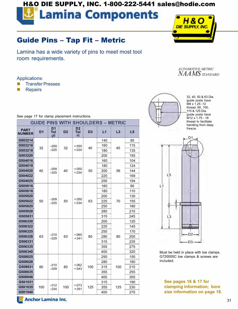
Lamina has a wide variety of pins to meet most toolroom requirements.
Guide Pins � Tap Fit � Metric
Applications:! Transfer Presses! Repairs
See pages 16 & 17 forclamping information; boresize information on page 18.
GUIDE PINS WITH SHOULDERS � METRICPART
NUMBER D1D1Tolg6
D2D2Tolr6
D3 L1 L3 L5
G503214
32 -.009-.025 32 +.050
+.034 40
140
45
95G503216 160 115G503218 180 135G503220 200 155G504016
40 -.009-.025 40 +.050
+.034 50
160
56
104G504018 180 124G504020 200 144G504022 225 169G504025 250 194G505016
50 -.009-.025 50 +.050
+.034 63
160
70
90G505018 180 110G505020 200 130G505022 225 155G505025 250 180G505028 280 210G505031 315 245G506320
63 -.010-.029 63 +.060
+.041 80
200
80
120G506322 225 145G506325 250 170G506328 280 200G506331 315 235G506335 355 275G506340 400 320G508025
80 -.010-.029 80 +.062
+.043 100
250
100
150G508028 280 180G508031 315 215G508035 355 255G508040 400 300G501031
100 -.012-.034 100 +.073
+.051 125315
125190
G501035 355 230G501040 400 275
D1
L5
L1
L3
D2
D3
6
Must be held in place with toe clamps.G720000C toe clamps & screws areincluded.
32, 40, 50 & 63 Dia.guide posts haveM8 x 1.25 -12thread; 80, 100,115 & 125 Dia.guide posts haveM12 x 1.75 - 18thread to facilitatehandling from deepfreeze.
H&O DIE SUPPLY, INC. 1-800-222-5441 [email protected]

32
ASSEMBLIESfor REMOVABLE PIN
PARTNUMBERGround
PARTNUMBERUnground
Nom. PinDia.
GRP-100-ASSY RP-100-ASSY 1.000GRP-125-ASSY RP-125-ASSY 1.250GRP-150-ASSY RP-150-ASSY 1.500GRP-175-ASSY RP-175-ASSY 1.750GRP-200-ASSY RP-200-ASSY 2.000GRP-250-ASSY RP-250-ASSY 2.500GRP-300-ASSY RP-250-ASSY 3.000
Assembly includes 1 bushing liner, 1 End Cap &1 Socket Head Cap Screw
Designed specifically for all dies where it is desirable to re-move pins for ease and simplicity of sharpening die.
Lamina removable pins are generally used with carbide dies,progressive dies, lamination dies, and dies for very thin ma-terials where clearances between punch and die sectionswill be no more than .0007� per side.
D1D2*
L1 2°
BUSHING LINER
D1
SOCKET HEAD CAP SCREW
Guide Pins � RemovablePressed Fit Bushing Liner
Removable pins and assemblies are soldseparately.
BUSHING LINERfor REMOVABLE PIN
PARTNUMBERGround
PARTNUMBERUnground
D1Nom.
Pin Dia.D2*O.D.
L1Length
GNRB-100 NRB-100 1.000 1.50081.5006 1.625
GNRB-125 NRB-125 1.250 1.75081.7506 1.875
GNRB-150 NRB-150 1.500 2.00082.0006 2.125
GNRB-175 NRB-175 1.750 2.25082.2506 2.375
GNRB-200 NRB-200 2.000 2.50082.5006 2.625
GNRB-250 NRB-250 2.500 3.00083.0006 3.625
GNRB-300 NRB-300 3.000 3.50083.5006 4.125
*.016 stock left on this diameter on unground linerfor grinding to fit bored hole in die shoe
END CAP
END CAPfor REMOVABLE PIN
PARTNUMBER
Nom.Pin Dia
D1O.D.
Soc Hd Screw
RC-100- END-CAP 1.000 1.250 5/16-18x1RC-125-END-CAP 1.250 1.500 3/8-16x1RC-150-END-CAP 1.500 1.750 3/8-16x1RC-175-END-CAP 1.750 2.000 3/8-16x1RC-200-END-CAP 2.000 2.250 3/8-16x1RC-250-END-CAP 2.500 2.750 1/2-13x1.5RC-300-END-CAP 3.000 3.250 1/2-13x1.5
GUIDE PIN � REMOVABLEPART
NUMBERD1
Nom. Pin DiaL1
LENGTH L2 TappedHole
RP-100-X-5
1.0000"
+.0001�.0001
5.000
1.500
Pin End5/16-18x3/4
Install End5/16-18
RP-100-X-5-1/2 5.500RP-100-X-6 6.000RP-100-X-6-1/2 6.500RP-100-X-7 7.000RP-100-X-7-1/2 7.500RP-100-X-8 8.000RP-100-X-8-1/2 8.500RP-100-X-9 9.000RP-125-X-5-1/2
1.2500"
+.0001�.0002
5.500
1.750
Pin End5/16-18x7/8
Install End3/8-16
RP-125-X-6 6.000RP-125-X-6-1/2 6.500RP-125-X-7 7.000RP-125-X-7-1/2 7.500RP-125-X-8 8.000RP-125-X-8-1/2 8.500RP-125-X-9 9.000RP-125-X-10 10.000RP-125-X-11 11.000RP-125-X-12 12.000RP-125-X-13 13.000RP-125-X-14 14.000RP-150-X-5-1/2
1.5000"
+.0001�.0002
5.500
2.000
Pin End3/8-16x1
Install End3/8-16
RP-150-X-6 6.000RP-150-X-6-1/2 6.500RP-150-X-7 7.000RP-150-X-7-1/2 7.500RP-150-X-8 8.000RP-150-X-8-1/2 8.500RP-150-X-9 9.000RP-150-X-10 10.000 RP-175-X-7
1.7500"
+.0001�.0002
7.000
2.250
Pin End3/8-16x1
Install End3/8-16
RP-175-X-7-1/2 7.500RP-175-X-8 8.000RP-175-X-8-1/2 8.500RP-175-X-9 9.000RP-175-X-10 10.000 RP-200-X-6
2.0000"
+.0001�.0003
6.000
2.500
Pin End3/8-16x7/8
Install End3/8-16
RP-200-X-7 7.000RP-200-X-7-1/2 7.500RP-200-X-8 8.000RP-200-X-8-1/2 8.500RP-200-X-9 9.000RP-200-X-10 10.000 RP-200-X-11 11.000 RP-200-X-12 12.000 RP-200-X-13 13.000 RP-200-X-14 14.000 RP-250-X-9
2.5000"
+.0001�.0003
9.000
3.500
Pin End1/2-13x1
Pin End1/2-13
RP-250-X-10 10.000 RP-250-X-11 11.000 RP-250-X-12 12.000 RP-250-X-13 13.000 RP-250-X-14 14.000 RP-300-x- 3.0000" Non-Stock; call for quotation
Can be used with Plain Bearing & Keyless Ball-BearingBushing and Retainers.
D1
L1
3/8
L2
2°
REMOVABLE PIN
Tapped HolePin End
Tapped HoleInstall
End
H&O DIE SUPPLY, INC. 1-800-222-5441 [email protected]

33
GiGiGiGiGivvvvve us the oppore us the oppore us the oppore us the oppore us the opportunity to quote ytunity to quote ytunity to quote ytunity to quote ytunity to quote your specialsour specialsour specialsour specialsour specials.....! Quick turnaround time on round & flat products (2 weeks on many)! You get exact product you need! Opportunity for innovation! Call or e-mail for quote template
Specials!
Please send yourprints [email protected]!
H&O DIE SUPPLY, INC. 1-800-222-5441 [email protected]
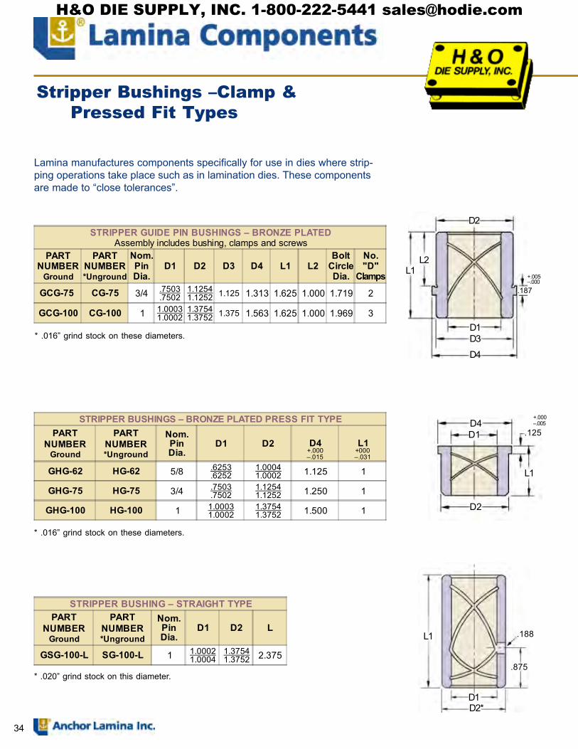
34
L1 .188
D1D2*
.875
D1
L1
D4
D2
.125
D1
D2
L1L2
.187
D4
Lamina manufactures components specifically for use in dies where strip-ping operations take place such as in lamination dies. These componentsare made to �close tolerances�.
+.005�.000
STRIPPER GUIDE PIN BUSHINGS � BRONZE PLATEDAssembly includes bushing, clamps and screws
PARTNUMBER
Ground
PARTNUMBER*Unground
Nom.PinDia.
D1 D2 D3 D4 L1 L2Bolt
CircleDia.
No."D"
Clamps
GCG-75 CG-75 3/4 .7503.7502
1.12541.1252 1.125 1.313 1.625 1.000 1.719 2
GCG-100 CG-100 1 1.00031.0002
1.37541.3752 1.375 1.563 1.625 1.000 1.969 3
STRIPPER BUSHINGS � BRONZE PLATED PRESS FIT TYPEPART
NUMBERGround
PARTNUMBER*Unground
Nom.PinDia.
D1 D2 D4+.000�.015
L1+000�.031
GHG-62 HG-62 5/8 .6253.6252
1.00041.0002 1.125 1
GHG-75 HG-75 3/4 .7503.7502
1.12541.1252 1.250 1
GHG-100 HG-100 1 1.00031.0002
1.37541.3752 1.500 1
STRIPPER BUSHING � STRAIGHT TYPEPART
NUMBERGround
PARTNUMBER*Unground
Nom.PinDia.
D1 D2 L
GSG-100-L SG-100-L 1 1.00021.0004
1.37541.3752 2.375
* .016� grind stock on these diameters.
* .016� grind stock on these diameters.
* .020� grind stock on this diameter.
Stripper Bushings �Clamp &Pressed Fit Types
D3
+.000�.005
H&O DIE SUPPLY, INC. 1-800-222-5441 [email protected]

35
1/4� G Screw
R1
D3
D1
D1
L2
L1
1�
L3
�CG�Type
DIESHOE
STRIPPERPLATE
DIERETAINER
DIESHOE
�HG�Type
STRIPPER PIN & BUSHING APPLICATION
STRIPPER PIN � FLANGE STYLEPART
NUMBERNom.PinDia.
D1 D2*±.003
D3 L1 L2 L3 R1 "G"Screws
F-8890 7/8 .8750.8748 .900 2.00 9.00 3.750 3.00 .719 Flat Head
F-1080 1 1.00000.9998 1.025 2.00 8.00 3.500 1.50 .750 Soc. Head
F-1085 1 1.00000.9998 1.025 2.00 8.50 3.500 1.50 .750 Soc. Head
F-1090 1 1.00000.9998 1.025 2.00 9.00 3.500 1.50 .750 Soc. Head
F-1290 1-1/4 1.25001.2498 1.275 2.25 9.00 3.500 1.50 .875 Soc. Head
*The D2 diameter is unground. Suggested finsh bore size to be .005 over nominal pin diameter.
D2
.250
D1
D1
L2
L1 L3 D2*
3/4
.406
Stripper Pins � Pressed Fit &Flange Types
STRIPPER PINS � PRESS FIT TYPEPART
NUMBERNom.PinDia.
D1 D2* L1 L2 L3
SGP-62-X-4 5/8 .6250.6248 .640 4.00 2.25 .750
SGP-62-X-5 5/8 .6250.6248 .640 5.00 2.25 .750
SGP-75-X-5 3/4 .7500.7498 .765 5.00 2.25 .875
SGP-75-X-6-1/2 3/4 .7500.7498 .765 6.50 2.75 .875
SGP-100-X-6-1/2 1 1.0000 0.9998 1.015 6.50 2.75 1.000
SGP-100-X-7-1/2 1 1.0000 0.9998 1.015 7.50 2.75 1.000
*The D2 diameter is unground. Suggested finish grind size for D2 dimension to be .001 over nominal pin diameter.
H&O DIE SUPPLY, INC. 1-800-222-5441 [email protected]

36
PURPOSEAvailable as ReplacementPart No. DL75 Die LifeRetaining Washer. 6 perpackage. Includes flathead socket screw 5/16-18x1.Note: In blanking diesections order optionalDie Life �DL� RetainingWashers: Counterborehole must be deeper.
W Dia.
U
R Dia.
TS
VRadius
dCounterbore
b
c REAM
a
gCounterborein strippingplatef
.187 h ij
ATravelp
.156
n
B
kC
D
E
m
5/16-18 x 5/8Socket ButtonHead Screw
MODEL 75HARDENED, GROUND AND VENTED
Rockwell: RC 52-56Case Hardened .015 � .030 Deep
Packaged complete with spring, screw and retaining washer
When ordering please specify:1. Quantity2. Catalog Number
Lifters with travel greater than 1.75 are available. Priced on applica-tion. (Furnished without spring.)
HEAVY DUTY STOCK LIFTERS
LIFTER SPECIFICATIONSA � Operating Travel D � Pocket Depth for SpringB � Lifter Body Length E � Spring Free LengthC � Pocket Depth for Lifter Body F � Slot Length
Replacement Washer � #75WASHERReplacement Screw � #75SCREWDie Life Package � #DL75 (6 per package)
PARTNUMBER
ATRAVEL
BLIFTER
LENGTH
CLIFTER
DSPRINGPOCKET
ESPRINGFREE
LENGTH
FSLOT
LENGTH
REPLACE-MENT DIESPRING
Lbs@1/10"SPRING
DEFLECT-ION
75-50 0.50 2.312 2.50 2.938 2.50 1.000 M-113 4.575-75 0.75 2.562 2.75 3.938 3.50 1.250 M-115 3.075-1-0 1.00 2.812 3.00 4.938 4.50 1.500 M-115A 2.5
75-1-25 1.25 3.062 3.25 5.938 5.50 1.750 M-115B 2.175-1-50 1.50 3.312 3.50 6.938 6.50 2.000 M-115C 1.475-1-75 1.75 3.562 3.75 7.938 7.50 2.250 M-115D 1.2
VALUES CONSTANT FOR ALL 75 LIFTERSa .578 Dimension between CL of Lifter Pocket to CL of Socket Screwb .203 Slot Depth ±.005c .750 Pocket Diameter for Lifter Body +.001 �.000d .688 Counter Bore Diameter for Lifter Washerf .25 Counter Bore Depth in Stripper Plate, minus half of stock thicknessg .781 Counter Bore Diameter in Stripper Plateh .7495 Lifter Body Diameter +.0000 �.0015i .125 Slot Height (for Stock) ±.005j .187 Dimension from Top of Slot to Top of Body ±.005k 1.000 �Length of Spring Pocket in Lifter Bodym .50 Spring Pocket Diametern 1.125 Dimension from Bottom of Washer (Slot) to Bottom of Bodyp .375 Counter Bore Depth for Washer & Socket Screw
MODEL 75 Stock Lifter O.D. .7495�(For Stock up to .094� thick)
DIE LIFEREPLACEMENT RETAINING WASHER & SCREW KIT
PARTNUMBER R S T U V W
DL75 .656 .490 .280 .585 .390 .330
F
H&O DIE SUPPLY, INC. 1-800-222-5441 [email protected]
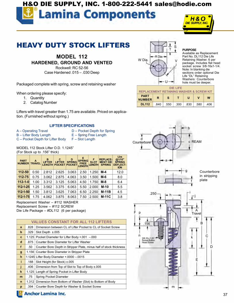
37
PURPOSEAvailable as ReplacementPart No. DL112 Die LifeRetaining Washer. 6 perpackage. Includes flat headsocket screw 3/8-16x1-1/4.Note: In blanking diesections order optional DieLife �DL� RetainingWashers: Counterborehole must be deeper.
HEAVY DUTY STOCK LIFTERSMODEL 112
HARDENED, GROUND AND VENTEDRockwell: RC 52-56
Case Hardened .015 � .030 Deep
DIE LIFEREPLACEMENT RETAINING WASHER & SCREW KIT
PARTNUMBER R S T U V W
DL112 .840 .550 .300 .830 .580 .406
dCounterbore
b
c REAM
a
g
f
h.250 j
Counterborein strippingplate
ATravel
k
B
C
D
n
.156
p
3/8-16 x 1.00Socket ButtonHead Screw
m
Packaged complete with spring, screw and retaining washer
When ordering please specify:1. Quantity2. Catalog Number
Lifters with travel greater than 1.75 are available. Priced on applica-tion. (Furnished without spring.)
LIFTER SPECIFICATIONSA � Operating Travel D � Pocket Depth for SpringB � Lifter Body Length E � Spring Free LengthC � Pocket Depth for Lifter Body F � Slot Length
MODEL 112 Stock Lifter O.D. 1.1245�(For Stock up to .156� thick)
PARTNUMBER
ATRAVEL
BLIFTER
LENGTH
CLIFTER
DSPRINGPOCKET
ESPRINGFREE
LENGTH
FSLOT
LENGTH
REPLACE-MENT DIESPRING
Lbs@1/10"SPRING
DEFLECT-ION
112-50 0.50 2.812 2.625 3.063 2.50 1.250 M-4 12.0112-75 0.75 3.062 2.875 4.063 3.50 1.500 M-6 8.0112-1-0 1.00 3.312 3.125 5.063 4.50 1.750 M-8 6.4112-1-25 1.25 3.562 3.375 6.063 5.50 2.000 M-10 5.5112-1-50 1.50 3.812 3.625 7.063 6.50 2.250 M-11B 4.5112-1-75 1.75 4.062 3.875 8.063 7.50 2.500 M-11C 3.8
F
E
VALUES CONSTANT FOR ALL 112 LIFTERSa .828 Dimension between CL of Lifter Pocket to CL of Socket Screwb .329 Slot Depth ±.005c 1.125 Pocket Diameter for Lifter Body +.001 �.000d .875 Counter Bore Diameter for Lifter Washerf .50 Counter Bore Depth in Stripper Plate, minus half of stock thicknessg 1.156 Counter Bore Diameter in Stripper Plateh 1.1245 Lifter Body Diameter +.0000 �.0015i .188 Slot Height (for Stock) ±.005j .406 Dimension from Top of Slot to Top of Body ±.005k 1.125 Length of Spring Pocket in Lifter Bodym .75 Spring Pocket Diametern 1.312 Dimension from Bottom of Washer (Slot) to Bottom of Bodyp .394 Counter Bore Depth for Washer & Socket Screw
Replacement Washer � #112 WASHERReplacement Screw � #112 SCREWDie Life Package � #DL112 (6 per package)
W Dia.
U
R Dia.
TS
i
V
H&O DIE SUPPLY, INC. 1-800-222-5441 [email protected]

38
5/16 -18 x .625 tap
Rail &Screw NotFurnished
.187
Optional: TackWeld at Assembly
B.156
G
5/16-18 x 5/8Socket ButtonHead Screw
ATravel
a
dCounter bore
c REAM
p
nk
F
EC & D
h
PARTNUMBER
ATRAVEL
BLIFTER
LENGTH
C &DLIFTER
POCKETG
ESPRINGFREE
LENGTH
FSLOT
LENGTH
REPLACE-MENT DIESPRING
Lbs @1/10"SPRING
DEFLECTION
T-750-50 0.50 2.312 2.500 1.187 2.50 1.000 M-113 4.5T-750-75 0.75 2.562 3.500 1.437 3.50 1.250 M-115 3.0T-750-1-0 1.00 2.812 4.500 1.687 4.50 1.500 M-115A 2.5T-750-1-25 1.25 3.062 5.500 1.937 5.50 1.750 M-115B 2.1T-750-1-50 1.50 3.312 6.500 2.187 6.50 2.000 M-115C 1.4T-750-1-75 1.75 3.562 7.500 2.437 7.50 2.250 M-115D 1.2
MODEL T-750HARDENED, GROUND AND VENTED
Rockwell: RC 52-56Case Hardened .015 � .030 Deep
HEAVY DUTY RAIL STOCK LIFTER PINS
Package complete with spring, screw and retaining washer.
When ordering please specify:1. Quantity2. Catalog Number
LIFTER SPECIFICATIONS
A � Operating Travel D � Pocket Depth for SpringB � Lifter Body Length E � Spring Free LengthC � Pocket Depth for F � Slot length
Lifter Body G � Top of Die to Top of Lifter Body
Rail Stock Lifter O.D. .7495� +.0000 �.0015
Replacement Washer Part Number � 75WASHERReplacement Screw Part Number � 75SCREW
VALUES CONSTANT FOR ALL 75 -T LIFTERSa .578 Dimension between CL of Lifter Pocket to CL of Socket Screwc .750 Pocket Diameter for Lifter Body +.001 �.000d .688 Counter Bore Diameter for Lifter Washerh .7495 Lifter Body Diameter +.0000 �.0015i .125 Slot Height (for Stock) ±.005j .187 Dimension from Top of Slot to Top of Body ±.005k 1.000 �Length of Spring Pocket in Lifter Bodyn 1.125 Dimension from Bottom of Washer (Slot) to Bottom of Bodyp .375 Counter Bore Depth for Washer & Socket Screw
H&O DIE SUPPLY, INC. 1-800-222-5441 [email protected]

39
3/8-16 x 1� tap
dCounter bore
c Ream
a
Rail &Screw NotFurnished
.250
Optional TackWeld at Assembly
ATravelG
n
.156
p
B
C & D
k
3/8-16 x 1.00Socket ButtonHead Screw
F
E
h
HEAVY DUTY RAIL STOCK LIFTER PINS
MODEL 112THARDENED, GROUND AND VENTED
Rockwell: RC 52-56Case Hardened .015 � .030 Deep
Package complete with spring, screw and retaining washer.
When ordering please specify:1. Quantity2. Catalog Number
A � Operating Travel D � Pocket Depth for SpringB � Lifter Body Length E � Spring Free LengthC � Pocket Depth for F � Slot length
Lifter Body G � Top of Die to Top of Lifter Body
LIFTER SPECIFICATIONS
Rail Stock Lifter O.D. 1.1245� +.0000 �.0015
PARTNUMBER
ATRAVEL
BLIFTER
LENGTH
C &DLIFTER
POCKETG
ESPRING
F.L.
FSLOT
LENGTH
REPLACE-MENT DIESPRING
Lbs @1/10"SPRING
DEFLECTION
112T-50 0.50 2.812 2.562 1.500 2.50 1.250 M-4 12.0112T-75 0.75 3.062 3.562 1.750 3.50 1.500 M-6 8.0112T-1-00 1.00 3.312 4.562 2.000 4.50 1.750 M-8 6.4112T-1-25 1.25 3.562 5.562 2.250 5.50 2.000 M-10 5.5112T-1-50 1.50 3.812 6.562 2.500 6.50 2.250 M-11B 4.5112T-1-75 1.75 4.062 7.562 2.750 7.50 2.500 M-11C 3.8
Replacement Washer Part Number � 112WASHERReplacement Screw Part Number � 112SCREW
VALUES CONSTANT FOR ALL 112-T LIFTERSa .828 Dimension between CL of Lifter Pocket to CL of Socket Screwc 1.125 Pocket Diameter for Lifter Body +.001 �.000d .875 Counter Bore Diameter for Lifter Washerh 1.1245 Lifter Body Diameter +.0000 �.0015i .188 Slot Height (for Stock) ±.005j .406 Dimension from Top of Slot to Top of Body ±.005k 1.125 Length of Spring Pocket in Lifter Bodyn 1.312 Dimension from Bottom of Washer (Slot) to Bottom of Bodyp .394 Counter Bore Depth for Washer & Socket Screw
H&O DIE SUPPLY, INC. 1-800-222-5441 [email protected]

40
ML-
50-6
3
ML-
50-4
4
ML-
50-2
5
ML-
38-2
5
ML-
38-4
4
ML-
38-6
3OPTIONAL DIE LEVEL
FULL SCALE TEMPLATE
.56Dia.
.4990Dia.
.17
.12.16 .16
A Travel.10
B
.54Opt.
.21
.16
1/4-20x.5Screw
.62
.13
E DMin.
1/8 InitialSpringComp.4 to 1Ratio
.375 Ream .375 Dia.
.130±.010�.000.38R10-24 Dog
Pt. Screw& Lock Nut
.130 Widthof Slot
Air Relief .355
.130±.010�.000
.475
.500 Ream .500 Dia.Air Relief
.5R
.160 Width of slot1/4-20 Dog Pt. Screw & Lock Nut
Mini-LiftersTop or Side Mounted
3/8� and 1/2� diameters each to 3 different lengths. Hardened, ground and vented.Accurately machined from solid bar steel and packaged complete with spring,
socket head cap screw, dog point screw and retaining washer.Immediately available from Inventory.
.44Dia.
.17
B .07
.09
A Travel
.56Opt.
.3740Dia.
.16 .155
10-24x.38Screw
.62.13
.125
E DMin.
ML-38ML-50
+.0000�.0005
Dog Point Washer
PARTNUMBER
ATRAVEL
BLENGTH
CBORE
LENGTHD
MIN
ESPRINGFREE
LENGTH
FSLOT
LENGTH
REPLACE-MENT DIESPRING
Lbs @1/10"
SPRINGDEFLEC-
TION
ML-50-25 .25 1.28 2.13 2.30 1.50 .990 M-111 6.8ML-50-44 .44 1.47 2.63 2.80 2.00 1.180 M-112 5.5ML-50-63 .63 1.66 3.13 3.30 2.50 1.370 M-113 4.5
PARTNUMBER
ATRAVEL
BLENGTH
CBORE
LENGTHD
MIN
ESPRINGFREE
LENGTH
FSLOT
LENGTH
REPLACE-MENT DIESPRING
Lbs @1/10"
SPRINGDEFLEC-
TION
ML-38-25 .25 1.25 2.13 2.30 1.50 .970 M-101 4.0ML-38-44 .44 1.44 2.63 2.80 2.00 1.160 M-102 2.8ML-38-63 .63 1.63 3.13 3.30 2.50 1.350 M-103 2.4
C
F
+.0000�.0005
F
C
Note: Can be guided bydog point washer or dogpoint screw
H&O DIE SUPPLY, INC. 1-800-222-5441 [email protected]

41
STOCKLIFTER REPLACEMENT PARTSPART
NUMBERREPLACEMENT
SPRINGREPLACEMENT
WASHERSREPLACEMENT
SCREWDIE LIFE KIT
6 SETS75-50T-75-50 M-113 75WASHER 75SCREW DL75
75-75T-75-75 M-115 75WASHER 75SCREW DL75
75-1-0T-75-1-0 M-115A 75WASHER 75SCREW DL75
75-1-25T-75-1-25 M-115B 75WASHER 75SCREW DL75
75-1-50T-75-1-50 M-115C 75WASHER 75SCREW DL75
75-1-75T-75-1-75 M-115D 75WASHER 75SCREW DL75
112-50112T-50 M-4 112WASHER 112SCREW DL112
112-75112T-75 M-6 112WASHER 112SCREW DL112
112-1-0112T-1-00 M-8 112WASHER 112SCREW DL112
112-1-25112T-1-25 M-10 112WASHER 112SCREW DL112
112-1-50112T-1-50 M-11B 112WASHER 112SCREW DL112
112-1-75112T-1-75 M-11C 112WASHER 112SCREW DL112
ML-38-25ML-38-44ML-38-63
M-101M-102M-103
38WASHER N/A N/A
ML-50-25ML-50-44ML-50-63
M-111M-112M-113
50WASHER N/A N/A
Design in (and build in) stock lifters just as easily as you do diesprings and pins. Standard notched lifters are made in twosizes to handle stock up to .156� thick. Side center-rail liftersthat easily accept your special rails are also offered.
These lifters all install from the top only. Easier to do and theycan be replaced without taking the die from the press. All theyneed are two drilled holes, one tapped. Drop the spring andlifter in the larger one and secure them with the retaining screwin the tapped hole.
Go to standard lifters for consistent quality � they�re all solid barsteel, hardened, ground and vented. You can�t build themyourself for less.
H&O DIE SUPPLY, INC. 1-800-222-5441 [email protected]

42
SPOOL TYPEPAD RETAINER-LOCKING
PARTNUMBER D1
D2+.000-.010
L2 L3 S1 S2 RADIUSLOAD
RATINGLBS
PRL100 1.00 .75 1.00 .38 5/8-18 5/16-18 .03 1,500PRL125 1.25 1.00 1.12 .50 3/4-16 3/8-16 .03 3,000PRL162 1.62 1.25 1.12 .50 7/8-14 1/2-13 .06 5,000PRL187 1.87 1.50 1.25 .50 1-1/8-12 5/8-11 .06 7,500PRL200 2.00 1.62 1.38 .50 1-1/4-12 3/4-10 .06 10,000
L3 L1�S1� Socket Set Screw �S2� Socket Head Cap Screw
D1
L2 L4 Knurled
D2
Radius
Assembly includes:Retainer BodySocket Head Cap ScrewSocket Set Screw
BLACK OXIDE TREATMENT
SPOOL TYPE PAD RETAINERS � LOCKING with KNURLED SURFACE
L1±.005
Series PRL 100 Series PRL 125 Series PRL 162 Series PRL 187 Series PRL 200PART
NUMBER L4 PARTNUMBER L4 PART
NUMBER L4 PARTNUMBER L4 PART
NUMBER L4
1.00 PRL100100 1.00 PRL125100 1.25 PRL162100 1.501.25 PRL100125 1.25 PRL125125 1.50 PRL162125 1.75 PRL187125 1.751.50 PRL100150 1.50 PRL125150 1.75 PRL162150 2.00 PRL187150 2.00 PRL200150 2.251.75 PRL100175 1.75 PRL125175 2.00 PRL162175 2.25 PRL187175 2.25 PRL200175 2.502.00 PRL100200 2.00 PRL125200 2.25 PRL162200 2.50 PRL187200 2.50 PRL200200 2.752.25 PRL100225 2.25 PRL125225 2.50 PRL162225 2.75 PRL187225 2.75 PRL200225 3.002.50 PRL100250 2.50 PRL125250 2.75 PRL162250 3.00 PRL187250 3.00 PRL200250 3.252.75 PRL100275 2.75 PRL125275 3.00 PRL162275 3.25 PRL187275 3.25 PRL200275 3.503.00 PRL100300 3.00 PRL125300 3.25 PRL162300 3.50 PRL187300 3.50 PRL200300 3.753.25 PRL100325 3.25 PRL125325 3.50 PRL162325 3.75 PRL187325 4.00 PRL200325 4.003.50 PRL100350 3.50 PRL125350 4.00 PRL162350 4.00 PRL187350 4.00 PRL200350 4.003.75 PRL125375 4.00 PRL162375 4.50 PRL187375 4.50 PRL200375 4.504.00 PRL125400 4.50 PRL162400 4.50 PRL187400 4.50 PRL200400 4.504.50 PRL125450 5.00 PRL162450 5.00 PRL187450 5.00 PRL200450 5.005.00 PRL125500 5.50 PRL162500 5.50 PRL187500 5.50 PRL200500 5.505.50 PRL125550 6.00 PRL162550 6.00 PRL187550 6.00 PRL200550 6.006.00 PRL125600 6.00 PRL162600 6.50 PRL187600 6.50 PRL200600 6.50
H&O DIE SUPPLY, INC. 1-800-222-5441 [email protected]

43
BLACK OXIDE TREATMENT
Assembly includes:Retainer BodySocket Head Cap ScrewSocket Set Screw
SPOOL TYPEPAD RETAINER-LOCKINGwith FLATS
SPOOL TYPE PAD RETAINERS � LOCKING with FLATS
L1±.005
Series PRLF 100 Series PRLF 125 Series PRLF 162 Series PRLF 187 Series PRLF 200PART
NUMBER L4 PARTNUMBER L4 PART
NUMBER L4 PARTNUMBER L4 PART
NUMBER L4
1.00 PRLF100100 1.00 PRLF125100 1.25 PRLF162100 1.501.25 PRLF100125 1.25 PRLF125125 1.50 PRLF162125 1.75 PRLF187125 1.751.50 PRLF100150 1.50 PRLF125150 1.75 PRLF162150 2.00 PRLF187150 2.00 PRLF200150 2.251.75 PRLF100175 1.75 PRLF125175 2.00 PRLF162175 2.25 PRLF187175 2.25 PRLF200175 2.502.00 PRLF100200 2.00 PRLF125200 2.25 PRLF162200 2.50 PRLF187200 2.50 PRLF200200 2.752.25 PRLF100225 2.25 PRLF125225 2.50 PRLF162225 2.75 PRLF187225 2.75 PRLF200225 3.002.50 PRLF100250 2.50 PRLF125250 2.75 PRLF162250 3.00 PRLF187250 3.00 PRLF200250 3.252.75 PRLF100275 2.75 PRLF125275 3.00 PRLF162275 3.25 PRLF187275 3.25 PRLF200275 3.503.00 PRLF100300 3.00 PRLF125300 3.25 PRLF162300 3.50 PRLF187300 3.50 PRLF200300 3.753.25 PRLF100325 3.25 PRLF125325 3.50 PRLF162325 3.75 PRLF187325 4.00 PRLF200325 4.003.50 PRLF100350 3.50 PRLF125350 4.00 PRLF162350 4.00 PRLF187350 4.00 PRLF200350 4.003.75 PRLF125375 4.00 PRLF162375 4.50 PRLF187375 4.50 PRLF200375 4.504.00 PRLF125400 4.50 PRLF162400 4.50 PRLF187400 4.50 PRLF200400 4.504.50 PRLF125450 5.00 PRLF162450 5.00 PRLF187450 5.00 PRLF200450 5.005.00 PRLF125500 5.50 PRLF162500 5.50 PRLF187500 5.50 PRLF200500 5.505.50 PRLF125550 6.00 PRLF162550 6.00 PRLF187550 6.00 PRLF200550 6.006.00 PRLF125600 6.00 PRLF162600 6.50 PRLF187600 6.50 PRLF200600 6.50
D1
L3 L1Radius
�S2� Socket HeadCap Screw
D2
L2 L4 Knurled
�S1� Socket Set Screw
PARTNUMBER D1
D2+.000-.010
L2 L3 S1 S2 F RADIUSLOAD
RATINGLBS
PRLF100 1.00 .75 1.00 .38 5/8-18 5/16-18 .625 .03 1,500PRLF125 1.25 1.00 1.12 .50 3/4-16 3/8-16 .875 .03 3,000PRLF162 1.62 1.25 1.12 .50 7/8-14 1/2-13 1.125 .06 5,000PRLF187 1.87 1.50 1.25 .50 1-1/8-12 5/8-11 1.250 .06 7,500PRLF200 2.00 1.62 1.38 .50 1-1/4-12 3/4-10 1.375 .06 10,000
FAcross Flats
.38
H&O DIE SUPPLY, INC. 1-800-222-5441 [email protected]

44
SPOOL TYPEPAD RETAINER-REVERSED
Includes:Body Only, Customer is tosupply Socket Head Screwand optional Locking Pin.
BLACK OXIDE TREATMENT
SPOOL TYPE PAD RETAINERS � REVERSED STANDARDSeries PRR 100 Series PRR 125 Series PRR 162 Series PRR 187 Series PRR 200
L1±.005
PARTNUMBER
PARTNUMBER
PARTNUMBER
PARTNUMBER
PARTNUMBER
1.00 PRR100100 PRR1251001.25 PRR100125 PRR125125 PRR1621251.50 PRR100150 PRR125150 PRR162150 PRR1871501.75 PRR100175 PRR125175 PRR162175 PRR187175 PRR2001752.00 PRR100200 PRR125200 PRR162200 PRR187200 PRR2002002.25 PRR100225 PRR125225 PRR162225 PRR187225 PRR2002252.50 PRR100250 PRR125250 PRR162250 PRR187250 PRR2002502.75 PRR100275 PRR125275 PRR162275 PRR187275 PRR2002753.00 PRR100300 PRR125300 PRR162300 PRR187300 PRR2003003.25 PRR100325 PRR125325 PRR162325 PRR187325 PRR2003253.50 PRR100350 PRR125350 PRR162350 PRR187350 PRR2003503.75 PRR100375 PRR125375 PRR162375 PRR187375 PRR2003754.00 PRR100400 PRR125400 PRR162400 PRR187400 PRR2004004.50 PRR100450 PRR125450 PRR162450 PRR187450 PRR2004505.00 PRR100500 PRR125500 PRR162500 PRR187500 PRR2005005.50 PRR100550 PRR125550 PRR162550 PRR187550 PRR2005506.00 PRR100600 PRR125600 PRR162600 PRR187600 PRR200600
D1
L3 L1
.25.38
L2D2
Knurled
T1 Tapped Hole*(2) x Screw Diameter (Min)
Radius G*
PARTNUMBER D1
D2+.000-.010
T1 L3 RADIUS L2 GLOAD
RATINGLBS
PRR100 1.00 .75 5/16-18 .38 .03 .18 .625 1,500PRR125 1.25 1.00 3/8-16 .50 .03 .25 .750 3,000PRR162 1.62 1.25 1/2-13 .50 .06 .25 1.000 5,000PRR187 1.87 1.50 5/8-11 .50 .06 .25 1.250 7,500PRR200 2.00 1.62 3/4-10 .50 .06 .25 1.500 10,000
H&O DIE SUPPLY, INC. 1-800-222-5441 [email protected]

45
SPOOL TYPE PAD RETAINERS � REVERSED with FLATSSeries PRR 100 Series PRR 125 Series PRR 162 Series PRR 187 Series PRR 200
L1±.005
PARTNUMBER
PARTNUMBER
PARTNUMBER
PARTNUMBER
PARTNUMBER
1.00 PRRF100100 PRRF1251001.25 PRRF100125 PRRF125125 PRRF1621251.50 PRRF100150 PRRF125150 PRRF162150 PRRF1871501.75 PRRF100175 PRRF125175 PRRF162175 PRRF187175 PRRF2001752.00 PRRF100200 PRRF125200 PRRF162200 PRRF187200 PRRF2002002.25 PRRF100225 PRRF125225 PRRF162225 PRRF187225 PRRF2002252.50 PRRF100250 PRRF125250 PRRF162250 PRRF187250 PRRF2002502.75 PRRF100275 PRRF125275 PRRF162275 PRRF187275 PRRF2002753.00 PRRF100300 PRRF125300 PRRF162300 PRRF187300 PRRF2003003.25 PRRF100325 PRRF125325 PRRF162325 PRRF187325 PRRF2003253.50 PRRF100350 PRRF125350 PRRF162350 PRRF187350 PRRF2003503.75 PRRF100375 PRRF125375 PRRF162375 PRRF187375 PRRF2003754.00 PRRF100400 PRRF125400 PRRF162400 PRRF187400 PRRF2004004.50 PRRF100450 PRRF125450 PRRF162450 PRRF187450 PRRF2004505.00 PRRF100500 PRRF125500 PRRF162500 PRRF187500 PRRF2005005.50 PRRF100550 PRRF125550 PRRF162550 PRRF187550 PRRF2005506.00 PRRF100600 PRRF125600 PRRF162600 PRRF187600 PRRF200600
Includes:Body Only, Customer is tosupply Socket Head Screw.
SPOOL TYPEPAD RETAINER-REVERSEDwith FLATS
BLACK OXIDE TREATMENT
D1
L3 L1
G*
.38
D2
Knurled
*(2) x Screw Diameter (Min)
T1 Tapped Hole
FAcross Flats
Radius
PARTNUMBER D1
D2+.000-.010
T1 L3 RADIUS F GLOAD
RATINGLBS
PRRF100 1.00 .75 5/16-18 .38 .03 .625 .625 1,500PRRF125 1.25 1.00 3/8-16 .50 .03 .875 .750 3,000PRRF162 1.62 1.25 1/2-13 .50 .06 1.125 1.000 5,000PRRF187 1.87 1.50 5/8-11 .50 .06 1.250 1.250 7,500PRRF200 2.00 1.62 3/4-10 .50 .06 1.375 1.500 10,000
H&O DIE SUPPLY, INC. 1-800-222-5441 [email protected]

46
SPOOL TYPEPAD RETAINERS - METRIC
Assembly includes:Retainer BodySocket Head Cap ScrewSocket Set Screw
ØD1
S1 Socket Set ScrewL1 ±0.13
S2 Socket Head Cap ScrewR1.5
D2
L2 L4 Knurl
+0.00-0.02
L3
SPOOL TYPE PAD RETAINERS � LOCKING METRIC
L1±0.13
Series R3250 SERIES R3270PART
NUMBER L4 PARTNUMBER L4
30 R325030 4540 R325040 55 R327040 5545 R325045 60 R327045 6050 R325050 65 R327050 6560 R325060 75 R327060 7565 R325065 80 R327065 8070 R325070 90 R327070 9075 R325075 90 R327075 9090 R325090 110 R327090 110100 R325010 120 R327010 120115 R325011 130 R327011 130130 R325013 150 R327013 150140 R325014 160 R327014 160160 R325016 180 R327016 180
PARTNUMBER D1 D2 L2 L3 S1 S2 LOAD
RATING
R3250 50 40 35 15 M27 x 2 M16 x 2.0 192 kNR3270 70 60 40 15 M36 x 3 M20 x 2.5 299 kN
H&O DIE SUPPLY, INC. 1-800-222-5441 [email protected]

47
PRY BARSHIGH CARBON FORGED STEEL TOOLS
Rugged in construction and specially designed for easy handling, long life,and demanding professional use.
Bronze tip and heel preventdamage to die and moldsurfaces.
20�
36�
PRY-BAR#36
PRY-BAR#20
H&O DIE SUPPLY, INC. 1-800-222-5441 [email protected]