© s. ramesh / krithi ramamritham / kavi arya 1 it-606 embedded systems (software) s. ramesh krithi...
TRANSCRIPT
1© S. Ramesh / Krithi Ramamritham / Kavi Arya
IT-606Embedded Systems
(Software)
S. RameshKrithi Ramamritham
Kavi Arya
KReSIT/ IIT Bombay

2© S. Ramesh / Krithi Ramamritham / Kavi Arya
Models and Tools for Embedded Systems
S. Ramesh

3© S. Ramesh / Krithi Ramamritham / Kavi Arya
Organization1. Model-based Development of Emb. Sys.2. Review of models of concurrency in
programming languages3. Synchronous Model of concurrency4. Introduction to Esterel5. Advanced Features of Esterel6. Simple case studies using Esterel7. Verification8. POLIS: A HW-SW co-design tool for ES

4© S. Ramesh / Krithi Ramamritham / Kavi Arya
Model-based Development of
Embedded Systems
S. Ramesh
5© S. Ramesh / Krithi Ramamritham / Kavi Arya
Software Development• Software crisis (in the seventies)
– Hardware crisis?• Large no. of complex applications• Little experience• Huge gap between requirements and final
implementation• Lack of methodologies • Challenge for project managers• Little ways of planning, time-schedule, cost,
quality etc.
6© S. Ramesh / Krithi Ramamritham / Kavi Arya
Software Engineering• Large body of academic and industrial
research and experience over 20 years• Emergence of Software Engineering as a
discipline• Various Concepts
– Structured Programming, Information Hiding, OOP, • Various methodologies
– Structured Analysis, Jackson System Development, • Model-based development methodologies is
recent outcome– RT- UML, ROOM, SCR, RTSAD, ADARTS . . .

7© S. Ramesh / Krithi Ramamritham / Kavi Arya
Development Challenges Embedded Systems are quite complex
1. Correct functioning is crucial • safety-critical applications • damage to life, economy can result
2. They are Reactive Systems • Once started run forever. • Termination is a bad behavior. • Compare conventional computing
(transformational systems)
8© S. Ramesh / Krithi Ramamritham / Kavi Arya
3. Concurrent systems • System and environment run concurrently • multi-functional
4. Real-time systems • not only rt. outputs but at rt. time • imagine a delay of few minutes in pacemaker
system
Development Challenges

9© S. Ramesh / Krithi Ramamritham / Kavi Arya
5. Stringent resource constraints • compact systems
− simple processors − limited memory
• quick response• good throughput• low power• Time-to-market
Development Challenges
10© S. Ramesh / Krithi Ramamritham / Kavi Arya
System Development• Process of arriving at a final product from
requirements• Requirements
– Vague ideas, algorithms, of-the shelf components, additional functionality etc.
– Natural Language statements– Informal
• Final Products– System Components– Precise and Formal
11© S. Ramesh / Krithi Ramamritham / Kavi Arya
System Components
• Embedded System Components– Programmable processors (controllers &
DSP)– Standard and custom hardware– Concurrent Software– OS Components:
• Schedulers, Timers, Watchdogs,• IPC primitives
– Interface components• External, HW and SW interface
12© S. Ramesh / Krithi Ramamritham / Kavi Arya
System Development• Decomposition of functionality• Architecture Selection: Choice of
processors, standard hardware• Mapping of functionality to HW and SW• Development of Custom HW and software• Communication protocol between HW and
SW• Prototyping, verification and validation
13© S. Ramesh / Krithi Ramamritham / Kavi Arya
Design Choices• Choices in Components
– Processors, DSP chips, Std. Components• Many different choices in mapping
– Fully HW solution• More speed, cost, TTM (Time to market),
less robust• Std. HW development
– Fully SW solution• Slow, less TTM, cost, more flexible• Std. Micro controller development

14© S. Ramesh / Krithi Ramamritham / Kavi Arya
Mixed Solution• Desired Solution is often mixed
– Optimal performance, cost and TTM– Design is more involved and takes more time– Involves Co-design of HW and SW – System Partitioning - difficult step – For optimal designs, design exploration and
evaluation essential– Design practices supporting exploration and
evaluation essential– Should support correctness analysis as it is
crucial to ensure high quality
15© S. Ramesh / Krithi Ramamritham / Kavi Arya
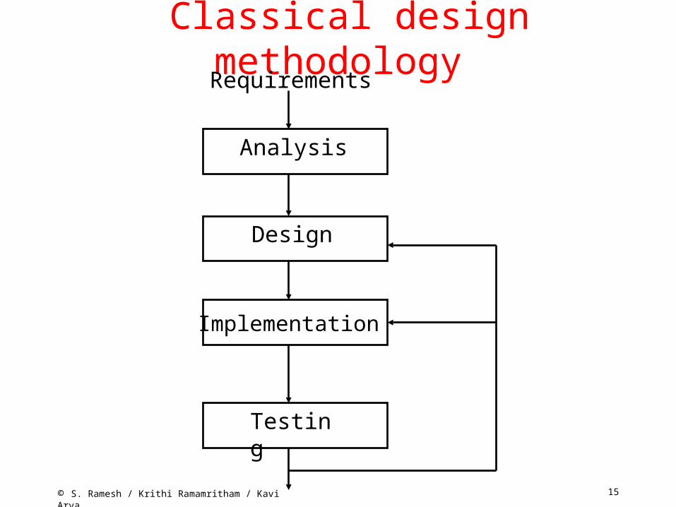
Classical design methodology
Analysis
Design
Implementation
Testing
Requirements
16© S. Ramesh / Krithi Ramamritham / Kavi Arya
Development Methodology• Simplified Picture of SW development
– Requirements Analysis – Design– Implementation (coding) – Verification and Validation– Bugs lead redesign or re-implementation
17© S. Ramesh / Krithi Ramamritham / Kavi Arya
Development Methodology• All steps (except implementation) are
informal– Processes and objects not well defined and
ambiguous– Design and requirement artifacts not precisely
defined– Inconsistencies and incompleteness– No clear relationship between different stages– Subjective, no universal validity – Independent analysis difficult– Reuse not possible
18© S. Ramesh / Krithi Ramamritham / Kavi Arya
Classical Methodology
• Totally inadequate for complex systems – Thorough reviews required for early bug
removal – Bugs often revealed late while testing – Traceability to Design steps not possible– Debugging difficult – Heavy redesign cost
• Not recommended for high integrity systems– Read embedded systems
19© S. Ramesh / Krithi Ramamritham / Kavi Arya
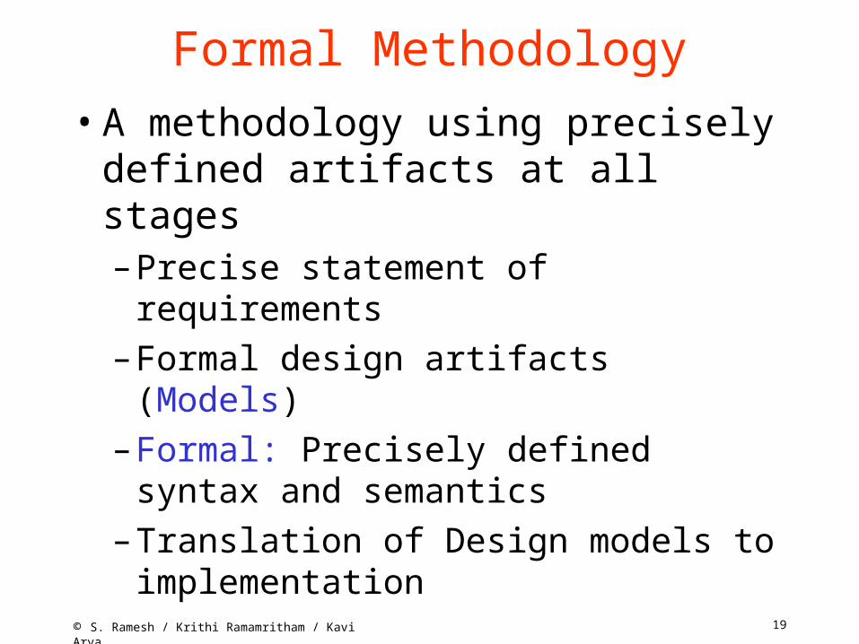
Formal Methodology• A methodology using precisely defined
artifacts at all stages– Precise statement of requirements– Formal design artifacts (Models)– Formal: Precisely defined syntax and
semantics– Translation of Design models to
implementation
20© S. Ramesh / Krithi Ramamritham / Kavi Arya
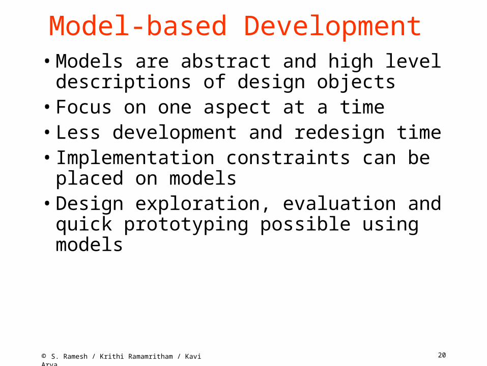
Model-based Development • Models are abstract and high level
descriptions of design objects• Focus on one aspect at a time • Less development and redesign time• Implementation constraints can be placed
on models• Design exploration, evaluation and quick
prototyping possible using models

21© S. Ramesh / Krithi Ramamritham / Kavi Arya
New Paradigm• Executable models essential
– Simulation• Can be rigorously validated
– Formal Verification • Models can be debugged and revised • Automatic generation of final code
– Traceability • The paradigm Model – Verify – Debug – CodeGenerate
22© S. Ramesh / Krithi Ramamritham / Kavi Arya
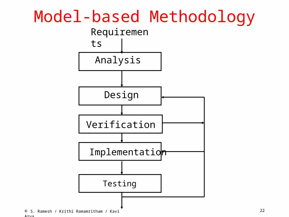
Model-based Methodology
Analysis
Design
Implementation
Testing
Requirements
Verification
23© S. Ramesh / Krithi Ramamritham / Kavi Arya
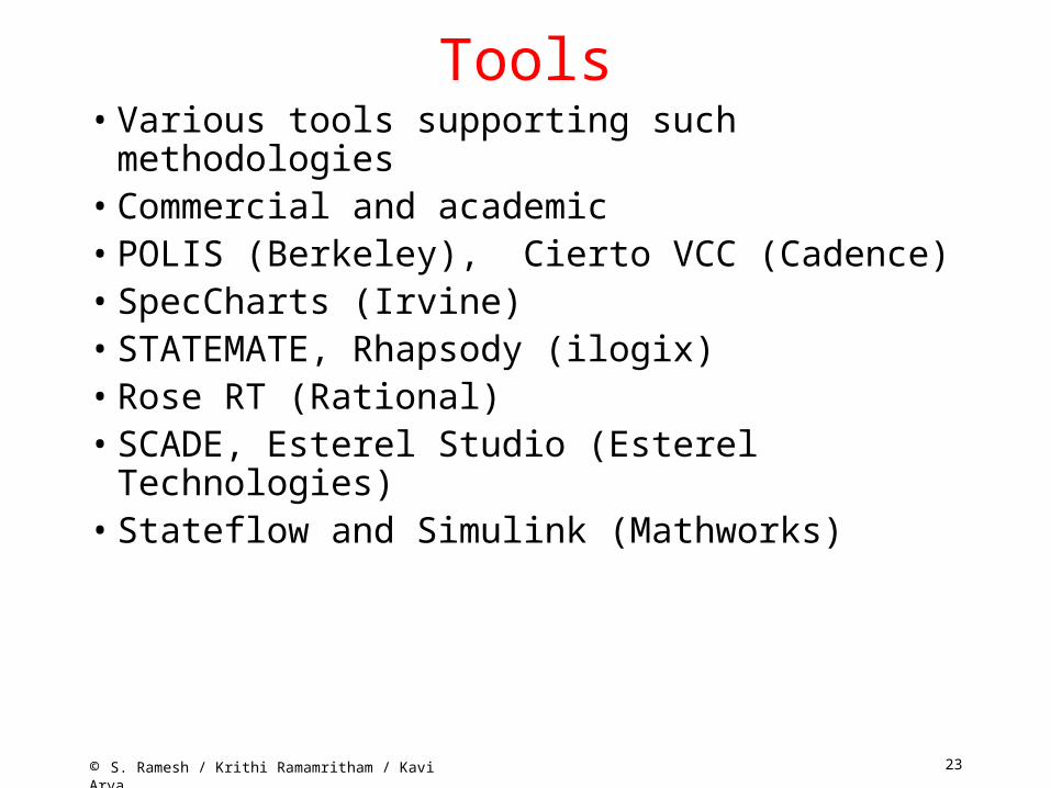
Tools• Various tools supporting such methodologies• Commercial and academic• POLIS (Berkeley), Cierto VCC (Cadence)• SpecCharts (Irvine)• STATEMATE, Rhapsody (ilogix)• Rose RT (Rational)• SCADE, Esterel Studio (Esterel Technologies)• Stateflow and Simulink (Mathworks)

24© S. Ramesh / Krithi Ramamritham / Kavi Arya
Modeling Languages • Models need to be formal• Languages for describing models• Various languages exist • High level programming languages (C, C++)• Finite State Machines, Statecharts, SpecCharts,
Esterel, Stateflow • Data Flow Diagrams, Lustre, Signal, Simulink • Hardware description languages (VHDL, Verilog) • Unified Modeling Language(UML)

25© S. Ramesh / Krithi Ramamritham / Kavi Arya
• Choice of languages depend upon the nature of computations modeled
• Seq. programming models for standard data processing computations
• Data flow diagrams for iterative data transformation
• State Machines for controllers• HDLs for hardware components
Modeling Languages

26© S. Ramesh / Krithi Ramamritham / Kavi Arya
Reactive Systems • Standard Software is a transformational
system • Embedded software is reactive
T. S.I O

27© S. Ramesh / Krithi Ramamritham / Kavi Arya
Reactive Systems
R. S.

28© S. Ramesh / Krithi Ramamritham / Kavi Arya
RS features • Non-termination• Ongoing continuous relationship with environment• Concurrency (at least system and environment) • Event driven • Events at unpredictable times • Environment is the master• Timely response (hard and soft real time) • Safety - Critical • Conventional models inadequate
29© S. Ramesh / Krithi Ramamritham / Kavi Arya
Finite State Machines
• One of the well-known models • Intuitive and easy to understand • Pictorial appeal • Can be made rigorous • Standard models for Protocols,
Controllers, HW
30© S. Ramesh / Krithi Ramamritham / Kavi Arya
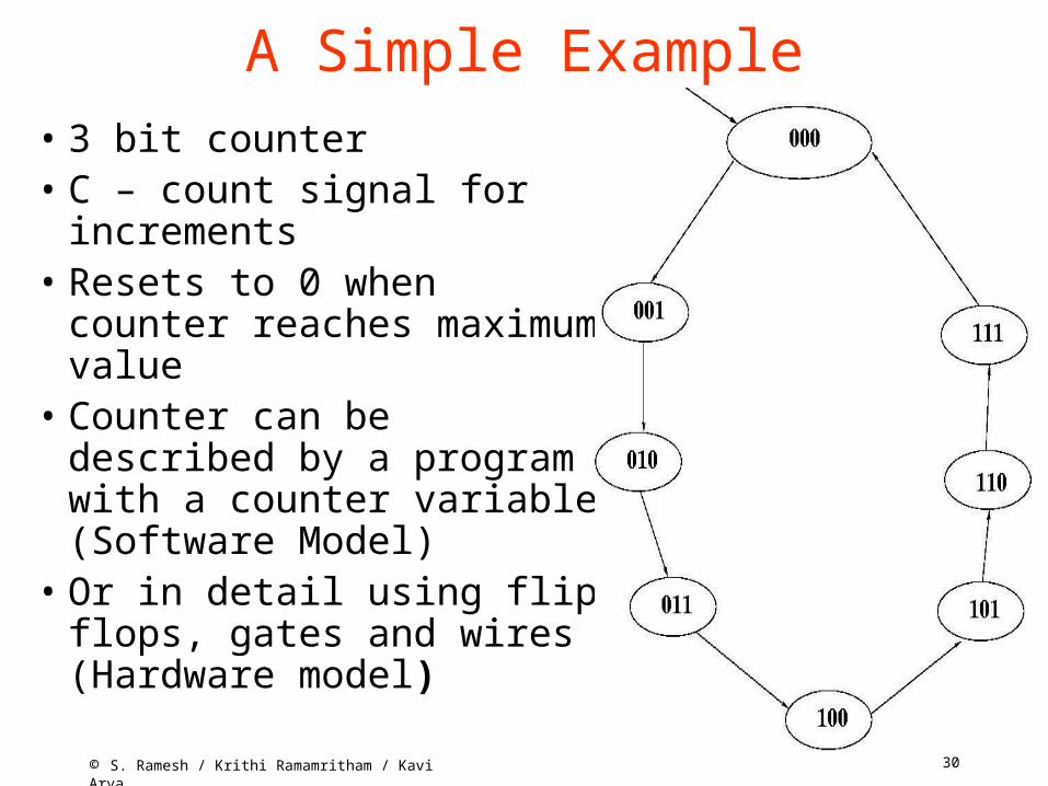
A Simple Example• 3 bit counter• C – count signal for
increments• Resets to 0 when counter
reaches maximum value• Counter can be described by
a program with a counter variable (Software Model)
• Or in detail using flip flops, gates and wires (Hardware model)
31© S. Ramesh / Krithi Ramamritham / Kavi Arya
State Machine Model• Counter behaviour naturally described by a
state machine• States determine the current value of the
counter• Transitions model state changes to the
event C.• Initial state determines the initial value of
the counter• No final state (why?)

32© S. Ramesh / Krithi Ramamritham / Kavi Arya
Precise Definition < Q, q0, S, T>
• Q – A finite no. of state names• q0 – Initial state• S – Edge alphabet
Abstract labels to concrete event, condition and action
• T – edge function or relation

33© S. Ramesh / Krithi Ramamritham / Kavi Arya
Semantics • Given the syntax, a precise semantics can
be defined• Set of all possible sequences of states and
edges• Each sequence starts with the initial state• Every state-edge-state triples are adjacent
states connected by an edge• Given a FSM, a unique set of sequences
can be associated• Language accepted by a FSM

34© S. Ramesh / Krithi Ramamritham / Kavi Arya
Abstract Models• Finite State machine model is abstract• Abstracts out various details
– How to read inputs?– How often to look for inputs?– How to represent states and transitions?– Focus on specific aspects
• Easy for analysis, debugging• Redesign cost is reduced• Different possible implementations
– Hardware or Software– Useful for codesign of systems
35© S. Ramesh / Krithi Ramamritham / Kavi Arya
Intuitive Models• FSM models are intuitive• Visual
– A picture is worth a thousand words• Fewer primitives – easy to learn, less
scope for mistakes and confusion• Neutral and hence universal applicability
– For Software, hardware and control engineers

36© S. Ramesh / Krithi Ramamritham / Kavi Arya
Rigorous Models• FSM models are precise and unambiguous• Have rigorous semantics• Can be executed (or simulated)• Execution mechanism is simple: An iterative scheme
state = initial_state loop case state: state 1: Action 1 state 2: Action 2 . . . end case end

37© S. Ramesh / Krithi Ramamritham / Kavi Arya
Code Generation• FSM models can be refined to different
implementation– Both HW and SW implementation– Exploring alternate implementations– For performance and other considerations
• Automatic code generation• Preferable over hand generated code• Quality is high and uniform
38© S. Ramesh / Krithi Ramamritham / Kavi Arya
States and Transitions
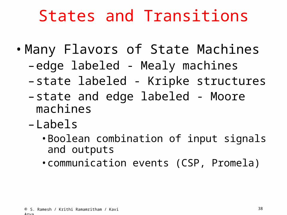
• Many Flavors of State Machines– edge labeled - Mealy machines– state labeled - Kripke structures– state and edge labeled - Moore machines – Labels
• Boolean combination of input signals and outputs• communication events (CSP, Promela)

39© S. Ramesh / Krithi Ramamritham / Kavi Arya
Another Example
A Traffic Light Controller• Traffic light at the intersection of High Way
and Farm Road• Farm Road Sensors (signal C)• G, R – setting signals green and red
• S,L - Short and long timer signal
• TGR - reset timer, set highway green and farm road red

40© S. Ramesh / Krithi Ramamritham / Kavi Arya
State Machine
41© S. Ramesh / Krithi Ramamritham / Kavi Arya
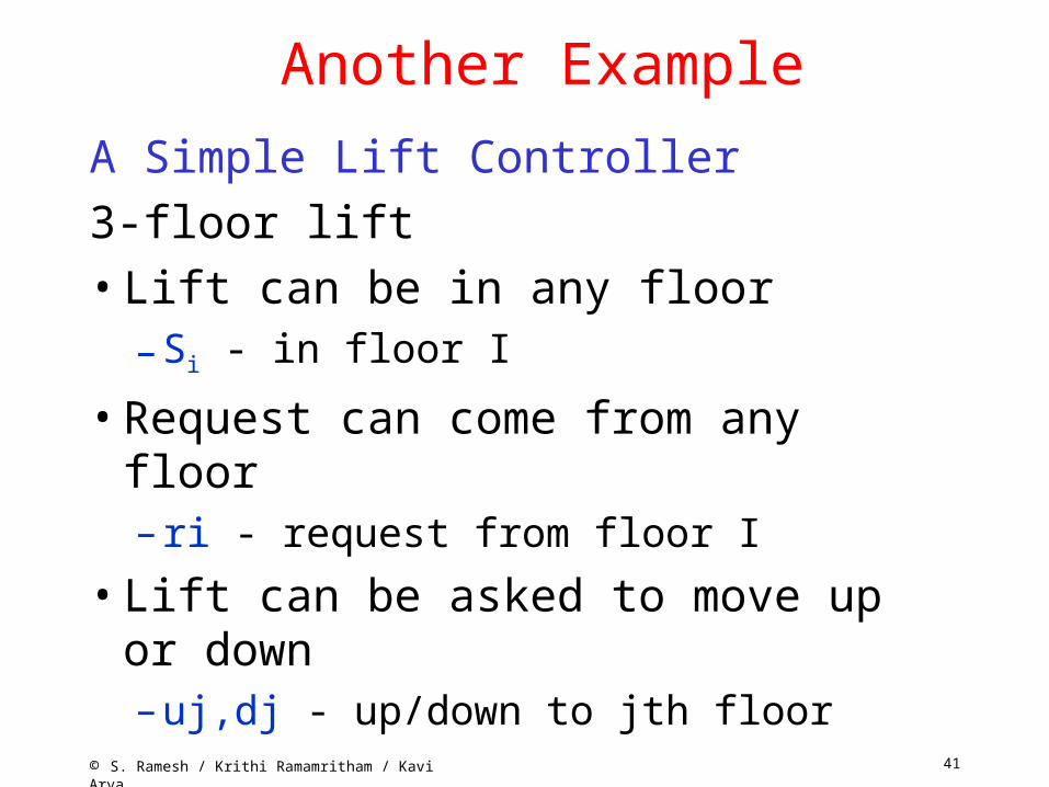
Another Example
A Simple Lift Controller3-floor lift• Lift can be in any floor
– Si - in floor I
• Request can come from any floor – ri - request from floor I
• Lift can be asked to move up or down – uj,dj - up/down to jth floor

42© S. Ramesh / Krithi Ramamritham / Kavi Arya
FSM model

43© S. Ramesh / Krithi Ramamritham / Kavi Arya
Nondeterminism• Suppose lift is in floor 2 (State S 2 )• What is the next state when when requests r1
and r3 arrive? – Go to S1
– Or go to S3
• The model non committal – allows both• More than one next state for a state and an input• This is called nondeterminism• Nondeterminism arises out of abstraction• Algorithm to decide the floor is not modeled• Models can be nondeterministic but not real lifts!
44© S. Ramesh / Krithi Ramamritham / Kavi Arya
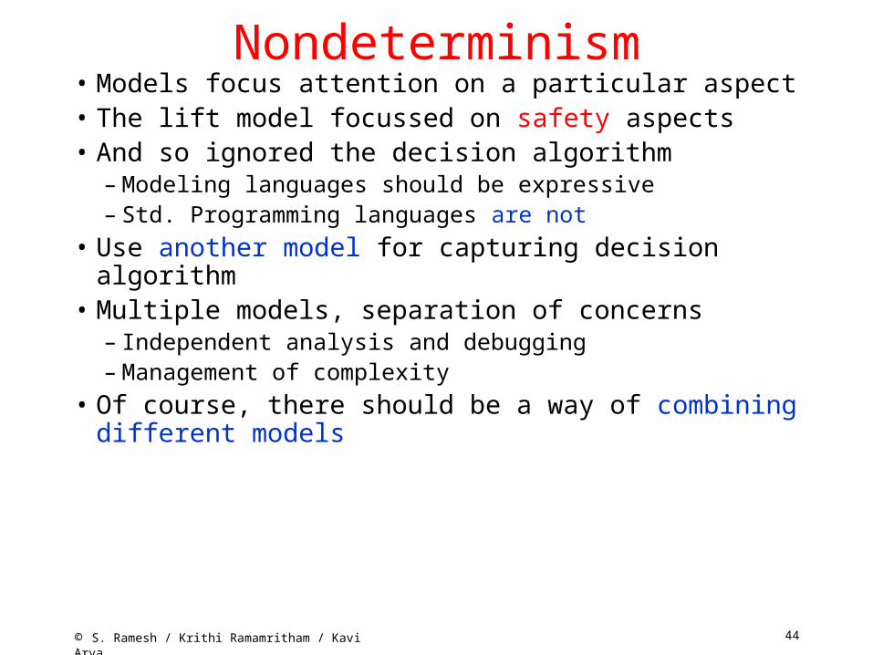
Nondeterminism• Models focus attention on a particular aspect• The lift model focussed on safety aspects• And so ignored the decision algorithm
– Modeling languages should be expressive– Std. Programming languages are not
• Use another model for capturing decision algorithm• Multiple models, separation of concerns
– Independent analysis and debugging– Management of complexity
• Of course, there should be a way of combining different models

45© S. Ramesh / Krithi Ramamritham / Kavi Arya
C-model enum floors {f1, f2, f3};
enum State {first, second, third};enum bool {ff, tt};enum floors req, dest; enum bool up, down = ff;enum State cur_floor = first;
req = read_req();
while (1){ switch (cur_floor) { case first: if (req == f2) {up = tt; dest = f2;} else if (req == f3) {up = tt; dest = f3;} else { up == ff; down = ff;}; break;

46© S. Ramesh / Krithi Ramamritham / Kavi Arya
C- modelcase second: if (req == f3)
{up = tt; dest = f3;} else if (req == f1) { up = ff; down = tt; dest = f1;} else { up == ff; down = ff;}; break;
case third: if (req == f2) {up = ff; down = tt; dest = f2;} else if (req == f1) { up = ff; down = tt; dest = f1;} else { up == ff; down = ff;}; break; }; /* end of switch */ req = read_req(); } /* end of while */
47© S. Ramesh / Krithi Ramamritham / Kavi Arya
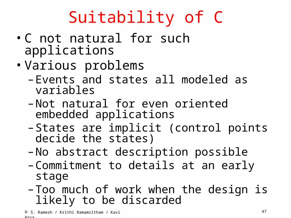
Suitability of C • C not natural for such applications• Various problems
– Events and states all modeled as variables– Not natural for even oriented embedded
applications – States are implicit (control points decide the
states) – No abstract description possible – Commitment to details at an early stage – Too much of work when the design is likely to be
discarded

48© S. Ramesh / Krithi Ramamritham / Kavi Arya
Exercise• Is the C model non-deterministic?
• What happens when two requests to go in different directions arrive at a state?
49© S. Ramesh / Krithi Ramamritham / Kavi Arya
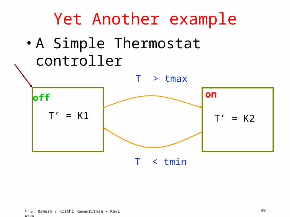
Yet Another example• A Simple Thermostat controller
T > tmax
T < tmin
onoff
T’ = K1 T’ = K2

50© S. Ramesh / Krithi Ramamritham / Kavi Arya
Summary• Finite number of states • Initial state • No final state (reactive system) • Non determinism (result of abstraction) • Edges labeled with events • Behavior defined by sequences of
transitions • Rigorous semantics • Easy to simulate and debug • Automatic Code generation

51© S. Ramesh / Krithi Ramamritham / Kavi Arya
Problems with FSMs • All is not well with FSMs• FSMs fine for small systems (10s of states)• Imagine FSM with 100s and 1000s of states
which is a reality• Such large descriptions difficult to understand • FSMs are flat and no structure• Inflexible to add additional functionalities• Need for structuring and combining different
state machines
52© S. Ramesh / Krithi Ramamritham / Kavi Arya
Statecharts• Extension of FSMs to have these features• Due to David Harel• Retains the nice features
– Pictorial appeal– States and transitions
• enriched with two features– Hierarchy and Concurrency
• States are of two kinds– OR state (Hierarchy)– AND state (concurrency)

53© S. Ramesh / Krithi Ramamritham / Kavi Arya
OR States• An OR state can have a whole state machine inside it• Example:
54© S. Ramesh / Krithi Ramamritham / Kavi Arya
OR states• When the system is in the state Count, it is
either in counting or not_counting• exactly in one of the inner states• Hence the term OR states (more precisely
XOR state)• When Count is entered, it will enter
not_counting – default state
• Inner states can be OR states (or AND states)
55© S. Ramesh / Krithi Ramamritham / Kavi Arya
OR states
• Both outer and inner states active simultaneously
• When the outer state exits, inner states also exited
• Priorities of transitions• Preemption (strong and weak)
56© S. Ramesh / Krithi Ramamritham / Kavi Arya
Economy of Edges
• Every transition from outer state corresponds to many transitions from each of the inner states
• Hierarchical construct replaces all these into one single transition
• Edge labels can be complex

57© S. Ramesh / Krithi Ramamritham / Kavi Arya
And States• An Or state contains exactly one state machine• An And state contains two or more state machines • Example:
58© S. Ramesh / Krithi Ramamritham / Kavi Arya
Example• Counting is an And state with three state
machines• S1, S2, S3, concurrent components of the
state• When in state Counting, control resides
simultaneously in all the three state machines• Initially, control is in C0, B0 and A0• Execution involves, in general, simultaneous
transitions in all the state machines

59© S. Ramesh / Krithi Ramamritham / Kavi Arya
Example (contd.)• When in state C0, B1, A2, clock signal
triggers the transition to B2 and A2 in S2 and S3
• When in C0, B2, A2, clock signal input trigger the transitions to C1, B0 and A0 in all S1, S2, S3
• And state captures concurrency• Default states in each concurrent
component

60© S. Ramesh / Krithi Ramamritham / Kavi Arya
Economy of States
• An AND-state can be flattened to a single state machine
• Will result in exponential number of states and transitions
• AND state is a compact and intuitive representation
61© S. Ramesh / Krithi Ramamritham / Kavi Arya
Counting• What are the three components of the state?• They represent the behaviour of the three bits of a counter• S3 – the least significant bit, S2 the middle one and S1
the most significant bit• Compare this with the flat and monolithic description of
counter state machine given earlier• Which is preferable?• The present one is robust - can be redesigned to
accommodate additional bits• Look at the complete description of the counter

62© S. Ramesh / Krithi Ramamritham / Kavi Arya
Complete Machine

63© S. Ramesh / Krithi Ramamritham / Kavi Arya
Communication• Concurrent components of AND state communicate with
each other• Taking an edge requires certain events to occur• New signals are generated when an edge is taken• These can trigger further transitions in other components• A series of transitions can be taken as a result of one
transition triggered by environment event• Different kinds of communication primitives• More on this later
64© S. Ramesh / Krithi Ramamritham / Kavi Arya
Flat State Machines• Capture the behaviour of the counter using
FSMs• Huge number of states and transitions• Explosion of states and transitions• Statechart description is compact • Easy to understand• Robust• Can be simulated• Code generation is possible• Execution mechanism is more complex
65© S. Ramesh / Krithi Ramamritham / Kavi Arya
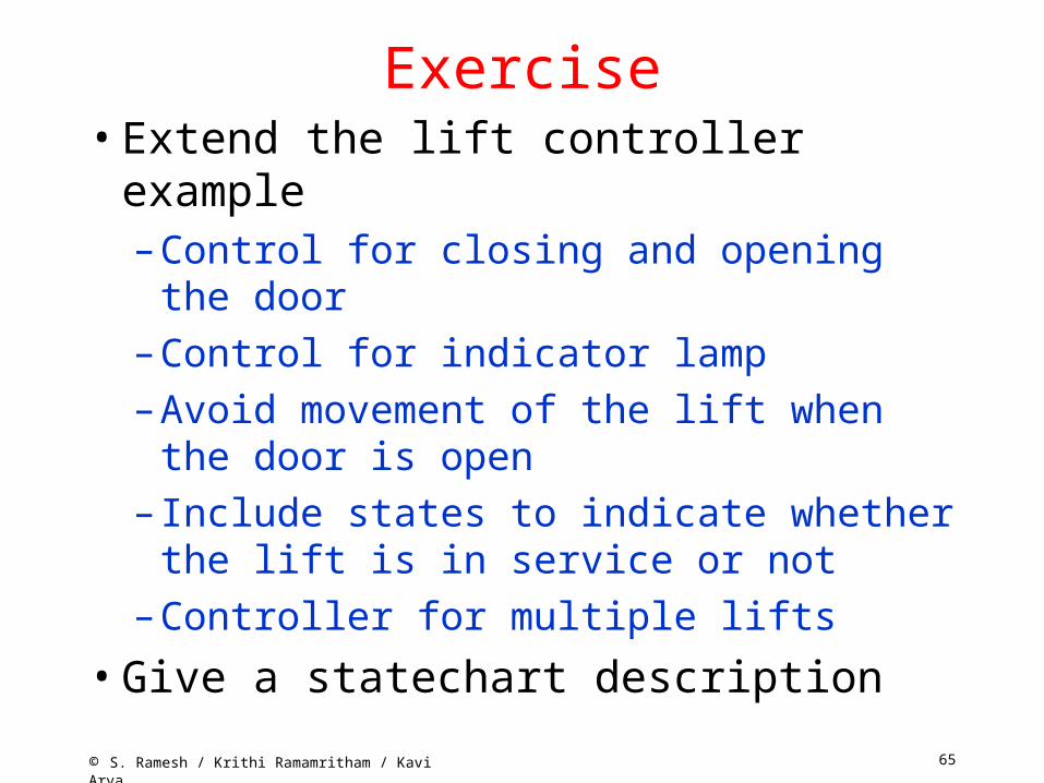
Exercise• Extend the lift controller example
– Control for closing and opening the door– Control for indicator lamp– Avoid movement of the lift when the door is
open– Include states to indicate whether the lift is in
service or not– Controller for multiple lifts
• Give a statechart description

66© S. Ramesh / Krithi Ramamritham / Kavi Arya
Extensions to Statecharts • various possibilities explored • adding code to transitions • to states • complex data types and function calls• Combining textual programs with statecharts• Various commercial tools exist• Statemate and Rhapsody (ilogix)• UML tools (Rational rose) • Stateflow (Mathworks) • SynchCharts (Esterel Technologies)
67© S. Ramesh / Krithi Ramamritham / Kavi Arya
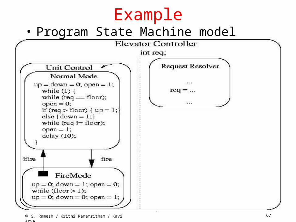
Example• Program State Machine model
68© S. Ramesh / Krithi Ramamritham / Kavi Arya
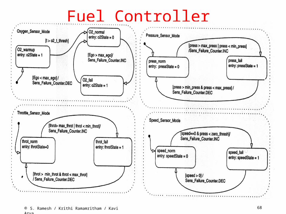
Fuel Controller

69© S. Ramesh / Krithi Ramamritham / Kavi Arya
Fuel Controller (Contd.)

70© S. Ramesh / Krithi Ramamritham / Kavi Arya
More Exercises• Construct the State machine models of
– Critical Section Problem– Producer-Consumer Problem– Dining Philosopher Problem
• And argue the correctness of solutions• Formal Analysis and Verification (more on
this later)

71© S. Ramesh / Krithi Ramamritham / Kavi Arya
Other Models • Synchronous Reactive Models
– useful for expressing control dominated application
– rich primitives for expressing complex controls – Esterel (Esterel Technologies) – More on this later
72© S. Ramesh / Krithi Ramamritham / Kavi Arya
Design Features• Two broad classifications
– Control-dominated designs– Data-dominated Designs
• Control-dominated designs– Input events arrive at irregular and
unpredictable times– Time of arrival and response more crucial
than values

73© S. Ramesh / Krithi Ramamritham / Kavi Arya
Design Features• Data-dominated designs
– Inputs are streams of data coming at regular intervals (sampled data)
– Values are more crucial– Outputs are complex mathematical functions
of inputs– numerical computations and digital signal
processing computations

74© S. Ramesh / Krithi Ramamritham / Kavi Arya
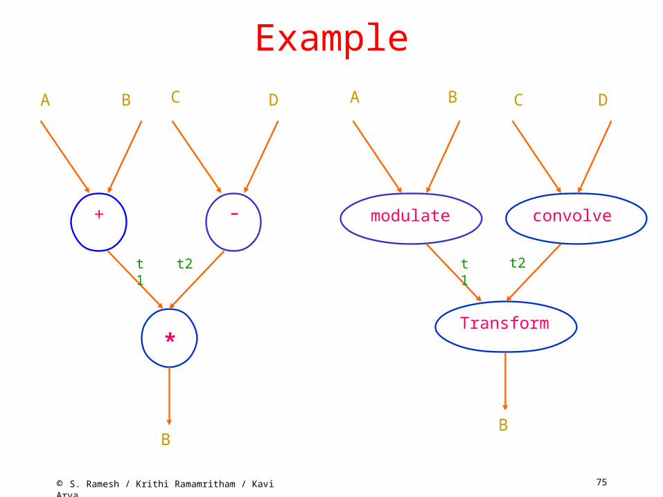
• State machines, Statecharts, Esterel are good for control-dominated designs
• Date flow models are useful for data-dominated systems
• Special case of concurrent process models• System behaviour described as an interconnection
of nodes• Each node describes transformation of data• Connection between a pair of nodes describes the
flow of data between from one node to the other
Data flow Models
75© S. Ramesh / Krithi Ramamritham / Kavi Arya
Example
+ -
*
modulate convolve
Transform
A B AC D B C D
t1 t2 t1 t2
BB

76© S. Ramesh / Krithi Ramamritham / Kavi Arya
Data Flow Models• Graphical Languages with support for
– Simulation, debugging, analyisis– Code generation onto DSP and micro
processors• Analysis support for hardware-software
partitioning• Many commercial tools and languages
– Lustre, Signal – SCADE
77© S. Ramesh / Krithi Ramamritham / Kavi Arya
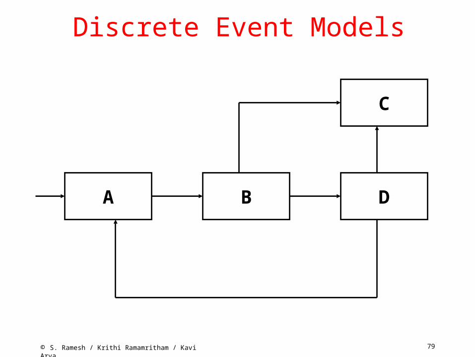
Discrete Event Models• Used for HW systems• VHDL, Verilog• Models are interconnection of nodes• Each node reacts to events at their inputs• Generates output events which trigger
other nodes

78© S. Ramesh / Krithi Ramamritham / Kavi Arya
DE Models• External events initiates a reaction• Delays in nodes modeled as delays in
event generation• Simulation• Problems with cycles• Delta cycles in VHDL
79© S. Ramesh / Krithi Ramamritham / Kavi Arya
Discrete Event Models
A B
C
D

80© S. Ramesh / Krithi Ramamritham / Kavi Arya

81© S. Ramesh / Krithi Ramamritham / Kavi Arya
82© S. Ramesh / Krithi Ramamritham / Kavi Arya
Some more exercise• Give a more detailed model of the digital
camera– Only certain data flow aspect of the camera is
given in the class (and in the book)

83© S. Ramesh / Krithi Ramamritham / Kavi Arya
Summary • Various models reviewed
– Sequential programming models – Hierarchical and Concurrent State Machines– Data Flow Models, Discrete Event Models
• Each model suitable for particular applications • State Machines for event-oriented control
systems

84© S. Ramesh / Krithi Ramamritham / Kavi Arya
Summary• Sequential program model, data flow
model for function computation • Real systems often require mixture of
models• Modeling tools and languages should have
combination of all the features– Ptolemy (Berkeley)

85© S. Ramesh / Krithi Ramamritham / Kavi Arya
References• F. Balarin et al., Hardware – Software Co-design
of Embedded Systems: The POLIS approach, Kluwer, 1997
• N. Halbwachs, Synch. Prog. Of Reactive Systems, Kluwer, 1993
• D. Harel et al., STATEMATE: a working environment for the development of complex reactive systems, IEEE Trans. Software Engineering, Vol. 16 (4), 1990.
• J. Buck, et al., Ptolemy: A framework for simulating and prototyping heterogeneous systems, Int. Journal of Software Simulation, Jan. 1990