+. simple electrical circuit pictorial simple electrical circuit schematic
TRANSCRIPT

+

Simple Electrical Circuitpictorial

Simple Electrical Circuitschematic

A voltage divider used for volume control.
Block Diagram Drawing

Standard symbol for a dc voltage source.


electrical schematic of flashlight
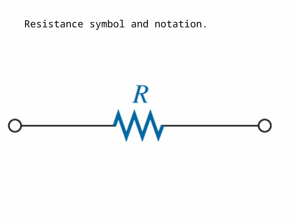
Resistance symbol and notation.

Film resistors:

FIG. 3.25 Color coding for fixed resistors.

Color-code bands on a resistor
• 1st band is the first digit of the resistance value• 2nd band is the second digit of the resistance
value• 3rd band is the multiplier (number of zeros)• 4th band indicates the tolerance

Color coding.

Standard Values of Resistors

Potentiometer control of voltage levels.

Potentiometer and rheostat symbols and basic construction of one type of potentiometer.

Typical potentiometers and two construction views.

Typical fuses and circuit breakers and their symbols.

Common Ground Symbol

Circuit Ground
• Voltage is relative• The voltage at one point in a circuit is
always measured relative to another point• This reference point in a circuit is usually
the ground point

Voltage sources and grounds
Notation
Ground symbol Voltage source
symbol


Symbols for ground.

A simple circuit with ground connections.
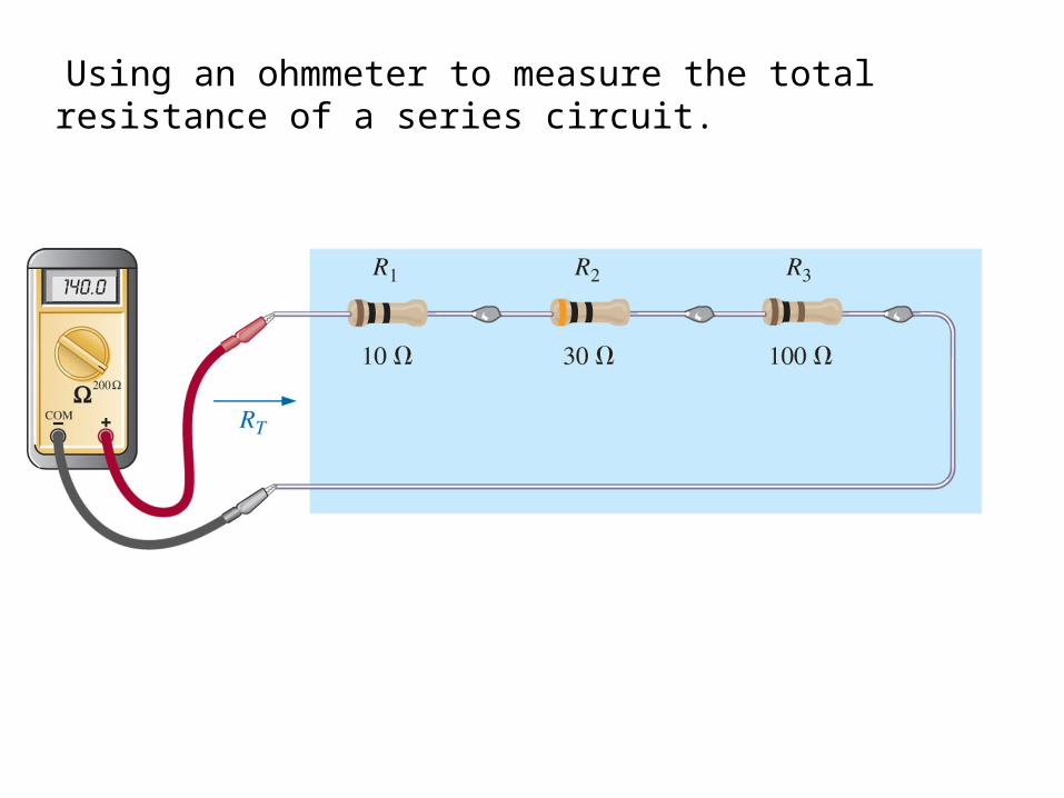
Using an ohmmeter to measure the total resistance of a series circuit.

Schematic representation for a dc series circuit.

Parallel combination of resistors.Same resistance value
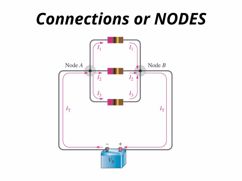
Connections or NODES

The voltage divider as a bias circuit for a transistor amplifier.

Symbol for the inductor.

Typical Inductors

Relative sizes of different types of inductors: (a) toroid, high-current; (b) phenolic (resin or plastic core); (c) ferrite core.

Symbols for the capacitor: (a) fixed; (b) variable.

(a) Film/foil polyester radial lead; (b) metalized polyester-film axial lead; (c) surface-mount polyester-film; (d) polypropylene-film, radial lead.
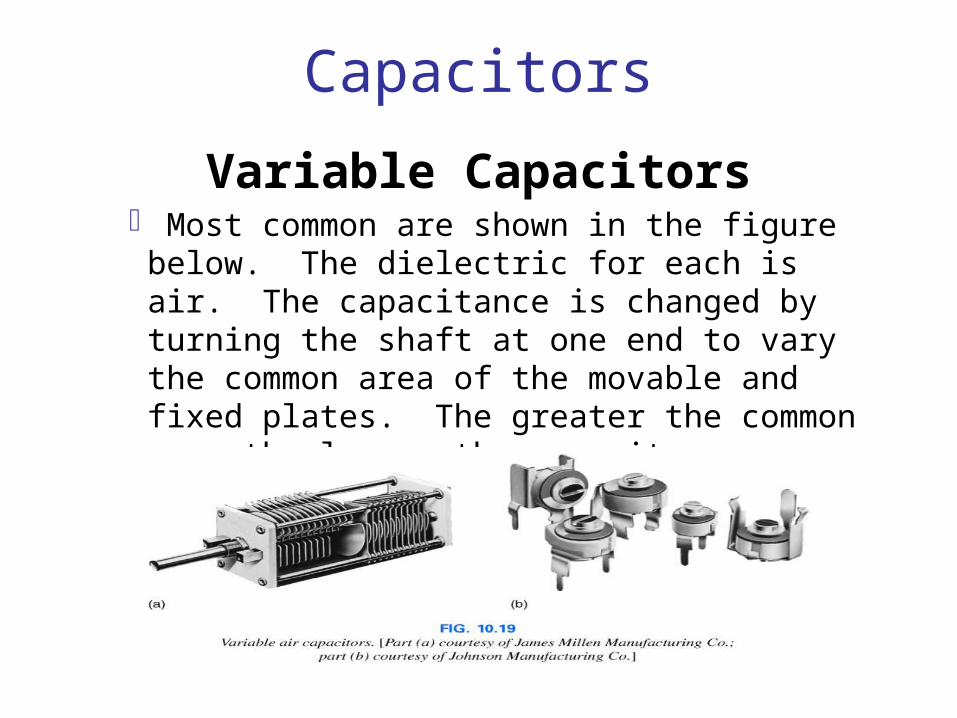
Capacitors
Variable Capacitors Most common are shown in the figure below. The
dielectric for each is air. The capacitance is changed by turning the shaft at one end to vary the common area of the movable and fixed plates. The greater the common area the larger the capacitance.

Symbol for a sinusoidal voltage source.
Volts A.C.

Some common types of transformers(step AC voltage up or down)

Schematic symbols specify the type of core.

Utility-pole transformer in a typical power distribution system.
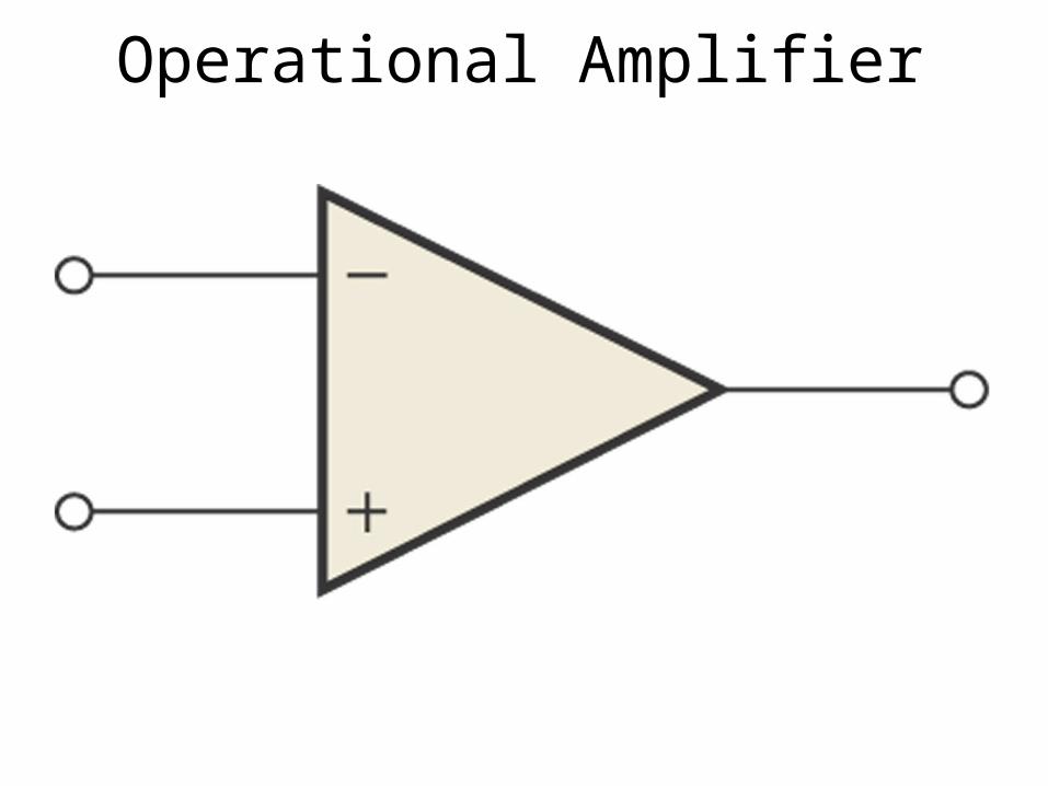
Operational Amplifier
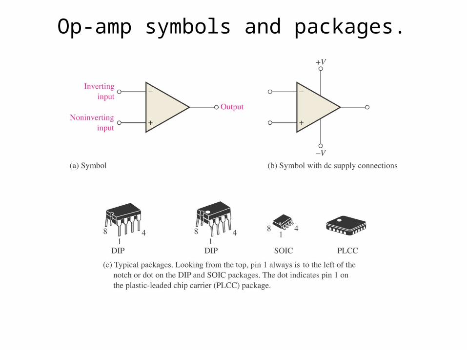
Op-amp symbols and packages.
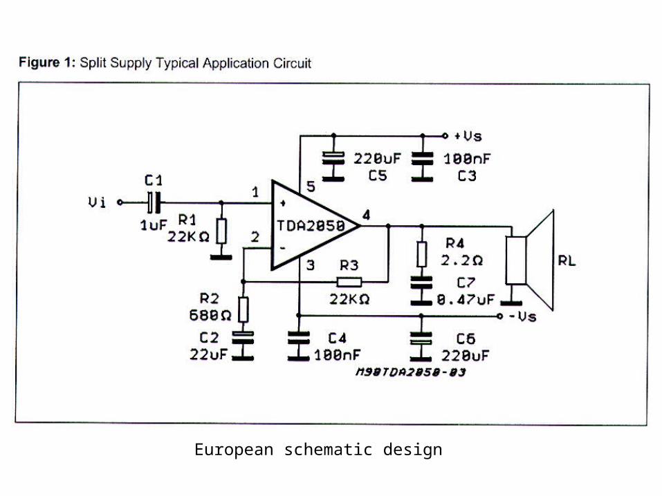
European schematic design

European schematic design

Transistors


Amplifier Output stage

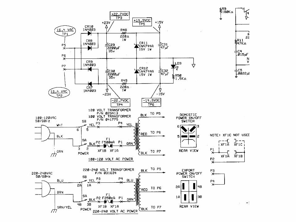
D.C. 5volt Power Supply

Connections
• Wire To pass current very easily from one part of a circuit to another
• A ‘DOT' should be drawn where wires are connected (joined), but it is sometimes omitted.

Connections
• In complex diagrams it is often necessary to draw wires crossing even though they are not connected, the 'bridge' symbol shown on the right is preferred because the simple crossing on the left may be misread as a join where you have forgotten to add a ‘DOT'!

Test Instruments
A voltmeter is used to measure voltage. The proper name for voltage is 'potential difference', but most people prefer to say voltage!
An ammeter is used to measure current.

Test Instruments
An ohmmeter is used to measure resistance. Most multimeters have an ohmmeter setting.
A galvanometer is a very sensitive meter which is used to measure tiny currents, usually 1mA or less.

Solid Core hook-up wire
This is one solid wire with a plastic coating available in a wide variety of colors. It can be bent to shape but will break if repeatedly flexed. Use it for connections which will not be disturbed, for example links between points of a circuit board.

Stranded wire
This consists of many fine strands of wire covered by an outer plastic coating. It is flexible and can withstand repeated bending without breaking. Use it for connections which may be disturbed, for example wires outside cases to sensors and switches. A very flexible version ('extra-flex') is used for test leads

Signal cable
Signal cable consists of several color-coded cores of stranded or solid core wire housed within an outer plastic sheath. it is suitable for low voltage, low current signals where screening from electrical interference is not required.
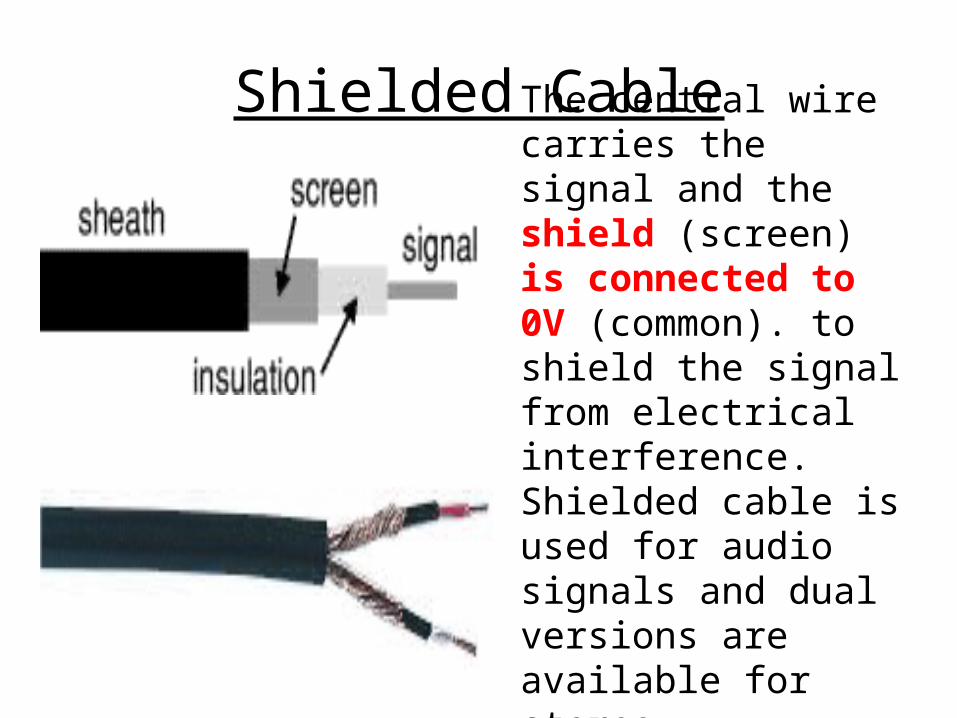
Shielded Cable
The central wire carries the signal and the shield (screen) is connected to 0V (common). to shield the signal from electrical interference. Shielded cable is used for audio signals and dual versions are available for stereo.

Co-axial cable
This type of shielded cable is designed to carry high frequency signals such as those found in cable TV connections and oscilloscope leads.
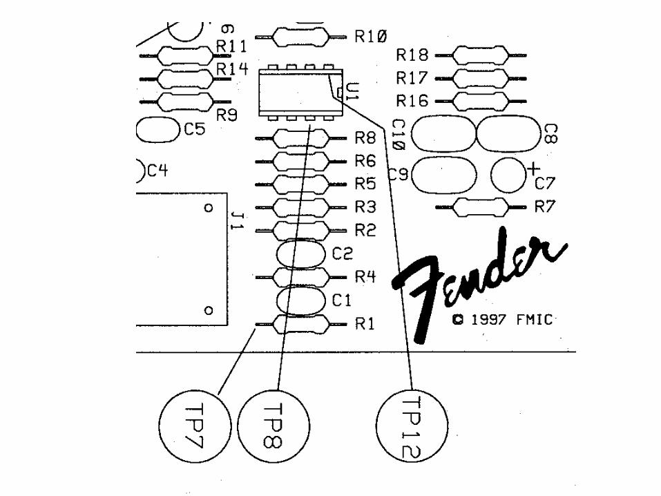
Fender Musical Instruments
Frontman 15G Amplifier
Schematic and Parts Layout READING