gstq001...telecontrol equipment and systems - part 5-101: transmissionprotocols - companion standard...
TRANSCRIPT

GLOBAL STANDARD Page 1 of 30
Fixed installed indoor Power Quality Instrument GSTQ001
Rev. 02 05/04/2019
Fixed installed indoor Power Quality Instrument
This global standard define the characteristics of the fixed installed indoor Power Quality Instrument (according to IEC 62586-1) and accessories for measurement of power quality parameters in a.c. distribution systems with a declared fundamental frequency of 50 Hz or 60 Hz.
This document is intellectual property of Enel Spa; reproduction or distribution of its contents in any way or by any means whatsoever is subject to the prior approval of the above mentioned company which will safeguard its rights under the civil and penal codes.
It is for internal Use. Each Country can provide a translation in local language but the official reference document is this GS English version.
Revision Data List of modifications
00 13.11.2015 First draft
01 29.01.2016 First approved edition
02 05.04.2019 Second approved edition. Introduction of PQI-A-FI2-G and PQI-S-FI2-G families. Remodulation of several requirements from basic to extended. New extended requirements.
Countries’ I&N Elaborated by Collaborations by Verified by Approved by
Argentina - - - Carlos Espinoza
Brazil - - Elio Vicentini Ricardo Brandão
Darcio Dias
Chile - - - Daniel Gonzalez
Colombia - - - Juan Gomez
Iberia Jose Maria Romero Gordon
- Jose Maria Romero Gordon
Maria Avery Fernandez
Italy Stefano Riva - Giorgio Scrosati Gianluca Sapienza
Peru - - - Robert Sanchez
Romania - - - Vasilica Obrejan
Elaborated by Collaborations by Verified by Approved by
Global I&N – NTI Christian Noce - Christian Noce Fabio Giammanco

GLOBAL STANDARD Page 2 of 30
Fixed installed indoor Power Quality Instrument GSTQ001
Rev. 02 05/04/2019
INDEX
1 ACRONYMS ................................................................................................................. 5
2 LIST OF COMPONENTS, PRODUCT FAMILY OR SOLUTIONS TO WHICH THE GS APPLIES .............................................................................................................................. 7
3 NORMATIVE REFERENCES AND BIBLIOGRAPHY ................................................ 10
3.1 For all countries ............................................................................................................................. 10
3.2 For EU countries ............................................................................................................................ 10
3.3 For Italy ........................................................................................................................................... 11
3.4 For Brazil ......................................................................................................................................... 11
3.5 For Colombia .................................................................................................................................. 11
4 REPLACED STANDARDS ......................................................................................... 12
5 APPLICATION FIELDS .............................................................................................. 13
6 PQI BASIC REQUIREMENTS .................................................................................... 14
6.1 Enclosure ........................................................................................................................................ 14
6.2 Power supply .................................................................................................................................. 14
6.3 Phisical buttons and leds .............................................................................................................. 15
6.4 Measuring input channels ............................................................................................................. 15
6.4.1 Voltage input channels ................................................................................................................ 15 6.4.2 Direct current input channels ....................................................................................................... 15
6.5 Communication ports and expansion slots ................................................................................ 15
6.6 PQI management system .............................................................................................................. 15
6.7 Internal data storage ...................................................................................................................... 16
6.8 Synchronisation ............................................................................................................................. 16
6.9 IP stack ............................................................................................................................................ 17
6.10 Data exchange with PQMS ............................................................................................................ 17
6.10.1 PQdif data exchange ................................................................................................................... 17 6.10.2 HTTP/HTTPs REST server .......................................................................................................... 18
6.11 Trends registration ........................................................................................................................ 18
6.12 Triggered events registration ....................................................................................................... 18
6.13 Crucial system events registration .............................................................................................. 20
7 PQI EXTENDED REQUIREMENTS ............................................................................ 21
7.1 Power supply enhancement .......................................................................................................... 21
7.2 Current input channels enhancement ......................................................................................... 21
7.3 Other input and output channels enhancement ......................................................................... 21

GLOBAL STANDARD Page 3 of 30
Fixed installed indoor Power Quality Instrument GSTQ001
Rev. 02 05/04/2019
7.4 Expansion ports ............................................................................................................................. 21
7.5 Voltage dip monitoring according to Italian Regulation enhancement .................................... 22
7.6 Energy measurement enhancement ............................................................................................ 22
7.7 Mains signalling voltage enhancement ....................................................................................... 22
7.8 Specific RTU functionalities according to Spanish requirements enhancement ................... 22
7.9 IEC 61850 enhancement ................................................................................................................ 22
7.10 Triggered events registration enhancement ............................................................................... 22
7.11 Trends registration enhancement ................................................................................................ 23
7.12 Configuration file enhancement ................................................................................................... 24
7.13 Communication enhancement ...................................................................................................... 24
8 PQI ACCESSORIES ................................................................................................... 25
8.1 Cables .............................................................................................................................................. 25
8.2 Modem kit ........................................................................................................................................ 25
8.3 GPS kit ............................................................................................................................................. 25
9 TESTING AND CERTIFICATIONS ............................................................................. 27
9.1 Testing ............................................................................................................................................. 27
9.2 IEC 61000-4-30 certification .......................................................................................................... 27
9.3 Certifications or self-certifications of calibration ....................................................................... 27
9.4 Other certifications and self-certifications .................................................................................. 27
9.5 RSE certification ............................................................................................................................ 27
10 MISCELLANEOUS ..................................................................................................... 28
10.1 Required documentation ............................................................................................................... 28
10.2 Clarification during procurement process .................................................................................. 28
10.3 Amendement................................................................................................................................... 28
10.4 PQI delivery form ........................................................................................................................... 28
10.5 Typical configuration ..................................................................................................................... 29

GLOBAL STANDARD Page 4 of 30
Fixed installed indoor Power Quality Instrument GSTQ001
Rev. 02 05/04/2019
FIGURES
Figure 1 – Illustrative example of PQI type B arrangement 14
Figure 2 – PQI RJ12 pinouts 17
Figure 3 – Pre-trigger and post event times 20
TABLES
Table 1 – PQI product family and description ................................................................................................ 7
Table 2 – PQI accessories ................................................................................................................................ 8
Table 3 – Triggered events registration ........................................................................................................ 18
Table 4 – Output/Input channel charateristics ............................................................................................. 21
Table 5 – Analog outputs current in case of power frequency ................................................................... 21
Table 6 – Trends registration ......................................................................................................................... 23
Table 7 – Most typical configurations. .......................................................................................................... 29

GLOBAL STANDARD Page 5 of 30
Fixed installed indoor Power Quality Instrument GSTQ001
Rev. 02 05/04/2019
1 ACRONYMS
a. 1PPS A pulse per second signal
b. CLI Caller Line Identification
c. CS Current Sensor
d. CSV Comma-separated values
e. DHCP Dynamic Host Configuration Protocol
f. DHCPv6 Dynamic Host Configuration Protocol (IPv6)
g. DNP3 Distributed Network Protocol
h. DNS Domain Name System
i. GPS Global Positioning System
j. GPSA GPS Accessories
k. GPSR GPS Receiver Time Syncro Receiver
l. GS Enel Global Standard
m. HMI Human-Machine Interface
n. HTTP Hypertext Transfer Protocol
o. HTTPS Hypertext Transfer Protocol Secure
p. JSON JavaScript Object Notation
q. M3G Modem GSM – GPRS – UMTS (2G + 3G)
r. NTP Network Time Protocol
s. NTP Network Time Protocol
t. PIMS PQI management system
u. PQ Power Quality
v. PQI Power Quality Instrument according to IEC 62586-1
w. PQIA Power Quality Instrument Accessories
x. PQMS Power Quality Management System
y. REST Representational State Transfer
z. RTU Remote Terminal Unit

GLOBAL STANDARD Page 6 of 30
Fixed installed indoor Power Quality Instrument GSTQ001
Rev. 02 05/04/2019
aa. SIM Subscriber Identity Module
bb. SMA SubMiniature connector version A
cc. TCP Transmission Control Protocol
dd. UPS Uninterruptible Power Supply
ee. VS Voltage Sensor

GLOBAL STANDARD Page 7 of 30
Fixed installed indoor Power Quality Instrument GSTQ001
Rev. 02 05/04/2019
2 LIST OF COMPONENTS, PRODUCT FAMILY OR SOLUTIONS TO WHICH THE GS APPLIES
The Power Quality Instrument (PQI) described in this GS is inside the category PQI-A by according to IEC 62586-1 and it can be classified in three classes provided in Table 1.
Table 1 – PQI product family and description
PQI type Product family code Description
PQI-A-FI2-G type R PQI-A-FI2-G PQI rack 19” mounting
PQI-A-FI2-G type W PQI-A-FI2-G PQI wall mounting with plugs
PQI-A-FI2-G type D PQI-A-FI2-G PQI top hat rail 35 X 15 mounting
PQI-A-FI2-G type B PQI-A-FI2-G PQI Half rack 19” mounting
PQI-S-FI2-G type R PQI-S-FI2-G PQI rack 19” mounting
PQI-S-FI2-G type W PQI-S-FI2-G PQI wall mounting with plugs
PQI-S-FI2-G type D PQI-S-FI2-G PQI top hat rail 35 X 15 mounting
PQI-S-FI2-G type B PQI-S-FI2-G PQI Half rack 19” mounting
PQI-A-FI1-H type R PQI-A-FI1-H PQI rack 19” mounting
PQI-A-FI1-H type W PQI-A-FI1-H PQI wall mounting with plugs
PQI-A-FI1-H type D PQI-A-FI1-H PQI top hat rail 35 X 15 mounting
PQI-A-FI1-H type B PQI-A-FI1-H PQI Half rack 19” mounting
Power supply enhancement PQI enhancement See par. 7.1
Output channels enhancement PQI enhancement See par. 7.2
Voltage dip monitoring according to Italian Regulation enhancement
PQI enhancement See par. 7.4
Energy measurement enhancement PQI enhancement See par. 7.6
Mains signalling voltage enhancement PQI enhancement See par. 7.7
GLOBAL STANDARD Page 8 of 30
Fixed installed indoor Power Quality Instrument GSTQ001
Rev. 02 05/04/2019
Specific RTU functionalities according to Spanish requirements enhancement
PQI enhancement See par. 7.8
IEC 61850 enhancement PQI enhancement See par. 7.9
Triggered events registration enhancement
PQI enhancement See par. 7.10
Trends registration enhancement PQI enhancement See par. 7.11
Configuration file enhancement PQI enhancement See par. 7.12
Typical PQI type R Italy PQI enhancement See par. 10.5
Typical PQI type R Spain PQI enhancement See par. 10.5
Typical PQI type D Spain PQI enhancement See par. 10.5
Typical PQI type R Romania PQI enhancement See par. 10.5
Typical PQI type B Chile PQI enhancement See par. 10.5
Typical PQI type W Brazil PQI enhancement See par. 10.5
Typical PQI type P Colombia PQI enhancement See par. 10.5
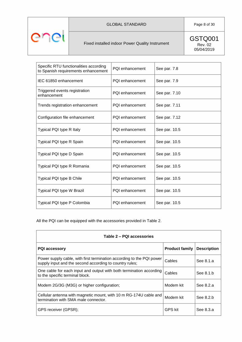
All the PQI can be equipped with the accessories provided in Table 2.
Table 2 – PQI accessories
PQI accessory Product family Description
Power supply cable, with first termination according to the PQI power supply input and the second according to country rules;
Cables See 8.1.a
One cable for each input and output with both termination according to the specific terminal block.
Cables See 8.1.b
Modem 2G/3G (M3G) or higher configuration; Modem kit See 8.2.a
Cellular antenna with magnetic mount, with 10 m RG-174U cable and termination with SMA male connector.
Modem kit See 8.2.b
GPS receiver (GPSR); GPS kit See 8.3.a

GLOBAL STANDARD Page 9 of 30
Fixed installed indoor Power Quality Instrument GSTQ001
Rev. 02 05/04/2019
20 m cable for connection to PQI, both termination in RJ12; GPS kit See 8.3.b
GPS antenna with magnetic mount and/or wall plugs, with 5 m cable, with L bracket;
GPS kit See 8.3.c
extra bracket for wall mounting. GPS kit See 8.3.d

GLOBAL STANDARD Page 10 of 30
Fixed installed indoor Power Quality Instrument GSTQ001
Rev. 02 05/04/2019
3 NORMATIVE REFERENCES AND BIBLIOGRAPHY
All the references in this GS are intended in the last revision or amendement.
3.1 For all countries
IEC 60529 Degrees of protection provided by enclosures (IP code)
IEC 60715 Dimensions of low-voltage switchgear and controlgear - Standardized mounting on rails for mechanical support of switchgear, controlgear and accessories
IEC 61000 series Electromagnetic compatibility (EMC)
IEC 61006-5 Electromagnetic compatibility (EMC) - Part 6-5: Generic standards - Immunity for equipment used in power station and substation environment
CISPR 32 Electromagnetic compatibility of multimedia equipment – Emission requirements
IEC 61000-4-30 Electromagnetic compatibility (EMC) – Part 4-30: Testing and measurement techniques – Power quality measurement methods.
IEC 62586-1 Power quality measurement in power supply systems – Part 1: Power quality instruments (PQI).
IEC 62586-2 Power quality measurement in power supply systems – Part 2: Functional tests and uncertainty requirements.
IEC 61010-1 Safety requirements for electrical equipment for measurement, control, and laboratory use - Part 1: General requirements.
IEC 61010-2-032 Safety requirements for electrical equipment for measurement, control and laboratory use - Part 2-032: Particular requirements for hand-held and hand-manipulated current sensors for electrical test and measurement
IEC 60297-3-100 Mechanical structures for electronic equipment - Dimensions of mechanical structures of the 482,6 mm (19 in) series - Part 3-100: Basic dimensions of front panels, subracks, chassis, racks and cabinets.
ISO/IEC 7810 Identification cards - Physical characteristics
IEC 60870-5-104 Telecontrol equipment and systems - Part 5-104: Transmission protocols - Network access for IEC 60870-5-101 using standard transport profiles
IEC 60870-5-101 Telecontrol equipment and systems - Part 5-101: Transmissionprotocols - Companion standard for basic telecontrol tasks
IEC 62749 Assessment of power quality - Characteristics of electricity supplied by public networks
IEC 62053-22 Electricity metering equipment (a.c.) - Particular Requirements - Part 22: Static meters for active energy (classes 0,2 S and 0,5 S)
IEC 17065 Conformity assessment - Requirements for bodies certifying products, processes and services
IEC 61850 series Communication protocols for IED at electrical substation
IEEE 1159.3 IEEE Recommended Practice for the Transfer of Power Quality Data.
NMEA 0183 National Marine Electronics Association electrical signal requirements, data transmission protocol and time, and specific sentence formats for a 4800-baud serial data bus
GSTQ003 Power Quality Management System
GSTQ002 Extended Power Quality Data Interchange Formats
3.2 For EU countries

GLOBAL STANDARD Page 11 of 30
Fixed installed indoor Power Quality Instrument GSTQ001
Rev. 02 05/04/2019
EN 50160 Voltage characteristics of electricity supplied by public distribution systems.
EU directive 2004/108/CEE
EMC directive
EU directive 2006/95/CEE
Low Voltage directive
EU directive 93/68/CEE
CE marking directive
3.3 For Italy
RSE 12004159 Specifiche tecnico-funzionali delle apparecchiature di monitoraggio della qualità della tensione per le reti MT.
RSEpaper
R. Chiumeo, M. de Nigris, L. Garbero, C. Gandolfi, L. Tenti, E. Carpaneto, “Implementation of a New Method for an Improved Voltage Dips Evaluation by the Italian Power Quality Monitoring System in Presence of VT Saturation Effects”, International Conference on Renewable Energies and Power Quality (ICREPQ’10), Granada (Spain), 23rd to 25th March, 2010.
ARG/elt 198/11 Testo integrato della qualità dei servizi di distribuzione e misura dell’energia elettrica per il periodo di regolazione 2012-2015
3.4 For Brazil
PRODIST Módulo 8
Procedimentos de Distribuição de Energia Elétrica no Sistema Elétrico Nacional – Módulo 8 – Qualidade de Energia Elétrica Rev. 10
Procedimentos de Rede ONS– Submódulo 2.8
Gerenciamento dos indicadores de desempenho da rede básica e dos barramentos dos transformadores de fronteira, e de seus componentes
3.5 For Colombia
Resolución CREG 024 -2005
normas de calidad de la potencia eléctrica aplicables a los servicios de Distribución de Energía Eléctrica
Resolución CREG 016-2007
Por la cual se modifica parcialmente la Resolución CREG 024 de 2005 que establece las normas de calidad de la potencia eléctrica aplicables a la Distribución de Energía Eléctrica en el Sistema Interconectado Nacional.
Resolución CREG 065-2012
establece las normas de calidad de la potencia eléctrica aplicables en el Sistema Interconectado Nacional
Resolución CREG 038-2014
Por la cual se modifica el Código de Medida contenido en el Anexo general del Código de Redes

GLOBAL STANDARD Page 12 of 30
Fixed installed indoor Power Quality Instrument GSTQ001
Rev. 02 05/04/2019
4 REPLACED STANDARDS
Codification Country Title
DV908 Italy Apparecchiatura di monitoraggio della qualita’ della tensione delle reti elettriche MT
SNC021 Spain Convertidores de medida para potencias activa y reactiva, tensión e intensidad de uso general.

GLOBAL STANDARD Page 13 of 30
Fixed installed indoor Power Quality Instrument GSTQ001
Rev. 02 05/04/2019
5 APPLICATION FIELDS
The PQI will be installed in the HV, MV or LV distribution grid in order to meausure all the relevant PQ parameters. The relevant PQ parameters are defined in IEC 61000-4-30, IEC 62749 and EN 50160.
The installation will be a substation or another indoor premise in a country where one or more utilities are under Enel control.
The PQI must include RTU functionalities in order to allow data exchange (according to GSTQ002) with the PQMS. The PQMS is the Power Quality Management System (according to GSTQ003), including data acquisition from PQI.
Security by design is mandatory for any devices developed to be installed in the ENEL premises; the Enel requirements will be declared during the procurement process (par. 10.2).

GLOBAL STANDARD Page 14 of 30
Fixed installed indoor Power Quality Instrument GSTQ001
Rev. 02 05/04/2019
6 PQI BASIC REQUIREMENTS
According to IEC 62586-1 all the requirements for PQI must be respected, just the particular requirements for the PQ parameter “mains signalling voltage” can be intended as extended requirements (par. 7.7).
By according to Enel possible locations for PQI, three alternatives are possible (the choice will be declared during the procurement process par. 10.2):
a. PQI-S-FI2-G; b. PQI-A-FI2-G; c. PQI-A-FI1-H.
Additional requests are present in this chapter.
6.1 Enclosure
With reference to the enclosure, three alternatives are possible (the choice will be declared during the procurement process par. 10.2):
a. Rack 19” mounting according to IEC 60297-3-100 (named type R); b. Wall mounting with plugs (named type W); c. Top hat rail 35 × 15 according to IEC 60715 (named type D); d. Half Rack 19” mounting according to IEC 60297-3-100 (named type B), that is simple a custom design
where 2 devices behave as a single rack device (see figure 1); e. Panel mounting (named type P) with dimension 28 cm (Width) ×19 cm (Height) × 20 cm (Depth).
Figure 1 – Illustrative example of PQI type B arrangement
The enclosure must contains all the PQI and accessories (when specified). Name, trademark, CE mark (in EU), product number and serial number must be visible and not removable.
6.2 Power supply
The supply voltage must be compliant with all or some of the followings ranges (the choice will be declared during the procurement process par. 10.2):
a. 110 Vdc (+15%, -15%); b. 110 Vdc (+30%, -60%); c. 125 Vdc (+30%,-30%); d. 125 Vdc (+15%,-15%); e. 220 Vdc (+10%,-60%); f. 207 ÷ 253 Vac with 50 Hz or 60 Hz as rated frequency; g. 20 ÷ 28 Vdc; h. 90 ÷ 130 Vac with 50 Hz or 60 Hz as rated frequency; i. 48 Vdc (+15%, -15%);
GLOBAL STANDARD Page 15 of 30
Fixed installed indoor Power Quality Instrument GSTQ001
Rev. 02 05/04/2019
j. DC or AC supplies through the same power terminals within the range 120 Vdc (+ 15%, -15%) and
120 Vac (+ 15%, -15%) 60 Hz as rated frequency.
For all the AC supplies, according to IEC 61000-6-5 and IEC 61326-2-4, the 4 kV immunity level for fast transients and surges is required.
According to the IEC 61000-4-30 and IEC 62586-1, the PQI is called to work also in presence of power quality disturbances affecting also the power supply.
Relevant protection must be present against the accidental supply with non standard voltage.
The PQI shall arrange two terminal connectors for conductors up to 2.5 mm2 (AWG 14).
6.3 Phisical buttons and leds
The following physical buttons and leds must be available in front of the PQI (these functions can also be provided by means of a display and pushbuttons):
a. Reset button; b. Power on led (green if PQI is turned on); c. Battery (if present as in par. 7.1) status (red if the battery is low, is not in charge or have another
warning).
6.4 Measuring input channels
The electrical quantity to be measured may be either directly accessible, as it is generally the case in low-voltage systems, or accessible via measurement sensor like VS or CS. All the inputs must be synchronized.
With reference to IEC 61000-6-5 and IEC 61326-2-4, the 4 kV immunity level for fast transients and surges is required.
6.4.1 Voltage input channels
The PQI shall arrange at least 4 terminals for connecting the three phases plus neutral. Connection will be provided by means of conductors having a cross-section up to 4 mm2 (AWG 12).
Voltage range shall be at least 480 Vrms phase-to-phase. Input impedance shall be higher than 1 MΩ. Measuring accuracy is not required above this +20% burden. DC measuring is not mandatory.
6.4.2 Direct current input channels
The PQI shall arrange at least 6 terminals for measuring the three phase currents. Connection will be provided by means of conductors having a cross-section up to 4 mm2 (AWG 12). Current range shall be at least 5 Arms with a permanent overloading capacity up to +20% and 100 A during 1 second. Measuring accuracy is not required above +20%. DC measuring is not mandatory.
6.5 Communication ports and expansion slots
The device shall arrange at least 2 fast-ethernet RJ-45 ports 10/100 Mbps:
a. One in the rear, for data exchange with the PQMS or for local configuration; b. One in the front for local configuration.
6.6 PQI management system
The PQI must be equipped with an internal PQI management system (PIMS) with web server.
The HMI with the PIMS must be possible connecting a PC to the Ethernet port and presenting hit as a web client; MS Internet Explorer v7 (or more) and Google Chrome v41 (or more) must be allowed.
The PIMS must allow:
a. To configure the installation code; b. To visualize all the measurement performed by the PQI in real time (including the fasorial diagrams);

GLOBAL STANDARD Page 16 of 30
Fixed installed indoor Power Quality Instrument GSTQ001
Rev. 02 05/04/2019
c. To manage all the data stored in the PQI internal data storage (par. 6.6); d. To manage the data exchange and communication issues; e. To perform all possible settings (including the VS and CS ratio); f. To manage PQI system alarms and warnings.
Configuration must be also uploaded as a single file/request by means of the PIMS, SFTP and REST servers (when required according to par.6.10.2).
If digital inputs are implemented, the PIMS must allow to define which field signal is received trough each digital input (by selection from drop-down menu), particularly the following case must be covered:
g. Events from network protection devices, the PIMS must allow the configuration of the protection code; h. Open/close of a breakers/switches, the PIMS must allow the configuration of the breaker/switch code; i. Open/close of busbars couplers, the PIMS must allow the configuration of the coupler code and the
code of the two busbar coupled.
The list of protection/breaker/switch/coupler codes will be shared by Enel and inserted in the drop-down menu by the supplier.
If analogue outputs are implemented the PIMS must allow to define which measurements (by selection from drop-down menu) are available trough the analog output (when required according to par. 7.2); the selectable measures are all the available (according to IEC 61000-4-30). Also the refresh time of the measures must be configurable according to par. 0, 6.12, 7.10 and 7.11.
The PIMS must allow to define which internal signal is available trough the digital output (by selection from drop-down menu), particularly the following case must be covered:
j. All the internal system warnings/alarms; k. Over/under voltage/current events.
The PIMS must include also the automatic routine to exchange data with the PQMS:
l. Scheduled data exchange; m. Data exchange after events.
6.7 Internal data storage
The internal storage shall be dimensioned for at least 10 years of events (at a rough rate of 100 daily events), 5 years of periodic recordings (at a rough rate of 1000 measurements every 10 minutes) and 1 year of waveforms (at a rate of 10 daily waveforms of 1-second length). Another way to fulfil this requirement is by arranging at least 32 Gb of internal data storage.
The data must be preserved also in case of 1 month PQI deenergization.
6.8 Synchronisation
The PQI shall arrange at least one of the following synchorisation methods:
a. NTP. b. GPS source. In such a case the device shall arrange an RJ-11 connector to be connected to an
upstream NMEA 0183 source via RS422/RS485 and a PPS signal (pulse per second electrical signal – it has a width of less than one second and a sharply rising or abruptly falling edge that accurately repeats once per second-). The pinout is shown in Figure 2.

GLOBAL STANDARD Page 17 of 30
Fixed installed indoor Power Quality Instrument GSTQ001
Rev. 02 05/04/2019
Figure 2 – PQI RJ12 pinouts
6.9 IP stack
With reference to IP configuration, following alternatives must be implemented:
a. IPv4 – fixed configuration (ip address, netmask, default gateway and DNS server). b. IPv4 – auto configuration (DHCP). c. IPv6 – fixed configuration (ip address, prefix length, default gateway and DNS server); d. IPv6 – stateless auto configuration; e. IPv6 – stateful auto configuration (DHCPv6).
6.10 Data exchange with PQMS
At least one of the following data and communication methods shall be arranged:
a. PQDIF (according to IEEE 1159.3 and the ENEL Global standard GSTQ002), that is is a binary file format adopted to exchange PQ measurements and events between PQI and PQMS.
b. HTTP/HTTPs REST server according also to ENEL Global standard GSTQ002.
The requested communication mode are the followings:
c. PQI must be configured as a IPv4/IPv6 network node; d. PQI must be configured in point to point communication using GPRS/PSTN network, by using the
phone number; e. The PQI must be able to operate as a SFTP client or a SFTP server.
6.10.1 PQdif data exchange
The scheduled data exchange is made in a random instant of a configurable range of the day. The PIMS must allow to configure this range from 00:00 to 24:00, granularity 1h; the default is a random from 01:00 to 06:00, in order to avoid that all the PQI will be set to send at same moment.
The PQI must create just a single PQDIF including all the PQ measure and events (par. 0, 6.12 and 6.13) detected in the last day; then PQI must start a SFTP connection (as a SFTP client) with the PQMS delivering the file. For example at 02:00 of Monday the PQDIF must create and send the PQDIF for the entire Sunday.
The name of the PQDIF file must have a formatting as “Prefix_SeedFileName_yyyyMMdd_hhmmss.pqd”, where Prefix indicates the manufacturer (2 char), SeedFileName is the unique identifier of the name installation code of PQI (max 16 char, must not contain the character '_' and the space character ' '), yyyyMMdd_hhmmss is the creation date (year 4-digit, month 2-digit, dd day 2-digit) and time (hour 2-digit, minutes 2-digit, second 2-digits).
The asyncronous data exchange is made immediately after a configurable event, trend (over a certain limit) or transient.
The PQI must create just a single PQDIF including all the PQ trends, transients and triggered events that generate the data exchange; then PQI must start a SFTP connection (as a SFTP client) with the PIMS delivering the file.

GLOBAL STANDARD Page 18 of 30
Fixed installed indoor Power Quality Instrument GSTQ001
Rev. 02 05/04/2019
The asyncronous data exchange is also made when the internal data storage occupation (par. 6.6) overcome a configurable occupation (default 80%), by sending all data stored.
6.10.2 HTTP/HTTPs REST server
The inbuilt REST server shall arrange the following capabilities:
a. Folders and filenames list; b. Get/delete a single file; c. Get/delete a complete folders structure; d. Put a single file; e. Download a complete set of periodic measurements for a given time interval and requested variables
(in order to deploy a fully distributed architecture); f. Download a set of waveforms or 10 ms RMS recordings for a given event id. g. Input parameters inside a GET or POST request.
With reference to the fully distributed architecture, by querying the PQI and getting a complete set of periodic or event-triggered measurements, a fully distributed architecture without a centralized database can be deployed. Upon request the centralized system would query a single PQI, retrieve periodic measurements and translate them into viewable information. This architecture is highly scalable, parallelizable, fault tolerant, robust and transparent to the end user.
Output format must be JSON or CSV. In case of a POST request a JSON input dictionary is requested.
Detailed description of the REST API is described in Enel Global Standard GSTQ002.Requested performance (e.g. speed and latency) is depicted in both Enel Global Standards GSTQ002
and GSTQ003.The device shall also arrange an IEC 60870-5-101/104, DNP3 or MODBUS TCP/RTU server for enabling straightforward integration into existent SCADA solutions.
6.11 Trends registration
The PQI must fulfill the measurement and aggregation methods stated in IEC 61000-4-30 at least for the following set of variables:
a. Power frequency. b. Magnitude of supply voltage and current. c. Voltage and current unbalance. d. Voltage and current harmonics. e. Flicker. f. Active and reactive powers (they are not directly approached in the IEC 61000-4-30 but can be
evaluated from supply voltage and current and aggregated in the same way).
All the configurations must be done in the PIMS.
6.12 Triggered events registration
According to IEC 61000-4-30 and Table 3, the PQI must provide a triggered events registration (data exchange between PQI and PQMS must be according GSTQ002). It is not mandatory to aggregate simultaneous events in different phases.
Table 3 – Triggered events registration
PQ parameter Data registered for each event
Supply voltage dips
Event id. Starting and end timestamp (at least 10 ms accuracy) Residual voltage. Voltage phases involved (R, S, T, N, RS, ST, TR). Vero, Falso, ND (if the extended requirement in par. 7.4 is requested). Correlation with events detected by digital inputs (if optional DIs are requested)

GLOBAL STANDARD Page 19 of 30
Fixed installed indoor Power Quality Instrument GSTQ001
Rev. 02 05/04/2019
Waveforms with at least 256 samples/cycle, 1 second pretrigger and and overall recording duration of 5 seconds (configurable parameters). Half-cycle RMS recordings with at least 1 second pretrigger and overall recording duration of 5 seconds.
Supply voltage interruptions
Event id. Starting and end timestamp (at least 10 ms accuracy) Residual voltage. Voltage phases involved (R, S, T, N, RS, ST, TR). Correlation with events detected by digital inputs (if optional DIs are requested) Wafeforms with at least 256 samples/cycle, 1 second pretrigger and and overall recording duration of 5 seconds (configurable parameters). Half-cycle RMS recordings with at least 1 second pretrigger and overall recording duration of 5 seconds.
Supply voltage swells
Event id. Starting and end timestamp (at least 10 ms accuracy) Residual voltage. Voltage phases involved (R, S, T, N, RS, ST, TR). Correlation with events detected by digital inputs (if optional DIs are requested) Wafeforms with at least 256 samples/cycle, 1 second pretrigger and and overall recording duration of 5 seconds. Half-cycle RMS recordings with at least 1 second pretrigger and overall recording duration of 5 seconds.
Power frequency
Event id. Starting and end timestamp (at least 10 ms accuracy). Recorded extreme frequency value. Wafeforms with at least 256 samples/cycle, 1 second pretrigger and and overall recording duration of 5 seconds (configurable parameters). Half-cycle RMS recordings with at least 1 second pretrigger and overall recording duration of 5 seconds.
Overcurrent
Event id. Starting and end timestamp (at least 10 ms accuracy) Recorded maxium current. Phases involved (R, S, T, N). Wafeforms with at least 256 samples/cycle, 1 second pretrigger and and overall recording duration of 5 seconds (configurable parameters). Half-cycle RMS recordings with at least 1 second pretrigger and overall recording duration of 5 seconds.
All the configuration must be done in the PIMS. The number of waveforms to register after each event must be also configurable, the default is to register the related event wafeform (if the event is a voltage dip the waveform will be the related voltage affected).
The events from digital inputs are correlated if detected in a time range around the PQ parameter detection; ±100ms as a default value, step 20 ms configuration must be possible to enlarge that range (low limit and high limit must have independent configuration).
However all the events from digital input must be also exchanged (according to GSTQ002) with the PQMS.
The waveform registration is disabled for default, except for power frequency where is enabled after a certain event time (Figure 3); the minimum event time must be configurable between 20 ms ÷ 1 s (default 200 ms).
GLOBAL STANDARD Page 20 of 30
Fixed installed indoor Power Quality Instrument GSTQ001
Rev. 02 05/04/2019
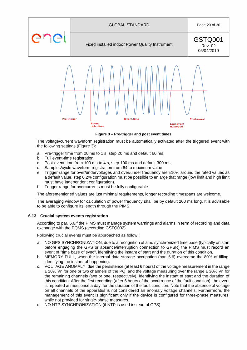
Figure 3 – Pre-trigger and post event times
The voltage/current waveform registration must be automatically activated after the triggered event with the following settings (Figure 3):
a. Pre-trigger time from 20 ms to 1 s, step 20 ms and default 60 ms; b. Full event-time registration; c. Post-event time from 100 ms to 4 s, step 100 ms and default 300 ms; d. Samples/cycle waveform registration from 64 to maximum value e. Trigger range for over/undervoltages and over/under frequency are ±10% around the rated values as
a default value, step 0.2% configuration must be possible to enlarge that range (low limit and high limit must have independent configuration).
f. Trigger range for overcurrents must be fully configurable.
The aforementioned values are just minimal requirements, longer recording timespans are welcome.
The averaging window for calculation of power frequency shall be by default 200 ms long. It is advisable to be able to configure its length through the PIMS.
6.13 Crucial system events registration
According to par. 6.6.f the PIMS must manage system warnings and alarms in term of recording and data exchange with the PQMS (according GSTQ002).
Following crucial events must be approached as follow:
a. NO GPS SYNCHRONIZATION, due to a recognition of a no synchronized time base (typically on start before engaging the GPS or absence/interruption connection to GPSR) the PIMS must record an event of "time base of sync", identifying the instant of start and the duration of this condition.
b. MEMORY FULL, when the internal data storage occupation (par. 6.6) overcome the 80% of filling, identifying the instant of happening.
c. VOLTAGE ANOMALY, due the persistence (at least 6 hours) of the voltage measurement in the range ± 10% Vn for one or two channels of the PQI and the voltage measuring over the range ± 30% Vn for the remaining channels (two or one, respectively). Identifying the instant of start and the duration of this condition. After the first recording (after 6 hours of the occurrence of the fault condition), the event is repeated at most once a day, for the duration of the fault condition. Note that the absence of voltage on all channels of the apparatus is not considered an anomaly voltage channels. Furthermore, the management of this event is significant only if the device is configured for three-phase measures, while not provided for single-phase measures.
d. NO NTP SYNCHRONIZATION (if NTP is used instead of GPS).

GLOBAL STANDARD Page 21 of 30
Fixed installed indoor Power Quality Instrument GSTQ001
Rev. 02 05/04/2019
7 PQI EXTENDED REQUIREMENTS
The requirements from this chapter must be respected just if expressely requested during the procurement process par. 10.2.
7.1 Power supply enhancement
A battery must be present to assure a continuity of the measurements at least for 30 minutes of interruption of any other power supply disturbance (UPS function).
7.2 Current input channels enhancement
The PQI shall arrange:
a. At least 6 terminals for measuring the three phase currents via current-to-voltage transducers. Connection will be provided by means of conductors having a cross-section up to 1.5 mm2 (AWG 16). Voltage range shall be at least 3 Vrms with a permanent overloading capacity up to +100%. Input impedance shall be higher than 1 MΩ. Measuring accuracy is not required above +20%.
b. With reference to the par. 6.4.2, additional 2 terminals must be added for neutral current measurement.
7.3 Other input and output channels enhancement
Input and output channels in Table 4 must be provided:
Table 4 – Output/Input channel charateristics
Type N° of channels Range Terminal blocks
Analogue outputs 4 4 ÷ 20 mA for conductors up to 2.5 mm2 (AWG 14).
Insulated digital outputs 1 24 ÷ 130 Vdc
for conductors up to 2.5 mm2 (AWG 14).
Insulated digital inputs 12 24 ÷ 130 Vdc
for conductors up to 2.5 mm2 (AWG 14).
Each analogue output channel shall be associated with any of the following internal variables through the PIMS:
c. RMS voltage. d. RMS current. e. Active power. f. Reactive power. g. Power frequency.
For powers the zero-level will be adjusted in the middle of the overall range (i.e. 12 mA).
For frequency the output current range (4 ÷ 20 mA) must be optimized according to Table 5:
Table 5 – Analog outputs current in case of power frequency
Power frequency [f] Analog outputs current [mA]
f < 45 Hz 4 mA
45 Hz ≤ f ≤ 48.75 Hz 1.0667f – 44
48.75 Hz < f < 51.25 Hz 3.2f – 148
51.25 Hz ≤ f ≤ 55 Hz 1.0667f – 38.6667
f > 55 Hz 20 mA
7.4 Expansion ports
The PQI must be equipped with at least 1 expansion slot, that will allow:

GLOBAL STANDARD Page 22 of 30
Fixed installed indoor Power Quality Instrument GSTQ001
Rev. 02 05/04/2019
a. The inclusion in the PQI of new accessories (particularly the M3G of par. 8.2), without the change of
the dimension of PQI types W and D; b. The inclusion in the PQI of new accessories (particularly the M3G of par. 8.2), without the violation of
rack standard dimension for PQI type R and avoiding to hide any embedded connector creating trouble in cabling;
c. The replication of all the port of the new accessories; d. The complete data exchange between new accessories and PQI; e. The power supply of new accessories.
7.5 Voltage dip monitoring according to Italian Regulation enhancement
The PQI must be fully compliant with the technical specification RSE 12004159, in order to be inserted in the Italian voltage dip monitoring survey promoted by regulation ARG/elt 198/11.
Particularly the voltage dip validation system described in RSEpaper must be implemented in the PQI, but can be disabled in PIMS configuration (it is enabled for default).
7.6 Energy measurement enhancement
The PQI must include:
a. active energy meter functionalities according to IEC 62053-22 Class 0.2S; b. reactive energy meter functionalities according to IEC 62053-23 Class 2;
The PQI has to measure energy with such levels of accuracy, but it is no requested to behave exactly as a commercial power revenue meter.
7.7 Mains signalling voltage enhancement
According to IEC 62586-1 all the requirements for the PQ parameter “mains signalling voltage” must be also respected.
7.8 Specific RTU functionalities according to Spanish requirements enhancement
In order to seamlessly integrate the PQI into Spanish substations, the PQI shall behave as a MODBUS RTU server according to ENDESA SNC021 local standard. This serial port may be provided natively or by means of a serial dongle.
The meter shall arrange a led emitter for either active or reactive power pulse metering. This functionality may also be provided by means of a dongle. This functionality may also be provided by means of a dongle or by direct Wh and VAr display on the front-panel.
7.9 IEC 61850 enhancement
The PQI shall arrange specific online measurements and fault recording capabilities (see GSTQ002 for detailed information).
7.10 Triggered events registration enhancement
Post-event time from 100 ms to 60 s, step 100 ms and default 300 ms has to be adopted instead what declared in the par. 6.12.
Moreover, acquisition of instantaneous waveforms for all voltage channels must be available. This function is aimed at storing the instantaneous samples of the monitorized voltages/currents in event condition to allow post-processing for fault location maintenance; even if the event impacts just a single voltage or current.
All available and under use voltage/current channels must be included. The function involves the acquisition of all the waveforms and the RMS values of the channels in synchronous mode in the PQDIF file for each voltage event on any channel. So, not only the event affected waveform must be shared, but all the available waveforms.

GLOBAL STANDARD Page 23 of 30
Fixed installed indoor Power Quality Instrument GSTQ001
Rev. 02 05/04/2019
As a default configuration, the acquisition must be enabled for events in the voltage channels L1, L2, L3 (for dips, swells and interruptions) and in the homopolar voltage channel L4 (for swells). The voltages L1, L2 and L3 can be stored phase-to-neutral (L1-N, L2-N, L3-N) or phase-to-phase (L1-L2, L2-L3, L3-L1) depending on the type of wiring selected in configuration as recorded at this time.
7.11 Trends registration enhancement
According to IEC 61000-4-30 and Table 6, the PQI must provide trend registration (data exchange between PQI and PQMS must be according GSTQ002).
All the configurations must be done in the PIMS.
Table 6 – Trends registration
PQ parameter Activable trends
Power frequency
10/12 cycles measurement (that is also the default) or multiples (just for the analog outputs), accuracy 0.01 Hz.
10 s measurement.
Aggregation from 10 minute to 2 hours (step 10 minute, default 10 minutes).
Magnitude of the supply voltage
Magnitude of current
10/12 cycles measurement (default for the analog outputs).
150/180 cycles aggregation measurement.
Aggregation from 10 minutes to 2 hours (step 10 minute, default 10 minutes).
Supply voltage unbalance
Current unbalance
10/12 cycles measurement (default for the analog outputs).
150/180 cycles aggregation measurement.
Aggregation from 10 minutes to 2 hours (step 10 minute, default 10 minutes).
Voltage/Current harmonics
10/12 cycles measurement (default for the analog outputs).
150/180 cycles aggregation measurement.
Aggregation from 10 minutes to 2 hours (step 10 minute, default 10 minutes).
Voltage/Current inter-harmonics
10/12 cycles measurement (default for the analog outputs).
150/180 cycles aggregation measurement.
Aggregation from 10 minutes to 2 hours (step 10 minute, default 10 minutes).
Under/over deviation
10/12 cycles measurement (default for the analog outputs).
150/180 cycles aggregation measurement.
Aggregation from 10 minutes to 2 hours (step 10 minute, default 10 minutes).
Flicker
10 minutes computation for Pst (default for the analog outputs).
2 hours computation for Plt (default for the analog outputs).
Aggregation according to IEC 61000-4-15.
GLOBAL STANDARD Page 24 of 30
Fixed installed indoor Power Quality Instrument GSTQ001
Rev. 02 05/04/2019
7.12 Configuration file enhancement
This function determines the sending of a file with the same name to each PQDIF file extension .CFG (instead of .PQD), containing all the configuration parameters of the device and the data contained in the PIMS.
The proposed format of this file is text/Json.
It is also required the presence of IMSI SIM, IMEI MODEM and IP ADDRESS MODEM fields for storing the information related to the comunication part and any other configuration setting available in the PIMS.
7.13 Communication enhancement
With reference to point 6.5.a, an 1gb ethernet optical port must be added in the rear, for data exchange with the PQMS or for local configuration.

GLOBAL STANDARD Page 25 of 30
Fixed installed indoor Power Quality Instrument GSTQ001
Rev. 02 05/04/2019
8 PQI ACCESSORIES
The accessories from this chapter must be included just if expressely requested during the procurement process par. 10.2.
8.1 Cables
The following cables must be included for PQI power supply and for connection of the trasducers:
a. Power supply cable, with first termination according to the PQI power supply input and the second according to country rules;
b. One cable for each input and output with both termination according to the specific terminal block.
8.2 Modem kit
The Modem kit is made by:
a. Modem 2G/3G (M3G) or higher configuration; b. Cellular antenna with magnetic mount, with 10 m RG-174U cable and termination with SMA male
connector.
The M3G must have the followings characteristics:
c. Compatible with cellular frequiences 2G (GSM850, GSM900, DCS1800, PCS1900) and 3G (B1-2100, B2-1900, B5-850, B8-900);
d. Installable in the PQI expansion slot (par. 6.5) or connected to an Ethernet or USB port. e. Compatible with SIM or mini SIM, according to ISO/IEC 7810; f. SMA female connector for external antenna; g. Compatible with CLI.
The antenna and cable in 8.2.b must assure >2.5dB gain and certified for indoor operation.
8.3 GPS kit
The GPS kit is made by:
a. GPS receiver (GPSR); b. 20 m cable for connection to PQI, both termination in RJ12; c. GPS antenna with magnetic mount and/or wall plugs, with 5 m cable, with L bracket; d. extra bracket for wall mounting.
The GPSR must be >20 channels parallel tracking GPS receiver designed to operate with the L1 frequency, Standard Position Service, Coarse Acquisition code.
GPSR must be able to synchronize up to 10 devices, like PQI or other devices that need accurate synchronization signal, according to IEC 61010-1, IEC 61000-6-5, CISPR 32, NMEA 0183. It must have at least 10 RJ12 connectors (Figure 2), each one providing:
e. RS422/485 serial connection (just TX+ TX- pins) with NMEA 0183 protocol; f. open-collector pulse-per-second (PPS+, PPS- pins) output synchronization signal; g. GPSR external power input (Vdc, GND pins).
The power supply input can be provided equally by each of the 10 devices connected to the receiver, without the need to assign to a single device the function of power source and exclude all other.
The power supply characteristics must be:
h. 9 ÷ 14 Vdc; i. <3 VA; j. 24 V MAX, 5 mA MAX of electrical range.
The 1PPS characteristics must be:
k. >0.5 s of signal duration;

GLOBAL STANDARD Page 26 of 30
Fixed installed indoor Power Quality Instrument GSTQ001
Rev. 02 05/04/2019
l. ±100 ns of signal precision; m. <24 V, <5 mA of electrical range.
The cable in 8.3.b must have the both terminations in RJ12 (Figure 2).
The antenna and cable in 8.3.c must assure >20dB gain and certified for outdoor operation, also in term of environmental/safety/EMC requirements.

GLOBAL STANDARD Page 27 of 30
Fixed installed indoor Power Quality Instrument GSTQ001
Rev. 02 05/04/2019
9 TESTING AND CERTIFICATIONS
According to IEC 62586-1 and IEC 62586-2 all the requirements from this chapter must be respected. Enel has the right to ask a prototipe for any kind of verification testing. That tests can be performed in the provider factory or laboratories, no cost participation by Enel.
9.1 Testing
Functional, environmental and safety type tests must be made according to IEC 62586-1.
Routine tests must be made according to IEC 62586-1.
Functional and uncertainty tests must be made according to IEC 62586-2.
9.2 IEC 61000-4-30 certification
The certificate of conformity to IEC 61000-4-30 must be provided.
The certificate must summarizes the results of a compliance report (based on compliance tests), that must be also provided; the compliance tests must be made according to IEC 62586-2.
The certificate and the report must be signed by a third party entity, qualified according to ISO/IEC 17025 and ISO/IEC 17065; however the final decision about the validity of the certification is made by Enel.
9.3 Certifications or self-certifications of calibration
A certificate or selfcertificate of calibration must be provided, it must be valid for the first 3 years from the delivery; so this document must certificate that no further calibration is needed for the first 3 years.
During this period the PQI must preserve its metrological qualities (included the IEC 61000-4-30 conformity).
9.4 Other certifications and self-certifications
About the compliance of all the requirements recalled in this GS, a certificate or selfcertificate must be provided.
Regional laws or standards may requires additional certifications or self-certifications.
Certifications and self-certifications must be made according to IEC 62586-1 and IEC 62586-2 (included the template adopted).
9.5 RSE certification
This certificate of conformity must be provided if the extended requirement in par. 7.5 is requested.
The Italian institution Ricerca sul Sistema Energetico SpA (RSE) is the only entity that can certificate the PQI according to this requirement.

GLOBAL STANDARD Page 28 of 30
Fixed installed indoor Power Quality Instrument GSTQ001
Rev. 02 05/04/2019
10 MISCELLANEOUS
This chapter include further requirement, recommendation and additional information.
10.1 Required documentation
The following documents (in pdf format) must be provided:
a. User’s manual; b. Maintenance manual; c. Quick installation and set-up guide; d. Administrator’s manual, for proper integration of PQI into communication and IT networks (this
document should describe any network service the PQI is supplying); e. Installation and one-wire diagrams in DWG/DXF formats; f. PQI data sheet with snapshots; g. All software need to PQI operation;
This documents must be made according to IEC 61010-1 and they must be approved by Enel.
A copy of these documentation must be accessible by the PIMS.
10.2 Clarification during procurement process
By summarizing, during the procurement process the following clarification will be provided to the supplier:
a. Choice between PQI-A-FI2-G, PQI-S-FI2-G and PQI-A-FI1-H (chap. 6); b. Cybersecurity requirements (chap. 6); c. Choice about enclosure (par. 6.1); d. Choice about power supply (par. 6.2); e. Extended requirement included (chap. 7); f. Accessories included (chap. 8); g. Language for embedded sw and documentations.
10.3 Amendement
Because of the earlier stage of some international standards used in this GS, Enel may derogate some prescriptions.
The provider must official ask the possible derogation during the procurement process.
10.4 PQI delivery form
PQI, accessories etc. must be included in a single box, with adeguate mechanical protection against vibrations and bumps; also the immunity to bad weather must be adeguate. These boxes will be included in a main box.
The main box must be compliant with the selected transportation way.
The main box must have a external and well visible sticker with:
a. PQI name; b. Trademark; c. CE mark (in EU); d. Product number and serial number; e. Number PQI included; f. Enel contract reference number.
Enel will provide all the detailed specification before the field delivery.

GLOBAL STANDARD Page 29 of 30
Fixed installed indoor Power Quality Instrument GSTQ001
Rev. 02 05/04/2019
10.5 Typical configuration
In order to facilitate the procurement process in each country, most typical devices and options have been listed. This list is not intended for limiting the available choices.
Table 7 – Most typical configurations.
Id no. Description Applied options
1 PQI type R Italy
6 - PQI-A-FI1-H. 6.1.a - Rack 19” mounting according to IEC 60297-3-100 (named type R); 6.2.a - 110 Vdc (+15%, -15%); 7.2.a - Current input channels enhancement; 7.3 - Other input and output channels enhancement; 7.4 - Expansion ports; 7.5 - Voltage dip monitoring according to Italian Regulation enhancement; 7.6 - Energy measurement enhancement; 7.10 - Triggered events registration enhancement; 7.11 - Trends registration enhancement; 7.12 - Configuration file enhancement.
2 PQI type R Spain
6 - PQI-A-FI2-G; 6.1.a - Rack 19” mounting according to IEC 60297-3-100 (named type R); 6.2.d - 125 Vdc (+15%,-15%); 7.6 - Energy measurement enhancement; 7.8 - Specific RTU functionalities according to Spanish requirements enhancement
3 PQI type D Spain
6 - PQI-A-FI2-G; 6.1.c - Top hat rail 35 × 15 according to IEC 60715 (named type D); 6.2.d - 125 Vdc (+15%,-15%); 7.6 - Energy measurement enhancement; 7.8 - Specific RTU functionalities according to Spanish requirements enhancement
4 PQI type R Romania
6 - PQI-A-FI1-H. 6.1.c - Rack 19” mounting according to IEC 60297-3-100 (named type R); 6.2.a - 110 Vdc (+15%, -15%); 7.2.a - Current input channels enhancement; 7.4 - Expansion ports; 7.10 - Triggered events registration enhancement; 7.11 - Trends registration enhancement; 7.12 - Configuration file enhancement.
5 PQI type B Chile
6 - PQI-A-FI2-G; 6.1.d - Half Rack 19” mounting according to IEC 60297-3-100 (named type B), that is simple a custom design where 2 devices behave as a single rack device (see figure 1) 6.2.c - 125 Vdc (+30%,-30%); 7.6 - Energy measurement enhancement.
6 PQI type W Brazil
6 - PQI-A-FI2-G; 6.1.b - Wall mounting with plugs (named type W); 6.2.d - 125 Vdc (+15%,-15%); - 125 Vdc (+30%,-30%); 6.2.i - 48 Vdc (+15%, -15%);

GLOBAL STANDARD Page 30 of 30
Fixed installed indoor Power Quality Instrument GSTQ001
Rev. 02 05/04/2019
7 PQI type P Colombia
6 - PQI-A-FI2-G; 6.1.e - Panel mounting (named type P) with dimension 28 cm (Width) ×19 cm (Height) × 20 cm (Depth). 6.2.j - DC or AC supplies through the same power terminals within the range 120 Vdc (+ 15%, -15%) and 120 Vac (+ 15%, -15%) 60 Hz as rated frequency. 7.2.b - With reference to the par. 6.4.2, additional 2 terminals must be added for neutral current measurement. 7.6 - Energy measurement enhancement; 7.9 - IEC 61850 enhancement; 7.10 - Triggered events registration enhancement.