ميحرلا نمحرلا الله مسب - saadawi1 the voltage distribution of an insulator of 3...
TRANSCRIPT

بسم هللا الرحمن الرحيم
رب اشرح لى صدرى ويسر لى أمر
واحلل عقدة من لسانى يفقهوا قولى
صدق هللا العظيم

Chapter 11
pp. 370-389
Overhead Line Insulators part 2

Potential Distribution over a String of Suspension Insulators p. 376
• The voltage across the discs of the string is not uniformly distributed. This is because of the capacitances formed between the metal parts of the insulators and tower structure.
• These capacitances could be made negligibly small by increasing the distance between the insulators and the tower structure which requires larger lengths bigger size of the towers and hence it becomes uneconomical.
4/17/2013 Prof. Dr. Magdi El-Saadawi 3

4/17/2013 Prof. Dr. Magdi El-Saadawi 4

4/17/2013 5Prof. Dr. Magdi El-Saadawi

• In practice the insulators are not very far from the tower structure and hence these capacitances affect the voltage distribution across the string
4/17/2013 Prof. Dr. Magdi El-Saadawi 6
• Since the insulator discs are identical, each disc is represented by its mutual capacity C
• A shunt capacitance C1 is the capacitance of metal part of the insulator disc to the tower structure (ground). So that C1 = m C• Where m is the ratio between the capacitance to
ground to the mutual (unit) capacitance

• Let V be the operating voltage and V1,V2,V3
and V4 the voltage drops across the units starting from cross towards the power conductor.
V = V1 + V2 + V3 + V4
• The objective is to find out the voltage across each disc as a multiple of the operating voltage and to compare the voltage across each unit.
4/17/2013 Prof. Dr. Magdi El-Saadawi 7

C : capacitance of each insulator unit.
C1 = m C : capacitance to ground
is the capacitance of metal part of the insulator
unit to the tower (m<1).
V1, V2, V3 the voltage across each unit starting from
the cross arm towards the power conductor.
V = V1 + V2 +V3 Line voltage
4/17/2013 8Prof. Dr. Magdi El-Saadawi

At point P:
I2 = I1 +Ic1
ωC.V2 = ωC.V1 + ωmC.V1
V2 = (1+m).V1
At Point Q:
I3 = I2 + Ic2
ωC.V3 = ωC.V2 + ωmC.(V1+V2)
V3=m.V1 +(1+m).V2
=(m +(1+m)2).V1
V3 = (1+3m +m2).V1
4/17/2013 9Prof. Dr. Magdi El-Saadawi

The voltage across the units cam also given by:
n= 1 V2 = (1+ m). V1
n=2 V3 = (1+ 3 m +m2). V1
n=3 V4 = V3.(1+ 6 m +5 m2 + m3). V1
n=4 V5= V4.(1+ 10 m + 15 m2 + 7m3 + m4 ). V1
4/17/2013 10Prof. Dr. Magdi El-Saadawi

To Find the voltage across each disk
• For 3 disc string:
• V = V1 + V2 + V3
• V = V1 + V1 (1+ m) + V3 (1+ 3m + m2)
• V = V1 (3 + 4 m + m2)
• Then you can find V1 , V2 and V3
• WhereV: Voltage across the insulator string, (phase Volt)
4/17/2013 Prof. Dr. Magdi El-Saadawi 11
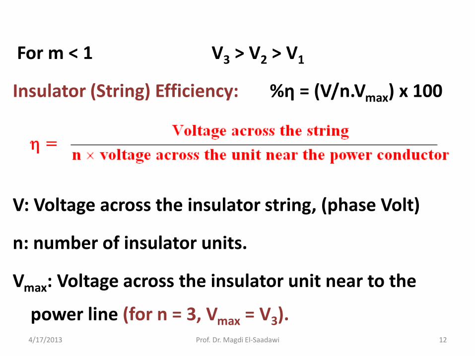
For m < 1 V3 > V2 > V1
Insulator (String) Efficiency: %η = (V/n.Vmax) x 100
V: Voltage across the insulator string, (phase Volt)
n: number of insulator units.
Vmax: Voltage across the insulator unit near to the
power line (for n = 3, Vmax = V3).4/17/2013 12Prof. Dr. Magdi El-Saadawi

Example (1)
Find the voltage distribution of an insulator of
3 units, if the maximum voltage of each unit
is 17 kV, and the capacitance to ground is
20% of unit capacitance, also find the
insulator efficiency.
4/17/2013 13Prof. Dr. Magdi El-Saadawi

V3 = 17 kV, m=20% = 0.2
V2 = (1+m).V1 = 1.2 V1
V3 = (1+ 3 m +m2 ). V1 =1.64 V1
V1 = 17/1.64 = 10.36 kV
V2 = 1.2x10.36 = 12.43 kV
V= V1 + V2 + V3 = 39.8 kV
Insulator efficiency = (39.8/3x17)x100=78.03%
4/17/2013 14Prof. Dr. Magdi El-Saadawi

In general, voltage across the units can given by:
Vn+1 = Vn.(1+m) + (V1+V2+……+ Vn-1).m
n= 1 V2 = (1+m). V1
n=2 V3 = V2.(1+m) + V1.m
n=3 V4 = V3.(1+m) + (V1 +V2).m
n=4 V5= V4.(1+m) + (V1 + V2 +V3).m
4/17/2013 15Prof. Dr. Magdi El-Saadawi
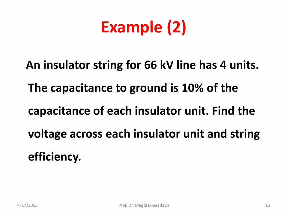
Example (2)
An insulator string for 66 kV line has 4 units.
The capacitance to ground is 10% of the
capacitance of each insulator unit. Find the
voltage across each insulator unit and string
efficiency.
4/17/2013 16Prof. Dr. Magdi El-Saadawi

V2 = (1+m). V1 = 1.1 V1
V3 = V2.(1+m) + V1.m = 1.31 V1
V4 = V3.(1+m) + (V1 +V2).m =1.651 V1
V1 +V2 +V3 +V4 = = 38.1 kV
V1 (1+1.1 +1.31+1.651)=38.1
V1=7.53 kV, V2= 8.28 kV, V3=9.86 kV, V4= 12.43 kV
String efficiency = (38.1/4x12.43)x100=76.6%
4/17/2013 17Prof. Dr. Magdi El-Saadawi

Improvement of String EfficiencyMethods of Equalizing Potential (p.386)
1- Reducing the ground capacitance relative to the
capacitance of insulator unit (reduce m where m = c1/c ):
This can be done by increasing the length of cross arm and
hence taller supporting tower which uneconomical.
4/17/2013 18Prof. Dr. Magdi El-Saadawi

Improvement of String Efficiency
2- Grading of insulator units: It can be seen that the
unequal distribution of voltage is due to the leakage current
from the insulator pin to the tower structure. The solution is
to use insulator units with different capacitances.
This requires that unit nearest the cross arm should have
minimum capacitance (maximum Xc) and the capacitance
should increase as we go towards the power line.
4/17/2013 19Prof. Dr. Magdi El-Saadawi

This means that in order to carry out unit grading,
units of different types are required. This requires
large stocks of different units which is uneconomical
and impractical.
4/17/2013 20Prof. Dr. Magdi El-Saadawi

3- Static Shielding (Guard Ring): ( الحماية حلقة )
This method uses a large metal ring surrounding the bottom
insulator unit and connected to the line. This ring is called a
grading or guard ring which gives a capacitance which will
cancel the charging current of ground capacitance.
Improvement of String Efficiency
4/17/2013 21Prof. Dr. Magdi El-Saadawi

Guard ring serves two purposes:
- Equalizing the voltage drop across each insulatorunit.
- protects the insulator against flash over.
4/17/2013 22Prof. Dr. Magdi El-Saadawi

4/17/2013 Prof. Dr. Magdi El-Saadawi 23
pp. 389

4/17/2013 24Prof. Dr. Magdi El-Saadawi

4/17/2013 25Prof. Dr. Magdi El-Saadawi

4/17/2013 26Prof. Dr. Magdi El-Saadawi

4/17/2013 27Prof. Dr. Magdi El-Saadawi

4/17/2013 28Prof. Dr. Magdi El-Saadawi

Example (3)
A 3-unit insulator string with guard ring. The
capacitance to ground and to guard ring are
25 % and 10 % of the capacitance of each
unit. Determine the voltage distribution and
string efficiency.
4/17/2013 29Prof. Dr. Magdi El-Saadawi
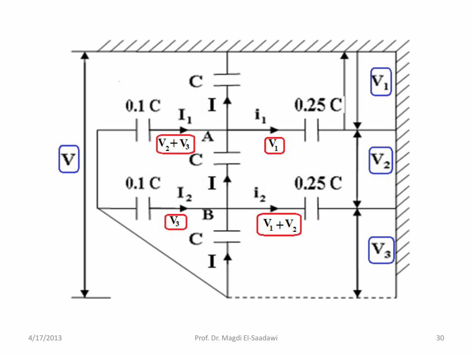
4/17/2013 Prof. Dr. Magdi El-Saadawi 30

At point A:
I1 + Iy = Ix + i1
0.1ωC.(V2+V3) + ωC.V2
= ωC.V1 + 0.25 ωC.V1
1.25 V1 -1.1 V2 -0.1 V3 =0.0
At point B:
I2 + Iz = Iy + i2
0.1ωC.V3 + ωC.V3
= ωC.V2 + 0.25ωC.(V1+V2)
0.25 V1 + 1.25 V2 -1.1V3 =0.0
4/17/2013 31Prof. Dr. Magdi El-Saadawi

Also: V1 + V2 + V3 = V
Solve, to get:
V1= 0.295V, V2 = 0.2985V, V3 = 0.406V
η = V/(3x0.406V)x100= 82.1 %
Find the voltage distribution and insulator
efficiency without a guard ring.
4/17/2013 32Prof. Dr. Magdi El-Saadawi