* tip company consent order h
TRANSCRIPT

UNITED STATES ENVIRONMENTAL PROTECTION AGENCYREGION VII
726 MINNESOTA AVENUE KANSAS CITY, KANSAS 66101
£
IN THE MATTER OF
E.I. DuPont de Nemours and Company
Respondent
Proceedings under Sections 104 and 122 of the Comprehensive Environmental Response, Compensation and Liability Act of 1980, as amended by the Superfund Amendments and Reauthorization Act of 1986,42 U.S.C. §§ 9604 and 9622.
2-- isej «thv
CONSENT ORDER
£ K L \* tip
^ HDocket No. VII-88-F0009
PRELIMINARY STATEMENT
1. This Consent Order is entered into by the
United States Environmental Protection Agency, Region VII
(EPA) and E.I. DuPont de Nemours and Company ("DuPont"
or "Respondent") pursuant to Sections 104 and 122 of the
Comprehensive Environmental Response, Compensation, and
Liability Act of 1980, as amended by the Superfund Amendments
and Reauthorization Act of 1986 (CERCLA), 42 U.S.C. §§ 9604
and 9622.
2. Pursuant to Section 104 of CERCLA, 42 U.S.C.
§ 9604, whenever a hazardous substance is released or there
is a substantial threat of a release of a hazardous substance
I11HIHI115159
2
into the environment, the President is authorized to take
removal or remedial action and any other response measure
including actions described in Section 104(b), 42 U.S.C.
9604, consistent with the National Contingency Plan which
the President deems necessary to protect the public health
or welfare or the environment. When the President determines
that such action will be done properly and promptly by the
owner or operator of the facility or by any other responsible
party, the President may allow such person to carry out the
action, conduct the remedial investigation, or conduct the
feasibility study in accordance with Section 122 of CERCLA,
42 U.S.C. § 9622. Furthermore, no remedial investigation or
feasibility study (RI/FS) shall be authorized except upon a
determination by the President that the party is qualified to
•conduct the RI/FS and only if the President contracts with or
arranges for a qualified person to assist the President in
overseeing and reviewing the conduct of such RI/FS and if the
responsible party agrees to reimburse the Fund for any costs
incurred by the President under, or in connection with, the
oversight contract or arrangement.
3. Pursuant to Section 122(d)(3) of CERCLA, 42
U.S.C. § 9622(d)(3), whenever the President enters into an
agreement under this section with any potentially responsible
party with respect to action under Section 104(b), 42 U.S.C.
9604, the President shall issue an order or enter into a

3
decree setting forth the obligations of such party. The
United States District Court for the district in which the
release or threatened release occurs may enforce such order
or decree.
4. The authority vested in the President pursuant
to the above-cited provisions of CERCLA was delegated to the
Administrator of the EPA by Executive Order 12580, 52 Fed.
Reg., 2923, dated January 29, 1987, and was further delegated
to the Regional Administrators by EPA Delegation No. 14-14-C,
dated February 27, 1987.
STATEMENT OF PURPOSE
5. In entering into this Consent Order, the mutual
objectives of EPA and DuPont are: (1) to determine fully the
nature and extent of the threat to the public health or
welfare or the environment caused by the release or threatened
release of hazardous' substances, pollutants or contaminants
from the DuPont Landfill Cell (Remedial Investigation), and
(2) to evaluate alternatives for the appropriate extent of
remedial action to prevent or mitigate the migration or the
release or threatened release of hazardous substances, pol
lutants, or contaminants from the wifcwr DuPont Landfill Cell
(Feasibility Study). The activities conducted pursuant to
this Consent Order are subject to approval by EPA and shall
be consistent with the National Contingency Plan, 40 C.F.R.
Part 300.
4
FINDINGS OF FACT
6. EPA has determined and DuPont agrees that all
findings of fact necessary for the issuance of this Consent
Order pursuant to Sections 104 and 122.of CERCLA have been
made and are outlined below.
7. The DuPont Industrial Waste Cell ("Cell" or
"Facility") is located at the Lawrence Todtz Farm Site (Site).
The Site is located at SEl/4, SWl/4, SW1/4, Section 29,
Township 81 North, Range 6 East, of the 5th Principal Meridian,
Clinton County, about one and one-quarter miles west of
Camanche, Iowa. The Lawrence Todtz Farm site was added to
the National Priority List (NPL) in June of 1986.
8. The Respondent E.I. DuPont de Nemours and
Company ("DuPont" or "Respondent") is a Delaware corporation
which operated a plant in Clinton, Iowa for the manufacture
of cellophane until about 1975.
9. In the late 1960's, Lawrence Todtz leased a
former gravel pit area to Donald Null for use as a municipal
landfill for the City of Camanche, Iowa. In about 1971, the
McManus Brothers (Robert and Donald) took over operation of
the landfill. The McManus Brothers had a written contract
with Lawrence Todtz. . ...
10. DuPont, pursuant to an oral agreement with the
McManus Brothers, had a separate industrial landfill cell
constructed in the northwest corner of the former gravel pit
5
area for the disposal of waste from the cellophane plant in
Clinton, Iowa and used the cell until about 1975.
11. The DuPont Industrial Waste Cell is that portion
of the Todtz property that is the facility subject to this
Consent Order. The DuPont Industrial Waste Cell was reportedly
about 2.5 acres with a clay liner overlain with a polyethylene
membrane. DuPont disposed of about 4,300 tons of waste from
the cellophane plant at the landfill cell between about 1972
and 1975. A clay cap was installed in about 1975.
12. Investigations of the site were conducted by
the U.S. EPA Field Investigation Team (FIT) contractors in
August 1980 and August 1985.
13. During the period from about August 1986 to
August 1987, the U.S. EPA REM II team conducted further
investigation of the site which included the installation of
ground water monitoring wells and multimedia sampling and
analysis. Groundwater samples taken from monitoring wells
downgradient from the industrial cell have shown the presence
of levels as high as 3,600 ug/1 for carbon disulfide, 400
ug/l for lead, 8,800 ug/1 for toluene, 97,000 ug/1 for tetra-
hydrafuran, 1,000 ug/1 for 4-methylphenol and 1.10 ug/1 for
mercury. These compounds are among those DuPont reported
were used at the Clinton cellophane plant.
14. Exposure to carbon disulfide may adversely
affect the central nervous system. Neuritis and visual

6
disturbance are the most common early changes observed.
Sensory changes are often followed by gradual loss of strength.
Mental symptoms vary from simply excitation or depression to
mental deterioration and the development of a Parkinson-like
disease. Carbon disulfide has been found to bind to blood
hemoglobin and other plasma proteins and adversely affects
kidney and liver function as well as zinc metabolism.
15. Tetrahydrofuran mainly targets the respiratory
and central nervous systems. Irritation of the skin and
mucus membranes, including the eyes, nose, and upper respiratory
tract, are the predominant effects observed as a result of
low concentration exposures. Nausea, dizziness, and headache
may accompany these symptoms.
16. Potential health effects resulting from exposure
to methyl phenols include intense burning of the mouth and
throat followed by marked abdominal pain. Collapse, manifestedf
by muscular weakness and unconsciousness, may occur if these
compounds are ingested in high amounts. Increased respiration
and body temperature fluctuations may precede respiratory
failure.
17. Exposure to heavy metals such as lead, arsenic,
and mercury may result in a variety of deleterious effects
affecting the GI tract and central nervous system, depending
on the compound. Impaired kidney function may also occur.

7
Symptoms of insomnia, lassitude, weight loss, and abdominal
irritation may occur as a result of acute exposure.
18. A sand gravel terrace associated with glacial
outwash activity forms the natural uppermost aquifer around
the Site. Domestic wells are located downgradient of the
Site within one-half mile and are primary potential receptors
for contaminated ground water. Surface water bodies in the
vicinity of the Site which are primary potential receptors
for contaminated run-off and/or recharge are the north and
south ponds, Willow Lake, and Bandixen Lake. Secondary
potential receptors include other downgradient lakes and the
federally owned and managed Upper Mississippi River Fish and
Wildlife refuge located less than one mile from the Site.
19. By letter dated August 4, 1987, EPA notified
DuPont of EPA's intention to conduct a Remedial Investigation
and Feasibility Study to respond to releases and threatenedf
releases of hazardous substances at the site if such actions
were not taken by DuPont or some other person. EPA offered
DuPont the opportunity to undertake these response actions
upon providing assurances that the response actions would be
properly conducted, such as by entering into an administrative
consent order. A meeting was held between EPA and DuPont on
September 10, 1987, to discuss the results of the REM II
investigations of the site including the groundwater sampling
conducted during the preceding several months and the need

8
for and scope of an RI/FS for the site. By letter dated
September 24, 1987, DuPont confirmed its agreement to conduct
an RI/FS for the DuPont Industrial Waste Cell pursuant to an
administrative consent order. DuPont has retained an engineering
firm with expertise in hazardous waste site investigations and
remediation.
CONCLUSIONS OF LAW
20. The DuPont Industrial Landfill cell is a
"facility" as defined in Section 101(9) of CERCLA, 42 U.S.C.
§ 9601(9).
21. The Respondent is a "person" as defined in
Section 101(21) of CERCLA, 42 U.S.C. § 9601(21).
22. Some of the wastes disposed of at the facility,
including but not limited to, lead, mercury, tetrahydrofuran,
toluene, 4-methylphenol (paracresol) and carbon disulfide are
"hazardous substances" as defined in Section 101(14) off
CERCLA, 42 U.S.C. § 9601(14).
23. Respondent was the generator of the hazardous .
substances, pursuant to Section 107(a)(3) of CERCLA, 42
U.S.C. § 9607(a)(3).
24. The actions required by this Order are consistent
with the National Contingency Plan, 40 C.F.R. Part 300, and
are necessary to protect the public health and welfare and
the environment.
- 9 -
25. The past, present, or potential migration of
hazardous substances from the facility constitute an actual
and/or threatened "release" as defined in Section 101(22) of
CERCLA, 42 U.S.C. § 9601(22).
DETERMINATIONS
26. The Regional Administrator, EPA Region VII,
has determined that the release and threatened release of
hazardous substances into the environment from the landfill
cell requires the response actions set forth hereafter; that
DuPont is qualified to conduct the RI/FS and will properly
and promptly perform such response actions; that the actions
required by this Agreement are necessary to protect the public
health, welfare or the environment; and that if conducted as
set forth herein, such actions will be consistent with the
National Contingency Plan, 40 C.F.R. Part 300.
27. The Respondent consents to ahd will not contest
EPA's jurisdiction regarding this Consent Order. The Respondent
agrees to undertake all actions required of it by the terms
and conditions of this Consent Order.
CONSENT ORDER
28. The Respondent shall commence work and thereafter
implement the tasks detailed in the Remedial Investigation
and Feasibility Study Work Plan (RI/FS Work Plan) which is
attached hereto and incorporated herein as Attachment 1
including the statement of scope, contingency triggers and
10
schedule which is attached hereto and incorporated herein as
Attachment 2. The RI/FS Work Plan has been approved by EPA.
The work shall be conducted in accordance with the EPA Remedial
Investigation and Feasibility Study gui.dance documents and
with the standards and specifications contained in the RI/FS
Work Plan, and the schedule contained in Attachment 2\
29. The Respondent shall provide preliminary and
final reports to EPA according to the schedule contained in
Attachment 2.
30. After EPA reviews the preliminary and final
reports, EPA shall notify the Respondent in writing, of EPA's
approval or disapproval of these reports or any part thereof.
After review of any report, EPA may also notify the Respondent
in writing of EPA disapproval of Respondent's implementation
of the approved Work Plan.
31. In the event of any EPA disapproval of a
submitted report or disapproval of Respondent's implementation
of the approved Work Plan, the EPA shall send Respondent a
Notice of Disapproval delineating the deficiencies, recommending
revisions to the reports and additional or modified work to cure
the deficiencies in the work agreed to and setting a schedule for
response by Respondent.
32. Thereafter, the Respondent shall amend and
submit to EPA revised reports and perform such additional or
11
modified work to cure the deficiencies in the reports or work
agreed to in accordance with the EPA recommendations.
33. In the event of subsequent disapproval of such
revised reports or additional or modified work, the EPA
retains the right to amend such reports, perform additional
or modified work, conduct the complete RI/FS pursuant to its
authority under CERCLA, and/or undertake any judicial or
other remedy available to it by law.
34. EPA may determine that additional tasks,
including remedial investigatory work and/or engineering
evaluation, are necessary as part of the RI/FS in addition to
EPA approved Work Plan tasks including reports, which have
been completed pursuant to this Order and may request Respondent
to implement any such additional tasks as part of the RI/FS.
35. The Respondent shall implement any additional
tasks in addition to the tasks detailed in the EPA approved
Work Plan as are mutually agreed upon by EPA and DuPont. The
additional work shall be completed in accordance with the
standards, specifications and scheduled determined or approved
by EPA.
36. All work performed pursuant to this Consent
Order shall be under the direction and supervision of a
professional engineer or geologist with expertise in hazardous
waste site investigations and remediation. Within 30 days of
the effective date of this Consent Order, Respondent shall
notify EPA in writing of the name, title, and qualifications
12
of the engineer or geologist, and of any contractors or
subcontractors and their personnel to be used in carrying out
the terras of this Consent Order.
QUALITY ASSURANCE
37. All samples analyzed pursuant to this'Agreement
shall be analyzed by a laboratory which participates in a
quality assurance/quality control program equivalent to that
specified in the document entitled "USEPA Contract Laboratory
Program Statement of Work for Organic Analysis" (September 1984)
(hereinafter "Contract Lab Statement of Work").
38. All sample collection and analysis shall be
performed in compliance with EPA-approved methods, including
timing of analyses, documentation of sample collection,
handling and analysis, as described in the following documents:
a. "NEIC Manual for Groundwater/Subsurface
Investigations at Hazardous Waste Sites," Document No.
EPA/330/9-81-002; and
b. Cqntract Lab Statement of Work.
39. Laboratory deliverables as specified in the
Contract Lab Statement of Work shall be submitted to EPA for
all analytical work performed pursuant to this Order. Any
deviations from the procedures and methods set forth in these
documents must be approved in writing by EPA prior to use.
40. Respondent shall use the quality assurance,
quality control, and chain of custody procedures specified in
the Quality Assurance Project Plan for all sample collection and
analysis performed pursuant to this Order.
13
41. All contracts for field work and laboratory
analysis shall provide that EPA representatives are allowed
access, for auditing and evaluation purposes, at reasonable
times upon reasonable request, to all laboratories and personnel
utilized by Respondent for sample collection and analysis and
other field work. Upon request by EPA, the laboratories
shall perform analysis of a reasonable number of known samples
provided by EPA to demonstrate the quality of the analytical
da ta.
REPORTING
42. Beginning with the month following the effective
date of this order, Respondent shall provide EPA with written
progress reports for each month, by the tenth day of the
following month. At a minimum, these progress reports shall:
(1) describe the actions, progress, and status of projects
which have been taken toward achieving compliance with this
Consent Order; (2) describe all plans and activities completed
during the past month, as well as the actions which are
scheduled for the next month; (3) identify any requirements
under this Order that were not completed as provided and any
problem areas and anticipated problem areas in complying with
this Consent Order; and (4) include the results of sampling
and tests and other data generated pursuant to the Work
Plan(s ).
14
ACCESS
43. EPA and/or any EPA representative, including
EPA contractors, are authorized to enter and freely move
about all property at the Facility for the purposes of, inter
alia: interviewing Facility personnel and contractors;
inspecting records, operating logs, and contracts related to
the Facility; reviewing the progress of the Respondent in
carrying out the terms of this Order;•conducting such sampling
and tests as EPA or its representative deem necessary; using
a camera, sound recording, or other documentary type equipment;
and verifying the reports and data submitted to EPA by the
Respondent. The Respondent shall permit such persons to
inspect and copy all records, files, photographs, documents,
and other writings, including all sampling and monitoring,
data, that pertain to work undertaken pursuant to this
paragraph, and shall comply with all approved health and
safety plans.
44. To the extent that work required by the Work
Plan must be done on property not owned or controlled by
Respondent, Respondent will use its best efforts to obtain
site access agreements from the present owner(s) of such
property within thirty (30) days of the effective date of
this Order. Any such access agreement shall be incorporated
by reference into this Order. In the event that agreements
for site access are not obtained within thirty (30) days of

15
the effective date of this Consent Order, Respondent shall
notify EPA regarding both the lack of and its failure to
obtain such agreements within seven (7) days thereafter. In
the event that EPA obtains access for*Respondent, all costs incurred by the EPA shall be reimbursed by Respondent and
Respondent shall undertake EPA approved work on such property. Nothing in this section limits or otherwise affects EPA's
right of access and entry pursuant to applicable law, including
RCRA and CERCLA.
SAMPLING AND DATA/DOCUMENT AVAILABILITY
45. Respondent shall make available to EPA all
results of sampling, tests, or other data generated by or on
its behalf with respect to the implementation of this Consent
Order. Respondent shall submit these results in the progress
reports described in the "Reporting" Section of this Consent
Order.
46. Respondent shall notify EPA fat least seven (7)
days before conducting any well drilling, installation of
equipment, or sampling. At the request of EPA, Respondent
shall provide or. allow EPA or its authorized representative
to take split samples of all samples collected by Respondent
pursuant to this Consent Order. Similarly, at the request of
Resondent, EPA shall allow Respondent or its authorized
representatives to take split or duplicate samples of all
samples collected by EPA under this Consent Order. EPA shall
notify Respondent at least seven (7) days before conducting
any sampling under this Consent Order.
47. All information and data shall be available to
the public except to the extent that it is confidential
business information. Respondent may, if it desires, assert
a business confidentiality claim covering part or all of the
information submitted to, or reviewed by, EPA. Such a claim
may be made by placing on (or attaching to) the information,
at the time of its submittal to, or review by, EPA, a cover
sheet, stamped or printed legend, or other suitable form of
notice employing language such as "trade secret," "proprietary,"
or "company confidential." Allegedly confidential portions
of otherwise non-confidential documents should be clearly
identified and may be submitted separately to facilitate
identification and handling by EPA. If confidential treatment
is sought only until a certain date or until the occurrence
of a certain event, the request should so sitate. Analytical
data shall not be claimed as confidential by the Respondent.
Information submitted for which a claim of confidentiality is
made will be treated according to the procedures specified in
40 C.F.R. Part 2, Subpart B and Section 104(e)(7) of CERCLA,
42 U.S.C. 6904(e)(7). If no such claim is made when information
is received by EPA, the information may be made available to the
public without further notice.
17
RECORD PRESERVATION
48. Respondent agrees that it shall preserve
during the pendency of this Consent Order and for a minimum
of six (6) years after its termination, all records and
documents in its possession or in the possession of its
divisions, employees, agents or consultants or contractors
which relate in any way to this Consent Order or to hazardous
waste management and disposal at the Facility. At the
conclusion of six (6) years, Responondent shall then make
such records available to EPA for inspection or EPA’s retention
or shall provide copies of any such records to EPA.
the effective date of this Order or of retaining or employing an
agent, consultant or contractor, whichever comes first,
writing within 15 days, with its agents, consultants and/or
contractors whereby its agents, consultants and/or contractors
will be required to maintain and preserve during the pendency
of this Order and for a minimum of six years after its
termination, all records and documents within their respective
possession which relate in any way to this Order or to
hazardous waste management and disposal at the facility.
PROJECT COORDINATOR
50. On or before the effective date of this Consent
Order, EPA and Respondent shall each designate a Project
49. Respondent further agrees that within 5 days of
Respondent will enter .into an agreement, to be confirmed in
18
Coordinator. Each Project Coordinator shall be responsible
for overseeing the implementation of this Consent Order. The
EPA Project Coordinator will be EPA’s designated representative.
To the maximum extent possible, all communications between
Respondent and EPA, and all documents, reports, approvals,
and other correspondence concerning the activities performed
pursuant to the terms and conditions of this Consent Order,
shall be directed through the Project Coordinators. The
parties agree to provide at least seven (7) days written
notice prior to changing Project Coordinators. The absence
of the EPA Project Coordinator from the Facility shall not be
cause.for the stoppage of work.
NOTIFICATION
51. Unless otherwise specified, reports, notice or
other submissions required under this Consent Order shall be in
writing and shall be sent to:
Nancy Johnson, P.E.Regional Project Manager U.S. EPA, Region VII 726 Minnesota Avenue Kansas City, Kansas 66101
REIMBURSEMENT OF
Alan EglerEngineering DepartmentE.I. DuPont-de Nemours & CompanyWilmington, Delaware 19898
OVERSIGHT COSTS
52. Beginning from the end of 1988 fiscal year,
EPA shall submit to the Respondent an accounting and an
explanation of all oversight costs incurred with respect to
this Order during the previous fiscal year. Within fourteen
(14) days of receipt of such accounting, Respondent may
19
request the information used or relied upon to prepare the
accounting, and such information shall be made available to
Respondents for inspection and/or copying. Within sixty
(60) calendar days of receipt of each such initial accounting,
or of the supplemental information, whichever is later, the
Respondents shall remit a check to the U.S. EPA for the full
amount of those costs, unless the Respondents object that all
or a portion of the costs are or were not consistent with the
NCP or not actually incurred or not properly allocable to
this Consent Order. Any such portion of the costs objected
to by the Respondents shall be resolved pursuant to the
Dispute Resolution provisions of this Consent Order.
53. Payments to EPA shall be made to the order of
the Hazardous Substance Response Fund, and shall be forwarded
to the U.S. Environmental Protection Agency, Superfund Accounting,
P.0. Box 371003M, Pittsburgh, Pennsylvania 15251, ATTN:
Collection Officer for Superfund. A copy of the check and
transmittal letter should be sent to the ET)A contact specified
herein.
DELAY IN PERFORMANCE/STIPULATED PENALTIES
54. Unless EPA determines that the delay is attribu
table to a force majeure as defined in the Section entitled
"Force Majeure and Excusable Delay," for each period of time
as set forth below that the Respondent fails to submit the
following reports at the times required pursuant to this
Consent Order, Respondent shall pay the sums set forth below
as stipulated penalties. Stipulated penalties shall accrue
for failure to submit the preliminary agency review draft or
a final public review draft of any RI report or any FS report
at the time required pursuant to this Consent Order: $2,000
for the first week of delay or part thereof and $5,000 for
each day of delay after the first week. The schedule of times
for submission of the aforesaid reports are set out in
Attachment 2.
55. Any stipulated penalties paid pursuant to this
Consent Order shall be payable within twenty one (21) days
after Respondent's receipt of written demand by EPA, shall be
paid by certified or cashier's check made payable to the
Hazardous Substance Response Fund, and shall be remitted to:
EPA-SuperfundP.0. Box 371003MPittsburgh, Pennsylvania 1525.1
I*A letter describing the basis for the penalties shall accompany
the check. Copies of the transmittal of payment shall be
sent to the EPA contact specified herein.
56. The stipulated penalties set forth in this
Section do not preclude EPA from pursuing any other remedies
or sanctions which may be available to EPA by reason of -
Respondent's failure to comply with any of the requirements
21
of this Consent Order, nor shall payment of said penalties
relieve Respondent of the responsibility to comply with this
Consent Order. If the Respondent fails to pay stipulated
penalties, the EPA may institute proceedings to collect the
penalties.
57. Should Respondent fail to comply with' a time
requirement of any tasks required by this Consent Order, the
period of noncompliance shall terminate upon Respondent's
performance of said requirement.
58. If Respondent disputes the basis for imposition
of stipulated penalties, the issue shall be resolved under
the Dispute Resolution procedures of this Consent Order.-
The question of whether and in what amount Respondent shall
be liable for penalties which occurred prior to and during
the period of dispute shall be resolved by the Dispute
Resolution decision maker as part of that original dispute
fregarding the basis for imposition of stipulated penalties.
DISPUTE RESOLUTION
59. If Respondent disagrees, in whole or in part,
with any EPA disapproval or other decision or directive made
by EPA pursuant to this Consent Order, Respondent shall notify
EPA in writing of its objections and the basis therefore within
ten (10) calendar days of receipt of EPA's disapproval, decision
or directive. EPA and Respondent shall then have an additional
22
fourteen (14) calendar days from EPA’s receipt of Respondent’s
objections to attempt to resolve the dispute. If agreement
is reached, the resolution shall be reduced to writing, signed
by representatives of each party and incorporated into this
Consent Order. If the parties are unable to reach agreement
within the aforesaid fourteen (14) day period, EPA shall
provide a written statement of its decision to Respondent,
which shall be incorporated into this Consent Order.
60. In any proceeding to enforce the terms of this
Consent Order or to collect penalties for violations thereof,
the Repsondents may defend on the basis that EPA's resolution
of any properly invoked dispute was arbitrary and capricious
or not otherwise in accordance with applicable law.
FORCE MAJEURE AND EXCUSABLE DELAY
61. Respondent shall perform the requirements
under this Consent Order within the time limits set forth ori
approved or established herein, unless the performance is
prevented or delayed solely by events which constitute a
force majeure. For purposes of this Consent Order, a "force
majeure" is defined as an event arising from causes beyond
the reasonable control of the Respondents including its
consultants and contractors which delays performance of any
obligations required by this Consent Order. Any delay caused
in whole or in part by action or inaction by federal, state

23
or local regulatory authorities or by the failure to obtain
access to the site which could not have been overcome by the
best efforts of the Respondents, shall be considered a force
majeure and shall not be deemed a violation of any obligation
required by this Consent Order. Unanticipated or increased
costs of performance, changed economic circumstances-, or
normal precipitation events shall not be considered circum
stances beyond the control of the Respondent.
62. Respondent must notify EPA in writing seven
(7) days after it becomes aware of events which it knows or
should know constitute a force majeure. Such notice shall
estimate the anticipated length of delay, including necessary
demobilization and remobilization, its cause, measures taken
or to be taken to minimize the delay, and an estimated time
table for implementation of these measures. Respondent shall
adopt, all reasonable measures to avoid and minimize the delay
Failure to comply with the notice provision? of this section
shall be grounds for EPA to deny Respondent an extension of
time for performance.
63. If Respondent demonstrates to EPA that the
delay has been or will be caused by circumstances beyond
the reasonable control of respondent, its consultants and
contractors, the time for performance for that element of
the Work Plan shall be extended for a period equal to the
delay resulting from such circumstances. This shall
24
be accomplished through written amendment to this Consent
Order. Such an extension does not alter the schedule for
performance or completion of other tasks required by the Work
Plan unless these are also specifically altered by amendment
of the Consent Order or underlying plan. In the event that
EPA and Respondent cannot agree that a force raajeure-event has
occurred or if there is no agreement on the length of the
extension, the dispute shall be resolved in accordance with
the Dispute Resolution provisions of this Consent Order.
PENALTIES FOR NON-COMPLIANCE
64. Respondent is hereby advised that pursuant to
Section 109 and Section 122(e) of CERCLA, 42 U.S.C. § 9609
and 9622(e), failure or refusal to comply with any term or
condition of this consent order may subject the Respondent to
a civil penalty of up to $25,000 per day of violation and up
to $75,000 per day of violation in the casef of a second or
subsequent violation.
65. Respondent is further advised that, pursuant
to Section 107(c)(3) of CERCLA, 42 U.S.C. § 9607(c)(3), any
person who is liable for a release or threat of release of a
hazardous substance and who fails without sufficient cause to
provide properly the removal or remedial actions specified in
this Order may be liable to the United States for punitive
damage in an amount at least equal to and not more than three
times the amount of any costs incurred by the United States
as a result of such failure to take proper action.

25
RESERVATION OF RIGHTS
66. EPA expressly reserves all rights and defenses
that it may have, including the right both to disapprove of
work performed by Respondent and to request that Respondent
perform tasks in addition to those stated in the Work Plan.
67. Compliance by Respondent with the terms of
this Consent Order shall not relieve Respondent of its
obligations to comply with RCRA or any other applicable State
or federal law.
68. EPA reserves the right to take any enforcement
action pursuant to CERCLA, RCRA, or any other available legal
authority, including without limitation, the right to seek
injunctive relief, including actions to compel compliance
with this Order, for cost recovery, for monetary penalties,
and for punitive damages.
69. EPA reserves the right to perform any portion
fof the work consented to herein or any additional site
characterization, feasibility study, and response/corrective
actions as it deems necessary to protect public health or
welfare or the environment. EPA may exercise its authority
under CERCLA to undertake removal actions or remedial actions
at any time. In any event, EPA reserves its right to seek
reimbursement from Respondent for such additional costs
incurred by the United States, and indeed for the costs of
any response actions taken by EPA notwithstanding compliance
with the terms of this Consent Order.

26
70. EPA reserves the right to bring an action
against Respondent or any other person pursuant to Section
107 of CERCLA, 42 U.S.C. § 9607, for recovery of all response
costs not reimbursed by Respondent, including any oversight
costs incurred by the United States related to this Agreement,
as well as any other past and future costs by the United
States in connection with the site. In any such action, E.I.
duPont de Nemours Company reserves all its rights to raise
all defenses and challenges, factual and legal.
71. Except as otherwise provided in the Federal
Rules of Evidence, nothing in this Consent Order shall be
construed as an admission of law or fact by the Respondents,
and no finding of fact, conclusion of law, or other statement
herein nor this Consent Order itself may be used in any
fashion or admitted into evidence, in any proceeding against
Respondents other than a proceeding by EPA to enforce the
terms of this Consent Order and in such proceeding only for
the purposes of enforcing this Consent Order or a proceeding
by EPA to recover cos ts of the government and in such proceeding
not for the purposes of proving liability for or invalidity
of the claim or amount.
OTHER CLAIMS AND PARTIES
72. Nothing in this Consent Order shall constitute
or be construed as a release for any claim, cause of action

27
or demand in law or equity against any person, firm, partnership,
or corporation not a signatory to this Consent Order for any
liability it may have arising out of or relating in any way
to the generation, storage, treatment,, handling, transportation,
release, or disposal of any hazardous constituents, hazardous
substances, hazardous wastes, pollutants, or contaminants
found at, taken to, or taken from the Facility.
OTHER APPLICABLE LAWS
73. All actions required to be taken pursuant to
this Consent Order shall be undertaken in accordance with the
substantive requirements of all applicable local, state, and
federal laws and regulations.
INDEMNIFICATION OF THE UNITED STATES GOVERNMENT
74. Respondent agrees to indemnify and save and
hold harmless the United States Government, its agencies,
departments, agents, and employees, from any and all claims
or causes of action arising from or on account of acts or
omissions of Respondent or its agents, independent contractors,
receivers, trustees, and assigns in carrying out activities
required by this Consent Order. This indemnification shall
not be construed in any way as affecting or limiting the
rights or obligations of Respondent or the United States
under their various contracts.

28
75. In entering into this Agreement, E.I. duPont de
Nemours Company waives any right it may have to seek reim
bursement under Section 106(b)(2) of CERCLA, 42 U.S.C.
§ 9606(b)(2), for any costs incurred in complying with this
Agreement.
SUBSEQUENT MODIFICATION
76. This Consent Order may be amended by mutual
agreement of EPA and Respondent. Such amendments shall be in
writing, shall have as their effective date the date on which
they are signed by both parties, and shall be incorporated
into this Consent Order.
77. Any reports, plans, specifications, schedules
and attachments required by this Consent Order are, upon
approval by EPA, incorporated into this Consent Order. Any
non-compliance with such EPA-approved reports, plans,
specifications, schedules, and attachments sha11 be considered
a failure to achieve the requirements of this Consent Order
and shall subject Respondent to the Penalty Provisions of
this Consent Order and other sanctions.i
78. No informal advice, guidance, suggestions, or
comments by EPA regarding reports, plans, specifications, and
any other writing submitted to Respondent will be construed
as relieving Respondent of its obligation to obtain written
approval, if and when required by this Consent Order.
29
TERMINATION
79. The provisions of this Consent Order shall
terminate upon Respondent's receipt of written notice from
EPA that Respondent has demonstrated,- to the satisfaction
of EPA, that the terms of this Consent Order, including any
additional tasks which EPA has determined to be necessary
have been satisfactorily completed.
IN WITNESS WHEREOF, the parties have affixed their
signatures below:
For the' United States Environmental Protection Agency, Region VII
■*"Gerhardt BraeckelAssistant Regional CounselU.S. Environmental Protection AgencyRegion VII
For E.I. duPont de Nemours Company
IT IS SO ORDERED.
Morris' KayRegional AdministratorU.S. Environmental Protection AgencyRegion VII
Date

ATTACHMENT 1
RI/FS WORK PLAN
WORK.PLAN FOR THE
DUPONT IMPOUNDMENT OPERABLE UNIT
REMEDIAL INVESTIGATION/FEASIBILITY STUDY
TODTZ FARM LANDFILL SUPERFUND SITE CAMANCHE, IOWA
Prepared for:
E.I. DuPont de Nemours and Co., Inc. Wilmington, Delaware
February 12, 1988 »'
by
CH2M HILL, INC.P.O. Box 2090
Milwaukee, Wisconsin 53201
WORK PLAN FOR THE
DUPONT IMPOUNDMENT OPERABLE UNIT
REMEDIAL INVESTIGATION/FEASIBILITY STUDY
TODTZ FARM LANDFILL SUPERFUND SITE CAMANCHE, IOWA
E.I. DuPont de Nemours and Co., Inc.
Prepared for:
Wilmington, Delaware
February 12, 1988
by
CH2M HILL, INC.P.O. Box 2090
Milwaukee, Wisconsin 53201
GLT678/70
CONTENTS
Page
Executive Summary
.1 introduction 1-1
Goals of the RI/FS 1-1Background 1-1
Todtz Farm Landfill Site History 1-1DuPont Impoundment 1-2NPL Listing 1-3
Previous Investigations 1-3NPL Site Characterization 1-6
Geology 1-6Hydrology/Hydrogeology I78
Surface Water 1-8Groundwater 1-8
Groundwater Use 1-9Site Environmental Quality 1-9
Surface Water Quality 1-9Sediment Quality 1-9Landfill Soil Quality 1-10Residential Well Water
Quality 1-10Monitoring Well Water
Quality 1-10Possible Relationship and
Environmental Quality 1-12Potential Receptors 1-12
2 RI/FS Work Plan 2-1
Remedial Investigation 2-1f
Task 1—Investigation Support 2-2Subcontractor Procurement 2-2Equipment Procurement and Site Set-up 2-2
Task 2—Preliminary Endangerment Assessment 2-3 Task 3—Prepare Site Base Maps 2-3Task 4—Potential Receptor Survey and
Evaluation 2-4Task 5—Source Area Characterization
Test Pit Excavation . 2-5Soil Boring 2-6
Task 6—Hydrologic/HydrogeologicInvestigation 2-8
Geotechnical Borings 2-8Monitoring Well and Piezometer
Installation 2-10Aquifer Testing 2-12Water Level Monitoring 2-12

CONTENTS (Continued)
I
III1
Section Page
Hydrologic Studies 2-13Staff Gages 2-13Bathymetric Sounding 2-13
Task 7—Environmental Sampling 2-14Sampling 2-14Groundwater Sampling 2-15
Monitoring Wells 2-15Residential Wells 2-15
Surface Water Sampling 2-15Surface Soil Sampling 2-15
Task 8—Data Validation 2-16Task 9—Data Evaluation 2-16Task 10—Endangerment Assessment 2-16Task 11—Remedial Investigation Report 2-17Task 12—Project Quality Control 2-17
Feasibility Study 2-18Task 1—Preliminary Alternative Development 2-18 Task 2—Technology Screening 2-18Task 3—Alternatives Development 2-18Task 4—Alternatives Evaluation 2-19Task 5—Prepare Feasibility Study Report 2-20
3 Schedule 3-1
References
Attachment 1. Cellophane Process Description Attachment 2. REM II Groundwater Dataf
ii
FIGURES
FollowsPage
1-1 Sit;;* Location Map 1-1
1-2 Site Vicinity Map 1-2
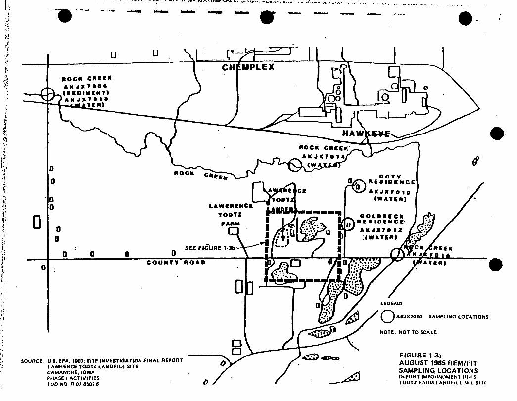
l-3a August 1985, REM/FIT Sampling Locations 1-4
l-3b August 1985, REM/FIT Sampling Locations 1-4
1-4 Autumn 1986, REM II Field Investigation Program 1-7
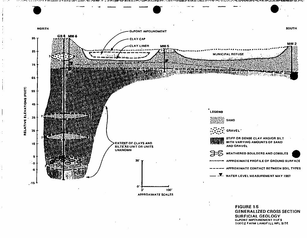
1-5•
Generalized Cross-section, Surficial Geology 1-7
1-6 Potentiometric Surface Map, October 1986 1-8
2-1 Proposed Topographic Mapping Locations 2-3
2-2 Source Area Characterization Studies 2-6
2-3 Hydrogeologic Investigation Studies 2-8
2-4 Typical Monitoring Well 2-12
2-5 Typical Staff Gage 2-13
to l o\ Surface Water Investigation Studies 2-13
3-la Master Project Schedule 3-1
3-lb Possible Default Schedule 3-1

*■TABLES • •
# FollowsPage
1-1 Site Chronology 1-3
1-2 Results of Analysis: InitialSite Inspection August 1980 1-3
1 1-3 Results of Analysis: Surface WaterSamples, August 1985 1-4
11
1-4 Results of Analysis: pH and Conductivity:Groundwater and Surface Water Samples— August 1985
♦i-4
1 1-5 Results of Analysis: Private Well SamplesAugust 1985 /
1-4
1 1-6 Results of Analysis: Sediment Samples—August 1985 1-4
1 1-7 Water Levels in Monitoring Wells 1-8
•11
1-8 Summary of REM II Organic Analytical Results for Water Samples CollectedFrom the Six Monitoring Wells 1-10
1-9 Average Values for Selected REM II Inorganic Compounds and Parameters for Water Samples Collected from theSix Monitoring Wells 1-12
1 2-1 Analytical Parameters * 2-6
1 2-2 Rationale for Soil Boring Locations 2-8
1
2-3 Rationale for Monitoring Well and Piezometer Locations 2-10
l1 3-1 Project Milestones 3-1
GLT678/64
i
■ iv
I
EXECUTIVE SUMMARY
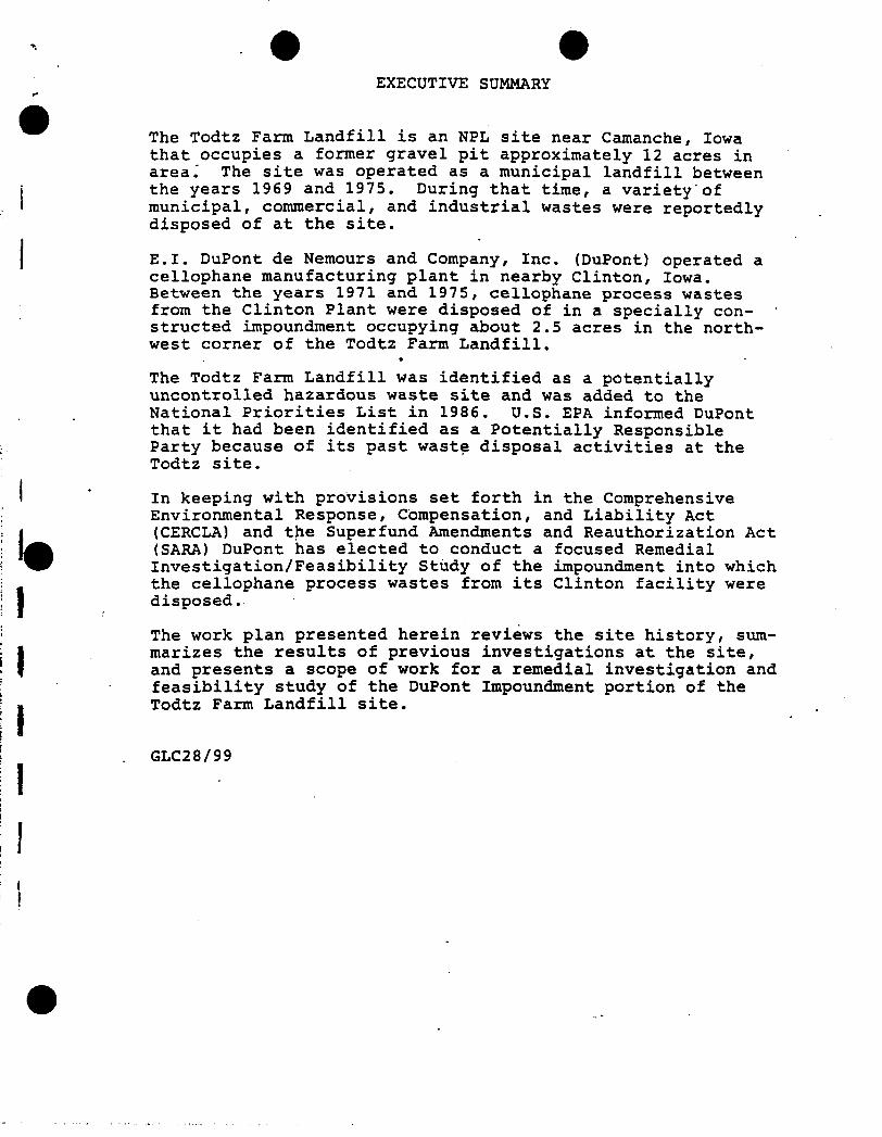
The Todtz Farm Landfill is an NPL site near Camanche, Iowa that occupies a former gravel pit approximately 12 acres in area.' The site was operated as a municipal landfill between the years 1969 and 1975. During that time, a variety'of municipal, commercial, and industrial wastes were reportedly disposed of at the site.
E.I. DuPont de Nemours and Company, Inc. (DuPont) operated a cellophane manufacturing plant in nearby Clinton, Iowa. Between the years 1971 and 1975, cellophane process wastes from the Clinton Plant were disposed of in a specially constructed impoundment occupying about 2.5 acres in the northwest corner of the Todtz Farm Landfill.
»
The Todtz Farm Landfill was identified as a potentially uncontrolled hazardous waste site and was added to the National Priorities List in 1986. U.S. EPA informed DuPont that it had been identified as a Potentially Responsible Party because of its past waste disposal activities at the Todtz site.
In keeping with provisions set forth in the Comprehensive Environmental Response, Compensation, and Liability Act (CERCLA) and the Superfund Amendments and Reauthorization Act (SARA) DuPont has elected to conduct a focused Remedial Investigation/Feasibility Study of the impoundment into which the cellophane process wastes from its Clinton facility were disposed.
The work plan presented herein reviews the site history, summarizes the results of previous investigations at the site, and presents a scope of work for a remedial investigation and feasibility study of the DuPont Impoundment portion of the Todtz Farm Landfill site.
GLC28/99

Section 1 INTRODUCTION
This work plan describes the focused Remedial Investigation/ Feasibility Study (RI/FS) of the DuPont Impoundment portion of the Todtz Farm Landfill NPL Site in Camanche, Iowa.DuPont has retained CH2M HILL, Inc. as its technical consultant to provide work assignment planning and engineering assessment services during the course of the RI/FS.
GOALS OF THE RI/FS
The goals of the DuPont Impoundment RI/FS are to:
o Determine whether substances in or migrating from the DuPont Impoundment pose a threat to human
• health or the environment.
o Collect a sufficient quantity of legally and scientifically defensible data to support a feasibility study of the DuPont Impoundment.
o Develop and propose a cost-effective remedialaction program for the DuPont Impoundment which meets the goals set forth in CERCLA and SARA.
BACKGROUND
TODTZ FARM LANDFILL NPL SITE HISTORY
The Todtz Farm Landfill NPL Site consists of a 12-acre parcel of land located on the 120-acre Todtz family farm, 1-1/4 miles west of Camanche, Iowa (Figure 1-1). The site can be more precisely described as being located ii} the S.E. 1/4 of the S.W. 1/4 of the S.W. 1/4 of Section 29, Township 81 North, Range 6 East of the 5th Principal Meridian, Clinton County, Iowa (1).
A 39-acre tract containing the future NPL site was purchased by Mr. Lawrence Todtz in 1958 for agricultural purposes (3). Between 1959 and 1969, a 12-acre parcel (the future NPL site) was leased to Andrew Determan for the purposes of mining sand and gravel. Determan operated a blacktop paving business in nearby Camanche.
Review of available records shows that the 12-acre parcel containing the gravel pit was operated as a landfill by Donald Null from 1969 to late 1970. After this time, the pit area was leased by Lawrence and Fern Todtz to McManus Brothers Excavating and Crane Service for the purposes of operating a municipal landfill. The lease was signed on December 23,1970 and was renewed annually up to 1975. A permit to
1-1

1000 MOO
SCALE IN f CET
SOURCE: USOS CLINTON AND CAMANCHC 7 i MINUTE QUADRANGLE MAPS
FIGURE MSITE LOCATION MAP
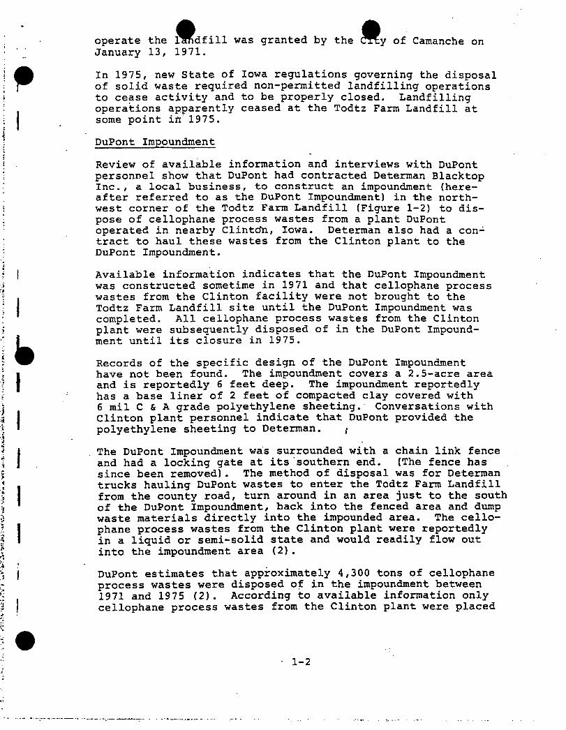
operate the landfill was granted by the CTty of Camanche on January 13, 1971.
In 1975, new State of Iowa regulations governing the disposal of solid waste required non-permitted landfilling operations to cease activity and to be properly closed. Landfilling operations apparently ceased at the Todtz Farm Landfill at some point in 1975.
DuPont Impoundment
Review of available information and interviews with DuPont personnel show that DuPont had contracted Determan Blacktop Inc., a local business, to construct an impoundment (hereafter referred to as the DuPont Impoundment) in the northwest corner of the Todtz Farm Landfill (Figure 1-2) to dispose of cellophane process wastes from a plant DuPont operated in nearby Clintcfn, Iowa. Determan also had a contract to haul these wastes from the Clinton plant to the DuPont Impoundment.
Available information indicates that the DuPont Impoundment was constructed sometime in 1971 and that cellophane process wastes from the Clinton facility were not brought to the Todtz Farm Landfill site until the DuPont Impoundment was completed. All cellophane process wastes from the Clinton plant were subsequently disposed of in the DuPont Impoundment until its closure in 1975.
Records of the specific design of the DuPont Impoundment have not been found. The impoundment covers a 2.5-acre area and is reportedly 6 feet deep. The impoundment reportedly has a base liner of 2 feet of compacted clay covered with 6 mil C & A grade polyethylene sheeting. Conversations with Clinton plant personnel indicate that DuPont provided the polyethylene sheeting to Determan. *
The DuPont Impoundment was surrounded with a chain link fence and had a locking gate at its southern end. (The fence has since been removed). The method of disposal was for Determan trucks hauling DuPont wastes to enter the Todtz Farm Landfill from the county road, turn around in an area just to the south of the DuPont Impoundment, back into the fenced area and dump waste materials directly into the impounded area. The cellophane process wastes from the Clinton plant were reportedly in a liquid or semi-solid state and would readily flow out into the impoundment area (2).
DuPont estimates that approximately 4,300 tons of cellophane process wastes were disposed of in the impoundment between 1971 and 1975 (2). According to available information only cellophane process wastes from the Clinton plant were placed
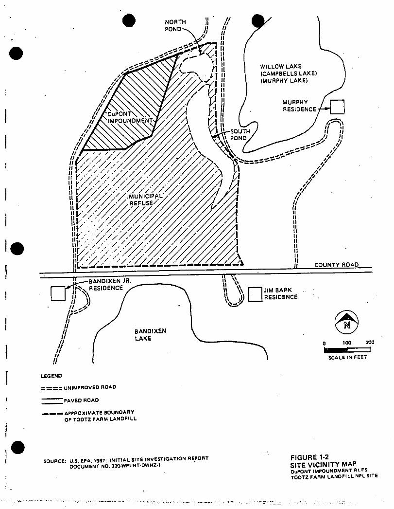
LEGEND
- Z UNIMPROVED ROAD
'PAVED ROAD
APPROXIMATE BOUNDARY
OF TOOTZ FARM LANDFILL
FIGURE 1-2 SITE VICINITY MAPDuPONT IMPOUNDMENT RI.FS TOOTZ FARM LANDFILL NPL SITE
SOURCE: U.S. EPA. 1987: INITIAL SITE INVESTIGATION REPORT
DOCUMENT NO. 320-WPI-RT-DWHZ-1

in the DuPont Impoundment. A description of the cellophane manufacturing process is provided in Attachment 1.
DuPont records indicate that cellophane process wastes from the Clinton plant could have been generated from four possible areas; the Chemical Area, the Casting Area, the Coating Area and, to a lesser degree, the Laboratory. The feed stocks and potential wastes from these processes are also provided in Attachment 1.
At the time of closure, the waste'mass within the DuPont Impoundment was approximately 2 feet thick having an estimated volume of 8,000 cubic yards. According to DuPont records, waste disposal .operations at the DuPont Impoundment were terminated in March 1975. The waste mass was then capped with up to 2 feet of "red sugar clay." DuPont stopped producing cellophane at the Clinton facility in January 1985 because of a reduction in demand for this product.
NPL Listing
The Todtz Farm Landfill was originally identified as a potential uncontrolled hazardous waste site in 1979. A preliminary site inspection was conducted by U.S. EPA's Field Investigation Team in 1980. The site was given a Hazard Ranking System (HRS) score of 52.11 in March 1985 and was subsequently proposed to the National Priorities List (NPL) in September 1985 and was eventually added to the NPL in June 1986. A site chronology is presented in Table 1-1.
PREVIOUS INVESTIGATIONS
An initial investigation of the Todtz Farm Landfill site was conducted in August 1980 for U.S. EPA by the Ecology and Environment Field Investigation Team (iS&E/FIT) under the REM/FIT contract. The investigation consisted of a site walkthrough, interviewing several nearby residents (including Mrs. Todtz and Robert McManus, owner and operator, respectively, of the Todtz Farm Landfill) and collecting samples from an onsite surface water body (North Pond) and a sample from the Bandixen well, located to the South of the site. The results of these analyses are presented in Table 1-2. The analytical results show evidence of plasticizers (phthalates) in both onsite surface water and nearby residential well water (the Bandixen well) in very low concentrations. Apparently, it was the results of this sampling event that led to the Todtz Farm Landfill site being nominated to the NPL in June 1985.
In 1983, the University of Iowa Hygienic Laboratory conducted a study of impacts from industrial and waste disposal activity on the Rock Creek watershed. Because this information was
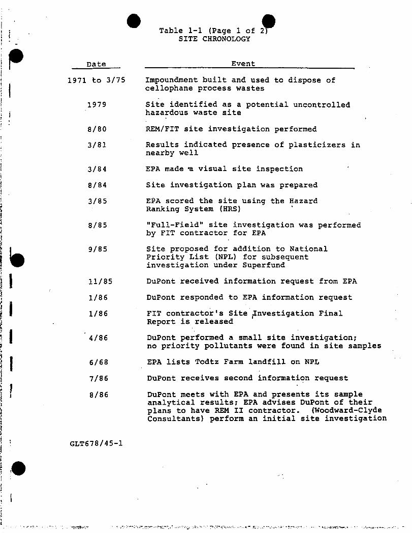
Table 1-1 (Page 1 of 2 SITE CHRONOLOGY
Date___ ___________________ Event
1971 to 3/75 Impoundment built and used to dispose of cellophane process wastes
1979 Site identified as a potential uncontrolled hazardous waste site
8/80 REM/FIT site investigation performed
3/81 Results indicated presence of plasticizers in nearby well
3/84 EPA made *a visual site inspection
8/84 Site investigation plan was prepared
3/85 EPA scored the site using the HazardRanking System (HRS)
8/85 "Full-Field" site investigation was performed by FIT contractor for EPA
9/85 Site proposed for addition to NationalPriority List (NPL) for subsequent investigation under Superfund
11/85 DuPont received information request from EPA
1/86 DuPont responded to EPA information request
1/86 FIT contractor's Site jlnvestigation FinalReport is released
’ 4/86 DuPont performed a small site investigation; no priority pollutants were found in site samples
6/68 EPA lists Todtz Farm landfill on NPL
7/86 DuPont receives second information request
8/86 DuPont meets with EPA and presents its sample analytical results; EPA advises DuPont of their plans to have REM II contractor. (Woodward-Clyde Consultants) perform an initial site investigation
GLT678/45-1
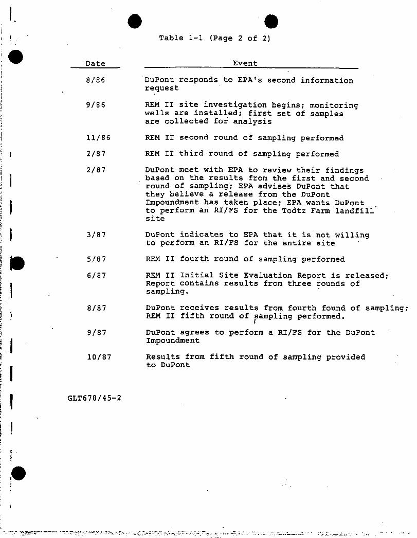
Table 1-1 (Page 2 of 2)
Date __________________ Event
8/86 DuPont responds to EPA's second information request
9/86 REM II site investigation begins; monitoring wells are installed; first set of samples are collected for analysis
11/86 REM II second round of sampling performed
2/87 REM II third round of sampling performed
2/87 DuPont meet with EPA to review their findings based on the results from the first and second round of sampling; EPA advises DuPont that they believe a release from the DuPontImpoundment has taken place; EPA wants DuPont to perform an RI/FS for the Todtz Farm landfill site
3/87 DuPont indicates to EPA that it is not willing to perform an RI/FS for the entire site
5/87 REM II fourth round of sampling performed
6/87 REM II Initial Site Evaluation Report is released; Report contains results from three rounds of sampling.
8/87 DuPont receives results from fourth found of sampling; REM II fifth round of sampling performed.
9/87 DuPont agrees to perform a RI/FS for the DuPont Impoundment
10/87 Results from fifth round of sampling provided to DuPont
GLT678/45-2

I
II
IIIII
Table 1-2RESULTS OF ANALYSIS ESE/FIT INITIAL
SITE INSPECTION—AUGUST 1980 TODTZ FARM LANDFILL SITE
Element/CompoundLagoon
Sample (ug/1)
Bandixen Well Sample
(ug/1)
Aluminum 367 34
Barium 37 26
Copper 28 20
Iron 486 226
Manganese 45 <2
Nickel 32 <10
Sodium 226 7
Di-n-Butyl-pthalate 30 7
Bis(2pethylhexyl)-pthalate 25 12
6-methylhept1ester-2- propenoic acid* 10 —
Acetic acid; 2-ethylhexylester* — 60
2-methoxy-2-methyl propone* — 2
f
Source: U.S. EPA 1984. Proposed activities for the siteinvestigation of the Lawrence Todtz Farm site Camanche, Iowa TDD No. R-07-8402-17A
♦Tentatively identified compounds.—Not identified or quantified.
GLT678/46
il
■w

not directly related to the Todtz Farm Landfill site, the results of this study will not be discussed further.
In 1984, U.S. EPA Region VII REM/FIT prepared a scoping document for additional studies to be conducted at the Todtz Farm Landfill Site (TDD No. R-07-8402-17A). This document was the basis for a subsequent "full-field” site investigation conducted by E&E/FIT personnel between August 6 and August 8, 1985.
The investigation involved the collection of surface water, sediment, and groundwater from surface water bodies and residential water supply wells in the vicinity of the Todtz Farm Landfill site. Sampling locations are shown in Figures l-3a and l-3b. Samples collected from these locations were analyzed for pesticides, total metals, and volatile and semivolatile organic compounds. The analytical results of the August 1985 sampling event are presented in Tables 1-3 through 1-6.
The organic compounds identified in surface water samples included 2-butanone and bis(2-ethylhexyl)phthalate (semivolatile organics). Metals identified in surface water samples were, for the most part, below detection limits. The sample from the South Pond has 17 of the 19 tested metals above detection limits but below U.S. EPA action levels. Pesticides were not detected in any samples.
The compounds identified in groundwater samples included 17 metals and 2 organic compounds. The metal concentrations were all below established U.S. EPA action levels. The organic compounds were 2-butanone and bis(2-ethylhexyl)phthalate. Pesticides were not detected in any of the samples.Bis(2-ethyl hexyl)phthalate was not used in the cellophane manufacturing process at the Clinton plant.
iThe compounds identified in the sediment samples included metals and organics. The volatile organic compound that was detected was 2-butanone (all samples). Other identified volatile compounds included methyl chloride, acetone, and toluene. The only pesticide detected was 4,4'-DDT, which was detected in the sample from Bandixen Lake. No pesticides were ever used at the Clinton plant.
Although acetone, phthalates, and 2-butanone were detected in a number of samples, they were also found in field blanks. This suggests that these compounds may have resulted from field or laboratory contamination (3).
The report summarizing the findings of the August 1985 field investigation (U.S. EPA 1986) presents the following conclusions :
1-4
-} '. i|■rt.fc
$:*r
-I*.Si.*K\l*i
y' VJ
SOURCE. U S EPA. 1987; SITE INVESTIGATION FINAL REPORT
LAWRENCE TOOTZ LANDFILL SITE CAMANCHE. IOWA PHASE I ACTIVITIES
IUO NO n 01 850? 6
LEGEND
AKJX7010 SAMPLING LOCATIONS
NOTE: NOT TO SCALE
FIGURE 1-3a AUGUST 1985 REM/FIT SAMPLING LOCATIONSDuPONT IMPOUNDMENT 1(1/1 S T0DT2FAIIM LANDFILL Nl‘l Sill

LEGEND
Q AKJX7009 SAMSUNG LOCATIONS
NOTE: NOT TO SCALE
SOURCE: U.S. EPA. 1987. SITE INVESTIGATION FINAL-REPORT LAWRENCE TOOTZ LANOFILL SITE CAMANCHE. IOWA PHASE I ACTIVITIES
• TOO NO. R-07-8S07-6
FIGURE 1*3b AUGUST 1985 REM/FIT SAMPLING LOCATIONSOuPONT IMPOUNDMENT RI.-PS TOOTZ FARM LANDFILL NPl SITE

'".‘•‘•'V7. .■ ■ l) 'TUhattlrv ‘ * *** 1* llXf I? JlMt'-H' _v
TABLE 1-3 SURFACE kMER SAHPIES
TOOTZ LANDFILL CAMANCHE, IOHA
AUGUST, 1985
AKJX7013 Ruck Creek Background
AKJX7004North
Lagoon
AKJX7007South
Laqoon
AKJX7014 Rock Creek
Upstream
AKJX7015 Rock Creek Downstream
AKJX7014Willow
Lake
AKJX7017Bandixen
Lake
AKJX70ier Tleld Blank
TOTAL HETALS —rng7T]------
A1 uni nil* 540 250. • 750 • 1200. • 310 210 120 M 84.0 NAntimony 54.0 H U 270 • 54.0 H 54.0 H 54.0 H 54.0 H 84.0 HOarlun 09.014 84.0 H 420 • 84.0 M 84.0 M 84.0 H B4.0 H 84.0 HBerylllue U U 25.0 • U U U U UCadmiin U U 25.0 • U U U U UCalclu* 70000. 14000. 11000. 45000. 59000. 15000. 13000. 1000 HChromlun U U 45.0 • U U U 9.50 M • UColbalt U U 100 • U U U U UCopper 22.0 H U 110 • U U U U U1 ron 510 220 1500. • 1100. • 350. 24(1. 240 84.0 HLead 4.50 5.00 7.50 • 4.40 • 7.40 • 8.50 • 5.00 UHagnealun 51000. 1B000. 8500. 51000. 30000. 22000. 33000. 230 NManganese 91.0 55.0 250 • 75.0 110. • 57.0 32.0 UNickel U 52.0 H 110 • U U 21.0 M * U UPotaaalin 950 H 2500. H « 4700 M • 940 H ■ 950 H 1100. H 2300. H ■ 950.Sodl in 11000. 240000. • 510000. 8700. 9200. 31000. • 11000. 1500.Tin U U 240 • U U U U • UVanadlua U U 120 • U U U U UZinc
VOLATILE ORGANICS
11.0 H 27.0 • 55.0 • 40.0 • U U 12.0 M • 15.0
2 - But an on a 17.0 U U 19.0 21.0 20.0 15.0Acetone U U U U U U U 23.0
22.0SCHI-VOLATILCS
Bia(2-Ethylhexyl). U U U 140.0 38.0 U U Uphthalate
* - Above background conconcentratIonH - Value is above detection limit, but below qualification limit.U - Undetected.
Source: U.S.EPA, 1986; Site Investigation Pinal ReportLawrence Todtz Landfill Site Camanche, Iowa Phase I Activities TDD | R-07-8507-6
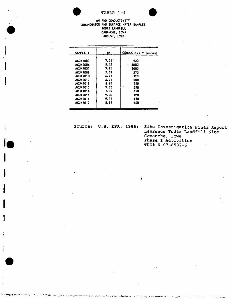
TABLE 1-4
pH AND CONDUCTIVITYgroundwater and surface water samples
TOOTZ LANDTILL CAMANCHE, IOWA
AUGUST, 1905
SAMPLE 1 pH CONDUCTIVITY (unhos)
AKJX7004 7.31 .900AKJX7006 9.13 - 1000AKJX7007 9.25 2000AKJX7008 7.19 570AKJX7010 6.75 720AKJX7011 6.71 800AKJX7012 6.63 750AKJX7013 7.75 550AKJX7014 7.89 650AKJX7015 7.00 720AKJX7U16 9.14 430AKJX7017 8.87 460
Source: U.S. EPA, 1986; Site Investigation Final ReoortLawrence Todtz Landfill Site Camanche, Iowa Phase I Activities TDD# R-07-8507-6
i
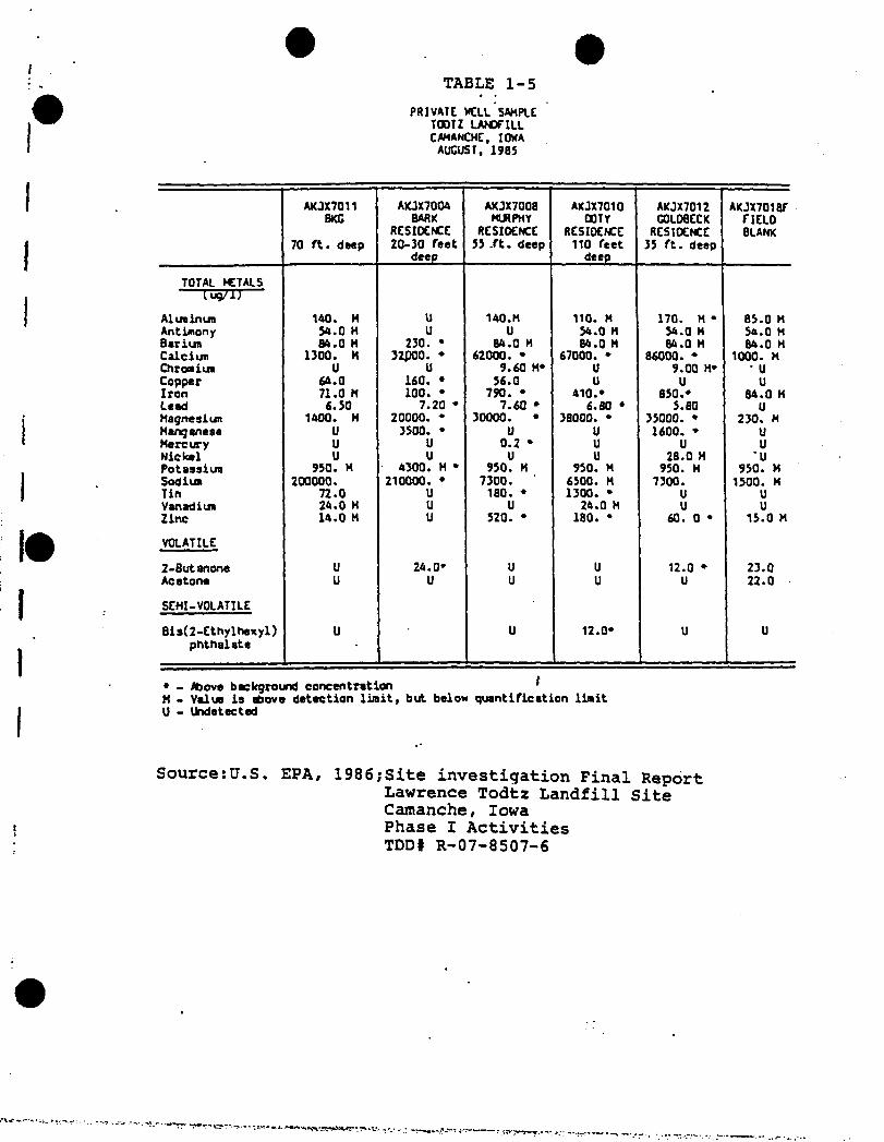
TABLE 1-5
PRIVATE WELL SAMPLE TOOTZ LAHjriLL CAHANCHE, IOWA
AUGUST, 196S
II
I#
II
AKJX7011BKG
70 ft. deep
AKJX7004BARK
RESIDENCE 20-30 feet
deep
AKJX7008 Ml* PHY
RESI0ENCE55 .ft. deep
AKJX7010DOTY
RESIOENCE 110 feet
deep
AKJX7012G0L08ECK
RESIOENCE35 ft. deep
AKJX7Q18PriELOBLANK
TOTAL «TALS—n^7TJ—
Alua in un 140. M U 140. M 110. H 170. M • 85.0 HAntimony 54.0 M U U 54.0 M 54.0 H 54.0 MBariun 84.0 M 230. * 84.0 M 84.0 H 84.0 H 84.0 MCalciun 1300. M 32P00. * 62000. • 67000. • 86000. • 1000. MChromium U U 9.60 M* U 9.00 H* ■ UCopper 64.0 160. « 56.0 U U UIron 71.0 M 100. • 790. * 410.* 850.* 84.0 MLead 6.50 7.20 * 7.60 * 6.80 » 5.80 UHagnesiun 1400. M 20000. • 30000. • 38000. ♦ 35000. * 230. MManganese U 3500. * U U 1600. * UMercury U U 0.2 * U U UNickel U U U U 28.0 M UPotassiun 950. M 4300. M * 950. M 950. M 950. H 950. MSodiua 200000. 210000. • 7300. 6500. M 7300. 1500. MTin 72.0 U 180. « 1300. * U UVanadiui 24.0 M U U 24.0 M U UZinc 14.0 M U 520. * 180. • 60. 0 • 15.0 M
VOLATILE
2-Butanone U 24.0* U U 12.0 * 23.0Acetone
SEMI-VOLATILE
U U U U U 22.0
8is(2-Ethylhexyl)phthalate
U U 12.0* U U
* - Above background concentration 'M - Value ia above detection limit, but below quantification limit U - Undetected
i
Source:U.S, EPA, 1986;Site investigation Final ReportLawrence Todtz Landfill Site Camanche, Iowa Phase I Activities TDD# R-07-8507-6

TABLE 1-6
sediment samples TOOTZ LAfOflLL. CAHANCHE, IOWA
AUGUST, 1985
AKJX7005 Rock Creek
BKG
AKJX7001North
LagoonArea
AKJX7002SouthLagoon
Area
AKJX7003Willow
Lake
AKJX7009Bandixen
Lake
TOTAL HETALS(mg/kg)
Aluninun 4900. 2500. 2800. 2600. 2400.Antimony U 36.0 * 48.0 * U 39.0 •Arsenic U U 7.20 * U UBariun ISO. 57.0 M 75.0 M 70.0 M 60.0 MCalcium 9300. 4400. 6300. 1300. M 1300.MCnromiun U U 8.6 ♦ U UCapper 22.0 U U U UIron 15000. 6000. 9400. 4800. 6300.Lead 17.0 7.80 19.0 • 8.60 UMagnesium 4000. 2100. 3000. 1500. M 1900. MManganese 520. 240. 290. 95.0 130.Nickel U U 26.0 • 17.0 M * 19.0 M *Potassium 990.M 640. H 850. M 790.H 680.MSilver 9.40 U 8.10 U USodium 1000.M 850.M 920. M 800.M 690. HZinc U 21.0 * 54.0 * U 12.0 *
VOLATILE ORGANICS
Methylene Chloride U U U 29.0 * 6.00 *Acetone 22.0 U U U 18.02-Butanone 27.0 24.0 43.0 , 30.0 * 21.0Toluene U U 8.00 * U
SEHIVOLATILES
Di-n-8utylphthalata U 510. • U UPyrene 410. U U U4-Methylphenol U U U 340.
PESTICIDES
4,4*. DDT U U U 4.60 •
* - Above background concentrationM - Value is above detection limit, but below quantification
U - Undetected.
Source: U.S. EPA, 1986; Site Investigation Final ReportLawrence Todzt Landfill Site Camanche, Iowa Phase I Activities TDD# R-07-8507-6

"Field observation made during the site investigation found the DuPont Impoundment with an adequate soil cap and good vegetation cover on the cap. No leachate seeps or major erosion problems exist on or below the DuPont Impoundment.All surface water runoff from the DuPont Impoundment is confined within the depressional area. The possibility of a surface water contaminant release from 'the DuPont Impoundment appears remote.
The combined chemical data from the preliminary assessment, site investigation, and Rock Creek study do not indicate a groundwater release. Private well samples were relatively free of contamination. The compound bis (e-ethylhexyl)phtha- late was found in low concentration in two private wells.This compound is used as a plasticizer and is widely distributed in the environment. A surface water release from the site is unlikely and Would be confined to the depressional area in which the industrial waste cell is located. Although questions exist as to the exact content of the DuPont Impoundment and the effectiveness of its liner, presently available information does not indicate any environmental contaminant release from the DuPont Impoundment."
Remedial planning activities apparently continued under the REM II contract following termination of the REM/FIT contract in September 1986. The basis for these continued studies is unclear given the conclusions of the site characterization activities conducted under REM/FIT.
In September 1986, U.S. EPA Region VII REM II Contractor, Woodward-Clyde Consultants (WCC), submitted a Scope of Work and Quality Assurance Project Plan for an expanded investigation at the Todtz Farm Landfill Site "to obtain information pertinent to a decision to implement 3 Remedial Investigation/ Feasibility Study (RI/FS) ■" (3).
The-investigation was carried out in the Autumn of 1986 and included the installation of six monitoring wells, a deep geotechnical boring, and collecting samples from:
o Residential and monitoring wells o Surface water bodieso Sedimentso Offsite soilso DuPont Impoundment cap and waste samples
The location of monitoring wells, geotechnical boring and other environmental sampling points is shown in Figure 1-4.
A complete discussion of the findings of this investigation are presented in the "Initial Site Evaluation Report,"June 19, 1987, Document No. 320-WPI-RT-DWHZ-l. This document also presents the results of two additional rounds of
1-5

groundwater sampling collected after the Autumn 1986 site investigation activities were completed.
Subsequent to the publication of the report, two additional groundwater sampling rounds were conducted in May and August 1987.- The results of the five sampling analyses are presented in Attachment 2 of this work plan.
A summary of the findings of the investigation is presented in the following sections.
The DuPont Impoundment represents a small portion of the overall Todtz Farm Landfill site. The majority of the waste disposed of at the Todtz Farm Landfill site was placed in the municipal landfill located to the south and southeast of the DuPont Impoundment (Figure 1-2).
»Because no detailed record of landfilling operations exists for the municipal portion of the Todtz Farm Landfill site, the physical relationship between the municipal wastes and the DuPont Impoundment is not known (i.e., is not known whether the DuPont Impoundment rests on top of other land- filled wastes).
NPL SITE CHARACTERIZATION
GEOLOGY
The physiography in the vicinity of the Todtz Farm Landfill NPL Site is typified by three local provinces? the Kansan- Nebraskan Glacial Till Plain, the Iowa Erosion Surface, and the alluvial flood plain of the Mississippi River (1). The NPL site itself is situated on an outwash terrace remnant that stands about 15 to 20 feet above the present alluvial flood plain of the Mississippi River. This remnant was probably part of a more extensive outwash fterrace deposited in the late Wisconsin Age then subsequently eroded by the Mississippi River (4).
Topographically, the area is relatively flat with a few localized depressions. Somewhat marshy conditions occur in the area and become more evident as one approaches the Mississippi River (1).
In general, the subsurface of the Todtz Farm Landfill NPL Site probably consists of both alluvial and glacial deposits which overlie Silurian Age dolomites. The thickness of the unconsolidated deposits in the vicinity of the NPL site is unknown, but may range from less than 100 to as much as 200 feet. The elevation of the bedrock surface may be somewhat erratic due to karst conditions (4).
‘ 1-6

The most reliable information on geologic conditions in the immediate vicinity of the Todtz Farm Landfill Site is provided from drilling logs of the six shallow monitoring wells (depths ranging from 19 to 26.5 feet) and a deep geotechnical boring (depth 108 feet) drilled by WCC during the REM II site investigation conducted in the Autumn of 1986. The location of these wells and boring are shown in Figure 1-4.
Examination of these logs shows that the two background monitoring wells drilled in undisturbed materials (MW-1 and MW-6) encounter a minimum 22.5-foot thick layer of poorly graded fine to coarse sands interbedded with gravel which is indicative of an outwash terrace deposit. Layers of a high plasticity clay were observed in the boring log for MW-1 from 15.5 feet (relative elevation 79.5 feet) to the end of the boring at a depth of 24 feet (relative elevation 71 feet).
»Examination of the drilling log from geotechnical boring GB-6 (adjacent to monitoring well MW-6) shows a 15.5-foot thick layer of high plasticity clays interbedded with silt laminae extending from the bottom of the surficial sand and gravel unit (depth 22.5 feet, relative elevation 72.5) to a depth of 38 feet (relative elevation 57 feet). From 38 feet to the end of the boring (depth 108 feet, relative elevation -13 feet) the soils consist primarily of high to low plasticity clays interbedded with silts and occasional stringers of poorly graded clayey sand. The soils from a depth of 85 feet (relative elevation 10 feet) to the bottom of the boring contain a higher percentage of gravel and cobbles within a high plasticity clay matrix which is characteristic of glacial till. Bedrock was not encountered in this boring.
The lithologic sequence of deposits in monitoring well MW-2, located at the southern boundary of the Todtz Farm Landfill consists of 20 feet of poorly graded medium to coarse sands interbedded with gravel (bottom elevation 69 feet) underlain by at least 6.5 feet of interbedded silts and clays. MW-2 was drilled to a depth of 26.5 feet (relative elevation 62.5).
Borings for monitoring wells MW-3, MW-4 and MW-5 were drilled through the berm surrounding the DuPont Impoundment, and therefore encounter disturbed materials to varying depths. Natural deposits consisting primarily of high and low plasticity clays with silts were encountered at depths of 11.5, 15 and 15.1 feet (relative elevations 72.5, 71, and 70.9 feet) in borings MW-3, MW-4, and MW-5, respectively. These deposits may be fluvial in origin. A generalized cross section of the surficial geology in the vicinity of the site is shown in Figure 1-5.
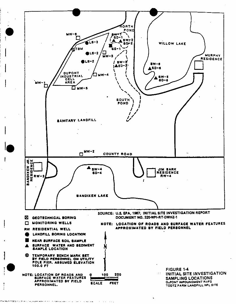
B GEOTECHNICAL BORINGSOURCE: U.S. EPA, 1987; INITIAL SITE INVESTIGATION REPORT
DOCUMENT NO. 320-WPI-RT-0WHZ-1
□ MONITORING WELLS
RW RESIDENTIAL WELL % LANDFILL BORING LOCATION
■ NEAR SURFACE 80IL SAMPLE
A SURFACE WATER AND SEDIMENT SAMPLE LOCATION
NOTE: LOCATION OF ROADS AND SURFACE WATER FEATURES APPROXIMATED SY FIELD PERSONNEL
IN
® TEMPORARY BENCH MARK SET BY FIELD PERSONNEL ON UTILITY POLE PIER. A88UME0 ELEVATION 100.0 FT
NOTE: LOCATION OF ROADS AND SURFACE WATER FEATURES APPROXIMATED BY FIELD PERSONNEL.
0 100 200
SCALE FEET
FIGURE 1-4INITIAL SITE INVESTIGATION SAMPLING LOCATIONSOuPONT IMPOUNDMENT RI/FS TODTZ FARM LANDFILL NPL SITE
RE
LAT
IVE
ELE
VA
TIO
NS
(FE
ET
)
-DuPONT IMPOUNDMENT
■CLAY CAP
SOUTH
MW 2
STIFF OR DENSE CLAY AND/OR SILT
WITH VARYING AMOUNTS OF SAND
AND GRAVEL
WEATHERED BOULDERS AND COBBLES
•.............— APPROXIMATE PROFILE OF GROUND SURFACE
-----------------APPROXIMATE CONTACT BETWEEN SOIL TYPES
-----------WATER LEVEL MEASUREMENT MAY 1987
O’ 100‘APPROXIMATE SCALES
FIGURE 15GENERALIZED CROSS SECTION SURFICIAL GEOLOGYDuPONT IMPOUNDMENT lll/TS TODTZ FARM LANDFILL NPl. SITE

HYDROLOGY/HYDROGEOLOGY
Surface Water
Surface water bodies in the vicinity of the Todtz Farm Landfill Site consist of the Mississippi River, Rock Creek, and numerous small lakes and ponds. The main channel of the Mississippi is located about 1.5 miles southeast of the Todtz site. Rock Creek is located about 2,000 feet north of the site and flows in an easterly direction to a point about 3/4 of a mile northeast of the site where it turns south- southwest and enters the Mississippi River via the Schricher Slough (1).
Small lakes and ponds are found to the north, south, and southeast of the site and are a result of either topographical depressions or past sand and gravel mining operations (.4) .
Groundwater
Review of available data indicate that the surficial sand and gravel units of the outwash terrace deposit form a shallow unconfined aquifer in the vicinity of the site. This aquifer is used as a source of drinking water by several of the private residences in the area. The shallow surface water bodies in the vicinity of the site are probably hydraulically connected to this upper aquifer.
Previously installed monitoring wells MW-1, MW-2, and MW-6 are screened in this surficial sand and gravel unit. Review of the boring logs and water level data indicate that the saturated thickness of this unit ranges from about 11 feet in the vicinity of MW-1 and MW-6 to 4 feet in the vicinity of MW-2. The characteristics of the surficial aquifer beyond the immediate vicinity of the site are unknown.
fMonitoring wells MW-3, MW-4 and MW-5 are screened in fill materials in the previously excavated areas of the site and extend into the lower silt and clay units.
Five sets of water level measurements collected from monitoring wells MW-1 through MW-6 are presented in Table 1-7.A potentiometric surface map for the upper aquifer in the vicinity of the site is presented in Figure 1-6. Water level and stratigraphic information generated during the REM II site investigations indicate that the surficial aquifer is unconfined and that the general direction of groundwater flow is to the east-southeast. No information is available or the hydraulic characteristics (i.e., hydraulic conductivity) of this sand and gravel aquifer.
Information obtained from GB-06, the only deep boring, indicate that below the surficial sand and gravel aquifer is a
1-8

TABLE 1-7
WATER LEVEE MEASUREMENTS REM II MONITORING WELLS TODTZ FARM LANDFILL SITE
Well No. Date
Well Depth to Relative Elevations (ft)Depth Water (ft) Casing Top Water Table
MW-1
MW-2
MW-3
MW-4
10- 09-86*
11- 11-86 02-16-87 05-11-87 08-10-87
23.2(72.06)
10- 09-86
11- 11-86 02-16-87 05-11-87 08-11-87
10- 09-8611- 12-86 02-17-87 05-12-87 08-12-87
10- 09-86
11- 12-86 02-17-87 05-11-87 08-11-87
25.0(63.52)
18.0(69.12)
19.0(67.17)
MW-5 10- 09-86
11- 12-86 02-17-87 05-12-87 08-10-87
17.9(68.64)
15.817.4017.6917.1218.87
17.620.3221.8321.4521.79
10.38.609.159.512.34
13.813.3913.7013.6514.75
9.49.419.42
10.12 10.81
97.06
90.52
86.19
89.17
88.64
81.3 79.66 79.37 79.9478.19
72.970.2068.69 69.07 68.73
75.9 77.5977.0476.69 73.85
75.4 75.77 75.4775.52 74.42
79.179.2479.4078.52 77.83
MW-6 10-09-86
11-11-8602-16-87 05-11-87 08-10-87
24.4 17.3(70.74) 19.83
20.19 20.03 20.77
97.84 80.578.04 77.64 77.81 77.07
* Measurements taken when well tops were surveyed.
Source: Woodward-Clyde ConsultantsCorrespondence, October 1987

t
LEGEND
•78 WATER TABLE ELEVATION
MW-2 MONITORING WELL AND *72.9 WATER LEVEL ELEVATION
SCALE IN FEET
SOURCE: U.S. EPA. 1987: INITIAL SITE INVESTIGATION REPORT
DOCUMENT NO. 320-WPI-RT-DWHZ-1
FIGURE 1-6 WATER TABLE MAP OCTOBER 9. 1986DuPONT IMPOUNDMENT RI/FS TOOTZ FARM LANDFILL NPL SITE

thick sequence of high and low plasticity clays interbedded with silts and occasional clayey sand stringers with some clayey gravel zones at depth. This sequence probably behaves as an aquitard. However, because the lateral extent, continuity or hydraulic characteristics of the more granular units observed within this sequence have not been investigated. Their importance as aquifers or migration pathways is unknown.
The dolomite and sandstone bedrock units underlying the overburden serve as sources of drinking water for several communities in the area (4). The thick sequence of cohesive soils underlying the sand and gravel outwash tend to separate the upper, unconfined groundwater system from groundwater in the lower rock formations. Because of the improbability of their hydraulic connection to the surficial sand and gravel aquifer in the vicinity of the Todtz Farm Landfill site, these units will not be discussed further.
GROUNDWATER USE
Seven residential wells have been identified in the immediate vicinity of the site. The approximate locations of the wells are shown in Figure l-3a. Detailed construction data, including well depth for the residential wells, has not been collected. Some of the wells are completed in the shallow water table aquifer, while others may be over 100 feet deep (3) .
SITE ENVIRONMENTAL QUALITY
A review of the REM II analytical data and the conclusions of the Initial Site Evaluation has been performed by CH2M HILL. The following general findings have be made.
Surface Water Quality--------------------- j"No confirmed volatile, semi-volatile, or pesticide compounds were identified in any of the surface water samples” (EPA, 1987, p. 4-5). The South Pond and, to a lesser extent, the North Pond, show some evidence of environmental degradation. Methylene chloride, a common laboratory contaminant, was identified in the South Pond sample at concentrations greater than those typically attributed to laboratory contamination. The salinity of the two onsite pond samples is 5 to 10 times greater than the salinity of the Willow and Bandixen Lake samples. The conductivity of the pond samples is 2 to 2.5 times that of the Willow and Bandixen Lake samples.
Sediment Quality
"No confirmed organic compounds were found above the quantification limit in any of the six sediment samples" (EPA,1987, p. 4-6). Dieldrin was identified in concentration
1-9

above the detection limit and below the quantification limits in the North Pond sediment sample. Toluene and tetra- hydrofuran were identified in the South Pond sediment sample. The metal concentrations in the pond and lake samples "[do] not appear to be elevated" (EPA, 1987, p. 4-6)-.
Landfill Soil Quality
"[No] volatile or semi-volatile constituents [were positively identified] in any of the landfill and/or near surface borings" sampled and analyzed by the EPA. "Numerous tentatively identified and unknown compounds from the semi-volatile fraction were detected" (3).
Residential Well Water Quality
"No volatile, semi-volatiJ.e, pesticide, or toxic metal constituents were found in any residential wells" (3). Elevated salinity and conductivity values were reported for the Bark residential well sample collected during the first sampling round. (This well is located downgradient of the DuPont Impoundment and the municipal landfill.) The salinity and conductivity of Bark well water have decreased between October 1986, when the well was first sampled by the REM II contractor and August 1987, when the last REM II sampling round was performed (see Attachment 2 for a listing of these results).
Monitoring Well Water Quality
The monitoring well organic analytical results for sampling rounds 1 through 5 are summarized in Table 1-8. Only those compounds whose presence has been confirmed by at least two sampling events are presented and discussed herein. Because the groundwater samples collected for inorganic analysis were highly turbid and were not filtered prior to analysis, the REM II inorganic analytical results (with the exception of sodium) are not presented in this discussion. The organic and inorganic analytical results are presented in full in Attachment 2.
Of the six monitoring wells installed, MW-1 and MW-6 appear to be located upgradient of the DuPont Impoundment and the municipal landfilled area. MW-3 through MW-5 are immediately adjacent to and downgradient of the DuPont Impoundment, and MW-2 is downgradient of both the DuPont Impoundment and the municipal landfilled area.
No volatile organics and only one semi-volatile organic were detected in the upgradient wells (MW-1 and MW-6). Two volatile organic compounds (benzene and chlorobenzene) were detected in the downgradient well MW-2 on at least two of the five sampling rounds. These compounds were only detected
1-10

' ... ‘ »■ MlUf Wdtfr'oVf£lA‘Aurt Lw1; *».Vti *.*41 <>»'{* ?»••. : '■ Wd"£\,:■.V*,-..t> •
" “ • ~ “Iible l-B
Suanry of REN II Oraioic Aailytidl Result* for Niter Staples Canceled Froi Iht Sii Naaitoriaf Neill
IMI-I HU-2 RN-1 MM IUI-5 hn-r
• NIN NAI FIE# NIN NRI FREB NIN NRI FREB NIN NRI FREB NIN NRI FREB NIN NR! FREB
VOlRIItC OREMICSi1R«» 15/3)CirbM Dlltlllde ID l/N 17/3) 184 4444) 15/5) •
Rcetaae - 4)4) - 2444 11/31 -
Retreat 4.BN 12/3) 4.1 11/5) 72N 11/5) - 120N ll/S) -
lolutae I.BH 11/31 I44H 12/51 35N 11/5) 144) 8844 13/5) . •
Rethyleae Chloride 244 (1/51 RIB) 11/5) - 7344 17/5) -
IttrtbydrolwriaCM dt oleum
I244J 13/5) B74 15444) 15/5) 7444) 17444 13/5) -
II 12/31 * * " “ - “
BRSE/NEU1RM./RCIIEIIRACIRUC ORERNICSi
134) 11/5)fbtool - • - • 144 14/5)2-Netbylphraol - - - 4. IN 11/5) 2.4N 11/5) 724 .11/3)4-NtlhrlphnolPeatuhloropkeael
- - - I24J 14/5) - 1444 14/31
- - • * * 18 12/5)2,3,1,11,14-Peatiaii*
(tender ia-14-el 2IR1 12/31 • - 234 11/5) 1244 lt/5) 14) 11/5)2,2-12-Hetbtiyetkoiyl
144 11/31 484) ,17/5)CtkoirEtkiiol 212) 11/31 - - ' • 14) 11/5)1,1,4-lrilbiolue - * - • I43RJ 12/31 - 14444) 11/5)1,2,1,4-lttrithirpine • - - 4441) 11/3) 1744) II/3)
' 1,1,5,I'letritbitciat - - - 2432) 11/3) - 1784) 17/5)1,1,3-lritbnat • - - 444) 12/3) - 445 12/31Itaioic Acid • - - 344) 17/51 - 1444) 17/5)Fntnoic Acid « • - - - - 414 11/5)fictiaoic Reid 24 11/31 - - 174) 12/3) 854 11/51 144) 11/5)Demote Acid 1 11/31 - - 144 12/3) 714 11/3) - ,
Bmntpronaitc ReidRnintirtUc Acid
“ • 114)1112)
11/3)12/51
11/31
1174)344)
11/5)11/5)
2-Ntlkfl-fnttiaic Reid2,5-tioetkrl-Realtor*
lutuoic Reid
* ” * * 8.5) 144)
174)
17/3)
• • — • “ - 12/5)Holtrtlir Suitor - - - 1444) 12/3) - - 714) 12/3)lu-12-Etblrlknyll
Phtbilile tl 11/31 • - . - - 4N 12/5) - 4.7N11/51
- -
I. fetrihydrofuria bn biro ideatified 11 t (Militant. Houtvtr, lucnlrttiMi irt tale reliable It mi liRailictat lifurt beciiie m refer erne sltadird mi tied ler yiuliUtiu.
N • Coaceatratioa it belw faulilidlioi litii (USEPR) or leu Ibn caatract retired detectioa lieili IO.fl.
J • Caaoouad an lailililietlr idcatifiedi b never, caaoouad lulid to ocot ill H criterii lit it therefore nly u eitiaited elite.
- Not detected.
during the first two sampling rounds, with benzene concentrations at levels higher than the detection limit but lower than the quantification limit. Chlorobenzene was detected in concentrations ranging from 10 to 11 ug/1.
Carbon, disulfide, acetone, benzene, toluene, methlvene chloride, and tetrahydrofuran are the volatile organic compounds detected in either" MW-3, MW-4, or MW-5 during at least three sampling rounds. Only three of these six compounds (carbon disulfide, toluene, and tetrahydrofuran) were detected 100 percent of the time at at least one of these three monitoring wells.
Carbon disulfide has been detected in all three of these wells at (confirmed or estimated-J) concentrations ranging from 2 to 4,000J ug/1. Carbon disulfide was observed in both MW-3 and MW-5 during.all five sampling rounds. The carbon disulfide concentrations decreased from 2,100 to 31J ug/1 in MW-3 and increased from 1,000J to approximately 4,000J ug/1 in MW-5 during the study period. Carbon disulfide was found in MW-4 on two occasions at concentrations greater than the detection limit but less than the quantification limit.
Toluene was detected twice in MW-3 (in concentrations less than the quantification limit) and five times in MW-5 in increasing concentrations over time. Toluene concentrations increased from 700J ug/1 (round 1) to a maximum of 8,800 ug/1 (round 5) during the study period.
Tetrahydrofuran was detected in three of the five rounds in MW-3 and all five rounds in MW-4 and MW-5. The tetrahydrofuran concentrations decreased from 1,200J to 110 ug/1 in MW-3 and from 85,000J to 870 ug/1 in MW-4 and increased from 2,600J to 97,000J in MW-5 during the study period.
JPhenol, 2-methylphenol, 4-methylphenol (cresols), and four tentatively identified semi-volatile organic compounds, were detected in either MW-3, MW-4," or MW-5 during at least three sampling rounds. None of these compounds have been detected 100 percent of the time during the sampling period. Only one of these compounds was confirmed as being present in MW-4 while four were repeatedly found in MW-3 and eight were repeatedly present in MW-5. Phenol concentrations decreased from 74J to 37 ug/1 in MW-3 and have increased from 91 to 190 ug/1 in MW-5 over the study period. Reported 4-methylphenol concentrations have ranged from 40 to 120J ug/1 in MW-3 and from 150J to 1,000 ug/1 in MW-5. The concentrations of this compound in MW-5 appears to be increasing over time.
The reported values for sodium, chloride, alkalinity, and conductivity in water from MW-3 through MW-5 were higher than
1-11

the corresponding values for the upgradient wells (MW-1 and MW-6) and the downgradient well (MW-2). In general, sodium and conductivity values were the highest in MW-3, followed by those in MW-4 and MW-5, followed by those in MW-2 and finally MW-1 and MW-6. The alkalinity and pH of water from MW-3 was unusually high compared to values for the other monitoring wells (see Table 1-9).
POSSIBLE RELATIONSHIP BETWEEN IMPOUNDMENT AND ENVIRONMENTAL QUALITY
Several of the constituents identified in monitoring wells at MW-3 through MW-5 and in the onsite ponds have been reported as being used at the DuPont Clinton Plant and may have been disposed of in the DuPont Impoundment. Specifically, these are carbon disulfide, toluene, tetrahydrofuran, and cresols. The exact relationship between the DuPont Impoundment and environmental quality is not known at this point in time and is the subject of the proposed work program contained within this work plan.
POTENTIAL RECEPTORS
EPA concluded that the primary concern from a risk assessment perspective is groundwater constituent migration. Potential receptors are the nearby residents that rely on groundwater as a source of drinking water and nearby surface water bodies (3).
At this point in time, results indicate that residential well water quality has not been dramatically affected by past NPL site waste disposal practices and .that an immediate risk to public health and the environment does not exist. Currently, insufficient information exists to assess the future risk posed by the DuPont Impoundment.
fEPA concluded that further investigation needed to be performed to characterize the site, the impacts resulting from that contamination, and to develop the data required to evaluate remedial alternatives. The scope of work proposed to meet these needs is presented in Section 2.
GLT 678/24

Wbl l 1-?Avenqe Viluts For Stleded RED II Inorqinic Coipoundi And Pirneteri
For liter Sieple* Collided Froi The Su Aonitorinq lelli
AOHTORIH6 KELL AUASER »
AETAIS:Sodiun (»q/l)
HOH-AETALS:AlWlinity-tDtil
Chloride teq/1)
FIELD PARAAETERS: reepirtture (Celsius)
Sill nitT 10/00)ppn Condudmty (uihos)
pH (ltd uni til
HI-1 A1-2 Al-J
14 38 3840
420 414 7846
5.2 17.7 1087
13.2 14.4 12.9
0.2 0.5 7.4
485 908 9520
6.8 6.3 10.3
AI-4 AI-3 AI-6
240 1685 74
1326 3649 302
241 270 23.4
12.9 14.0 12.3
1.2 3,4 0.2
1772 4815 616
7.0 7.1 6.9
f
Section 2 RI/FS WORK PLAN
This section presents the proposed tasks to achieve the objectives set forth in Section 1.
The following RI/FS work program has been developed assuming that:
o The RI/FS work program described herein has been developed on the current assumption that the risk associated with the impoundment can be remedied by low level source control (such as encapsulation and/or capping) and some type of groundwater monitoring and that further remedial work (such as excavation and treatment of cell wastes) will not be needed.
o The current plan is that the remedial investigation and feasibility study will address both the source area and groundwater and that such RI/FS will be completed by August 8, 1988, unless the aforesaid risk assessment indicates that the current assumptions are wrong.
o If the risk assessment indicates that groundwater monitoring will not be an adequate response and remedial groundwater work may be needed, the remedial investigation/feasibility study will be split to address the source area and the groundwater as separate operable units.
o In the event that the groundwater is handled as asubsequent operable unit, such groundwater operable unit remedial investigation/feasibility study will be completed by April 17, 1989.
o In the event that the source area is handled as anoperable unit, such source area operable unit remedial investigation/feasibility study will be completed by August 8, 1988. If the risk assessment indicates that more then low-level source control may be required as part of the remedial action, the source area operable unit remedial investigation/ feasibility study will be completed by April 17, 1989.
REMEDIAL INVESTIGATION
The remedial investigation portion of the study comprises the following tasks.
2-1

o TaW 1—:o Task 2—]
o Task 3—]
o Task 4—:
o Task 5—:
9 Task 6—]o Task 7—:
o Task 8—1o Task 9—1
o Task 10-o Task 11-o Task 12-
The objectives and
Investigation Support Preliminary Endangerment Assessment Prepare Site Base MapsPotential Receptor Survey and EvaluationSource Area CharacterizationHydrologic/Hydrogeologic InvestigationEnvironmental SamplingData Validation and ManagementData Evaluation-Endangerment Assessment-Prepare Remedial Investigation Report-Project QC
sented below.
Many of the proposed tasks will require access to property . owned by others. The program described below assumes that access to neighboring properties will not be a problem.
TASK 1—INVESTIGATION SUPPORT
Investigation support involves those activities which are necessary before the remedial investigation can be implemented. This task is subdivided as follows.
Subcontractor Procurement
Several of the investigative activities that will be conducted during the course of the RI will require the services that can only be provided by outside contractors. Services expected to be subcontracted are:
o Aerial Photography and Topographic Mapping
o Drilling, Soil Sampling, and. Monitoring Well Installation
o Test Pit Excavation
o Analytical Testing
Time expended by the CH2M HILL Project Team in preparing and evaluating subcontractor bid documents will be covered under this task. Subcontract administration is also included in this task.
Equipment Procurement and Site Setup
This subtask involves gathering together the equipment which will be used during the field investigation activities and setting up onsite facilities. It has been assumed that an office trailer will be brought to the site which will serve
■ft •••V
. 2-2
as both an onsite command post and temporary storage facility for field equipment. It will also be necessary to establish decontamination facilities for the heavy equipment that will be used onsite as well as a secure storage area for containing any potentially contaminated materials generated during the course of the remedial investigation. Such wastes include disposable protective clothing, drill cuttings, and purge water from contaminated wells.
TASK 2—PRELIMINARY ENDANGERMENT ASSESSMENT
Data generated under the REM II site investigations will be reviewed by a CH2M HILL analytical data QC expert to determine its usability for performing a preliminary endangerment assessment.
Data passing the QC screening will be used to perform a preliminary endangerment assessment to evaluate risk to potential human receptors. The results of this preliminary endangerment assessment will be used to help develop a preliminary list of FS source control alternatives.
TASK 3—PREPARE SITE BASE MAPS * 2
The objective of this task is to develop site base maps of sufficient detail and quality to:
o Present the results of the remedial investigation and feasibility study
o Serve as remedial design base maps
Because of the focused nature of this investigation, it will be necessary to prepare two sets of maps. The areas to be mapped are shown in Figure 2-1.
fThe first map will show the Todtz Farm Landfill and surrounding properties. This map will be a topographic map having a scale of 1 inch equal to 200 feet with a contour interval of2 feet. The area delineated in Figure 2-1 is approximately 4,800 feet by 7,200 feet and will fit on a 24-inch by 36-inch plan sheet. The second map will focus on the DuPont Impoundment portion of the Todtz Farm Landfill. This map will be prepared at a scale of 1 inch equal to 25 feet with a contour interval of 1 foot and will cover an area approximately 600 feet by 900 feet.
Topographic mapping services will be subcontracted to a quali fied firm specializing in photogrammetry. If possible, exist ing aerial photographs will be utilized when developing these topographic maps. However, it may be necessary to conduct an aerial survey of the area if the recent aerial photographs are not at a useable scale.
2-3

TOPOGRAPHIC SUnVC V ARCA
SOURCE: U S CPA. HS7. INITIAL SITE INVESTIGATION REPORT OOCUMCN1 N0.3M WTI RT OWM2 I
FIGURE 2-1TOPOGRAPHIC SURVEY AREASIbtltlNI IMI‘Ol*NhSi| N1 MINS

A local surveyor will be retained to provide ground truthing of selected points on the base map. The surveyor will be requested to establish a benchmark in the vicinity of the DuPont Impoundment so that the elevations of the measuring points on the proposed monitoring wells can be referenced to a common datum. The proposed benchmark will be referenced to the nearest USGS benchmark.
TASK 4—POTENTIAL RECEPTOR SURVEY AND EVALUATION
To help focus the efforts of the"remedial investigation, potential receptor’s (residential water supply wells) of constituents that may have been released from the DuPont Impoundment will be surveyed and evaluated. The list of potential receptors will be limited to those residents within the envelope indicated in Figure 2-1 that use the uppermost unconfined sand and gravel aquifer as a source of drinking water.
The survey of these residences will consist of a search of Iowa State Geological Survey records to obtain information on well construction details and will also include interviewing the selected residents to obtain demographic information and additional information about their well construction.
If physically accessible, the potential receptor wells will be sounded to determine the depth to static water and the total depth. In addition, consideration may be given to geophysically logging these wells using a natural gamma probe.The hydrogeologic data will be used to determine strati- • graphic conditions and possible migration pathways.
These activities will only be performed if. permission is granted by the residential well owner. Each resident will be contacted and informed of the activities to be performed and the reasons why they are being conducted prior to inception. If the owner of a. particular wdll expresses concerns, raises objections, or refuses access to DuPont representatives, no further attempts will be made to evaluate that well.
The information obtained from the receptor survey will be important to the endangerment assessment and will be useful when evaluating the fate and transport of DuPont Impoundment related constituents which may have been released to the environment.
TASK 5—SOURCE AREA CHARACTERIZATION
The objectives of this task are to:
o Evaluate the thickness and volume of the waste mass within the DuPont Impoundment
2-4
o Determine the physical state and chemical characteristics of the waste mass
o Evaluate the integrity of the polyethylene and clay liners
o Evaluate the materials beneath the impoundment
The proposed method of achieving these objectives is presented below.
Test Pit Excavation
Given the relatively thin layer of waste contained within the impoundment (reported to be approximately 2 feet thick), three test pits will be excavated within the Impoundment at the locations shown in_Figure 2-2. Excavating test pits is preferable to drilling because it allows field team members to proceed slowly and observe the impoundment's profile as the test pit is being excavated. This method also provides a greater degree of confidence that the polyethylene liner, if present will not be torn. An additional advantage of test pit excavation is that, by being able to observe the waste profile, the field team will be able to collect more representative waste samples.
Test pit excavation services will be subcontracted to a qualified firm experienced with work on hazardous waste sites.Test pits will be excavated using either a small excavating machine such as a "Bobcat" to minimize chances of the excavating machine damaging the impoundment cap or a track mounted vehicle. A small machine is preferable to a larger, rubber tired backhoe, because the competency of the cover materials, and stability of the underlying waste mass is unknown. As an alternative, a track-mounted backhoe could be utilized; however, it may not be cdst-effective to mobilize a machine of this size for the limited amount of work to be performed.
The pit will be excavated in 6-inch passes to allow the project team to make observations on the thickness and integrity of the cover materials, and the character and distribution of the waste mass. Each test pit will be logged and photographed by CH2M HILL geologist or geotechnical engineer experienced in test pit excavation at hazardous waste sites. It is expected that Level B personal health and safety protection will be required of all personnel participating in test pit excavation.
To minimize contamination of the ground surface, excavated cover soils and waste materials will be placed on plastic sheeting. Cover soils and waste materials will be segregated as much as possible. Some of the excavated waste materials
2-5
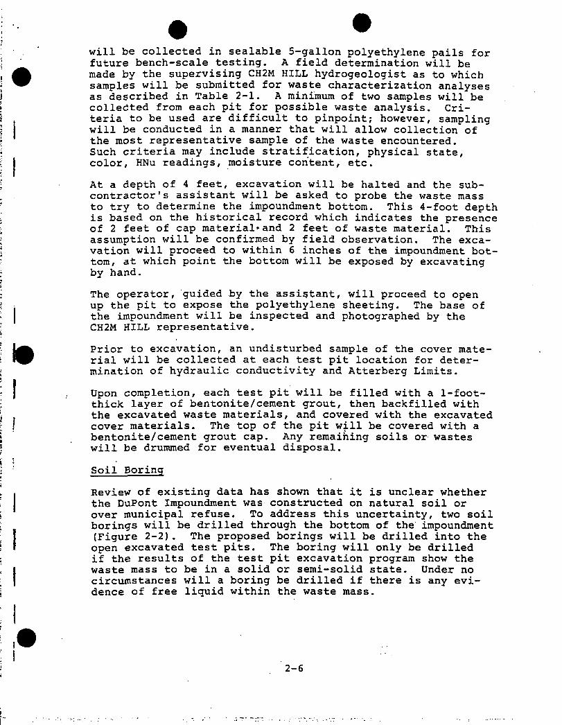
will be collected in sealable 5-gallon polyethylene pails for future bench-scale testing. A field determination will be made by the supervising CH2M HILL hydrogeologist as to which samples will be submitted for waste characterization analyses as described in Table 2-1. A minimum of two samples will be collected from each pit for possible waste analysis. Criteria to be used are difficult to pinpoint; however, sampling will be conducted in a manner that will allow collection of the most representative sample of the waste encountered.Such criteria may include stratification, physical state, color, HNu readings, moisture content, etc.
At a depth of 4 feet, excavation will be halted and the subcontractor's assistant will be asked to probe the waste mass to try to determine the impoundment bottom. This 4-foot depth is based on the historical record which indicates the presence of 2 feet of cap material*and 2 feet of waste material. This assumption will be confirmed by field observation. The excavation will proceed to within 6 inches of the impoundment bottom, at which point the bottom will be exposed by excavating by hand.
The operator, guided by the assistant, will proceed to open up the pit to expose the polyethylene sheeting. The base of the impoundment will be inspected and photographed by the CH2M HILL representative.
Prior to excavation, an undisturbed sample of the cover material will be collected at each test pit location for determination of hydraulic conductivity and Atterberg Limits.
Upon completion, each test pit will be filled with a 1-foot- thick layer of bentonite/cement grout, then backfilled with the excavated waste materials, and covered with the excavated cover materials. The top of the pit will be covered with a bentonite/cement grout cap. Any remaining soils or wastes will be drummed for eventual disposal.
Soil Boring
Review of existing data has shown that it is unclear whether the DuPont Impoundment was constructed on natural soil or over municipal refuse. To address this uncertainty, two soil borings will be drilled through the bottom of the impoundment (Figure 2-2). The proposed borings will be drilled into the open excavated test pits. The boring will only be drilled if the results of the test pit excavation program show the waste mass to be in a solid or semi-solid state. Under no circumstances will a boring be drilled if there is any evidence of free liquid within the waste mass.
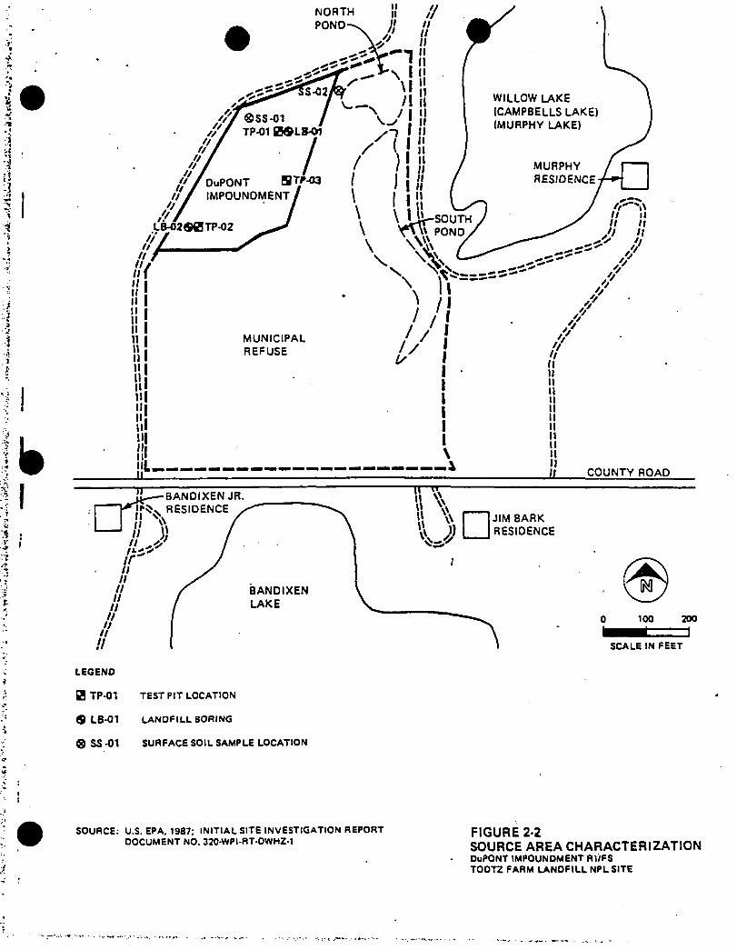
LEGEND
(B TP-01 TEST PIT LOCATION
9 LB-01 LANDFILL BORING
® SS -01 SURFACE SOIL SAMPLE LOCATION
SOURCE: U.S. EPA. 1987: INITIAL SITE INVESTIGATION REPORT DOCUMENT NO. 320-WPI-RT-OWHZ-1
FIGURE 2-2SOURCE AREA CHARACTERIZATIONDuPONT IMPOUNDMENT fll/FS TOOTZ FARM LANDFILL NPL SITE

Table 2-1 (Page 1 of 2) ANALYTICAL TEST PARAMETERS
A■ ENVIRONMENTAL SAMPLES
Volatile Compounds5
BenzeneCarbon tetrachlorideChlorobenzene1,2-dichloroethane1.1.1- trichloroethane1.1- DICHL0R0ETHANE1.1.2- trichloroethane1.1.2.2- tetrachloroethane Chloroethane2-chloroethylvinyl ether Chloroform1.1- dichloroethene Trans-1,2-dichloroethene1.2- dichloropropane Trans-1,3-dichloropropene Cis-1,3-dichloropropene Ethylbenzene Methylene chloride Bromomethane BromoformBromodichloromethane Dibromochloromethane Tetrachloroethene TOLUENETrichloroetheneVinyl chlorideAcetone2-butanoneCARBONDISULFIDE2-hexanone4-methyl-2-pentanone Styrene Vinyl acetate Total xylenes BUTYL ACETATE*ETHYL ACETATE* TETRAHYDROFURAN*
Acid Extractable Compounds3,
2.4.6- trichlorophenol p-chloro-m-cresol2-chlorophenol2.4- dichlorphenol 2-4,dimethylphenol 2-nitrophenol 4-nitrophenol2.4- dinitrophenol4.6- dinitro-2-methylphenol• PentachlorophenolPhenolBenzoic acid2-methylphenol4-me thylpheno12,4,5-trichlorophenolCRESOLS*
Metalsb
Aluminum SodiumArsenic ThalliumBarium VanadiumBeryllium ZincCadmiumCalciumChromiumCobalt,Copper'IronLeadMagnesiumManganeseMercuryNickelPotassiumSeleniumSilver
aEPA hazardous substance list of organic compounds.
Bold-faced compounds indicate those known to be .associated with DuPont's waste, monitoring wells and landfill boring water samples will be tested for dissolved metals only. Residential wells will be tested for both total and dissolved metals.♦-Compounds to be spiked for during analysis.
GLT678/67-1
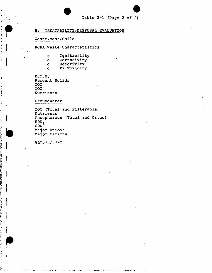
*'***
*'•.'•
»••».
-«
. I-*
4**-
/-
IbI
Table 2-1 (Page 2 of 2)
B. TREATABILITY/DISPOSAL EVALUATION
Waste -Mass/Soils
RCRA Waste Characteristics
o Ignitabilityo Corrosivityo Reactivityo EP Toxicity
B.T.U.Percent SolidsTOCTOXNutrients
Groundwater
TOC (Total and Filterable) NutrientsPhosphorous (Total and Ortho) BOD_CODMajor Anions Major Cations
GLT678/67-2
l
I
f
JI1
)

The test pits into which the landfill exploration borings will be drilled may be widened somewhat to allow the drillers room to work.
To minimize the chances for downward migration of contaminants, the polyethylene liner at the drilling location will be carefully cut away and a large diameter (24-inch) hole will be dug approximately 1/2 foot into the liner material. This hole will then be filled with a bentonite/cement grout into which will be driven a 14-inch-diameter steel casing.The casing will be driven approximately 1 foot into the liner material. At this point, a 24-inch-diameter cardboard cement form will be placed around the casing and filled with bentonite/cement grout to permanently fix the casing in place. The trench will then be backfilled to grade and the cement allowed to set for a minimum of 24 hours before drilling will continue. After the grout has set, the inside of the sealed 14-inch-diameter casing will be reamed out to the bottom of' the casing using a 14-inch-diameter roller bit and bentonite mud as the drilling fluid. The roller bit and rods will be removed, and the boring will be advanced using 4-1/4-inch- inside-diameter hollow stem augers. If possible, the first liner soil sample will be obtained using a thin-walled sampler (Shelby tube). This sample will be submitted to a geotechnical laboratory to determine vertical hydraulic conductivity and Atterberg Limits. The remainder of the boring will be sampled at 1.5-foot intervals using a 2-inch- diameter split-barrel sampler in accordance with ASTM Standard D 1586 for the Standard Penetration Resistance Test in Soils. The boring will be advanced to the top of the water table, which is estimated to be within 5 feet of the bottom of the impoundment.
The boring will be logged by an experienced CH2M HILL hydrogeologist or geotechnical engineer. Each soil sample will be physically described using the Unified Soil Classification System and will be screened with an organic vapor analyzer to determine whether volatile organic constituents are present. If native soils are encountered beneath the liner, a soil sample from the water table will be collected and submitted for analysis of the compounds listed in Table 2-1. A grab sample of the groundwater will be collected regardless of whether or not natural soils are encountered. The results of these analyses may indicate whether contaminants have migrated from the impoundment to groundwater. Landfill boring and test pit sampling procedures are described in Section 6 of the Quality Assurance Project Plan (QAPP).
Upon completion, the boring will be filled with a thick bentonite slurry which will be introduced from the bottom of the
•2-7

boring to the top via the tremie method. The slurry will be allowed to freely discharge to the surface of the bottom of the pit. The slurry will be injected simultaneously as the augers are removed. The top of the boring and the area immediately surrounding the 12-inch-diameter casing will be covered with a 1-foot thick layer of dry granular bentonite. This area will in turn be covered with a sheet of 30-mil plastic and covered with a geotextile fabric before backfilling with a 1-foot-thick layer of bentonite cement grout. The remainder of the test pit will be backfilled with excavated waste material, followed by excavated cover materials. Any remaining cuttings, excavated soils, and waste materials will be drummed and stored in a secure area onsite pending proper disposal.
TASK 6—HYDROLOGIC/HYDROGEOLOGIC INVESTIGATION
The objectives of this task are to:
o Better define the subsurface stratigraphy in the vicinity of the site
o Better define the groundwater flow system, particularly the relationship of the unconfined upper aquifer to underlying hydrostratigraphic units and adjacent surface water bodies
o Determine the hydraulic transmission characteristics of selected hydrostratigraphic units encountered
o Identify subsurface contaminant migration pathways
o Evaluate the magnitude and extent of groundwater contamination attributable to releases from the DuPont Impoundment f
The.investigation proposed in the following section is intended to achieve these objectives.
Geotechnical Borings
To better define the subsurface stratigraphic relationships in the vicinity of the Todtz Farm Landfill, five deep soil borings will be drilled and sampled at the locations shown in Figure 2-3 (designated by the prefix GT). The rationale and proposed depth of each boring is presented in Table 2-2. All borings will be advanced using mud rotary techniques.
Four of the soil borings will be advanced to bedrock which is expected to be greater than 100 feet below ground surface. The fourth (GT-04) will be advanced to a depth of approximately 60 feet below ground surface to determine the
2-8

!I
i
LEGEND
PROPOSED WELLS AND BORING
■ GT-01 GEOTECHNICAL BORING
ADP-01IS) SHALLOW MONITORING WELL
A DP-01 (D) DEEP MONITORING WELL
$ PZ-01 PIEZOMETER
EXISTING WELLS AND BORING
O GB-8 GEOTECHNICAL BORING*
• MW-5 MONITORING WELL*
‘INSTALLED BY WCC DURING INITIAL
SITE INVESTIGATION. FALL 1986
SOURCE: U.S. EPA. 1987: INITIAL SITE INVESTIGATION REPORT
OOCUMENT NO. 320-WPI-RT-OWHZ-1FIGURE 2-3HYDROGEOLOGIC INVESTIGATIONOuPONT IMPOUNDMENT RI/FS TOOTZ FARM LANDFILL NPL SITE
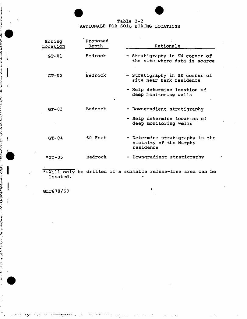
Table 2-2RATIONALE FOR SOIL BORING LOCATIONS
BoringLocation
GT-01
GT-02
GT-03
GT-04
*GT-05
*-Will only located.
ProposedDepth
Bedrock
Rationale
Stratigraphy in SW corner of the site where data is scarce
Bedrock Stratigraphy in SE corner of site near Bark residence
Help determine location of deep monitoring wells
Bedrock - Downgradient Stratigraphy
- Help determine location of deep monitoring wells
60 Feet
Bedrock
- Determine stratigraphy in the vicinity of the Murphy residence
- Downgradient stratigraphy
be drilled if a suitable refuse-free area can be
GLT678/68f

stratigraphy^^ the vicinity of the Murphy residential well which is reported to be completed at a depth of approximately 55 feet below ground surface.
Because of the possibility of encountering contaminated groundwater in the upper aquifer at GT-02, GT-03, and GT-05, the surficial aquifer will be cased off to prevent downward migration of contaminants into any lower aquifer units encountered.
The boring for GT-05 will be drilled 2 feet into the upper confining unit using a 7-7/8-inch-diameter roller, bit using mud rotary techniques. The drilling tools will be removed and the boring will be filled with a thick bentonite/cement grout via the tremie method. A 6-inch-diameter casing will be placed in the grout-filled hole and driven an additional 2 feet into the confining unit. The casing will be allowed to set 24 hours before drilling is continued.
The grout will be reamed out with a 5-7/8-inch-diameter roller bit, and the borehole will be further advanced using mud rotary drilling methods.
Each geotechnical boring will be sampled at 5-foot intervals using a standard split spoon sampler following ASTM Standard D 1586 for the Standard Penetration Resistance Test. Upon refusal, the rods and drilling tools will be removed and the bedrock will be cored 10 feet using NX-sized core to confirm the presence of bedrock. The core barrel will be removed and the boring will be geophysically logged using natural gamma resistivity and spontaneous potential to identify any breaks in stratigraphy not encountered while split spoon sampling. Following completion of geophysical logging, the borehole will be abandoned by injecting a thick bentonite slurry from the bottom of the boring to the ground surface using the tremie method. Grout injection will be simultaneous with auger removal. ‘
Each boring will be logged by an experienced CH2M HILL hydrogeologist or geotechnical engineer. Samples will be described using Unified Soil Classification System terminology. Samples will be collected for grain size analysis and/or Atterberg Limits based on changes in stratigraphy.The decision to submit a sample for geotechnical analysis (OVA deflections of 10 PPM or greater) will be made in the field by the supervising geologist or engineer but in no case will exceed five samples per boring.
Information obtained from the soil boring program will help to determine the need for, or the depth at which, deep monitoring wells will be installed, should an appropriate hydro- stratigraphic unit be encountered. The stratigraphic information is also necessary to identify potential migration
.2-9
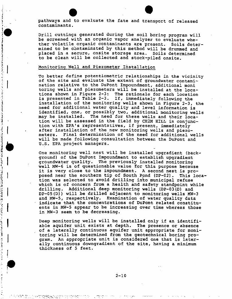
pathways and to evaluate the fate and transport of released contaminants.
Drill cuttings generated during the soil boring program will be screened with an organic vapor analyzer to evaluate whether volatile organic contaminants are present. Soils determined to be contaminated by this method will be drummed and placed in a secure, onsite storage area. Soils determined to be clean will be collected and stock-piled onsite.
Monitoring Well and Piezometer Installation
To better define potentiometric relationships in the vicinity of the site and evaluate the extent of groundwater contamination relative to the DuPont Impoundment, additional moni toring wells and piezometers will be installed at the locations shown in Figure 2-3: The rationale for each locationis presented in Table 2-3. If, immediately following the installation of the monitoring wells shown in Figure 2-3, the need for additional water quality and level information is identified, one, or possibly two, additional monitoring wells may be installed. The need for these wells and their location will be assessed in the field by CH2M HILL in conjunction with EPA's representatives, if present, immediately after installation of the new monitoring wells and piezometers. Final determination of the need for additional wells will be made following consultation between the DuPont and U.S. EPA project managers.
One monitoring well nest will be installed upgradient (background) of the DuPont Impoundment to establish upgradient groundwater quality. The previously installed monitoring well MW-6 is of questionable value for this purpose because it is very close to the impoundment. A second nest is proposed near the southern tip of South Pond (DP-02). This location was selected to avoid drilling into municipal refuse which is of concern from a health and safety standpoint while drilling. Additional deep monitoring wells (DP-03(D) and DP-05 (D)) will be drilled adjacent to monitoring wells MW-3 and MW-5, respectively. Examination of water quality data indicate that the concentrations of DuPont related constituents in MW-5 appear to be increasing over time whereas those in MW-3 seem to be decreasing.
Deep monitoring wells will be installed only if an identifiable aquifer unit exists at depth. The presence or absence of a laterally continuous aquifer unit appropriate for monitoring will be determined from the geotechnical boring program. An appropriate unit is considered one that is laterally continuous downgradient of the site, having a minimum thickness of 5 feet.
2-10
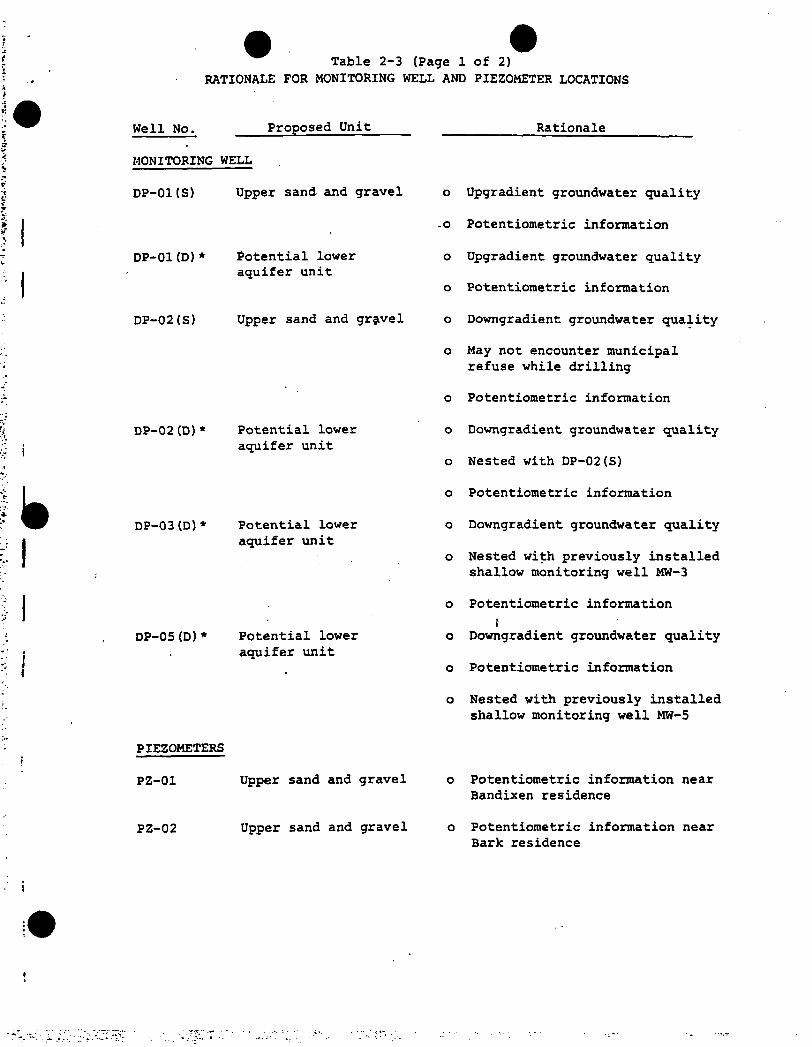
Table 2-3 (Page 1 of 2)
RATIONALE FOR MONITORING WELL AND PIEZOMETER LOCATIONS
Well No. Proposed Unit_____ ___________ Rationale
MONITORING WELL
DP-01(S) Upper sand and gravel o Upgradient groundwater quality
DP-01(D)* Potential lower aquifer unit
DP-02(S) Upper sand and gravel
DP-02 (D)* Potential lower aquifer unit
-o Potentiometric information
o Upgradient groundwater quality
o Potentiometric information
o Downgradient groundwater quality
o May not encounter municipal refuse while drilling
o Potentiometric information
o Downgradient groundwater quality
o Nested with DP-02(S)
o Potentiometric information
DP-03(D)* Potential lower aquifer unit
o Downgradient groundwater quality
o Nested with previously installed shallow monitoring well MW-3
o Potentiometric information
iDP-05(D)* Potential lower o Downgradient groundwater quality
aquifer unito Potentiometric information
o Nested with previously installed shallow monitoring well MW-5
PIEZOMETERS
PZ-01 Upper sand and gravel o Potentiometric information nearBandixen residence
PZ-02 Upper sand and gravel o Potentiometric information nearBark residence

Table 2-3 (Page 2 of 2)
Well No. Proposed Unit Rationale
PIEZOMETERS (Cont1 d)
PZ-03 Upper sand and gravel o Determine hydrologic regime of Willow Lake
PZ-04 Upper sand and gravel _o Help determine relationshipbetween South Pond, Willow Lake and shallow aquifer
‘Installation of deep wells dependent upon findings of soil boring program. If no identifiable aquifer unit is defined, no deep piezometers will be installed!
GLT678/69
I

Four piezometers (PZ-01, PZ-02, PZ-03, and PZ-04) will be installed adjacent to geotechnical borings (GT-01, GT-02,GT-03, and GT-04, respectively) at the locations shown in Figure 2-3. Piezometers will be installed immediately after completion of the geotechnical boring at each location. The relative elevations of each piezometer measuring point will be determined and water levels collected. The resulting information on flow direction will help to determine final monitoring well locations. The purpose of these piezometers to better assess the relationship between the surface water bodies and the upper aquifer groundwater flow system. As such, the piezometers will be installed in the upper aquifer unit.
This information is needed to determine whether the surface water bodies are groundwater discharge areas, or whether they are flow-through lakes. The information obtained is important to the analysis of the fate and transport of constituent released from the DuPont Impoundment and to the identification of contaminant migration pathways.
The borehole for the monitoring wells will be advanced using hollow stem augers (6.25-inch I.D.). Augers of this size allow sufficient annular space between the well and the auger wall to introduce the filter pack and seal. If alternative drilling methods need to be used, only methods using clear water, air, or cable tool will be allowed.
To be consistent with previous sampling efforts, all monitoring wells will be constructed of 2-inch-nominal-diameter threaded, flush-joint 316 stainless steel riser pipe. Shallow wells will be fitted with a 10-foot length of No. 10 slot, continuous wire wrap 316 stainless steel screen. The length of screen on the deep wells will be 5 feet. All screen bottoms will be capped prior to installation. All riser pipes and screens will be steam cleaned prior to installation. All joints will be wrapped with Teflon thread tape to promote water tight seals.
Wells will be joined section by section directly inside the auger or casing. Shallow wells will be installed such that the screened interval will be 3 feet above and 7 feet below the water table. If the formation is considered to be sufficiently coarse and graded, as determined from experienced field judgement, the formation will be allowed to collapse around the screen as the auger or casing is withdrawn, forming a natural filter pack. If the formation is not suitable, an artificial filter pack consisting of a medium to coarse flint or silica sand will be installed to a minimum of 3 feet above the top of the screened interval. The remainder of the annular space will be filled with a thick bentonite slurry to within 5 feet of the ground surface. The slurry will be introduced from the top of the filter pack to within 5 feet
2-11

*' **
*»!
of the ground surface via the tremie method. Slurry emplacement will be simultaneous with auger or casing removal.
Each well will be fitted with a threaded or slip stainless steel cap. Each well will have a minimum 2-foot stickup which will be painted a bright color to make it easily visible. The upper 5 feet of the annular space will be filled with a thick bentonite cement grout into which will be placed a 4- or 6-inch-diameter protective steel casing with locking cap. A 2-foot diameter area around each casing will be dug out to a depth of 12 inches, which will be filled with concrete to anchor the protective casing. The concrete apron will be sloped away from the casing to promote runoff. Wells located in potentially high traffic areas will be surrounded by three concrete filled, 4-inch-diameter guard posts set at 120-degree angles to each other. A typical well construction diagram is show in Figure*2-4.
Following installation, each monitoring well and piezometer will be developed until substantially free of sediment and until pH and conductivity are stable to the satisfaction of the CH2M HILL hydrogeologist. Wells will be developed using the double tube air lift or surge and bail methods.
Piezometers will be constructed of 2-inch-diameter flush joint, Schedule 40 PVC with 5-foot long factory-slotted screens and will also be installed using hollow stem auger- ing methods. Construction procedures will be similar to those used for monitoring wells.
Acruifer Testing. Following completion of the drilling program, variable head tests (slug tests) will be conducted on all of the newly installed monitoring wells and piezometers as well as the previously installed wells to determine values of hydraulic conductivity. Variable head tests will be conducted using pressure transducers ahd an electronic data logger. Tests will be performed in triplicate to lend statistical support to the values obtained.
In these tests, the water level in each well is depressed with nitrogen gas until a steady level is achieved. The pressure is then instantaneously released, and the rate of rise is recorded electronically by means of a pressure transducer coupled to an electronic data logger. At the completion of the test, the data are transferred to the hard disk of a portable personal computer and backed up to a floppy disk. The data can then be manipulated to obtain values of hydraulic conductivity using Hvorslev’s method for slug test analysis.
Water Level Monitoring. All new and existing monitoring wells and piezometers will be surveyed to establish horizontal location and elevation of the measuring points. Elevation
2-12
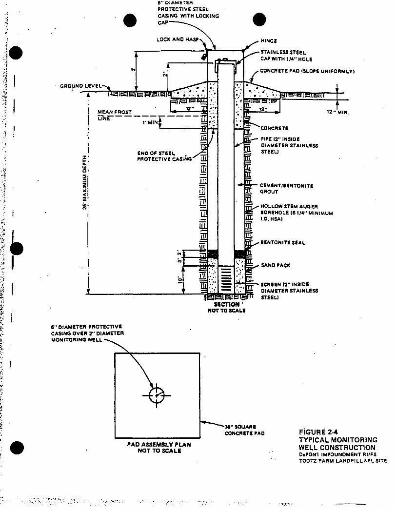
i
I
• j
t
■< ii
as
6" DIAMETER
PROTECTIVE STEEL
6" OIAMETER PROTECTIVE
CASINO OVER 2" OIAMETER
MONITORING WELL
NOT TO SCALE
FiGURE 2-4TYPICAL MONITORING WELL CONSTRUCTIONDuPONI IMPOUNDMENT RI/FS
TOOTZ FARM LANDFILL NPL SITE

measurements will be taken on the stainless steel or PVC riser pipe. The measuring point will be designated by a chisel mark. All elevations will be referenced to the benchmark established as part of the topographic mapping. All wells will be located horizontally to within plus or minus 5 feet. Vertical elevations of measuring points will be made to the nearest 0.01 foot.
Water levels will be collected on a.monthly basis from all monitoring wells and piezometers for the duration of the RI. Water levels will be collected by DuPont personnel from the nearby Clinton plant and reported to CH2M HILL for analysis and inclusion in the hydrogeologic data base. An electric water level indicator graduated in 0.01-foot increments will be used.
Hydrologic Studies
Staff Gages. To further determine the relationship of adjacent water bodies to the uppermost aquifer, it is proposed to install staff gages in the North and South Ponds, Willow and Bandixen Lakes.
Each staff gage will consist of a board or iron pipe driven into the bottom of the lake or pond with a sledge hammer. A plomb bob and level will be used to install the stake straight and plomb. A scale graduated in 0.1-foot increments with the "zero" being placed at the top of the staff gage will be bolted to each stake. The top of each staff gage will be surveyed and its vertical elevation determined to the nearest 0.01 foot and tied into the site datum. Absolute surface water level elevations can be obtained by subtracting the observed water level from the elevation of the top of the staff gage. A typical staff gage is represented schematically in Figure 2-5.
fWater level measurements will be collected monthly by DuPont personnel from the Clinton plant and reported to CH2M HILL for inclusion in the hydrologic data base. Surface water level measurements will be collected concurrently with ground- water level measurements. The information obtained will be used in evaluating the water balance for the site, which is important to fate and transport evaluation. The proposed staff gage locations are shown in Figure 2-6.
Bathymetric Sounding. The approximate depths of the North Pond, South Pond, and Willow Lake will be obtained by taking depth measurements at approximately 150-foot centers. A minimum of two readings in the North Pond, three readings in the South Pond, and roughly nine readings on Willow Lake will be taken. Measurements will be obtained from a boat using a weighted measuring tape. The approximate locations are shown in Figure 2-6.
2-13
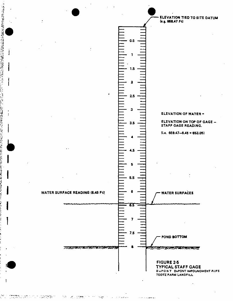
euevAiiun lieu lUSIffc DATUM(«.|. 669.47 Ft)
IIII1
— 5.5
WATER SURFACE READING (8.45 Ft); {~~~~ 8
— 8.S
0.5
1.5
2.5
3.5
4.5
7.5
fZ
ELEVATION OF WATER -
ELEVATION ON TOP OF GAGE - STAFF GAGE READING.
(i.t. 659.47—6.45 m 653.05)
WATER SURFACES
POND BOTTOM
FIGURE 2-5TYPICAL STAFF GAGEOuPONT DuPONT IMPOUNDMENT RI/FS
TOOTZ FARM LANDFILL
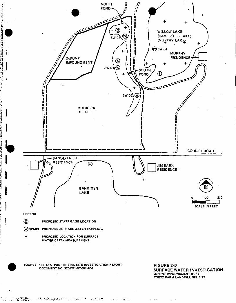
NORTHPOND
IT—<T------
|\BANDIXEN JR. RESIDENCE
BANDIXENLAKE
LEGEND
(?) PROPOSED STAFF GAGE LOCATION
@SW-03 PROPOSED SURFACE WATER SAMPLING
□ JIM BARK RESIDENCE
V 100 200a
SCALE IN FEET
PROPOSED LOCATION FOR SURFACE
WATER DEPTH MEASUREMENT
SOURCE: U.S. EPA, 1987; INITIAL SITE INVESTIGATION REPORT DOCUMENT NO. 320-WPI.RT-DWH2-1
FIGURE 2-6SURFACE WATER INVESTIGATIONDuPONT IMPOUNDMENT RI/FS TODTZ FARM LANOFILL NPL SITE
The objective of this subtask is to obtain sufficient information of the configuration of each water body to roughly calculate the volume. This is not intended to be a precise exercise but is intended to provide an order-of-magnitude estimate of the volume. These volume calculations will be based'on a plane area times an average depth.
The information will be used in the endangerment assessment to evaluate the effects of dilution on any related contaminants which may be discharging to these water bodies via groundwater transport.
TASK 7—ENVIRONMENTAL SAMPLING
The objectives of this task are to:
o Determine whether compounds directly related to the DuPont cellophane process wastes have been released from the impoundment
o Evaluate the distribution of DuPont-related compounds in groundwater and adjacent surface water bodies
o Collect sufficient data to determine whether DuPont- related compounds pose a threat to human health or the environment
SAMPLING
To achieve these objectives, samples will be collected from both newly installed and existing monitoring wells, residential wells, adjacent surface water bodies and surface soils. Monitoring well locations are shown in Figure 2-3. Surface water sampling locations are shown in.Figure 2-6. The total number of residential wells to be sampled will be determined following completion of Task 4 but at a minimum will include the Bark, Bandixen, and Murphy residences.
In addition to the water samples, surface soil samples will be collected from the locations shown in Figure 2-2. During the site visit in October, a white evaporate deposit was observed at these locations which may be indicative of a release from the impoundment. Sampling by media is discussed briefly below. Based on the overall RI/FS assumptions listed in the introductory portion of this section, only one seasonal round of environmental samples will be collected during the RI. These results will be confirmed during a confirmatory sampling round conducted 2 weeks after the initial sampling. If upon completion of the endangerment assessment, the original assumptions regarding risk and baseline level of remediation are not found to be valid, then additional
2-14
sampling may be required and the sampling program described below will be revised.
GROUNDWATER SAMPLING
Groundwater samples will be collected from newly-installed and existing monitoring wells, residential wells and grab samples from landfill borings (discussed in Task 5).
Monitoring Wells
Groundwater samples will be collected from the new shallow monitoring wells and any deep monitoring wells installed, as well as the six existing shallow wells. All wells (new and existing) will be purged prior to sampling to remove stagnant water or stratified constituents. Groundwater elevation measurements will be obtained prior to purging. Monitoring well sampling procedures are described in detail in Section 6 of the QAPP. Samples will be analyzed for the constituents listed in Tables 3-4 and 3-5 of the QAPP.
Residential Wells
A minimum of three downgradient residential wells will be sampled during this task; however, this number could change depending on the results of detailed well evaluation and survey (Task 4). Grab samples will be obtained from the cold water taps after the wells have been adequately purged to remove stagnant water. Residential well sampling procedures are discussed in Section 6 of the QAPP. Samples will be analyzed for the constituents listed in Tables 3-4 and 3-5 of the QAPP.
SURFACE WATER SAMPLING
Four surface water samples will be obtained at the locations shown on Figure 3-6 to evaluate whether groundwater contaminants associated with the impoundment are entering surface water bodies. The surface water samples will be collected near the water/sediment interface. Surface water sampling procedures are described in Section 6 of the QAPP. Samples will be analyzed for constituents listed in Tables 3-4 and3-5 of the QAPP.
SURFACE SOIL SAMPLING
Two surface soil samples will be obtained at the locations shown on Figure 2-2 to determine whether contaminants have migrated from the impoundment. A grab sample of approximately the upper 6 inches of the sediment will be collected using the method described in Section 6 of the QAPP. Samples will be analyzed for constituents listed in Tables 3-4 and 3-5 of the QAPP.
2-15
All environmental samples collected during the field program will be submitted to Environmental Testing and Certification (ETC), Inc. ETC was selected to perform the analytical testing because of their familiarity with CLP analytical protocols (having been a CLP lab in the past), past performance in working for DuPont, and prior screening by U.S. EPA Region VII, REM II contractor, Woodward-Clyde Consultants.
ETC will follow standard references for CLP protocol for the analysis of the DuPont-related compounds. To follow CLP protocols for the analysis of seledt VOCs and acid extractable compounds, analysis of the full GC/MS volatile and acid fraction scans is required. Analytical data generated as a result of this practice for non-DuPont-related compounds will be reported to EPA but will not be evaluated during subsequent project tasks.
TASK 8—DATA VALIDATION
The objective of this task is to review the data provided by ETC to evaluate whether the data are valid and to assure that required protocols were followed so that the data are legally and scientifically defensible and, therefore, usable for the endangerment assessment and the feasibility study.
The QC review of the ETC data package will be conducted by a senior CH2M HILL project team member experienced in QC review of analytical data from CLP laboratories.
TASK 9—DATA EVALUATION
RI and relevant pre-RI data will be summarized and evaluated. The data will be entered into the site data base system for efficient comparison and sorting based on factors such as type of sample, location, parameter, and concentration.Plots, contours, and maps will be revised and developed to assist in data explanations and presentations. All RI objectives will be reviewed to determine if the gathered data provides the specific information required by each task. Limitations will be identified and documented in the RI Report.
TASK 10—ENDANGERMENT ASSESSMENT
RI and relevant pre-RI data will be evaluated to estimate the hazard or potential threat to public health, welfare or the environment under the no-action alternative and future site development situations. The endangerment assessment will be consistent with U.S. EPA methods for estimating the health risks of environmental pollutants, Office of Emergency Remedial Response (OERR) guidelines for Superfund public health evaluations, and Office of Waste Programs Enforcement (OWPE) guidelines for endangerment assessments.
'2-16
The results of the assessment will be included as a chapter in the RI report. Supporting risk and transport and fate calculations will be appended and relevant references sited.
The results of the endangerment assessment will be used to determine the validity of the underlying RI/FS assumptions and the possible need for RI/FS work plan revisions.
TASK 11—REMEDIAL INVESTIGATION REPORT
A report summarizing RI activities and findings will be prepared and submitted to U.S. EPA Region VII for review and comment. The report will provide documentation of data obtained during the RI tasks.
TASK 12—PROJECT QUALITY CONTROL*
To maintain quality control throughout the course of the project, a QC review team will be assembled to provide technical guidance and review the work of the project team members.The QC review team will be comprised of three senior CH2M HILL individuals from appropriate disciplines.
i
2-17

FEASIBILITY STUDY
TASK 1—PRELIMINARY ALTERNATIVE DEVELOPMENT
During the course of the RI, the CH2M HILL project team in conjunction with DuPont personnel will develop a set of preliminary alternatives which may be appropriate to remediate threats to human health and the environment resulting from the disposal of cellophane process wastes in the DuPont Impoundment.
[This list of preliminary response actions will be continually evaluated and updated as additional data from the RI become available, and will be carried forward into the Feasibility Study.]
TASK 2—TECHNOLOGY SCREENING
A list of applicable general response actions will have been identified by the CH2M HILL project team for the DuPont Impoundment Operable Unit of the Todtz Farm Landfill and will be presented in the RI report. Based on these general response actions, specific remedial technologies enabling implementation of the actions will be identified and screened This screening will consider two criteria pertaining to appli cability:
o Physical site conditions that preclude the practical use of a technology.
o Chemical character of site contaminants that preclude the application of a technology.
Summary lists of both applicable and inapplicable remedial technologies and explanations for the.Rejection of the inapplicable technologies will be provided.
The technologies carried forward within the feasibility study will be those that are relevant given the overall RI/FS assumptions stated in the introductory portion of this section (see page 2-1).
TASK 3—ALTERNATIVES DEVELOPMENT
The purpose of this task is to identify and screen alternatives assembled from the technologies retained from Task 2.
According to available guidance on interpretation of SARA, selected remedies at Superfund sites must:
o Be protective of human health and the environment
o Be cost-effective
2-18

o Stress permanent solutions or alternatives which reduce toxicity, mobility, and volume of contaminant to the maximum extent practicable
o Attain both state and federal applicable or relevant and appropriate requirements {ARARs)
Alternatives will be developed using the concept of "permanence" as a guide. Emphasis will be placed on treatment alternatives which reduce toxicity, mobility, or volume of contaminated media. A list of alternatives will be developed ranging from permanent, low maintenance, or management solutions to less permanent solutions requiring more long-term management. Innovative technologies having the potential for better treatment performance, implementability, or lesser adverse effects than other available approaches will be carried through the screening process.
These alternatives will be developed prior to completion of the RI endangerment assessment. Some of the assumptions used to develop these alternatives may not be valid at the time of endangerment assessment completion. If any of these findings dramatically affect the determination of the appropriate level of remediation, then the FS program may need to be revised. This revision may affect the makeup of the alternatives considered during the final alternatives evaluation.
Developed alternatives will be screened using criteria of effectiveness, implementability, and cost. Cost will be used to discriminate between treatment alternatives that provide similar levels of protection but will not be used as a criterion for comparing treatment to nontreatment alternatives.To further evaluate the effectiveness of selected alternatives, bench-scale or pilot-scale tests may be conducted.These tests may also include aquifer pump testing to evaluate the effectiveness of groundwater extraction technologies.This practice is encouraged under SARA. At this time, it is assumed that alternatives can be evaluated using RI data and published technical literature.
TASK 4—ALTERNATIVES EVALUATION
The purpose of this task is to perform a detailed analysis of those alternatives that passed through the screening process. The alternatives will be analyzed in greater detail with the criteria of effectiveness, implementability, and cost, and compared to each other. Effectiveness will be evaluated in terms of whether or not an alternative 1) adequately protects human health and the environment, 2) attains state and federal ARARs, 3) significantly and permanently reduces the toxicity, mobility, or volume of hazardous constituents, and 4) is technically reliable.
2-19

Implementability factors include technical feasibility and availability of the technologies each alternative would employ, the technical and institutional ability to monitor, maintain, and replace technologies over time and the administrative feasibility of implementing the alternative.
A present-worth cost analysis will be conducted and long-term operation and maintenance costs will be evaluated. The capital and O&M cost estimates will be order-of-magnitude estimates and are expected to be accurate within a range of plus 50 and minus 30 percent.
TASK 5—PREPARE FS REPORT
An agency review draft FS report summarizing the results of the feasibility study will be prepared. The alternative remedial actions assessmeht will be documented; the draft FS report will recommend an alternative for the DuPont Impoundment.. Copies of the draft report will be submitted to the U.S. EPA for review.
A review meeting will be held between U.S. EPA and its contractors, DuPont, and CH2M HILL to discuss the draft FS report. To prepare for the meeting, EPA will provide their review comments on the Draft FS report to DuPont. The draft FS report will be modified to include U.S. EPA comments.
GLT678/62
f
2-20
'•23S5S
Section 3 SCHEDULE
The master schedule of the RI/FS tasks is presented in Figure 3-1A. Key project milestones are presented in Table'3-1. This master schedule has been prepared under the assumptions listed in the beginning of Section 2. This schedule includes provisions for one round of sampling with a confirmatory round immediately following. The sampling program will not reflect seasonal variations in groundwater quality. If, upon completion of the RI endangerment assessment, results indicate that the risk and/or the level of remediation are greater than those originally assumed, then the schedule and milestones presented in Figure 3-1A and Table 3-1 no longer apply. Instead, a new schedule will be developed after the RI/FS work program has been revised. Until a new work scope has been defined, a revised or default schedule cannot be easily prepared. However, assuming that the RI data gaps can be completed through the collection of two more rounds of sampling and analysis, an alternate schedule was prepared and is provided in Figure 3-1B.
The current schedule (Figure 3-1A) anticipates an Agency review draft FS Report will be delivered approximately 21 weeks after project inception.
Several aspects of this schedule are beyond DuPont's control. Such items include Agency turnaround time on project deliverables. For the purposes of this schedule, it has been assumed that Agency review time will be limited.
GLT678/56
f
3-1

FIGURE 3-lfl MASTER SCHEDULE—DUPONT IMPOUNDMENT fiPFfiflm iwtt fti/FS
WEEKS(1)
TASK/SUBTASK
REMEDIAL INVESTIGATION
A 6 12 16 20 24 £8 32"I-■>-- 1--►--1-- 1-- 1-K--1-- 1--1-I--j---- 1--
36—i-
TASK 1 — RI/FS SUPPORT
TASK 2 — PRE-RI ENDAN6ERMENT ASSESSMENT I ==
TASK 3 — TOPOGRAPHIC MAPPING
TASK 4 — RESIDENTIAL WELL SURVEY
TASK 5 — SOURCE AREA CHARACTERIZATION
PPPPPPPPPPPP
=WW
PPWWAAAAAAAA
TASK 6 — HYDR0LDG1C/HYDR0GEDL06IC INVESTIGATION
TASK 7 — ENVIROWENTAL SAMPLING
TASK 8 — DATA VALIDATION AND MANAGEMENT
rrwnwww» wl
UUAAAAAA
XX XX XX
TASK S — DATA EVALUATION
ILi i
TASK 10 - ENDANGERMENT ASSESSMENT
TASK 11 — PREPARE RI REPORT
TASK 12 - PROJECT QC
FEASIBILITY STUDY
R F
DD EE DD M
TASK 1 — PRELIMINARY ALTERNATIVES IDENTIFICATION
TASK 2 — TECHNOLOGY SCREENING
TASK 3 - ALTERNATIVES DEVELOPMENT
TASK 4 - ALTERNATIVES EVALUATION
TASK 5 — PREPARE FS REPORT
■I—i—I—i—|- -1—i—1
DD EEE DOM
i--1— <-----1----- 1-----1----- 1-----1-
NOTES:
(1) Schedule developed assuring zero Meek equals the first week in February.
KEY
U Field Work A Analytical Testing X Data Validation Period L Water Level Measureient = Work Period R Agency'Review Draft
* Project Deliverable D DuPont Review Period E Agency Review Period P Subcontractor Procurement M Meeting with Agency F Final Report
'TrOSs,V,\' VV:'Vr'T-. ‘ - T W'-'.' *. v ? 7

Table 3-1PROJECT MILESTONES
Project MilestoneWeeks After Project
Inception
Commence Fieldwork 1 week
Agency Review Draft RI Report 24 weeks
Meeting to Discuss RI Report 27 weeks
Final RI Report*
31 weeks
Agency Review Draft FS Report 21 weeks
Meeting to Discuss FS Report 23 weeks
Public Comment FS Report 27 weeks
GLT678/57
f

hujk. 3-ib possible dlfiui sdedule-duiki ikkunomeni okraiu urn ri/fs
KIXS(I)
TASX/SUBTASK
REKOIAL IHVESIIGAIION
TUSK I — RI/FS SUPPORI
, TASK 2 — PRE-RI ENOANGERMEMT ASSESSFEHT
TA91 3 - TOPOGRAPHIC MAPPING
TASK 4 — RESIDENTIAL ICU SURVEY
TASK 5 - SOURCE AREA CHARACTER!IATI0M
TA» ( - HYDROLOGIC/HYDROGEOLOGIC
INVESIIGAIION
TASK 7 — EWUDUENIAL SAMPLING
TASK S - DATA VAUDAIION AND MANAGEICNT
TA» S - MIA EVALUATION
TASK 10 — ENDANGERKHT ASSESS*HT
TASK II - PREPARE Rl REPOAI
TASK 12 - PROJECT OC
FEASIBILIIY SIUOY
TASK I - PRELIMINARY ALTERNATIVES
lOEHlIFICAIIW
TASK 2 -- TEOMLOGY SCREENING
TASK 3 - ALIERNAIIWS DEVELOPMENT
TA9I 4 - ALTERNATIVES EVALUATION
TA9< 3 ~ PREPARE FS REPORT
4 4 12 IE JO 24
-I—,—|—t—|—a—|—«—|—28 32 36
—I—♦—|—*—j-,40
— I-44 44 32
--I—*—l—i—I- 60•I
64— I-
64 —I-
iiinnmn
(iiiainnBipppppppppppp
•MU
mflRYYYYYYYI
PPIMUUUU 14.
IUIYYYYYI IUAAAAAA IMWIMA
I II II II II
■RminnainmsmitiinmiimnnMiissiiaauaiimu
nfinmnBun«sm>nmmiaBwaa|Mntsmannimt
DODO EEEEEE DDDD
NaaaaiaaniannaaaaaaaaaaataiaaaaaaaianaaaaaaiasiiaaaaaaaaniaiaamailBaaaaa
*--1--*--1--4--1--♦--1-
NQIESi
III Tine Iron autboriiation to proceed
121 Working document. not a
foraal deliverable
KEY
R FaaaaaaaaaRaaaaBlnaaaaaaaaaa
DDDD EEEE DO
N-I-*--1--4--1--a--1--4--1--4--1--4--1--4--1--4--1--4--1--4--1--4-1--4--1--4--1-
13) IIm6 0
41 February
fpondl
1388
II Field Work
A Analytical Testing
I Data Validation Period
L Water Level Neasureuent
••«• Work Period
R Agency Revieu Draft
• Project Deliverable
D DuPont Revieu Period
E Agency Rrvieu Period
P Subcontractor Procureuent
H Meeting uith Agency
F Final Report

REFERENCES
1. U.S. EPA 1986: Site Investigation Final Report LawrenceTodzt Landfill Site Camanche, Iowa Phase I Activities TDD No. R-07-8507-6
2. E.I. DuPont de Nemours and Co., Inc. August 26, 1986. Response to U.S. EPA Region VII Second Information Request; prepared by D.P. Duvall-Clinton Facility
3. U.S. EPA 1987: Initial Site Evaluation DuPont LandfillSite (SIC) Camanche, Iowa Document No.:3 2 0-WPI-RT-DWH2-1
4. U.S. EPA 1984: Proposed Activities for the SiteInvestigation of the Lawrence Todtz. Farm Site, Camanche, Iowa TDD No. R-07-8402-17A
GLT678/47
i
ATTACHMENT 1
DESCRIPTION OF CELLOPHANE MANUFACTURING PROCESS
t
• •* ■*. .v.? •R1** -H'.
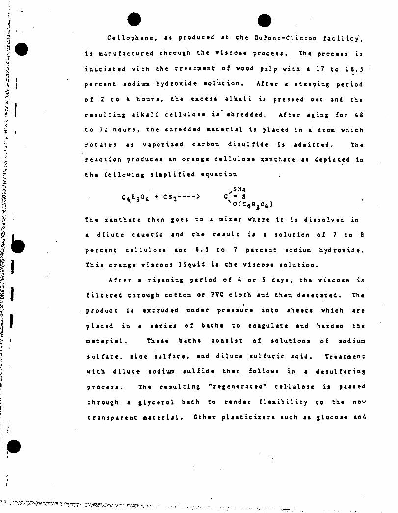
Cellophane, as produced it the DuPont-Ciinton facility',
is manufactured through the viscose process. The process is
initiated with the treatment of wood pulp with a 17 to 18.5
percent sodium hydroxide solution. After a steeping period
of 2 to 4 hours, the excess alkali is pressed out and the
resulting alkali cellulose is shredded. After aging for 48
to 72 hours, the shredded material is placed in a drum which
rocates as vaporized carbon disulfide is admitted. The
reaction produces an orange cellulose xanthate as depicted in
the following simplified equation
,SNa > C - S
vo(c6h,o4)
The xanthate then goes to a mixer where it is dissolved in
a dilute caustic and the result is a solution of 7 to 8
percent cellulose and 6.5 to 7 percent sodium hydroxide.
This orange viscous liquid is the viscose solution.
After a ripening period of 4 or 5 days, the viscose is
filtered through cotton or ?VC cloth and then deaerated. The
product is extruded under pressure into sheets which are
placed in a series of baths to coagulate and harden the
material. These baths consist of solutions of sodium
sulfate, zinc sulfate, and dilute sulfuric acid. Treatment
with dilute sodium sulfide then follows in a desulfuring
process. The resulting "regenerated" cellulose is passed
through a glycerol bath to render flexibility to the now
transparent material.
C6H9°4 ♦ CS2----
'-o-s-r:
Other plasticizers such as glucose and
polyhydroxy Alcohols may be substituted for Che glycerol in
che -softening phase of Che process.
Once che cellophane is washed and dried, various
addicives may be applied Co imparc specific qualicies co che
final produce. Moiscure proofing is accomplished with a
solution of low viscosity cellulose nitrate, plasticizers
such as dibueyl phchalace or cricresyl phosphate, phenolic
resins or alkyd resins of glycerin and phthalic anhydrides,
and waxes such as paraffin or ceresin, all dissolved in a
mixture of volatile organic solvents. Alternately, vapor
transmission may be lowered by eoacing ehe cellophane wich a
polyvinylidene chloride latex. Flame resiscanc addicives are
generally phosphates and chlorinated hydrocarbons.
Source: Proposed Activities for the Site Investigation of theLawrence Todtz Farm Site, Camanche, Iowa, TDD # R-07- 8402-17A, August 20, 1984, Region VII REM/FIT.
f

FEED STOCKS AND WASTE PRODUCTS ASSOCIATED WITH
Source:
:wJ35S?yS'
THE MANUFACTURING OF CELLOPHANE
Letter to Nancy J. Johnson, USEPA Region VII from D. P. Du Vail, Senior Engineer E. I. DuPont de Nemours and Co. dated August 25, 1986.
i
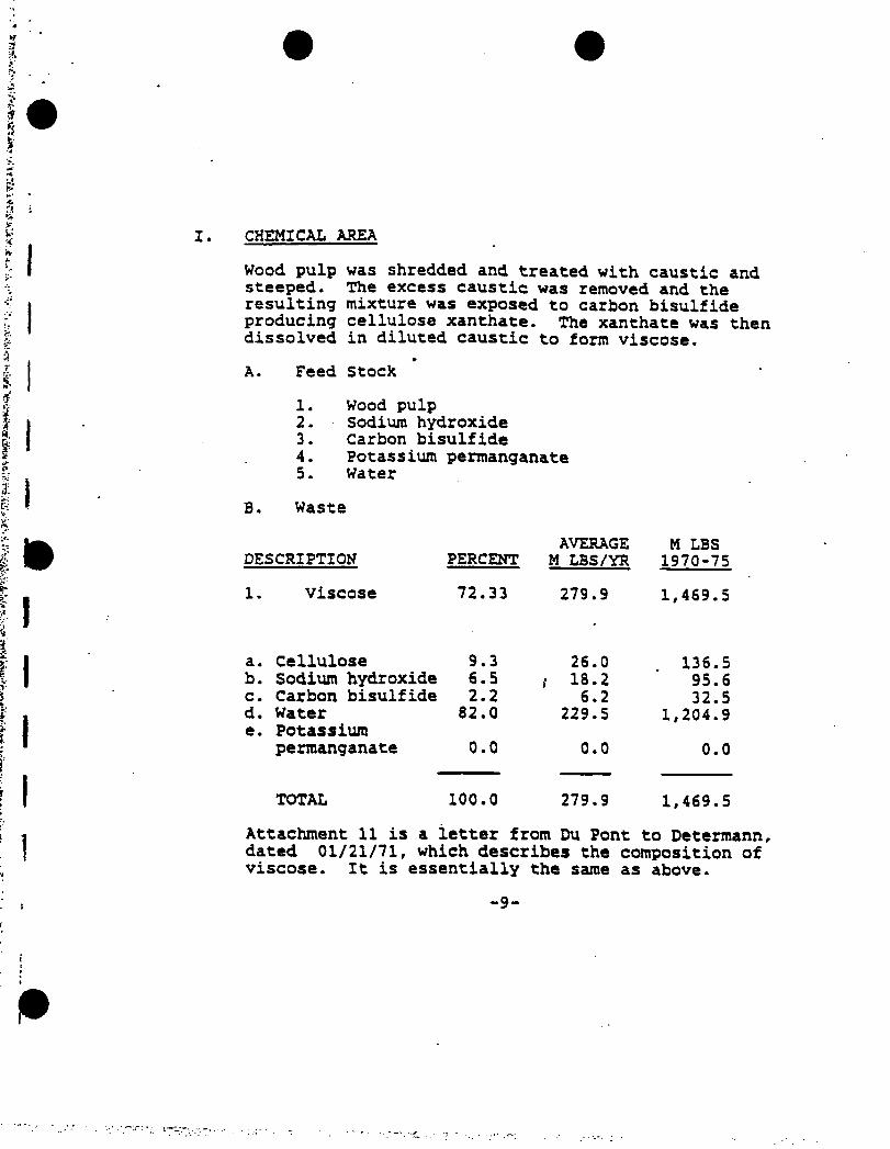
I. CHEMICAL AREA
Wood pulp was shredded and treated with caustic and steeped. The excess caustic was removed and the resulting mixture was exposed to carbon bisulfide producing cellulose xanthate. The xanthate was then dissolved in diluted caustic to form viscose.
»A. Feed Stock
1. Wood pulp2. Sodium hydroxide3. Carbon bisulfide4. Potassium permanganate5. Water
B. Waste
DESCRIPTION PERCENTAVERAGE
M LBS/YRM LBS 1970-75
1. Viscose 72.33 279.9 1,469.5
a. Cellulose 9.3 26.0 136.5b. Sodium hydroxide 6.5 i 18.2 95.6c. Carbon bisulfide 2.2 6.2 32.5d. Watere. Potassium
82.0 229.5 1,204.9
permanganate
o•o
o • o
°.
o
1
TOTAL 100.0 279.9 1,469.5
Attachment 11 is a ietter from Du Pont to Determann, dated 01/21/71, which describes the composition of viscose. It is essentially the same as above.
-9-
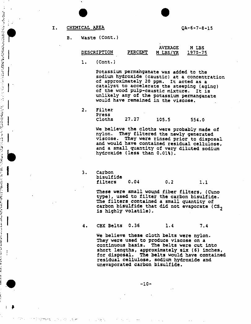
I. CHEMICAL AREA QA-6-7-8-15
B. Waste (Cont.)
DESCRIPTIONAVERAGE M LBS
PERCENT M LBS/YR 1970-75
2.
3.
(Cont.)
Potassium permanganate was added to the sodium hydroxide (caustic) at a concentration of approximately 20 ppm. It acted as a catalyst to accelerate the steeping (aging) of the wood pulp-caustic mixture. It is unlikely any of the potassium permanganate would have remained in the viscose.
FilterPressCloths 27.27 105.5 554.0
We believe the cloths were probably made of nylon. They filtered the newly generated viscose. They were rinsed prior to disposal and would have contained residual cellulose, and a small quantity of very diluted sodium hydroxide (less than 0.01%).
Carbonbisulfidefilters 0.04 0.2 1.1
These were small wou*id fiber filters, (Cuno type), used to filter the carbon bisulfide. The filters contained a small quantity of carbon bisulfide that did not evaporate (CS- is highly volatile). 1
CBX Belts 0.36 1.4 7.4
We believe these cloth belts were nylon.They were used to produce viscose on a continuous basis. The belts were cut into short lengths, approximately six (6) inches, for disposal. The belts would have contained residual cellulose, sodium hydroxide and unevaporated carbon bisulfide.
-10-
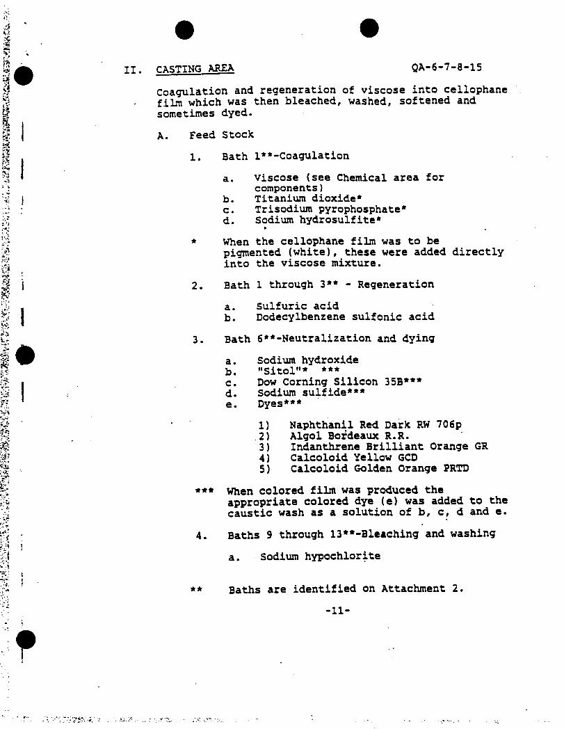
II. CASTING AREA QA-6-7-8-15
Coagulation and regeneration of viscose into cellophane film which was then bleached, washed, softened and sometimes dyed.
A. Feed Stock
1. Bath l**-Coagulation
a. Viscose (see Chemical area for components)
b. Titanium dioxide*c. Trisodium pyrophosphate*d. Sodium hydrosulfite*
*
* When the cellophane film was to bepigmented (white), these were added directly into the viscose mixture.
2. Bath 1 through 3** - Regeneration
a. Sulfuric acidb. Dodecylbenzene sulfonic acid
3. Bath 6 ^-Neutralization and dying
a. Sodium hydroxideb. "Sitol"* ***c. Dow Corning Silicon 35B***d. Sodium sulfide***e. Dyes***
1) Naphthanil Red Dark RW 706p2) Algol Bordeaux R.R.3) Indanthrene Brilliant Orange GR4) Calcoloid Yellow GCD5) Calcoloid Golden Orange PRTD
*** When colored film was produced theappropriate colored dye (e) was added to the caustic wash as a solution of b, c, d and e.
4. Baths 9 through 13**-Bleaching and washing
a. Sodium hypochlorite
** Baths are identified on Attachment 2.
-11-
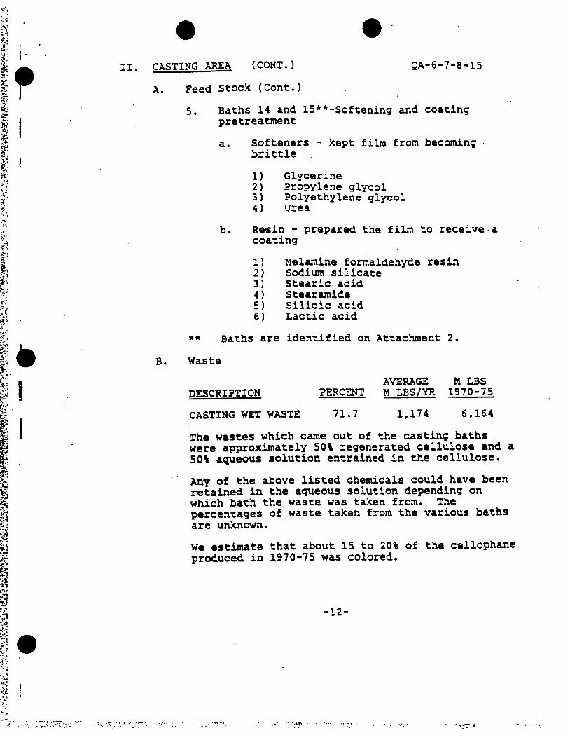
II. CASTING AREA (CONT.) QA-6-7-8-15
A. Feed Stock (Cont.)
5. Baths 14 and 15**-Softening and coating pretreatment
a. Softeners - kept film from becoming brittle
1) Glycerine2) Propylene glycol3) Polyethylene glycol4) Urea
b. Resin - prepared the film to receive a coating
1) Melamine formaldehyde resin2) Sodium silicate3) Stearic acid4) Stearamide5) Silicic acid6) Lactic acid
** Baths are identified on Attachment 2.
B. Waste
AVERAGE M LBSDESCRIPTION PERCENT M LBS/YR 1970-75
CASTING WET WASTE 71.7 1,174 6,164
The wastes which came out of the casting baths were approximately 50% regenerated cellulose and a 50% aqueous solution entrained in the cellulose.
Any of the above listed chemicals could have been retained in the aqueous solution depending on which bath the waste was taken from. The percentages of waste taken from the various baths are unknown.
We estimate that about 15 to 20% of the cellophane produced in 1970-75 was colored.
-12-

QA-6-7-8-15
III. COATING AREA
Applying various coatings to dry film.
A. Feed Stock
PERCENT OF COATING BATHAVERAGE AVERAGE
NITROCELLULOSE OTHERINGREDIENT BATHS BATH
1. Nitrocellulose 40.52. Toluene 27.6 20.2 ‘3. Tetrahydrofuran 22.3 59.74. Saran resin - 19.55. Dibutyl Phthalate
(Phanex-1) 2.7 -
6. Dicyclohexyl Phthalate(Phanex-4) 2.7 -
7. Petrex 1.5 -
8. Bentonite (Slipex) 0.1 -
9. Poly-pale 0.8 -
10. Beckacite 1.3 0.0611. Aristowax 0.5 -
12. Carnauba wax - 0.1013. Candelilla wax - 0.1414. "Arquad"* - 0.1215. Talc - 0.0916. Maleic anhydride - 0.0517. Calcium oxide * 0.04
TOTAL
i
100.0 100.0
The following ingrediens were used in other than nitrocellulose coating baths with an approximate ratio of less than 0.20% of the bath:
18. Tetra wax19. "Duponol"*20. Santicizer21. Behenic acid
The following ingredients were used to dissolve some of the above compounds before putting them into the coating bath. The percentage used is unknown.
22. Isopropanol23. Butylated hydroxy toluene24. Butyl acetate
:w ■ ■
-13-

QA-6-7-8-15III. COATING AREA (CONT.)
B. Waste
DESCRIPTION PERCENT
Coating wetwaste 4.7
AVERAGE M LBSM LBS/YR 1970-75
77 404
During the period 1970-75 it is estimated that approximately 20-30% of the cellophane produced had'a nitrocellulose type coating. All other films had a non nitrocellulose (other) type coating.
All of the feed stocks, except for 2, 3, 22, 23 and 24, to some extent, became a part of the coating on the surface of cellophane. Once dried the film coating was approximately 8% by weight of the film.
Ingredients 2, 3, 22, 23 and 24 were solvents used to carry the solids in the coating bath onto the film. These were recovered and reused or if not reusable, were disposed of through the plant water effluent system.
The wet coated film waste is estimated to be 80% cellulose and 20% solvents and coating solids. The solvents were quite volatile and most likely would have evaporated from the wet coated film before reaching the landfill. f
Attachment 2.
REM II Groundwater Data
»
'VSV,,

j
d
IABLE IEROUNONAIER DUAL I IT • Aiulyltctl Rtiulls lor Mooilorio' Hell SioylM (Or'inic Coopouodtl ICootcM/oliooi nprtwi if uy/1)
FILE HUE: KHORESM l7No«-B7
ROHITORINfi HELL M1II8ER »> NH-I NN-7
USER* SANPIE HUMBER •> BKJI7037 J0717001 J1717001 J27I700I J47I700I BXJI7057 10717007 J1917002 J7717002 J4917002SAMPLE ROUMB HUMBER •> l 7 3 4 S 1 7 3 4 3
SAMPLE BAIE •> OCt BE NOV ‘BE FEI 17 IIAf '87 AUS ‘87 0C1 '84 NOV ‘8E FEB ‘87 MAY ‘87 AUE ‘87
VOUIILE 08EANICS:
Cirboo Bitolfidc Actloor2- BulinoM Inmi lolatocHclbyltnt Chloride
ItlrthydrolarMCklorobnrtotChloroclktof1,1-ticklwOttktMHrlkrl'F-FialnwiCklortloroInchlorotlktot
Ethyl ktinrlyltitl llotill7-PraptntlhiolBicbloratrilleorotolatet
Hcitwthyl CyclolriiilMMtl-lthyor-Bitm3- Htlkyl-2-letuoof
4.8 K
1.8 II3.2 N
II. 0 10.0
o.F n
t.o l •
BASE/NEU1RAL/ACIIEllRACriBLC OMEAMICSt
Pfctaol7-Htlkylykmol4-Hrtlkf Ifktaal
. 2,4-OieclhylfbroolB«aiyl AlcoholPtoilfklorspEfOol2,4-0ichloroph«ielHribylbMitototlhiaol2,5,8,II,U-PMlkon-
HtndtCM-IE-ol 214.0 1
7,3,8,11,14-PmUoio- ProUdrcu-li-ol
7,7-17-Ntlhoiytlhoiy)Ctkoiy-Ethoaol 717.0 J
2,3,0,11,11-Pralroiy-Ptaltdtciat 40.0 J
2-Elhaiyll-Htlhoiyl*•throe 24.0 1
5-Hclhyl-l,l-Hri<dint 70.0 2
1,1,5,1,9-ffaUlkininf1,2,4-lrilEioljeel,2,4,E-lelr*lhieptne
3.1 H

&
TiV-.t
;5T:«•
vi*;
HIE DUE: HN0B6MI ll-Ko*-B7
lULi ISROUMOMIEO BUM.III - Aiwlytical Rtiulll lor HMitoring Boll Sup I it (Orpine Coapauadil ICoottolroliooi ripnisid is up/ll
$ MMIIOBINS KILL MJIUER •> NH'I MI-2
USEFA SAHHC MUftKCb *> BHJI7057 MI1700I J111)001 J2H700I jmiuoi BtJ1)032 Ml 17002 JIII70U2 3211)002 34117002•• .v* SAHPIE ROOM MMBft ») 1 2 ] « s 1 2 I i 3
sahfle o»ie ■> OCI ‘10 NOV ‘00 FEI ‘07 MY ‘87 MIC -07 OCI ‘00 NOV ‘00 FEB 07 HAY ‘17 AUB ‘87
l,Jl3,7-lttritbiacifti1.3.3- Irilkitot1- C|(ltktito-l-»l,2,0-
OiMlkplicititiNiphlhiltat
Ocaioic kid FiaIiaoic kid Htiiasic kid Octiaoic kid Bcciifir kid ItlridKiAoic kid Htudcciioic kid Fbnylpftfutdioc kid biinipri|iiiK kid Itoiootutlu kid 3-Httkplbtdiiic kid Y-Kflkplktiuic kid2- Httkpl-FtAliAoic kid3- Hrtkpl FmiIiaoic kid 2-Ntlfcylkfiiioic kid2.3- DlMtkrl-iMMOC-
kuliAoic kid ttatui kid,),5-Bit 11,1-OiMtkplilkylM-Hr Hydroiputkaip
kMiildiOydc 2-lhuioliditilkio<( Holicalir Sailor FalytUyltAt tlycsl
laoMlkylttktrOiitlkyllrittai1.4- BiutkylhnuAt 1,3,5- Iriattkylkicyclo-
(2.2.l)ktplia-2-oat ♦-12.0.0-lrmlfcyl-l-
tytlokn*A-l-yll-3-
kolu-2-CMt N.N-litU-Xydrtiyttkyll
Iodic 1(1dt Bit-17-Elklylktiyll
FMbiltlfICyflohntAi-l-HelhlAol,
Alphi,Alpki-(-lk «-llkrl -l-llrlhyl ItKttie-
Salluaioilt
l.l II
20.01.0
720.0 J
II
10.0 j

• 'V’ >*. ... . ;• <*• w : V' * w*
■«;,1
8
rili NMf: RNOKMf i«-Mo«-ir
TAME ISMUUNA7E8 OUAlllY - AAilylml Ittullt lor Monitoring Hell Sioyltt (Orgiiiii Conpoultl IConctolntioot tiyrttttl it u|/ll
t MMIIOIlNt veil MUItOEk •> NM HH-2
O USEPI Slim NtJHBEI «> BKJ17037 J01I700I 1 HI 7001 J291700I Jill 7001 BIJI70S2 J0YI7002 Jill 7002 12VI7002 J44I7002
h‘< sum R0UN0 NUIIfl »> 1 2 J 4 3 1 2 1 4 3SAMPLE 0AIE »> 0CI li NOV 'll FEB '17 DM ‘17 MIC '17 0CI ‘11 NOV ‘11 FEB 17 MY ‘17 MIC ‘87
IkitiilIC fell Htulkitym Hey tunic tell Bittkylyklkilit* lutyl Itniyl Pktkilit*01- N-Oclyl Pktkilit*Bi -N-Butylgklkilit*
• Btimoiulloiuilt, 11,11, t-lriwlkyl
Hrlklnt, lutkiocyinotl2- tntuiu, 1-IWUyl 2-P(ituoot, 4-Myloiy-4-
Hcthylli eye 1 o( 2.2.11 H*ytn-2-
Mt, 1,7,7-lriMtkyl
PfSriCllfSlAroclor-1234
0.2 N
0.1 It It
2.0 R
11.0 N801.0 H
ie.o i 21.0 J
NOUS:I. Itlrihylrolurii kit krtfl iltnliliri if * ceailituNt. Hon* *tf,
(MfMlntiMt if* Mly rtliiklt li dm tigiiliciol ligur* kteutt ka rtItrMCi ttulirl Mt uttd lor guMtitltio*.
Kf INIlllHSiR - CouetntriliM it kflou guuti licit im lltlt IIISEPAI
or lut tkii (Mtrict rtgoirtl IiIiiIim luilt tQ.PI.J • Cooyowl uit guililitiotly iliililidt koutvoe, cooyouid
lull! ti itcl ill M critofii Ml it tkirilsr* uly u tit lolled mitt.
ri
'1

• ■»•*1 .. .v -
FILE RARE! RRORCDAt lf-kav-07
1AHE I6AOUNOBA1ER HUM.)TV - Anilyticil Retails lor Renitarinq Veil Saaplti lOrymic Ceapetiads)
ICeactalrtliaM tipressed <t u|/ll
1
Ethyl koiMtlyltaal IWlil)I-Fr^uilkliltickler alMlIaaratalataoHeiiectkyl Cyclelritileiut
l-Elkyai-taliie3-Hatkyl-Mol mono
ft
3.374.0
ROHIIOklNB VEIL NUIUCR *> AH-3 RR-4
USER! SARPIE RIMER •) H7I7054 JOf17003 J1917000 J2917003 34917003 81 J! 7055 J0917004 31917007 32917004 34917004
SARPIE I0UN1 RURkfl *> 1 2 3 4 5 1 2 J 4 3
SARftE DATE •> 0CI 'li ROV 'BO FEB B7 RAY B7 AUS 87 on -to NOV '00 FEO '67 NAY ‘B7 AUS '67
VOtAlllE WSAAICS:Cirbofl linllid* 2100.0 3000.0 ffO.O 300 31.0 J 2.0 R 17 R
Act toot 470 7
2-OuluoaaItaiaat 0.1 N II.0 22 R B.i
lolutat 100.0 R 7.0 H 33 RHelkyitat Cklaridt 290.0 010.0 j 0.0 B3 R
Ftlrakydrelaru 1200.0 7 180.0 J 110.0 13000.0 J 19310.0 7 15000.0 5900.0 7 170.1
CklarakmwtCkloreclkiot1,1-Oickliraatktai 0.0 H
4-Hat kyl -2-Pnl Meat 10.0
Ckleralara 18 R
trickierealktat If N
7.» J
MSE/NEIIIRAl/ACIO ElIRtCIAHC ORCMICSi
Pkeeol 74.0 7 130.0 3 37
7-Htlkylpktoel 9.7 H 7.4 H
4-Relkylpktflol 120.0 7 Itt.t 7 40.0 77
7,4-tiMlkylpkcaallaaiyl Alcafcal 4.7 N
ftalicklerapkcaal2.4- Dicklerapktaal
RtlkylktoiMMilkMol7.3.1.11.14- Ptalieii-
HtiidtCM-IO-el2,3,8,11, I4-Pral*eu-
fralidecM-IO-al
2,2-17-Netkeiyatkoiyl Etkeiy-Elkaael
7.5.1.11.14- fe*Ueiy- PtaltdKtat
2- llkaiy-ll-Rrtkaiyl-tlktat
3- HflkyJ-l,4-Hri<dir«r lil|3,7,9'P»*l*IRm»»*1.7.4- lrilkielMt 1,7,4,0-lttrilkitpMt
230.0
100.0
9332.0 J F03k.t J tull.t J
2000.1 J
13.0 J
132.0 J
411.0 J
1200.0
200.0

FILE NAMi HHOftBDAI IO-Nov'87
lAfclC I
GROUNONAIEt BUM. 1 IT - Analytical final ts I of Hoailarinj Nell Sup Id I Ornate Caapouadil IConcealraliont tipreitrd at uf/lI
MINI 10ftIMG MU MIAMI •> NN-3 MN-4
u$fp« sum mat •> UJ17034 J06H003 J1011004 22012063 J4017003 M2J10S5 20012001 2)011001 22011004 24011004
SAAM 80UND NUAMk •> 1 2 3 4 3 1 2 3 4 3
SAAHf tkl[ » 0£I '84 NOV '84 FEB ‘87 DAO ‘81 AUG 'll 0C1 '84 NOV '84 ffk ‘87 AA1 87 AUG '81
1,3,3,1-ltlralbiscane 2032.0 J
1,3,3-lritbiaar l-Cyclokifia-l-ol,2,4-
004.0 J 210.0
Oiaelbylacetitf 412.0 J
Njpklkiltot
keaapklbyleae keaioic kid keataaaic kidHeiiaaic kidOcleaeic kid 130.0 J
04.0 H
310.0
340 i
830.0
Oecaaaic kid 44.0 l 140.0 210.0
letradKaaoic Acid Heiadecaaaic AcidFkrnylpropaaidioc kid 306.0 1leaieatprapaiiac kid 110.6 ileaiiBctcilK kid3- Aelhylkeaiaic kid4- Hethylkiaioic kid2- Aetkyl-Peataaaic kid3- Helhyl Peataaoic kid 2-NtUylktiaaaic kid2.3- liatlkyl-leaieat-
Oulaaoic kid ktaioif kid,3,3-lit ii,i-Diwtkriiibriii-Hr
Hydroiyatlkaiy-ktnialdtkyde 40.0 I
2-lkieielidiaeiAiaaf 43.0 JDolecaUr Sailer 1000.0 1polytikyltae Glycol
Nonoalkyltlker 211.0 J
liatlkylktaitet l,4'0lMlk|lkcaieai1.3.3- lriatlkylbicyclo-
f7.7.l)brftaa-7-aar4- 12.1.4-lrinelhyl-l-
eye liili*iea-l-fll-J- kutea-2-oae
N,N-biil2-Nydroiyflhyll
Oodetiiide Nii-ll-Elklylhtirll
I'AIAalatr5- Cyclokfitnt-l-krthaael,
Alpha,Alpae-l-lk
N llkyl 4 Itfliiil b»a:re»- baltOHaaidi
321.0 J
1112.0 J
10.0 J
01.013.3 J
8.3 J
14.0 J
libO.O J
174.0 J 11.0 J
17.8 J
14.0 J
2.1 N
20.0 J
4.0 N
20.0 j

H Mt'li
$
lAklE I6R0UMMIEI OtlALIfV - Anilyticil Result! lor Itomtorinq Veil Sup let (Oryiaic Coepouaitl
ICoociatritiont eipretsed K u|/ll
FILE NAME: NV0R00AI 11-Nov-BI
MVII0IIVE VEIL NUMBER •> MV-J NN-4
USFPd SAMPLE NUHBER >) BY2I7054 J0117003 21117001 J21I700J 24117003 Bill 7055 20117004 21111007 22117004 24117004
SAIPIE ROUNB NUMBER •) 1 2 3 4 3 1 2 3 4 3
SAMPLE 1A1E •> OCI 'Bt NOV ‘BS FEB B7 Ml B7 AUt 07 OCI ‘Bk NOV ‘Bk FEB B7 NAY 8? AIK B7
Butiaou Acid Heiithiepiae Hcpttooic Acid Oiethylpklkilale lulyl Besiyl Pklktlite
Bi-N-Odyl Pklkilite Si-N-l«t|rlfMliil<te Bcaiesttullaataidt, 11,11,
4-lriaelkylHctkioe, Isethiscyisots2-Pcatiseae, 3-Nctkyl
2-Ptalinutt, 4-Hydoey-4- Relbyl
Bicydel2.2.ll Heplia-2-
M>, 1,7,7-lnsetkyl
200.0 230.0 j10.0 J
II.0 J
27.0 J14.0 J
73.0 j
pesiicibesi
Ar odor-1254
MOIESlI. letrihydrefurM hit keen idestilisd es i rootlilsul. Veuevrr,
csacentritiesi ire osly reliiblf towie tiyailiciol liyure keciute os refertoct iliilul on used lor quiitititios.
OEFIMITimSt
M - Cooceotrelieo It kelon ysiitilicitios lisit (USEPA) or lets Ikes cootred required detectisa litiii ICLPI.
2 - Ceapouad on ysilitilively ideolilicdi however, couponed lilted to seel ill M crilerii tsd It Ikerelsre osly in
etlisiled vtlse.
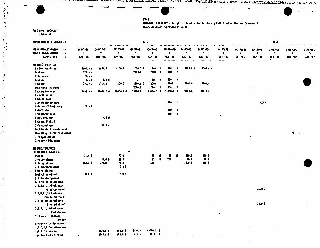
# 7 ' " *
■ - ---- - - - - - - - - - - -* . 'IAILE 1SMMMONAIER 0UALI1Y - Aailytiul Briults lor Hoailoriay NrII Saaylti (Orginic toipogndi)
FILE RAAEi HHOKOAll9-No*-S7
MWIlUine BILL MJJIBEI •> NH-5 HH-k
user* SAMPLE UMBER •> 1X717031 J0917005 709170031 71917001 32917005 329170050 30917005 319170050 IK3I70S3 IH3I70530 3091700k 31917003 37917001 30917001
sum ROUND NUABEI » 1 2 2 3 1 0 3 3 1 1 2 3 0 5SAMPLE 0A1E *) DC1 ‘Ik NOV 'Ik NOV ‘Ik FEB ‘17 RA9 ‘17 HAf 17 AIK ‘17 AUB ‘07 Otl ‘Ik 0C1 0k NOV ‘Ik FCI |I7 HAY 17 MIS ‘87
VOU1IIE ORSMICSlCirbaa hull lie IDM.D 1 IkOO.O 1100.0 390.0 3 1700 N 010 N 1000.0 3 3300.0 3kitMt 27#.0 1 7000.0 7500 J 110 H
2-luWioiit 75.0 3biim 9.3 R 3.0 H 91 R 320 N AIlluMIt 700.0 J 1700.0 1100.0 1000.0 3 7300 2000 IBOO.O 8000.0
Methylrar CkloriNt 2300.0 700 R 310 RIrtrikydrilvrMCklarokrattat
2100.0 J 20000.0 3 10310.0 3 23000.0 01000.0 7 30000.0 3 97000.0 90000.0
Cblorsrlkiac1,1-Oifklerarlkrar 100 ' N 0.3 RO-Htlkyl-7'PtnUaoatCkloroicr*
21.0 R100 N
IricklsrMlkrit 310 HEthyl Iraitet 0.3 Rl|luti Hotel 17-Prtfiatlkiol Dichltralriilusr.lolrrit HtitMlkrl Cydolriiiloiiar l-[|k|rw'blut J-Htlkirl-2'ktUMi
30.0 J
20 3
USE/MEUTBH./ACIDEI1AACIAILE OREANICSi
Pknsl 31.0 1 72.0 91 I BO H IIO.I 190.02-RtOkylykraol II.0 H 11.0 13 R 220 00.0 40.tt-klkylpknol 130.0 1 320.0 170.0 lit 1000.02,4-liMlkrlyktael 2.k RBtaiyl AlcaktlPtatublorafktaal7,0-ticbloroyhtaalHttbylbiaitaratthtael7,3,8,11,10-PmIum-
31.0 R 13.0 H
HllltKM'li'll 30.0 3
2,3,1,11,10-PmIiru-Praliitda-ll-.l
2,2'12-Httkoiyilkoiyl30.0 7EtboiyEtkiiol
2,5,8,11,H-PiaUoirPratiBmat
I-Elhoay-tl'Methoayl-itkmt
3-Metbyl-l,8-HraarftrntI,1,S,),Hi>IiIIuk im |,],t-lrilkieltat 2170.0 J 102.0 J 7100.0 I000O.0 J
1,2,4,6-latrelhiepene 1700.0 i 190.0 3 Oktl.O 10.0 j

FILE HUEi NMORSBAT
l4-Nov-B7
‘ y*.vv“:.v,-.. At-fiattvVanuimvsu,
HUE IShOUMCHAIER OUALIIV - Aailylicil kttulli I Of Roiilorinq Well Suplis IQfyimc CoipDundtl
(ConccfilntiBM t<prti»d as ua/ll
MWIIOIINE KEEL MIH8ER «» IW-5 MH-4
USEPA SAMPLE NUMBER »> K317054 30417003 J04I70030 3I4I700B J2417003 324170050 J4417005 J44I70O3B BY3I70S3 BLJII03I0 J04I7004 J1417003 J74I7004 J4417004
SAMPLE ROUND NUMBER *) 1 2 2 3 4 4 3 5 1 1 2 3 4 3
SAMPLE BAIE «) OCI ‘14 NOV ‘14 NOV ‘04 FED '07 NA! ‘07 MAY ‘07 ADO ‘07 AUS ‘07 OCI '04 OCI ‘04 NOV ‘04 FEB B> MAY ‘87 AUS 07
1,1,5,7-lttrathiocaiit1,3,3-lrilkiaorl-Cycloktita-l'01,2,4*
BiMtkylacatatr
1710.0 3
Btaraic Acid,3,3-Bii11.1- Biatlky)flky))4-My
Hydraiyttlkaiyktaialdtkydt
2- 1kiatalldiatlkiaaaHalicalor Sulfur 710.0 J
Palytlkyltat SlycolHMMlkylcUcr 3S.0 J
OiaalbylkMita*
1,4-OiactkylkMicac1.3.1- Iriaalkylkiiycla-
(2.7.llk»p(aa-2-e«t4-17.4.4-lriaalkyM-
cyclafctiM-l-yil-3*
kulH-7-oot
N.N-OiiU-HydraiyilkyllDadtcaaidr 100.0 J
lit'17-ElklylhtiyllPklbalale 4.7 II
3- Cyc I oktiM»*l-Hrlboaol,
Alpka,Alpka-4-lk M-It kyl-4‘Hrlhyl*ltoi(R(*
Sullaaaaidt
330.0 j443.0 H 100.0
NapMhaltaa
AcMapktkylcai
7.3 H
Btateic Acid 770.0 70.0 1
Pcataaaic Acid 41.0 J 140.0 3 410.0
Htiaaeic AcidOclaaeic AcidOccaaoic AcidIctradicaaaic Acid
HtlidtCUSIC Acid
340.0 J240.0 3
Pfcaaylprapaaadiac Acid Btaitatprapaiiec Acid 700.0 3 1120.0 3 170.0
OtkiMiuttic Acid 44.0 i 340.0 J 440.0 3 130.0
3- HclkylkniBic Acid4- Mtlkylknioic Acid 7'Htlbyl-PMluoic Acid
3-HtLfcyl Pcflliuic Acid 2-NtlkylktiMaic Acid
7,3-Biatlkyl-BtAitRt-
37.0 3
340.0 J
244.0 3
170.0
Ruliisic Acid 320.0 J 172.0 3 —
300.0 J 1000.0 J
370.0 J 340.0 J
340.0 J
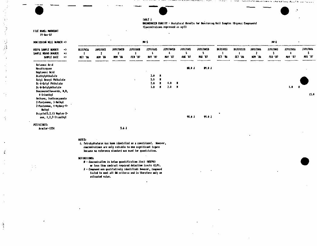
(MIC ISkQUNSHAIEN lUAlllY - Aotlyhrtl Afiulti lor Noaitorioq Doll Sitpltl IDrqinic Coopoiiiidtl ICoacrntritiooi tiprtsstd n ug/ll
HU NINE: ANOR60AI
IO-Nov-17
N0NI10RINE Mil MJHBER •> IM S NN-i
USEPA SANPIE NUMER >) li'J17051 JOTI1005 JOVI70051 JI9I700B J7YI7005 J70I7005D J4TI700S J4TI70050 SRJI7051 1KJI7053D JOT17001 JIYI700I J7TI7001 J4YI700S
SANPIE ROUU NUNREI »> 1 J 7 ] t 4 5 5 1 1 I I 4 5
SANPIE HIE »> Ml U NOV 11 NOV ‘11 fit '17 NAT ‘17 NAT ‘17 AUS ‘17 AUS '17 OCT ’ll 0C7 ‘IS NOV ‘11 fit -‘17 NAY ‘17 AU6 ‘17
lutiooic And
HtnthitpiiiHtptiooic Acidliflkylpltkilitr 1.0 N
lutyl Itnyl Pktbaltie 1.0 N
li-N-Octyl Pktkilito 7.0 N 4.0 N
li-N-lolylphthilito
Itiuntiollooioidt, N,N,
1.0 N 7.0 N
4-lriatlkyl
Httkinr, luthiocyiooto 7-PtoWoont, ]-Ntlkyl HnllMM, 4-Hydoiy-4-
Htlkyllicyclol7.7.l) Htplio-7-
oio, 1,7,7-Iriottkyl «.0 1 M.O J
PESIICUES:Ar oc I or -1734 5.1 J
15.0
MUSi
I. Ittrifcydrafurio kit IfM idntilied it i CMilitoeot. Hoottrtr, caoctatritioot u( only rtliiblt to oat ngoiliciot I Hurt ktciott to rtltrtoco ttudird oil otrd lor quiotititioa.
KFimilMSiN - CoorMlntfoo it ktiao goiotilirilioo lioil IU5EPA)
or Ittt tkio coalnct rtqoirtd dtticlioo lioitt ICIPI.J - Coopauod on guliUtivcIy idttlilitdi kootvtr, coopouod
failed to wtt ill U criltril aod It Iktrtlort oily io litioittd vilut.

■S'W re>;..V:--^
IMIC 2
EROUNOMAICR SUM IIY - Aaalylacal Rtsulli lor lla* it on if Hell Saapln Hneryaaac Coapotiaii) ICoacrntratioai la ay/11
rill NAME: MH1N0KDAT IO-Nov-87
MONITORING BELL MURRER •) IIM-I HM-2
IISEPA SAMPLE NUMBER •> BIJ17037 30017001 J19I700I J70J700I J4RI700I 68317052 JO9I70O? JI0I7002 37017002 J 4917002
SAMPLE ROUNO NUMBER •) 1 2 ) 4 S 1 2 1 4 S
SAMPLE DALE >) OCR 'BA MOV 'BA FEB '87 NAY 'B7 AUi 17 OCT BA NOV BA FEB '07 NAY '07 AUS 17
metals:Alaaiaaa 100 48 30 4A 22 43 44 14 3.A 2.6
Aatiaoay
ArttaiiBariaa B.AA 0.73 0.21 0.37 0.17 0.77 O.OB 0.31 0.33 0.47
Berylliua 0.007 N 0.007 N
Cadaiaa 0.0IB 0.03B
Calciua 320 770 710 100 0.14 710 J 730 170 140 0.14
Ckraaiaa 0.19 0.11 0.11 0.007 1 0.033 0.1 0.14 O.OB4 0.071 J 0.023
CaAill 0.1 0.013 M 0.071 O.OIA N 0.030 0.082 0.074 0.013 H
CstyK 0.13 0.006 0.0A3 0.070 0.03 0.000 0.14 0.043 O.OIA if 0.013
Ira* 120 37 43 47 J 73 7B 100 44 44 J 31
ItaM 0.03 0.072 0.044 0.37 0.031
Ha|arsiua 170 no HO no 0.073 BA J 00 68 33 0.033
IUi|iuu 2.7 1.2 0.04 O.BA 0.40 A.B 8.7 71 1.3 l.l
Ntrcary 0.0004 3
Aolybdrnua 0.013 0.010
Mittal 0.17 0.1 0.11 0.072 .0.048 0.12 0.71 O.OBA 0.033 0.036
Potanina f.S 3.3 R 4.3 3.4 N M/A 14 17 N IB 13 M/A
SaimaaSilver 0.012 0.006 A
SaBiaa 13 12 77 B.B 1 14 43 31 37 36 J 44
Tilaaiaa 0.30 0.3 0.4A 0.003
Vaaadiaa 0.0A7 0.17 0.0B8 0.1 0.03 0.14 0.040 0.014
liac 0.27 0.14 O.OOA 0.1 0.003 0.23 0.23 0.083 0.03
MOM-METALS:Alkaliaity-total 1060 J 267 333 733 171 633 647 374 618 383
Chloride 77 17 17 10.8 14 73 ft 13 13.6 14
'Nitrate 3.V 3.1 3.1 II.2 32.8 3.1 0.0 1.66 7. OB
Sul(at* 33 33.0 48 I07.A 76 7 II. * 1.0 71.3 3
Sal 1iMr 0.B04
f 1(11 PARAMETERS: leeperatare ICelilvil 17.3 II.3 0.1 13 IS 17.0 0.0 17.3 16.3' 17.3
Saliaity (O/OOIppa B.73 0.3 0.73 0 0 0.3 0.73 0.3 0.3 0Ceadailmly laaAatl 300 433 440 460 4B0 oeo 000 810 830 010pH lilt an11a 1 6.6 A.B 7.3 3.B 7.1 6.4 6.3 6.6 6.0 M/A
6ratiaA Matrr tin. BI.3 70.7 70.4 70.4 7B.4 72.0 70.7 68.7 66.0 68.3
(rplk to Matrr till 13.80 17.40 17.60 17.7 IB.7 17.62 70.37 . 71.B3 73.6 71.07
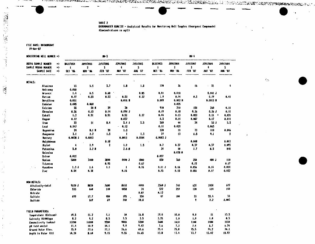
»>••*>•*£ •'ft\«tV./i$.A:SsV''i; J, .h
iaiie 7EftOUNOHAItR OIMltlY - Analytical Otiulll lor Nonitoriaq Noll Saaplti lloorqanic Coepotindjl
(Coactolralions 11 op/11
rilt NUIfi HHINQAfOAI
ll-Nov-8?
MNIIDHNG HELL MUniCR *> IM-] HH-4
USEPA SAMPLE NUM8EI •) 81JI7034 J04I7A03 jnntti J2117003 Jlllfttl BKJI705S JOf11004 J1117007 J7117004 J41I7004SAMPLE AHUM RUMIEN •> 1 7 3 4 5 1 7 3 4 3
SAMPLE DAIE •> KI 'BA NOV 'BA fEI '87 NAf '87 DUE 87 OCI 'll NOV 81 FEB '87 HAf '87 AUE *87
HEIALS;
Aliainuo 1] 3.3 3.7 1.8 1.8 170 31 11 31 4
Antiaooy 0.010
hum M , A.3 A.A8 0.83 0.01 A.OIB 0.041 J
lariat A. 77 A. 33 A. 33 A.33 A. 37 l.l A. 74 0.3 0.71 0.41
Itrylliao 0.011 A.Alt 8 0.001 A.002 H A.0013 N
Cadaiao 0.005 A. AAA A. 023
Cilcioo ss 78 II 71 70 fit 7IA ISO 710 0.11
CAr uioo A. 71 A. 13 A. It A.Aft J A. If A. 18 A. 31 0.21 J A. II
totalt 1.} Ml 8.31 0.31 0.37 0.44 0.13 A. 033 0.11 * 0.121A. 17 A.A37 t.3 0.14 A. 087 A. 17 A.AI4
IfM 77 II 8.1 3.4 J 3.3 2AA 44 74 S3 J 3.3
load 0.047 A. 17 0.11 0.021 0.013
Naiottiuo 7t l.l H 2t 1.3 320 10 73 no 0.A41
Maayaatst 3.1 7.7 1.3 1 1.3 77 13 1.3 v.i 3
Mtrcury A.M7I J 0.0013 A. toil 0.0004 0.0003 J
Nolykdtaaa A. 18 A. 048 0.013
Mattel 4 7.t 7 l.l 1.3 0.7 0.37 0.37 0.37 0.013
Potanina 3.1 3.7 » 7.M 34 10 7.7 8.3 N/A
Saltaiaa 0.038 N
Silvtr 0.071 A. 077
Sodiao 3100 3IAA 38 AA 4400 J 1100 830 310 230 480 i lie
litaaiua A. 13 A.A7 A. 73 A. 17
Vaaadlaa 1.3 J I.A l.l 1 0.71 0.11 J 0.11 0.03A 0.14 0.014
liu A. 3d A. 38 O.IA 0.73 0.13 A. Oil A. 17 A. 077
MM-REIALS:AILaluily-lotal tA?A } 8S3A 7A8A 811A 4410 3310 j 740 171 1030 177
Ctloride 333 AAA lift 4038 74 372 231 lit 114 140
Mi trait A. 07 0.17
Salf at e Aft 17.7 480 113 . 730 47 100 33 33.4 33
Sullidt J At Af 740 18.8 1 7.7 0.003
run PAIAlCIEIStlaaptralart ICtlnai) If .3 11.7 7.1 10 11. B 11.0 10.0 1.0 II 15.3
Saliaily IO/Ot>ppa 1.2 1.7 8.3 7.3 3.5 7.73 1.0 1.0 1.0 0.3
foadarlirlty laakoa) IJ7AA IIOOO 17AA into 5700 3100 1110 not 1400 1130
pH laid amltl 11.4 It.l 10.1 1.1 1.42 7.1 7.3 7.4 1.7 1.74
trwod Haltr flu. 73.1 77.1 77.1 7A.A At. A 73.4 73.8 73.3 74.7 70.3
Depth lo Haltr III! It. 30 8.60 1.13 1.35 IA.A3 13.8 13.4 13.7 15.07 11.12
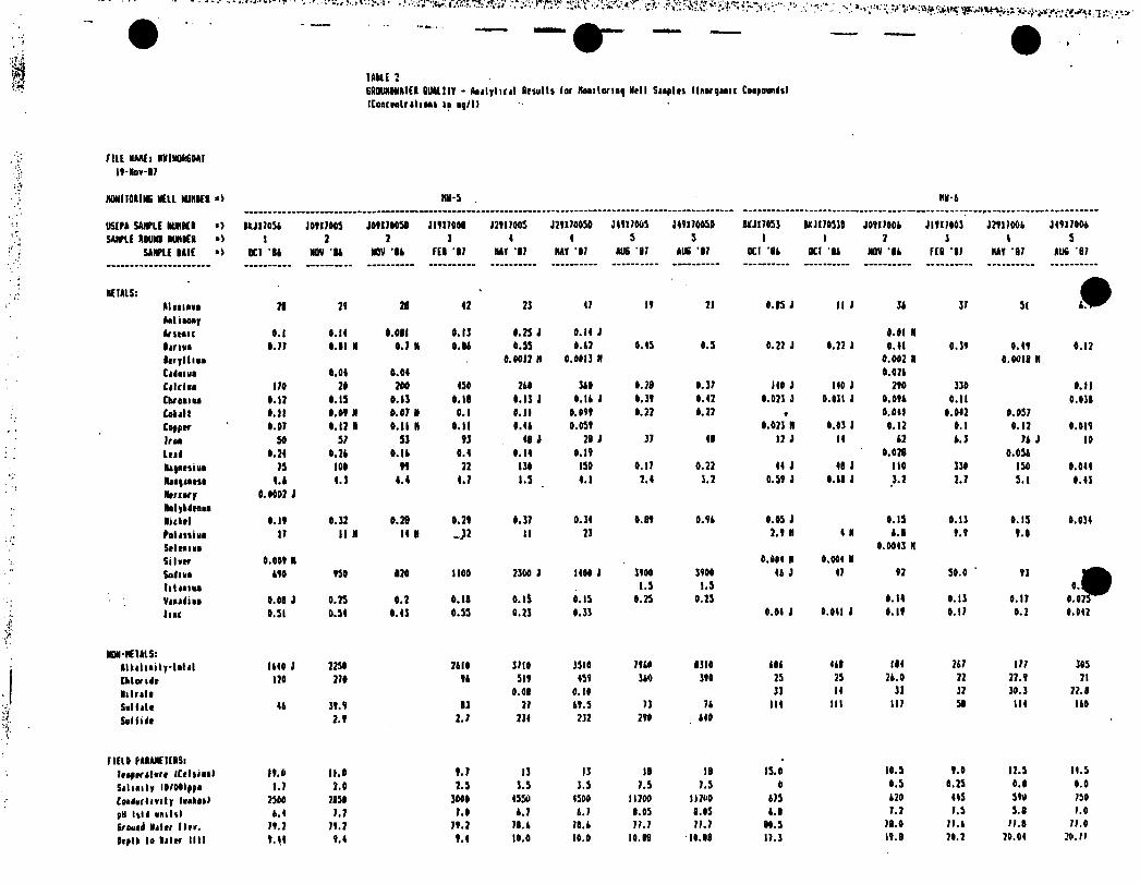
••••», k, ?&rf5V S;irv.'£^*r >?.' :•'. *->~*'&S?$Spt; 'Jtvi V'yJ(>. V.*«
lAbLE 2GROUNDMAIER RUALITY • Analylirjl ftrsul ts lor Honitonny Hell Suplii llnorquic Coapoundf) IConcrnlratioai in nq/11
MU MAHE: HHIHOMOAI ll-Moa-87
MONITORING VEIL HUNGER «> HN-5 HM-4
USIPA SAMPLE HUHBE1 •> ILJI70S4 J01II003 J01I70030 JI1I700R J21I7005 J71I70050 J4117003 J41I7005I WJI7053 WJI70530 J01I7004 JI1I7003 J211I004 J41I7004SAMPLE A DUMB IUHK1 *> 1 2 2 3 4 4 5 5 1 1 7 3 4 5
SAMPLE BAIE O OCT 14 MOV It MOV ’It fEI ’17 HAT ’87 HAT *17 AUS 17 AIK ‘17 OCT 14 OCI ’84 MOV ’84 FEB ’87 HAT ‘87 AUS 87
METALS:4
Alitinna 21 21 28 47 73 47 11 71 0.15 J II J 34 37 51 t™
Anti tonyAntnic «.l 0.14 0.081 0.13 0.23 J 0.14 J 0.01 Hlariao 0.77 0.11 M 0.7 N O.Rt 0.55 0.42 0.45 0.5 0.22 J 0.72 1 0.41 0.31 0.41 0.17Itrylliuo 0.0017 N 0.0013 H 0.002 R 0.0018 HCidama 0.04 0.04 0.074Cnlcioi 170 20 700 450 7t0 340 0.78 0.37 110 i 110 i 210 330 0.11Chroaiu 0.12 0.13 0.11 0.11 0.13 J O.lt J 0.31 0.42 0.073 i 0.031 J 0.014 0.11 0.038Cokalt 0.11 0.01 N 0.07 H 0.1 0.11 0.011 0.27 0.77 * 0.041 0.047 0.037Coyptr 0.07 0.17 R 0.11 H 0.11 0.4t 0.051 0.023 H 0.03 1 0.12 0.1 0.17 0.011Irao so 57 31 13 48 J 71 1 37 48 17 J 14 47 t.3 74 J 10LtiA 0.24 0.7t O.lt 0.4 0.14 0.11 0.028 0.054
Rl|OtliHO 73 100 11 72 130 ISO 0.17 0.22 44 J 48 J 110 330 150 0.044hi|inni 4.A 4. J 4.4 4.7 1.5 4.1 7.4 3.7 0.51 3 0.41 J 3.7 2.7 3.1 0.43
IWrrary 0.0002 JRalykdtoa*Mukrl 0.11 0.12 0.28 0.21 0.37 0.34 0.B1 O.lt 0.05 J 0.13 0.13 0.15 0.034Pol mi ho 17 II H 14 R J* II 23 2.1 H 4 H t.l 1.1 1.0
Srltaiao 0.0043 H
Si law 0.001 H 0.004 R 0.004 R
SodlHO A10 130 120 1100 2300 J 1400 J 3100 3100 44 J 47 17 30.0 ' 13 m
litnniHt 1.3 1.5
Vnandiao 0.08 J 0.23 0.2 0.11 o.ii 0.15 0.23 0.23 0.14 0.13 0.17 0.023
lint 0.31 0.34 0.43 0.55 0.23 0.33 0.04 J 0.041 I 0.11 0.17 0.2 0.042
NON-METALS:Alkiliaity-tolil 1440 J 7750 7410 3710 35I0 7140 8310 484 448 114 747 177 305
Cklondr 170 270 14 511 451 340 310 25 25 24.0 72 27.1 71
Milrilt 0.08 0.10 33 14 33 37 30.3 77.8
Salute 44 31.1 83 27 41.3 73 74 114 III 117 51 114 140
Sol lido 2.1 2.7 734 732 210 440
FIELO PARAMETERS: leapmlart ICflnianl 11.0 11.0 1.7 13 13 18 IB 13.0 10.3 1.0 17.5 11.5
Salinity lO/OOIppo 1.7 7.0 7.5 3.5 3.5 7.5 7.5 0 0.5 0.23 0.0 0.0
Eoadarlmty lantonl 7300 2830 3000 4330 4300 11700 11700 475 470 445 510 750
pH laid aiultl 4.4 7.7 7.0 4.7 4.7 8.03 8.05 4.8 7.2 7.3 3.1 7.0
(round Mjlnr Tina. 71.2 71.7 71.2 78.4 70.4 77.7 77.7 80.5 78.0 77.4 77.0 77.0
Dnplk la liter till 1.44 1.4 1.4 10.0 10.0 10.88 10.88 17.3 11.8 70.7 70.04 70.77

*■.* Vi •>T>'fc 13X-^x.^r t
HUE 1EKWMDMICR tlMltlT - Aailyhcil fteiulti lor Kooitorii
(Caceitritiooi l« *y/ll
rill NAME: NNINDKMI It-Noy-ir
REFINItlOKSiH - CmchImIIm ii keloo quenliiicitiu lint IUSEPA)
or Itii then contract repaired detection Haiti (CLP).J - Coepoaad on puelititively idnliliedi kooevcr, CMpound
tilled to Met ill H critcrti ad ii thcr'ilorr only a
titinted eiloe.
ilk - PiriMter ist uilyitd or reported

IAHE JEADUKOUAIEk SUM 111 - tailyliiil Retails lor Residtolul Noll Soaples lOrqaoic Coopouodt)
ICooreatrolions io up/ll
f HE XAJlf: flUOSSOAI U-Xo*-l7
AESIOCHlIAl ECU NRIIEI ■) M-l M-l M-3hi) Oaotr lodli loadiiea l.loodiito
USEPA sum RIMER •) IXJUOOI JIHIOOI kjiioo? jhiioob IXJUOOI JI1U009
SAME ROUNt RIMER •) 1 ] 1 5 1 SSAME RAIE ■> DC) 'U AUC 17 XI ‘RA RUE 'll DC I ‘BA DUE 'll
VOtAllLC OftEARICS:
tASE/NEUIRAl/ACII
EIIRACIAUE ORSANICSil,I-Oi(hlsrobeaiiatR-Htlhyl-Itaitojoina 17 iActlic Acid, Itlyltilor 17 J2-fetltooot, 4-Hydoiy-l-
Nftkrl IS i
PESIIClDESl
M-l II] U-i UN-1lark Coldbrcl hip Hull
IXJIIOOI 1XJI703I JlfllOlO BXJI7003 IXJII01S IKJWOOA J49II0I2 IXJUOOI JI9I
1 1 3 1 1 1 5 1OCI 14 OCI 'IA AUE ‘II OCI 'IA OCI BA OCI ‘Ik AUE ‘II OCI ‘BA AUI
12 1
KflMEIMSiR - Coactfilrtlioa is baloa quutilicitioo lisil IUSEPA)
or loss Iboo (oolrict raqoirtd detect)so lioits ICLPI.
I - Coopould ms qaelitotiaaly Ideatifiedl koatvtr, coopouad foiled Io owl oil M iriltrii oof is Ibortioro aely u tstioolrd volac.
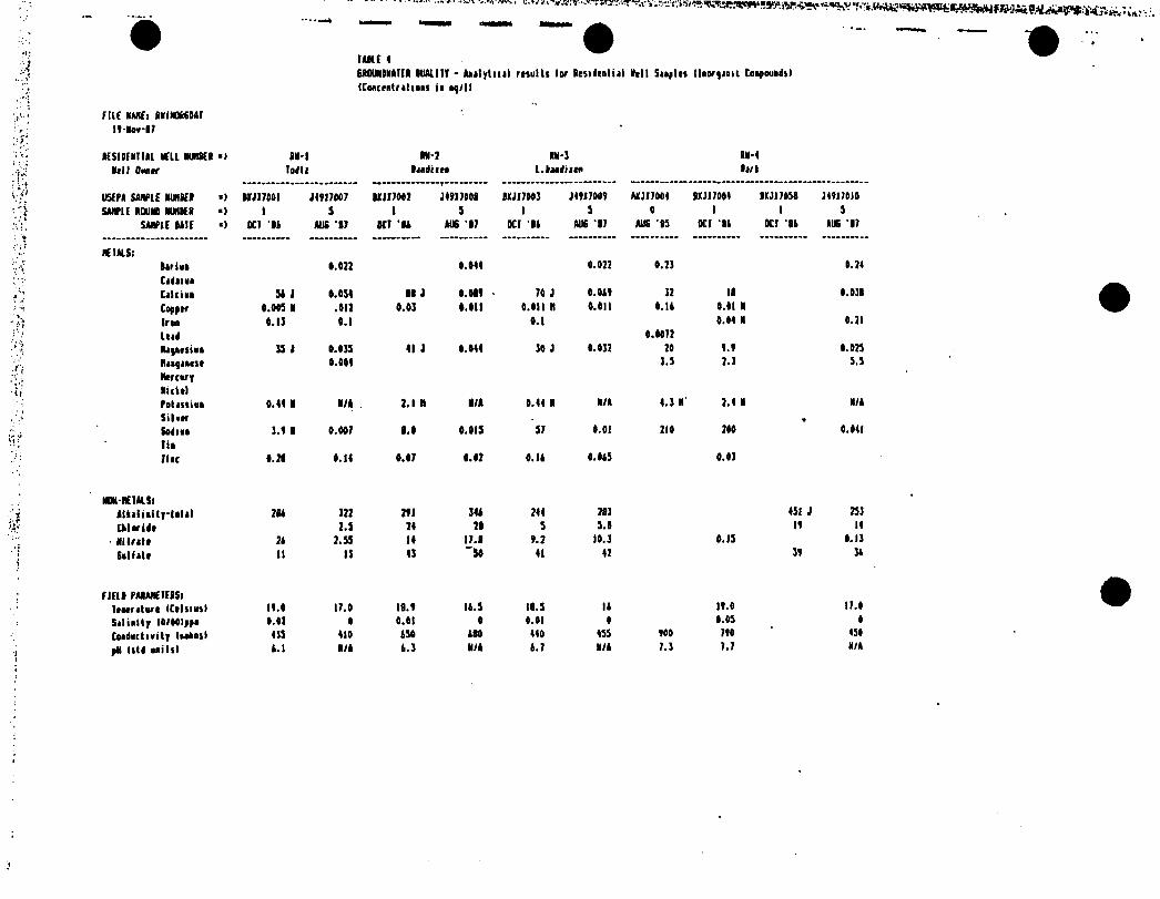
■i
.... .. ... *
I ABU 46A0UMDMAICR OUAIIIT - Aijlyluil results lor Residential Bell Suples llnorpaoit Conpoundsl {Concentrations io np/ll
riu NAHCl ININOft60AI I7-Io*-07
ICSigfBlUl BCIL NUIBH •> IB-1 MI-7 IB-J IB-4
Bell Omer Todli laadiieo l.Baadiiea Bari
’if user* sample buiki ■> BIJ1700I JI7I7007 MJI7007 J4717101 BCJI7003 J4717007 MJI7004 IXJI7004 BKJ1703B J47170I0'A
■ i* SAMPLE ROUND BUHKI •> 1 5 l 5 1 3 0 1 1 3• *: SJMPU UlC ■> SCI u BUS ‘17 OCT u JUS ‘17 OCI 14 AUG ‘17 AUG 13 OCI II OCI 'BA AIS ‘07
ICIAIS:
V V Bari no 0.077 0.044 0.077 0.73 0.74
Cidiioi
CeUioo 34 1 0.034 01 1 0.007 ■ 70 J 0.047 37 IB 0.03B
Copper 0.003 N .017 0.03 0.011 0.011 D 0.011 0.14 0.01 B
Iron 0.11 0.1 0.1 0.04 B 0.71
End 0.0077A '*/ Hi poetIk* 13 J 0.033 41 J 0.044 30 J 0.037 70 7.7 0.073
Riqueit 0.004 3.3 7.3 3.3
MercuryNickel
Potassiua 0.44 1 B/A 7.1 II N/A 0.44 N B/A 4.3 B’ 7.4 H B/A
Silver *Sodno 1.7 B 0.007 1.0 0.013 37 0.01 710 700 0.041
■V: litflic 1.71 0.14 0.07 0.07 0.14 0.043 0.03
NOH-HEIHSi
"•* Alliliiity-tdtil 704 377 771 344 744 783 431 J 733
Cklorldt 7.3 74 70 3 3.8 17 14
■ Bilrel* 74 7.33 14 17.0 7.7 10.3 0.13 0.13■'j Sill ale II 13 43 “30 41 47 37 34
i
flElB PMAHHFISl leacreture (Celsius) 17.0 17.0 18.7 14.3 18.3 14 17.0 17.0
Selikily lO/OOIppi 0.07 0 0.01 0 0.01 0 0.03 0
Conductivity Ittkail 433 410 430 480 440 433 700 770 430
pH (ltd Mill) 4.1 B/A 4.3 N/A 4.7 N/A 7.3 7.7 N/A
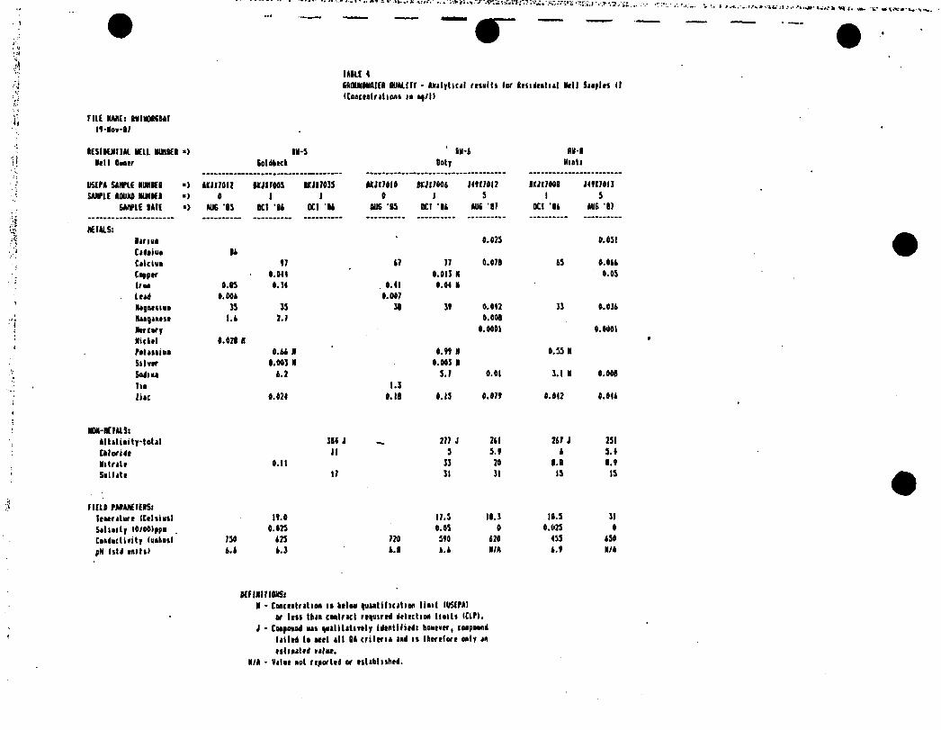
I MU 4SkOtNOMfEI OlMLIff - Alilyticjl multi (or fttsidtatiil Nell Siaplts (I
IConctalrtlions ii ap/l)
rill NMIEi ININOBSBII
lESIBUIItl VEIL UMBER *> ltl-5 ' M-i MI-1
del 1 Baatr SoldtKk Boty Hull
USEPt SMPIE MtlOER *> oiiirou 11717043 IKJI7013 1*717414 Mi I root J44174I7 ItJl7408 74117411
SAHPU 00UN0 MJHNI •> 0 1 1 0 1 3 1 3
SMIPU OAIE •> NI6 'OS OCT ‘It 0C1 It MIS ‘B3 0CI 'It MIS ‘17 0CI ‘It tut 17
HEIMS:
linn 4.473 0.431
Cidoiuo ItCilcin t7 17 77 0.471 ts o.ott
Copptr 0.041 0.411 N 0.43
Iru 0.05 0. H 0.41 4.44 1
itid o.oot 0.047
Magnesian JS 13 18 It 0.442 11 I.Olt
Nisgiaest l.t 2.7 4.000
Ntrcary 0.4001 0.0401
Nictel 0.470 >
Polissiio O.it N 4. tt N 4.33 N
Slim 0.041 N 4.041 1
Sodm t.7 3.7 0.01 3.1 K 0.041
IlO 1.1
iiac 4.424 0.11 4.13 0.07 V 4.047 4.041
NON-REItlSitltilinity-totil 114 J _ 277 J 7tl 717 J 231
Ckloridf II 3 S.t t 3.4
Nitritr 0.11 11 24 l.l l.t
Saillit 17 11 11 13 13
TIEll PMANEIEISlItatnlurt ICtlsiusI lt.0 17.3 II. 1 11.3 11
Sit laity I0/4t)ppo . 4.473 0.43 0 4.023 4
Cnaductirity (aabasl 734 123 720 340 120 433 134
pH Istd anitsl t.t t.l !.l t.t I/A t.t N/t
KE INI f IONS:N - Cucialrition ii MIm quintilicit inn lint IUSEPII
or Icit thin cmImcI rtqtiirrd dilution lints ICIP).
J - Conpoand ns qualitatively idtntilitdi hoitver, conpoand
til ltd t» Mil ill 04 criteria lid is Ihtftlort only in
tslioittd rtlit.N/t - Vilit not reported or tslihlishtd.

. ■ j-‘ j- /'. »>
i
HOLE 5bondiiltr Onilily Analysis PiriioWri
flnorfinic Coipouidil
FMAfCUIS
ijumsamcs
HEIALSi IW-KUIS:
Aliiiui Atkalioity-total
(kitiaoay Cklorido
Arttoic ■Unto
lirloo Sillit(
Itryllua Sill I do
CidoiooCiltliaCkrotiooCokill
toppor
IruUidRifiisiil
lll*|*l(lt
hfCW|
RolykdtiuiNictil
PtlmiuSt I Mi II
Silitr
SediiaTltutoaVtMdlMline
FIELD FMMETERSittacriturt ICtliiuil
Siliiity IO/tO)ppi Coadiclirity lunhosl
pH (ltd Mlitll bauid Oittr Elt*. Btptk to Oitif (It)
HQIEi DotKtioo Units lor lit Uor|»olt Porootlori
rHftd Iroa 0.1 to ISO* o|H*

I AIK 4Ircwilailrr Bull!If kaalym For Motors (titract)bl' Oryiaic Coapoualil
FARklltlEM
IkSE/RtUIRkl/kClt EIlkkClIRE MMHItSt
Fhtaol2-fkttkylyhmol 1-HolkylykMal ],Mlatlk)lfkiaol Icoiyl Alcohol
• Fratubloropbraol 7,4-lichlorofkraol Htlhylbtomoatthaaol 2,5,1,11,ll-fralitii-
HtultCM-14-ol 2,5,1,11,14-FooUbij-
FraliltcM-14-ol 2,2-12-Hflhiiytthoiyi
Elhoiy-EtbMol
2,5,1, 11,11-ProlMiy-
PlllriKMI 2-EUoiy-tl-kolhoiyl-
tlknit5-B*lkyl-l,4-H»uli«aa 1,5,5,7,1-PoolathiotMO
1,2,4-TriUiolano 1,2,4,4-lttratkitpanc l,),3,7-lotrilbiKMr 1,1,3-Trllkiwt l-CyclahtiM-l-ol ,2,4-
liaothylKotato
Naphlkalrat
•kcraapbtbyloat
Initli kcil
FratanolC kill Htiaoolc kcil Oclsoolc kill Itciaoic kcil
totralacaaoic kcid IkiiliiiMlf kcil fhnylprapaiirlioc kcil Switatfroyaaioc kcil
Itainticilic kcil J-lbihylbtaioit kcil 4-Nolkylkoaioic kcil
2- Hctkyl-fMtaooic kcil3- Helkyl fratiaoic kcil 2-Hotkylhciaaoic kcil 2,5-liaatk|rl-lfaira«-
Maaoic kcil Itoioic kcil,l,3-lit (i,i-iiitt»rii(kriM-Nr
NylrOiySOlbOiy-btaiallahylt
2- lhiiioliliattkisat holtiular Sal lacrdrrtkrittt si real
Nwoclkylolkof*
liaolkylbtaiMC1,4-lioolkylktaiooo
i,l,]'lriorlbylhicytls-l2.2.l)htptao-2-ono
4- l2.A.4-triaolkyl-l-tyclohtioii-l-yll-J-
kalca-2-ant«,»-»lil2-Hyiroiyothyll
Mttaoilo
lii-12-tlhlylkciyl)nithilitf
3- Cyclohrimt-l-IMhanol,
Alpha,Alyba-4-HI
kOIEi PtlrtliM liaill lor thr (itractahlo Or|iaic» Paraotlrrt
raaffl Iroa 1.0 to 3501 ag/l.
N-Etkyl-4-Ntlkyl-Itnicnc- Salloaaaila
kutaaoic kcil Hoiathiepaar Hoptanoic kcil licthylphtbalata (alyl looiyl fhtbalalc li-N-Octyl fklkalito li-R-latylphthalaW ItoitaHallaaaailf, M,K,
4-lriotUyl
Rttkant, Isolhiocyanoto 2-Poataoooo, 1-Htlkyl 2-Pootafiooo, 4-Hyloiy-4-
Holhyl•icycla(2.2.1l Hrptao-2-
■oc, 1,2,7-lriMtkyi
M lll'JWSTW T»i«Maaj.

I ARC 1Sroanltoltr DaiJilr Aoalpii Parjirltri (Volatile Organic CMpouiiil
PAAAHCl(AS
VOUIIIE OKMICSi
Cirkon li Ml lilt Action*
2-tuliomtItoitntlolttotIklktlnt CMorllcIttrokylrtlarMCkloroktoiMtCklarttlkott1,1-tlcklorMlktot1- lbUfl -2-Ptnl toont Cklotolor*Iricklvatlbtot Ethyl It*lent Ijrltot* llolill2- Prey Mttklol •icklorolrilltareleltrat Hti*otlA)rl CjrtlalrliiloiMt l-(tkfn-Mm,3- Htthyl-2-ftlonon*
MOtEi ktltcUta litill lor Ik* Volililt Orqioici Pirootltr* r«a|H Iron l.« Ik 23M if PI.
nvr.ir>zr y " vftw * » *• >, a^rroi«ppiy, t*i hV*. Z* IPiV »»«*

I MIC Ifroandaalrr Oaalitf Analysis faraatlrrs IFtilicidttl
FAAAHEIEAS
rtSHCIKS
Alpha-IHCIlll-IHCttlta-IHCSaaaa-MCHtflachlarAlAriaHrplacMir Epni<> Eadatalfaa I litldria A,r-PC£
EadriaEadsailfaa II
1,1-MIEadria AldrkydtEadosallaa Saalfalt
d.d’-KIEadria Ktlaat
NclkoiTtklorCklordaaaloiapktaiArwler-imAracler-1221Ararior-1212•raclar-1212Araclar-1241Arsdor-1231ArKlar-l2M
MIEi Atlttliaa lialti lor tkr Ptilicidt Paraatltriraayrd Irot P.OJ la 2.M ay/l

ATTACHMENT 2
STATEMENT OF SCOPE, CONTINGENCY TRIGGERS AND SCHEDULE
l
SCHEDULE
THE NON-DEFAULT RI/FS SCHEDULE IS AS FOLLOWS:
DuPont shall deliver the Draft RI/FS Report to the EPA on or before July 1, 1988.
DuPont shall deliver the Final RI/FS Report to the EPA on or before August 8, 1988 or within 15 work days after receipt of EPA/s comments on the Draft RI/FS Report. So the delivery of a final RI/FS Report by August 8, 1988 is contingent upon receipt by DuPont of EPA/s comments on the Draft RI/FS Report on or before July 18, 1988.
THE DEFAULT RI/FS SCHEDULE IS AS FOLLOWS:
DuPont shall deliver the Draft FI/FS Report on or before February 15, 1989.
DuPont shall deliver the Final RI/FS Report on or before April 17, 1989 or within .21 work days after receipt of EPA comments on the Draft RI/FS Report. So the delivery of a Final RI/FS Report by April 17,1989 is contingent upon receipt by DuPont of EPA's comments on the Draft RI/FS on or before March 17, 1989.
*
In the event that the default RI/FS Schedule is triggered and DuPont submits a draft RI, FS or RI/FS report prior to the above listed dates, EPA will provide comments on the report within 22 work days of receipt.

ATTACHMENT 2
STATEMENT OP SCOPE AND CONTINGENCY TRIGGERS
1. The RI/FS work program described herein has been developed on the current assumption that the risk associated with the impoundment can be remedied by low level source control (such as encapsulation and/or capping) and some type of ground water monitoring and that further remedial work (such as excavation and treatment of cell wastes) will not be needed.
2. A risk assessment which will test these assumptions will be performed based on pre-RI data and one round of new data, including ground water confirmatory results.
3. The current plan is that the remedial investigation and feasibility study will address both the source area and ground water and that such RI/FS will be completed by August 8, 1988, unless the aforesaid risk assessment indicates that the current assumptions are wrong.
4. If the risk assessment indicates that ground water.monitoring will not be an adequate response and remedial ground water work may be needed, the remedial investigation/feasibility study will be split to address the source area and the ground water as separate operable units. f
5. In the event that the ground water is handled as a subsequent operable unit, such ground water operable unit remedial investigation/feasibility study will be completed by April 17, 1989.
6. In the event that the source area is handled as an operable unit, such source area operable unit remedial investigation/feasibility study will be completed by August 8, 1988. If the risk assessment indicates that more than low-level source control may be required as part of the remedial action, the source area operable unit remedial investigation/feasibility study will be completed by April 17, 1989.