¼ ton through 6 ton capacity
TRANSCRIPT
AIR POWERED
CHAIN HOIST TCR SERIES
¼ Ton through 6 Ton Capacity
Code Number and Serial Number
EFFECTIVE: August 30, 2018
This equipment should not be installed, operated or maintained by any person who has not read and understood all the contents of this manual. Failure to read and comply with the contents of this manual can result in serious bodily injury or death, and/or property damage.
2
Table of Contents
Section Page Number
1.0 Important Information and Warnings………………………………………………………………… 4
1.1 Terms and Summary
1.2 Warning Tags and Labels
2.0 Technical Information………………………………………………………………………………… 8
2.1 Specifications
2.2 Dimensions
2.3 Part Names
3.0 Pre-operational Procedures………………………………………………………………………... 15
3.1 Air Supply System Requirements
3.2 Air Supply Capacity And Regulation
3.3 Lubrication
3.4 Filtration
3.5 Air Dryer
3.6 Piping, Hoses And Fittings
3.7 Mounting Location
3.8 Connecting Hoist to Air Supply
3.9 Mounting the Hoist
3.10 Optional Chain Container
3.11 Non-Stationary Application
3.12 Preoperational Checks and Trial Operation
4.0 Operation……………………………………………………………………………………………. 23
4.1 Introduction
4.2 Shall’s and Shall Not’s for Operation
4.3 Hoist Controls
4.4 Adjusting the Controls
4.5 Operation of the Load Limiter
3
Section Page Number
5.0 Inspection……………………………………………………………………………………………. 28
5.1 General
5.2 Inspection Classification
5.3 Frequent Inspection
5.4 Periodic Inspection
5.5 Occasionally Used Hoists
5.6 Inspection Records
5.7 Inspection Methods and Criteria
6.0 Lubrication…………………………………………………………………………………………... 35
6.1 Air Hoist Lubrication
6.2 Load Chain Lubrication
6.3 Hooks and Suspension Components
7.0 Maintenance & Handling…………………………………………………………………………… 36
7.1 Load Limiter
7.2 Brake
7.3 Load Chain
7.4 Pendant
7.5 Load Sheave Inspection
7.6 Storage
7.7 Outdoor Installation
8.0 Troubleshooting…………………………………………………………………………………….. 44
9.0 Warranty…………………………………………………………………………………………….. 46
10.0 Parts List………………………………………………………………………………………………….. 47
10.1 Main Body
10.2 Cord Control Valve Body
10.3 Pendant Control Valve Body
10.4 Pendant Handle
10.5 Replacement Valve Body
10.6 Optional Chain Container
4
1.0 Important Information and Warnings
1.1 Terms and Summary
This manual provides important information for personnel involved with the installation, operation and maintenance of this product. Although you may be familiar with this or similar equipment, it is strongly recommended that you read this manual before installing, operating or maintaining the product.
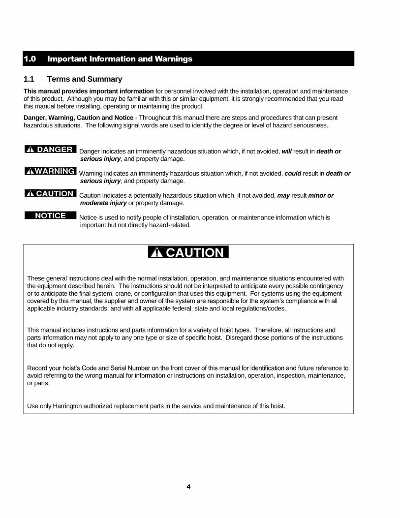
Danger, Warning, Caution and Notice - Throughout this manual there are steps and procedures that can present hazardous situations. The following signal words are used to identify the degree or level of hazard seriousness.
Danger indicates an imminently hazardous situation which, if not avoided, will result in death or serious injury, and property damage.
Warning indicates an imminently hazardous situation which, if not avoided, could result in death or serious injury, and property damage.
Caution indicates a potentially hazardous situation which, if not avoided, may result minor or moderate injury or property damage.
Notice is used to notify people of installation, operation, or maintenance information which is important but not directly hazard-related.
These general instructions deal with the normal installation, operation, and maintenance situations encountered with the equipment described herein. The instructions should not be interpreted to anticipate every possible contingency or to anticipate the final system, crane, or configuration that uses this equipment. For systems using the equipment covered by this manual, the supplier and owner of the system are responsible for the system’s compliance with all applicable industry standards, and with all applicable federal, state and local regulations/codes.
This manual includes instructions and parts information for a variety of hoist types. Therefore, all instructions and parts information may not apply to any one type or size of specific hoist. Disregard those portions of the instructions that do not apply.
Record your hoist’s Code and Serial Number on the front cover of this manual for identification and future reference to avoid referring to the wrong manual for information or instructions on installation, operation, inspection, maintenance, or parts.
Use only Harrington authorized replacement parts in the service and maintenance of this hoist.
5
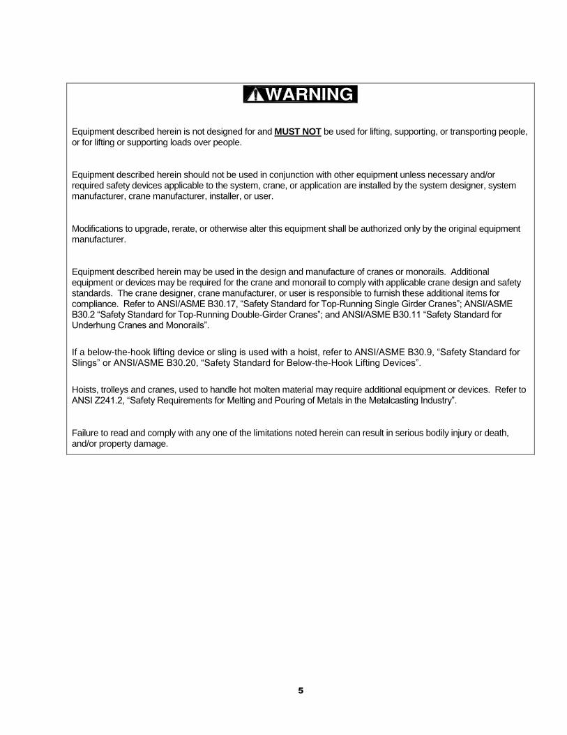
Equipment described herein is not designed for and MUST NOT be used for lifting, supporting, or transporting people, or for lifting or supporting loads over people.
Equipment described herein should not be used in conjunction with other equipment unless necessary and/or required safety devices applicable to the system, crane, or application are installed by the system designer, system manufacturer, crane manufacturer, installer, or user.
Modifications to upgrade, rerate, or otherwise alter this equipment shall be authorized only by the original equipment manufacturer.
Equipment described herein may be used in the design and manufacture of cranes or monorails. Additional equipment or devices may be required for the crane and monorail to comply with applicable crane design and safety standards. The crane designer, crane manufacturer, or user is responsible to furnish these additional items for compliance. Refer to ANSI/ASME B30.17, “Safety Standard for Top-Running Single Girder Cranes”; ANSI/ASME B30.2 “Safety Standard for Top-Running Double-Girder Cranes”; and ANSI/ASME B30.11 “Safety Standard for Underhung Cranes and Monorails”.
If a below-the-hook lifting device or sling is used with a hoist, refer to ANSI/ASME B30.9, “Safety Standard for Slings” or ANSI/ASME B30.20, “Safety Standard for Below-the-Hook Lifting Devices”.
Hoists, trolleys and cranes, used to handle hot molten material may require additional equipment or devices. Refer to ANSI Z241.2, “Safety Requirements for Melting and Pouring of Metals in the Metalcasting Industry”.
Failure to read and comply with any one of the limitations noted herein can result in serious bodily injury or death, and/or property damage.

6
HAZARDOUS AIR PRESSURE IS PRESENT IN THE HOIST, IN THE SUPPLY OF COMPRESSED AIR TO THE HOIST, AND IN THE CONNECTIONS BETWEEN COMPONENTS.
Before performing ANY maintenance on the equipment, de-energize the supply of compressed air to the equipment, and lock and tag the supply device in the de-energized position. Refer to ANSI Z244.1, “Personnel Protection - Lockout/Tagout of Energy Sources.”
Only trained and competent personnel should inspect and repair this equipment.
It is the responsibility of the owner/user to install, inspect, test, maintain, and operate a hoist in accordance with ANSI/ASME B30.16, “Safety Standard for Overhead Hoists”, OSHA Regulations. If the hoist is installed as part of a total lifting system, such as an overhead crane or monorail, it is also the responsibility of the owner/user to comply with the applicable ANSI/ASME B30 volume that addresses that type of equipment.
It is the responsibility of the owner/user to have all personnel that will install, inspect, test, maintain, and operate a hoist read the contents of this manual and applicable portions of ANSI/ASME B30.16, “Safety Standard for Overhead Hoists” and OSHA Regulations. If the hoist is installed as part of a total lifting system, such as an overhead crane, the applicable ANSI/ASME B30 volume that addresses that type of equipment must also be read by all personnel.
If the hoist owner/user requires additional information, or if any information in the manual is not clear, contact Harrington or the distributor of the hoist. Do not install, inspect, test, maintain, or operate this hoist unless this information is fully understood.
A regular schedule of inspection of the hoist in accordance with the requirements of ANSI/ASME B30.16 should be established and records maintained.
7
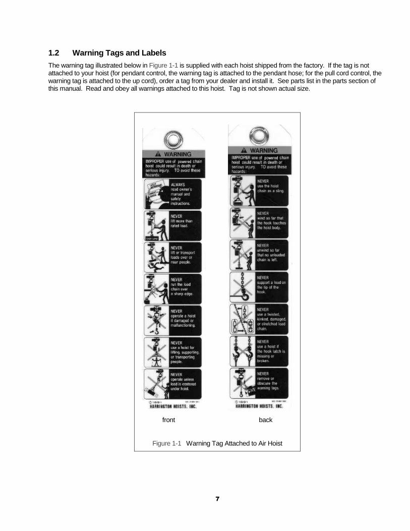
1.2 Warning Tags and Labels
The warning tag illustrated below in Figure 1-1 is supplied with each hoist shipped from the factory. If the tag is not attached to your hoist (for pendant control, the warning tag is attached to the pendant hose; for the pull cord control, the warning tag is attached to the up cord), order a tag from your dealer and install it. See parts list in the parts section of this manual. Read and obey all warnings attached to this hoist. Tag is not shown actual size.
front back
Figure 1-1 Warning Tag Attached to Air Hoist
8
2.0 Technical Information
2.1 Specifications
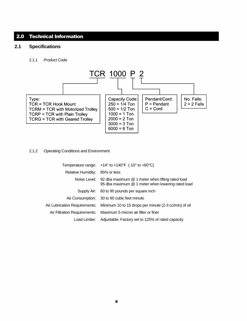
2.1.1 Product Code
2.1.2 Operating Conditions and Environment
Temperature range: +14° to +140°F (-10° to +60°C)
Relative Humidity: 85% or less
Noise Level: 92 dba maximum @ 1 meter when lifting rated load 95 dba maximum @ 1 meter when lowering rated load
Supply Air: 60 to 90 pounds per square inch
Air Consumption: 30 to 90 cubic feet minute
Air Lubrication Requirements: Minimum 10 to 15 drops per minute (2-3 cc/min) of oil
Air Filtration Requirements: Maximum 5 micron air filter or finer
Load Limiter: Adjustable; Factory set to 125% of rated capacity
9
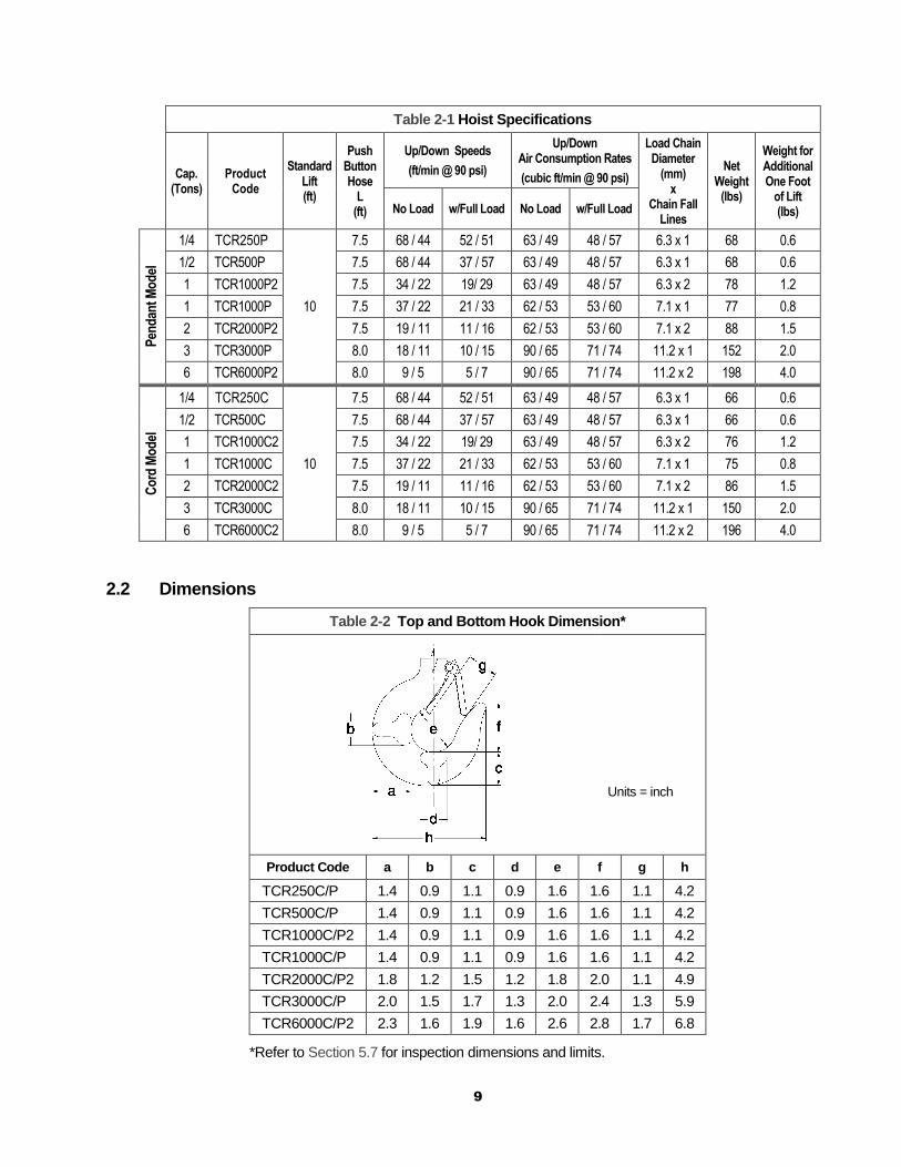
Table 2-1 Hoist Specifications
Cap. (Tons)
Product Code
Standard Lift (ft)
Push Button Hose
L (ft)
Up/Down Speeds
(ft/min @ 90 psi)
Up/Down Air Consumption Rates
(cubic ft/min @ 90 psi)
Load Chain Diameter
(mm) x
Chain Fall Lines
Net Weight
(lbs)
Weight for Additional One Foot
of Lift (lbs) No Load w/Full Load No Load w/Full Load
Pen
dan
t Mo
del
1/4 TCR250P
10
7.5 68 / 44 52 / 51 63 / 49 48 / 57 6.3 x 1 68 0.6
1/2 TCR500P 7.5 68 / 44 37 / 57 63 / 49 48 / 57 6.3 x 1 68 0.6
1 TCR1000P2 7.5 34 / 22 19/ 29 63 / 49 48 / 57 6.3 x 2 78 1.2
1 TCR1000P 7.5 37 / 22 21 / 33 62 / 53 53 / 60 7.1 x 1 77 0.8
2 TCR2000P2 7.5 19 / 11 11 / 16 62 / 53 53 / 60 7.1 x 2 88 1.5
3 TCR3000P 8.0 18 / 11 10 / 15 90 / 65 71 / 74 11.2 x 1 152 2.0
6 TCR6000P2 8.0 9 / 5 5 / 7 90 / 65 71 / 74 11.2 x 2 198 4.0
Co
rd M
od
el
1/4 TCR250C
10
7.5 68 / 44 52 / 51 63 / 49 48 / 57 6.3 x 1 66 0.6
1/2 TCR500C 7.5 68 / 44 37 / 57 63 / 49 48 / 57 6.3 x 1 66 0.6
1 TCR1000C2 7.5 34 / 22 19/ 29 63 / 49 48 / 57 6.3 x 2 76 1.2
1 TCR1000C 7.5 37 / 22 21 / 33 62 / 53 53 / 60 7.1 x 1 75 0.8
2 TCR2000C2 7.5 19 / 11 11 / 16 62 / 53 53 / 60 7.1 x 2 86 1.5
3 TCR3000C 8.0 18 / 11 10 / 15 90 / 65 71 / 74 11.2 x 1 150 2.0
6 TCR6000C2 8.0 9 / 5 5 / 7 90 / 65 71 / 74 11.2 x 2 196 4.0
2.2 Dimensions
Table 2-2 Top and Bottom Hook Dimension*
Units = inch
Product Code a b c d e f g h
TCR250C/P 1.4 0.9 1.1 0.9 1.6 1.6 1.1 4.2
TCR500C/P 1.4 0.9 1.1 0.9 1.6 1.6 1.1 4.2
TCR1000C/P2 1.4 0.9 1.1 0.9 1.6 1.6 1.1 4.2
TCR1000C/P 1.4 0.9 1.1 0.9 1.6 1.6 1.1 4.2
TCR2000C/P2 1.8 1.2 1.5 1.2 1.8 2.0 1.1 4.9
TCR3000C/P 2.0 1.5 1.7 1.3 2.0 2.4 1.3 5.9
TCR6000C/P2 2.3 1.6 1.9 1.6 2.6 2.8 1.7 6.8
*Refer to Section 5.7 for inspection dimensions and limits.
10
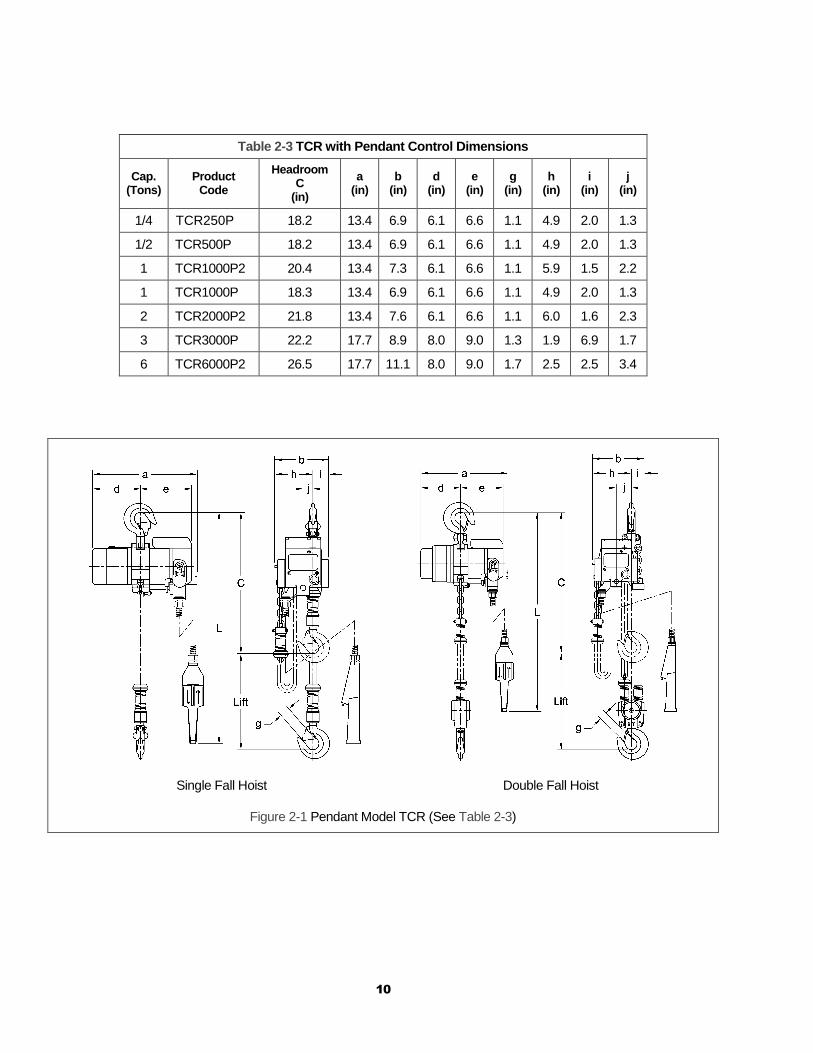
Table 2-3 TCR with Pendant Control Dimensions
Cap. (Tons)
Product Code
Headroom C
(in)
a (in)
b (in)
d (in)
e (in)
g (in)
h (in)
i (in)
j (in)
1/4 TCR250P 18.2 13.4 6.9 6.1 6.6 1.1 4.9 2.0 1.3
1/2 TCR500P 18.2 13.4 6.9 6.1 6.6 1.1 4.9 2.0 1.3
1 TCR1000P2 20.4 13.4 7.3 6.1 6.6 1.1 5.9 1.5 2.2
1 TCR1000P 18.3 13.4 6.9 6.1 6.6 1.1 4.9 2.0 1.3
2 TCR2000P2 21.8 13.4 7.6 6.1 6.6 1.1 6.0 1.6 2.3
3 TCR3000P 22.2 17.7 8.9 8.0 9.0 1.3 1.9 6.9 1.7
6 TCR6000P2 26.5 17.7 11.1 8.0 9.0 1.7 2.5 2.5 3.4
Single Fall Hoist Double Fall Hoist
Figure 2-1 Pendant Model TCR (See Table 2-3)
11
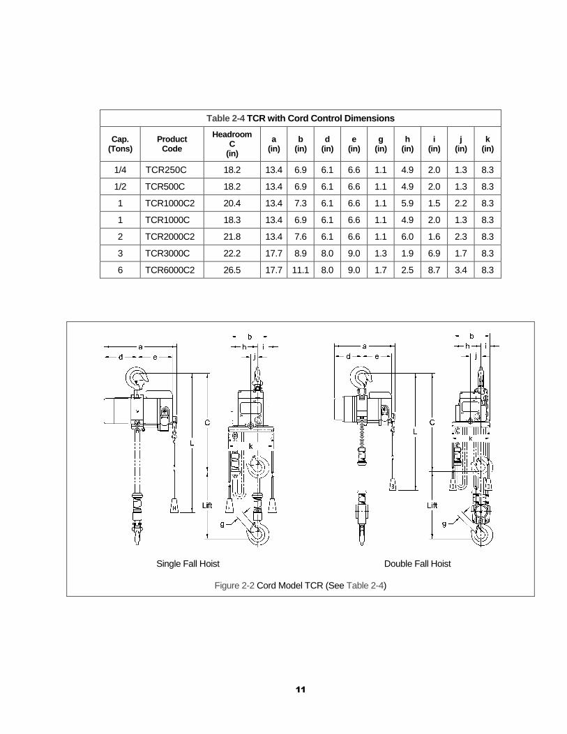
Table 2-4 TCR with Cord Control Dimensions
Cap. (Tons)
Product Code
Headroom C
(in)
a (in)
b (in)
d (in)
e (in)
g (in)
h (in)
i (in)
j (in)
k (in)
1/4 TCR250C 18.2 13.4 6.9 6.1 6.6 1.1 4.9 2.0 1.3 8.3
1/2 TCR500C 18.2 13.4 6.9 6.1 6.6 1.1 4.9 2.0 1.3 8.3
1 TCR1000C2 20.4 13.4 7.3 6.1 6.6 1.1 5.9 1.5 2.2 8.3
1 TCR1000C 18.3 13.4 6.9 6.1 6.6 1.1 4.9 2.0 1.3 8.3
2 TCR2000C2 21.8 13.4 7.6 6.1 6.6 1.1 6.0 1.6 2.3 8.3
3 TCR3000C 22.2 17.7 8.9 8.0 9.0 1.3 1.9 6.9 1.7 8.3
6 TCR6000C2 26.5 17.7 11.1 8.0 9.0 1.7 2.5 8.7 3.4 8.3
Single Fall Hoist Double Fall Hoist
Figure 2-2 Cord Model TCR (See Table 2-4)

12
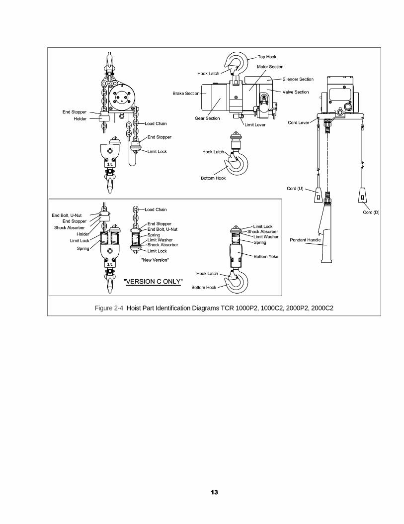
2.3 Part Names
Figure 2-3 Hoist Part Identification Diagrams TCR 250P, 250C, 500P, 500C, 1000P, 1000C
13
Figure 2-4 Hoist Part Identification Diagrams TCR 1000P2, 1000C2, 2000P2, 2000C2
14
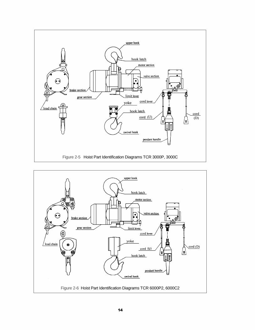
Figure 2-5 Hoist Part Identification Diagrams TCR 3000P, 3000C
Figure 2-6 Hoist Part Identification Diagrams TCR 6000P2, 6000C2
15
3.0 Preoperational Procedures
3.1 Air Supply System Requirements
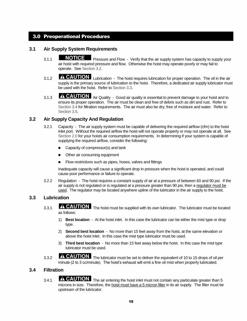
3.1.1 Pressure and Flow - Verify that the air supply system has capacity to supply your air hoist with required pressure and flow. Otherwise the hoist may operate poorly or may fail to operate. See Section 3.2.
3.1.2 Lubrication - The hoist requires lubrication for proper operation. The oil in the air supply is the primary source of lubrication to the hoist. Therefore, a dedicated air supply lubricator must be used with the hoist. Refer to Section 3.3.
3.1.3 Air Quality - Good air quality is essential to prevent damage to your hoist and to ensure its proper operation. The air must be clean and free of debris such as dirt and rust. Refer to Section 3.4 for filtration requirements. The air must also be dry; free of moisture and water. Refer to Section 3.5.
3.2 Air Supply Capacity And Regulation
3.2.1 Capacity - The air supply system must be capable of delivering the required airflow (cfm) to the hoist inlet port. Without the required airflow the hoist will not operate properly or may not operate at all. See Section 2.0 for your hoists air consumption requirements. In determining if your system is capable of supplying the required airflow, consider the following:
Capacity of compressor(s) and tank
Other air consuming equipment
Flow restrictions such as pipes, hoses, valves and fittings
Inadequate capacity will cause a significant drop in pressure when the hoist is operated, and could cause poor performance or failure to operate.
3.2.2 Regulation - The hoist requires a constant supply of air at a pressure of between 60 and 90 psi. If the air supply is not regulated or is regulated at a pressure greater than 90 psi, then a regulator must be used. The regulator may be located anywhere upline of the lubricator in the air supply to the hoist.
3.3 Lubrication
3.3.1 The hoist must be supplied with its own lubricator. The lubricator must be located as follows:
1) Best location - At the hoist inlet. In this case the lubricator can be either the mist type or drop type.
2) Second best location - No more than 15 feet away from the hoist, at the same elevation or above the hoist inlet. In this case the mist type lubricator must be used.
3) Third best location - No more than 15 feet away below the hoist. In this case the mist type lubricator must be used.
3.3.2 The lubricator must be set to deliver the equivalent of 10 to 15 drops of oil per minute (2 to 3 cc/minute). The hoist’s exhaust will emit a fine oil mist when properly lubricated.
3.4 Filtration
3.4.1 The air entering the hoist inlet must not contain any particulate greater than 5 microns in size. Therefore, the hoist must have a 5 micron filter in its air supply. The filter must be upstream of the lubricator.

16
3.4.2 The filter servicing the hoist can also service other hoists and air consuming equipment. In this case, the air filter must be in sized for the total air consumption of the equipment it is servicing.
3.5 Air Dryer - To prevent corrosion and hoist malfunction, employ an air dryer in the air
supply system to ensure that dry air is supplied to the hoist. If there is moisture in the air supplied to the hoist, this moisture will cause corrosion on internal hoist components during periods when the hoist is idle leading to hoist malfunction.
3.6 Piping, Hoses And Fittings
3.6.1 System Configuration - The system should be configured as shown in Figure 3-1. Since moisture tends to accumulate in compressed air systems, corrosion may result if the system is not periodically drained.
Arrange for a drain in the air supply piping at the lowest point in the piping, and
Periodically drain the system to remove moisture/water from the system and to prevent corrosion.
Filter, regulator (if equipped), and lubricator must be arranged in the order shown in Figure 3-2.
Figure 3-1 Diagram of Air Supply Configuration (Typical)
Figure 3-2 Typical Air Supply Filter, Regulator and Lubricator.
17
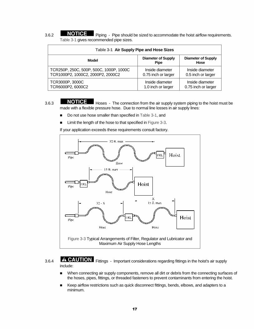
3.6.2 Piping - Pipe should be sized to accommodate the hoist airflow requirements. Table 3-1 gives recommended pipe sizes.
Table 3-1 Air Supply Pipe and Hose Sizes
Model Diameter of Supply
Pipe Diameter of Supply
Hose
TCR250P, 250C, 500P, 500C, 1000P, 1000C TCR1000P2, 1000C2, 2000P2, 2000C2
Inside diameter 0.75 inch or larger
Inside diameter 0.5 inch or larger
TCR3000P, 3000C TCR6000P2, 6000C2
Inside diameter 1.0 inch or larger
Inside diameter 0.75 inch or larger
3.6.3 Hoses - The connection from the air supply system piping to the hoist must be made with a flexible pressure hose. Due to normal line losses in air supply lines:
Do not use hose smaller than specified in Table 3-1, and
Limit the length of the hose to that specified in Figure 3-3.
If your application exceeds these requirements consult factory.
Figure 3-3 Typical Arrangements of Filter, Regulator and Lubricator and Maximum Air Supply Hose Lengths
3.6.4 Fittings - Important considerations regarding fittings in the hoist's air supply include:
When connecting air supply components, remove all dirt or debris from the connecting surfaces of the hoses, pipes, fittings, or threaded fasteners to prevent contaminants from entering the hoist.
Keep airflow restrictions such as quick disconnect fittings, bends, elbows, and adapters to a minimum.
18
3.6.5 Before connecting the hoist to its air supply line; perform the proper draining and purging procedures to prevent contaminants or moisture from entering the hoist.
3.7 Mounting Location
3.7.1 Prior to mounting the hoist ensure that the suspension and it supporting structure are adequate to support the hoist and its loads. If necessary consult a professional that is qualified to evaluate the adequacy of the suspension location and its supporting structure.
3.7.2 See Section 7.6 for outdoor installation considerations.
3.8 Connecting Hoist to Air Supply
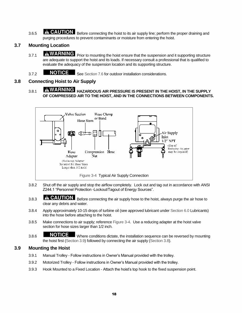
3.8.1 HAZARDOUS AIR PRESSURE IS PRESENT IN THE HOIST, IN THE SUPPLY OF COMPRESSED AIR TO THE HOIST, AND IN THE CONNECTIONS BETWEEN COMPONENTS.
Figure 3-4 Typical Air Supply Connection
3.8.2 Shut off the air supply and stop the airflow completely. Lock out and tag out in accordance with ANSI Z244.1 “Personnel Protection -Lockout/Tagout of Energy Sources”.
3.8.3 Before connecting the air supply hose to the hoist, always purge the air hose to clear any debris and water.
3.8.4 Apply approximately 10-15 drops of turbine oil (see approved lubricant under Section 6.0 Lubricants) into the hose before attaching to the hoist.
3.8.5 Make connections to air supply; reference Figure 3-4. Use a reducing adapter at the hoist valve section for hose sizes larger than 1/2 inch.
3.8.6 Where conditions dictate, the installation sequence can be reversed by mounting the hoist first (Section 3.9) followed by connecting the air supply (Section 3.8).
3.9 Mounting the Hoist
3.9.1 Manual Trolley - Follow instructions in Owner’s Manual provided with the trolley.
3.9.2 Motorized Trolley - Follow instructions in Owner’s Manual provided with the trolley.
3.9.3 Hook Mounted to a Fixed Location - Attach the hoist’s top hook to the fixed suspension point.
19
3.9.4 Ensure that the fixed suspension point rests on the center of the hook’s saddle and that the hook’s latch is engaged .
3.10 Optional Chain Container
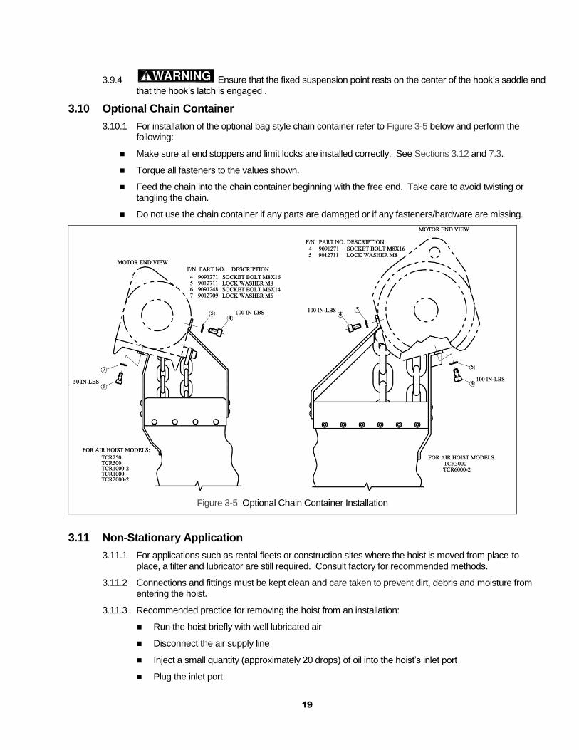
3.10.1 For installation of the optional bag style chain container refer to Figure 3-5 below and perform the following:
Make sure all end stoppers and limit locks are installed correctly. See Sections 3.12 and 7.3.
Torque all fasteners to the values shown.
Feed the chain into the chain container beginning with the free end. Take care to avoid twisting or tangling the chain.
Do not use the chain container if any parts are damaged or if any fasteners/hardware are missing.
Figure 3-5 Optional Chain Container Installation
3.11 Non-Stationary Application
3.11.1 For applications such as rental fleets or construction sites where the hoist is moved from place-to-place, a filter and lubricator are still required. Consult factory for recommended methods.
3.11.2 Connections and fittings must be kept clean and care taken to prevent dirt, debris and moisture from entering the hoist.
3.11.3 Recommended practice for removing the hoist from an installation:
Run the hoist briefly with well lubricated air
Disconnect the air supply line
Inject a small quantity (approximately 20 drops) of oil into the hoist’s inlet port
Plug the inlet port
20
3.12 Preoperational Checks and Trial Operation
3.12.1 Check for the availability of required operating air pressure of between 60 PSI to 90 PSI at the hoist's inlet port before trying to operate the hoist.
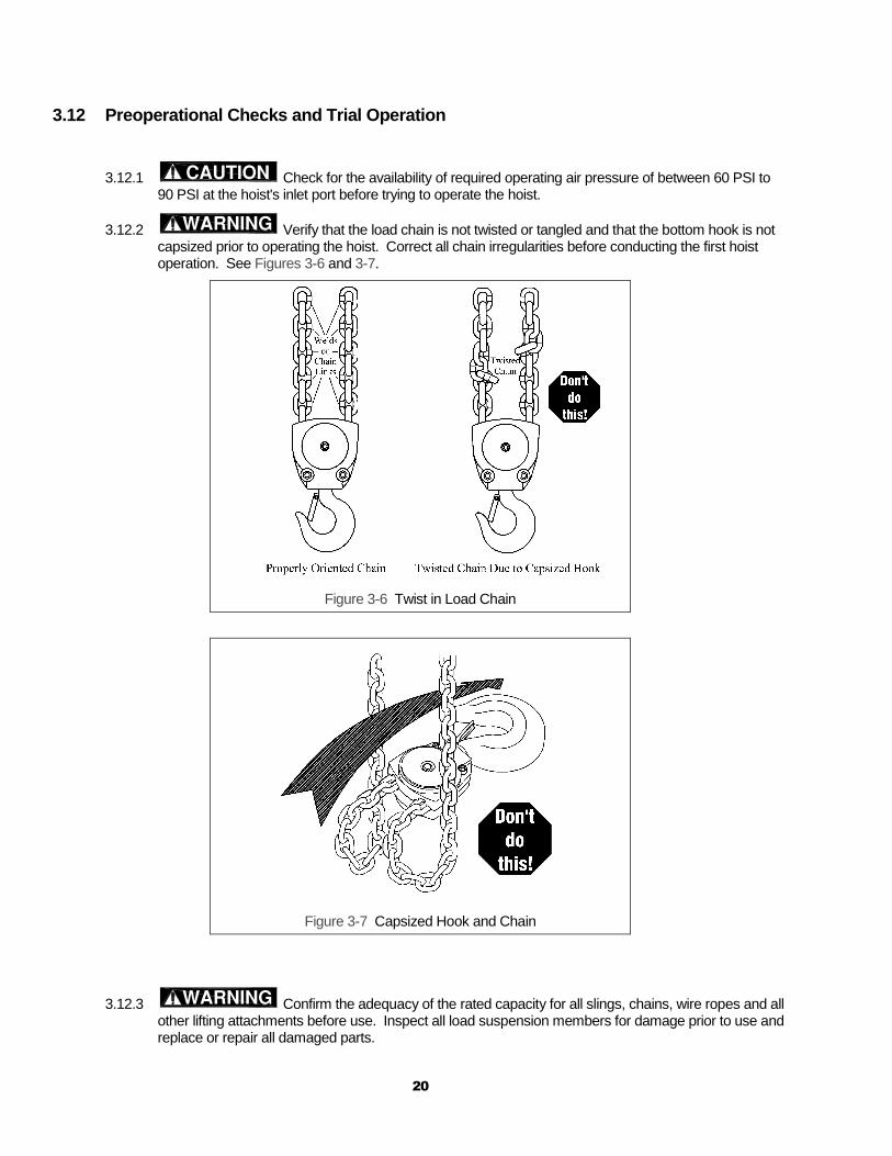
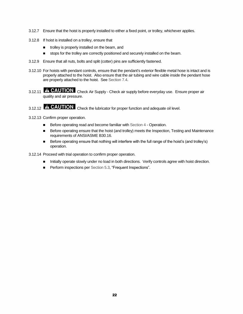
3.12.2 Verify that the load chain is not twisted or tangled and that the bottom hook is not capsized prior to operating the hoist. Correct all chain irregularities before conducting the first hoist operation. See Figures 3-6 and 3-7.
Figure 3-6 Twist in Load Chain
Figure 3-7 Capsized Hook and Chain
3.12.3 Confirm the adequacy of the rated capacity for all slings, chains, wire ropes and all other lifting attachments before use. Inspect all load suspension members for damage prior to use and replace or repair all damaged parts.

21
3.12.4 For Models TCR-250P&C, 500P&C, 1000P2&C2, 1000P&C and 2000P2&C2 verify the limit locks are properly installed on the load chain. For reference see Figure 3-8 for hoist versions 1, A, B and C and Section 7.3.2. For Models TCR-3000P&C and 6000P2&C2 verify that the chain/limit lever is operational and can move freely in both the up and down directions. For reference see Figure 3-9.
Versions 1, A and B Version C Only
Figure 3-8 Limit Switch Components
Figure 3-9 Limit Switch Components
3.12.5 Measure and record the “K” dimension of all hooks on hoist. See Table 5-6 under Section 5, “Inspection”. Always use the same side of the hook to measure and record the "K" dimension.
3.12.6 Record the hoist Code Number and Serial Number (from the nameplate on the hoist – see Section 10) in the space provided on the cover of this manual.
22
3.12.7 Ensure that the hoist is properly installed to either a fixed point, or trolley, whichever applies.
3.12.8 If hoist is installed on a trolley, ensure that
trolley is properly installed on the beam, and
stops for the trolley are correctly positioned and securely installed on the beam.
3.12.9 Ensure that all nuts, bolts and split (cotter) pins are sufficiently fastened.
3.12.10 For hoists with pendant controls, ensure that the pendant's exterior flexible metal hose is intact and is properly attached to the hoist. Also ensure that the air tubing and wire cable inside the pendant hose are properly attached to the hoist. See Section 7.4.
3.12.11 Check Air Supply - Check air supply before everyday use. Ensure proper air quality and air pressure.
3.12.12 Check the lubricator for proper function and adequate oil level.
3.12.13 Confirm proper operation.
Before operating read and become familiar with Section 4 - Operation.
Before operating ensure that the hoist (and trolley) meets the Inspection, Testing and Maintenance
requirements of ANSI/ASME B30.16.
Before operating ensure that nothing will interfere with the full range of the hoist’s (and trolley’s)
operation.
3.12.14 Proceed with trial operation to confirm proper operation.
Initially operate slowly under no load in both directions. Verify controls agree with hoist direction.
Perform inspections per Section 5.3, “Frequent Inspections”.
23
4.0 Operation
4.1 Introduction
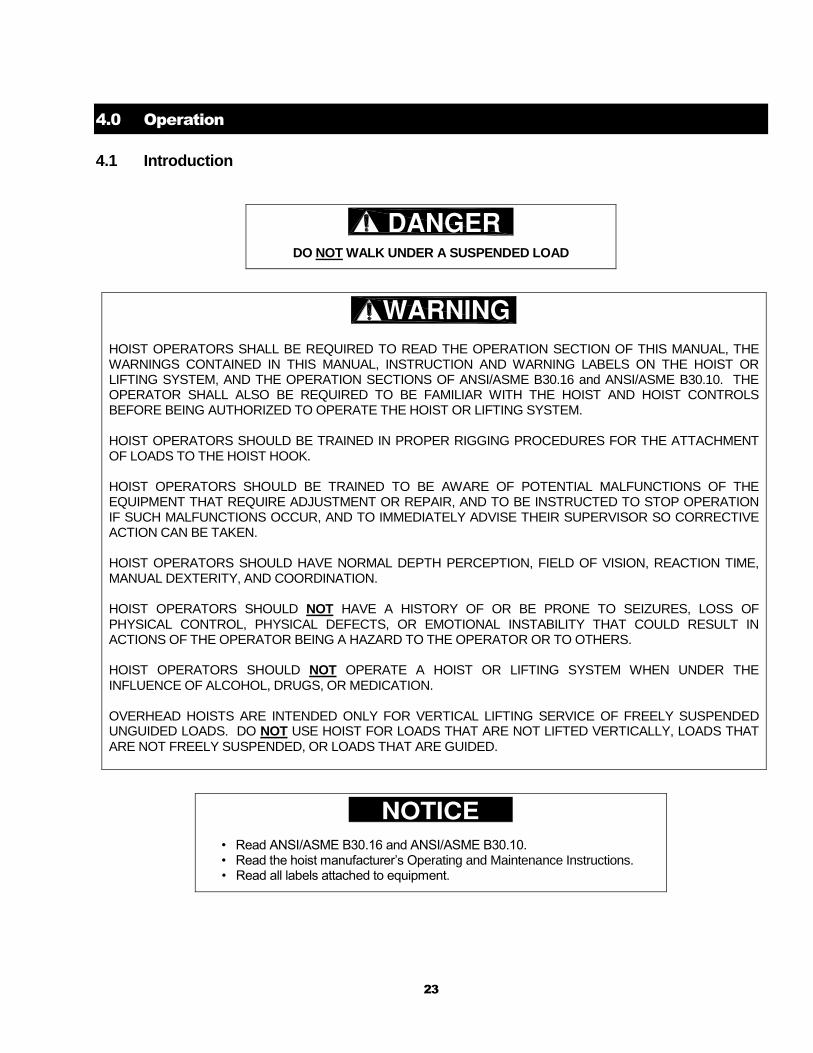
DO NOT WALK UNDER A SUSPENDED LOAD
HOIST OPERATORS SHALL BE REQUIRED TO READ THE OPERATION SECTION OF THIS MANUAL, THE WARNINGS CONTAINED IN THIS MANUAL, INSTRUCTION AND WARNING LABELS ON THE HOIST OR LIFTING SYSTEM, AND THE OPERATION SECTIONS OF ANSI/ASME B30.16 and ANSI/ASME B30.10. THE OPERATOR SHALL ALSO BE REQUIRED TO BE FAMILIAR WITH THE HOIST AND HOIST CONTROLS BEFORE BEING AUTHORIZED TO OPERATE THE HOIST OR LIFTING SYSTEM. HOIST OPERATORS SHOULD BE TRAINED IN PROPER RIGGING PROCEDURES FOR THE ATTACHMENT OF LOADS TO THE HOIST HOOK. HOIST OPERATORS SHOULD BE TRAINED TO BE AWARE OF POTENTIAL MALFUNCTIONS OF THE EQUIPMENT THAT REQUIRE ADJUSTMENT OR REPAIR, AND TO BE INSTRUCTED TO STOP OPERATION IF SUCH MALFUNCTIONS OCCUR, AND TO IMMEDIATELY ADVISE THEIR SUPERVISOR SO CORRECTIVE ACTION CAN BE TAKEN. HOIST OPERATORS SHOULD HAVE NORMAL DEPTH PERCEPTION, FIELD OF VISION, REACTION TIME, MANUAL DEXTERITY, AND COORDINATION. HOIST OPERATORS SHOULD NOT HAVE A HISTORY OF OR BE PRONE TO SEIZURES, LOSS OF PHYSICAL CONTROL, PHYSICAL DEFECTS, OR EMOTIONAL INSTABILITY THAT COULD RESULT IN ACTIONS OF THE OPERATOR BEING A HAZARD TO THE OPERATOR OR TO OTHERS. HOIST OPERATORS SHOULD NOT OPERATE A HOIST OR LIFTING SYSTEM WHEN UNDER THE INFLUENCE OF ALCOHOL, DRUGS, OR MEDICATION. OVERHEAD HOISTS ARE INTENDED ONLY FOR VERTICAL LIFTING SERVICE OF FREELY SUSPENDED UNGUIDED LOADS. DO NOT USE HOIST FOR LOADS THAT ARE NOT LIFTED VERTICALLY, LOADS THAT ARE NOT FREELY SUSPENDED, OR LOADS THAT ARE GUIDED.
• Read ANSI/ASME B30.16 and ANSI/ASME B30.10. • Read the hoist manufacturer’s Operating and Maintenance Instructions. • Read all labels attached to equipment.
24
The operation of an overhead hoist involves more than activating the hoist’s controls. Per the ANSI/ASME B30 standards, the use of an overhead hoist is subject to certain hazards that cannot be mitigated by engineered features, but only by the exercise of intelligence, care, common sense, and experience in anticipating the effects and results of activating the hoist’s controls. Use this guidance in conjunction with other warnings, cautions, and notices in this manual to govern the operation and use of your overhead hoist.
4.2 Shall’s and Shall Not’s for Operation
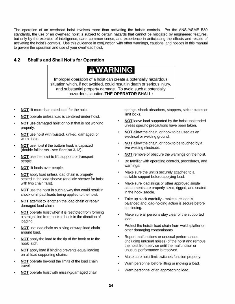
Improper operation of a hoist can create a potentially hazardous situation which, if not avoided, could result in death or serious injury,
and substantial property damage. To avoid such a potentially hazardous situation THE OPERATOR SHALL:
• NOT lift more than rated load for the hoist.
• NOT operate unless load is centered under hoist.
• NOT use damaged hoist or hoist that is not working properly.
• NOT use hoist with twisted, kinked, damaged, or worn chain.
• NOT use hoist if the bottom hook is capsized (double fall hoists - see Section 3.12).
• NOT use the hoist to lift, support, or transport people.
• NOT lift loads over people.
• NOT apply load unless load chain is properly seated in the load sheave (and idle sheave for hoist with two chain falls).
• NOT use the hoist in such a way that could result in shock or impact loads being applied to the hoist.
• NOT attempt to lengthen the load chain or repair damaged load chain.
• NOT operate hoist when it is restricted from forming a straight line from hook to hook in the direction of loading.
• NOT use load chain as a sling or wrap load chain around load.
• NOT apply the load to the tip of the hook or to the hook latch.
• NOT apply load if binding prevents equal loading on all load supporting chains.
• NOT operate beyond the limits of the load chain travel.
• NOT operate hoist with missing/damaged chain
springs, shock absorbers, stoppers, striker plates or limit locks.
• NOT leave load supported by the hoist unattended unless specific precautions have been taken.
• NOT allow the chain, or hook to be used as an electrical or welding ground.
• NOT allow the chain, or hook to be touched by a live welding electrode.
• NOT remove or obscure the warnings on the hoist.
• Be familiar with operating controls, procedures, and warnings.
• Make sure the unit is securely attached to a suitable support before applying load.
• Make sure load slings or other approved single attachments are properly sized, rigged, and seated in the hook saddle.
• Take up slack carefully - make sure load is balanced and load-holding action is secure before continuing.
• Make sure all persons stay clear of the supported load.
• Protect the hoist’s load chain from weld splatter or other damaging contaminants.
• Report malfunctions or unusual performances (including unusual noises) of the hoist and remove the hoist from service until the malfunction or unusual performance is resolved.
• Make sure hoist limit switches function properly.
• Warn personnel before lifting or moving a load.
• Warn personnel of an approaching load.

25
Improper operation of a hoist can create a potentially hazardous situation which, if not avoided, could result in minor or moderate
injury, or property damage. To avoid such a potentially hazardous situation THE OPERATOR SHALL:
• Maintain a firm footing or be otherwise secured when operating the hoist.
• Check brake function by tensioning the hoist prior to each lift operation.
• Use hook latches. Latches are to retain slings, chains, etc. under slack conditions only.
• Make sure the hook latches are closed and not supporting any parts of the load.
• Make sure the load is free to move and will clear all obstructions.
• Avoid swinging the load or hook.
• Make sure hook travel is in the same direction as shown on controls.
• Inspect the hoist regularly, replace damaged or worn parts, and keep appropriate records of maintenance.
• Use the hoist manufacturer’s recommended parts when repairing the unit.
• Lubricate load chain per hoist manufacturer’s recommendations.
• NOT use the hoist load limiting or warning device to measure load.
• NOT use limit switches as routine operating stops. They are emergency devices only.
• NOT allow your attention to be diverted from operating the hoist.
• NOT allow the hoist to be subjected to sharp contact with other hoists, structures, or objects through misuse.
• NOT adjust or repair the hoist unless qualified to perform such adjustments or repairs.
4.3 Hoist Controls
4.3.1 For hoists mounted to motorized trolleys follow the control instruction included in the trolley ‘s Owner’s Manual.
4.3.2 Pendant Control - When using the pendant control depress the up lever to raise the hoist or the down lever to lower the hoist as shown in Figure 4-1 below. To stop motion release the lever switches.
Figure 4-1 Pendant Control
26
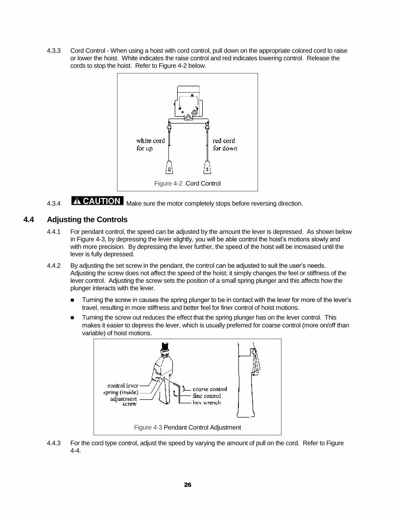
4.3.3 Cord Control - When using a hoist with cord control, pull down on the appropriate colored cord to raise or lower the hoist. White indicates the raise control and red indicates lowering control. Release the cords to stop the hoist. Refer to Figure 4-2 below.
Figure 4-2 Cord Control
4.3.4 Make sure the motor completely stops before reversing direction.
4.4 Adjusting the Controls
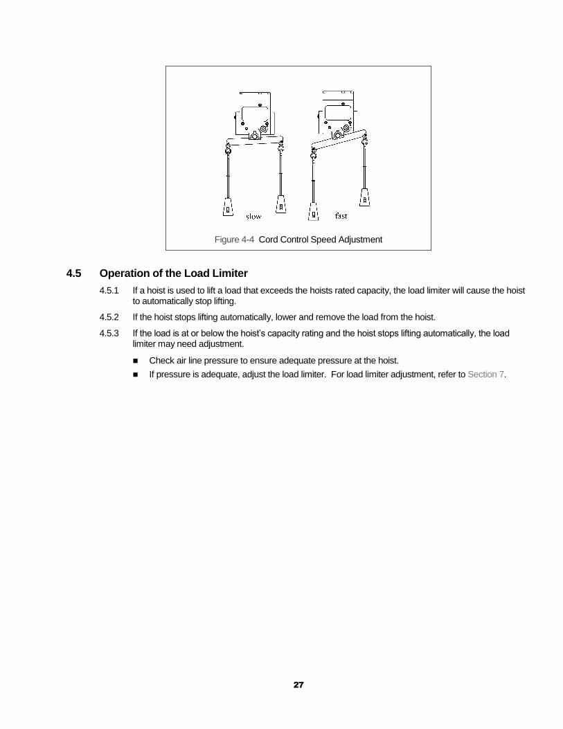
4.4.1 For pendant control, the speed can be adjusted by the amount the lever is depressed. As shown below in Figure 4-3, by depressing the lever slightly, you will be able control the hoist’s motions slowly and with more precision. By depressing the lever further, the speed of the hoist will be increased until the lever is fully depressed.
4.4.2 By adjusting the set screw in the pendant, the control can be adjusted to suit the user’s needs. Adjusting the screw does not affect the speed of the hoist; it simply changes the feel or stiffness of the lever control. Adjusting the screw sets the position of a small spring plunger and this affects how the plunger interacts with the lever.
Turning the screw in causes the spring plunger to be in contact with the lever for more of the lever’s
travel, resulting in more stiffness and better feel for finer control of hoist motions.
Turning the screw out reduces the effect that the spring plunger has on the lever control. This
makes it easier to depress the lever, which is usually preferred for coarse control (more on/off than
variable) of hoist motions.
Figure 4-3 Pendant Control Adjustment
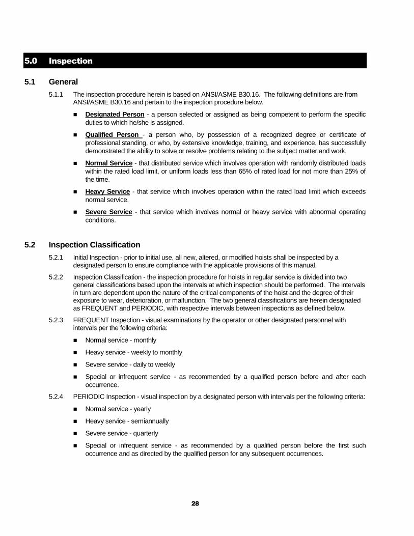
4.4.3 For the cord type control, adjust the speed by varying the amount of pull on the cord. Refer to Figure 4-4.
27
Figure 4-4 Cord Control Speed Adjustment
4.5 Operation of the Load Limiter
4.5.1 If a hoist is used to lift a load that exceeds the hoists rated capacity, the load limiter will cause the hoist to automatically stop lifting.
4.5.2 If the hoist stops lifting automatically, lower and remove the load from the hoist.
4.5.3 If the load is at or below the hoist’s capacity rating and the hoist stops lifting automatically, the load limiter may need adjustment.
Check air line pressure to ensure adequate pressure at the hoist.
If pressure is adequate, adjust the load limiter. For load limiter adjustment, refer to Section 7.
28
5.0 Inspection
5.1 General
5.1.1 The inspection procedure herein is based on ANSI/ASME B30.16. The following definitions are from ANSI/ASME B30.16 and pertain to the inspection procedure below.
Designated Person - a person selected or assigned as being competent to perform the specific
duties to which he/she is assigned.
Qualified Person - a person who, by possession of a recognized degree or certificate of
professional standing, or who, by extensive knowledge, training, and experience, has successfully
demonstrated the ability to solve or resolve problems relating to the subject matter and work.
Normal Service - that distributed service which involves operation with randomly distributed loads
within the rated load limit, or uniform loads less than 65% of rated load for not more than 25% of
the time.
Heavy Service - that service which involves operation within the rated load limit which exceeds
normal service.
Severe Service - that service which involves normal or heavy service with abnormal operating
conditions.
5.2 Inspection Classification
5.2.1 Initial Inspection - prior to initial use, all new, altered, or modified hoists shall be inspected by a designated person to ensure compliance with the applicable provisions of this manual.
5.2.2 Inspection Classification - the inspection procedure for hoists in regular service is divided into two general classifications based upon the intervals at which inspection should be performed. The intervals in turn are dependent upon the nature of the critical components of the hoist and the degree of their exposure to wear, deterioration, or malfunction. The two general classifications are herein designated as FREQUENT and PERIODIC, with respective intervals between inspections as defined below.
5.2.3 FREQUENT Inspection - visual examinations by the operator or other designated personnel with intervals per the following criteria:
Normal service - monthly
Heavy service - weekly to monthly
Severe service - daily to weekly
Special or infrequent service - as recommended by a qualified person before and after each
occurrence.
5.2.4 PERIODIC Inspection - visual inspection by a designated person with intervals per the following criteria:
Normal service - yearly
Heavy service - semiannually
Severe service - quarterly
Special or infrequent service - as recommended by a qualified person before the first such
occurrence and as directed by the qualified person for any subsequent occurrences.
29
5.3 Frequent Inspection
5.3.1 Inspections should be made on a FREQUENT basis in accordance with Table 5-1, “Frequent Inspection.” Included in these FREQUENT Inspections are observations made during operation for any defects or damage that might appear between Periodic Inspections. Evaluation and resolution of the results of FREQUENT Inspections shall be made by a designated person such that the hoist is maintained in safe working condition.
Table 5-1 Frequent Inspection
All functional operating mechanisms for maladjustment and unusual sounds.
Operation of limit switch and associated components
Hoist braking system for proper operation
Hooks in accordance with ANSI/ASME B30.10
Hook latch operation
Load chain in accordance with Section 5.7
Load chain reeving for compliance with Section 3.12 and 7.3
Air valves and components for leakage or damage
5.4 Periodic Inspection
5.4.1 Inspections should be made on a PERIODIC basis in accordance with Table 5-2, “Periodic Inspection.” Evaluation and resolution of the results of PERIODIC Inspections shall be made by a designated person such that the hoist is maintained in safe working condition.
5.4.2 For inspections where load suspension parts of the hoist are disassembled, a load test per ANSI/ASME B30.16 must be performed on the hoist after it is re-assembled and prior to its return to service.
Table 5-2 Periodic Inspection
Requirements of frequent inspection.
Evidence of loose bolts, nuts, or rivets.
Evidence of worn, corroded, cracked, or distorted parts such as load blocks, suspension housing, chain attachments, clevises, yokes, suspension bolts, shafts, gears, bearings and pins.
Evidence of damage to hook retaining nuts or collars and pins, and welds or rivets used to secure the retaining members.
Evidence of damage or excessive wear of load and idler sheaves.
Evidence of excessive wear on motor vanes or on load brake.
Evidence of damage of supporting structure or trolley, if used.
Function labels on pendant control stations for legibility.
Warning label properly attached to the hoist and legible (see Section 1.2).
End connections of load chain.
30
5.5 Occasionally Used Hoists
5.5.1 Hoists that are used infrequently shall be inspected as follows prior to placing in service:
Hoist Idle More Than 1 Month, Less Than 1 Year: Inspect per FREQUENT Inspection criteria of
Section 5.3 above.
Hoist Idle More Than 1 Year: Inspect per PERIODIC Inspection criteria of Section 5.4 above.
5.6 Inspection Records
5.6.1 Dated inspection reports and records should be maintained at time intervals corresponding to those that apply for the hoist’s PERIODIC interval per Section 5.2.4. These records should be stored where they are available to personnel involved with the inspection, maintenance, or operation of the hoist.
5.6.2 A long range chain inspection program should be established and should include records of examination of chains removed from service so a relationship can be established between visual observation and actual condition of the chain.
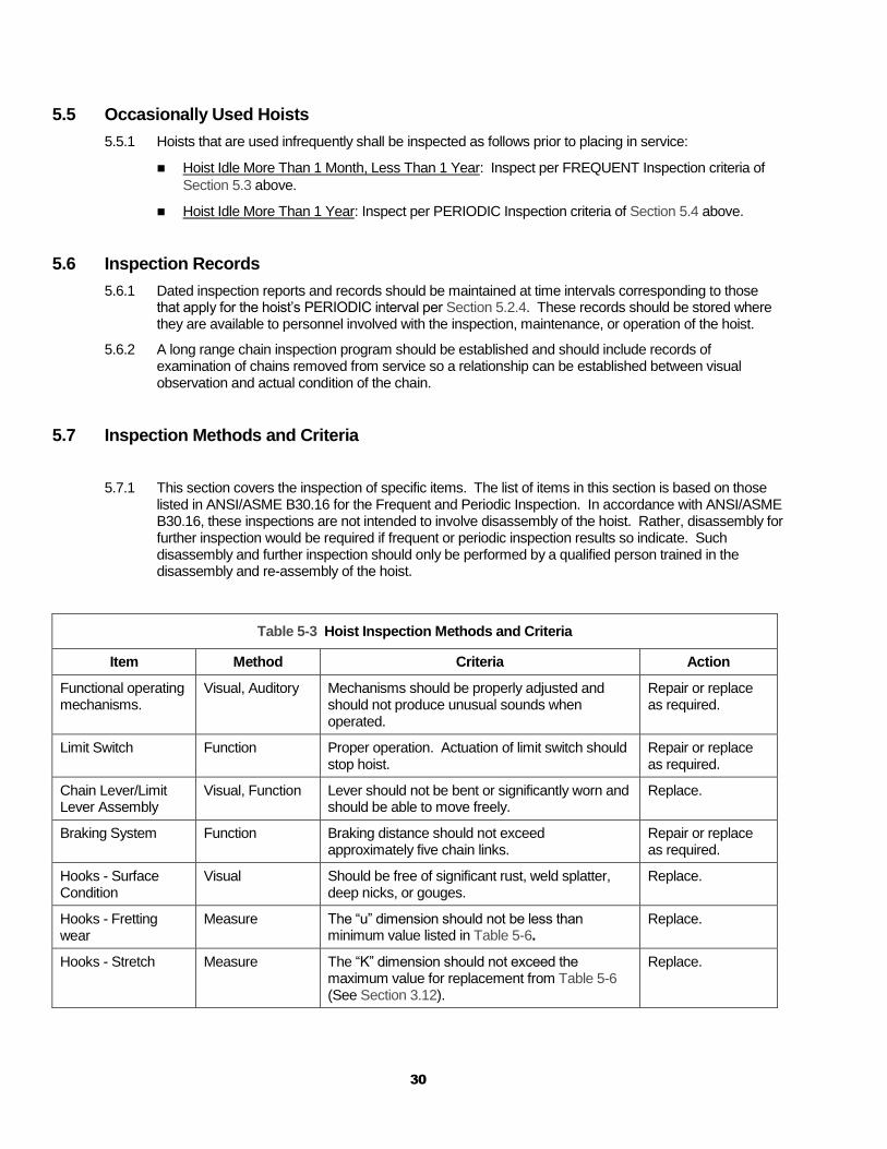
5.7 Inspection Methods and Criteria
5.7.1 This section covers the inspection of specific items. The list of items in this section is based on those listed in ANSI/ASME B30.16 for the Frequent and Periodic Inspection. In accordance with ANSI/ASME B30.16, these inspections are not intended to involve disassembly of the hoist. Rather, disassembly for further inspection would be required if frequent or periodic inspection results so indicate. Such disassembly and further inspection should only be performed by a qualified person trained in the disassembly and re-assembly of the hoist.
Table 5-3 Hoist Inspection Methods and Criteria
Item Method Criteria Action
Functional operating mechanisms.
Visual, Auditory Mechanisms should be properly adjusted and should not produce unusual sounds when operated.
Repair or replace as required.
Limit Switch Function Proper operation. Actuation of limit switch should stop hoist.
Repair or replace as required.
Chain Lever/Limit Lever Assembly
Visual, Function Lever should not be bent or significantly worn and should be able to move freely.
Replace.
Braking System Function Braking distance should not exceed approximately five chain links.
Repair or replace as required.
Hooks - Surface Condition
Visual Should be free of significant rust, weld splatter, deep nicks, or gouges.
Replace.
Hooks - Fretting wear
Measure The “u” dimension should not be less than minimum value listed in Table 5-6.
Replace.
Hooks - Stretch Measure The “K” dimension should not exceed the maximum value for replacement from Table 5-6 (See Section 3.12).
Replace.
31
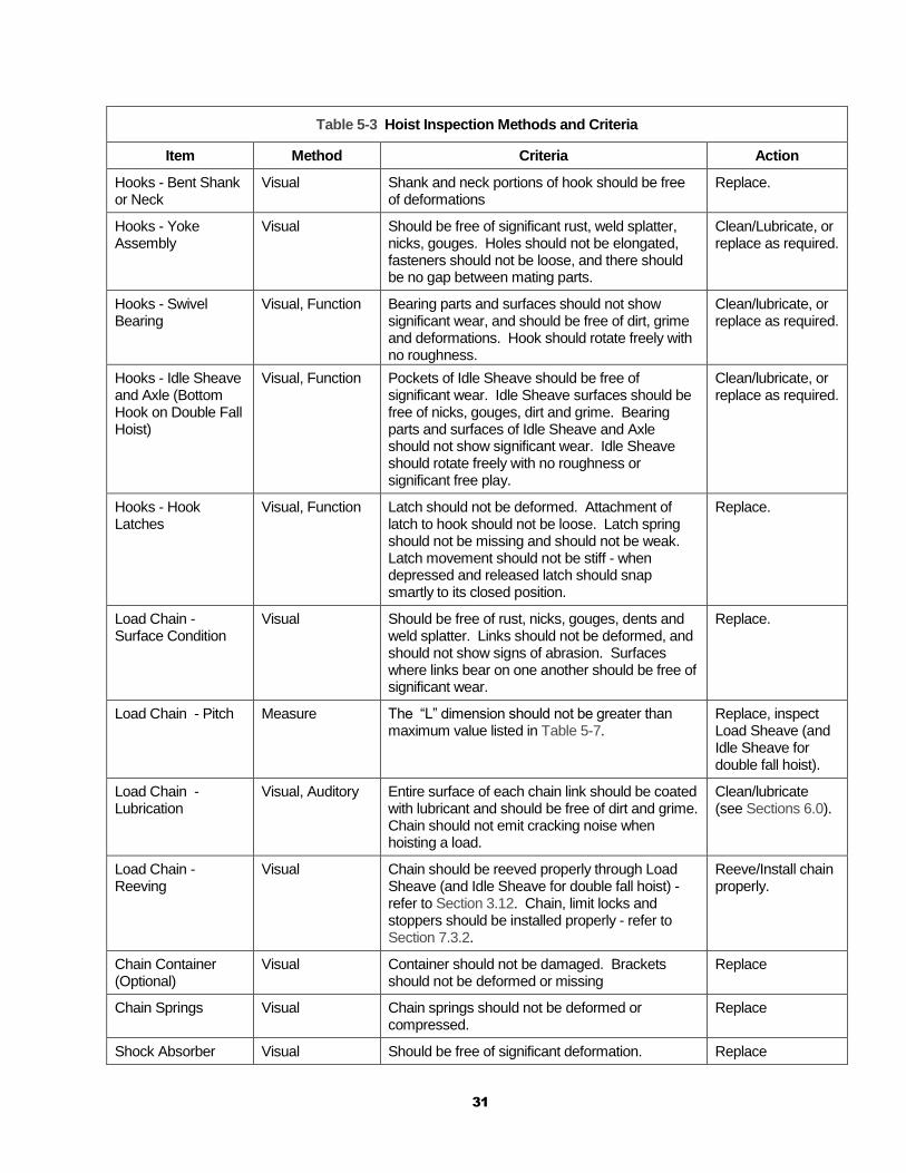
Table 5-3 Hoist Inspection Methods and Criteria
Item Method Criteria Action
Hooks - Bent Shank or Neck
Visual Shank and neck portions of hook should be free of deformations
Replace.
Hooks - Yoke Assembly
Visual Should be free of significant rust, weld splatter, nicks, gouges. Holes should not be elongated, fasteners should not be loose, and there should be no gap between mating parts.
Clean/Lubricate, or replace as required.
Hooks - Swivel Bearing
Visual, Function Bearing parts and surfaces should not show significant wear, and should be free of dirt, grime and deformations. Hook should rotate freely with no roughness.
Clean/lubricate, or replace as required.
Hooks - Idle Sheave and Axle (Bottom Hook on Double Fall Hoist)
Visual, Function Pockets of Idle Sheave should be free of significant wear. Idle Sheave surfaces should be free of nicks, gouges, dirt and grime. Bearing parts and surfaces of Idle Sheave and Axle should not show significant wear. Idle Sheave should rotate freely with no roughness or significant free play.
Clean/lubricate, or replace as required.
Hooks - Hook Latches
Visual, Function Latch should not be deformed. Attachment of latch to hook should not be loose. Latch spring should not be missing and should not be weak. Latch movement should not be stiff - when depressed and released latch should snap smartly to its closed position.
Replace.
Load Chain - Surface Condition
Visual Should be free of rust, nicks, gouges, dents and weld splatter. Links should not be deformed, and should not show signs of abrasion. Surfaces where links bear on one another should be free of significant wear.
Replace.
Load Chain - Pitch Measure The “L” dimension should not be greater than maximum value listed in Table 5-7.
Replace, inspect Load Sheave (and Idle Sheave for double fall hoist).
Load Chain - Lubrication
Visual, Auditory Entire surface of each chain link should be coated with lubricant and should be free of dirt and grime. Chain should not emit cracking noise when hoisting a load.
Clean/lubricate (see Sections 6.0).
Load Chain - Reeving
Visual Chain should be reeved properly through Load Sheave (and Idle Sheave for double fall hoist) - refer to Section 3.12. Chain, limit locks and stoppers should be installed properly - refer to Section 7.3.2.
Reeve/Install chain properly.
Chain Container (Optional)
Visual Container should not be damaged. Brackets should not be deformed or missing
Replace
Chain Springs Visual Chain springs should not be deformed or compressed.
Replace
Shock Absorber Visual Should be free of significant deformation. Replace
32
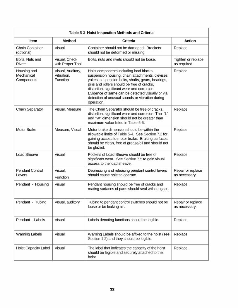
Table 5-3 Hoist Inspection Methods and Criteria
Item Method Criteria Action
Chain Container (optional)
Visual Container should not be damaged. Brackets should not be deformed or missing.
Replace
Bolts, Nuts and Rivets
Visual, Check with Proper Tool
Bolts, nuts and rivets should not be loose. Tighten or replace as required.
Housing and Mechanical Components
Visual, Auditory, Vibration, Function
Hoist components including load blocks, suspension housing, chain attachments, clevises, yokes, suspension bolts, shafts, gears, bearings, pins and rollers should be free of cracks, distortion, significant wear and corrosion. Evidence of same can be detected visually or via detection of unusual sounds or vibration during operation.
Replace
Chain Separator Visual, Measure The Chain Separator should be free of cracks, distortion, significant wear and corrosion. The “L” and "W" dimension should not be greater than maximum value listed in Table 5-5.
Replace
Motor Brake Measure, Visual Motor brake dimension should be within the allowable limits of Table 5-4. See Section 7.2 for gaining access to motor brake. Braking surfaces should be clean, free of grease/oil and should not be glazed.
Replace
Load Sheave Visual Pockets of Load Sheave should be free of significant wear. See Section 7.5 to gain visual access to the load sheave.
Replace.
Pendant Control Levers
Visual,
Function
Depressing and releasing pendant control levers should cause hoist to operate.
Repair or replace as necessary.
Pendant - Housing Visual Pendant housing should be free of cracks and mating surfaces of parts should seal without gaps.
Replace.
Pendant - Tubing Visual, auditory Tubing to pendant control switches should not be loose or be leaking air.
Repair or replace as necessary.
Pendant - Labels Visual Labels denoting functions should be legible. Replace.
Warning Labels Visual Warning Labels should be affixed to the hoist (see Section 1.2) and they should be legible.
Replace
Hoist Capacity Label Visual The label that indicates the capacity of the hoist should be legible and securely attached to the hoist.
Replace.
33
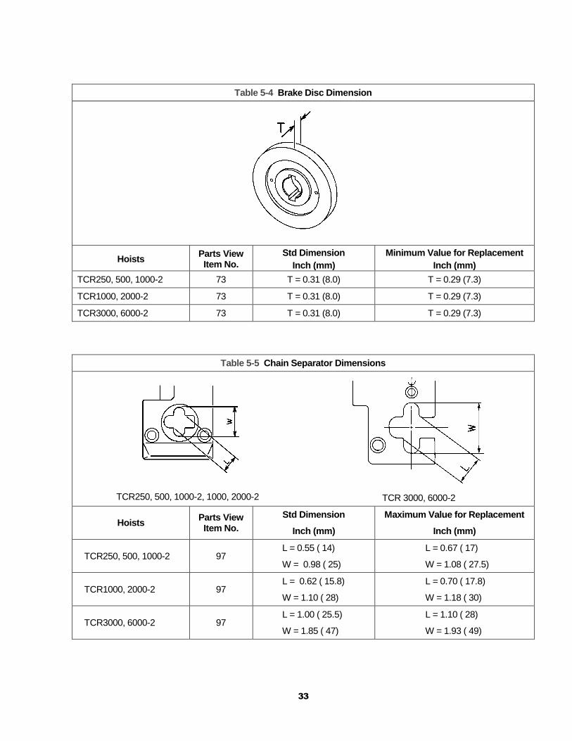
Table 5-4 Brake Disc Dimension
Hoists Parts View Item No.
Std Dimension
Inch (mm)
Minimum Value for Replacement
Inch (mm)
TCR250, 500, 1000-2 73 T = 0.31 (8.0) T = 0.29 (7.3)
TCR1000, 2000-2 73 T = 0.31 (8.0) T = 0.29 (7.3)
TCR3000, 6000-2 73 T = 0.31 (8.0) T = 0.29 (7.3)
Table 5-5 Chain Separator Dimensions
TCR250, 500, 1000-2, 1000, 2000-2
TCR 3000, 6000-2
Hoists Parts View Item No.
Std Dimension
Inch (mm)
Maximum Value for Replacement
Inch (mm)
TCR250, 500, 1000-2 97 L = 0.55 ( 14)
W = 0.98 ( 25)
L = 0.67 ( 17)
W = 1.08 ( 27.5)
TCR1000, 2000-2 97 L = 0.62 ( 15.8)
W = 1.10 ( 28)
L = 0.70 ( 17.8)
W = 1.18 ( 30)
TCR3000, 6000-2 97 L = 1.00 ( 25.5)
W = 1.85 ( 47)
L = 1.10 ( 28)
W = 1.93 ( 49)

34
Table 5-6 Top Hook & Bottom Hook Dimensions
Dimensions K and U should be measured and recorded below prior to any use when the hook is first placed into service.
Hoists Parts View Item No.
Recorded Dimension When New
Maximum/Minimum Value for Replacement
TCR250, 500, 1000-2 115
120
Top Hook K = _______________
Top Hook U = _______________
Bottom Hook K = ____________
Bottom Hook U = ____________ For K if the measured dimension exceeds 1.05 times the recorded new dimension, the hook should be replaced.
For U if the measured dimension is less than .9 times the recorded new dimension, the hook should be replaced.
TCR1000, 2000-2 115
120
Top Hook K = _______________
Top Hook U = _______________
Bottom Hook K = ____________
Bottom Hook U = ____________
TCR3000, 6000-2 115
120
Top Hook K = _______________
Top Hook U = _______________
Bottom Hook K = ____________
Bottom Hook U = ____________
Table 5-7 Chain Dimensions
Hoists Parts View Item No.
Std Nominal Dimension Inch (mm)
Maximum Value for Replacement Inch (mm)
TCR 250, 500, 1000-2 131 Nominal L = 3.76 (95.5) L = 3.82 (96.9)
TCR 1000, 2000-2 131 Nominal L = 4.18 (106.2) L = 4.25 (107.8)
TCR 3000, 6000-2 131 Nominal L = 5.96 (151.5) L = 6.05 (153.8)
35
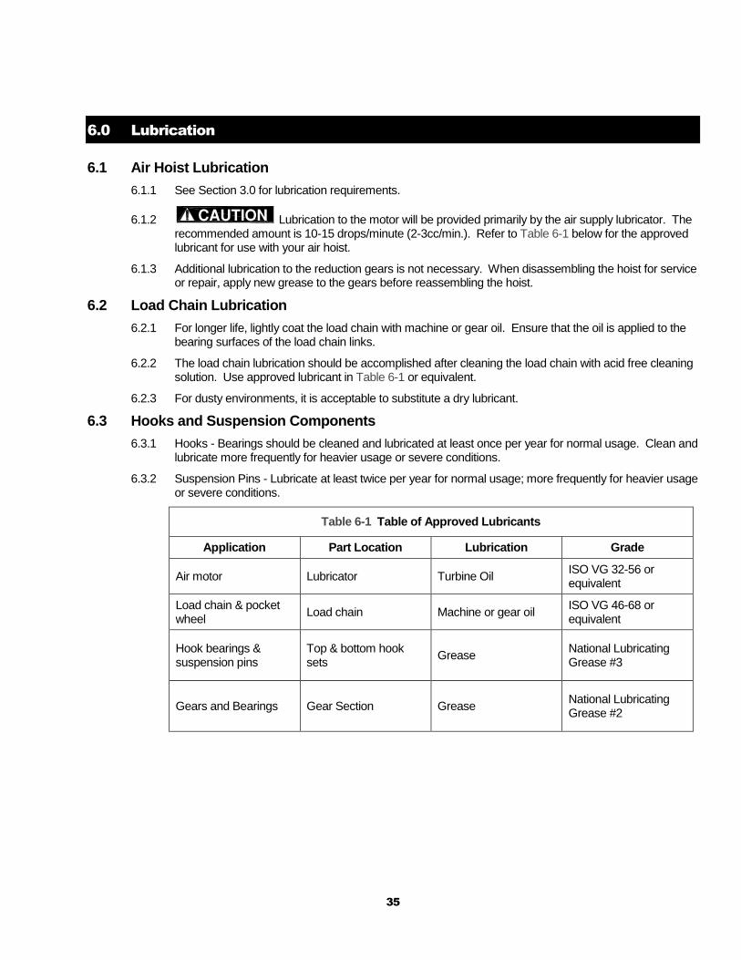
6.0 Lubrication
6.1 Air Hoist Lubrication
6.1.1 See Section 3.0 for lubrication requirements.
6.1.2 Lubrication to the motor will be provided primarily by the air supply lubricator. The recommended amount is 10-15 drops/minute (2-3cc/min.). Refer to Table 6-1 below for the approved lubricant for use with your air hoist.
6.1.3 Additional lubrication to the reduction gears is not necessary. When disassembling the hoist for service or repair, apply new grease to the gears before reassembling the hoist.
6.2 Load Chain Lubrication
6.2.1 For longer life, lightly coat the load chain with machine or gear oil. Ensure that the oil is applied to the bearing surfaces of the load chain links.
6.2.2 The load chain lubrication should be accomplished after cleaning the load chain with acid free cleaning solution. Use approved lubricant in Table 6-1 or equivalent.
6.2.3 For dusty environments, it is acceptable to substitute a dry lubricant.
6.3 Hooks and Suspension Components
6.3.1 Hooks - Bearings should be cleaned and lubricated at least once per year for normal usage. Clean and lubricate more frequently for heavier usage or severe conditions.
6.3.2 Suspension Pins - Lubricate at least twice per year for normal usage; more frequently for heavier usage or severe conditions.
Table 6-1 Table of Approved Lubricants
Application Part Location Lubrication Grade
Air motor Lubricator Turbine Oil ISO VG 32-56 or equivalent
Load chain & pocket wheel
Load chain Machine or gear oil ISO VG 46-68 or equivalent
Hook bearings & suspension pins
Top & bottom hook sets
Grease National Lubricating Grease #3
Gears and Bearings Gear Section Grease National Lubricating Grease #2

36
7.0 Maintenance and Handling
7.1 Load Limiter
7.1.1 The purpose of the load limiter is to prevent using the hoist in an overload situation. When lifting, the hoist will stop automatically if the load is above the rated capacity of the hoist.
7.1.2 The adjustment is factory set to actuate at approximately125% of rated capacity (based on supply air pressure of 90 PSI). Note: the load limiter may need adjustment to compensate for air supply pressures significantly less than 90 PSI.
Figure 7-1 Load Limiter screw adjustment location
7.1.3 Adjustment Procedure
1) Before proceeding with the load limiter adjustment, note the following:
a. Adjusting the load limiter involves operating the hoist. Personnel involved in the adjustment procedure should read, understand, and follow Section 4, "Operation".
b. For the adjustment procedure, the hoist should be connected to an air supply (see Section 3.1) and it should initially be without a load on its hook.
c. Start this procedure with an unloaded hoist. All adjustments to the load limiter should be made with the load in a resting position so that the load chain is not tensioned.
d. For the adjustment procedure: OUT means the counter-clockwise (CCW) direction, and IN means the clockwise (CW) direction.
e. The pressure of the air supply at the hoist’s inlet port (acceptable range is 60 to 90 PSI) affects the performance of your air hoist, including the actuation point of the load limiter. Therefore, ensure that during the adjustment procedure the air pressure at the hoist's inlet port is the same as that which the hoist will experience in normal operation. The relationship between air supply pressure and load limiter actuation is:
for a given load limiter setting, as pressure decreases, the actuation point increases.
37
f. When the load limiter is adjusted and working properly, the hoist will operate and lift the load a short distance before the load limiter automatically stops lifting.
2) Refer to Figure 7-1. Loosen the lock nut and slowly turn the adjustment screw OUT until it is loose and no longer is in contact with the internal load limiter spring – as this occurs the screw should become easier to turn. Stop turning the screw once it is loose and easier to turn.
3) Turn the adjustment screw IN just enough so that it begins to contact the internal load limiter spring – as this occurs the screw should become slightly harder to turn.
4) Put a load equal to the desired actuation point on the hoist's hook (do not exceed 125% of the hoist's rated capacity). Begin to slowly lift the load, then increase the lifting speed. Return the load to its resting position so the load chain is not under tension.
5) If the load limiter prevents lifting, turn the adjustment screw IN one full turn.
6) Repeat steps 4 and 5 until the load limiter allows lifting.
7) Turn the adjustment screw OUT ¾ of a turn.
8) Attempt to lift the rated capacity load again, beginning slowly, then increasing the lifting speed.
9) If the load limiter does not allow lifting, then turn the adjustment screw IN ¼ turn.
10) Repeat steps 8 and 9 until the load limiter allows lifting.
11) Turn the adjustment screw IN ¼ turn. Then, while holding the adjustment screw, tighten the lock nut to secure the setting.
Turning the adjustment screw IN 8 full turns or more will disable the load limiter.
7.2 Brake
7.2.1 The hoist brake is not adjustable.
7.2.2 Inspect the brake disc in accordance with Section 5.7, Table 5-3.
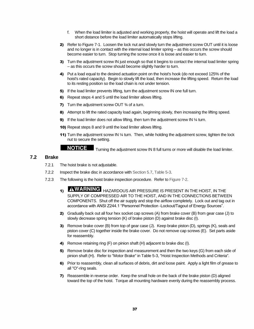
7.2.3 The following is the hoist brake inspection procedure. Refer to Figure 7-2.
1) HAZARDOUS AIR PRESSURE IS PRESENT IN THE HOIST, IN THE
SUPPLY OF COMPRESSED AIR TO THE HOIST, AND IN THE CONNECTIONS BETWEEN
COMPONENTS. Shut off the air supply and stop the airflow completely. Lock out and tag out in
accordance with ANSI Z244.1 “Personnel Protection -Lockout/Tagout of Energy Sources”.
2) Gradually back out all four hex socket cap screws (A) from brake cover (B) from gear case (J) to
slowly decrease spring tension (K) of brake piston (D) against brake disc (I).
3) Remove brake cover (B) from top of gear case (J). Keep brake piston (D), springs (K), seals and
piston cover (C) together inside the brake cover. Do not remove cap screws (E). Set parts aside
for reassembly.
4) Remove retaining ring (F) on pinion shaft (H) adjacent to brake disc (I).
5) Remove brake disc for inspection and measurement and then the two keys (G) from each side of
pinion shaft (H). Refer to "Motor Brake" in Table 5-3, "Hoist Inspection Methods and Criteria".
6) Prior to reassembly, clean all surfaces of debris, dirt and loose paint. Apply a light film of grease to
all "O"-ring seals.
7) Reassemble in reverse order. Keep the small hole on the back of the brake piston (D) aligned
toward the top of the hoist. Torque all mounting hardware evenly during the reassembly process.
38
Figure 7-2 Brake Inspection Diagram
(Note: figure above represents TCR250-2000 model types, larger model types are
similar and the procedure for inspection is identical.)
7.3 Load Chain
7.3.1 Lubrication and Cleaning
Clean the chain with an acid-free cleaning solution. The load chain should be kept clean and
lubricated.
Lubrication - Clean and lubricate the load chain per Section 6 at least once every 3 months for
normal usage. Clean and lubricate more frequently for heavier usage or severe conditions.
7.3.2 Replacement
1) An air supply line must be connected to the hoist in order to perform the
following procedures.
2) Be certain that the replacement chain is obtained from Harrington and is the
exact size, grade and construction as the original chain.
3) When replacing load chain, check for wear on mating parts, i.e. Load Sheave,
Chain Guides and Idler Wheels, and replace parts if necessary. Remove old chain. Remove hook
set assemblies, limit locks, stoppers and end connections from the chain for reuse on new chain. If
the load chain is being replaced due to damage or wear out, prevent its reuse by destroying the old
chain.
39
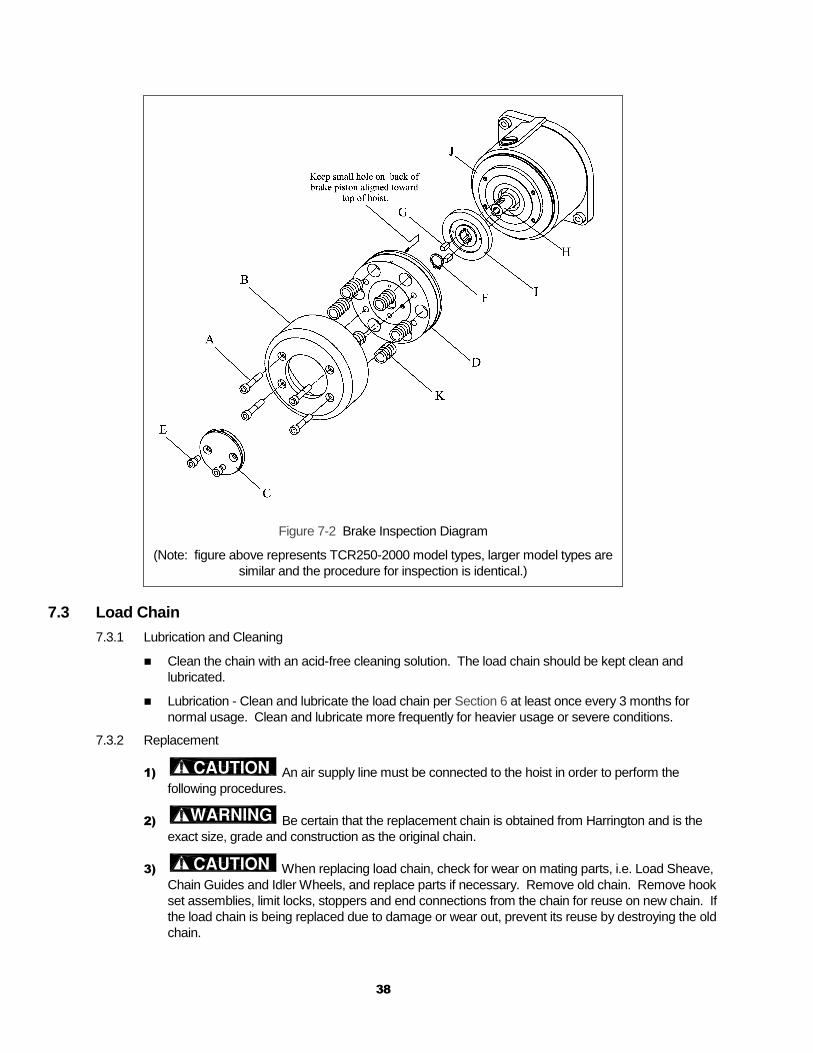
4) Invert the hoist such that the chain separator openings are facing up. The
chain must be inserted into the chain separator on the no load side opening. This is where the no
load end of chain attaches to hoist body. Without inserting the load chain, operate the hoist
pendant or cord control to determine which direction the load sheave is rotating in relation to the
pendant control function pressed or pulled. Install load chain into the hoist making certain the first
link is a standing link and that its weld is facing away from the centerline of the hoist. See Figures
7-3 and 7-4 below.
Figure 7-3 Load Chain Installation Diagram
5) Operate the hoist slowly to catch and pull the chain through the hoist. Make
sure the chain feeds smoothly while operating the hoist. If binding occurs, stop and reverse the
hoist direction to back the chain out. Reinsert the chain while gradually operating the hoist
controls. Continue until sufficient quantity of chain is fed through the hoist.
Table 7-1 Placement of Stoppers on Load Chain
Model Type Hoist Version 1, A & B Version C
Load Side Chain End No Load Side Chain End Load Side Chain End No Load Side Chain End
TCR250P, C
TCR500P, C
TCR1000P, C None 8 None 10
TCR1000P2, C2 8 8 8 10
TCR2000P2, C2 7 8 7 10
TCR3000P, C
TCR6000P2, C2 None None None None
40
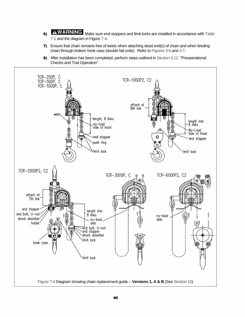
6) Make sure end stoppers and limit locks are installed in accordance with Table
7-1 and the diagram in Figure 7-4.
7) Ensure that chain remains free of twists when attaching dead end(s) of chain and when feeding
chain through bottom hook case (double fall units). Refer to Figures 3-6 and 3-7.
8) After installation has been completed, perform steps outlined in Section 3.12 "Preoperational
Checks and Trial Operation".
Figure 7-4 Diagram showing chain replacement guide – Versions 1, A & B (See Section 10)
41
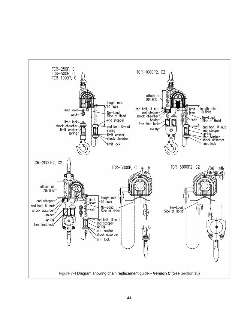
Figure 7-4 Diagram showing chain replacement guide – Version C (See Section 10)

42
7.4 Pendant
7.4.1 The following procedure covers the installation of a pendant control station.
1) Put hose, 3 tubes and wire through the bracket hole. See Figure 7-5.
2) Attach the hose to the bracket by installing the retaining nut to the hose fitting.
3) Torque retaining nut to 20 lbf.-ft.
Figure 7-5
4) Attach the wire cable to the hoist valve body with the screw as shown in Figure 7-6.
5) Torque machine screw to between 30 and 40 in-lbf.
Figure 7-6
6) Attach the three tubes to each nipple as shown in Figure 7-7. Red tube for main air, clear tube for lifting and black tube for lowering.
Versions 1 & A
Versions B & C
Figure 7-7
When attaching tubes take care not to bend or kink tubing. This will result in the air flow being restricted and poor response to the pendant controls.

43
7.5 Load Sheave Inspection
7.5.1 Perform this inspection by removing the chain separator and viewing the load sheave while operating
the hoist slowly, with no load, and in accordance with Section 4 “Operation”. Refer to Figure 7-8 and
remove the chain separator as follows.
TCR3000 and TCR6000-2: The chain separator can be removed by removing the shaft retaining
ring from its groove on the limit lever shaft adjacent to the valve section, sliding the limit lever
assembly away from the chain separator, and removing the two larger outboard hex socket screws
holding the chain separator to the hoist body.
TCR250 through TCR2000-2: The chain separator can be removed by removing the shaft
retaining ring from its groove on the limit lever shaft adjacent to the valve section, sliding the limit
lever assembly away from the chain separator, removing the limit lever from the limit lever shaft,
and removing the hex socket screws holding the chain separator to the hoist body.
Figure 7-8 Chain Separator Removal
7.6 Storage
7.6.1 Whenever the hoist is to be placed into storage, place extra lubricating oil into the air inlet opening and circulate the air motor before plugging the inlet. Make certain that no debris, dirt or moisture is allowed to enter the air hoist through air inlet opening during preparations for storage.
7.6.2 The storage location should be clean and dry.
7.7 Outdoor Installation
7.7.1 For hoist installations that are outdoors, the hoist should be covered when not in use.
7.7.2 In order to prevent internal corrosion from occurring, the hoist must be operated using proper quality air at least once per week by raising and lowering the hoist one full cycle. Note: the possibility of corrosion in the valve section of the hoist increases for areas where salt air and high humidity are present. For such situations you may need to operate your hoist more often than once per week.

44
8.0 Troubleshooting
HAZARDOUS AIR PRESSURE IS PRESENT IN THE HOIST, IN THE SUPPLY OF COMPRESSED AIR TO THE HOIST, AND IN CONNECTIONS BETWEEN COMPONENTS.
Before performing ANY maintenance on the equipment, de-energize the supply of compressed air to the equipment, and lock and tag the supply device in the de-energized position. Refer to ANSI Z244.1, “Personnel Protection - Lockout/Tagout of Energy Sources.”
Only Trained and competent personnel should inspect and repair this equipment.
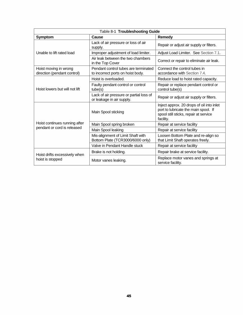
Table 8-1 Troubleshooting Guide
Symptom Cause Remedy
Does not operate
Lack of air pressure or loss of air supply.
Repair or adjust air supply or filters.
Seizure of Main Spool, Brake Spool, or Air Motor.
Repair at service facility.
Seizure of brake or brake mechanism fails to release.
Repair at service facility.
Bending or crimping of pendant hose or control tubes
Correct or repair bend or crimp in hose and/or tubes
Air leak between the two chambers in the Top Cover
Correct or repair to eliminate air leak.
Hoist is overloaded. Reduce the load to the rated capacity of hoist.
Lifting speed is slow
Low air pressure at hoist inlet port. Repair or adjust air supply or filters. Check for air line obstruction.
Air supply hose or piping is too small. Replace hose or piping sizes with recommended sizes in Section 3.0.
Malfunction of brake. Repair at service facility.
Bending or crimping of pendant hoses or control tubes
Correct or repair the bend or crimp in hose and/or control tubes
Lack of sufficient oil in air supply to hoist
Increase oil in air supply to hoist in accordance with requirements in Section 3.0.
Exhaust Silencer or Nylon Silencer clogged
Clean or replace.
Air flow capacity of compressed air system insufficient
Increase air flow capacity of compressed air system to requirements in Section 2.0.
Air motor vanes or bearings worn Repair at service facility.
Air supply to hoist contains dirt or debris
Filter the air supply to the hoist in accordance with the requirements in Section 3.0.
Air leak between the two chambers in the Top Cover
Correct or repair to eliminate air leak.
45
Table 8-1 Troubleshooting Guide
Symptom Cause Remedy
Unable to lift rated load
Lack of air pressure or loss of air supply.
Repair or adjust air supply or filters.
Improper adjustment of load limiter. Adjust Load Limiter. See Section 7.1.
Air leak between the two chambers in the Top Cover
Correct or repair to eliminate air leak.
Hoist moving in wrong direction (pendant control)
Pendant control tubes are terminated to incorrect ports on hoist body.
Connect the control tubes in accordance with Section 7.4.
Hoist lowers but will not lift
Hoist is overloaded. Reduce load to hoist rated capacity.
Faulty pendant control or control tube(s)
Repair or replace pendant control or control tube(s)
Lack of air pressure or partial loss of or leakage in air supply.
Repair or adjust air supply or filters.
Hoist continues running after pendant or cord is released
Main Spool sticking
Inject approx. 20 drops of oil into inlet port to lubricate the main spool. If spool still sticks, repair at service facility.
Main Spool spring broken Repair at service facility
Main Spool leaking Repair at service facility
Mis-alignment of Limit Shaft with Bottom Plate (TCR3000/6000 only)
Loosen Bottom Plate and re-align so that Limit Shaft operates freely.
Valve in Pendant Handle stuck Repair at service facility
Hoist drifts excessively when hoist is stopped
Brake is not holding. Repair brake at service facility.
Motor vanes leaking. Replace motor vanes and springs at service facility.

46
9.0 Warranty
Warranty explanation and terms.
All products sold by Harrington Hoists, Inc. are warranted to be free from defects in material and workmanship from date of shipment by Harrington for the following periods:
1 year – Electric and Air Powered Hoists (excluding (N)ER2 Enhanced Features
Models), Powered Trolleys, Powered Tiger Track Jibs and Gantries,
Crane Components, Below the Hook Devices, Spare / Replacement Parts
2 years – Manual Hoists & Trolleys, Beam Clamps
3 years – (N)ER2 Enhanced Features Model Hoists
5 years – Manual Tiger Track Jibs and Gantries, TNER Pull - Rotor Motor Brake
10 years – (N)ER2 “The Guardian” Smart Brake
The product must be used in accordance with manufacturer’s recommendations and must not
have been subject to abuse, lack of maintenance, misuse, negligence, or unauthorized repairs or alterations.
Should any defect in material or workmanship occur during the above time period in any product, as determined by Harrington Hoist’s inspection of the product, Harrington Hoists, Inc. agrees, at its discretion, either to replace (not including installation) or repair the part or product free of charge and deliver said item F.O.B. Harrington Hoists, Inc. place of business to customer.
Customer must obtain a Return Goods Authorization as directed by Harrington or Harrington’s published repair center prior to shipping product for warranty evaluation. An explanation of the complaint must accompany the product. Product must be returned freight prepaid. Upon repair, the product will be covered for the remainder of the original warranty period. Replacement parts installed after the original warranty period will only be eligible for replacement (not including installation) for a period of one year from the installation date. If it is determined there is no defect, or that the defect resulted from causes not within the scope of Harrington’s warranty, the customer will be responsible for the costs of returning the product.
Harrington Hoists, Inc. disclaims any and all other warranties of any kind expressed or implied as to the product’s merchantability or fitness for a particular application. Harrington will not be liable for death, injuries to persons or property or for incidental, contingent, special or consequential damages, loss or expense arising in connection with the use or inability whatever, regardless of whether damage, loss or expense results from any act or failure to act by Harrington, whether negligent or willful, or from any other reason.
47
10.0 Parts List
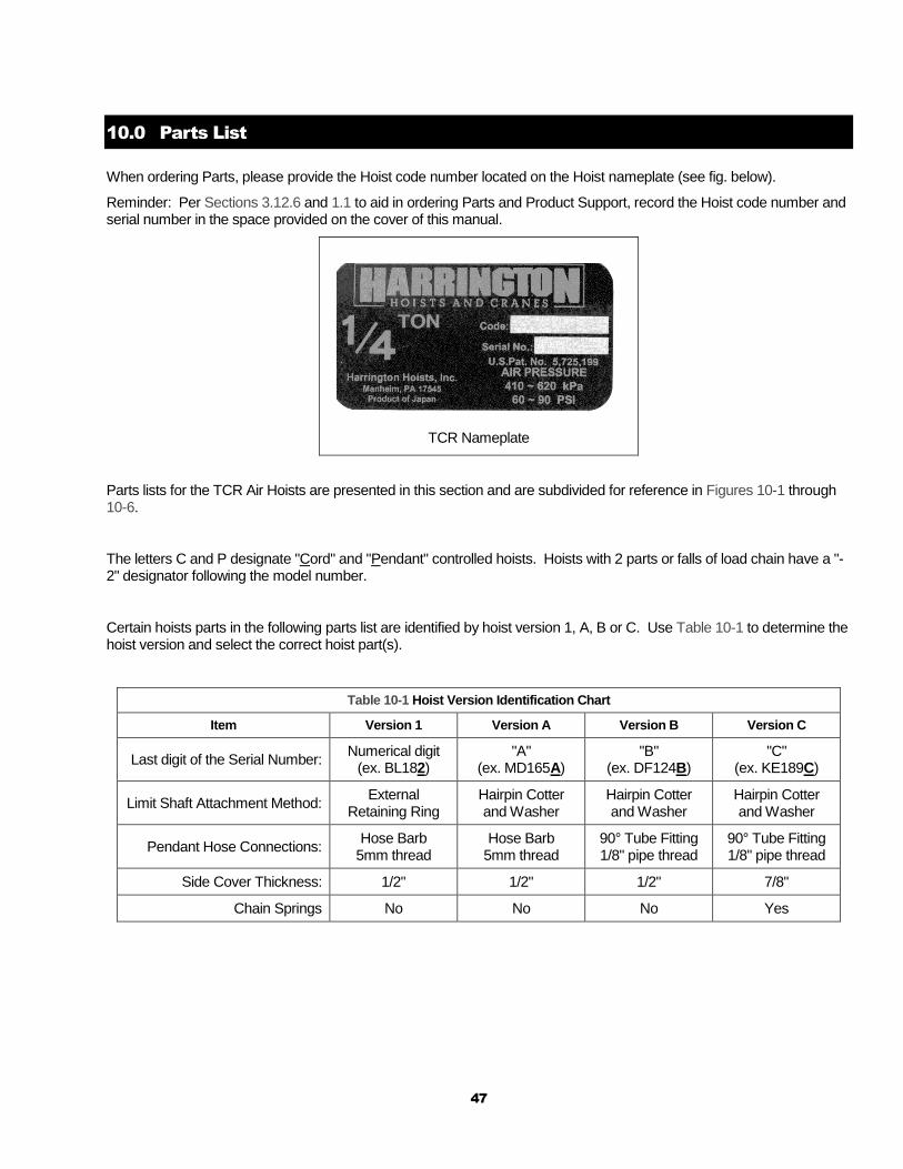
When ordering Parts, please provide the Hoist code number located on the Hoist nameplate (see fig. below).
Reminder: Per Sections 3.12.6 and 1.1 to aid in ordering Parts and Product Support, record the Hoist code number and serial number in the space provided on the cover of this manual.
TCR Nameplate
Parts lists for the TCR Air Hoists are presented in this section and are subdivided for reference in Figures 10-1 through 10-6.
The letters C and P designate "Cord" and "Pendant" controlled hoists. Hoists with 2 parts or falls of load chain have a "-2" designator following the model number.
Certain hoists parts in the following parts list are identified by hoist version 1, A, B or C. Use Table 10-1 to determine the hoist version and select the correct hoist part(s).
Table 10-1 Hoist Version Identification Chart
Item Version 1 Version A Version B Version C
Last digit of the Serial Number: Numerical digit
(ex. BL182) "A"
(ex. MD165A) "B"
(ex. DF124B) "C"
(ex. KE189C)
Limit Shaft Attachment Method: External
Retaining Ring Hairpin Cotter and Washer
Hairpin Cotter and Washer
Hairpin Cotter and Washer
Pendant Hose Connections: Hose Barb
5mm thread Hose Barb
5mm thread 90° Tube Fitting 1/8" pipe thread
90° Tube Fitting 1/8" pipe thread
Side Cover Thickness: 1/2" 1/2" 1/2" 7/8"
Chain Springs No No No Yes

Figure 10-1 TCR250 / TCR500 Main Body
10
.1
Ma
in B
od
y
10.1
.1
TC
R250 / T
CR
500 M
ain
Body
48
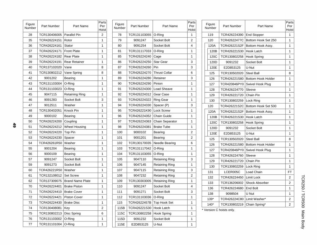
Figure Number
Part Number Part Name Parts Per
Hoist
28 TCR130406005 Parallel Pin 2
35 TCR426224151 Rotor 1
36 TCR426224161 Stator 1
37 TCR426224171 Front Plate 1
38 TCR426224182 Rear Plate 1
39 TCR426224191 Rear Retainer 1
40 TCR137102020 Vane 8
41 TCR130802212 Vane Spring 8
42 9001202 Bearing 1
43 TCR131103004 O-Ring 1
44 TCR131103023 O-Ring 1
45 9047115 Retaining Ring 1
46 9091283 Socket Bolt 3
47 9012511 Washer 1
48 TCR130402051 Knock Pin 1
49 9000102 Bearing 1
50 TCR426224200 Coupling 1
51 TCR426224212 Wheel Housing 1
52 TCR426224220 Top Pin 1
53 TCR426224230 Spacer 1
54 TCR426261R50 Washer 1
55 9001204 Bearing 1
56 9000109 Bearing 1
57 9091247 Socket Bolt 1
59 9091273 Socket Bolt 1
60 TCR426221R50 Washer 1
61 TCR132108012 Set Screw 1
62 TCR137309075 Brand Name Plate 1
70 TCR426224401 Brake Piston 1
71 TCR426224410 Brake Cover 1
72 TCR426224421 Piston Cover 1
73 TCR426224430 Brake Disc 1
74 TCR130408081 Key 2
75 TCR130802213 Disc Spring 6
76 TCR131103002 O-Ring 1
77 TCR131101004 O-Ring 1
Figure Number
Part Number Part Name Parts Per
Hoist
78 TCR131103055 O-Ring 1
79 9091247 Socket Bolt 2
80 9091254 Socket Bolt 4
81 TCR131117033 O-Ring 1
85 TCR426224240 Cage 1
86 TCR426224250 Star Gear 3
87 TCR426224260 Pin 3
88 TCR426224270 Thrust Collar 6
89 TCR426224280 Retainer 3
90 TCR426224290 Pinion 1
91 TCR426224300 Load Sheave 1
92 TCR426224312 Gear Case 1
93 TCR426224322 Ring Gear 1
94 TCR426224330 Spacer (P) 3
95 TCR426221K90 Lock Screw 1
96 TCR426224352 Chain Guide 1
97 TCR426224363 Chain Separator 1
98 TCR426224381 Brake Tube 1
100 9000102 Bearing 2
101 9001201 Bearing 2
102 TCR130170035 Needle Bearing 6
103 TCR131117042 O-Ring 1
104 TCR131103055 O-Ring 1
105 9047110 Retaining Ring 3
106 9047145 Retaining Ring 1
107 9047115 Retaining Ring 3
108 9047232 Retaining Ring 2
109 TCR130303005 Retaining Ring 1
110 9091247 Socket Bolt 4
111 9091271 Socket Bolt 3
112 TCR131103036 O-Ring 1
115 TCR42622457B Top Hook Set 1
115B TCR426221S30 Hook Latch 1
115C TCR130802258 Hook Spring 1
115D 9091232 Socket Bolt 1
115E E2D853125 U-Nut 1
Figure Number
Part Number Part Name Parts Per
Hoist
119 TCR426224390 End Stopper 1
120 TCR42622477C Bottom Hook Set 250 1
120A TCR426221S2F Bottom Hook Assy. 1
120B TCR426221S30 Hook Latch 1
120C TCR130802258 Hook Spring 1
120D 9091232 Socket Bolt 1
120E E2D853125 U-Nut 1
125 TCR130502020 Steel Ball 8
126 TCR426221S80 Bottom Hook Holder 1
127 TCR420846PY0 Swivel Hook Plug 1
128 TCR426224770 Sleeve 1
129 TCR426221T20 Chain Pin 1
130 TCR130802259 Lock Ring 1
120 TCR426221S2C Bottom Hook Set 500 1
120A TCR426221S2F Bottom Hook Assy. 1
120B TCR426221S30 Hook Latch 1
120C TCR130802258 Hook Spring 1
120D 9091232 Socket Bolt 1
120E E2D853125 U-Nut 1
125 TCR130502020 Steel Ball 8
126 TCR426221S80 Bottom Hook Holder 1
127 TCR420846PY0 Swivel Hook Plug 1
128 TCR426224760 Sleeve 1
129 TCR426221T20 Chain Pin 1
130 TCR130802259 Lock Ring 1
131 LCER005C Load Chain FT
132 TCR426224450 Limit Lock 2
133 TCR136206002 Shock Absorber 2
136 TCR426224680 End Bolt 1
138 9098504 U Nut 1
139* TCR426224C80 Limit Washer* 2
140* TCR130802219 Chain Spring* 2
* Version C hoists only.
TC
R250 / T
CR
500 M
ain
Body
49

Figure 10-2 TCR1000-2 Main Body
10.1
.2 T
CR
10
00
-2 M
ain
Body
50

Figure Number
Part Number Part Name Parts Per
Hoist
28 TCR130406005 Parallel Pin 2
35 TCR426224151 Rotor 1
36 TCR426224161 Stator 1
37 TCR426224171 Front Plate 1
38 TCR426224182 Rear Plate 1
39 TCR426224191 Rear Retainer 1
40 TCR137102020 Vane 8
41 TCR130802212 Vane Spring 8
42 9001202 Bearing 1
43 TCR131103004 O-Ring 1
44 TCR131103023 O-Ring 1
45 9047115 Retaining Ring 1
46 9091283 Socket Bolt 3
47 9012511 Washer 1
48 TCR130402051 Knock Pin 1
49 9000102 Ball Bearing 1
50 TCR426224200 Coupling 1
51 TCR426224212 Wheel Housing 1
52 TCR426224220 Top Pin 1
53 TCR426224230 Spacer 1
54 TCR426261R50 Washer 1
55 9001204 Bearing 1
56 9000109 Bearing 1
57 9091247 Socket Bolt 1
59 9091273 Socket Bolt 1
60 TCR426221R50 Washer 1
61 TCR132108012 Set Screw 1
62 TCR137309075 Brand Name Plate 1
70 TCR426224401 Brake Piston 1
71 TCR426224410 Brake Cover 1
72 TCR426224421 Piston Cover 1
73 TCR426224430 Brake Disc 1
74 TCR130408081 Key 2
75 TCR130802213 Disc Spring 6
76 TCR131103002 O-Ring 1
77 TCR131101004 O-Ring 1
Figure Number
Part Number Part Name Parts Per
Hoist
78 TCR131103055 O-Ring 1
79 9091247 Socket Bolt 2
80 9091254 Socket Bolt 4
81 TCR131117033 O-Ring 1
85 TCR426224240 Cage 1
86 TCR426224250 Star Gear 3
87 TCR426224260 Pin 3
88 TCR426224270 Thrust Collar 6
89 TCR426224280 Retainer 3
90 TCR426224290 Pinion 1
91 TCR426224300 Load Sheave 1
92 TCR426224312 Gear Case 1
93 TCR426224322 Ring Gear 1
94 TCR426224330 Spacer (P) 3
95 TCR426221K90 Lock Screw 1
96 TCR426224352 Chain Guide 1
97 TCR426224363 Chain Separator 1
98 TCR426224381 Brake Tube 1
100 9000102 Bearing 2
101 9001201 Bearing 2
102 TCR130170035 Needle Bearing 6
103 TCR131117042 O-Ring 1
104 TCR131103055 O-Ring 1
105 9047110 Retaining Ring 3
106 9047145 Retaining Ring 1
107 9047115 Retaining Ring 3
108 9047232 Retaining Ring 2
109 TCR130303005 Retaining Ring 1
110 9091247 Socket Bolt 4
111 9091271 Socket Bolt 3
112 TCR131103036 O-Ring 1
115 TCR42624457H Top Hook Set 1
115B TCR426221S30 Hook Latch 1
115C TCR130802258 Hook Spring 1
115D 9091232 Socket Bolt 1
115E E2D853125 U-Nut 1
Figure Number
Part Number Part Name Parts Per
Hoist
115H TCR426244580 Chain Pin 1
115J 9012511 Washer 1
115K 9098504 U Nut 1
116 TCR426244630 Free Limit Lock 1
118 TCR426244620 Holder 1
119 TCR426224390 End Stopper 2
120 TCR426244S2C Bottom Hook Set 1
120A TCR426221S2F Bottom Hook Assy. 1
120B TCR426221S30 Hook Latch 1
120C TCR130802258 Hook Spring 1
120D 9091232 Socket Bolt 1
120E E2D853125 U-Nut 1
121 TCR130172006 Needle Bearing 1
122 TCR131204014 Oil Seal 2
125 TCR130502020 Steel Ball 8
126 TCR426244590 Bottom Yoke Assy. 1
127 TCR420846PY0 Swivel Hook Plug 1
128 TCR420846PW0 Outer Bearing Race 1
129 TCR426244600 Wheel Shaft 1
130 TCR426241U20 Idle Sheave 1
135 9091253 Socket Bolt 2
137 9098504 U Nut 2
139 9047114 Retaining Ring 1
131 LCER005C Load Chain FT
132 TCR426224450 Limit Lock 1
133 TCR136206002 Shock Absorber 2
136 TCR426224680 End Bolt 2
138 9098504 U Nut 2
139* TCR426224C80 Limit Washer* 1
140* TCR130802219 Chain Spring* 3
* Version C hoists only.
TC
R100
0-2
Main
Body
51
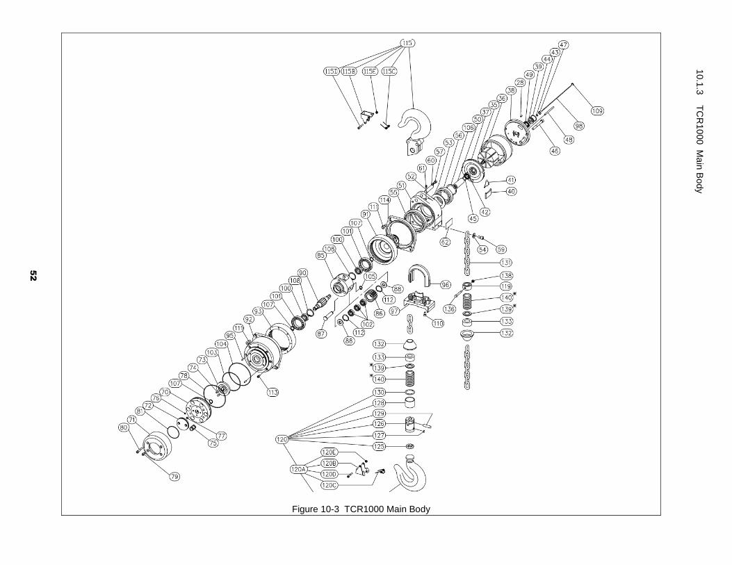
Figure 10-3 TCR1000 Main Body
10.1
.3 T
CR
10
00 M
ain
Body
52
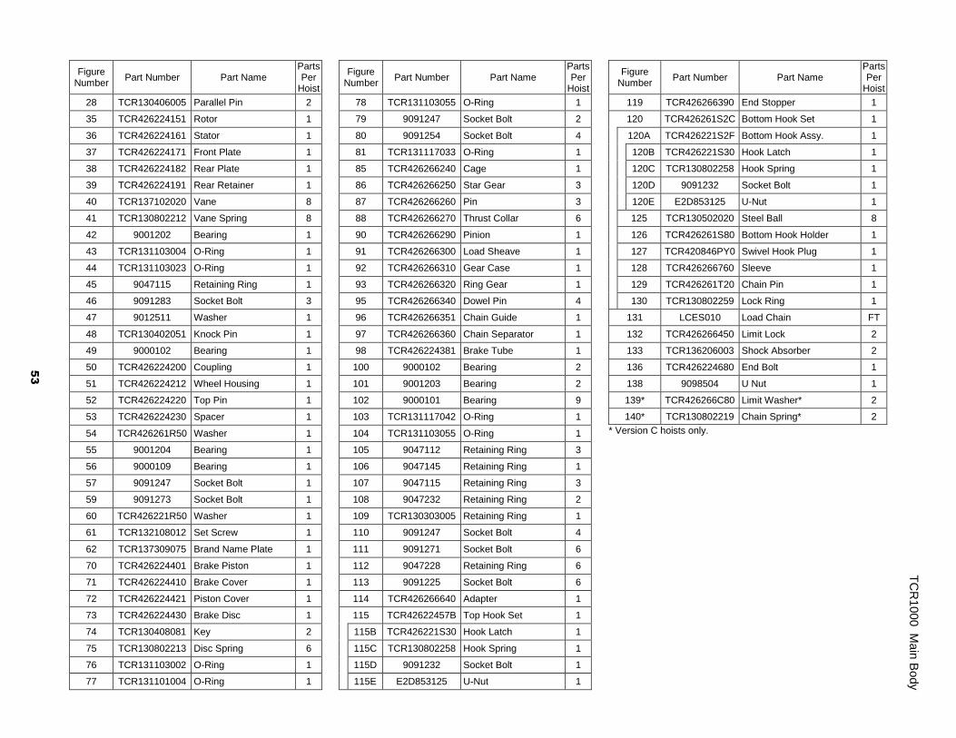
Figure Number
Part Number Part Name Parts Per
Hoist
28 TCR130406005 Parallel Pin 2
35 TCR426224151 Rotor 1
36 TCR426224161 Stator 1
37 TCR426224171 Front Plate 1
38 TCR426224182 Rear Plate 1
39 TCR426224191 Rear Retainer 1
40 TCR137102020 Vane 8
41 TCR130802212 Vane Spring 8
42 9001202 Bearing 1
43 TCR131103004 O-Ring 1
44 TCR131103023 O-Ring 1
45 9047115 Retaining Ring 1
46 9091283 Socket Bolt 3
47 9012511 Washer 1
48 TCR130402051 Knock Pin 1
49 9000102 Bearing 1
50 TCR426224200 Coupling 1
51 TCR426224212 Wheel Housing 1
52 TCR426224220 Top Pin 1
53 TCR426224230 Spacer 1
54 TCR426261R50 Washer 1
55 9001204 Bearing 1
56 9000109 Bearing 1
57 9091247 Socket Bolt 1
59 9091273 Socket Bolt 1
60 TCR426221R50 Washer 1
61 TCR132108012 Set Screw 1
62 TCR137309075 Brand Name Plate 1
70 TCR426224401 Brake Piston 1
71 TCR426224410 Brake Cover 1
72 TCR426224421 Piston Cover 1
73 TCR426224430 Brake Disc 1
74 TCR130408081 Key 2
75 TCR130802213 Disc Spring 6
76 TCR131103002 O-Ring 1
77 TCR131101004 O-Ring 1
Figure Number
Part Number Part Name Parts Per
Hoist
78 TCR131103055 O-Ring 1
79 9091247 Socket Bolt 2
80 9091254 Socket Bolt 4
81 TCR131117033 O-Ring 1
85 TCR426266240 Cage 1
86 TCR426266250 Star Gear 3
87 TCR426266260 Pin 3
88 TCR426266270 Thrust Collar 6
90 TCR426266290 Pinion 1
91 TCR426266300 Load Sheave 1
92 TCR426266310 Gear Case 1
93 TCR426266320 Ring Gear 1
95 TCR426266340 Dowel Pin 4
96 TCR426266351 Chain Guide 1
97 TCR426266360 Chain Separator 1
98 TCR426224381 Brake Tube 1
100 9000102 Bearing 2
101 9001203 Bearing 2
102 9000101 Bearing 9
103 TCR131117042 O-Ring 1
104 TCR131103055 O-Ring 1
105 9047112 Retaining Ring 3
106 9047145 Retaining Ring 1
107 9047115 Retaining Ring 3
108 9047232 Retaining Ring 2
109 TCR130303005 Retaining Ring 1
110 9091247 Socket Bolt 4
111 9091271 Socket Bolt 6
112 9047228 Retaining Ring 6
113 9091225 Socket Bolt 6
114 TCR426266640 Adapter 1
115 TCR42622457B Top Hook Set 1
115B TCR426221S30 Hook Latch 1
115C TCR130802258 Hook Spring 1
115D 9091232 Socket Bolt 1
115E E2D853125 U-Nut 1
Figure Number
Part Number Part Name Parts Per
Hoist
119 TCR426266390 End Stopper 1
120 TCR426261S2C Bottom Hook Set 1
120A TCR426221S2F Bottom Hook Assy. 1
120B TCR426221S30 Hook Latch 1
120C TCR130802258 Hook Spring 1
120D 9091232 Socket Bolt 1
120E E2D853125 U-Nut 1
125 TCR130502020 Steel Ball 8
126 TCR426261S80 Bottom Hook Holder 1
127 TCR420846PY0 Swivel Hook Plug 1
128 TCR426266760 Sleeve 1
129 TCR426261T20 Chain Pin 1
130 TCR130802259 Lock Ring 1
131 LCES010 Load Chain FT
132 TCR426266450 Limit Lock 2
133 TCR136206003 Shock Absorber 2
136 TCR426224680 End Bolt 1
138 9098504 U Nut 1
139* TCR426266C80 Limit Washer* 2
140* TCR130802219 Chain Spring* 2
* Version C hoists only.
TC
R100
0 M
ain
Body
53

Figure 10-4 TCR2000-2 Main Body
10.1
.4 T
CR
20
00
-2 M
ain
Body
54
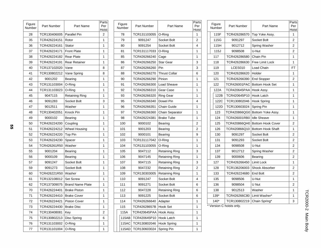
Figure Number
Part Number Part Name Parts Per
Hoist
28 TCR130406005 Parallel Pin 2
35 TCR426224151 Rotor 1
36 TCR426224161 Stator 1
37 TCR426224171 Front Plate 1
38 TCR426224182 Rear Plate 1
39 TCR426224191 Rear Retainer 1
40 TCR137102020 Vane 8
41 TCR130802212 Vane Spring 8
42 9001202 Bearing 1
43 TCR131103004 O-Ring 1
44 TCR131103023 O-Ring 1
45 9047115 Retaining Ring 1
46 9091283 Socket Bolt 3
47 9012511 Washer 1
48 TCR130402051 Knock Pin 1
49 9000102 Bearing 1
50 TCR426224200 Coupling 1
51 TCR426224212 Wheel Housing 1
52 TCR426224220 Top Pin 1
53 TCR426224230 Spacer 1
54 TCR426261R50 Washer 1
55 9001204 Bearing 1
56 9000109 Bearing 1
57 9091247 Socket Bolt 1
59 9091273 Socket Bolt 1
60 TCR426221R50 Washer 1
61 TCR132108012 Set Screw 1
62 TCR137309075 Brand Name Plate 1
70 TCR426224401 Brake Piston 1
71 TCR426224410 Brake Cover 1
72 TCR426224421 Piston Cover 1
73 TCR426224430 Brake Disc 1
74 TCR130408081 Key 2
75 TCR130802213 Disc Spring 6
76 TCR131103002 O-Ring 1
77 TCR131101004 O-Ring 1
Figure Number
Part Number Part Name Parts Per
Hoist
78 TCR131103055 O-Ring 1
79 9091247 Socket Bolt 2
80 9091254 Socket Bolt 4
81 TCR131117033 O-Ring 1
85 TCR426266240 Cage 1
86 TCR426266250 Star Gear 3
87 TCR426266260 Pin 3
88 TCR426266270 Thrust Collar 6
90 TCR426266290 Pinion 1
91 TCR426266300 Load Sheave 1
92 TCR426266310 Gear Case 1
93 TCR426266320 Ring Gear 1
95 TCR426266340 Dowel Pin 4
96 TCR426266351 Chain Guide 1
97 TCR426266360 Chain Separator 1
98 TCR426224381 Brake Tube 1
100 9000102 Bearing 2
101 9001203 Bearing 2
102 9000101 Bearing 9
103 TCR131117042 O-Ring 1
104 TCR131103055 O-Ring 1
105 9047112 Retaining Ring 3
106 9047145 Retaining Ring 1
107 9047115 Retaining Ring 3
108 9047232 Retaining Ring 2
109 TCR130303005 Retaining Ring 1
110 9091247 Socket Bolt 4
111 9091271 Socket Bolt 6
112 9047228 Retaining Ring 6
113 9091225 Socket Bolt 6
114 TCR426266640 Adapter 1
115 TCR42628657B Hook Set 1
115A TCR420645PAA Hook Assy. 1
115AB TCR420645P10 Hook Latch 1
115AC TCR130802046 Hook Spring 1
115AD TCR130603024 Spring Pin 1
Figure Number
Part Number Part Name Parts Per
Hoist
115F TCR426286570 Top Yoke Assy. 1
115G 9091297 Socket Bolt 2
115H 9012712 Spring Washer 2
115J 9098508 U-Nut 2
117 TCR426286580 Chain Pin 1
118 TCR426286630 Free Limit Lock 1
119 LCES010 Load Chain FT
120 TCR426286620 Holder 1
121 TCR426266390 End Stopper 2
122 TCR426001PAC Bottom Hook Set 1
122A TCR420645PAA Hook Assy. 1
122B TCR420645P10 Hook Latch 1
122C TCR130802046 Hook Spring 1
122D TCR130603024 Spring Pin 1
123 TCR420866QG0 Bottom Yoke Assy. 1
124 TCR426001RB0 Idle Sheave 1
125 TCR420866QH0 Bottom Hook Cover 2
126 TCR420866Q10 Bottom Hook Shaft 1
130 9091297 Socket Bolt 2
131 9091293 Socket Bolt 2
134 9098508 U-Nut 2
137 9012712 Spring Washer 2
139 9000606 Bearing 2
127 TCR426266450 Limit Lock 1
128 TCR136206003 Shock Absorber 2
133 TCR426224680 End Bolt 2
135 9098506 U-Nut 1
136 9098504 U Nut 2
138 9012513 Washer 1
139* TCR426266C80 Limit Washer* 1
140* TCR130802219 Chain Spring* 3
* Version C hoists only.
55
TC
R200
0-2
Main
Body

Figure 10-5 TCR3000 Main Body
10.1
.5 T
CR
30
00 M
ain
Body
56
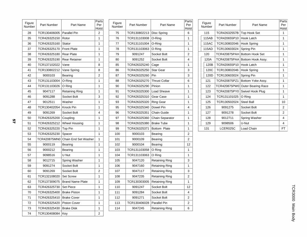
Figure Number
Part Number Part Name Parts Per
Hoist
28 TCR130406005 Parallel Pin 2
35 TCR426325150 Rotor 1
36 TCR426325160 Stator 1
37 TCR426325170 Front Plate 1
38 TCR426325180 Rear Plate 1
39 TCR426325190 Rear Retainer 1
40 TCR137102022 Vane 8
41 TCR130802212 Vane Spring 8
42 9000103 Bearing 2
43 TCR131103004 O-Ring 1
44 TCR131103026 O Ring 1
45 9047117 Retaining Ring 1
46 9091288 Socket Bolt 3
47 9012511 Washer 1
48 TCR130402054 Knock Pin 1
49 9091269 Socket Bolt 4
50 TCR426325200 Coupling 1
51 TCR426325212 Wheel Housing 1
52 TCR426325220 Top Pin 1
53 TCR426325230 Spacer 1
54 TCR420875MN0 Chain End Set Washer 1
55 9000119 Bearing 1
56 9000212 Bearing 1
57 9098516 U Nut 1
58 9012715 Spring Washer 1
59 9091274 Socket Bolt 1
60 9091269 Socket Bolt 2
61 TCR132108020 Set Screw 1
62 TCR137309075 Brand Name Plate 1
63 TCR426325730 Set Piece 1
70 TCR426325400 Brake Piston 1
71 TCR426325410 Brake Cover 1
72 TCR426325420 Piston Cover 1
73 TCR426325430 Brake Disk 1
74 TCR130408084 Key 2
Figure Number
Part Number Part Name Parts Per
Hoist
75 TCR130802213 Disc Spring 6
76 TCR131103008 O-Ring 1
77 TCR131101004 O-Ring 1
78 TCR131103063 O Ring 1
79 9091247 Socket Bolt 2
80 9091252 Socket Bolt 4
85 TCR426325240 Cage 1
86 TCR426325250 Star Gear 3
87 TCR426325260 Pin 3
88 TCR426325270 Thrust Collar 6
90 TCR426325290 Pinion 1
91 TCR426325300 Load Sheave 1
92 TCR426325310 Gear Case 1
93 TCR426325320 Ring Gear 1
95 TCR426325340 Dowel Pin 4
96 TCR426325351 Chain Guide 1
97 TCR426325360 Chain Separator 1
98 TCR426325380 Brake Tube 1
99 TCR426325371 Bottom Plate 1
100 9000103 Bearing 2
101 9000109 Bearing 2
102 9000104 Bearing 12
103 TCR131103058 O Ring 1
104 TCR131103063 O Ring 1
105 9047120 Retaining Ring 3
106 9047160 Retaining Ring 1
107 9047117 Retaining Ring 3
108 9047235 Retaining Ring 2
109 TCR130303005 Retaining Ring 1
110 9091247 Socket Bolt 12
111 9091284 Socket Bolt 4
112 9091271 Socket Bolt 2
113 TCR130406028 Parallel Pin 2
114 9047245 Retaining Ring 6
Figure Number
Part Number Part Name Parts Per
Hoist
115 TCR42632557B Top Hook Set 1
115AB TCR420655P10 Hook Latch 1
115AC TCR130802046 Hook Spring 1
115AD TCR130603024 Spring Pin 1
120 TCR420875PAH Bottom Hook Set 1
120A TCR420875PAA Bottom Hook Assy. 1
120B TCR420655P10 Hook Latch 1
120C TCR130802046 Hook Spring 1
120D TCR130603024 Spring Pin 1
121 TCR420875PZ1 Bottom Yoke Assy. 1
122 TCR420875PW0 Outer Bearing Race 1
123 TCR420875PY0 Swivel Hook Plug 1
124 TCR131101025 O Ring 1
125 TCR130502024 Steel Ball 10
126 9091275 Socket Bolt 2
127 9091278 Socket Bolt 2
128 9012711 Spring Washer 4
129 9098506 U-Nut 4
131 LCER025C Load Chain FT
TC
R300
0 M
ain
Body
57
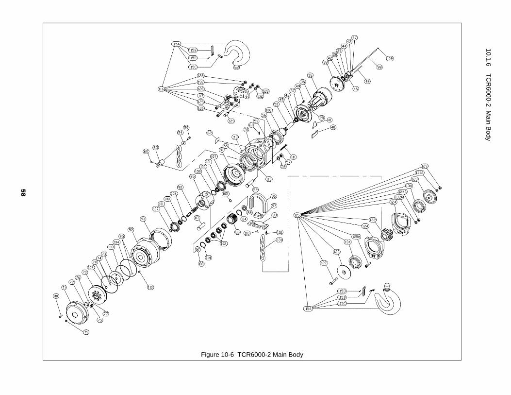
Figure 10-6 TCR6000-2 Main Body
10.1
.6 T
CR
60
00
-2 M
ain
Body
58
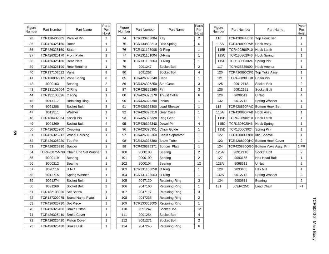
Figure Number
Part Number Part Name Parts Per
Hoist
28 TCR130406005 Parallel Pin 2
35 TCR426325150 Rotor 1
36 TCR426325160 Stator 1
37 TCR426325170 Front Plate 1
38 TCR426325180 Rear Plate 1
39 TCR426325190 Rear Retainer 1
40 TCR137102022 Vane 8
41 TCR130802212 Vane Spring 8
42 9000103 Bearing 2
43 TCR131103004 O-Ring 1
44 TCR131103026 O Ring 1
45 9047117 Retaining Ring 1
46 9091288 Socket Bolt 3
47 9012511 Washer 1
48 TCR130402054 Knock Pin 1
49 9091269 Socket Bolt 4
50 TCR426325200 Coupling 1
51 TCR426325212 Wheel Housing 1
52 TCR426325220 Top Pin 1
53 TCR426325230 Spacer 1
54 TCR420875MN0 Chain End Set Washer 1
55 9000119 Bearing 1
56 9000212 Bearing 1
57 9098516 U Nut 1
58 9012715 Spring Washer 1
59 9091274 Socket Bolt 1
60 9091269 Socket Bolt 2
61 TCR132108020 Set Screw 1
62 TCR137309075 Brand Name Plate 1
63 TCR426325730 Set Piece 1
70 TCR426325400 Brake Piston 1
71 TCR426325410 Brake Cover 1
72 TCR426325420 Piston Cover 1
73 TCR426325430 Brake Disk 1
Figure Number
Part Number Part Name Parts Per
Hoist
74 TCR130408084 Key 2
75 TCR130802213 Disc Spring 6
76 TCR131103008 O-Ring 1
77 TCR131101004 O-Ring 1
78 TCR131103063 O Ring 1
79 9091247 Socket Bolt 2
80 9091252 Socket Bolt 4
85 TCR426325240 Cage 1
86 TCR426325250 Star Gear 3
87 TCR426325260 Pin 3
88 TCR426325270 Thrust Collar 6
90 TCR426325290 Pinion 1
91 TCR426325300 Load Sheave 1
92 TCR426325310 Gear Case 1
93 TCR426325320 Ring Gear 1
95 TCR426325340 Dowel Pin 4
96 TCR426325351 Chain Guide 1
97 TCR426325360 Chain Separator 1
98 TCR426325380 Brake Tube 1
99 TCR426325371 Bottom Plate 1
100 9000103 Bearing 2
101 9000109 Bearing 2
102 9000104 Bearing 12
103 TCR131103058 O Ring 1
104 TCR131103063 O Ring 1
105 9047120 Retaining Ring 3
106 9047160 Retaining Ring 1
107 9047117 Retaining Ring 3
108 9047235 Retaining Ring 2
109 TCR130303005 Retaining Ring 1
110 9091247 Socket Bolt 12
111 9091284 Socket Bolt 4
112 9091271 Socket Bolt 2
114 9047245 Retaining Ring 6
Figure Number
Part Number Part Name Parts Per
Hoist
116 TCR4200HH006 Top Hook Set 1
115A TCR420890PAB Hook Assy. 1
115B TCR420890P10 Hook Latch 1
115C TCR130802046 Hook Spring 1
115D TCR130603024 Spring Pin 1
117 TCR426335690 Hook Anchor 1
120 TCR420890QF0 Top Yoke Assy. 1
121 TCR420890JG0 Chain Pin 1
125 90912118 Socket Bolt 2
126 90912121 Socket Bolt 1
128 9098511 U Nut 4
132 9012713 Spring Washer 4
115 TCR420890PAC Bottom Hook Set 1
115A TCR420890PAB Hook Assy. 1
115B TCR420890P10 Hook Latch 1
115C TCR130802046 Hook Spring 1
115D TCR130603024 Spring Pin 1
122 TCR420890RB0 Idle Sheave 1
123 TCR420890QH0 Bottom Hook Cover 2
124 TCR420890QG0 Bottom Yoke Assy. Pr. 1 PR
125A 90912118 Socket Bolt 2
127 9093155 Hex Head Bolt 1
128A 9098511 U Nut 2
129 9093433 Hex Nut 1
132A 9012713 Spring Washer 3
134 9000611 Bearing 2
131 LCER025C Load Chain FT
TC
R600
0-2
Main
Body
59
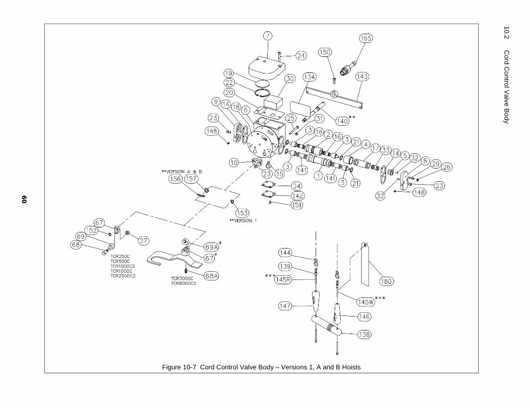
Figure 10-7 Cord Control Valve Body – Versions 1, A and B Hoists
10.2
C
ord
Co
ntro
l Valv
e B
ody
60
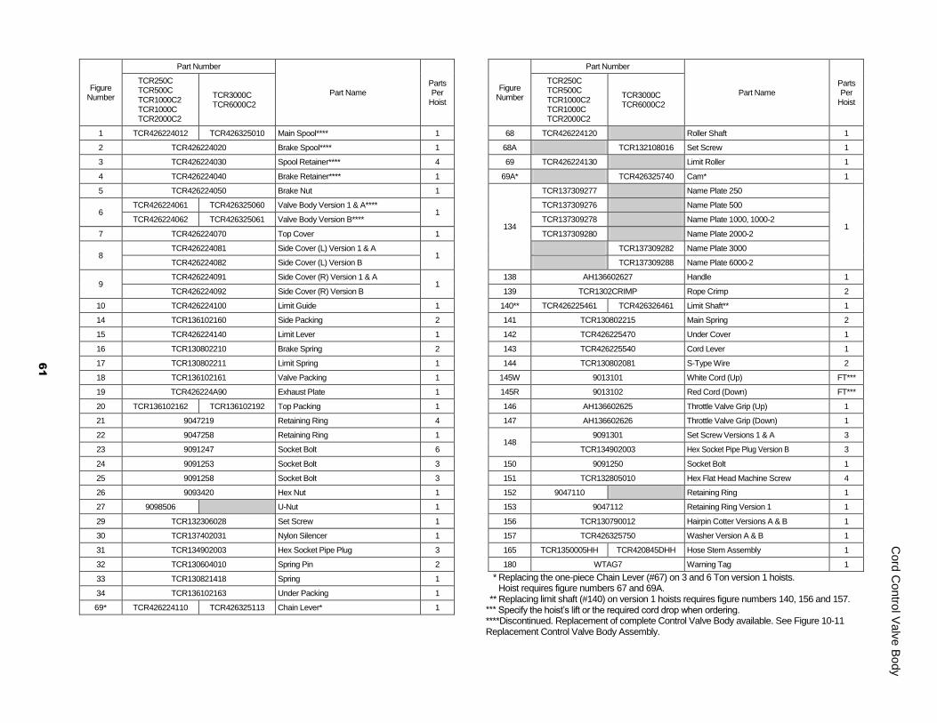
Figure Number
Part Number
Part Name Parts Per
Hoist
TCR250C TCR500C TCR1000C2 TCR1000C TCR2000C2
TCR3000C TCR6000C2
1 TCR426224012 TCR426325010 Main Spool**** 1
2 TCR426224020 Brake Spool**** 1
3 TCR426224030 Spool Retainer**** 4
4 TCR426224040 Brake Retainer**** 1
5 TCR426224050 Brake Nut 1
6 TCR426224061 TCR426325060 Valve Body Version 1 & A****
1 TCR426224062 TCR426325061 Valve Body Version B****
7 TCR426224070 Top Cover 1
8 TCR426224081 Side Cover (L) Version 1 & A
1 TCR426224082 Side Cover (L) Version B
9 TCR426224091 Side Cover (R) Version 1 & A
1 TCR426224092 Side Cover (R) Version B
10 TCR426224100 Limit Guide 1
14 TCR136102160 Side Packing 2
15 TCR426224140 Limit Lever 1
16 TCR130802210 Brake Spring 2
17 TCR130802211 Limit Spring 1
18 TCR136102161 Valve Packing 1
19 TCR426224A90 Exhaust Plate 1
20 TCR136102162 TCR136102192 Top Packing 1
21 9047219 Retaining Ring 4
22 9047258 Retaining Ring 1
23 9091247 Socket Bolt 6
24 9091253 Socket Bolt 3
25 9091258 Socket Bolt 3
26 9093420 Hex Nut 1
27 9098506 U-Nut 1
29 TCR132306028 Set Screw 1
30 TCR137402031 Nylon Silencer 1
31 TCR134902003 Hex Socket Pipe Plug 3
32 TCR130604010 Spring Pin 2
33 TCR130821418 Spring 1
34 TCR136102163 Under Packing 1
69* TCR426224110 TCR426325113 Chain Lever* 1
Figure Number
Part Number
Part Name Parts Per
Hoist
TCR250C TCR500C TCR1000C2 TCR1000C TCR2000C2
TCR3000C TCR6000C2
68 TCR426224120 Roller Shaft 1
68A TCR132108016 Set Screw 1
69 TCR426224130 Limit Roller 1
69A* TCR426325740 Cam* 1
134
TCR137309277 Name Plate 250
1
TCR137309276 Name Plate 500
TCR137309278 Name Plate 1000, 1000-2
TCR137309280 Name Plate 2000-2
TCR137309282 Name Plate 3000
TCR137309288 Name Plate 6000-2
138 AH136602627 Handle 1
139 TCR1302CRIMP Rope Crimp 2
140** TCR426225461 TCR426326461 Limit Shaft** 1
141 TCR130802215 Main Spring 2
142 TCR426225470 Under Cover 1
143 TCR426225540 Cord Lever 1
144 TCR130802081 S-Type Wire 2
145W 9013101 White Cord (Up) FT***
145R 9013102 Red Cord (Down) FT***
146 AH136602625 Throttle Valve Grip (Up) 1
147 AH136602626 Throttle Valve Grip (Down) 1
148 9091301 Set Screw Versions 1 & A 3
TCR134902003 Hex Socket Pipe Plug Version B 3
150 9091250 Socket Bolt 1
151 TCR132805010 Hex Flat Head Machine Screw 4
152 9047110 Retaining Ring 1
153 9047112 Retaining Ring Version 1 1
156 TCR130790012 Hairpin Cotter Versions A & B 1
157 TCR426325750 Washer Version A & B 1
165 TCR1350005HH TCR420845DHH Hose Stem Assembly 1
180 WTAG7 Warning Tag 1
* Replacing the one-piece Chain Lever (#67) on 3 and 6 Ton version 1 hoists. Hoist requires figure numbers 67 and 69A. ** Replacing limit shaft (#140) on version 1 hoists requires figure numbers 140, 156 and 157. *** Specify the hoist’s lift or the required cord drop when ordering. ****Discontinued. Replacement of complete Control Valve Body available. See Figure 10-11 Replacement Control Valve Body Assembly.
Cord
Co
ntro
l Valv
e B
ody
61
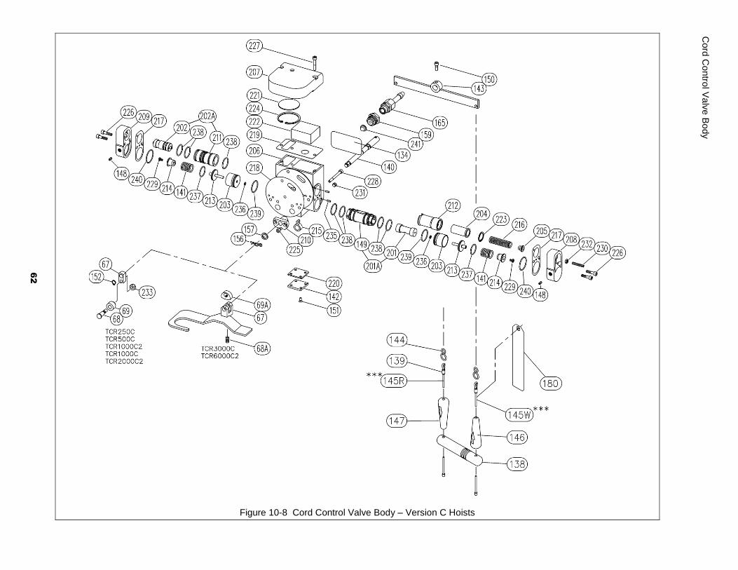
Figure 10-8 Cord Control Valve Body – Version C Hoists
Cord
Co
ntro
l Valv
e B
ody
62
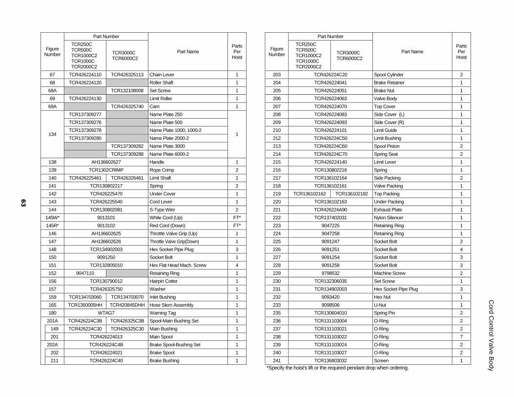
Figure Number
Part Number
Part Name Parts Per
Hoist
TCR250C TCR500C TCR1000C2 TCR1000C TCR2000C2
TCR3000C TCR6000C2
67 TCR426224110 TCR426325113 Chain Lever 1
68 TCR426224120 Roller Shaft 1
68A TCR132108008 Set Screw 1
69 TCR426224130 Limit Roller 1
69A TCR426325740 Cam 1
134
TCR137309277 Name Plate 250
1
TCR137309276 Name Plate 500
TCR137309278 Name Plate 1000, 1000-2
TCR137309280 Name Plate 2000-2
TCR137309282 Name Plate 3000
TCR137309288 Name Plate 6000-2
138 AH136602627 Handle 1
139 TCR1302CRIMP Rope Crimp 2
140 TCR426225461 TCR426326461 Limit Shaft 1
141 TCR130802217 Spring 2
142 TCR426225470 Under Cover 1
143 TCR426225540 Cord Lever 1
144 TCR130802081 S-Type Wire 2
145W* 9013101 White Cord (Up) FT*
145R* 9013102 Red Cord (Down) FT*
146 AH136602625 Throttle Valve Grip (Up) 1
147 AH136602626 Throttle Valve Grip(Down) 1
148 TCR134902003 Hex Socket Pipe Plug 3
150 9091250 Socket Bolt 1
151 TCR132805010 Hex Flat Head Mach. Screw 4
152 9047110 Retaining Ring 1
156 TCR130790012 Hairpin Cotter 1
157 TCR426325750 Washer 1
159 TCR134703060 TCR134703070 Inlet Bushing 1
165 TCR1350005HH TCR420845DHH Hose Stem Assembly 1
180 WTAG7 Warning Tag 1
201A TCR426224C3B TCR426325C3B Spool-Main Bushing Set 1
149 TCR426224C30 TCR426325C30 Main Bushing 1
201 TCR426224013 Main Spool 1
202A TCR426224C4B Brake Spool-Bushing Set 1
202 TCR426224021 Brake Spool 1
211 TCR426224C40 Brake Bushing 1
Figure Number
Part Number
Part Name Parts Per
Hoist
TCR250C TCR500C TCR1000C2 TCR1000C TCR2000C2
TCR3000C TCR6000C2
203 TCR426224C20 Spool Cylinder 2
204 TCR426224041 Brake Retainer 1
205 TCR426224051 Brake Nut 1
206 TCR426224063 Valve Body 1
207 TCR426224070 Top Cover 1
208 TCR426224083 Side Cover (L) 1
209 TCR426224093 Side Cover (R) 1
210 TCR426224101 Limit Guide 1
212 TCR426224C50 Limit Bushing 1
213 TCR426224C60 Spool Piston 2
214 TCR426224C70 Spring Seat 2
215 TCR426224140 Limit Lever 1
216 TCR130802216 Spring 1
217 TCR136102164 Side Packing 2
218 TCR136102161 Valve Packing 1
219 TCR136102162 TCR136102192 Top Packing 1
220 TCR136102163 Under Packing 1
221 TCR426224A90 Exhaust Plate 1
222 TCR137402031 Nylon Silencer 1
223 9047225 Retaining Ring 1
224 9047258 Retaining Ring 1
225 9091247 Socket Bolt 2
226 9091251 Socket Bolt 4
227 9091254 Socket Bolt 3
228 9091258 Socket Bolt 3
229 9798532 Machine Screw 2
230 TCR132306035 Set Screw 1
231 TCR134902003 Hex Socket Pipe Plug 3
232 9093420 Hex Nut 1
233 9098506 U-Nut 1
235 TCR130604010 Spring Pin 2
236 TCR131103004 O-Ring 2
237 TCR131103021 O-Ring 2
238 TCR131103022 O-Ring 7
239 TCR131103024 O-Ring 2
240 TCR131103027 O-Ring 2
241 TCR136803032 Screen 1
*Specify the hoist's lift or the required pendant drop when ordering.
61
Cord
Co
ntro
l Valv
e B
ody
Cord
Co
ntro
l Valv
e B
ody
63

Figure 10-9 Pendant Control Valve Body – Versions 1, A and B Hoists
10.3
P
en
dant C
ontro
l Va
lve B
od
y
64
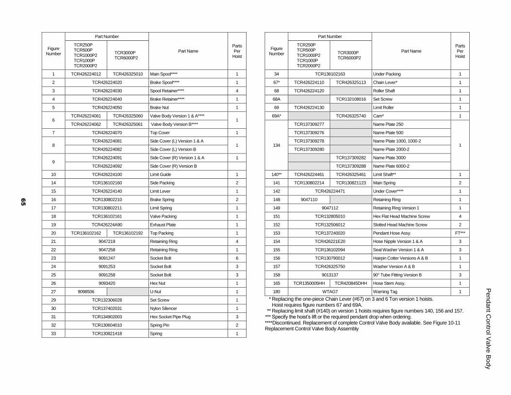
Figure Number
Part Number
Part Name Parts Per
Hoist
TCR250P TCR500P TCR1000P2 TCR1000P TCR2000P2
TCR3000P TCR6000P2
1 TCR426224012 TCR426325010 Main Spool**** 1
2 TCR426224020 Brake Spool**** 1
3 TCR426224030 Spool Retainer**** 4
4 TCR426224040 Brake Retainer**** 1
5 TCR426224050 Brake Nut 1
6 TCR426224061 TCR426325060 Valve Body Version 1 & A****
1 TCR426224062 TCR426325061 Valve Body Version B****
7 TCR426224070 Top Cover 1
8 TCR426224081 Side Cover (L) Version 1 & A
1 TCR426224082 Side Cover (L) Version B
9 TCR426224091 Side Cover (R) Version 1 & A 1
TCR426224092 Side Cover (R) Version B
10 TCR426224100 Limit Guide 1
14 TCR136102160 Side Packing 2
15 TCR426224140 Limit Lever 1
16 TCR130802210 Brake Spring 2
17 TCR130802211 Limit Spring 1
18 TCR136102161 Valve Packing 1
19 TCR426224A90 Exhaust Plate 1
20 TCR136102162 TCR136102192 Top Packing 1
21 9047219 Retaining Ring 4
22 9047258 Retaining Ring 1
23 9091247 Socket Bolt 6
24 9091253 Socket Bolt 3
25 9091258 Socket Bolt 3
26 9093420 Hex Nut 1
27 9098506 U-Nut 1
29 TCR132306028 Set Screw 1
30 TCR137402031 Nylon Silencer 1
31 TCR134902003 Hex Socket Pipe Plug 3
32 TCR130604010 Spring Pin 2
33 TCR130821418 Spring 1
Figure Number
Part Number
Part Name Parts Per
Hoist
TCR250P TCR500P TCR1000P2 TCR1000P TCR2000P2
TCR3000P TCR6000P2
34 TCR136102163 Under Packing 1
67* TCR426224110 TCR426325113 Chain Lever* 1
68 TCR426224120 Roller Shaft 1
68A TCR132108016 Set Screw 1
69 TCR426224130 Limit Roller 1
69A* TCR426325740 Cam* 1
134
TCR137309277 Name Plate 250
1
TCR137309276 Name Plate 500
TCR137309278 Name Plate 1000, 1000-2
TCR137309280 Name Plate 2000-2
TCR137309282 Name Plate 3000
TCR137309288 Name Plate 6000-2
140** TCR426224461 TCR426325461 Limit Shaft** 1
141 TCR130802214 TCR130821123 Main Spring 2
142 TCR426224471 Under Cover**** 1
148 9047110 Retaining Ring 1
149 9047112 Retaining Ring Version 1 1
151 TCR132805010 Hex Flat Head Machine Screw 4
152 TCR132506012 Slotted Head Machine Screw 2
153 TCR137240020 Pendant Hose Assy. FT***
154 TCR426221E20 Hose Nipple Version 1 & A 3
155 TCR136102094 Seal Washer Version 1 & A 3
156 TCR130790012 Hairpin Cotter Versions A & B 1
157 TCR426325750 Washer Version A & B 1
158 9013137 90° Tube Fitting Version B 3
165 TCR1350005HH TCR420845DHH Hose Stem Assy. 1
180 WTAG7 Warning Tag 1
* Replacing the one-piece Chain Lever (#67) on 3 and 6 Ton version 1 hoists. Hoist requires figure numbers 67 and 69A. ** Replacing limit shaft (#140) on version 1 hoists requires figure numbers 140, 156 and 157. *** Specify the hoist’s lift or the required pendant drop when ordering. ****Discontinued. Replacement of complete Control Valve Body available. See Figure 10-11 Replacement Control Valve Body Assembly
65
Pen
dant C
ontro
l Va
lve B
od
y
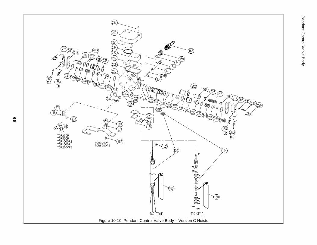
Figure 10-10 Pendant Control Valve Body – Version C Hoists
Pen
dant C
ontro
l Va
lve B
od
y
66
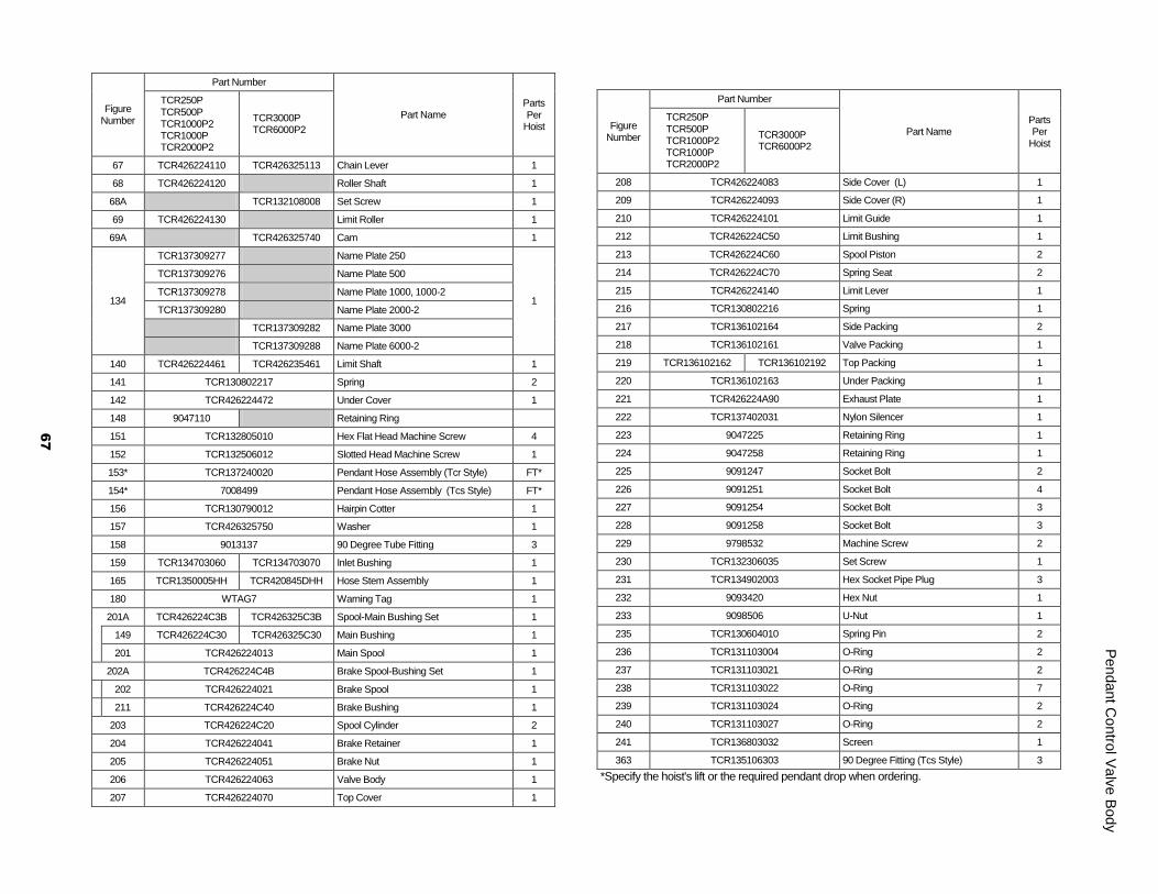
Figure Number
Part Number
Part Name Parts Per
Hoist
TCR250P TCR500P TCR1000P2 TCR1000P TCR2000P2
TCR3000P TCR6000P2
67 TCR426224110 TCR426325113 Chain Lever 1
68 TCR426224120 Roller Shaft 1
68A TCR132108008 Set Screw 1
69 TCR426224130 Limit Roller 1
69A TCR426325740 Cam 1
134
TCR137309277 Name Plate 250
1
TCR137309276 Name Plate 500
TCR137309278 Name Plate 1000, 1000-2
TCR137309280 Name Plate 2000-2
TCR137309282 Name Plate 3000
TCR137309288 Name Plate 6000-2
140 TCR426224461 TCR426235461 Limit Shaft 1
141 TCR130802217 Spring 2
142 TCR426224472 Under Cover 1
148 9047110 Retaining Ring
151 TCR132805010 Hex Flat Head Machine Screw 4
152 TCR132506012 Slotted Head Machine Screw 1
153* TCR137240020 Pendant Hose Assembly (Tcr Style) FT*
154* 7008499 Pendant Hose Assembly (Tcs Style) FT*
156 TCR130790012 Hairpin Cotter 1
157 TCR426325750 Washer 1
158 9013137 90 Degree Tube Fitting 3
159 TCR134703060 TCR134703070 Inlet Bushing 1
165 TCR1350005HH TCR420845DHH Hose Stem Assembly 1
180 WTAG7 Warning Tag 1
201A TCR426224C3B TCR426325C3B Spool-Main Bushing Set 1
149 TCR426224C30 TCR426325C30 Main Bushing 1
201 TCR426224013 Main Spool 1
202A TCR426224C4B Brake Spool-Bushing Set 1
202 TCR426224021 Brake Spool 1
211 TCR426224C40 Brake Bushing 1
203 TCR426224C20 Spool Cylinder 2
204 TCR426224041 Brake Retainer 1
205 TCR426224051 Brake Nut 1
206 TCR426224063 Valve Body 1
207 TCR426224070 Top Cover 1
Figure Number
Part Number
Part Name Parts Per
Hoist
TCR250P TCR500P TCR1000P2 TCR1000P TCR2000P2
TCR3000P TCR6000P2
208 TCR426224083 Side Cover (L) 1
209 TCR426224093 Side Cover (R) 1
210 TCR426224101 Limit Guide 1
212 TCR426224C50 Limit Bushing 1
213 TCR426224C60 Spool Piston 2
214 TCR426224C70 Spring Seat 2
215 TCR426224140 Limit Lever 1
216 TCR130802216 Spring 1
217 TCR136102164 Side Packing 2
218 TCR136102161 Valve Packing 1
219 TCR136102162 TCR136102192 Top Packing 1
220 TCR136102163 Under Packing 1
221 TCR426224A90 Exhaust Plate 1
222 TCR137402031 Nylon Silencer 1
223 9047225 Retaining Ring 1
224 9047258 Retaining Ring 1
225 9091247 Socket Bolt 2
226 9091251 Socket Bolt 4
227 9091254 Socket Bolt 3
228 9091258 Socket Bolt 3
229 9798532 Machine Screw 2
230 TCR132306035 Set Screw 1
231 TCR134902003 Hex Socket Pipe Plug 3
232 9093420 Hex Nut 1
233 9098506 U-Nut 1
235 TCR130604010 Spring Pin 2
236 TCR131103004 O-Ring 2
237 TCR131103021 O-Ring 2
238 TCR131103022 O-Ring 7
239 TCR131103024 O-Ring 2
240 TCR131103027 O-Ring 2
241 TCR136803032 Screen 1
363 TCR135106303 90 Degree Fitting (Tcs Style) 3
*Specify the hoist's lift or the required pendant drop when ordering.
67
10.4
– R
epla
cem
ent V
alv
e B
ody
67
Pen
dant C
ontro
l Va
lve B
od
y
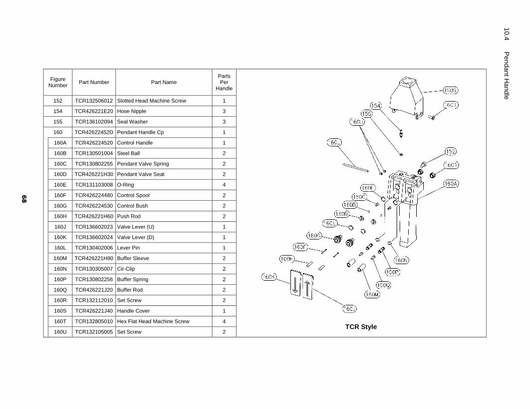
Figure Number
Part Number Part Name Parts Per
Handle
TCR Style
152 TCR132506012 Slotted Head Machine Screw 1
154 TCR426221E20 Hose Nipple 3
155 TCR136102094 Seal Washer 3
160 TCR42622452D Pendant Handle Cp 1
160A TCR426224520 Control Handle 1
160B TCR130501004 Steel Ball 2
160C TCR130802255 Pendant Valve Spring 2
160D TCR426221H30 Pendant Valve Seat 2
160E TCR131103008 O-Ring 4
160F TCR426224480 Control Spool 2
160G TCR426224530 Control Bush 2
160H TCR426221H60 Push Rod 2
160J TCR136602023 Valve Lever (U) 1
160K TCR136602024 Valve Lever (D) 1
160L TCR130402006 Lever Pin 1
160M TCR426221H90 Buffer Sleeve 2
160N TCR130305007 Cir-Clip 2
160P TCR130802256 Buffer Spring 2
160Q TCR426221J20 Buffer Rod 2
160R TCR132112010 Set Screw 2
160S TCR426221J40 Handle Cover 1
160T TCR132805010 Hex Flat Head Machine Screw 4
160U TCR132105005 Set Screw 2
Pen
dant H
andle
68
10.4
P
en
dant H
andle

Figure Number
Part Number Part Name Parts Per
Handle
TCS Style
152 TCR132506012 Slotted Flat Head Machine Screw 1
330 TCS135106302 Hose Joint 3
332 TCS137501013 Hose Band 3
335 TCR130802081 S-Type Wire 1
338 TCS137502036 Cable Tie - White 2
339 TCS137502037 Cable Tie - Black 2
360 9013156 Tcs Hose AR
361 9013120 Strain Relief Cable AR
364 9013155 Hose Clamp 6
365 TCR135111022 Connector For Under Cover 1
299 TCS420226VRD Pendant Handle Cp 1
300 TCR420218VB0 Throttle Valve 2
301 TCS420226VR0 Valve Body 1
302 TCR420218VF0 Bushing 2
303 TCS130402071 Lever Pin 1
304 TCS420218VH0 Lever 2
305 TCS130802220 Spring 2
306 TCS132106006 Hex.Socket Set Screw 1
307 TCS131109001 O-Ring 2
308 TCR131103008 O-Ring 2
309 TCS131103009 O-Ring 2
69
Pen
dant H
andle
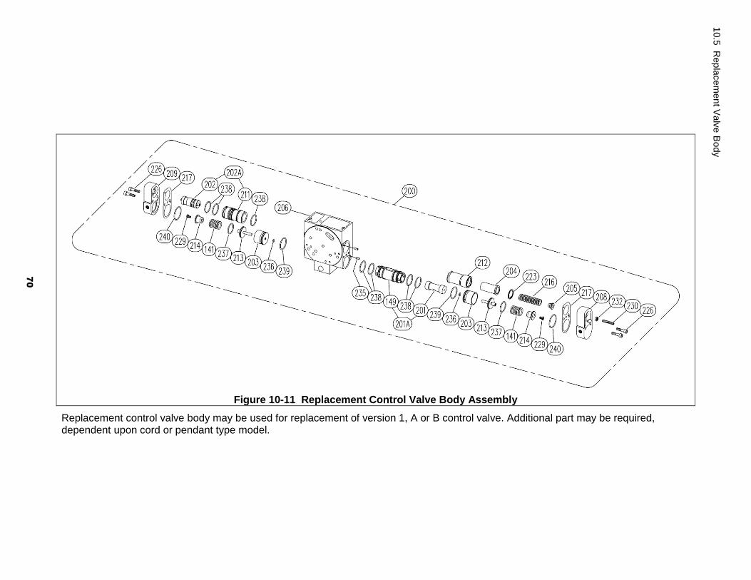
Figure 10-11 Replacement Control Valve Body Assembly
Replacement control valve body may be used for replacement of version 1, A or B control valve. Additional part may be required, dependent upon cord or pendant type model.
10.5
Rep
lace
men
t Valv
e B
ody
70

Figure Number
Part Number
Part Name Parts Per
Hoist
TCR250P TCR500P TCR1000P2 TCR1000P TCR2000P2
TCR3000P TCR6000P2
200 TCR426274D7D TCR426342D7D Control Valve Assembly 1
141 TCR130802217 Spring 2
201A TCR426224C3B TCR426325C3B Spool-Main Bushing Set 1
149 TCR426224C30 TCR426325C30 Main Bushing 1
201 TCR426224013 Main Spool 1
202A TCR426224C4B Brake Spool-Bushing Set 1
202 TCR426224021 Brake Spool 1
211 TCR426224C40 Brake Bushing 1
203 TCR426224C20 Spool Cylinder 2
204 TCR426224041 Brake Retainer 1
205 TCR426224051 Brake Nut 1
206 TCR426224063 Valve Body 1
208 TCR426224083 Side Cover (L) 1
209 TCR426224093 Side Cover (R) 1
212 TCR426224C50 Limit Bushing 1
213 TCR426224C60 Spool Piston 2
214 TCR426224C70 Spring Seat 2
216 TCR130802216 Spring 1
217 TCR136102164 Side Packing 2
223 9047225 Retaining Ring 1
226 9091251 Socket Bolt 4
229 9798532 Machine Screw 2
230 TCR132306035 Set Screw 1
232 9093420 Hex Nut 1
235 TCR130604010 Spring Pin 2
236 TCR131103004 O-Ring 2
237 TCR131103021 O-Ring 2
238 TCR131103022 O-Ring 7
239 TCR131103024 O-Ring 2
240 TCR131103027 O-Ring 2
71
Repla
cem
ent V
alv
e B
ody
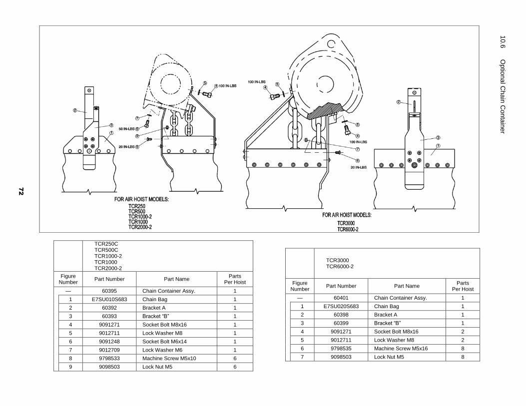
TCR250C
TCR500C TCR1000-2 TCR1000 TCR2000-2
Figure Number
Part Number Part Name Parts
Per Hoist
— 60395 Chain Container Assy. 1
1 E7SU010S683 Chain Bag 1
2 60392 Bracket A 1
3 60393 Bracket “B” 1
4 9091271 Socket Bolt M8x16 1
5 9012711 Lock Washer M8 1
6 9091248 Socket Bolt M6x14 1
7 9012709 Lock Washer M6 1
8 9798533 Machine Screw M5x10 6
9 9098503 Lock Nut M5 6
TCR3000
TCR6000-2
Figure Number
Part Number Part Name Parts
Per Hoist
— 60401 Chain Container Assy. 1
1 E7SU020S683 Chain Bag 1
2 60398 Bracket A 1
3 60399 Bracket “B” 1
4 9091271 Socket Bolt M8x16 2
5 9012711 Lock Washer M8 2
6 9798535 Machine Screw M5x16 8
7 9098503 Lock Nut M5 8
10.6
O
ptio
nal C
ha
in C
on
tain
er
72

73
NOTES

74
NOTES

75
NOTES
Harrington Hoists, Inc. 401 West End Avenue Manheim, PA 17545
www.harringtonhoists.com Toll Free: 800-233-3010 Phone: 717-665-2000
Fax: 717-665-2861
TCROM-ENG