vejp .pojuor
TRANSCRIPT

making science easierADINSTRUMENTS
MA3300 AudioMonitor
Owner’s Guide

Th is document was, as far as possible, accurate at the time of release. However, changes may have been made to the soft ware and hardware it describes since then. ADInstruments Pty Ltd. reserves the right to alter specifi cation as required. Late-breaking information may be supplied separately.
Trademarks of ADInstruments
PowerLab®, LabChart®, LabTutor®, LabAuthor® and MacLab® are registered trademarks of ADInstruments Pty Ltd. The names of specific recording units, such as PowerLab 8/35, are trademarks of ADInstruments Pty Ltd. LabTutor Server, Chart and Scope (application programs) and LabTutor Online are trademarks of ADInstruments Pty Ltd.
Other Trademarks
Apple, Mac and Macintosh are registered trademarks of Apple Computer, Inc.
Windows, Windows 7 and Windows Vista are either registered trademarks or trademarks of Microsoft Corporation.
All other trademarks are the property of their respective owners.
making science easierADINSTRUMENTS
Product: MA3300 Audio Monitor
Copyright © April 2014 ADInstruments Pty Ltd.Unit 13, 22 Lexington Drive, Bella Vista, NSW 2153, Australia
All rights reserved. No part of this document may be reproduced by any means without the prior writtenpermission of ADInstruments Pty Ltd.
Web: www.adinstruments.comTechnical Support: [email protected] Documentation: [email protected]
ADInstruments Pty Ltd. ISO 9001:2008 Certified Quality Management System
Reg. No. 1053

1A-M Systems, Inc. 131 Business Park Loop, P.O. Box 850 Carlsborg, Wa 98324Telophone: 800-426-1306 * 360-683-8300 * FAX: 360-683-3525E-mail: [email protected] * Website: http://www.a-msystems.com
General Description
Instrument FeaturesThe Model 3300 Audio Monitor is a high quality audio amplifier designed to transformelectrophysiological signals into sounds. This amplifier features a built-in 6-band audioequalizer that enables the user to tailor the audio performance to their personalsatisfaction, a high-fidelity quality speaker, a dedicated notch filter designed to minimizenoise interference generated by power lines, a headphone jack, and an BNC line out jackthat enables the the Model 3300 to be used as another signal amplifier prior tosubsequent processing by other instruments.
The instrument can be placed on a lab bench with its built-in metal stand, or it can bemounted in any industry standard equipment rack (with included rack-mounting hardware).In addition, the instrument is shipped with it’s own desktop power supply.
It can be used in a number of research or teaching applications requiring the audioreproduction of electrophysiological signals, such as such as nerve, muscle (EMG), EEG,EKG, and ERG recordings.
The instrument is not intended for clinical measurements using humans.
Two input signals can be passed to the Model 3300. A toggle switch selects which of thetwo signals will be amplified and processed by the 6-band equalizer. The Equalizer is atunable filter that can increase or decrease the gain of particular frequency ranges,resulting in a pleasing sound quality produced at the speaker. The use of a set ofheadphones (by utilizing the mini-headphone jack) will disable the internal audio speaker.The volume control acts as a variable gain amplifier, and adjusts the volume of thespeaker output. The processed signal can be passed to an oscilloscope or otherinstruments via the Signal Out BNC jack.

2A-M Systems, Inc. 131 Business Park Loop, P.O. Box 850 Carlsborg, Wa 98324Telophone: 800-426-1306 * 360-683-8300 * FAX: 360-683-3525E-mail: [email protected] * Website: http://www.a-msystems.com
Controls and ConnectorsINPUT: Signals to be processed are connected to the AudioMonitor at these two BNC jacks (Ch. 1 and Ch. 2).
CHANNEL: This toggle switch determines which of the twoinput signals will be processed.
GAIN: This three position switch controls the level of signalgain. The switch allows the user to select from X1, X10, orX100 gain.
NOTCH FILTER: In the ON position, this filter will attenuateline noise (Either 50 or 60 Hz, depending on the country ofuse).
GRAPHIC EQUALIZER: These 6 slide potentiometers adjustthe gain of a narrow range of frequencies. Each slidepotentiometer can boost/increase (+) or attenuate/decrease(-) the gain around the center frequency indicated (160Hz,400Hz, 800Hz, 1.6kHz, 3.2kHz, and 8.0kHz) by 12dB.
LINE OUT: This BNC connector provides the output signalfrom the amplifier channel. The toggle switch determines ifthis signal is FIXED in gain relative to the input signal (at thelevel determined by the GAIN toggle switch or includes theVARIABLE amplification provided by the GRAPHICEQUALIZER AND VOLUME control.
VOLUME: This potentiometer adjusts the output volume ofthe speaker, and the variable amplification to the processedsignal. Warning: It is recommended to turn this knob tothe off position before attaching an input signal to theAudio Monitor, in order to prevent damage to the speaker,and any nearby eardrums.
HEADPHONES JACK: Insertion of a mini-headphones pluginto this jack will disable the internal speaker, and power theuser supplied headphones.

3A-M Systems, Inc. 131 Business Park Loop, P.O. Box 850 Carlsborg, Wa 98324Telophone: 800-426-1306 * 360-683-8300 * FAX: 360-683-3525E-mail: [email protected] * Website: http://www.a-msystems.com
Operating Instructions
Typical Set-Up ProcedureTurn the VOLUME control to the off position prior to connecting an input signal to eitherof the two input channels in order to prevent damage to the internal speaker or anynearby eardrums.
Using the Channel Switch, select the desired input signal channel to be amplified.Determine the gain setting. Start with the lowest GAIN setting possible, and slowlyincrease the VOLUME control until a desired audio level is obtained. If you reach themaximum setting on the VOLUME control and the signal is still too quiet, return theVOLUME control to the off position and increase the GAIN to the next greater level.
If you would like to minimize power line generated noise, switch the NOTCH filter to On.
Adjust the GRAPHIC EQUALIZER slide knobs to increase or decrease the gain ofcertain frequency ranges in order to produce a more pleasing audio sound.

4A-M Systems, Inc. 131 Business Park Loop, P.O. Box 850 Carlsborg, Wa 98324Telophone: 800-426-1306 * 360-683-8300 * FAX: 360-683-3525E-mail: [email protected] * Website: http://www.a-msystems.com
Theory of Operation
One of two inputs may be selected using the CHANNEL switch. The selected input isthen amplified according to the setting of the GAIN switch. After amplification, the signalcan be filtered at the frequency of the power line by use of the NOTCH filter.
Particular narrow ranges of frequencies of the processed signal can then be boosted orattenuated using the GRAPHIC EQUALIZER. Maximum boost or attenuation is +/-12dB, centered on the frequency indicated under each slide knob.
The output of the graphic equalizer feeds directly into the VOLUME control and LINEOUTput. Setting the LINE OUT Switch to Variable will produce the processed signal withthe additional variable gain provided by the VOLUME control at the BNC jack. Settingthe LINE OUT Switch to Fixed will provide the processed signal at the gain indicated bythe GAIN switch (taken prior to the GRAPHIC EQUALIZER) at the BNC output jack.
The signal is then amplified using a power amplifier circuit in order to provide enoughcurrent to drive either the internal speaker or an external user-supplied set of headphones.Inserting a mini-headphones plug into the headphones jack will disable the internalspeaker.
Figure 1. Main circuit block diagram
GAIN
NOTCH FILTER50/60Hz
OFF
ON
FIXEDLINEOUT
VARIABLE
POWER
INPUT
AMPLIFIER
AMPLIFIER
HEADPHONES
INTERNALLOUDSPEAKER
INPUT 1
INPUT 2
x1x10x100
GRAPHICEQUALIZER
HEADPHONEJACK
VOLUME
160Hz 400Hz 800Hz 1.6kHz 3.2kHz 8.0kHz

5A-M Systems, Inc. 131 Business Park Loop, P.O. Box 850 Carlsborg, Wa 98324Telophone: 800-426-1306 * 360-683-8300 * FAX: 360-683-3525E-mail: [email protected] * Website: http://www.a-msystems.com
Specifications
AmplifierGain: 1V/V, 10V/V, 100V/V (+40dB)
Sensitivity: 0.01V p-p
Input resistance: 20MΩ
Maximum input before LINE OUT clips:GAIN: x1 10.0VGAIN: x10 1.0VGAIN: x100 0.1V
Maximum input before SPEAKER clips (with volume control fully clockwise):GAIN: x1 1.0VGAIN: x10 0.1VGAIN: x100 0.01V
Noise (At Fixed Line Out)470Ω source resistance (not shorted input)
22Hz-22kHz: 14µV p-p (57dB signal to noise)1kHz spot frequency: 3µV p-p (70dB signal to noise)
2,200pF source capacitance to emulate a crystal/ceramic transducer sourceWithout NOTCH Filter (22Hz-22kHz): 220µV p-p (33dB signal to noise)With NOTCH Filter (22Hz-22kHz): 28µV p-p (51dB signal to noise)1kHz spot frequency: 1µV p-p (80dB signal to noise)
Notch FilterGain: Unity (0dB)Notch Frequency: 60Hz (50Hz in specific countries)Notch Depth: -29dB
Graphic EqualizerGain: Unity (0dB)Boost/Cut Frequencies (Hz): 160, 400, 800, 1600, 3200, 8000Nominal Boost & Cut: +/- 10dB (within 1dB)
Power AmplifierPower output: 2.7W continuous (rms) sine wave into 4Ω
5.4W continuous (peak) sine wave into 4ΩDistortion (THD+N): <0.3%, 80Hz - 16kHz (at rated power)
6A-M Systems, Inc. 131 Business Park Loop, P.O. Box 850 Carlsborg, Wa 98324Telophone: 800-426-1306 * 360-683-8300 * FAX: 360-683-3525E-mail: [email protected] * Website: http://www.a-msystems.com
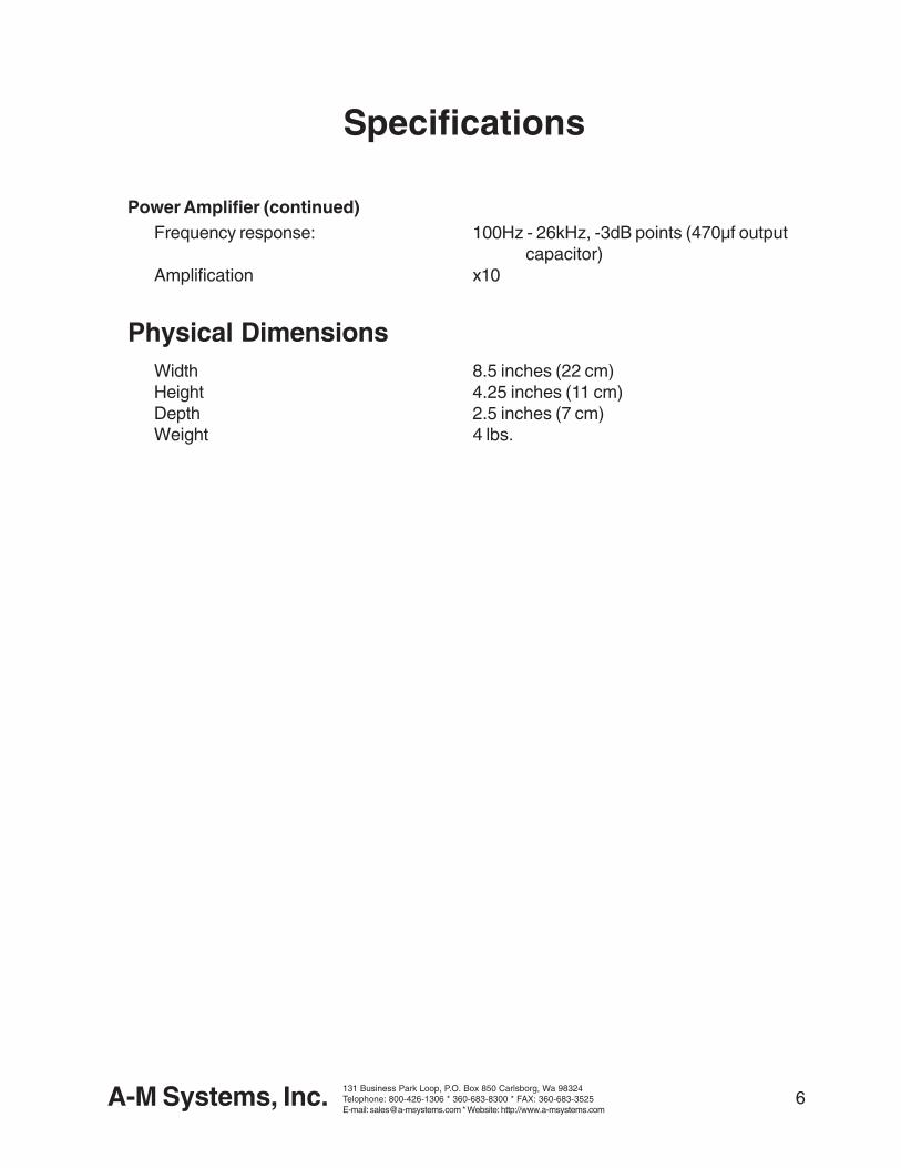
Specifications
Power Amplifier (continued)Frequency response: 100Hz - 26kHz, -3dB points (470µf output
capacitor)Amplification x10
Physical DimensionsWidth 8.5 inches (22 cm)Height 4.25 inches (11 cm)Depth 2.5 inches (7 cm)Weight 4 lbs.

7A-M Systems, Inc. 131 Business Park Loop, P.O. Box 850 Carlsborg, Wa 98324Telophone: 800-426-1306 * 360-683-8300 * FAX: 360-683-3525E-mail: [email protected] * Website: http://www.a-msystems.com
Warranty and Service
What does this warranty cover?A-M Systems, Inc. warrants to the Purchaser that the Instrument, excluding cables, Headstage Probesand any other accessories shipped with the Instrument, (hereafter the “hardware”) is free from defects inworkmanship or material under normal use and service for the period of one (1) year. This warrantycommences on the date of delivery of the hardware to the Purchaser.
What are the obligations of A-M Systems, Inc. under this warranty?During the warranty period, A-M Systems, Inc. agrees to repair or replace, at its sole option, withoutcharge to the Purchaser, any defective component part of the hardware. To obtain warranty service, thePurchaser must return the hardware to A-M Systems, Inc. or an authorized A-M Systems, Inc. distributorin an adequate shipping container. Any postage, shipping and insurance charges incurred in shipping thehardware to A-M Systems, Inc. must be prepaid by the Purchaser and all risk for the hardware shallremain with purchaser until such time as A-M Systems, Inc. takes receipt of the hardware. Upon receipt,A-M Systems, Inc. will promptly repair or replace the defective unit, and then return the hardware to thePurchaser, postage, shipping, and insurance prepaid. A-M Systems, Inc. may use reconditioned or likenew parts or units at its sole option, when repairing any hardware. Repaired products shall carry the sameamount of outstanding warranty as from original purchase, or ninety (90) days which ever is greater. Anyclaim under the warranty must include a dated proof of purchase of the hardware covered by thiswarranty. In any event, A-M Systems, Inc. liability for defective hardware is limited to repairing or replacingthe hardware.
What is not covered by this warranty?This warranty is contingent upon proper use and maintenance of the hardware by the Purchaser anddoes not cover batteries. Neglect, misuse whether intentional or otherwise, tampering with or altering thehardware, damage caused by accident, damage caused by unusual physical, electrical, chemical, orelectromechanical stress, damage caused by failure of electrical power, or damage caused duringtransportation are not covered by this warranty. Products may not be returned to A-M Systems, Inc.for service, whether under warranty or otherwise, which are contaminated by infectious agents,radioactive compounds or other materials constituting a health hazard to employees of A-MSystems, Inc.
What are the limits of liability for A-M Systems, Inc. under this warranty?A-M Systems, Inc. shall not be liable for loss of data, profits or savings, or any special, incidental,consequential, indirect or other similar damages arising from breach of contract, negligence, or otherlegal action even if the company or its agent has been advised of the possibility of such damages, or forany claim brought against you by another party. THIS EQUIPMENT IS NOT INTENDED FOR CLINICALMEASUREMENTS USING HUMAN SUBJECTS. A-M SYSTEMS, INC. DOES NOT ASSUMERESPONSIBILITY FOR INJURY OR DAMAGE DUE TO MISUSE OF THIS EQUIPMENT. Jurisdictionsvary with regard to the enforceability of provisions excluding or limiting liability for incidental orconsequential damages. Check the provision of your local jurisdiction to find out whether the aboveexclusion applies to you.
This warranty allocates risks of product failure between the Purchaser and A-M Systems, Inc. A-MSystems, Inc. hardware pricing reflects this allocation of risk and the limitations of liability contained in thiswarranty. The warranty set forth above is in lieu of all other express warranties, whether oral or written.The agents, employees, distributors, and dealers of A-M Systems, Inc. are not authorized to makemodifications to this warranty, or additional warranties binding on the company. Accordingly, additionalstatements such as dealer advertising or presentations, whether oral or written, do not constitutewarranties by A-M Systems, Inc. and should not be relied upon. This warranty gives you specific legalrights. You may also have other rights which vary from one jurisdiction to another.