· web view256-color vga programming in c. bitmaps & palette manipulation. contents in this...
TRANSCRIPT

256-Color VGA Programming in C
Bitmaps & Palette ManipulationContents in this section:
What is a bitmap? The BMP file format Drawing bitmaps Program: bitmap.c Palette manipulation Program: palette.c Vertical retrace
What is a bitmap?One of the most important things in creating a user-friendly interface is the use of bitmaps. Without bitmaps, there would be no icons, no fancy buttons, and mouse pointers would have to be made of lines.
The term bitmap is a throwback from when monitors could only display one other color besides black. For two-color data files that store an image, each bit in the data file represents one pixel; a 1 meant the pixel was on, a 0 meant the pixel was off (Figure 13). Therefore, a two-color image is a map of bits.
Figure 13. A black & white bitmap in memory and on the screen.
The BMP file formatThere are many file formats for storing bitmaps, such as RLE, JPEG, TIFF, TGA, PCX, BMP, PNG, PCD and GIF. The bitmaps studied in this section will be 256-color bitmaps, where eight bits represents one pixel.. One of the easiest 256-color bitmap file format is Windows' BMP. This file format can be stored uncompressed, so reading BMP files is fairly simple; most other graphics formats are compressed, and some, like GIF, are difficult to decompress. To learn about other graphics file formats, visit x2ftp.
There are a few different sub-types of the BMP file format. The one studied here is Windows' RGB-encoded BMP format. For 256-color bitmaps, it has a 54-byte header (Table III) followed by a 1024-byte palette table. After that is the actual bitmap, which starts at the lower-left hand corner.
Data DescriptionWORD Type; File type. Set to "BM".

DWORD Size; Size in BYTES of the file.DWORD Reserved; Reserved. Set to zero.DWORD Offset; Offset to the data.DWORD headerSize; Size of rest of header. Set to 40.DWORD Width; Width of bitmap in pixels.DWORD Height; Height of bitmap in pixels.WORD Planes; Number of Planes. Set to 1.WORD BitsPerPixel; Number of bits per pixel.DWORD Compression; Compression. Usually set to 0.DWORD SizeImage; Size in bytes of the bitmap.DWORD XPixelsPerMeter; Horizontal pixels per meter.DWORD YPixelsPerMeter; Vertical pixels per meter.DWORD ColorsUsed; Number of colors used.DWORD ColorsImportant; Number of "important" colors.
Table III. Windows' BMP file format header.
Drawing bitmapsOnce read, displaying the bitmap is relatively easy, and involves only a few memory copies to display memory. The following is the code to display a 32x64 image stored in an array bitmap:
for(y=0;y<64;y++) for(x=0;x<32;x++) VGA [x+y*320]=bitmap [x+y*32];
Something interesting to note about the BMP file format is that each scan line is padded to the nearest 4-byte boundry. So, if the image read has a width that is not divisible by four, say, 21 bytes, there would be 3 bytes of padding at the end of every scan line. The program bitmap.exe does not account for this; it assumes the bitmap's width is divisible by four.
There are many techniques to implement transparency. One way is to assign one of the 256 colors to be transparent in the program. When drawing the image, a byte with the transparency value is not written to video memory. The following implements this using zero as the transparency value:
for(y=0;y<64;y++) for(x=0;x<32;x++) { data=bitmap [x+y*32]; if (data!=0) VGA [x+y*320]=data; }
The following program bitmap.c reads a bitmap file rocket.bmp (Figure 14) and draws it to the screen in a tiled fashion, using both opaque and transparent bitmap drawing functions.
Figure 14. Bitmap rocket.bmp.
Program: bitmap.cDJGPP 2.0
View bitmap.cDownload bitmap.zip (Contains bitmap.c, bitmap.exe, rocket.bmp)
Borland C, Turbo C, etc.View bitmap.cDownload bitmap.zip (Contains bitmap.c, bitmap.exe, rocket.bmp)
Having trouble compiling or running the program? See the Troubleshooting page.
Figure 15. Output from bitmap.exe.
Palette manipulationThe background in the output of bitmap.exe is a representation of the VGA's 256-color palette. Fortunately, the palette is programmable to other colors, so bitmaps are not forced onto an odd palette. Unfortunatly, the VGA only gives us 6 bits per color channel, so the best you can get is 18-bit color (but you can only pick 256 of those colors, of course). Palette information is stored after the header in the BMP file format. Four bytes define each color: one byte each for blue, green, red, and one reserved byte. The VGA understands color values in the order red, green, blue, (reverse of the BMP format) plus the program needs to change the palette data form 24-bit to 18-bit (divide each color by four, or right-shift by two).

To set one color in the palette, write the color index to port 0x3C8 and then write the red, green, and blue values, in order, to port 0x3C9
outp(0x03c8, index);outp(0x03c9, red);outp(0x03c9, green);outp(0x03c9, blue);
To set all 256 colors in the palette, write zero to port 0x3C8 and then write all 768 bytes of the palette to port 0x3C9.
outp(0x03c8, 0);for(i=0;i<256;i++){ outp(0x03c9, palette_red[i]); outp(0x03c9, palette_green[i]); outp(0x03c9, palette_blue[i];}
Note that the palette cannot be set until the 256-color video mode has been set.
The program palette.c reads in an image, displays it, and then cycles through all the colors by repeatedly changing the palette.
Program: palette.cDJGPP 2.0
View palette.cDownload palette.zip (Contains palette.c, palette.exe, mset.bmp)
Borland C, Turbo C, etc.View palette.cDownload palette.zip (Contains palette.c, palette.exe, mset.bmp)
Having trouble compiling or running the program? See the Troubleshooting page.

Figure 16. Output from palette.exe.
Vertical retraceSomething to note about the program is the function wait_for_retrace:
void wait_for_retrace(void){ /* wait until done with vertical retrace */ while ((inp(INPUT_STATUS) & VRETRACE)); /* wait until done refreshing */ while (!(inp(INPUT_STATUS) & VRETRACE));}
If the while loops in this function were commented out and the program was run, two things would happen: the palette would cycle very, very quickly, and the image would appear to have shearing effect as the palette cycled. The reason has to do with the VGA's vertical refresh rate.
The VGA refreshes the screen 70 times a second, or 70hz. An electron gun goes across the screen from left to right, top to bottom. When it gets to the bottom of the screen, (i.e., it finished refreshing), the electron gun has to travel from the bottom right corner of the screen to the upper left corner of the screen. That time, called the retrace period, is the ideal time to change the palette. If the program did not wait for the retrace, the palette would sometimes be changed in the middle of a refresh, resulting in different colors on the top portion of the screen for a split second. This is how the shearing effect happens. To eliminate this, palette.c uses thewait_for_retrace function.
The other effect is that the function acts as a timer, which, since the function is called twice, makes the palette cycle at 35 times a second. This is very useful when animating bitmaps, which is a primary focus in the next section.
Mouse Support & Animation

Contents in this section: Why a mouse? Initializing the mouse Mouse status Mouse motion Mouse buttons Animation Program: mouse.c
Why a mouse?If a program that is meant to have an easy-to-use interface does not have mouse support, some would say it would not (and could not) be an easy-to-use interface. Programming the mouse is fairly simple on the low level, but there is a lot to deal with when considering buttons and animated mouse pointers, all of which will be covered in this section.
There are two ways to communicate with the mouse: with the serial port itself, or with the installed mouse driver through interrupt 0x33.
Reading the serial port can be cumbersome because the mouse must be detected, not to mention there are usually two or more serial ports on a computer, each of which could be connected to the mouse. Not to mention some mice use a PS/2 port or USB port.
The mouse driver, if installed on the user's machine, provides an easy way to detect the mouse's existence and poll messages like when a mouse button has been pressed and when the mouse has moved. Using the mouse driver also ensures the code will work no matter what type of mouse the user has. The driver also provides mouse pointer support, but it is limited to two-color mouse pointers. The program mouse.c at the end of this section uses all of its own mouse pointers instead of the driver's.
Initializing the mouseInitializing the mouse is as easy as setting AX to zero and calling interrupt 0x33. If the mouse is installed, AX is set to FFFFh on return. The BX register returns the number of mouse buttons.
union REGS regs;
regs.x.ax = 0;int86(0x33, ®s, ®s);mouse_on = regs.x.ax;num_buttons = regs.x.bx;
This also sets the mouse driver's internal mouse position to the center of the screen. The center of the screen, according to the mouse driver, is not (160,100), it is (320,100). This is because the

mouse driver maps the x position of the mouse from 0 to 639 and the y position from 0 to 199, no matter what video mode is currently active.
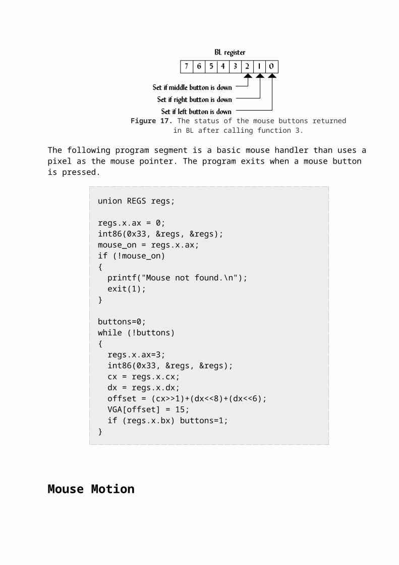
Mouse statusTo get the mouse's current status, set AX to 3 and call interrupt 0x33. The x value is returned in CX and the y value is returned in DX. BX contains the status of the mouse buttons (Figure 17).
Figure 17. The status of the mouse buttons returned in BL after calling function 3.
The following program segment is a basic mouse handler than uses a pixel as the mouse pointer. The program exits when a mouse button is pressed.
union REGS regs;
regs.x.ax = 0;int86(0x33, ®s, ®s);mouse_on = regs.x.ax;if (!mouse_on) { printf("Mouse not found.\n"); exit(1);}
buttons=0;while (!buttons){ regs.x.ax=3; int86(0x33, ®s, ®s); cx = regs.x.cx; dx = regs.x.dx; offset = (cx>>1)+(dx<<8)+(dx<<6); VGA[offset] = 15; if (regs.x.bx) buttons=1;}
Mouse Motion

Using the mouse driver's mouse position is easy, but it is not very portable to other video modes, like 320x240 or 640x480. An alternate way to keep track of the mouse position is to let the program do it, using function 0xB to get the motion that the mouse has moved. This function returns the motion the mouse has moved horizontally in CX, and the motion the mouse has moved vertically in DX. The following program segment uses function 0xB keep track of the mouse pointer. The loop exits when the mouse is placed in the upper-left corner.
union REGS reg;
x=160;y=100;while (x>0 || y>0){ /*... display mouse here ...*/
reg.x.ax=0x0B; int86(0x33,®s,®s); x += (int)reg.x.cx; y += (int)reg.x.dx; if (x<0) x=0; if (y<0) y=0; if (x>319) x=319; if (y>199) y=199;}
Mouse buttonsSometimes it does not matter if a mouse button is up or down, only if it was just pressed. With functions 5 and 6, instead of reading when a button is down, they read when a button is first pressed and finally released. To do this, set BX to the button (0=left, 1=right, 2=middle) and call interrupt 0x33. The function returns the number of presses or releases that have occurred in BX. The following code displays the status of the left button. The loop exits when the right button is released.
printf("Press right button to quit\n");do{ regs.x.ax=5; regs.x.bx=0; int86(0x33,®s,®s); if (regs.x.bx) printf("Left button pressed.\n"); regs.x.ax=6; regs.x.bx=0; int86(0x33,®s,®s); if (regs.x.bx)
printf("Left button released.\n"); regs.x.ax=6; regs.x.bx=1; int86(0x33,®s,®s);} while (!regs.x.bx)
AnimationIn a user-friendly interface, when the user selects a command that takes a while to execute, the mouse pointer might become an animated clock that lets the user know the computer is working. This technique is demonstrated in mouse.c. The mouse bitmap is stored in a structure that has a pointer to another mouse pointer, which is the next bitmap in the animation.
The vertical retrace is monitored to eliminate flickering of the mouse pointer as well.
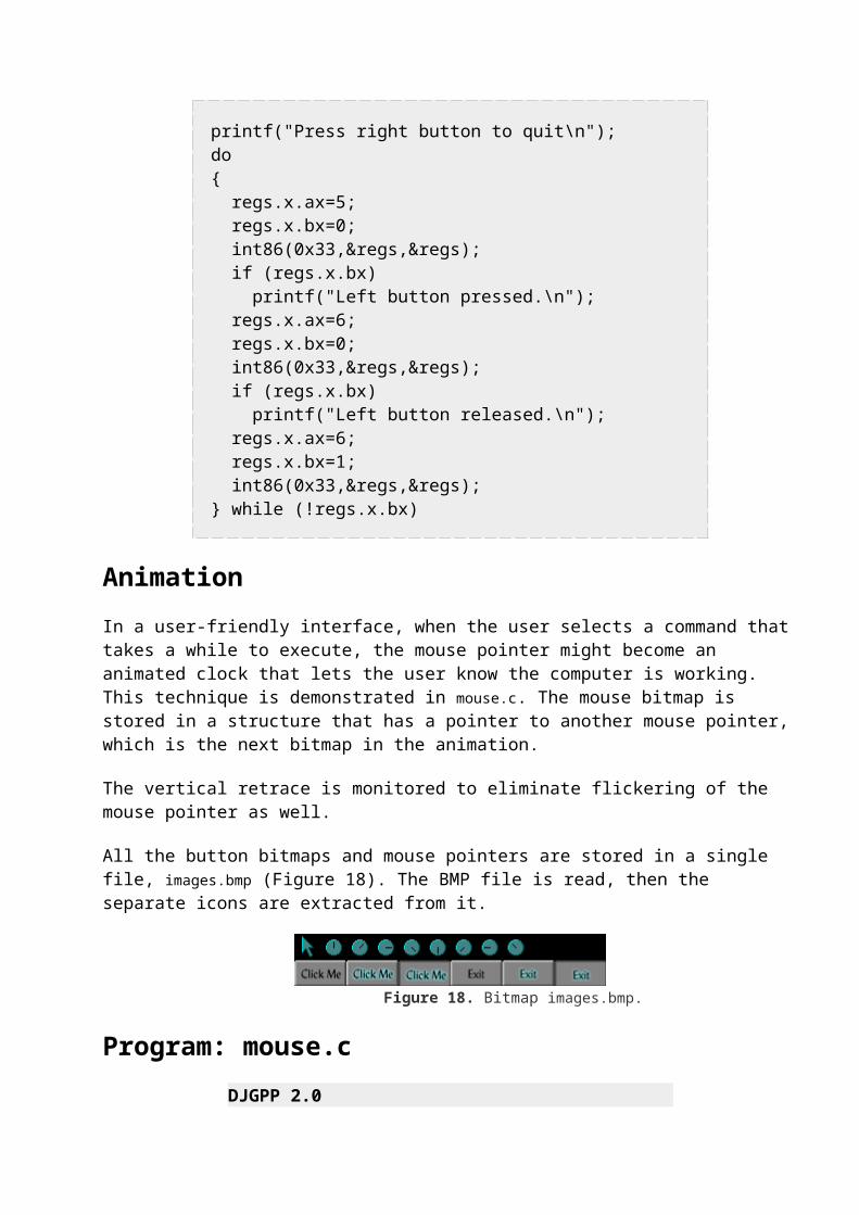
All the button bitmaps and mouse pointers are stored in a single file, images.bmp (Figure 18). The BMP file is read, then the separate icons are extracted from it.
Figure 18. Bitmap images.bmp.
Program: mouse.cDJGPP 2.0
View mouse.cDownload mouse.zip (Contains mouse.c, mouse.exe, images.bmp)
Borland C, Turbo C, etc.View mouse.cDownload mouse.zip (Contains mouse.c, mouse.exe, images.bmp)
Having trouble compiling or running the program? See the Troubleshooting page.
Figure 19. Output from mouse.exe.
The previous program is the most substantial program in this tutorial. It covers everything from this section and the previous section, and actually demonstrates a solid user interface, although the program does not do anything useful. With the ideas from these past three programs, a pull-down menu system could be created.
However, the scheme used to reduce flickering in this program is not very accurate at times. To create flicker-free programs, one of two techniques should be used: double buffering or page flipping. Both of these techniques are discussed in the next section.
Primitive Shapes & LinesContents in this section:
Why shapes and lines? Drawing lines Bresenham's algorithm Program: lines.c Drawing polygons Drawing rectangles Program: rect.c Using tables to speed up calculations
Fixed-point math Drawing circles Program: circle.c
Why shapes and lines?This section covers three basic drawing elements: lines, rectangles, and circles. Some of the programming techniques in this chapter may not appear to have any clear use, but the information here is a valuable resource and provides a good foundation.
Drawing linesOne problem with line drawing is that the screen is arranged in a grid of horizontal and vertical lines. A line drawn on the screen will cross both horizontal and vertical grid lines unless the line itself is either horizontal or vertical (Figure 4).
Figure 4. Drawing a line.
Therefore, the line drawn on the screen will not be exact; it will only be a representation of the line. The shaded areas in Figure 5 show the line drawn on a grid.
Figure 5. How the line appears on a grid.
One way to draw a line is to first calculate the slope of the line, then plot a pixel at each specified step along the major axis. To do this, we use a form of the point-slope equation of a line, which is
.
In the example in Figure 5, the major axis is the x axis because the line is more horizontal than vertical. The formula for the slope of a line is

.
Using (4,23) as (x1,y1) and (13,21) as (x2,y2),
.
Plot a pixel for each x 4 through 13 inclusive using the point-slope equation of a line. The first pixel plotted in this example is
,
or (4,23). The second, third and fourth pixels plotted is (5, 22.778), (6,22.556), and (7,22.333), or (5,23), (6,23), (7,22). See Table II for all the x and y values computed for this line.
Figure 6. Calculating the pixels plotted.
x y = slope(x-x1)+y1
4 -2/9(4-4) +23 = 235 -2/9(5-4) +23 = 22.778 = 236 -2/9(6-4) +23 = 22.556 = 237 -2/9(7-4) +23 = 22.333 = 228 -2/9(8-4) +23 = 22.111 = 229 -2/9(9-4) +23 = 21.889 = 2210 -2/9(10-4) +23 = 21.667 = 22
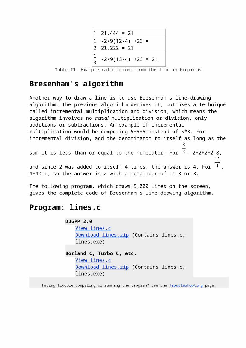
11 -2/9(11-4) +23 = 21.444 = 21
12 -2/9(12-4) +23 = 21.222 = 21
13 -2/9(13-4) +23 = 21
Table II. Example calculations from the line in Figure 6.

Bresenham's algorithmAnother way to draw a line is to use Bresenham's line-drawing algorithm. The previous algorithm derives it, but uses a technique called incremental multiplication and division, which means the algorithm involves no actual multiplication or division, only additions or subtractions. An example of incremental multiplication would be computing 5+5+5 instead of 5*3. For incremental division,
add the denominator to itself as long as the sum it is less than or equal to the numerator. For ,
2+2+2+2=8, and since 2 was added to itself 4 times, the answer is 4. For , 4+4<11, so the answer is 2 with a remainder of 11-8 or 3.
The following program, which draws 5,000 lines on the screen, gives the complete code of Bresenham's line-drawing algorithm.
Program: lines.cDJGPP 2.0
View lines.cDownload lines.zip (Contains lines.c, lines.exe)
Borland C, Turbo C, etc.View lines.cDownload lines.zip (Contains lines.c, lines.exe)
Having trouble compiling or running the program? See the Troubleshooting page.
Figure 7. Screenshot of lines.exe.
The results from lines.exe were as follows:
Slow line drawing took 4.285714 seconds.Fast line drawing took 1.758242 seconds.Fast line drawing was 2.437500 times faster.

The reason Bresenham's line drawing algorithm is faster is that it uses no multiplication or division. Multiplication and division are slow on a computer, even on a computer with a math coprocessor.
Drawing polygonsUsing the line-drawing function from the lines.c program, a polygon function can easily be created. The following code segment demonstrates this.
void polygon(int num_vertices, int *vertices, byte color) { int i;
for(i=0;i<num_vertices-1;i++) { line(vertices[(i<<1)+0], vertices[(i<<1)+1], vertices[(i<<1)+2], vertices[(i<<1)+3], color); } line(vertices[0], vertices[1], vertices[(num_vertices<<1)-2], vertices[(num_vertices<<1)-1], color);}
The polygon function could be used to draw a triangle as follows:
int num_vertices=3;int vertices[6]={5,0, /* (x1,y1) */ 7,5, /* (x2,y2) */ 1,4}; /* (x3,y3) */polygon(3,vertices,15);
Drawing rectanglesAlthough this function is very flexible, it is not suitable for simple shapes like rectangles because rectangles are drawn with horizontal and vertical lines. The line-drawing function is not optimized for drawing those types of lines. Vertical and horizontal line drawing is as simple as plotting a pixel and incrementing the pointer to video memory. The program rect.c shows the difference between drawing rectangles using a previously created function and drawing rectangles from scratch. It also illustrates drawing solid rectangles.

Program: rect.cDJGPP 2.0
View rect.cDownload rect.zip (Contains rect.c, rect.exe)
Borland C, Turbo C, etc.View rect.cDownload rect.zip (Contains rect.c, rect.exe)
Having trouble compiling or running the program? See the Troubleshooting page.
Figure 8. Screenshot of rect.exe.
Slow rectangle drawing took 4.230769 seconds.Fast rectangle drawing took 1.153846 seconds.Fast rectangle drawing was 3.666667 times faster.
Rectangle fills are one of more useful things when programming a graphical user interface. Circles, on the other hand, are not as common, but are described in the following sections to help the reader understand some important programming techniques that are used in many different applications.
Using tables to speed up calculationsIn some applications, like drawing curves or animation, certain math functions like cosine and sine are used. On problem with these functions is that they are slow because of the time it takes the computer to calculate them. Not only that, but certain angles may be called more than once,
like , so the computer has to calculate them multiple times.
To overcome this problem, tables can be used. When the program starts up, the sine and cosine of every angle is stored in an array:
#include <math.h>...
float COS_TABLE[360], SIN_TABLE[360];float pi=3.14159;...for(i=0;i<360;i++){ COS_TABLE[i]=cos((float)i/180 * pi); SIN_TABLE[i]=sin((float)i/180 * pi);}
In this example, the angles are mapped from zero to 359, but they could be mapped in any way. A common mapping is zero to 255 because it fits in one byte. Also, tables are not limited to just sine and cosine functions. The table used in the program circle.c is more complex than sine or cosine, and is mapped from 0 to 1023.
Fixed-point mathIn many situations, like the one in the previous example, floating point numbers are used. Floating point numbers are very accurate on computers, but are very slow when multiplication or other math functions are used on them.
An alternative to floating point numbers are fixed-point numbers. Fixed point numbers are faster than floating point, but are not as accurate. The accuracy is suitable for most applications involving VGA graphics, however.
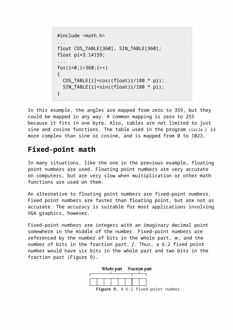
Fixed-point numbers are integers with an imaginary decimal point somewhere in the middle of the number. Fixed-point numbers are referenced by the number of bits in the whole part, w, and the number of bits in the fraction part, f. Thus, a 6:2 fixed point number would have six bits in the whole part and two bits in the fraction part (Figure 9).
Figure 9. A 6:2 fixed-point number.
To assign floating point values to fixed point numbers, multiply the floating point number by 2f:
unsigned char a,b,c;...whole_part=6;fraction_part=2;a=14.75 * (1<<fraction_part);b=32.5 * (1<<fraction_part);
To display a fixed point number, divide the fixed point number by 2f.

printf("a=%f",(float)a / (1<<fraction_part));
Adding or subtracting fixed point numbers is the same as adding or subtracting two integers. For example, 001110.11 + 100000.10 = 101111.01, or 14.75 + 32.5 = 47.25.
c=a+b;printf("a*b=%f\n",(float)c/4);
Multiplying two fixed point numbers is different: both the whole part and the fraction part will double in length. For example, multiplying two 6:2 fixed-point numbers generates a 12:4 number. The solution to this problem is to shift the number right by f bits, and ignore the upper w bits of the product.
c=(a*b) >> fraction_part;
The program circle.c uses 16:16 fixed-point numbers to increase the speed of drawing circles.
Drawing circlesA simple way to draw a circle is to divide it into octants (Figure 10). First calculate only one octant of the circle; the rest of the circle is “mirrored” from the first octant.
Figure 10. Dividing a circle into octants to reduce computation.
A formula for finding points along a common radius, like that of a circle, is
(x, y) = (r cos , r sin ),
where r is the radius of the circle and is the angle at which to plot the point. This formula is changed to
, ,
which is reduced to
.
This formula is used to find the y value for an x value and a radius. If the first octant calculated is octant 1, the x value starts at zero and increments, calculating y for every x. The loop finishes when x>y (Figure 11). The rest of the circle is mirrored from octant 1.
Figure 11. The arc is drawn in Octant 1 for all 0<=x<= y.
Program: circle.cThis is not the fastest algorithm for drawing circles, but is used in the following program to demonstrate using tables and fixed-point numbers. circle.c also demonstrates drawing filled circles.
DJGPP 2.0View circle.cDownload circle.zip (Contains circle.c, circle.exe)
Borland C, Turbo C, etc.View circle.cDownload circle.zip (Contains circle.c, circle.exe)
Having trouble compiling or running the program? See the Troubleshooting page.
Figure 12. Screenshot of circle.exe.

Slow circle drawing took 6.868132 seconds.Fast circle drawing took 1.098901 seconds.Fast circle drawing was 6.249999 times faster.
Something noticeable about the output from circle.exe is that the circles do not appear as circles, they appear as ellipses. This is because of the odd aspect ratio of mode 0x13. Instead of a 4:3 aspect ratio, it has an 8:5 aspect ratio, which looks distorted on a screen. To overcome this, a circle's width must be 1.2 times longer than its height. This is also something to consider when drawing bitmaps; the next section covers bitmaps.
VGA BasicsContents in this section:
What is VGA? Structure of mode 0x13 Setting the video mode Plotting a pixel Mode 0x13 memory Plotting a pixel quickly Program: pixel.c Shifting
View the Belorussian translation of this tutorial
What is VGA?VGA stands for Video Graphics Array, sometimes referred to as Video Graphics Adapter. It is a video card, which is an interface between a computer and its corresponding monitor. The VGA card
is the most common video card — nearly every video card has VGA compatibility — and it is fairly easy to program. It offers many different video modes, from 2 color to 256 color, and resolutions from 320x200 to 640x480. This tutorial pays close attention to the VGA's only 256-color mode, known as mode 0x13.
Structure of mode 0x13In mode 0x13, the screen dimensions are 320 pixels in width and 200 pixels in height. This is mapped 0 to 319 on the x axis and 0 to 199 on the y axis, with the origin (0,0) at the top-left corner (Figure 1). Since this is a 256-color mode, each pixel represents 8 bits (28=256) or one byte, so the memory needed is 320*200 or 64,000 bytes.
Figure 1. Structure of Mode 0x13.
Setting the video modeTo set the video mode, call interrupt 0x10 (BIOS video functions) with 0 (zero) in the AH register and the desired mode number in the AL register. For mode 0x13, the code (Borland C) would be as follows:
union REGS regs;
regs.h.ah = 0x00; /* function 00h = mode set */regs.h.al = 0x13; /* 256-color */int86(0x10,®s,®s); /* do it! */
To return to text mode after the program finishes, simply set the mode number to 3.
union REGS regs;

regs.h.ah = 0x00;regs.h.al = 0x03; /* text mode is mode 3 */int86(0x10,®s,®s);
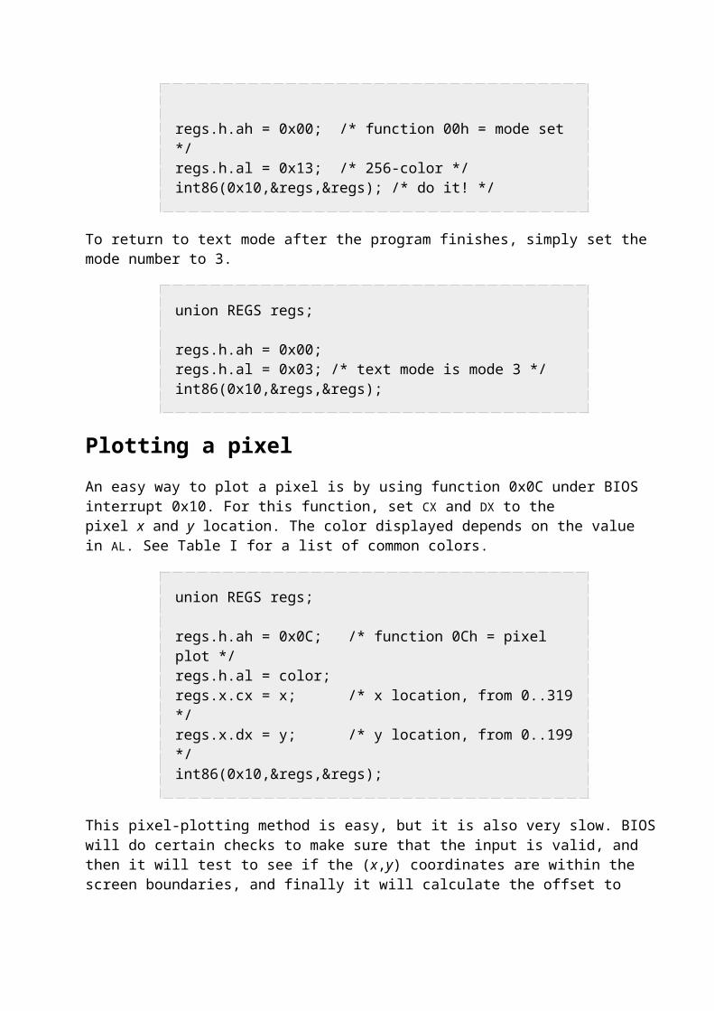
Plotting a pixelAn easy way to plot a pixel is by using function 0x0C under BIOS interrupt 0x10. For this function, set CX and DX to the pixel x and y location. The color displayed depends on the value in AL. See Table I for a list of common colors.
union REGS regs;
regs.h.ah = 0x0C; /* function 0Ch = pixel plot */regs.h.al = color;regs.x.cx = x; /* x location, from 0..319 */regs.x.dx = y; /* y location, from 0..199 */int86(0x10,®s,®s);
This pixel-plotting method is easy, but it is also very slow. BIOS will do certain checks to make sure that the input is valid, and then it will test to see if the (x,y) coordinates are within the screen boundaries, and finally it will calculate the offset to video memory. A faster way to plot a pixel is to write directly to video memory.
Mode 0x13 memoryAs mentioned before, the memory needed for mode 0x13 is 64,000 bytes. This memory is located at segment 0xA000 in the computer's memory. Simply writing to that area in memory will also write to the screen. The color displayed depends on the byte value written to memory.
Value Color0 Black1 Blue2 Green3 Cyan4 Red5 Magenta6 Brown7 Light Gray8 Dark Gray9 Light Blue

10 Light Green11 Light Cyan12 Light Red13 Light Magenta14 Yellow15 White
Table I. The first 16 VGA colors.
Since memory is linear (unlike the computer screen, which has both an x and a y dimension), the offset into computer memory must be calculated to plot a pixel. To do this the y value is multiplied by the width of the screen, or 320, and the x value is added to that. Thus to plot a pixel at location (256,8), first calculate 256+8*320=2816 or 0xB00, then write to segment 0xA000, offset 0xB00. The following program segment creates a pointer to address 0xA000:0000, computes the offset from two variables, and then writes to the calculated memory location.
Plotting a pixel quickly
typedef unsigned char byte;byte far *VGA = (byte far*)0xA0000000L; unsigned short offset;...offset = 320*y + x;VGA[offset] = color;
The previous code has the following characteristics:
The variable offset must be an unsigned short data type (16 bits with a range from 0 to 65,535) because the size of memory needed for mode 0x13 is 64,000 bytes. Using an unsigned short data type helps insure that we won't accidently write to an area of memory that isn't part of the video memory, which might cause our program to crash.
If y were 5 and x were 340, the pixel would be displayed at (20,6), since video memory in mode 0x13 is linear, and the width of the screen is only 320. The BIOS function would not display a pixel on the screen for (340,5) since it clips to the screen boundaries.
The pointer to the VGA memory segment must be far when compiled in the smaller memory modules. If the memory module used is COMPACT, LARGE, or HUGE, then the far keyword can be removed.
In most DOS extenders, the 32-bit protected mode pointer to video memory would be 0xA0000 instead of the segment-offset pointer 0xA0000000L.
Program: pixel.c

The following program demonstrates how much faster writing directly to video memory is. It plots 50,000 pixels using BIOS, then does the same by writing directly to video memory, and then displays the results.
DJGPP 2.0View pixel.cDownload pixel.zip (Contains pixel.c, pixel.exe)
Borland C, Turbo C, etc.View pixel.cDownload pixel.zip (Contains pixel.c, pixel.exe)
Having trouble compiling or running the program? See the Troubleshooting page.
Figure 2. Screenshot of pixel.exe.
This program, along with all other programs in this tutorial, ran on a 486dx 33Mhz with 8MB of memory, 128KB cache, and a 16-bit ISA SVGA card. The results frompixel.exe on this computer were as follows:
Slow pixel plotting took 3.846154 seconds.Fast pixel plotting took 0.989011 seconds.Fast pixel plotting was 3.888889 times faster.
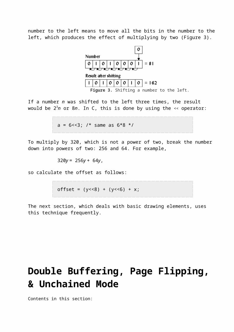
ShiftingA way to further speed up pixel plotting is to use shifting instead of multiplication when calculating the offset. Shifting a number to the left means to move all the bits in the number to the left, which produces the effect of multiplying by two (Figure 3).

Figure 3. Shifting a number to the left.
If a number n was shifted to the left three times, the result would be 23n or 8n. In C, this is done by using the << operator:
a = 6<<3; /* same as 6*8 */
To multiply by 320, which is not a power of two, break the number down into powers of two: 256 and 64. For example,
320y = 256y + 64y,
so calculate the offset as follows:
offset = (y<<8) + (y<<6) + x;
The next section, which deals with basic drawing elements, uses this technique frequently.
Double Buffering, Page Flipping, & Unchained ModeContents in this section:
Why double buffering and/or page flipping? Double buffering Page flipping Structure of unchained mode Tweaking mode 0x13 Plotting a pixel in unchained mode Page flipping in unchained mode Program: unchain.c Other unchained modes Program: modes.c
Why double buffering and/or page flipping?

Two important concepts used in many games and multimedia applications are double buffering and page flipping. Programmers primarily use these techniques for two purposes:
to keep the user from seeing objects being drawn onto the screen to eliminate flickering.
Double bufferingDouble Buffering is a fairly simple concept to grasp. Instead of drawing directly to video memory, the program draws everything to a double buffer (Figure 20a). When finished, the program copies the double buffer to video memory all at once (Figure 20b). At that point the program clears the double buffer (if necessary) and the process starts over.
Figure 20. Double buffering concept.
Implementing a double buffer is fairly simple as well. The double buffer is generally the same size as the screen. In mode 0x13, the double buffer would be 64,000 bytes. When the program begins it allocates memory for the double buffer.
unsigned char *double_buffer;
...
double_buffer = (unsigned char *) malloc(320*200);if (double_buffer==NULL){ printf("Not enough memory for double buffer.\n");
exit(1);}
Then, instead of writing to video memory, the program writes to the double buffer.
/* plot a pixel in the double buffer */double_buffer[(y<<8) + (y<<6) + x] = color;
When finished, the program copies the double buffer to video memory (with careful consideration of the vertical retrace to eliminate flickering).
while ((inp(INPUT_STATUS_1) & VRETRACE));while (!(inp(INPUT_STATUS_1) & VRETRACE));memcpy(VGA,double_buffer,320*200);
Using a double buffer would be faster if, instead of having to copy the information from the double buffer to video memory (address 0xA000:0000), the video card could be programmed to get video data directly from the double buffer rather than from its regular address (0xA000:0000). While this is not possible on the VGA, it is close to how page flipping works.
Page flippingWith page flipping, there must be enough video memory for two screens. So, if the screen size is 320x200 at 256 colors, 2*320*200 or 128,000 bytes of video memory must be available. Instead of drawing to the visible area in video memory, or visible page, the program draws to the non-visible page (Figure 21a). When finished, the program swaps the visible page pointer with the non-visible page pointer (Figure 21b). Now the program clears the newly placed non-visible page (if necessary) and the process starts over.
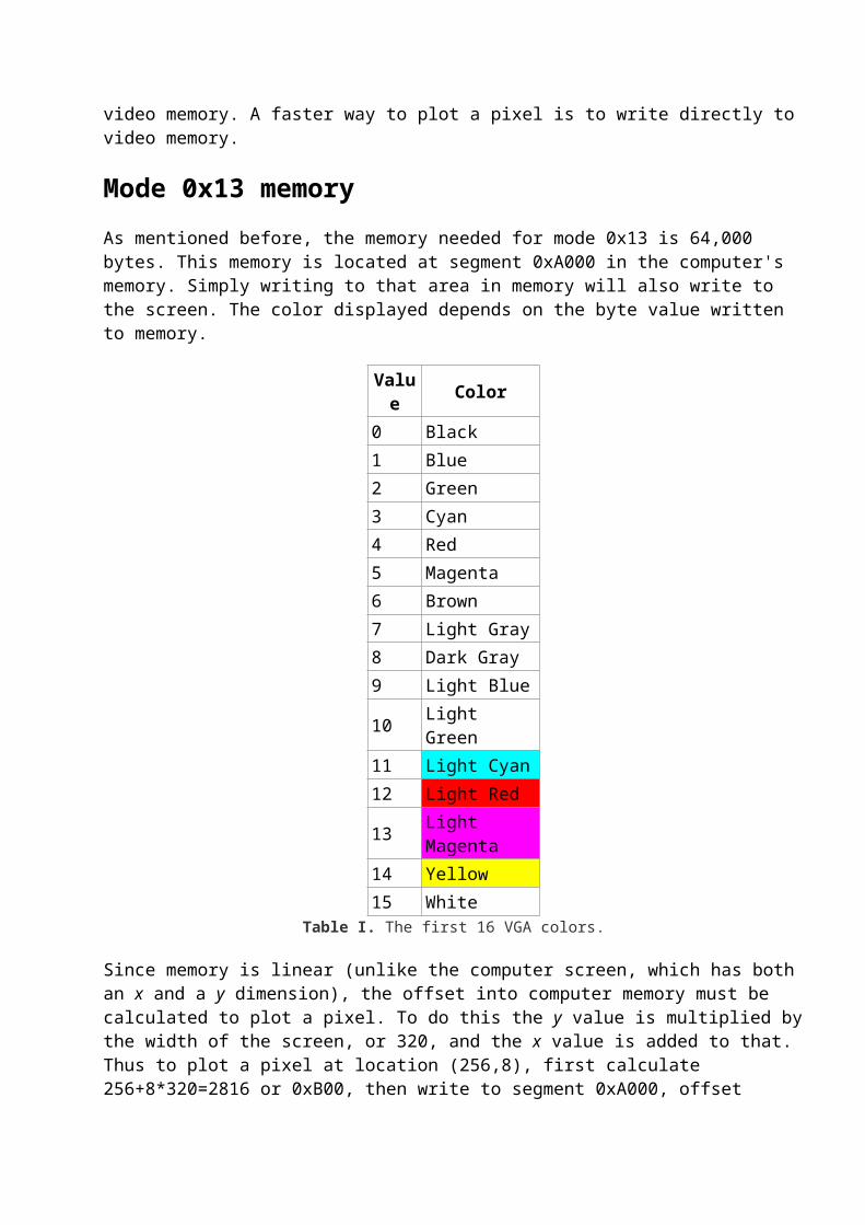
Figure 21. Page flipping concept.
One problem is this: in mode 0x13, only 64K of video memory is available, even if the video card has more memory on it. Even if it is a 4MB video card, mode 0x13 can only access 64K. There is a way, however, to tweak mode 0x13 into a 256-color mode that has a total of 256K of video memory, so that page flipping is possible. This undocumented mode is sometimes referred to as “mode-x,” or “unchained mode.”
Structure of unchained modeThe VGA card has 256K of memory. Many SVGA cards have much more, but even on those cards, VGA modes can only access the first 256K-except for mode 0x13, which can only access 64K. The reason is that mode 0x13 is a chain-4 mode, which basically means only every forth byte of video memory is used. The reason for this is because the linear structure of the video memory allowed fast and easy video memory access. Turning off chain-4 mode allows the program to access of all 256K of video memory, but involves more complicated programming.
In unchained mode, memory exists in four 64K planes. Each plane corresponds to a specific column of video memory: plane 0 contains pixels 0, 4, 8, etc.; plane 1 contains pixels 1, 5, 9, etc.; plane 2 contains columns 2, 6, 10, etc.; and plane 3 contains columns 3, 7, 11, etc. (Figure 22). So to plot a pixel at position (5,7), plane 1 is selected, and the offset is (320*7+5)/4 = 561.
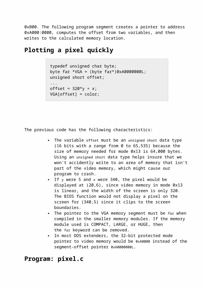
Figure 22. How video memory relates to the screen.
Tweaking mode 0x13Since unchained mode is not a standard VGA mode, it cannot be set using a BIOS function call. Instead, certain VGA registers have to be tweaked. It involves two VGA controllers: the sequence controller (port 0x3C4) and the CRT controller (port 0x3D4).
/* VGA sequence controller */#define SC_INDEX 0x03c4#define SC_DATA 0x03c5
/* VGA CRT controller */#define CRTC_INDEX 0x03d4#define CRTC_DATA 0x03d5
#define MEMORY_MODE 0x04#define UNDERLINE_LOC 0x14#define MODE_CONTROL 0x17
...
/* turn off chain-4 mode */outp(SC_INDEX, MEMORY_MODE);outp(SC_DATA, 0x06);
/* TODO: Insert code to clear the screen here. (the BIOS only sets every fourth byte to zero -- the rest needs to be set to zero, too) */

/* turn off long mode */outp(CRTC_INDEX, UNDERLINE_LOC);outp(CRTC_DATA, 0x00);/* turn on byte mode */outp(CRTC_INDEX, MODE_CONTROL);outp(CRTC_DATA, 0xe3);
The VGA registers can sometimes be fairly complex. For a complete list of the VGA registers, visit PC-GPE Online.
Plotting a pixel in unchained modePlotting a pixel in unchained mode is a tad bit more tedious than it is in mode 0x13, because the proper plane has to be selected. To select a plane, write 2plane to the VGA Map Mask register, where plane is a value from 0 to 3 (Figure 23).
Figure 23. Selecting a plane with the Map Mask register.
The Map Mask register is located at index 2 of the Sequence Controller. To select the Map Mask register, write 2 to the Sequence Controller address at port 0x3C4. Then the Map Mask can be found at the Sequence Controller's data port at port 0x3C5.
plane = (x&3);/* select the map mask register */outp(0x3c4, 0x02);/* write 2^plane */outp(0x3c5, 1 << plane);
In mode 0x13, the offset is calculated as 320y + x. Since unchained mode memory is arranged in
four planes, the offset in unchained mode is calculated as (Figure 22).
VGA[(y<<6) + (y<<4) + (x>>2)] = color;
If a value other than a power of two was used to select a plane, multiple planes would be selected. For example, if 13 (binary 1101) were used, planes 0, 2, and 3 would be selected. That means every plane selected is written with the color value. One use for this is fast screen-clearing. If every plane is selected, only 16,000 bytes need to be written, instead of 64,000 like in mode 0x13.
/* set map mask to all 4 planes */outpw(0x3c4, 0xff02);memset(VGA,0, 16000);
Page flipping in unchained modeFirst, set up two word-sized variables to keep track of the visible and non-visible pages. These are offsets to video memory.
unsigned int visible_page=0;unsigned int non_visible_page=320*200/4;
Then do all the drawing to the non-visible page. For instance, if a pixel was to be plotted:
/* select plane */outp(SC_INDEX, MAP_MASK);outp(SC_DATA, 1 << (x&3) );
VGA[non_visible_page+(y<<6)+(y<<4)+(x>>2)]=color;
When all the drawing is finished, it is time to switch the pages. The new offset is set through two registers on the CRT controller. The first, 0x0C, sets the upper 8-bits of the offset, and the second, 0x0D, sets the lower 8-bits.
/* CRT controller registers */#define HIGH_ADDRESS 0x0C#define LOW_ADDRESS 0x0D
...
temp = visible_page;visible_page = non_visible_page;non_visible_page = temp;
high_addr=HIGH_ADDRESS | (visible_page & 0xff00);low_addr =LOW_ADDRESS | (visible_page << 8);
while ((inp(INPUT_STATUS_1) & VRETRACE));outpw(CRTC_INDEX, high_addr);outpw(CRTC_INDEX, low_addr);
while (!(inp(INPUT_STATUS_1) & VRETRACE));
Here are some things to consider when using page flipping:
If the program was using interrupts, it would be advisable to disable interrupts before the page was flipped and re-enable them afterward. If an interrupt occurred at the wrong time, the screen could be temporarily distorted.
When the offset registers are changed, the page flip does not occur until the end of the next vertical retrace. So after the page is flipped, the program should wait until the end of the vertical retrace before drawing to the non-visible page.
In the following program, instead of referring to the pages as visible and non-visible refers to them as visual and active. It draws animated balls (Figure 24) around the screen using both double buffering and page flipping, and then outputs the results. It defaults to drawing eight balls; a unique number of balls can be drawn by specifying a number at the command prompt. In this example, 16 balls were drawn by using the command unchain 16.
Figure 24. Bitmap balls.bmp.
Program: unchain.cDJGPP 2.0
View unchain.cDownload unchain.zip (Contains unchain.c, unchain.exe, balls.bmp)
Borland C, Turbo C, etc.View unchain.cDownload unchain.zip (Contains unchain.c, unchain.exe, balls.bmp)
Having trouble compiling or running the program? See the Troubleshooting page.
Figure 25. Output from unchain.exe.

Results with 16 objects: Mode 0x13 with double buffering: 5.989011 seconds, 23.376147 frames per second. Unchained mode with page flipping: 4.065934 seconds, 34.432431 frames per second. Unchained mode with page flipping was 1.472973 times faster.
Although page flipping in unchained mode was faster than double buffering in mode 0x13 in this example, it is not always faster. This program was created to prove a point: depending on the number of pixels drawn and the number of outp()'s or outpw()'s used in unchained mode, mode 0x13 can still be faster. The program was tested (ignoring the vertical retrace) on various numbers of objects to show the relationship (Figure 26).
Figure 26. Unchained mode is not always faster.
One of the reasons mode 0x13 is sometimes faster than unchained mode is that for each frame, the selected plane is changed four times for each ball object. The program could have been created to select the plane only four times per frame, which would have increased performance, because outp()'s and outpw()'s are very slow statements. When designing a program for unchained mode, the number of outp()'s and outpw()'s used should be limited to as few as possible.
Other unchained modesThe code below will someday be included in another section of this site, but right know it's just here to show you how to program the different unchained modes, like 320x240 and 360x480.
Program: modes.c

This program demonstrates various unchained modes. It supports widths of 320 and 360, and heights of 200, 400, 240, and 480, so there are a total of eight combinations. Setting the mode you want is done like so:
set_unchained_mode(320,240);
The program also demonstrates planar bitmaps, which speeds things up a bit. Make sure you download ghosts.bmp to get the program to work.
DJGPP 2.0View modes.cDownload modes.zip (Contains modes.c, modes.exe, ghosts.bmp)
Borland C, Turbo C, etc.View modes.cDownload modes.zip (Contains modes.c, modes.exe, ghosts.bmp)
Having trouble compiling or running the program? See the Troubleshooting page.