mentor.ieee.org · web viewabstract. this submission proposes resolutions for cids 7177, 7202,...
TRANSCRIPT

May, 2016 doc.: IEEE 802.11-16/0276r7
IEEE P802.11Wireless LANs
Resolutions for some comments on 11mc/D5.0 (SBmc1)
Date: 2016-054-0627
Author(s):Name Affiliation Address Phone email
Mark RISON Samsung Cambridge Solution Centre SJH, CB4 0DS, U.K. +44 1223 434600
at samsung (a global commercial entity) I'm the letter emme
then dot rison
Submission page 1
AbstractThis submission proposes resolutions for CIDs 7177, 7202, 7208, 7213, 7255, 7277, 7278, 7280-7290, 7292, 7294, 7295, 7296, 7320, 7347, 7349, 7376, 7377, 7379, 7393, 7396, 7399, 7400, 7419, 7427, 7429, 7468, 7477, 7478, 7484, 7499, 7500, 7504, 7527, 7529, 7532, 7549, 7572, 7595, 7596, 7597, 7603, 7604, 7608, 7635, 7746, 7774, 7776, 7795, 7796 on 11mc/D5.0. Green indicates material agreed to in the group, yellow material to be discussed, red material rejected by the group and cyan material not to be overlooked. The “Final” view should be selected in Word.
r1: changes made during BRC meeting on 2016-02-22. Added CIDs 7349, 7429.
r2: changes made during BRC meeting on 2016-02-23. Amended CID 7177 (previously agreed). Added CIDs 7347, 7376, 7527.
r3: changes made during BRC meeting on 2016-02-25. Updated CIDs 7292, 7608. Added CIDs 7208, 7213, 7255, 7277, 7278, 7280-7290, 7377, 7393, 7484, 7635. Added an extra resolution for mc/D4.0 CID 6431.
r4: changes made prior to BRC meeting on 2016-04-15. Updated CIDs 7177, 7208, 7278, 7280-7290, 7292, 7396, 7398-7400, 7478. Added CIDs 7294, 7295, 7296, 7774, 7776.
r5: changes made during and between BRC meetings on 2016-04-15 and 2016-04-21.
r6: changes made during and after BRC meetings on 2016-04-25, 2016-04-26 and 2016-04-27.
r7: changes made during and after BRC meeting on 2016-04-27.

May, 2016 doc.: IEEE 802.11-16/0276r7
Identifiers Comment Proposed changeCID 7177Mark RISON10.161342.21
In order to reduce power consumption, there should be a dynamic mechanism to request to a peer that it not transmit to the requesting device using LDPC
Add a mechanism, based on extending Operating Mode Notification or otherwise
Discussion:
LDPC provides additional link margin, but is very computationally intensive on receive compared with BCC, and hence significantly less power-efficient. It is therefore desirable for a receiver to be able to indicate to a transmitter that LDPC need not be used.
This can be done by extending the Operating Mode Notification element. Unfortunately, this has no reserved bits left. Fortunately, this is extensible. Unfortunately, the Operating Mode Notification frame is not trivially extensible, as it uses the Operating Mode field rather than the Operating Mode Notification element, and it might be followed by VSIEs etc.
Proposed changes:
Change 9.4.2.166 as follows:
9.4.2.166 Operating Mode Notification element
The Operating Mode Notification element is used to notify STAs that the transmitting STA is changing one or more of its operating channel width, the maximum number of spatial streams it can receive, or bothand its LDPC receive preference. The format of the Operating Mode Notification element is defined in Figure 9-570 (Operating Mode Notification element).
Editor: In Figure 9-570—Operating Mode Notification element add a cell on the right saying “Extended Operating Mode” and show this as 0 or 1 octets.
The Element ID and Length fields are defined in 9.4.2.1 (General).
The Operating Mode field is defined in 9.4.1.53 (Operating Mode field).
The Extended Operating Mode field is defined in 9.4.1.53b (Extended Operating Mode field) and is optional.
Add a new Subclause 9.4.1.53b as follows:
9.4.1.53b Extended Operating Mode field
The Extended Operating Mode field is optionally present in the Operating Mode Notification element (see 9.4.2.166 (Operating Mode Notification element)) and is present in the Extended Operating Mode Notification element (see 9.4.2.166b (Extended Operating Mode Notification element)) that is optionally present in the Operating Mode Notification frame (see 9.6.23.4 (Operating Mode Notification frame format)).
The Extended Operating Mode field is shown in Figure 9-117b (Extended Operating Mode field).
Editor: Insert a figure like Figure 9-117 but with just a b0 saying “No LDPC” and b1-b7 reserved.
Submission page 2

May, 2016 doc.: IEEE 802.11-16/0276r7
The No LDPC field is set to 1 to indicate that the STA transmitting this field prefers not to receive LDPC-encoded PPDUs; it is set to 0 otherwise.
Add a new row to Table 9-76—Element IDs:
Extended Operating Mode Notification (see 9.4.2.166b (Extended Operating Mode Notification element))
<ANA> <ANA> Yes
Add a new Subclause 9.4.2.166b as follows:
9.4.2.166b Extended Operating Mode Notification element
The Extended Operating Mode Notification element is used to notify STAs that the transmitting STA is changing its LDPC receive preference. The format of the Extended Operating Mode Notification element is defined in Figure 9-570b (Extended Operating Mode Notification element).
Editor: Copy Figure 9-570 as Figure 9-570b here, changing “Operating Mode” to “Extended Operating Mode” and adding a 1-octet Element ID Extension field after the Length field.
The Element ID, Element ID Extension and Length fields are defined in 9.4.2.1 (General).
The Extended Operating Mode field is defined in 9.4.1.53b (Extended Operating Mode field).
Change the start of 9.6.23.4 as follows:
9.6.23.4 Operating Mode Notification frame format
The Operating Mode Notification frame is an Action frame of category VHT. It is used to notify STAs that the transmitting STA is changing one or more of its operating channel width, the maximum number of spatial streams it can receive, or bothand its LDPC receive preference.
Add a row at the end of Table 9-417—Operating Mode Notification frame Action field format:
4 Zero or one Extended Operating Mode Notification element
Add the following as the penultimate paragraph of 10.16 LDPC operation:
A STA should not transmit a frame with the TXVECTOR parameter FORMAT set to HT_MF, HT_GF or VHT and the TXVECTOR parameter FEC_CODING set to LDPC_CODING if the RA of the frame corresponds to a STA from which it has received a frame containing an Extended Operating Mode field and the most recent frame with an Operating Mode field it has received from that STA had an Extended Operating Mode field with the No LDPC subfield equal to 1.
Proposed resolution:
REVISED
Make the changes shown under “Proposed changes” for CID 7177 in <this document>, which effect the requested addition.
Submission page 3

May, 2016 doc.: IEEE 802.11-16/0276r7
Identifiers Comment Proposed changeCID 7379Mark RISON11.24.6.31766.56
"In the case of requests for 160 MHz bandwidth, the initiating STA can indicate whether it uses a single or two separate RF LOs." -- it not only can but shall (i.e. it shall not lie). Ditto the rSTA shall so indicate
Change "can" to "shall" and extend the statement to cover the responding STA too
Discussion:
It is important for maximum FTM accuracy that both sides know whether the other side is using separate LOs.
Proposed changes:
Change from 1766.56 as follows:
In the case of requests for 160 MHz bandwidth, the initiating STA shallcan indicate in the FTM Format and Bandwidth field whether it uses a single or two separate RF LOs. In the cases when the responding STA indicates advertises use of transmission of Fine Timing Measurement frames with 160 MHz bandwidthtransmissions, the responding STA shall indicate in the FTM Format and Bandwidth field whether it uses a single or two separate RF LOs.chooses the appropriate entry in the FTM Format and Bandwidth field depending on the number of RF LOs used by the responding STA.
Proposed resolution:
REVISED
Make the changes shown under “Proposed changes” for CID 7379 in <this document>, which effect the requested change.
Submission page 4

May, 2016 doc.: IEEE 802.11-16/0276r7
Identifiers Comment Proposed changeCID 7396Mark RISON10.3.2.91281.32
"After transmitting an MPDU that requires an Ack frame as a response (see Annex G), the STA shall wait for an AckTimeout interval" -- isn't a BA analogue of this needed?
Extend this para to cover the case where a BA is required
Discussion:
There are detailed rules, including rules on error-handling, for Acks in 10.3.2.9. However, there are almost no rules for BlockAcks in 10.3.2.10.
Proposed changes:
Change 10.3.2.9 and 10.3.2.10 as follows (note that CID 7089 might make changes here too):
10.3.2.9 Acknowledgement procedure
The cases when an Ack or BlockAck frame can be generated are shown in the frame exchange sequences listed in Annex G.
A STA shall not transmit an Ack or BlockAck frame in response to On receipt of a Management frame of subtype Action No Ack, a STA shall not send an Ack frame in response. A non-AP STA shall not transmit an Ack or BlockAck frame in response to a group addressed frame.NOTE 1—Group addressed MSDUs are sent to an AP in individually addressed frames.
Otherwise, uUpon reception of a frame of a type that requires acknowledgment and, for an AP, with the To DS subfield equal to 1 set, an STAAP shall transmitgenerate an Ack or BlockAck frame. An Ack frame shall be transmitted by the destination non-AP STA when it successfully receives an individually addressed frame of a type that requires acknowledgment, but not if it receives a group addressed frame of such type. After a reception of a frame requiring acknowledgment, transmission of the Ack frame shall commence after a SIFS, without regard to the busy/idle state of the medium. (See Figure 10-10 (Individually addressed data/Ack frame).)
Editor: in Figure 10-10 change “Ack” to “Ack/BA” twice (once in figure and once in caption).
After transmitting an MPDU that requires an Ack or BlockAck frame as a response (see Annex G), the STA shall wait for an AckTimeout interval, with a value of aSIFSTime + aSlotTime + aRxPHYStartDelay. This interval begins when the MAC receives a PHY-TXEND.confirm primitive. If a PHY-RXSTART.indication primitive does not occur during the AckTimeout interval, the STA concludes that the transmission of the MPDU has failed, and this STA shall invoke its backoff procedure upon expiration of the AckTimeout interval. If a PHY-RXSTART.indication primitive does occur during the AckTimeout interval, the STA shall wait for the corresponding PHY-RXEND.indication primitive to determine whether the MPDU transmission was successful. The recognition of a valid Ack or BlockAck frame sent by the recipient of the MPDU requiring acknowledgment, corresponding to this PHY-RXEND.indication primitive, shall be interpreted as successful acknowledgment, permitting the frame exchange sequence to continue, or to end without retries, as appropriate for the particular frame exchange sequence in progress. The recognition of anything else, including any other valid frame, shall be interpreted as failure of the MPDU transmission. In this instance, the STA shall invoke its backoff procedure at the PHY-RXEND.indication primitive and may process the received frame. An exception is that recognition of a valid Data or Management frame sent by the recipient of a PS-Poll frame shall also be accepted as successful acknowledgment of the PS-Poll frame.
NOTE 12—The backoff procedure in the specific case of reception of a corrupted Ack or BlockAck frame results in EIFS rather than DIFS or AIFS being used after the AckTimeout interval and subsequent reception of the corrupted
Submission page 5

May, 2016 doc.: IEEE 802.11-16/0276r7
Ack or BlockAck frame (see 10.3.4.3 (Backoff procedure for DCF) and 10.22.2.4 (Obtaining an EDCA TXOP) respectively).
NOTE 23—The receiver STA performs the acknowledgementAck procedure on all received frames requiring acknowledgment, even if an MSDU or A-MSDU is carried partly or wholly within the frame and is subsequently discarded due to drop eligibility (see DEI subfield in 9.2.4.5 (QoS Control field)).
NOTE 4— The rules that specify the contents of BlockAck frames are defined in 10.24 (Block acknowledgment (block ack)).
10.3.2.10 Block ack procedure
Upon reception of a frame of a type that requires an immediate block ack response, the receiving STA shall transmit a BlockAck frame after a SIFS, without regard to the busy/idle state of the medium. The rules that specify the contents of this BlockAck frame are defined in 10.24 (Block acknowledgment (block ack)).
Change 568.32 (To DS = From DS = 0 meaning) as follows:
A Data frame direct from one STA to another STA within the same IBSS or the same PBSS, a Data frame directly from one non-AP STA to another non-AP STA within the same infrastructure BSS, or a Data frame outside the context of a BSS.
This is the only valid combination for Data frames transmitted by an IBSS or PBSS STA, or outside the context of a BSS.
Change 568.41 (To DS = 0, From DS = 1 meaning) as follows:
This is the only valid combination for Data frames transmitted by an AP and group addressed Data frames transmitted by a mesh STA.
At 1281.1 and 1281.3 delete “of a type”.
At 1293.48, 1293.61, 1295.62, 1926.10, 1302.27 change “Ack procedure” to “acknowledgement procedure”.
At 578.19, 2841.44 change “10.3.2.10 (Block ack procedure)” to “10.3.2.9 (Acknowledgement procedure)”.
At 606.33 change “Block Ack frame” to “BlockAck frame”.
At 1389.39 change “block ack frame exchange sequence” to “block ack sequence”.
Proposed resolution:
REVISED
Make the changes shown under “Proposed changes” for CID 7396 in <this document>, which unify the procedures for Ack and BlockAck frames.
Submission page 6

May, 2016 doc.: IEEE 802.11-16/0276r7
Identifiers Comment Proposed changeCID 7398Mark RISON10.111335.31
"A STA that participates in a successful ADDTS exchange that included a U-PID element with the No-LLC field equal to 1 shall strip the LLC header from an MSDU corresponding to the TID indicated in the ADDTS exchange before transmission of the MSDU" -- how, exactly? Specifically, does the STA check that the expected LLC header is present, or blindly strip the first n octets from the MSDU?
Add a statement that the STA just strips the first n octets from the MSDU without any checking
CID 7399Mark RISON9.4.2.1541045.09
Why is a No-LLC field needed? Doesn't a zero-length LLC Header Copy field already indicate this?
Delete the No-LLC header field
CID 7400Mark RISON9.4.2.1541045.22
Is Table 9-244 normative, i.e. are no other LLC Header Copy field sizes allowed, and are no other LLC header types allowed?
Make the table informative
Discussion:
Discussions with Carlos CORDEIRO have indicated that:
The originating STA is indeed not required to check for the expected LLC header: it can simply strip the number of octets it has been told the LLC header occupies.
The point of the No-LLC field is to allow the LLC header to be included over the air while still allowing its contents to be known in advance (“When you are designing products to work in such high bit rates (~ 5Gbps in 11ad, > 20 Gbps in 11ay), it is very common to find yourself offloading certain data plane functions to HW accelerators so that you can process packets at the required rates and more efficiently (e.g., power wise). Having the LLC header in advance can help in this regard, since you know what to expect and can configure the offload HW.”). However, this means the LLC is committing to always include the specified LLC header.
The table is indeed normative (“The idea was to have in the table only those lengths that are permitted in 802.2”) (but the option with SNAP and a 16-bit control field was forgotten)
The purpose of including the U-PID element in the (DMG) ADDTS Response frame is not clear (and the behaviour is underspecified). One use is so that a successful non-DMG ADDTS Response can distinguish “I’m OK with this U-PID” from “I don’t understand U-PIDs so I’ve just ignored that element in your request”. (The ability to indicate an alternative U-PID on failure is of dubious value, though.)
There is some confusion about which elements are optional in DMG ADDTS. The list of SAP primitive items is incomplete in all the flavours of ADDTS. “No-LLC” is confusing as it could be understood as being something to do with EPD.
Proposed changes:
In Figure 9-549 change “No-LLC” to “LLC Header Removed”.
Change from 1045.18, as follows:
The No-LLC Header Removed field is set to 1 to indicate that MSDUs do not contain the LLC (Logical Link Control) header over the WM. It is set to 0 otherwise.
Submission page 7
May, 2016 doc.: IEEE 802.11-16/0276r7
The contents and corresponding size of the LLC Header Copy field isare specified in Table 9-244 (LLC Header Copy field size).
Table 9-244—LLC Header Copy field size
LLC Header Copy field contentsheader type LLC Header Copy field size (octets)
LLC header with 8-bit control field w/oithout SNAP 3
LLC header with 8-bit control field with SNAP 8
LLC header with 16-bit control field without SNAP 4
LLC header with 16-bit control field with SNAP 9
Change 10.11 as follows:
10.11 MSDU processing
A STA can use the U-PID element transmitted in ADDTS Request, DMG ADDTS Request, ADDTS Response and DMG ADDTS Response frames to indicate the upper layer protocol responsible for handling MSDUs corresponding to the TID indicated within the frame carrying the U-PID element (see 11.4.4.4 (TS setup procedures for both AP and non-AP STA initiation)).<new para>
A STA that participates in a successful ADDTS exchange that included a U-PID element in the ADDTS Response or DMG ADDTS Response frame with the No-LLC Header Removed field equal to 1 shall strip the number of octets in the LLC Header Copy field of the U-PID element LLC header from the start of an MSDU (received in an MA-UNITDATA.request primitive) corresponding to the TID indicated in the ADDTS exchange before transmission of the MSDU to the peer STA. The MSDU in the MA-UNITDATA.request primitive must start with the octets specified in the LLC Header Copy field.
NOTE 1—The STA does not verify that the MSDU does indeed start with the octets specified in the LLC Header Copy field.
A STA that participates in a successful ADDTS exchange that included a U-PID element in the ADDTS Response or DMG ADDTS Response frame with the No-LLC Header Removed field equal to 1 and that receives from the peer STA an MSDU corresponding to the TID indicated in the ADDTS exchange shall insert the octets in the LLC Header Copy field of add the header indicated by the U-PID element at the start of the MSDU before delivery of the MSDU (in an MA-UNITDATA.indication primitive)at the MAC-SAP.
NOTE 2—If the LLC Header Removed field is equal to 0, the LLC Header Copy field in the U-PID element is ignored, except for possible implementation-dependent local optimisations.
Change 1113.28 in 9.6.3.2.1 Basic ADDTS Request frame variant as follows:
The values of the Dialog Token, TCLAS, and TCLAS Processingsubsequent fields of this frame are the same as the values of the corresponding parameters in the invocation of the MLME-ADDTS.request primitive that causes the frame to be sent.
Change 1114.1 in 9.6.3.2.1 Basic ADDTS Request frame variant as follows:
When present in the ADDTS Request frame, the Upper Layer Protocol Identification (U-PID) element indicates the upper layer protocol associated with the TID/TSID specified within the TSPEC element
Submission page 8

May, 2016 doc.: IEEE 802.11-16/0276r7
contained in this frame. If a TSPEC element is not present in the frame, the U-PID element is not included in the frame.
Change 1114.45 in 9.6.3.2.2 DMG ADDTS Request frame variant as follows:
The values of the Dialog Token, DMG TSPEC, TSPEC, TCLAS, and TCLAS Processingsubsequent fields of this frame are the same as the values of the corresponding parameters in the invocation of the MLME-ADDTS.request primitive that causes the frame to be sent.
Change 1115.1 in 9.6.3.2.2 DMG ADDTS Request frame variant as follows:
When present in the DMG ADDTS Request frame, the Upper Layer Protocol Identification (U-PID) element indicates the upper layer protocol associated with the TS identified by the optional TSPEC element contained in this frame. If a TSPEC element is not present in the frame, the U-PID element is not present in the frame.
Change 1115.60 in 9.6.3.3.1 Basic ADDTS Response frame variant as follows:
The values the Dialog Token, TS Delay, TSPEC, TCLAS, and subsequentTCLAS Processing, and Expedited Bandwidth Request fields in this frame are the same as the values of the corresponding parameters in the invocation of the MLME-ADDTS.response primitive that causes the frame to be sent.
Change 1116.14 in 9.6.3.3.1 Basic ADDTS Response frame variant as follows:
When present in the ADDTS Response frame, the Upper Layer Protocol Identification (U-PID) element indicates the upper layer protocol associated with the TID/TSID specified within the TSPEC contained in this frame. If a TSPEC element is not present in the frame, the U-PID element is not included in the frame.
Change 1116.61 in 9.6.3.3.2 DMG ADDTS Response frame variant as follows:
The values of the Dialog Token, TS Delay, DMG TSPEC, TSPEC, and optional TCLAS, and subsequent TCLAS Processing, Multi-band, and U-PID fields in this frame are the same as the values of the corresponding parameters in the invocation of the MLME-ADDTS.response primitive that causes the frame to be sent.
Change 1117.8 in 9.6.3.3.2 DMG ADDTS Response frame variant as follows:
When present in the DMG ADDTS Response frame, the Upper Layer Protocol Identification (U-PID) element indicates the upper layer protocol associated with the TS identified by the optional TSPEC contained in this frame. If a TSPEC element is not present in the frame, the U-PID element is not present in the frame.
Change 1642.18 in 11.4.4.4 TS setup procedures for both AP and non-AP STA initiation as follows:
A STA may include a U-PID element in ADDTS Request, DMG ADDTS Request, ADDTS Response and DMG ADDTS Response frames it transmitsted by the STA. The U-PID element is used to indicate the upper layer protocol responsible for handling MSDUs corresponding to the TID indicated within the frame carrying the U-PID element. If a U-PID element is not included in an ADDTS Request, DMG ADDTS Request, ADDTS Response or DMG ADDTS Response frame, MSDUs corresponding to the TID contain an LLC protocol header that is used for upper layer protocol selectionidentification.<new para>
Submission page 9

May, 2016 doc.: IEEE 802.11-16/0276r7
A U-PID element shall not be included in an ADDTS Response or DMG ADDTS Response frame if a U-PID element was not included in the corresponding ADDTS Request or DMG ADDTS Request frame. If a U-PID element was included in an ADDTS Request or DMG ADDTS Request frame, the value of the LLC header copy field within a same U-PID element shall be included in the corresponding ADDTS Response or DMG ADDTS Response frame if that frame has a Status Code of SUCCESS and is transmitted in response to the received ADDTS Request frame shall be the same as the LLC header copy field contained in the ADDTS Request frame. The STA shall set the Status Code field shall be set to REJECT_U-PID_SETTING in the ADDTS Response or DMG ADDTS Response frame if it rejects the ADDTS Rrequest is rejected frame due to the setting of the U-PID element received within the ADDTS Request frame; this frame may contain an alternative U-PID element that is acceptable to the STA sending the ADDTS Response or DMG ADDTS Response frame.
Delete “This element can be included in any variant of the ADDTS Request and ADDTS Response frames.” at 1045.4.
Proposed resolution for CID 7398:
REVISED
Make the changes shown under “Proposed changes” for CIDs 7398, 7399 and 7400 in <this document>, which effect the requested change and make additional clarifications.
Proposed resolution for CID 7399:
REJECTED
The LLC Header Copy field is required to contain an LLC header as defined in IEEE Std 802.2, even if the field formerly known as the No-LLC field is 0 (i.e. that LLC is included over the air).
Proposed resolution for CID 7400:
REJECTED
The LLC Header Copy field is required to contain an LLC header as defined in IEEE Std 802.2.
Submission page 10

May, 2016 doc.: IEEE 802.11-16/0276r7
Identifiers Comment Proposed changeCID 7477Mark RISON10.3.71296.42
aRxTxTurnaroundTime = aTxPHYDelay + aRxTxSwitchTime + aTxRampOnTime so the spec should make it clear these 4 parameters are not independent (the PHY characteristics tables say they are implementation-dependent and refer back to 10.3.7, but 10.3.7 does not show the dependency (it's buried in the table in 6.5.4.2)
As it says in the comment
Discussion:
Relationships like this should not be hidden.
Proposed changes:
At 534.32 change “The following equation is used to derive the RxTxTurnaroundTime [sic]:aTxPHYDelay + aRxTxSwitchTime + aTxRampOnTime” to “See 10.3.7 (DCF timing relations).”.
At 1296.62 delete “— aRxTxTurnaroundTime”.
At 1297.34 change “in Equation 10-2 and Equation 10-3” to “in Equation 10-2, Equation 10-3 and Equation 10-3b”.
At 1297.47 insert:
aRxTxTurnaroundTime = aTxPHYDelay + aRxTxSwitchTime + aTxRampOnTime (10-3b)
At 1297.51 change “aSlotTime and aSIFSTime” to “aSlotTime, aSIFSTime and aRxTxTurnaroundTime”.
Proposed resolution:
REVISED
Make the changes shown under “Proposed changes” for CID 7477 in <this document>, which effect the requested change.
Submission page 11

May, 2016 doc.: IEEE 802.11-16/0276r7
Identifiers Comment Proposed changeCID 7478Mark RISON11.2.2.11574.36
"When a STA enters normal (non-APSD) PS mode, any downlink block ack agreement without an associated schedule is suspended for the duration of this PS mode." -- what does "suspended" mean? For example, does this mean fragmentation is allowed?
Change to say that A-MPDUs shall not be used for that BA agreement
Discussion:
It is indeed not clear what “suspended” means here. Probably the safest interpretation is the following, conservative interpretation, which essentially holds that this is just reinforcing the notion that only one BU is sent per PS-Poll (might be sent in a VHT single MPDU, might be sent in another kind of A-MPDU, or might not be sent in an A-MPDU):
When there is a downlink BA and the STA goes into legacy PS mode, then nothing changes except that the AP sends only one (A-)MSDU(/MMPDU) per PS-Poll [current legacy PS behaviour]. The (A-)MSDU might be in a (non-VHT single MPDU) A-MPDU and hence be BlockAcked rather than Acked. An A-MSDU is only allowed if so signalled in the ADDTS Response.
However, an alternative more aggressive interpretation is the following, which really turns off the BA agreement:
When there is a downlink BA and the STA goes into legacy PS mode, then:- the AP shall not send (A-)MSDUs in A-MPDUs (except for VHT single MPDUs)- consequently the STA acks using Acks not BlockAcks- the AP sends only one (A-)MSDU(/MMPDU) per PS-Poll [current legacy PS behaviour]- the AP may fragment MSDUs- the AP may send A-MSDUs (irrespective of what was signalled in the ADDTS Response)- the AP should fill in the BA bitmap holes before transmitting newer (A-)MSDUs- when the STA exits PS mode the AP first completes transmission of any MSDU in progress then BA
picks up from where it was before plus any MSDUs acked (or abandoned) while in PS mode
Futher discussion in the BRC yielded the conclusion that elements of the BA such as the scoreboard and the use of BA frames following an A-MPDU should still be in effect; it’s just that the AP can’t send more than one BA in response to the PS-Poll.
Proposed changes:
Change 1574.36 as follows, making it a new paragraph:
When a STA is inenters normal (non-APSD) PS mode, only one MSDU is sent in response to a PS-Poll frame for any downlink block ack agreement without an associated schedule is suspended for the duration of this PS mode.
Proposed resolution:
REVISED
Delete the cited text and replace it with the following NOTE:
NOTE—When a STA is in normal (non-APSD) PS mode, the rules described in 11.2.2.6 for PS-Poll operation apply to any downlink block ack agreement without an associated schedule. An (A-)MSDU delivered for this block ack agreement in response to the PS-Poll frame might be delivered in an A-MPDU.
Submission page 12

May, 2016 doc.: IEEE 802.11-16/0276r7
Submission page 13

May, 2016 doc.: IEEE 802.11-16/0276r7
Identifiers Comment Proposed changeCID 7595Mark RISON11.1.4.3.51568.45
This para is duplicated in the next 2 Delete this para
CID 7596Mark RISON11.1.4.3.51568.50
What about other things that need to be tied specifically to the probe request?
Add " If dot11RadioMeasurementActivated is true and the RSNI element was requested, an RSNI element containing the RSNII of the Probe Request frame shall be included (see 9.4.x.x (RSNI element) and Table 9-x (RSNI values)).NOTE--If no RSNI measurement result is available, the RSNI value is set to indicate "Measurement not available" (seeTable 9-x (RCPI values))." and similarly for any other frame-dependent elements
CID 7597Mark RISON11.30.11842.42
What about other things that need to be tied specifically to the probe request?
Add " If dot11RadioMeasurementActivated is true and the RSNI element was requested, an RSNI element containing the RSNII of the Probe Request frame shall be included (see 9.4.x.x (RSNI element) and Table 9-x (RSNI values)).NOTE--If no RSNI measurement result is available, the RSNI value is set to indicate "Measurement not available" (seeTable 9-x (RCPI values))." and similarly for any other frame-dependent elements
Discussion:
For all things that can be Requested that are specific to a frame, it is necessary to state which frame they are specific to and what value is used of the request cannot be satisfied.
It is true that there appears to be some duplication.
Proposed changes:
Change 11.1.4.3.5 Contents of a probe response from 1568.45 as follows:
— If dot11RadioMeasurementActivated is true and the RCPI element was requested, an RCPI element containing the RCPI of the Probe Request frame shall be included. If no measurement result is available, the RCPI value shall be set to indicate that a measurement is not available (see 9.4.2.38 (RCPI element)).— If dot11RadioMeasurementActivated is true and the RCPI element was requested, an RCPI element containing the RCPI of the Probe Request frame shall be included (see 9.4.2.38 (RCPI element) and Table 9-153 (RCPI values)).
Submission page 14

May, 2016 doc.: IEEE 802.11-16/0276r7
NOTE—If no RCPI measurement result is available, the RCPI value is set to indicate "“Measurement not available"” (see Table 9-153 (RCPI values)).— If dot11RadioMeasurementActivated is true and the RSNI element was requested, an RSNI element containing the RSNI of the Probe Request frame shall be included. If no measurement result is available, the RSNI value shall be set to indicate that a measurement is not available (see 9.4.2.41 (RSNI element)).
Change 11.30.1 Information Request and Response from 1842.42 as follows:
— If dot11RadioMeasurementActivated is true and the RCPI element was requested, an RCPI element containing the RCPI of the Probe Request frame shall be included (see 9.4.2.38 (RCPI element) and Table 9-153 (RCPI values)). If no measurement result is available, the RCPI value shall be set to indicateNOTE—If no RCPI measurement result is available, the RCPI value is set to indicate "“Measurement not available"” (see Table 9-153 (RCPI values)).— If dot11RadioMeasurementActivated is true and the RSNI element was requested, an RSNI element containing the RSNI of the Probe Request frame shall be included. If no measurement result is available, the RSNI value shall be set to indicate that a measurement is not available (see 9.4.2.41 (RSNI element)).
Proposed resolution for CID 7595:
REVISED
Make the changes shown under “Proposed changes” for CIDs 7595, 7596 and 7597 in <this document>, which instead delete the other two paras.
Proposed resolution for CIDs 7596 and 7597:
REVISED
Make the changes shown under “Proposed changes” for CIDs 7595, 7596 and 7597 in <this document>, which effect the requested changes.
Note to the commenter: no elements other than the RCPI and RSNI elements pertain to the Probe Request frame.
Submission page 15

May, 2016 doc.: IEEE 802.11-16/0276r7
Identifiers Comment Proposed changeCID 7603Mark RISON11.24.6.31766.49
A STA should be required to specify a FTM Format and Bandwidth that it (and the BSS, if associated) support
As it says in the comment
Discussion:
A DMG STA had better not request or select VHT format, and an 80 MHz-only VHT STA had better not request or select 160 MHz bandwidth. For coexistence reasons, the format and bandwidth should be compatible with the BSS. However, it seems acceptable to specify something the devices’ BSS (if any) does not support, if the two devices are not associated with each other.
Proposed changes:
Change 1766.49 as follows:
The initiating STA shall indicate, in the FTM Format and Bandwidth field, a format and bandwidth that it supports. The responding STA shall indicate, in the FTM Format and Bandwidth field, a format and bandwidth that it supports. The responding STA should indicate the same's selection of the format and bandwidth in the FTM Format and Bandwidth field should be the same as that requested by the initiating STA, if the responding STA supports this. The responding STA shall not indicatechoose a bandwidth wider than requested. The responding STA shall not indicatechoose a VHT format if DMG, HT-mixed or non-HT format was requested. The responding STA shall not indicatechoose an HT format if DMG or non-HT format was requested. The responding STA shall not indicate a DMG format if VHT, HT-mixed or non-HT format was requested.
Proposed resolution:
REVISED
Make the changes shown under “Proposed changes” for CID 7603 in <this document>, which effect the requested change.
Submission page 16

May, 2016 doc.: IEEE 802.11-16/0276r7
Identifiers Comment Proposed changeCID 7500Mark RISON9.4.2.9738.13
Coverage class can only be specified in units of about 900 m. This is not useful for medium-size BSSes (of the order of 100 m, say). Brian HART adds "And it doesn't deal with OBSS, where slotted Aloha becomes heterogeneously slotted Aloha (aka unslotted Aloha)."
Add coverage class values providing finer control
Discussion:
The smallest air propagation time that can be specified with a coverage class is 900 m. A 900 m BSS would be very large indeed. A 1.8 km BSS would be extremely large. A 28 km BSS is ludicrous. Typical BSSen have diameters of a few tens of metres max. Being able to specify an air propagation time of anything from 10 m to 900 m in steps of 10 m would be more useful.
Proposed changes:
Change Table 9-78—Coverage Class field parameters at 738.8 as follows:
Coverage class value aAirPropagationTime (µs)0–31 n × 3,
where n is the value of the coverage class33-121 ( n – 32) / 30,
where n is the value of the coverage class 32,122–255 Reserved
Proposed resolution:
REVISED
Make the changes shown under “Proposed changes” for CID 7500 in <this document>, which effect the requested change, allowing specification of coverage classes up to 900 m in 10 m increments.
Submission page 17

May, 2016 doc.: IEEE 802.11-16/0276r7
Identifiers Comment Proposed changeCID 7572Mark RISON6.3.19.1222.31
"If the Direction element of the SetKeyDescriptor indicates Transmit or Both then the MAC uses the key information for the transmission of all subsequent frames to which the key applies." -- it should be clearer this applies to the Key ID also, i.e. all subsequent frames transmitted for that type and peer specify the Key ID given
As it says in the comment
CID 7604Mark RISON6.3.20.1.2224.15
Why is "Valid range" N/A for the Key ID in MLME-DELETEKEYS.request?
Copy the corresponding cell in MLME-SETKEYS.request
Discussion:
Something needs to specify the Key ID to be used for transmission of encrypted frames. I originally thought this had to be the MLME-SETKEYS.request primitive, since no other request primitive, other than MLME-DELETEKEYS.request, seems to carry a Key ID. However, Jouni MALINEN thinks that actually it’s the MAC that picks the Key ID (in an implementation-defined manner).
MLME-PN-EXHAUSTION.indication and MLME-PN-WARNING.indication have N/A for the Key ID, which needs to be addressed too.
Proposed changes:
Change 223.44 as follows:
— If the Direction element of athe SetKeyDescriptor indicates Transmit or Both then the MAC uses thekey information (as defined by the Key and Length elements) for the transmission of all subsequent frames to which the key applies (as defined by the Key Type, Key ID and Address elements) .
Change 224.34 as follows:
Receipt of this primitive causes the MAC to delete all the temporal keys identified by eachthe DeleteKeyDescriptors in the Keylist (as defined by the Key Type, Key ID and Address elements), and to cease using them.
At 224.15, 484.5 and 484.46 change “N/A” to“0–3 shall be used with WEP, TKIP, CCMP, and GCMP; 4–5 with BIP; and 6–4095 are reserved”.
Change 12.9.2.2 onwards as follows:
12.9.2.2 Per-MSDU/Per-A-MSDU Tx pseudo-codeif dot11RSNAActivated = truefalse then if or (MSDU or A-MSDU has an individual RA and Protection for RA is off for Tx) then
Submission page 18

May, 2016 doc.: IEEE 802.11-16/0276r7
tTransmit the MSDU or A-MSDU without protections [Editor: note deindent by one level]else
else if (MPDUMSDU or A-MSDU has an individual RA and Pairwise keyPTK exists for the MPDUMSDU or A-MSDU’s RA) or (MPDUMSDU or A-MSDU has a group addressed RA and network type is IBSS/PBSS and IBSS/PBSS GTK exists for MPDUMSDU or A-MSDU’s TA) then
// If we find a suitable Pairwise or GTKkey for the mode we are in…if key is a null key then
dDiscard the entire MSDU or A-MSDU and generate one or more MA-UNITDATA-STATUS.indication primitives to notify LLC that the MSDUs were undeliverable due to a null key
else// Note that it is assumed that no entry in the key// mapping table is of an unsupported cipher typeSet the Key ID subfield of the IV field to 0.if cipher type of entry is AES-CCM then
Transmit the MSDU or A-MSDU, to be protected after fragmentation using AES-CCMelse if cipher type of entry is AES-GCM then
Transmit the MSDU or A-MSDU, to be protected after fragmentation using AES-GCMelse if cipher type of entry is TKIP then
Compute MIC using michael algorithm and entry’s Tx MIC key.Append MIC to MSDUTransmit the MSDU, to be protected withusing TKIP
else if cipher type of entry is WEP thenTransmit the MSDU, to be protected withusing WEP
endifendif
else // Else we did not find a key but we are protected, so handle the default key case or discard
if GTK entry for Key ID contains null thendDiscard the MSDU or A-MSDU and generate one or more MA-UNITDATA-STATUS.indication primitives to notify the LLC that the MSDUs were undeliverable due to a null GTK
else if GTK entry for Key ID is not null thenSet the Key ID subfield of the IV field to the Key ID.if MPDUMSDU or A-MSDU has an individual RA and cipher type of entry is not TKIP then
dDiscard the entire MSDU or A-MSDU and generate one or more MA-UNITDATA-STATUS.indication primitives to notify the LLC that the MSDUs were undeliverable due to a null key
else if cipher type of entry is AES-CCM thenTransmit the MSDU or A-MSDU, to be protected after
fragmentation using AES-CCMelse if cipher type of entry is AES-GCM then
Transmit the MSDU or A-MSDU, to be protected after fragmentation using AES-GCMelse if cipher type of entry is TKIP then
Compute MIC using michael algorithm and entry’s Tx MIC key.Append MIC to MSDUTransmit the MSDU, to be protected withusing TKIP
Submission page 19

May, 2016 doc.: IEEE 802.11-16/0276r7
else if cipher type of entry is WEP thenTransmit the MSDU, to be protected withusing WEP
endifendif
endifendif
12.9.2.3 Per-MMPDU Tx pseudo-codeif ((dot11RSNAActivated = true) and (frame is a robust Management frame) and ( dot11RSNAProtectedManagementFramesActivated = true ) ) then [editor: deindent to corresponding endif]
if ((dot11RSNAProtectedManagementFramesActivated = false) thenTransmit the MMPDU without protection
else // dot11RSNAProtectedManagementFramesActivated = trueif (dot11RSNAUnprotectedManagementFramesAllowed = true) then
if (MMPDU has an individual RA) thenif (peer STA advertised MFPC = 1) then
if (Pairwise keyPTK exists for the MMPDU’s RA) then// Note that it is assumed that no entry in the key// mapping table is of an unsupported cipher.Transmit the MMPDU with protection, to be protected after fragmentation// see 12.9.2.5 (Per-MPDU Tx pseudo-code for MMPDU)
else if (robust Action frame) then [editor: embolden the “then”]
// pairwise key was not foundDiscard the MMPDU and generate an MLME.confirm primitive to notify the SME that the MMPDU was not delivered
else // Disassociation or DeauthenticationTransmit the MMPDU without protection
endifelse // (peer STA didn’t advertised MFPC = 1)
Transmit the MMPDU without protectionendif
else // MMPDU has a group RAif (IGTK exists for the MMPDU’s TA) then
// if we find a suitable IGTKTransmit the MMPDU with protection// See 12.9.2.5 (Per-MPDU Tx pseudo-code for MMPDU)
else if (MMPDU is Disassociate || Deauthenticate || (not a robust Action frame)) then
Transmit the MMPDU without protectionelse
Discard the MMPDU and generate an MLME.confirm primitive to notify the SME that the MMPDU was undeliverable
endifendif
else // dot11RSNAUnprotectedManagementFramesAllowed = falseif (MMPDU has an individual RA) then
if (peer STA advertised MFPC = 1) then
Submission page 20

May, 2016 doc.: IEEE 802.11-16/0276r7
if (Pairwise keyPTK exists for the MMPDU’s RA) then// Note that it is assumed that no entry in the key// mapping table is of an unsupported cipher.Transmit the MMPDU with protection, to be protected after fragmentation// see 12.9.2.5 (Per-MPDU Tx pseudo-code for MMPDU)
else if (robust Action frame) then [editor: embolden the “then”]
// pairwise key was not foundDiscard the MMPDU and generate an MLME.confirm primitive to notify the SME that the MMPDU was not delivered
else // FrameControlSubType is Disassociation or Deauthentication
Transmit the MMPDU without protectionendif
else // peer STA didn’t advertise MFPC = 1Discard the MMPDU and generate an MLME.confirm primitive to notify the SME that the MMPDU was not delivered
endifelse // MMPDU has a group RA
if (IGTK exists for the MMPDU’s TA) then// if we find a suitable IGTKTransmit the MMPDU with protection// See 12.9.2.5 (Per-MPDU Tx pseudo-code for MMPDU)
else if (MMPDU is Disassociate || Deauthenticate || (not a robust Action frame)) then
Transmit the MMPDU without protectionelse
Discard the MMPDU and generate an MLME.confirm primitive to notify the SME that the MMPDU was undeliverable
endifendif
endifendif
else // (dot11RSNAActivated = false) or (not a robust Management frame) or dot11RSNAProtectedManagementFramesActivated = false
Use 12.9.2.2 (Per-MSDU/Per-A-MSDU Tx pseudo-code) to transmit the frameTransmit the MMPDU without protection
endif
12.9.2.4 Per-MPDU Tx pseudo-codeif dot11RSNAActivated = true then ifand MSDU or A-MSDU that MPDU is member offor an MSDU that is to be transmitted without protections then
transmit the MPDU without protectionsSet the Key ID subfield of the IV field to the Key ID configured with the PTK/GTK.NOTE—The Key ID is specified in the MLME-SETKEYS.request primitive. For a PTK, it is 0, or optionally 1 if extended Key IDs for individually addressed frames are in use. For a GTK, it is 1, 2 or 3. If more than one PTK/GTK has been set, then any one of them can be selected by the MAC.
Submission page 21

May, 2016 doc.: IEEE 802.11-16/0276r7
else if MSDU or A-MSDU that MPDU is a member offor is to be protected using AES-CCM then
Protect the MPDU using entry’s keyPTK/GTK and AES-CCMTransmit the MPDU
else if MSDU or A-MSDU that MPDU is a member offor is to be protected using AES-GCM then
Protect the MPDU using entry’s keyPTK/GTK and AES-GCMTransmit the MPDU
else if MSDU that MPDU is a member offor is to be protected using TKIP thenProtect the MPDU using PTK/GTK and TKIP encryptionTransmit the MPDU
else if MSDU that MPDU is a member offor is to be protected using WEP thenEncrypt the MPDU using entry’s keyPTK/GTK and WEPTransmit the MPDU
else// should not arrive here
endifelse
Transmit the MPDU without protectionendif
12.9.2.5 Per-MPDU Tx pseudo-code for MMPDUif ((dot11RSNAActivated = true) then ifand (MPDU is member of an MMPDU that MPDU is for is to be transmitted without protection) then
Transmit the MPDU without protectionelse if (MPDU has an individuala group RA) then
Set the Key ID field of the MME to the Key ID configured with the IGTK.NOTE—The Key ID is specified in the MLME-SETKEYS.request primitive. For an IGTK, it is 4 or 5. If more than one IGTK has been set, then any one of them can be selected by the MAC.Protect the MPDU using entry’s TK and selected cipher from RSNETransmit the MPDU
else// MPDU has a group RAProtect the MPDU using IGTK and BIPTransmit the MPDU
else if MMPDU that MPDU is for is to be protected using AES-CCM then Set the Key ID subfield of the IV field to the Key ID configured with the PTK.NOTE—The Key ID is specified in the MLME-SETKEYS.request primitive. For a PTK, it is 0, or optionally 1 if extended Key IDs for individually addressed frames are in use. If more than one PTK has been set, then any one of them can be selected by the MAC.Protect the MPDU using PTK and AES-CCMTransmit the MPDU
else if MMMPDU that MPDU is for is to be protected using AES-GCM then Set the Key ID subfield of the IV field to the Key ID configured with the PTK.Protect the MPDU using PTK and AES-GCMTransmit the MPDU
endifelse
Transmit the MPDU without protectionendif
Proposed resolution for CID 7572:
Submission page 22

May, 2016 doc.: IEEE 802.11-16/0276r7
REVISED
Make the changes shown under “Proposed changes” for CID 7572 in <this document>, which effect the requested changes.
Proposed resolution for CID 7604:
ACCEPTED
Submission page 23

May, 2016 doc.: IEEE 802.11-16/0276r7
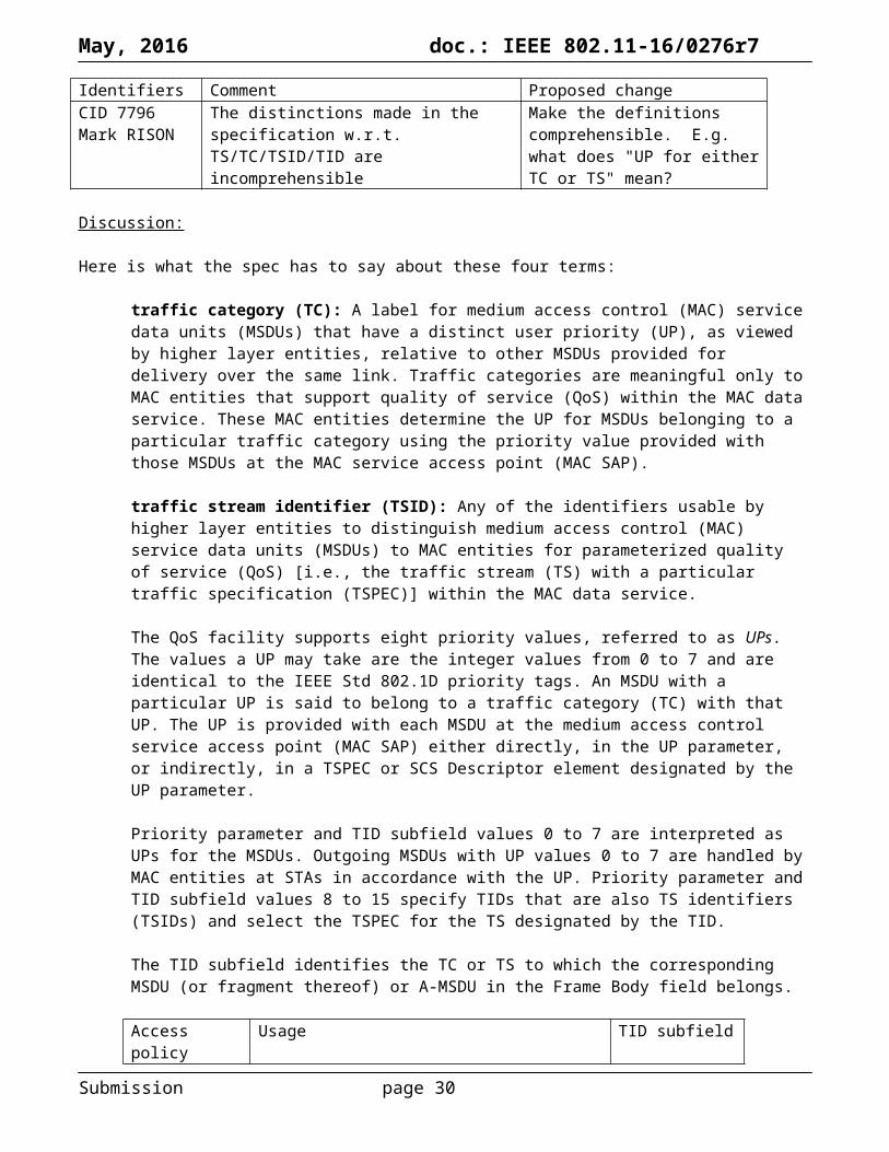
Identifiers Comment Proposed changeCID 7796Mark RISON
The distinctions made in the specification w.r.t. TS/TC/TSID/TID are incomprehensible
Make the definitions comprehensible. E.g. what does "UP for either TC or TS" mean?
Discussion:
Here is what the spec has to say about these four terms:
traffic category (TC): A label for medium access control (MAC) service data units (MSDUs) that have a distinct user priority (UP), as viewed by higher layer entities, relative to other MSDUs provided for delivery over the same link. Traffic categories are meaningful only to MAC entities that support quality of service (QoS) within the MAC data service. These MAC entities determine the UP for MSDUs belonging to a particular traffic category using the priority value provided with those MSDUs at the MAC service access point (MAC SAP).
traffic stream identifier (TSID): Any of the identifiers usable by higher layer entities to distinguish medium access control (MAC) service data units (MSDUs) to MAC entities for parameterized quality of service (QoS) [i.e., the traffic stream (TS) with a particular traffic specification (TSPEC)] within the MAC data service.
The QoS facility supports eight priority values, referred to as UPs. The values a UP may take are the integer values from 0 to 7 and are identical to the IEEE Std 802.1D priority tags. An MSDU with a particular UP is said to belong to a traffic category (TC) with that UP. The UP is provided with each MSDU at the medium access control service access point (MAC SAP) either directly, in the UP parameter, or indirectly, in a TSPEC or SCS Descriptor element designated by the UP parameter.
Priority parameter and TID subfield values 0 to 7 are interpreted as UPs for the MSDUs. Outgoing MSDUs with UP values 0 to 7 are handled by MAC entities at STAs in accordance with the UP. Priority parameter and TID subfield values 8 to 15 specify TIDs that are also TS identifiers (TSIDs) and select the TSPEC for the TS designated by the TID.
The TID subfield identifies the TC or TS to which the corresponding MSDU (or fragment thereof) or A-MSDU in the Frame Body field belongs.
Access policy Usage TID subfieldEDCA UP for either TC or TS,
regardless of whether admission control is required0-7
HCCA, SPCA TSID 8-15HEMM, SEMM TSID,
regardless of the access mechanism used8-15
The TID subfield contains the value of the TC or TS for which the BlockAck frame is being requested.
The TID subfield indicates the TSID or the UP for which the block ack has been originally set up.
The TSID subfield is 4 bits in length and contains a value that is a TSID. Note that the MSB (bit 4 in TS Info field) of the TSID subfield is always set to 1 when the TSPEC element is included within an ADDTS Response frame.
When present in the ADDTS Request frame, the Upper Layer Protocol Identification (U-PID) element indicates the upper layer protocol associated with the TID/TSID specified within the TSPEC element contained in this frame.
Submission page 24

May, 2016 doc.: IEEE 802.11-16/0276r7
When present in the ADDTS Response frame, the Upper Layer Protocol Identification (U-PID) element indicates the upper layer protocol associated with the TID/TSID specified within the TSPEC contained in this frame.
A QoS STA shall maintain a short retry counter and a long retry counter for each MSDU, A-MSDU, or MMPDU that belongs to a TC that requires acknowledgment.
The TID in the QoS Control fields of these frames shall indicate the TC or TS to which the MPDU belongs.
The AP may reallocate TXOPs if the request belongs to TS or update the EDCA parameter set if the above request belongs to TC.
The block ack record shall be updated irrespective of the acknowledgment type (Normal or Block Ack) for the TID/TSID with a block ack agreement.
Following a successful negotiation, a TS is created, identified within the non-AP STA by its TSID and direction, and identified within the HC by a combination of TSID, direction, and STA address.
Following a successful TS setup initiated by a non-AP STA, the TS becomes active, and either the non-AP STA or the HC may transmit QoS Data frames whose TID contains this TSID (according to the Direction field). In the case of EDCA, the TID contains the UP value.
When using transparent mode to transfer an FST session corresponding to a TID/TSID, the Direction subfield within the TSPEC element, if any, used to set up the TID/TSID should not be set to indicate a bidirectional link. This enables the SME to use the TID/TSID in conjunction with the source and destination MAC addresses in both the old and new frequency band/channel to uniquely identify the FST session.
The BlockAck is identified by the TID/TSID and MAC addresses of the Originator and the Recipient used in the band and channel indicated in the Multi-band element included in ADDBA Request and ADDBA Response frames.
What I think is:
A TS is a traffic stream A TSPEC is a definition of a traffic stream The UP is a number in the range 0-7 specifying a user priority The TC is a number also in the range 0-7 but identifying a user priority or a frame that is not part of a
defined traffic stream (not 100% sure how this differs from a UP, really) The TSID is a number in the range 8-15 identifying a defined traffic stream or a frame that is part of this
stream (but the frames in this stream are, in EDCA, identified over the air by the UP for that stream) The TID is a number in the range 0-15 that is a UP if it is <8 and is a TSID otherwise BA is set up and identified on a per-UP (not per-TSID) basis even for defined traffic streams (hm, so why
16 replay counters? Or maybe you can have BAs under HCCA/HEMM/SPCA/SEMM?)
Proposed changes:
Get the points in yellow resolved first.
Proposed resolution:
Submission page 25

May, 2016 doc.: IEEE 802.11-16/0276r7
Identifiers Comment Proposed changeCID 7202Mark RISON9.4.2.1671065.16
11.24.6.4 only requires that "Within a burst instance, consecutive Fine Timing Measurement frames shall be spaced at leastMin Delta FTM apart." However, the cited location suggests it also applies to FTM frames in different bursts or not in a burst
Change "The Min Delta FTM field indicates the minimum time between consecutive Fine Timing Measurement frames." to "The Min Delta FTM field indicates the minimum time between consecutive Fine Timing Measurement frames in a burst instance."
Discussion:
It is preferable to make Min Delta FTM apply to all FTM frames, including the first FTM frame in a non-ASAP FTM session (which is not in a burst instance) and the frames at the end of one burst instance and the start of the next, as this ensures the initiating STA will not be overloaded.
Proposed resolution:
REVISED
At 1768.30 change “Within a burst instance, consecutive Fine Timing Measurement frames shall be spaced at least Min Delta FTM apart.” to “Consecutive Fine Timing Measurement frames transmitted to a given peer STA shall be spaced at least Min Delta FTM apart.”
Submission page 26

May, 2016 doc.: IEEE 802.11-16/0276r7
Identifiers Comment Proposed changeCID 7468Mark RISON9.4.2.1671066.30
"The FTM Format And Bandwidth field indicates the requested or allocated packet format and bandwidth used by all Fine Timing Measurement frames in an FTM session" -- this is not true, since FTM frames can use a simpler or narrower format than indicated.
Change to "The FTM Format And Bandwidth field indicates the requested or allocated PPDU format and bandwidth that can be used by Fine Timing Measurement frames in an FTM session"
Proposed resolution:
ACCEPTED
Submission page 27

May, 2016 doc.: IEEE 802.11-16/0276r7
Identifiers Comment Proposed changeCID 7504Mark RISON11.24.61764.23
There should be a mechanism to allow the responding STA to ask the initiating STA to re-initiate an FTM session (because it wants to change the parameters)
As it says in the comment. A bit in the FTM frame could be used to signal this
Proposed resolution:
REJECTED
Such a mechanism is not necessary. If the responding STA wishes to change the parameters, it can terminate the FTM session using an FTM frame with the Dialog Token set to 0, and if the initiating STA wishes to continue doing FTM it will send an FTM Request frame to start a new FTM session, allowing the responding STA to specify new parameters.
Submission page 28

May, 2016 doc.: IEEE 802.11-16/0276r7
Identifiers Comment Proposed changeCID 7419Mark RISON
10.8 says "For MSDUs or A-MSDUs belonging to the service class of QoSAck when the receiver is a QoS STA, the QoS Data frames that are used to send these MSDUs or A-MSDUs shall have the Ack Policy subfield in the QoS Control field set to Normal Ack, Block Ack, Implicit Block Ack Request, or PSMP Ack." But 5.1.1.4 says "When an MSDU is received from the MAC SAP with [QoSAck] and the recipient STA is a QoS STA [...] the MSDU is transmitted using a QoS Data frame with the Ack Policy subfield in the QoS Control field set to either Normal Ack (normal acknowledgment) or Block Ack."
Work out which is right and make the other one say the same. Even better, avoid the duplication
Discussion:
Subclause 10.8 MSDU transmission restrictions says (reformatted for clarity; my emphasis):
For MSDUs or A-MSDUs belonging to the service class of QoSAck when the receiver is a QoS STA, the QoS Data frames that are used to send these MSDUs or A-MSDUs shall have the Ack Policy subfield in the QoS Control field set to Normal Ack, Block Ack, Implicit Block Ack Request, or PSMP Ack.
For MSDUs or A-MSDUs belonging to the service class of QoSNoAck when the receiver is a QoS STA, the QoS Data frames that are used to send these MSDUs or A-MSDUs shall have the Ack Policy subfield in the QoS Control field set to No Ack.
Subclause 5.1.1.4 Interpretation of service class parameter in MAC service primitives in a STA says (ditto):
When an MSDU is received from the MAC SAP with one of the following service class indications, and the recipient STA is a QoS STA:
— QoSAck, the MSDU is transmitted using a QoS Data frame with the Ack Policy subfield in the QoSControl field set to either Normal Ack (normal acknowledgment) or Block Ack.
— QoSNoAck, the MSDU is transmitted using a QoS Data frame with the Ack Policy subfield in theQoS Control field set to No Ack (no acknowledgment).
Oh, and Subclause 9.2.4.5.4 Ack Policy subfield says (ditto):
An MSDU is sent in a QoS Data frame with the Ack Policy subfield
set to Normal Ack, Implicit Block Ack Request, PSMP Ack or Block Ack if the service class parameter in the MA-UNITDATA.request primitive is QoSAck and
set to No Ack if the service class parameter in the MA-UNITDATA.request primitive is equal to QoSNoAck.
So it’s not duplicated, it’s triplicated. And one of the copies does not agree with the other two. And that copy assumes the MSDU fits in an MPDU; it doesn’t consider the possibility that it might be fragmented.
The last copy seems to be behaviour and as such shouldn’t be in Clause 9.
Submission page 29
May, 2016 doc.: IEEE 802.11-16/0276r7
I would argue that we should also delete the 5.1.1.4 text, but the other Mark disagrees, opining that “Clause 5 is supposed to describe the SAP, and how the SAP parameters are mapped to behaviors inside the MAC.”
Proposed changes:
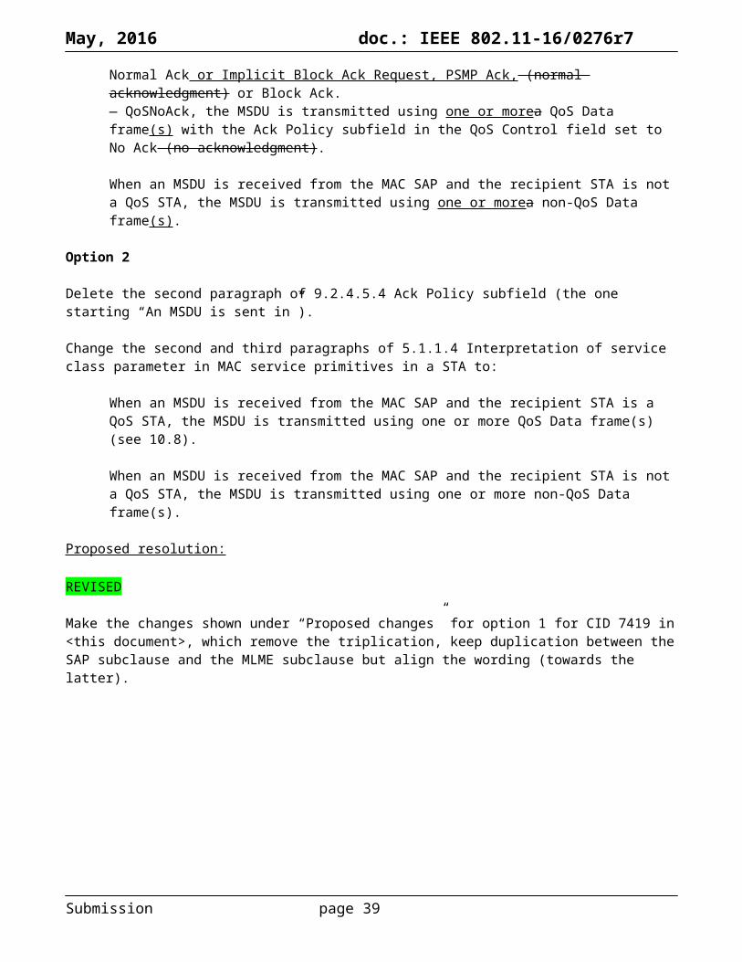
Option 1
Delete the second paragraph of 9.2.4.5.4 Ack Policy subfield (the one starting “An MSDU is sent in”).
Change the second and third paragraphs of 5.1.1.4 Interpretation of service class parameter in MAC service primitives in a STA as follows:
When an MSDU is received from the MAC SAP with one of the following service class indications, and the recipient STA is a QoS STA:— QoSAck, the MSDU is transmitted using one or morea QoS Data frame(s) with the Ack Policy subfield in the QoS Control field set to either Normal Ack or Implicit Block Ack Request, PSMP Ack, (normal acknowledgment) or Block Ack.— QoSNoAck, the MSDU is transmitted using one or morea QoS Data frame(s) with the Ack Policy subfield in the QoS Control field set to No Ack (no acknowledgment).
When an MSDU is received from the MAC SAP and the recipient STA is not a QoS STA, the MSDU is transmitted using one or morea non-QoS Data frame(s).
Option 2
Delete the second paragraph of 9.2.4.5.4 Ack Policy subfield (the one starting “An MSDU is sent in”).
Change the second and third paragraphs of 5.1.1.4 Interpretation of service class parameter in MAC service primitives in a STA to:
When an MSDU is received from the MAC SAP and the recipient STA is a QoS STA, the MSDU is transmitted using one or more QoS Data frame(s) (see 10.8).
When an MSDU is received from the MAC SAP and the recipient STA is not a QoS STA, the MSDU is transmitted using one or more non-QoS Data frame(s).
Proposed resolution:
REVISED
Make the changes shown under “Proposed changes” for option 1 for CID 7419 in <this document>, which remove the triplication, keep duplication between the SAP subclause and the MLME subclause but align the wording (towards the latter).
Submission page 30

May, 2016 doc.: IEEE 802.11-16/0276r7
Identifiers Comment Proposed changeCID 7320Mark RISON9.2.2564.1
Like ASCII strings, UTF-8 strings should not be terminated
Add "or UTF-8" after "ASCII"
CID 7499Mark RISON8.3.4.4549.25
"At most 4 bits out of 8 may be set to 1." for ACTIVE_RXCHAIN_SET - does this mean that a VHT STA with > 4 receive chains can't use SMPS (because a STA with SMPS is required to enable all rx chains when not in SMPS mode)?
Delete this restriction
CID 7532Mark RISON11.421880.47
"A STA that is not a VHT STA shall setdot11OperatingModeNotificationImplemented to false." -- there is no justification for this. Why can't an HT non-VHT STA do OMN?
Delete this sentence
CID 7549Mark RISON9.6.8.161146.29
The TDLS Discovery Response frame format (which is the only TDLS frame which is not tunnelled in a Data frame) does not have space for VSIEs. Note this is not the usual thing where you have an Action field being described, where the Action frame containing the Action field can have some VSIEs after it
Allow for VSIEs at the end of the frame
CID 7746Mark RISON10.3.71297.34
" provided that the CCAsensitivity specification for the attached PHY is met (see 15.4.6.5 (CCA), 16.3.8.5 (CCA), 17.3.10.6 (CCArequirements), 18.4.6 (CCA performance) and 19.3.19.5 (CCA sensitivity))." -- what about Clauses 20 and 21 and 22?
Add references to the CCA bit of these. Or just delete the parenthesis
CID 7795Mark RISON
"A STA shall support the concurrent reception of fragments of at least three MSDUs or MMPDUs." -- frankly, this is not good enough nowadays, even for non-AP STAs (consider QoS, for example)
Add "A STA should support the concurrent reception of fragments of at least one MSDU per access category. An AP should support the concurrent reception of at least on MSDU per access category per associated STA."
Discussion:
564.1: “ASCII strings are not null terminated.”
549.21:
Submission page 31

May, 2016 doc.: IEEE 802.11-16/0276r7
1146.1:
1308.44:
Proposed resolution:
ACCEPTED
Submission page 32

May, 2016 doc.: IEEE 802.11-16/0276r7
Identifiers Comment Proposed changeCID 7608Mark RISON6.5.4.2534.55
"The relationship between aMACProcessingTime and the IFS and slot timing is described in 9.3.7 (DCF timing relations) and illustrated in Figure 9-19 (DCF timing relationships)." -- needs to be extended to EDCA
Add references to the EDCAF timing relations subclause and figure
Discussion:
There is no subclause discussing the relationship between aMACProcessingDelay and the IFS/slot timing for EDCA, but there is a figure equivalent to Figure 10-19, namely Figure 10-26 in 10.22.2.4. The IFS and slot timings are defined by Subclause 10.3.7 even for EDCA. This is not always referenced, though. The approach taken below is to stick to 10.3.7 for the IFS/slot duration definitions, but to refer to 10.22.2.4/F10-26 for slot boundaries and behaviour under EDCA.
Proposed resolution:
REVISED
Change the cited sentence to “See 10.3.7 (DCF timing relations).”
At the end of the first para of 10.3.7 add “The IFSs apply to transmission under EDCA too. (See Figure 10-26.)”.
In Figure 10-190 change “SIFS” to “aSIFSTime” and “Slot time” to “aSlotTime” (4x).
In Figure 10-26 add a “PHY-RXEND.indication” after the first D1 (as in Figure 10-10), prepend “PIFS, or” tochange “AIFS for AIFSN = 1” to “PIFS” and prepend “TxPIFS and” tochange “AIFSN = 1 slot boundary” to “TxPIFS slot boundary”.
At the end of the last para of 8.3.5.5.4, 8.3.5.14.3 add “and Figure 10-26”.
At the end of the first sentence in 8.3.5.14.4, third para of 10.3.2.3.3, last para of 10.3.2.3.4 add “and 10.22.2.4”.
Change the first sentence of 10.21.6 to “The attribute aSlotTime and other MAC timings are based on the PHY timing parameters, as specified in 10.3.2.3 (IFS), 10.3.7 (DCF timing relations) and 10.22.2.5, and in particular on aAirPropagationTime.”.
At 1356.44, 1404.45, 1424.33, 1427.55, 1604.1 change “the TxPIFS slot boundary (defined in 10.3.7 (DCF timing relations))” to “the TxPIFS slot boundary (see Figure 10-26)”.
At 1363.50 change “the TxPIFS slot boundary as defined in 10.3.7 (DCF timing relations)” to “the TxPIFS slot boundary (see Figure 10-26)”.
At 1364.21 change “the TxPIFS slot boundary after the TXOP as defined in 10.3.7 (DCF timing relations)” to “the TxPIFS slot boundary after the TXOP (see Figure 10-26).”. Note the addition of the missing full stop.
At 1730.36 change “slot boundaries (defined in 10.3.7 (DCF timing relations))” to “slot boundaries (see Figure 10-26)”.
At 1730.41 change “defined in 10.3.7” to “defined in 10.22.2.4”.
At 2229.37 and 2259.35 change “Refer to Figure 10-19 (DCF timing relationships) (in 10.3.7 (DCF timing relations)) for a definition of slot time boundary.” to “Refer to Figure 10-19 (DCF timing relationships) (in 10.3.7 (DCF timing relations)) and Figure 10-26 for a definition of slot boundaries.”
Submission page 33

May, 2016 doc.: IEEE 802.11-16/0276r7
Proposed resolution:
REVISED
Make the changes shown under “Proposed changes” for CID 7608 in <this document>, which effect the requested changes.
Submission page 34

May, 2016 doc.: IEEE 802.11-16/0276r7
Identifiers Comment Proposed changeCID 7427Mark RISON11.23.11740.44
"A DMG STA shall not use the TDLS protocol." -- may it use DLS?
Change to "A DMG STA shall not use the DLS or TDLS protocols."
Discussion:
No, it may not. See 11.7 DLS operation, 11.7.1 General: “Since the channel access in a DMG BSS allows DMG STAs to send frames directly to each other, a DMG STA shall not use the DLS protocol.” But it’s not clear why an excuse is needed (there’s no excuse for TDLS).
Proposed resolution:
REVISED
At 1658.41 change “Since the channel access in a DMG BSS allows DMG STAs to send frames directly to each other, a DMG STA shall not use the DLS protocol.” to “A DMG STA shall not use the DLS protocol.”
Submission page 35

May, 2016 doc.: IEEE 802.11-16/0276r7
Identifiers Comment Proposed changeCID 7529Mark RISON9.3.3.15647.8
There is no reason Action No Acks can't have MICEs. While at the moment it may be the case that such frames carry "information [...] that is of time critical but transient value" (resolution of CID 6343), this is not a property of Action No Acks per se
Add MICEs to Table 9-39 as in Table 9-38
Discussion:
Submission page 36

May, 2016 doc.: IEEE 802.11-16/0276r7
There are ~70 instances of “Action No Ack”. None of them indicate that Action No Acks are only for “information [...] that is of time critical but transient value”. Indeed, to the contrary, 9.6.20.5 Information Response frame format indicates that an Information Response frame (which has a category of DMG, which per Table 9-47 does not receive privacy) may be broadcast in an Action No Ack.
However, 12.2.8 defines “robust Management frames” as “Disassociation, Deauthentication, and robust Action frames”, and a 3.2 defines “robust Action frame” as “An Action frame with a category value specified in 9.4.1.11 (Action field) Table 9-47 (Category values) with “Yes” in the “Robust” column”. Note that this is specific to Action frames, which do not include Action No Ack frames (9.3.3.15: “Unless specified as allowing the use of the Action No Ack management frame subtype, a frame described as an “Action frame” uses only the Action subtype.”).
The frames that can be sent as Action No Ack frames are:9.6.7.4 Link Measurement Request [when in a DMG BSS only; then not robust per NOTE 1 in T9-47]9.6.7.5 Link Measurement Report [when in a DMG BSS only; then not robust per NOTE 1 in T9-47]9.6.12.6 CSI [HT; not robust]9.6.12.7 Noncompressed Beamforming [HT; not robust]9.6.12.8 Compressed Beamforming [HT; not robust]9.6.12.9 Antenna Selection Indices Feedback [HT; not robust]9.6.20.5 Information Response [DMG; when broadcast; robust]9.6.22.2 Announce [DMG; robust]9.6.22.3 BRP [VHT; not robust]9.6.23.2 VHT Compressed Beamforming [VHT; not robust]
So the only ones which are robust are the DMG ones, and DMG does not “receive (group-addressed) privacy”. All the others are not robust so would not get an MME anyway.
What we should do is, for the future (won’t someone please think of the children?) to put Action No Acks on a par with Actions, with an exception for DMG. For DMG there would be value, but existing implementations would not include it (though by definition they would not have trouble if it were present), so an exception is needed.
Proposed changes:
Add a definition in 3.2:
Submission page 37

May, 2016 doc.: IEEE 802.11-16/0276r7
robust Action No Ack frame: An Action No Ack frame with a category value specified in 9.4.1.11 (Action field) Table 9-47 (Category values) with “Yes” in the “Robust” column
Change 12.2.8’s first sentence as follows:
The robust Management frames are Disassociation, Deauthentication, robust Action and robust Action No Ack frames.
Change Table 9-39—Action No Ack frame body to:
Order Information
1 Action
Last – 1 One or more vendor-specific elements are optionally present.
Last The Management MIC element (MME) is present when management frame protection is enabled at the AP, the frame is a group addressed robust Action No Ack frame, the category of the Action No Ack frame is not DMG, and the category does not receive privacy as indicated by Table 9-47 (Category values).The Management MIC element (MME) is optionally present when management frame protection is enabled at the AP, the frame is a group addressed robust Action No Ack frame, and the category of the Action No Ack frame is DMG.
Change the first two paras of 9.6.20.5 as follows:
The Information Response frame is an Action or Action No Ack frame of category DMG. The format of an Information Response frame Action field is shown in Table 9-386 (Information Response frame Action field format).
This frame is individually addressed to a STA in response to an Information Request frame or it is sent unsolicited and individually addressed to a STA or broadcast to all STAs in the PBSS/infrastructure BSS. If this frame is sent as a broadcast, then this frame is an Action No Ack frame, otherwise it is an Action frame.
Proposed resolution:
REVISED
Make the changes shown under “Proposed changes” for CID 7529 in <this document>, which effect the requested change.
Note to the commenter: the information in Information Response frames is not “information [...] that is of time critical but transient value”.
Submission page 38
May, 2016 doc.: IEEE 802.11-16/0276r7
Identifiers Comment Proposed changeCID 7349Mark RISON
It was stated during D4.0 comment resolution (*cough*Adrian*cough*) that "transmission of the Beacon at TBTT is a famously individual and unnamed channel access function"
Add a subclause on this CAF
Discussion:
The current rules on beacon generation make no mention of any special channel access function. However, it is desirable, on power-saving grounds, for beacons to take precedence over other transmissions.
There are very specific rules for beacons in IBSSen (11.1.3.5) and in DMG BSSen (11.1.3.3 and 11.1.3.4). It is only for non-DMG infrastructure BSSen and MBSSen that the rules are vague.
Proposed changes:
Change the first para of 11.1.3.2 Beacon generation in non-DMG infrastructure networks as follows:
The AP shall define the timing for the entire BSS by transmitting Beacon frames according to dot11BeaconPeriod. This defines a series of TBTTs exactly dot11BeaconPeriod TUs apart. Time 0 is defined to be a TBTT with the Beacon frame being a DTIM. At each TBTT, the AP shall schedule a Beacon frame as the next frame for transmission by. At each TBTT the AP should suspending the transmission of decrementing of the backoff timer for any pending non-Bbeacon framestransmission, and transmitting the Beacon frame when the DCF backoff timer or an EDCAF backoff timer reaches 0 (according to the medium access rules specified in Clause 10 (MAC sublayer functional description)) and then unsuspending the transmission of any pending non-Beacon frames. The beacon period is included in Beacon and Probe Response frames, and a STA shall adopt that beacon period when joining the BSS, i.e., the STA sets dot11BeaconPeriod to that beacon period.
Change the second para of 14.13.3.1 Beacon generation in MBSSs as follows:
The mesh STA shall define a series of TBTTs exactly dot11BeaconPeriod TUs apart. Time zero is defined to be a TBTT with the Beacon frame containing a DTIM. At each TBTT, the mesh STA shall schedule a Beacon frame as the next frame for transmission by suspending the transmission of any pending non-Beacon frames, transmitting the Beacon frame when an EDCAF backoff timer reaches 0 (according to the medium access rules specified in Clause 10 (MAC sublayer functional description)) and then unsuspending the transmission of any pending non-Beacon frames. The beacon period is included in Beacon and Probe Response frames.
Alternative option (with similar tweaks for MBSS):
Change the first para of 11.1.3.2 Beacon generation in non-DMG infrastructure networks as follows:
The AP shall define the timing for the entire BSS by transmitting Beacon frames according to dot11BeaconPeriod. This defines a series of TBTTs exactly dot11BeaconPeriod TUs apart. Time 0 is defined to be a TBTT with the Beacon frame being a DTIM. At each TBTT, the AP shall schedule a Beacon frame as the next frame for transmission. At each TBTT the AP should suspend the decrementing of the backoff timer for any pending non-beacon transmission and transmit the Beacon frame according to the medium access rules specified in Clause 10 (MAC sublayer functional description).NOTE—The AP might do so by transmitting the Beacon frame ahead of any other queued frame, when the DCF next seizes or any EDCAF next seizes the medium. The beacon period is included in Beacon and Probe Response frames, and a STA shall adopt that beacon period when joining the BSS, i.e., the STA sets dot11BeaconPeriod to that beacon period.
Submission page 39

May, 2016 doc.: IEEE 802.11-16/0276r7
Proposed resolution:
REVISED
Make the changes shown under “Proposed changes” for CID 7349 in <this document>, which clarify the CAF for non-DMG infrastructure BSSen and MBSSen.
Submission page 40

May, 2016 doc.: IEEE 802.11-16/0276r7
Identifiers Comment Proposed changeCID 7429Mark RISON11.2.2.5.21579.25
"The non-AP STA may transmit multiple ADDTS Request frames to the AP where the last received ADDTS Request frame will override any previously received ADDTS Request frame." -- this seems too general: it only applies if the TID/direction are the same. Any anyway, what is this doing in 11.2.2.5.2 U-APSD coexistence
Confirm the specific rules for one ADDTS Req overriding an earlier one are covered elsewhere, then delete this sentence
Discussion:
No, they are not covered elsewhere! Oops!
Proposed changes:
At the referenced location delete the cited sentence.
Change the para of 11.4.3 TS life cycle at 1637.21 as follows:
While the TS is active, the non-AP STA can attempt to renegotiate the parameters of the TSPEC characterizing the TS or the parameters of the DMG TSPEC characterizing the allocation carrying the TS can be renegotiated, when the renegotiation is initiated by the non-AP STA. This negotiation might succeed, resulting in a change to the TSPEC or DMG TSPEC, or might fail, resulting in no change to the TSPEC or DMG TSPEC.
Change the first para of 11.4.4.4 TS setup procedures for both AP and non-AP STA initiation as follows:
The non-AP STA’s SME decides that a TS needs to be created. How it does this, and how it selects the TSPEC or DMG TSPEC parameters, is beyond the scope of this standard. The SME generates an MLME-ADDTS.request primitive containing a TSPEC or DMG TSPEC. A TSPEC or DMG TSPEC may also be generated autonomously by the MAC without any initiation by the SME. However, if a TSPEC or DMG TSPEC is generated subsequently by the SME and the responding MLME-ADDTS.confirm primitive contains ResultCode=SUCCESS, the TSPEC or DMG TSPEC containing the same TSID generated autonomously by the MAC shall be overridden. If one or more TSPECs or DMG TSPECs are initiated by the SME, the autonomous TSPEC or DMG TSPEC shall be terminated.NOTE—Such a TSPEC or DMG TSPEC might be overridden as a result of a subsequent MLME-ADDTS.request primitive from the SME (see 11.4.4.4b).
Change the paras of 11.4.4.4 TS setup procedures for both AP and non-AP STA initiation at 1641.35 as follows:
The parameters that are set for a TS may be renegotiated in a similar manner (see 11.4.4.b), when such a request is generated by the SME through ADDTS.request primitive. When a request for the modification of the TS parameters is accepted by the HC, it shall reset both the suspension interval and the inactivity interval timers.
When a request for the modification of the TS parameters is accepted by a non-AP STA, it shall reset the inactivity interval timers.
Insert a new subclause 11.4.4.4b TS renegotiation as follows:
A non-AP STA may attempt to modify the parameters of a TSPEC or DMG TSPEC by transmitting an ADDTS Request or DMG ADDTS Request frame. If the Status Code in the corresponding ADDTS Response or DMG ADDTS Response frame is SUCCESS, then any TSPEC with the same TSID or DMG
Submission page 41

May, 2016 doc.: IEEE 802.11-16/0276r7
TSPEC with the same allocation ID is overridden with the TSPEC or DMG TSPEC in that frame, the HC and non-AP STA shall reset the inactivity interval timer, and the HC shall reset the suspension interval timer.
Change the second para of K.4 TSPEC construction as follows:
Note that a TSPEC can also be generated autonomously by the MAC without any initiation by the SME. However, if a TSPEC is generated subsequently by the SME, the TSPEC generated autonomously by the MAC ismight be overridden (see 11.4.4.4b). If one or more TSPECs are initiated by the SME, the autonomous TSPEC, containing the same TSID is terminated.
At 1577.13 change “overwrites” to “overrides”.
At 848.61 change “TID” to “TSID”.
Proposed resolution:
REVISED
Make the changes shown under “Proposed changes” for CID 7429 in <this document>, which make the rules for TSPEC overriding clear.
Submission page 42
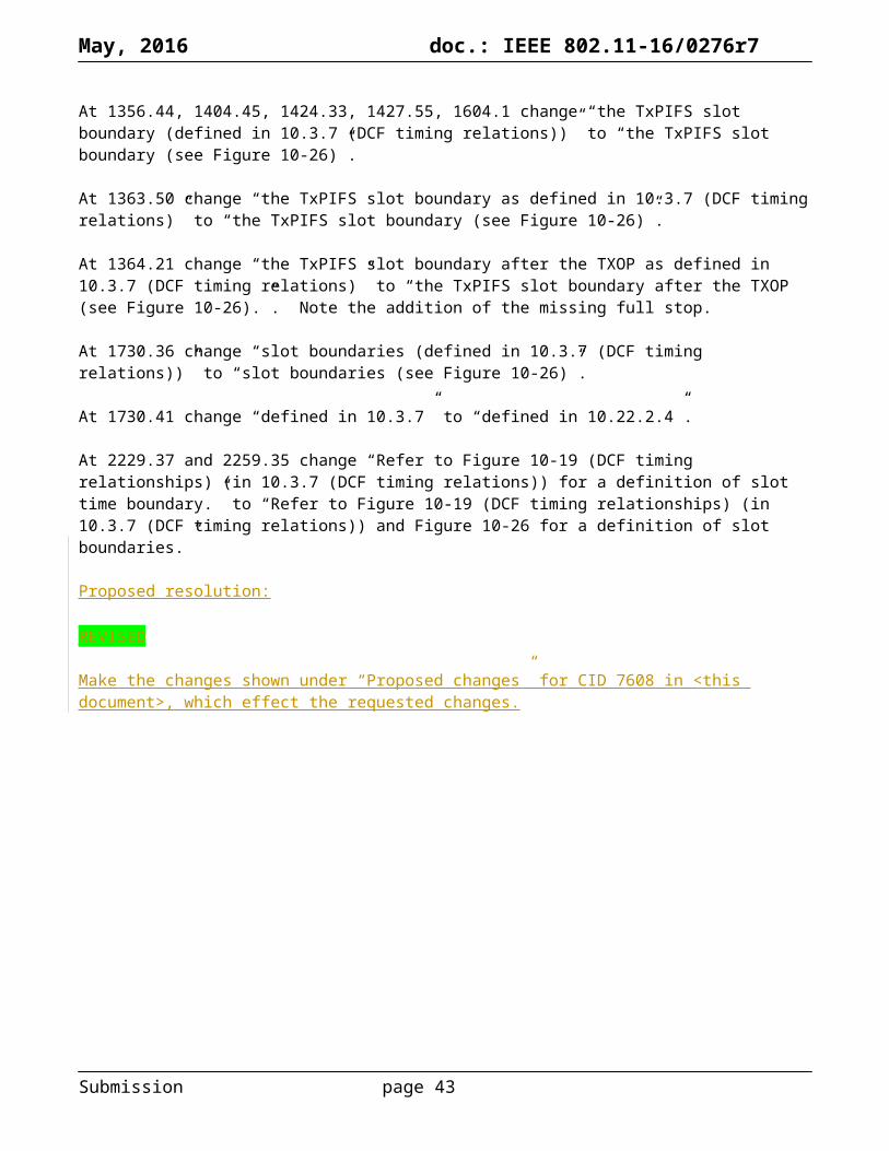
May, 2016 doc.: IEEE 802.11-16/0276r7
Identifiers Comment Proposed changeCID 7347Mark RISON9.4.2.25828.35
A, uh, popular implementation of the RSN protocol cannot cope with RSNE counts that are zero (it does *not* skip over them and just use the defaults)
In 9.4.2.25.2 after "The Pairwise Cipher Suite Count field indicates the number of pairwise cipher suite selectors that are contained in the Pairwise Cipher Suite List field." add "The value 0 is reserved."In 9.4.2.25.3 after "The AKM Suite Count field indicates the number of AKM suite selectors that are contained in the AKM Suite List field." add "The value 0 is reserved."In 9.4.2.25.5 change "The PMKID Count specifies the number of PMKIDs in the PMKID List field. The PMKID list contains 0 or more PMKIDs" to "The PMKID Count field specifies the number of PMKIDs in the PMKID List field. The value 0 is reserved. The PMKID List field contains PMKIDs"
Discussion:
“[…] The RSNE contains up to and including theVersion field. All fields after the Version field are optional. If any nonzero length field is absent, then noneof the subsequent fields is included.”
So, naively, I would have assumed that you could put 0 in the Parwise Cipher Suite Count octets and then continue with the rest of the RSNE, viz. the AKM Suite Count field, relying on the default pairwise cipher (CCMP-128 for non-DMG, GCMP-128 for DMG), and ditto for the AKM Suite Count field. However, it seems at least one widespread implementation will break if you do this. However, apparently it does cope 0 in the PMKID Count octets.
Proposed resolution:
REVISED
In 9.4.2.25.2 at 830.17 after "The Pairwise Cipher Suite Count field indicates the number of pairwise cipher suite selectors that are contained in the Pairwise Cipher Suite List field." add "The value 0 is reserved."
In 9.4.2.25.3 at 832.32 after "The AKM Suite Count field indicates the number of AKM suite selectors that are contained in the AKM Suite List field." add "The value 0 is reserved."
Submission page 43

May, 2016 doc.: IEEE 802.11-16/0276r7
In 9.4.2.25.5 change "The PMKID Count specifies the number of PMKIDs in the PMKID List field. The PMKID list contains 0 or more PMKIDs" to "The PMKID Count field indicates the number of PMKIDs that are contained in the PMKID List field. The PMKID List field contains a series (possibly empty) of PMKIDs"
Note to the commenter: PMKID Count 0 is required if PMKSA caching is not used but PMF is used. It’s only the pairwise cipher and AKM suite counts that can’t be 0.
Submission page 44

May, 2016 doc.: IEEE 802.11-16/0276r7
Identifiers Comment Proposed changeCID 7376Mark RISON12.5.3.3.61949.26
"A transmitter shall not use IEEE Std 802.11 MSDU or A-MSDU priorities without ensuring that the receiver supports the required number of replay counters." is not clear. It mixes indices (priorities) with a count (#rc)
Reword as something like "A transmitter shall not use an IEEE Std 802.11 MSDU or A-MSDU priority if this would cause the total number of priorities used during the lifetime of the SA to exceed the number of replay counters supported by the receiver for that SA."
Discussion:
As the comment says. Additionally, it has been pointed out that “the receiver” is not appropriate for group SAs.
Proposed resolution:
REVISED
Change the cited sentence to “A transmitter shall not use an IEEE Std 802.11 MSDU or A-MSDU priority if this would cause the total number of priorities used during the lifetime of the SA to exceed the number of replay counters supported by the receiver (for a pairwise SA) or all the receivers (for a group SA) for that SA.”.
Submission page 45

May, 2016 doc.: IEEE 802.11-16/0276r7
Identifiers Comment Proposed changeCID 7527Mark RISON
"GTK key", "PSK key identifier", "IGTK key", "TPK key", "PTK Key Holder", "PTK key", "PMK key", "SMK key", "SKCK key", "STK Key" all suffer from RAS syndrome.
Delete "key" (case-insensitively) in all such instances
Discussion:
OK, except that “FooK key holder” is not to be understood as “holder for foo key key” but as “key holder for foo key”. Similarly for “IGTK key data encapsulation (KDE)”.
Proposed resolution:
REVISED
Change “PMK key” to “PMK” at 2007.4.
Change “PSK key” to “PSK” at 126.47, 126.49 (but see also the resolution to CID 7378).
Change “PTK key” to “PTK” at 1996.54, 2072.48, 2073.1, 2075.2, 2086.45.
Change “PTK Key request” to “PTK rekey request” at 2097.48.
Change “PTK keys” to “PTK” at 2102.35.
Change “GTK keys” to “GTK and, if management frame protection is negotiated, the IGTK” at 120.18.
Change “IGTK key” to “IGTK” at 1954.1, 2050.25.
Change “TPK key” to “TPK” at 1984.63.
Change “TPK Key Lifetime” to “TPK key lifetime” at 1145.57 (2x), 1174.51 (2x), 1176.35 (2x), 1177.57 (2x).
Change “SMK key” to “SMK” at 2007.5.
Change “STK Key” to “STK” at 2040.53.
Change “STK keys” to “STKs” at 2937.30.
Change “using SKCK key” to “using the SKCK” at 2011.2, 2013.40.
Note to the commenter: “FooK key holder” is not to be understood as “holder for foo key key” but as “key holder for foo key”. Similarly for “IGTK key data encapsulation (KDE)” and “TPK key lifetime”.
Submission page 46

May, 2016 doc.: IEEE 802.11-16/0276r7
Identifiers Comment Proposed changeCID 7484Mark RISON10.22.2.21348.59
The rules for "successful transmission and transmission failure" for the purposes of EDCA backoff are made harder to follow because terms are not used consistently:: "If $blah, the STA concludes that the transmission of the MPDU has failed." and then "$foo shall be interpreted as failure of the MPDU transmission." and then "$bar is defined to be a failure." They should all be of the same form (e.g. "shall be considered transmission failure")
In this subclause, always use "MPDU", not "frame", and express the rules in the same way (so e.g. not "the STA concludes that the transmission of the MPDU has failed" and then "The recognition of a valid response frame [...] shall be interpreted as a successful response.")
Discussion:
The page reference is off by one.
Proposed changes:
Change from 1349.59 as follows (note additional bullet breaks and indentation):
For the purposes of this subclause, transmission failure of an MPDU is defined as follows:
— After transmitting an MPDU (even if it is carried in an A-MPDU or as part of a VHT MU PPDU that might haveis sent using TXVECTOR parameter NUM_USERS > 1) that requires an immediate frame as a response:
, t—The STA shall wait for a timeout interval of duration of aSIFSTime + aSlotTime + aRxPHYStartDelay, starting when the MAC receives a PHY-TXEND.confirm primitive. If a PHY- RXSTART.indication primitive does not occur during the timeout interval, the STA concludes that the transmission of the MPDU has failed.
— If a PHY-RXSTART.indication primitive does occur during the timeout interval, the STA shall wait for the corresponding PHY-RXEND.indication primitive to recognize a valid response MDPDU that either does not have a TA field or is sent by the recipient of the MPDU requiring a response. The recognition of If anything else, including any other valid frame, shall be interpreted as failure of the MPDU transmission is recognized, the transmission of the MPDU has failed.
— The nonfinal (re)transmission of an MPDU that is delivered using the GCR unsolicited retry retransmission policy (10.22.2.10.2 (Unsolicited retry procedure))) is defined to be a failure.
In all other cases, the transmission of the MPDU has not failed.
At 1350.24 change “c) The expected immediate response to the initial MDPU of a TXOP of that AC is not received and the AC was a primary AC.” to “c) The transmission of an MPDU in the initial PPDU of a TXOP fails, as defined in this subclause, and the AC was a primary AC.”
At 1350.35 change as follows:
In addition, the backoff procedure may be invoked forby an EDCAF when:
f) tThe transmission by the TXOP holder of thean MPDUs in a noninitial PPDU of a TXOP by the TXOP holder fails, as defined in this subclause.”
Submission page 47

May, 2016 doc.: IEEE 802.11-16/0276r7
At 1350.49 change “because of reason” to “for reason”.
At 1350.51 change “If the backoff procedure is invoked because of a failure event [reason c), d), or e) above or the transmission failure of a non-initial frame by the TXOP holder],” to “If the backoff procedure is invoked for reason c), d), e) or f) above,”.
Proposed resolution:
REVISED
Make the changes shown under “Proposed changes” for CID 7484 in <this document>, which effect the requested changes.
Submission page 48
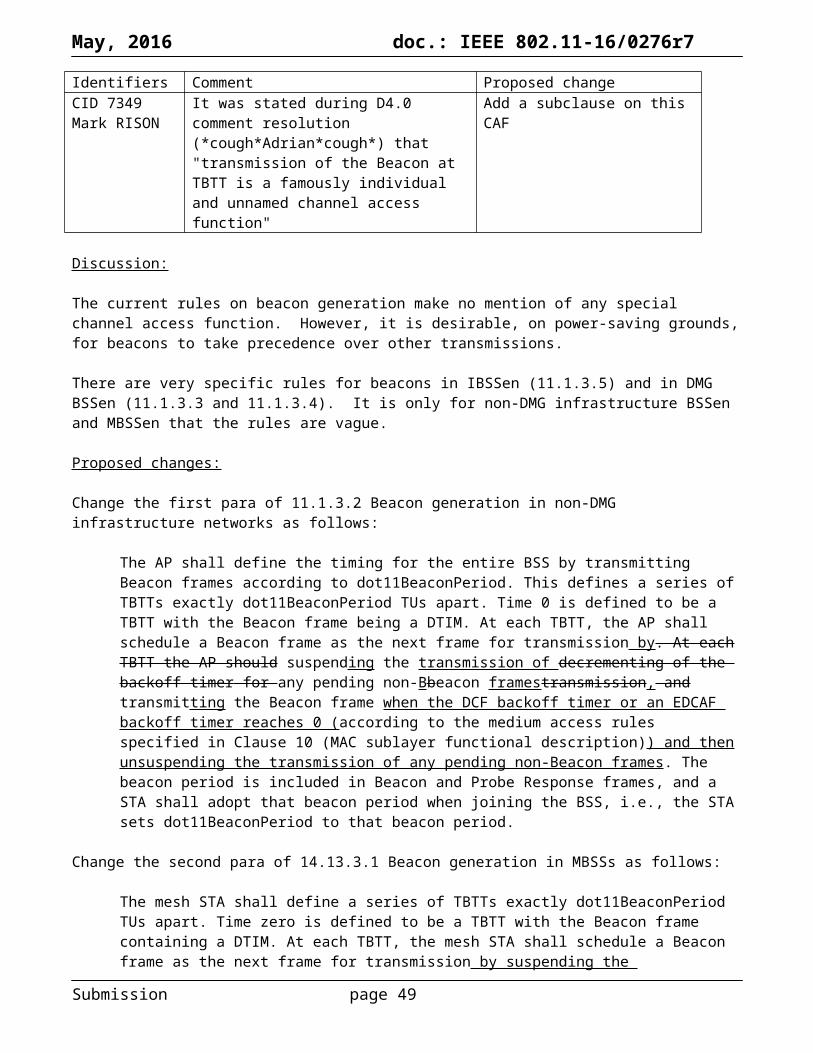
May, 2016 doc.: IEEE 802.11-16/0276r7
Identifiers Comment Proposed changeCID 7674Mark RISON9.4.1.53715.29
It says "The use of these fields is described in 10.7.12.1 (Rx Supported VHT-MCS andNSS Set), 10.7.12.2 (Tx Supported VHT-MCS and NSS Set), and 10.40.8(Extended NSS BW Support Signaling). For a VHT STA, see Table 9-74(Setting of the Channel Width subfield and Dynamic Extended NSS BWsubfield at a VHT STA transmitting the Operating Mode field). " but the new Rx NSS text has no references to Clauses 9 or 10, but does have a reference to elsewhere in Clause 8. This seems inconsistent
Either refer to Clauses 8 and 9/10 everywhere or nowhere
Discussion:
There are references to both Clauses 9 and 10 in the text (note the commenter got the clause numbers all jumbled up due to the renumbering).
Dynamic ExtendedNSS BW
The Dynamic Extended NSS BW field, combined with the Channel Width field, Supported Channel Width Set field and the Supported VHT-MCS and NSS Set field indicates whether 80+80 MHz and 160 MHz operation is supported.
In addition, the Dynamic Extended NSS BW Support field, combined with the Supported VHT-MCS and NSS Set field indicates extensions to the maximum NSS supported for each bandwidth of operation.
The use of these fields is described in 10.7.12.1 (Rx Supported VHT-MCS and NSS Set), 10.7.12.2 (Tx Supported VHT-MCS and NSS Set), and 10.40.8 (Extended NSS BW Support Signaling). For a VHT STA, see Table 9-74 (Setting of the Channel Width subfield and Dynamic Extended NSS BW subfield at a VHT STA transmitting the Operating Mode field).
In a TVHT STA, this field is reserved.In a VHT STA with the VHT Extended NSS BW Support subfield set to 0, this field is set to 0.
Rx NSS If the Rx NSS Type subfield is 0, the value of this field, combined with other information described in 9.4.2.158.3 (Supported VHT-MCS and NSS Set field), indicates the maximum number of spatial streams that the STA can receive.
If the Rx NSS Type subfield is 1, the value of this field, combined with other information described in 9.4.2.158.3 (Supported VHT-MCS and NSS Set field), indicates the maximum number of spatial streams that the STA can receive as a beamformee in an SU PPDU using a beamforming steering matrix derived from a VHT Compressed Beamforming report with Feedback Type subfield indicating MU in the corresponding VHT Compressed Beamforming frame sent by the STA.
However, the reference to 9.4.2.158.3 is specious: there is no reference to dynamic extended NSS BW there except a throwaway reference buried in a NOTE:
NOTE—A VHT-MCS indicated as supported in the VHT-MCS Map fields for a particular number of spatial streams might not be valid at all bandwidths (see 21.5 (Parameters for VHT-MCSs)) and might be limited by the declaration of Tx Highest Supported Long GI Data Rates and Rx Highest Supported Long GI Data Rates and might be affected by 10.7.12.3 (Additional rate selection constraints for VHT PPDUs) and the value of the Extended NSS BW Support field of the VHT Capabilities Information field in 9.4.2.158.2 (VHT Capabilities Information field) and the Dynamic Extended NSS BW Support field of the Operating Mode field in 9.4.1.53 (Operating Mode field).
Submission page 49

May, 2016 doc.: IEEE 802.11-16/0276r7
It appears (from searching for “Rx NSS” not followed by “Type”; there are about 15 instances) that the Rx NSS is a hard limit that is not affected by any dynamic extended NSS BW. Matt FISCHER points out that the description is misleading in that it suggests this contains the maximum, rather than indicating a maximum subject to other rules (that might reduce the number further).
The new (to D5.0) wording is also editorially inconsistent.
Proposed changes:
Change the rows in Table 9-73 as follows:
Channel Width
If the Rx NSS Type subfield is 0, indicates the supported channel width:
In a VHT STA, see Table 9-74 (Setting of the Channel Width subfield and Dynamic Extended NSS BW subfield at a VHT STA transmitting the Operating Mode field)
[…]Dynamic ExtendedNSS BW
In a VHT STA, see Table 9-74 (Setting of the Channel Width subfield and Dynamic Extended NSS BW subfield at a VHT STA transmitting the Operating Mode field). This The Dynamic Extended NSS BW field, combined with the Channel Width field, the Supported Channel Width Set field and the Supported VHT-MCS and NSS Set field indicates whether 80+80 MHz and 160 MHz operation is supported. In addition, and this the Dynamic Extended NSS BW Support field, combined with the Supported VHT-MCS and NSS Set field indicates extensions to the maximum NSS supported for each bandwidth of operation. The use of these fields is described in See 10.7.12.1 (Rx Supported VHT-MCS and NSS Set), 10.7.12.2 (Tx Supported VHT-MCS and NSS Set), and 10.40.8 (Extended NSS BW Support Signaling). For a VHT STA, see Table 9-74 (Setting of the Channel Width subfield and Dynamic Extended NSS BW subfield at a VHT STA transmitting the Operating Mode field).
In a TVHT STA, this field is reserved.In a VHT STA with the VHT Extended NSS BW Support subfield set to 0, this field is set to 0.In a TVHT STA, this field is reserved.
Rx NSS If the Rx NSS Type subfield is 0, the value of this field, combined with other information described in 9.4.2.158.3 (Supported VHT-MCS and NSS Set field), indicates an upper limit on the maximum number of spatial streams that the STA can receive.
If the Rx NSS Type subfield is 1, the value of this field, combined with other information described in 9.4.2.158.3 (Supported VHT-MCS and NSS Set field), indicates the maximum number of spatial streams that the STA can receive as a beamformee in an SU PPDU using a beamforming steering matrix derived from a VHT Compressed Beamforming report with Feedback Type subfield indicating MU in the corresponding VHT Compressed Beamforming frame sent by the STA.
Rx NSS Type
Set to 0 to indicate that the Rx NSS subfield carriesindicates an upper limit on the maximum number of spatial streams that the STA can receive in any PPDU.Set to 1 to indicate that the Rx NSS subfield carriesindicates an upper limit on the maximum number of spatial streams that the STA can receive as a beamformee in an SU PPDU using a beamforming steering matrix derived from a VHT Compressed Beamforming report with the Feedback Type subfield indicating MU in the corresponding VHT Compressed Beamforming frame sent by the STA.
NOTE—An AP always sets this field to 0.
Proposed resolution:
REVISED
Submission page 50

May, 2016 doc.: IEEE 802.11-16/0276r7
Make the changes shown under “Proposed changes” for CID 7674 in <this document>, which effect the requested change.
Submission page 51

May, 2016 doc.: IEEE 802.11-16/0276r7
Identifiers Comment Proposed changeCID 7635Mark RISON11.1.4.31564.44
What does "process all received probe responses" (2 instances) mean, exactly?
Change each to "process all received probe responses to construct BSSDescriptions corresponding to each"
Discussion:
The instances are basically the same, it’s just that DMG is exceptional as usual:
11.1.4.3.2: g) Wait until the timer reaches MaxChannelTime and process all received probe responses.11.1.4.3.3: h) When the timer reaches MaxChannelTime, process all received probe responses.
There is also a clarification at the end of 11.1.4.3.2 (non-DMG):
When all channels in the ChannelList have been scanned, the MLME shall issue an MLME-SCAN.confirm primitive with the BSSDescriptionSet containing all of the information gathered during the scan.
It had been suggested to reject this comment because “The processing of probe responses and the timing of any such processing is implementation specific.” However, the proposed change did not make any changes related to the timing, and merely sought to clarify what was meant by “process all received responses”. But it is true that the existing text is over-specific/unclear as to when the processing is to take place. It also fails to mention anything about scan criteria, e.g. the BSSType.
Proposed resolution:
REVISED
In 11.1.4.3.2 change step g) to:
Process all probe responses received until the timer reaches MaxChannelTime, constructing BSSDescriptions corresponding to the probe responses that match the criteria specified in the MLME-SCAN.request primitive.
In 11.1.4.3.3 change step h) identically.
Change the last para of 11.1.4.3.2 to:
When all channels in the ChannelList have been scanned, the MLME shall issue an MLME-SCAN.confirm primitive with the BSSDescriptionSet containing all the BSSDescriptions constructed during the scan.
Add this para to the end of 11.1.4.3.3 too.
Submission page 52

May, 2016 doc.: IEEE 802.11-16/0276r7
Identifiers Comment Proposed changeCID 7393Mark RISON11.3.11616.06
"The state variable is kept within the MLME (i.e., is written and read by the MLME). The SME may also read this variable." -- err, how?
Add a SAP primitive allowing the SME to find out about changes to the state variable for a given peer
Discussion:
The SME interfaces with the MLME through the MLME SAP as shown in Figure 4-19 or through the MIB as shown in Figure 6-1. In this case, the SAP seems a more natural interface.
Proposed changes:
Add a new subclause 6.3.x as follows:
6.3.x Get authentication/association state
6.3.x.1 GeneralThis mechanism is used to obtain the authentication/association state.
6.3.x.2 MLME-GETAUTHASSOCSTATE.request
6.3.x.2.1 FunctionThis primitive is generated by the SME to request that the MLME return the authentication/association state with respect to a given peer STA.
6.3.x.2.2 Semantics of the service primitiveThe primitive parameters are as follows:MLME-GETAUTHASSOCSTATE.request(
PeerSTAAddress)
Name Type Valid range DescriptionPeerSTAAddress MACAddress Any valid individual
MAC addressSpecifies the address of the peer MAC entity whose authentication/association state is requested
6.3.x.2.3 When generatedThis primitive is generated by the SME to request the authentication/association state from the MLME.
6.3.x.2.4 Effect of receiptThe MLME issues an MLME-GETAUTHASSOCSTATE.confirm primitive.
6.3.x.3 MLME-GETAUTHASSOCSTATE.confirm
6.3.x.3.1 FunctionThis primitive is generated by the MLME to report to the SME the result of a request to get the authentication/association state.
6.3.x.3.2 Semantics of the service primitive
Submission page 53

May, 2016 doc.: IEEE 802.11-16/0276r7
The primitive parameters are as follows:MLME-GETAUTHASSOCSTATE.confirm(
PeerSTAAddress,AuthAssocState)
Name Type Valid range DescriptionPeerSTAAddress MACAddress Any valid individual
MAC addressSpecifies the address of the peer MAC entity whose authentication/association state was requested
AuthAssocState Integer 1-4 See 11.3.1 and 14.3.2
6.3.x.3.3 When generatedThis primitive is generated by the MLME to report the authentication/association state to the SME.
6.3.x.3.4 Effect of receiptThe SME is notified of the result of an MLME-GETAUTHASSOCSTATE.request primitive.
At 1616.6 after “The SME may also read this variable” add “using the MLME-GETAUTHASSOCIATE.request primitive”.
Proposed resolution:
REVISED
Make the changes shown under “Proposed changes” for CID 7393 in <this document>, which effect the requested addition.
Submission page 54
May, 2016 doc.: IEEE 802.11-16/0276r7
Identifiers Comment Proposed changeCID 7255Mark RISON9.4.2.72946.18
It says " the Capability information field of the BSS" -- what's that?
Change to "the contents of the Capability Information field in beacons for the BSS"
Discussion:
This is in the Nontransmitted BSSID Capability element. The context is:
The Nontransmitted BSSID Capability field contains the Capability information field of the BSS when transmitted by a non-DMG STA. When transmitted by a DMG STA, the Nontransmitted BSSID Capability field is reserved.
This element is present in the Multiple BSSID element (9.4.2.46), and can apparently be present in Beacon, Probe Response, DMG Beacon and Announce frames.
One of the editors commented: “As this reflects "non-transmitted" information, I am not sure that the proposed change is correct. There's also a difficulty describing "which BSS", because the element itself does not include this information.” However, it is clear the Nontransmitted BSSID Capability element is transmitted on behalf of APs (ibid.). And while there is a zoo of “Capability Information” fields (vanilla, DMG (STA, AP and PCP), HT, Relay, compressed, etc.) it is clear from the context and the size that vanilla is intended here.
Proposed resolution:
ACCEPTED
Submission page 55

May, 2016 doc.: IEEE 802.11-16/0276r7
Identifiers Comment Proposed changeCID 7278Mark RISON6144.01
In Clause 6, when an OperationalRateSet is passed down in MLME-JOIN/START.request, it can't include rates not in dot11SupportedDataRatesRxTable
Add this caveat to the "Valid range" cell (where it currently says 1-127). Make a similar statement about HT-MCS and VHT-MCSes
CID 7280Mark RISON6.3.11.2.2201.52
The BSSBasicRateSet can't include rates not in both dot11SupportedDataRatesRxTable and dot11SupportedDataRatesTxTable
Add this caveat to the "Valid range" cell (where it currently says 1-127). Make a similar statement about HT-MCS and VHT-MCSes
CID 7281Mark RISON6.3.3.3.2150.51
126 and 127 are not valid "rate"s (they're BSS membership selectors)
Change "1-127" to "1-125" here and at the top of the next page
CID 7282Mark RISON6.3.4.2.2159.30
126 and 127 are not valid "rate"s (they're BSS membership selectors)
Change "1-127" to "1-125"
CID 7283Mark RISON6.3.7.3.2173.47
126 and 127 are not valid "rate"s (they're BSS membership selectors)
Change "1-127" to "1-125" and add a row for BSSMembershipSelectorSet
CID 7284Mark RISON6.3.7.4.2177.36
126 and 127 are not valid "rate"s (they're BSS membership selectors)
Change "1-127" to "1-125"
CID 7285Mark RISON6.3.8.3.2187.29
126 and 127 are not valid "rate"s (they're BSS membership selectors)
Change "1-127" to "1-125" and add a row for BSSMembershipSelectorSet
CID 7286Mark RISON6.3.8.4.2190.50
126 and 127 are not valid "rate"s (they're BSS membership selectors)
Change "1-127" to "1-125"
CID 7287Mark RISON6.3.11.2.2201.52
126 and 127 are not valid "rate"s (they're BSS membership selectors)
Change "1-127" to "1-125"
CID 7288Mark RISON6.3.27.3.2246.60
126 and 127 are not valid "rate"s (they're BSS membership selectors)
Change "1-127" to "1-125"
CID 7289Mark RISON6.3.27.4.2247.58
126 and 127 are not valid "rate"s (they're BSS membership selectors)
Change "1-127" to "1-125"
CID 7290Mark RISON6.3.27.5.2249.03
126 and 127 are not valid "rate"s (they're BSS membership selectors)
Change "1-127" to "1-125"
CID 7292Mark RISON6144.01
There are some parameters called "SupportedRate", but this concept is not defined
Change to "OperationalRateSet" for MLME-(RE)ASSOCIATE.indication and MLME-DLS.*
Submission page 56

May, 2016 doc.: IEEE 802.11-16/0276r7
Discussion:
Whereas:
dot11SupportedDataRatesRxTable and dot11SupportedDataRatesTxTable are the mechanism by which pre-HT rate capabilities are indicated by the device to the SME. It makes no sense for pre-HT rates not indicated as supported by the device to be specified for MLME-JOIN/START.request etc.
There are similar tables for HT and VHT support The over-the-air signalling of support for pre-HT rates is overloaded with signalling of “membership
selectors”. By definition these use values that do not correspond to possible pre-HT rates. This is achieved because the highest possible pre-HT rate, which is now fixed for eternity, is 54 Mbps, which is signalled as 108, allowing values between 109 and 127 to be used as membership selectors
There are two rate sets: the operational rate set, which indicates the rates a STA can receive, and the basic rate set, which indicates the rates all STAs in the BSS can transmit and receive
The membership selectors currently defined (note TGak is defining new ones), namely HT and VHT, only make sense as “basic”, i.e. all STAs in the BSS must support the feature (so any pre-HT STA cannot join the BSS), because “operational” support is indicated by other elements, namely HT and VHT Capability elements. This pattern should probably be formalised, since it makes little sense to hide an “operational” feature in the Supported Rates and Membership Selector element rather than having a dedicated element or capabilities bit for this
DMG is weird so should be kept isolated behind a cordon sanitaire (it already is in some places) At the SAP level we should not be confusing matters with the slightly obscure way in which the
supported/operational rates/membership selectors are encoded over the air The rate sets are not needed in the (RE)ASSOC.cfm since you get them all from the SCAN.ind, which
you passed as a BSSDescription in the JOIN.req
Proposed changes:
Change the rows at 150.50, 151.3 and 153.23 (SCAN.cfm BSSDescription) as follows, respectively:
BSSBasicRateSet
Set of integers
Non-DMG BSS: 1–127 excluding values from Table 9-77 108 inclusive (, for each integer inmember of theset)
Non-DMG BSS: The set of data rates (in units of 500 kb/s) that all STAs in the BSS are able to use for communication. All STAs in the BSS are able to receive and transmit at each of the data rates listed in the set.
DMG BSS: Empty.
Adopt
OperationalRateSet
Non-DMG BSS: Set of integers
DMG BSS: Set of numbers
Non-DMG BSS: 1–127 excluding values from Table 9-77 108 inclusive (, for each integer inmember of the set)
DMG BSS: 0–24 , 9.1, or 12.1–12.6 , for each member of the set
Non-DMG BSS: The set of data rates (in units of 500 kb/s) that the peer STA is able to use for communication within the BSS. The peer STA is able to receive at each of the data rates listed in the set. This set is a superset of the rates contained in the BSSBasicRateSet parameter.
DMG BSS: The set of MCS indexes that the peer STA uses for communication within the BSS.
Do not adopt
BSSMembershipSelecto
Set of integers
A value from Table 9-77 (BSS membership selector
The BSS membership selectors that represent tThe set of features that shall
Adopt
Submission page 57

May, 2016 doc.: IEEE 802.11-16/0276r7
rSet value encoding), for each member of the set
beare supported by all STAs to joining this BSS.
Change the row at 159.30 (JOIN.req) as follows:
OperationalRateSet
Non-DMG BSS: Set of integers
DMG BSS: Set of numbers
Non-DMG BSS: a value in dot11SupportedDataRatesRxTable1–127 inclusive (, for each integer inmember of the set)
DMG BSS: 0–24 , 9.1, or 12.1–12.6 , for each member of the set
Non-DMG BSS: The set of data rates (in units of 500 kb/s) that the STA is able to use for communication within the BSS. The STA is able to receive at each of the data rates listed in the set. This set is a superset of the rates contained in the BSSBasicRateSet element parameter of the SelectedBSS parameter.
DMG BSS: The set of MCS indexes that the peer STA uses for communication within the BSS.
At 159.44 after “As defined in 9.4.2.56 (HT Capabilities element)” add “; HT-MCSes in the element are present in dot11SupportedMCSRxTable and the highest supported data rate in the element does not exceed dot11HighestSupportedDataRate” in the same cell.
ChangeDelete “SupportedRates,” at 172.61 and the SupportedRates row at 173.47 (ASSOC.cfm). as follows (the first and last row are new):
BSSBasicRateSet
Set of integers
Non-DMG BSS: 1–108, for each member of theSet
Non-DMG BSS: The set of data rates (in units of 500 kb/s) that all STAs in the BSS are able to use for communication. All STAs in the BSS are able to receive and transmit at each of the data rates listed in the set.
DMG BSS: Empty.SupportedRatesOperationalRateSet
Set of integers
Non-DMG BSS: 1–127108 inclusive (, for each integer inmember of the set) , bit 7 is set to 1 to indicate that a rate is a member of the BBSBasicRateSet.
DMG BSS: 0–24, for each member of the set
Non-DMG BSS: The set of data rates (in units of 500 kb/s) that are supported by the AP or PCP, including indication of which rates are part of the BSSBasicRateSet (according to 9.4.2.3 (Supported Rates and BSS Membership Selectors element)) the AP or PCP is able to use for communication within the BSS. The AP or PCP is able to receive at each of the data rates listed in the set. This set is a superset of the rates contained in the BSSBasicRateSet parameter.
DMG BSS: The set of MCS indexes that the AP or PCP uses for communication within the BSS.
BSSMembershipSelectorSet
Set of integers
A value from Table 9-77 (BSS membership selector value encoding), for each member of the set
The set of features that all STAs in the BSS are able to use for communication.
Change “SupportedRates,” at 172.61 to “BSSBasicRateSet, OperationalRateSet, BSSMembershipSelectorSet,” over three lines).
Change the row at 177.46 (ASSOC.ind) as follows (the first and last row are new):
Submission page 58
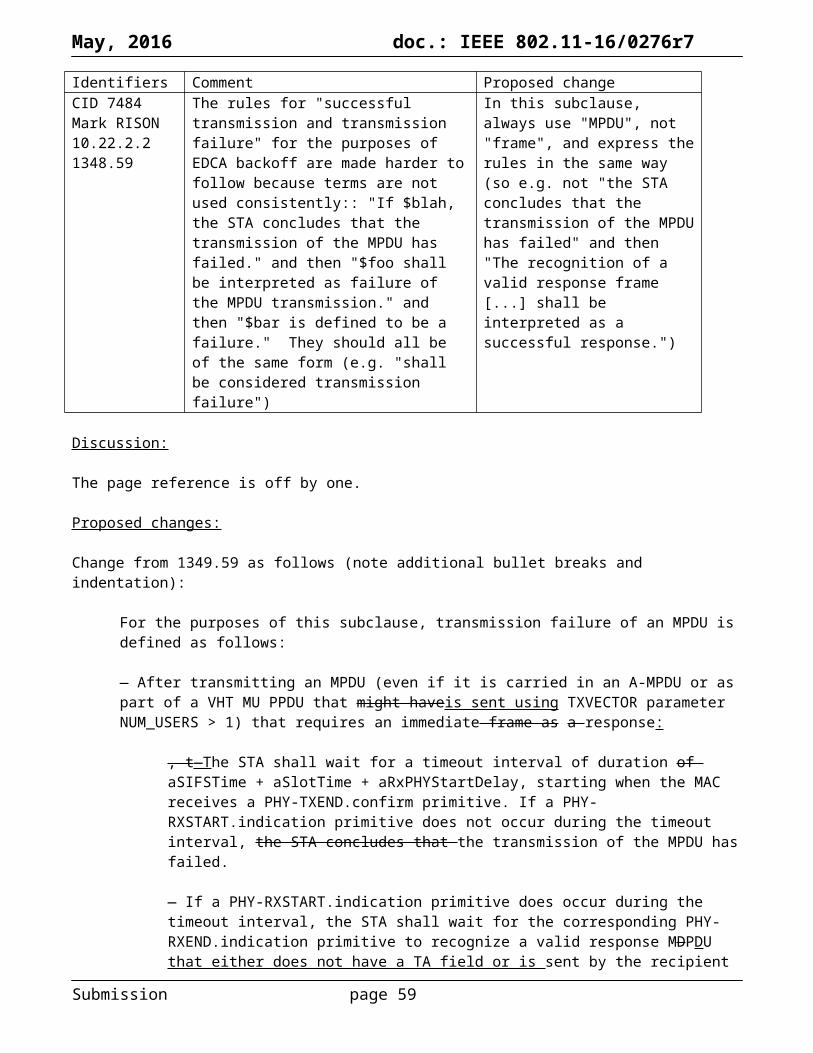
May, 2016 doc.: IEEE 802.11-16/0276r7
SupportedRatesOperationalRateSet
Non-DMG BSS: Set of integers
DMG BSS: Set of numbers
Non-DMG BSS: 1–127 excluding values from Table 9-77 108 inclusive (, for each integer inmember of the set)
DMG BSS: 0–24 , 9.1, or 12.1–12.6 , for each member of the set
Non-DMG BSS: The set of data rates (in units of 500 kb/s) that are supported by the STA that is requesting association the STA that is requesting association is able to use for communication within the BSS. The STA is able to receive at each of the data rates listed in the set. This set is a superset of the rates contained in the BSSBasicRateSet parameter.
DMG BSS: The set of MCS indexes that the AP or PCP uses for communication within the BSS.
BSSMembershipSelectorSet
Set of integers
A value from Table 9-77 (BSS membership selector value encoding), for each member of the set
The set of features that the STA that is requesting association is able to use for communication.
Change “SupportedRates,” at 176.61 to “OperationalRateSet, BSSMembershipSelectorSet,” over three lines).
Make the equivalent changes to the MLME-REASSOCIATE primitives.
Change the rows at 201.52, 202.3 and 202.48 (START.req) as follows, respectively:
BSSBasicRateSet
Set of integers
Non-DMG BSS: a value in both dot11SupportedDataRatesRxTable and dot11SupportedDataRatesTxTable1–127 inclusive (, for each integer inmember of theset)
Non-DMG BSS: The set of data rates (in units of 500 kb/s) that all STAs in the BSS are able to use for communication. All STAs in the BSS, including the STA that is creating the BSS, are able to receive and transmit at each of the data rates listed in the set.
DMG BSS: Empty.OperationalRateSet
Non-DMG BSS: Set of integers
DMG BSS: Set of numbers
Non-DMG BSS: a value in dot11SupportedDataRatesRxTable1–127 inclusive (, for each integer inmember of the set)
DMG BSS: 0–24 , 9.1, or 12.1–12.6 , for each member of the set
Non-DMG BSS: The set of data rates (in units of 500 kb/s) that the STA is able to use for communication within the BSS. The STA is able to receive at each of the data rates listed in the set. This set is a superset of the rates contained in the BSSBasicRateSet parameter.
DMG BSS: The set of MCS indexes that the peer STA uses for communication within the BSS.
BSSMembershipSelectorSet
Set of integers
A value from Table 9-77 (BSS membership selector value encoding), for each member of the set
The BSS membership selectors that represent tThe set of features that all STAs in the BSS, including the STA that is creating the BSS, are able to use for communicationshall beare supported by all STAs to joining this BSS. T, and by the STA that is creating the BSS shall be able to support each of the features represented by the set.
At 202.36 after “As defined in 9.4.2.56 (HT Capabilities element)” add “; HT-MCSes in the element are present in dot11SupportedMCSRxTable and the highest supported data rate in the element does not exceed dot11HighestSupportedDataRate” in the same cell.
Submission page 59

May, 2016 doc.: IEEE 802.11-16/0276r7
At 202.42 after “As defined in 9.4.2.57 (HT Operation element)” add “; HT-MCSes in the element are present in both dot11SupportedMCSRxTable and dot11SupportedMCSTxTable” in the same cell.
At 204.21 after “As defined in 9.4.2.158 (VHT Capabilities element)” add “; VT-MCSes in the element are present in dot11VHTRxVHTMCSMap and the highest supported data rate in the element does not exceed dot11VHTRxHighestDataRateSupported” in the same cell.
At 202.42 after “As defined in 9.4.2.57 (HT Operation element)” add “; VT-MCSes in the element are present in both dot11VHTRxVHTMCSMap and dot11VHTTxVHTMCSMap” in the same cell.
Change the row at row at 246.60 (DLS.cfm) and 247.58 (DLS.ind) as follows:
SupportedRatesOperationalRateSet
Set of integers
Non-DMG BSS: 1–127 excluding values from Table 9-77108 inclusive (, for each integer inmember of the set)
Non-DMG BSS: The set of data rates (in units of 500 kb/s) that are supported by the peer MAC entity the peer STA is able to use for direct link communication. The peer STA is able to receive at each of the data rates listed in the set.
Change the row at row at 249.3 (DLS.rsp):
SupportedRatesOperationalRateSet
Set of integers
Non-DMG BSS: a value in dot11SupportedDataRatesRxTable1–127 inclusive (, for each integer inmember of the set)
Non-DMG BSS: The set of data rates (in units of 500 kb/s) that are supported by the local MAC entity the STA is able to use for direct link communication. The STA is able to receive at each of the data rates listed in the set.
Change “SupportedRates” to “OperationalRateSet” at 246.34, 247.39, 248.41.
Change the first para of 11.1.7 Supported rates and extended supported rates advertisement as follows:
A STA shall include the rates from its OperationalRateSet parameter and the rates from the BSSBasicRateSet parameter and the BSS membership selectors from itsthe
BSSMembershipSelectorSet parameter in frames it transmits containing Supported Rates and BSS Membership Selectors elements and Extended Supported Rates and BSS Membership Selectors elementsaccording to the rules described in this subclause, except that a non-AP STA may omit the HT and VHT
BSS membership selectors , as the (V)HT capabilities are indicated through the presence of a (V)HT Capabilities element.
An HT AP for a BSS with at least one basic HT-MCS shall not, however, require that a STA that is (re)associating indicate HT in its BSSMembershipSelectorSet, as the STA’s HT capabilities are indicated through the presence of an HT Capabilities element, and similarly for VHT.
Change “elements” to “information” at 160.21,
Change “element” to “parameter” (preserving any immediately following “s” (indicating the plural)) at 222.52, 223.44, 223.47, 224.11, 228.1, 228.26, 524.62.
In 6.3.3.3.2 make sure that the only thick line within the table is that immediately below the table heading (as repeated on successive pages). Err, and in other tables too (e.g. the one in 6.3.8.4.2).
At 511.12 and 511.27 change “–1 to 7920 (for each integer in the set)” to “–1 to 7920, for each member of the set”.
Submission page 60

May, 2016 doc.: IEEE 802.11-16/0276r7
At p2.44 after ““x to y”” add “or “x–y””.
In Table 9-338 add “and BSS Membership Selectors” after “Supported Rates” (6 instances).
In Table 9-339 add “and BSS Membership Selectors” after “Supported Rates” (6 instances).
In Table 9-361 add “and BSS Membership Selectors” after “Supported Rates” (3 instances).
In Table 9-362 add “and BSS Membership Selectors” after “Supported Rates” (3 instances).
Wording of 9.4.2.3 Supported Rates and BSS Membership Selectors element does not match that of 9.4.2.13 Extended Supported Rates and BSS Membership Selectors element.
Make it clearer that BSS membership selectors are always “basic”.
“and BSS Membership selectors” missing in TDLS Setup Request/Response.
Proposed resolution:
REVISED
Make the changes shown under “Proposed changes” for CIDs 7278, 7280-7290, 7292 in <this document>, which rationalise the SAP signalling of rates and MCSes, require that only rates/MCSes supported by the device are advertised, keep rates and membership selectors separate, avoid the use of the term “SupportedRate” and generally are full of wholesome goodness.
Submission page 61

May, 2016 doc.: IEEE 802.11-16/0276r7
Identifiers Comment Proposed changeCID 7213Mark RISON12.3.11.32574.45
The term "MU-capable STA" is not defined. It should be defined as an AP that supports MU-MIMO tx or a non-AP STA that is MU beamformee capable. Alternatively, since the term is hardly used (3 instances, pp. 78, 1058, 2574), and where it is used it is only used for non-AP STAs, replace it with "MU beamformee capable"
As it says in the comment
Discussion:
Here are the three instances of the term “MU-capable STA”:
78.22: With DL-MU-MIMO the AP can create up to four A-MPDUs, each carrying MPDUs destined for an associated MU-capable STA.1058.19: […] during which the primary 20 MHz channel is busy due to the transmission of one or more spatial streams by the AP to MU-capable STAs2574.47: An MU-capable STA shall support reception of VHT MU PPDUs with the total number of space-time streams across the N_user users being […]
The term “MU beamformee capable” is used 14 times.
Proposed resolution:
REVISED
Change “MU-capable” to “MU beamformee capable” at 78.22, 1058.19, 2574.47.
Submission page 62

May, 2016 doc.: IEEE 802.11-16/0276r7
Identifiers Comment Proposed changeCID 7377Mark RISON12.6.1.3.21966.22
"A STA performing secure password-based, or PSK, authentication uses" -- what is "secure PSK"? Is there an insecure PSK? If so, insecure PSK should be defined and obsoleted. If not, "secure" should be deleted
Change to "A STA performing password-based authentication can use"
Discussion:
The context is:
A STA and AP establish an initial security association via the following steps:a) The STA selects an authorized ESS by selecting among APs that advertise an appropriate SSID.b) The STA then performs IEEE Std 802.11 authentication followed by association to the chosen
AP. Confirmation of security parameters takes place during association. A STA performing IEEE Std 802.1X authentication uses Open System authentication. A STA performing secure password-based, or PSK, authentication uses SAE authentication.NOTE 1—It is possible for more than one PMKSA to exist. As an example, a second PMKSA might come into existence through PMKSA caching. A STA might leave the ESS and flush its cache. Before its PMKSA expires in the AP’s cache, the STA returns to the ESS and establishes a second PMKSA from the AP’s perspective.NOTE 2—An attack altering the security parameters is detected by the key derivation procedure.NOTE 3—IEEE Std 802.11 Open System authentication provides no security, but is included to maintain backward compatibility with the IEEE Std 802.11 state machine (see 11.3 (STA authentication and association)).
The wording is ambiguous, but can certainly be read as suggesting that PSK-based authentication is insecure. This is only true if the passphrase used is weak (because this is, unlike SAE, vulnerable to brute-force offline cracking). It is not desirable to cast an overly-broad aspersion on PSK (which is, after all, a security mechanism currently promulgated by a key industry body for non-enterprise use).
Proposed changes:
REVISED
At 1966.22 change “A STA performing secure password-based, or PSK, authentication uses SAE authentication.” to “A STA performing password-based authentication uses PSK or SAE authentication.”
At 1966.33 add an extra “NOTE 4—PSK authentication using a weak passphrase is vulnerable to offline brute-force cracking. SAE authentication is not vulnerable to this.” and renumber the subsequent NOTEs in this subclause.
Submission page 63

May, 2016 doc.: IEEE 802.11-16/0276r7
CID 7277Mark RISON11.24.6.41771.20
What does "or clock estimate" mean? Delete NOTE 2
Discussion:
The wording is actually “clock offset estimate”, and this term is defined in Equation (11-6) at 1772.45.
Proposed changes:
In Figure 11-37 change NOTE 2 as follows:
NOTE 2—Initiating STA can compute either an RTT orand a clock offset estimate
Add a paragraph break after the sentence (second sentence of the para, ending “802.1AS”) at 1772.41.
Add a NOTE at 1772.47, italicising t1 and t4 and using a consistent prime symbol after them throughout this subclause:
NOTE—The initiating STA might also track this clock offset over time to derive an estimate of the difference between the initiating STA’s time base and the responding STA’s time base, and thereby improve the accuracy of its derivation of t1’ and t4’ from the TOD and TOA fields.
Number all the NOTEs in this subclause, and also in Subclause 9.6.8.33.
Add a space after “time base,” at 1159.22.
Proposed resolution:
REVISED
Make the changes shown under “Proposed changes” for CID 7277 in <this document>, which clarify the intent of clock offset estimation.
Submission page 64

May, 2016 doc.: IEEE 802.11-16/0276r7
Identifiers Comment Proposed changeCID 7208Mark RISON6.3.58339.1
For MLME-FINETIMINGMSMT.request, "Set to the value of t1 (see Figure 6-17)" is misleading because it is not set to the t1 in the figure but to the time for the previous request. Ditto t4. And for the .indication it's the time in the FTM frame, which is again not the t1 and t4 in the figure
Change the text as indicated in the comment
Discussion:
The table in 6.3.58.2.2 for MLME-FINETIMINGMSMT.request says (some rows/columns elided):
Name DescriptionFollow Up Dialog Token The dialog token of a Fine Timing Measurement frame which the current
frame follows. See 11.24.6 (Fine timing measurement procedure).t1 Set to the value of t1 (see Figure 6-17 (Fine timing measurement primitives
and timestamps capture)) expressed in units of picoseconds.t4 Set to the value of t4 (see Figure 6-17 (Fine timing measurement primitives
and timestamps capture)) in units of picoseconds.
where Figure 6-17 is:
However, the t1 and t4 in the FTM frame are not the t1 and t4 shown in this figure, but the t1 and t4 for the previous FTM frame.
Similarly, in the table in 6.3.58.4.2 for MLME-FINETIMINGMSMT.indication, the t1 and t4 are not from the points indicated in the figure, but from the contents of the FTM frame (and so the t1 and t4 for the previous FTM frame).
Additionally, when the Follow Up Dialog Token or Dialog Token is 0 (at the start or end of the FTM session respectively), some of t1-t4 (and their corresponding errors) are unavailable or useless.
There are various other small issues with the table wording too.
Proposed changes:
Change the cells of the table in 6.3.58.2.2 (.request) as follows:
Name DescriptionDialog Token The dialog token to identify the Fine Timing Measurement transactionframe.
Submission page 65
May, 2016 doc.: IEEE 802.11-16/0276r7
A value of 0 indicates the end of the transactionFTM session.Follow Up Dialog Token The dialog token of a Fine Timing Measurement frame which the current
frame follows, or 0 if there is no such frame. See 11.24.6 (Fine timing measurement procedure).
t1 Set to tThe value of t1 (see Figure 6-17 (Fine timing measurement primitives and timestamps capture)) for the Fine Timing Measurement frame identified by the Follow Up Dialog Token, expressed in units of picoseconds, or null if the Follow Up Dialog Token is 0.
Max t1 ErrorExponent
The maximum error in the t1 value. This is represented using a function of the Max t1 Error Exponent parameter as defined in Equation (8-4), or is null if the Follow Up Dialog Token is 0.
t4 Set to tThe value of t4 (see Figure 6-17 (Fine timing measurement primitives and timestamps capture)) for the Fine Timing Measurement frame identified by the Follow Up Dialog Token, in units of picoseconds, or null if the Follow Up Dialog Token is 0.
Max t4 ErrorExponent
The maximum error in the t4 value. This is represented using a function of the Max t4 Error Exponent parameter as defined in Equation (8-4), or is null if the Follow Up Dialog Token is 0.
Change the cells of the table in 6.3.58.3.2 (.confirm) as follows:
Name DescriptionDialog Token The dialog token to identify the Fine Timing Measurement transactionframe.
A value of 0 indicates the end of the transactionFTM session.t1 Set to tThe value of t1 (see Figure 6-17 (Fine timing measurement primitives
and timestamps capture)) for the Fine Timing Measurement frame identified by the Dialog Token, expressed in units of picoseconds, or null if the Dialog Token is 0.
Max t1 ErrorExponent
The maximum error in the t1 value. This is represented using a function of the Max t1 Error Exponent parameter as defined in Equation (8-4), or is null if the Dialog Token is 0.
t4 Set to tThe value of t4 (see Figure 6-17 (Fine timing measurement primitives and timestamps capture)) for the Fine Timing Measurement frame identified by the Dialog Token, in units of picoseconds, or null if the Dialog Token is 0.
Max t4 ErrorExponent
The maximum error in the t4 value. This is represented using a function of the Max t4 Error Exponent parameter as defined in Equation (8-4), or is null if the Dialog Token is 0.
Change the cells of the table in 6.3.58.4.2 (.indication) as follows:
Name DescriptionDialog Token The dialog token to identify the Fine Timing Measurement transactionframe.
A value of 0 indicates the end of the transactionFTM session.Follow Up Dialog Token The dialog token of a Fine Timing Measurement frame which the current
frame follows, or 0 if there is no such frame. See 11.24.6 (Fine timing measurement procedure).
t1 Set to tThe value of t1 (see Figure 6-17 (Fine timing measurement primitives and timestamps capture)) for the Fine Timing Measurement frame identified by the Follow Up Dialog Token, contained in the Fine Timing Measurement frame identified by the Dialog Token, expressed in units of picoseconds, or null if the Follow Up Dialog Token is 0.
Max t1 Error The maximum error in the t1 value. This is represented using a function of
Submission page 66

May, 2016 doc.: IEEE 802.11-16/0276r7
Exponent the Max t1 Error Exponent parameter as defined in Equation (8-4), or is null if the Follow Up Dialog Token is 0.
t4 Set to tThe value of t4 (see Figure 6-17 (Fine timing measurement primitives and timestamps capture)) for the Fine Timing Measurement frame identified by the Follow Up Dialog Token, contained in the Fine Timing Measurement frame identified by the Dialog Token, in units of picoseconds, or null if the Follow Up Dialog Token is 0.
Max t4 ErrorExponent
The maximum error in the t4 value. This is represented using a function of the Max t4 Error Exponent parameter as defined in Equation (8-4), or is null if the Follow Up Dialog Token is 0.
t2 Set to tThe value of t2 (see Figure 6-17 (Fine timing measurement primitives and timestamps capture)) for the Fine Timing Measurement frame identified by the Dialog Token, expressed in units of picoseconds, or null if the Dialog Token is 0.
Max t2 ErrorExponent
The maximum error in the t2 value. This is represented using a function of the Max t2 Error Exponent parameter as defined in Equation (8-4), or is null if the Dialog Token is 0.
t3 Set to tThe value of t3 (see Figure 6-17 (Fine timing measurement primitives and timestamps capture)) for the Fine Timing Measurement frame identified by the Dialog Token, in units of picoseconds, or null if the Dialog Token is 0.
Max t3 ErrorExponent
The maximum error in the t3 value. This is represented using a function of the Max t3 Error Exponent parameter as defined in Equation (8-4), or is null if the Dialog Token is 0.
In Figure 6-17 on p. 346 of 11mc/D5.2, move the MLME-FINETIMINGMSMT.indication arrow such that it is below the point at which t3 occurs.
Proposed resolution:
REVISED
Make the changes shown under “Proposed changes” for CID 7208 in <this document>, which effect the requested changes.
Submission page 67
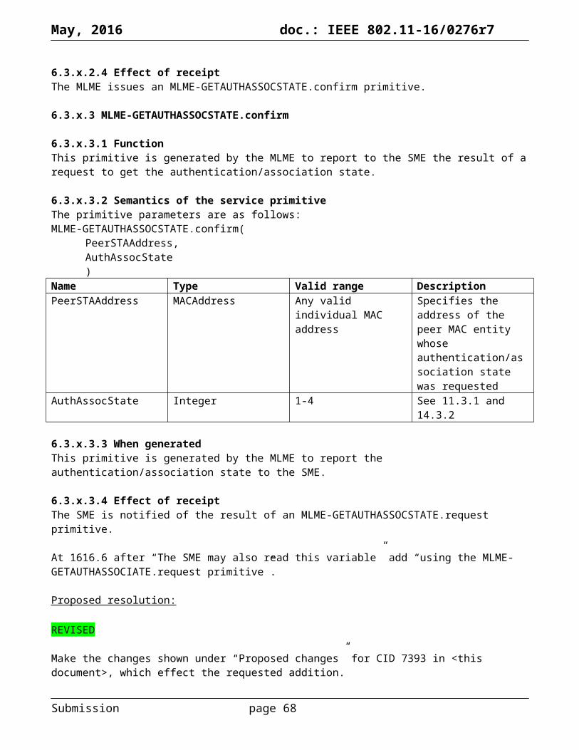
May, 2016 doc.: IEEE 802.11-16/0276r7
Identifiers Comment Proposed changeCID 6431Mark RISON
Why does the DSSS PHY have such a big max MPDU length? All other PHYs (including HR/DSSS) have a maximum of 4095, and furthermore it's not clear what this means in terms of the max A-MSDU size which can be transported in a DSSS-format PPDU sent between HT STAs
Change 2^13 to 2^12 at 2175.14, 2176.24, 2188.19
Discussion:
This change was accepted in the previous round. However, a couple of other locations allowing for 8191-octet DSSS PPDUs were missed.
Also, something has gone wrong with one of the xrefs.
Proposed changes:
Change the following cells in Table 9-19—Maximum data unit sizes (in octets) and durations (in microseconds) as indicated (not all cells in the table shown):
Non-HT non-VHTnon-DMG PPDUand non-HTduplicate PPDU
A-MSDU size 3839 or 4065 (seeNOTE 2) or 7935(HT STA, see alsoTable 9-161(Subfields of the HTCapabilityInformation field)) orN/A (non-HT STA,see also 10.12 (A-MSDU operation))
PSDU size (seeNOTE 7)
213–1 (Clause 15(DSSS PHYspecification for the2.4 GHz banddesignated for ISMapplications), seeTable 15-5 (DSSSPHY characteristics))212–1 (others, seeTable 15-5 (DSSSPHY characteristics),Table 16-64, Table 17-21(OFDM PHYcharacteristics),Table 18-6 (ERPcharacteristics))
Submission page 68

May, 2016 doc.: IEEE 802.11-16/0276r7
Proposed motion:
Make the changes shown under “Proposed changes” for CID 6431 in <this document>.
Submission page 69
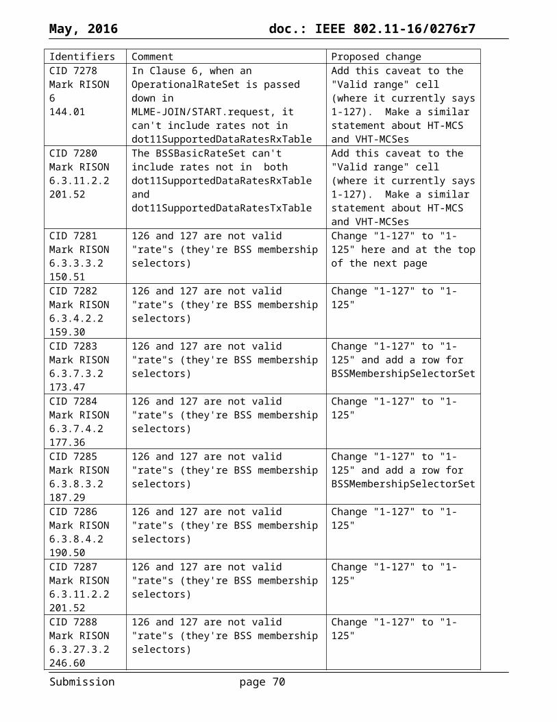
May, 2016 doc.: IEEE 802.11-16/0276r7
Identifiers Comment Proposed changeCID 7294Mark RISON17.4.42306.23
These values are not correct. The time to the start of the DATA field is 20 us (see F17-4)
Change the values to 20, 40 and 80 (microseconds)
CID 7295Mark RISON17.5.42318.57
This value is not correct. The time to the start of the DATA field is 20 us (see F17-4)
Change the value to 20 (microseconds)
CID 7296Mark RISON19.4.42415.62
This value is not correct. The time to the start of the DATA field is at least 36 us for MF and can be as little as 28 us for GF (see F19-1)
Change to "36 <micro>s for MF and 28 <micro>s for GF"
Discussion:
Per CID 7293, aRxPHYStartDelay is the delay from the start of the PPDU at the receiver’s antenna to the issuance of the PHY-RXSTART.indication primitive. This primitive indicates that the PHY header has been received, and carries the corresponding RXVECTOR.
This delay is used in the following contexts (only):
1275.30: A STA that used information from an RTS frame as the most recent basis to update its NAV setting is permitted to reset its NAV if no PHY-RXSTART.indication primitive is received from the PHY during a period with a duration of (2 × aSIFSTime) + (CTS_Time) + aRxPHYStartDelay + (2 × aSlotTime) starting when the MAC receives a PHY-RXEND.indication primitive corresponding to the detection of the RTS frame.
1275.30: Similar for L-SIG TXOP protection, which is now obsolete.
1278.8: After transmitting an RTS frame, the STA shall wait for a CTSTimeout interval with a value of aSIFSTime + aSlotTime + aRxPHYStartDelay. This interval begins when the MAC receives a PHY-TXEND.confirm primitive. If a PHY-RXSTART.indication primitive does not occur during the CTSTimeout interval, the STA shall conclude that the transmission of the RTS frame has failed
1281.32: After transmitting an MPDU that requires an Ack frame as a response (see Annex G), the STA shall wait for an AckTimeout interval, with a value of aSIFSTime + aSlotTime + aRxPHYStartDelay. This interval begins when the MAC receives a PHY-TXEND.confirm primitive. If a PHY-RXSTART.indication primitive does not occur during the AckTimeout interval, the STA concludes that the transmission of the MPDU has failed
1349.61: After transmitting an MPDU (even if it is carried in an A-MPDU or as part of a VHT MU PPDU that might have TXVECTOR parameter NUM_USERS > 1) that requires an immediate frame as a response, the STA shall wait for a timeout interval of duration of aSIFSTime + aSlotTime + aRxPHYStartDelay, starting when the MAC receives a PHY-TXEND.confirm primitive. If a PHY-RXSTART.indication primitive does not occur during the timeout interval, the STA concludes that the transmission of the MPDU has failed.
In all these cases, the purpose of the “+ aRxPHYStartDelay” is to allow for the time taken by the PHY to detect the (start of the) PPDU and to notify the MAC of this. It really doesn’t matter what this is, it just needs to be known by the MAC so it knows when to timeout for the PHY-RXSTART.indication. By definition, it has to be the time to the end of the PHY header plus any PHY processing time.
On this basis, it should really be implementation-dependent, like most of the PHY characteristics. However, this suggestion was rejected (see CID 6477). So then the next best answer is to make it equal to the duration of the PHY preamble and header, i.e. the earliest time the PHY could tell the MAC. Here is a table comparing the
Submission page 70

May, 2016 doc.: IEEE 802.11-16/0276r7
duration of the PHY preamble (aPreambleLength, “PHY’s preamble length (in microseconds [rounded up])”), the duration of the PHY header (aPHYHeaderLength, “PHY’s header length (in microseconds [rounded up]), excluding aPHYSigTwoLength if present”; aPHYSigTwoLength is only present for HT and its descendants, and is 8 µs), and the current values of aRxPHYStartDelay (locations given); the cases where aRxPHYStartDelay != aPreambleLength + aPHYHeaderLength are emboldened (some are arguably due to bugs in the table, though, as shown highlighted in yellow):
Format aPreambleLength (µs) aPHYHeaderLength (µs) aRxPHYStartDelay (µs)DSSS 144 (2221.16) 48 (2221.18) 192 (2220.50)HR/DSSS/long 144 (2246.63) 48 (2247.5) 192 (2246.50)HR/DSSS/short 144 (2246.63) 48 (2247.5) 96 (2246.50)OFDM 20 MHz 16 (2306.36) 4 (2306.37) 25 (2306.22)OFDM 10 MHz 32 (2306.36) 8 (2306.37) 49 (2306.22)OFDM 5 MHz 64 (2306.36) 16 (2306.37) 97 (2306.22)ERP-OFDM 20 (2319.13) 4 (2319.15) 24 (2318.57)ERP-DSSS/CCK/long 20 (2319.13) 4 (2319.15) 192 (2318.58)ERP-DSSS/CCK/short 20 (2319.13) 4 (2319.15) 96 (2318.59)HT_MF 16 (2416.17) 4 (2416.27) 33 (2415.62)HT_GF 16 (2416.17) 4 (2416.27) 33 (2415.62)DMG Control Not specified, though there is a
aControlPHYPreambleLength of 4291 ns (2486.48)
Not specified 10 (2486.35)
DMG SC Not specified, though there is a aDataPreambleLength of 1891 ns (2486.46)
Not specified 3.6 (2486.36)
DMG OFDM Not specified, though there is a aDataPreambleLength of 1891 ns (2486.46)
Not specified 3.3 (2486.36)
VHT 16 (2416.17), from HT 4 (2416.27), from HT Not explicitly specified, because only specified for “MF” and “GF”, from HT
TVHT 16 (2416.17) × 7.5 or 5.625 (2664.48), from HT with adjustment factor
4 (2416.27) × 7.5 or 5.625 (2664.48), from HT with adjustment factor
Not explicitly specified, because only specified for “MF” and “GF”, from HT
Examination of all this information leads to the following observations:
There are lots of bugs in the tables! Arguably, aRxPHYStartDelay needs to be the worst case (e.g. 192 µs for HR/DSSS), unless the MAC
knows (e.g. from the multirate rules) that the worst case is not possible The spec glosses over the fact that e.g. for HT_MF and VHT there will be two PHY-
RXSTART.indications, one for the legacy preamble and header and one for the HT header It’s even worse for VHT, because in addition to the preamble, legacy header and aPHYSigTwoLength
there needs to be something to account for the VHT-STF, VHT-LTF and VHT-SIG-B (which is the point at which you get the APEP_LENGTH and, for MU, the MCS)
The TVHT spec doesn’t really work, because the aPreambleLength and aPHYHeaderLength are supposed to be integers
DMG … shrug. Let’s hope the aRxPHYStartDelay values are right!
Proposed changes:
Submission page 71
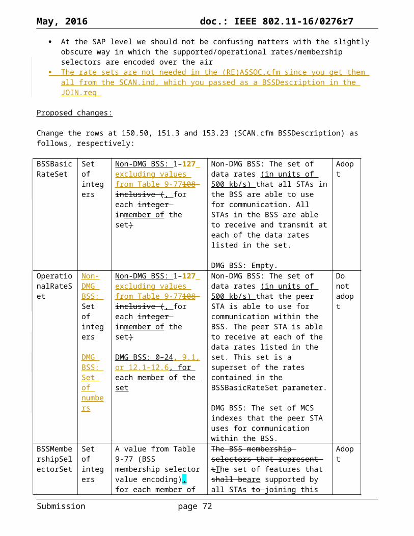
May, 2016 doc.: IEEE 802.11-16/0276r7
Make the changes shown below, where the changes are described as “<old value> → <new value> (<the location of each change>):
Format aPreambleLength (µs) aPHYHeaderLength (µs) aRxPHYStartDelay (µs)DSSSHR/DSSS/longHR/DSSS/short 144 → 72 (2246.63) 48 → 24 (2247.5)OFDM 20 MHz 25 → 20 (2306.22)OFDM 10 MHz 49 → 40 (2306.22)OFDM 5 MHz 96 → 80 (2306.22)ERP-OFDM 20 → 16 (2319.13) 24 → 20 (2318.57)ERP-DSSS/CCK/long 20 → 144 (2319.13) 4 → 48 (2319.15)ERP-DSSS/CCK/short 20 → 72 (2319.13) 4 → 24 (2319.15)HT_MF 33 → 28 (2415.62)HT_GF 4 → N/A (2416.27) 33 → 24 (2415.62)DMG ControlDMG SCDMG OFDM
Add a new row to Table 21-29 (VHT PHY characteristics) with “aRxPHYStartDelay” in the left-hand cell and “36 + 4 × the maximum possible value for NVHT-LTF supported + 4 (see NOTE 2)” in the right-hand cell.
Add a numbered NOTE to Table 21-29 (VHT PHY characteristics):
NOTE 2—This value arises from the time to the end of VHT-SIG-B (see Figure 21-4 (VHT PPDU format)) plus the need to decode the first symbol of the Data field in order to extract the SERVICE field and check the CRC it contains.
Add a new row to Table 22-25 (TVHT PHY characteristics) with “aRxPHYStartDelay” in the left-hand cell and “(36 + 4 × the maximum possible value for NVHT-LTF supported + 4) × 7.5 (6 and 7 MHz channels) or 5.625 (8 MHz channels) (see NOTE 2)” in the right-hand cell.
Add a numbered NOTE to Table 22-25 (TVHT PHY characteristics):
NOTE 2—This value arises from the time to the end of TVHT-SIG-B (see Figure 22-1 (VHT PPDU format in TVWS bands)) plus the need to decode the first symbol of the Data field in order to extract the SERVICE field and check the CRC it contains.
Proposed resolution for CID 7294:
ACCEPTED
Proposed resolution for CID 7295:
ACCEPTED (note: this was REJECTED in motion 195)
Note to the editor: the subclause indicated by the commenter is wrong (should be 18.5.4). The page and line are correct.
Proposed resolution for CID 7296:
REVISED
Submission page 72

May, 2016 doc.: IEEE 802.11-16/0276r7
Make the changes shown under “Proposed changes” for CID 7296 in <this document>, which correct the aPreambleLength, aPHYHeaderLength and aRxPHYStartDelay for various PHYs including HT.
Note to the commenter: the times are to the end of HT-SIG, not to the start of the Data field, so are 28/24 us for MF/GF, not 36/28 us.
Submission page 73
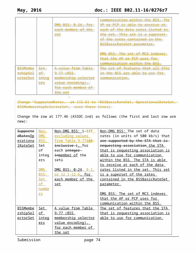
May, 2016 doc.: IEEE 802.11-16/0276r7
Identifiers Comment Proposed changeCID 7774Mark RISON9.6.21.21240.19
"One or more elements are present in this frame" -- these are already covered above
Delete this row
CID 7776Mark RISON9.6.21.31241.24
"One or more elements are present in this frame" -- these are already covered above
Delete this row
Discussion:
The context is (note that CID 7776 cites the text incorrectly: it’s “can appear” not “are present”):
Submission page 74

May, 2016 doc.: IEEE 802.11-16/0276r7
Proposals were put forward in Macau to resolve these comments as follows:
REJECTED (MAC: 2016-03-15 09:26:12Z): The cited text allows elements that are not listed in orders 1-9 to be included.
REJECTED (MAC: 2016-03-15 09:31:40Z): The cited text allows elements that are not listed in orders 1-9 to be included. The description refers to 11.33 which lists the elements that can be present.
However, the cited text is too vague. Do the “one or more elements” include the elements in the previous orders? Since Session Transition (order 5) is mandatory, this would be a worthless statement. So I assume it means additional elements. But then is the first location (1240.19) really saying you need to include at least one additional element, without saying which? This is odd too. So I think this is trying to say 0 or more, like the second. Also, does “an element can be included only once” include things like vendor-specific IEs? Assuredly not. So I assume it’s not intended to refer to the frame, just to the things covered by the last order in the Action field (i.e. the things 11.33 brings in).
Proposed resolution (for both CIDs):
REVISED
Change the cell at the referenced location to “Zero or more additional elements are present, as defined in 11.33.1. Each of these elements is not present more than once in the frame.”
Submission page 75
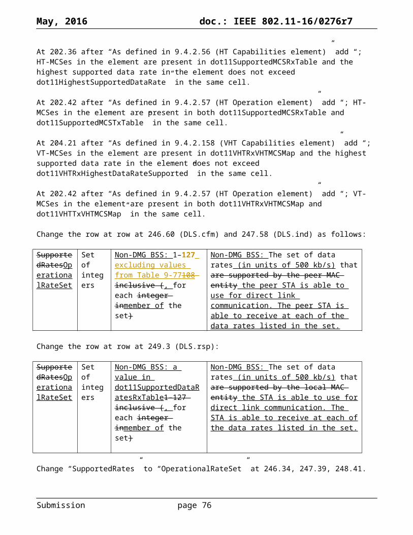
May, 2016 doc.: IEEE 802.11-16/0276r7
Submission page 76

May, 2016 doc.: IEEE 802.11-16/0276r7
Identifiers Comment Proposed changeCIDMark RISON
Discussion:
Proposed changes:
Proposed resolution:
REVISED
Make the changes shown under “Proposed changes” for CID in <this document>, which
Submission page 77

May, 2016 doc.: IEEE 802.11-16/0276r7
Font size error at 1766.42 (after “NOTE”), 163.36 and 165.11 (in “SAE”), 2052.41 (in “else if”), 159.17 (in “SelectedBSS”).
Submission page 78

May, 2016 doc.: IEEE 802.11-16/0276r7
References:
802.11mc/D5.0
Submission page 79