support.avaya.comsupport.avaya.com/elmodocs2/octel/config/cn4003.doc · web viewprogram them as...
TRANSCRIPT
Configuration Note 4003 - Ver H (3/01)
Avaya System 85/Definity G2
ANALOGPORTS
TRUNK
TDMBUS
CPU
AnalogTICs
DIGITALPORTS
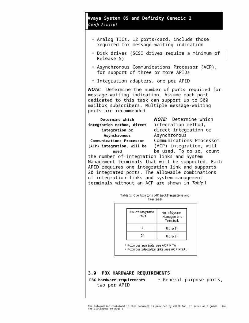
System 85/Definity G2 Octel 350
Minimum SoftwareRelease 1.5
Minimum ReleaseR2, V2
LINE
XXX
VOICE PATH
Multiple Return to OperatorOutcalling
Auto-AttendantMessage Waiting On/Off
Call ID
PBXINTEGRATION
DEVICE
RS-232 Distribution Board
1.0 METHOD OF INTEGRATIONThe AT&T System 85 PBX Integration Device (APID/85) simulates two digital stations on the
Avaya PBX. Analog line circuits provide the voice path and appear on the configuration of the APID as bridged line appearances. When a call is received by the APID, the digital display provides call information. The APID collects this data and transmits it to the Octel 350. The Octel 350 then answers the call with the appropriate personal greeting. Message-waiting set and cancel commands are performed through the PBXs Leave Word Calling feature, over analog ports dedicated to this function.
2.0 OCTEL 350 ORDERING INFORMATION• AT&T System 85/Definity
Generic 2 APID, includes:- RS-232 integration software- In-band integration software
• Analog TICs, 12 ports/card, include those required for message-waiting indication
• Disk drives (SCSI drives require a minimum of Release 5)
• Asynchronous Communications Processor (ACP), for support of three or more APIDs
Disclaimer: Configuration Notes are designed to be a general guide reflecting AVAYA Inc.’s experience configuring its systems. These notes cannot anticipate every configuration possibility given the inherent variations in all hardware and software products. Please understand that you may experience a problem not detailed in a Configuration Note. If so, please notify the TAC/TSO at (408) 922-1822 and if appropriate we will include it in our next revision. AVAYA Inc. accepts no responsibility for errors or omissions contained herein.
O c t e l 3 5 0
M e s s a g e S e r v e r
The APID appears as two digital stations on the PBX and collects
call integration information
Octel 350 requirements
Avaya System 85 and Definity Generic 2 C o n f i d e n t i a l
2
• Integration adapters, one per APID
NOTE: Determine the number of ports required for message-waiting indication. Assume each port dedicated to this task can support up to 500 mailbox subscribers. Multiple message-waiting ports are recommended.
NOTE: Determine which integration method, direct integration or Asynchronous Communications Processor (ACP) integration, will be used. To do so, count the number of
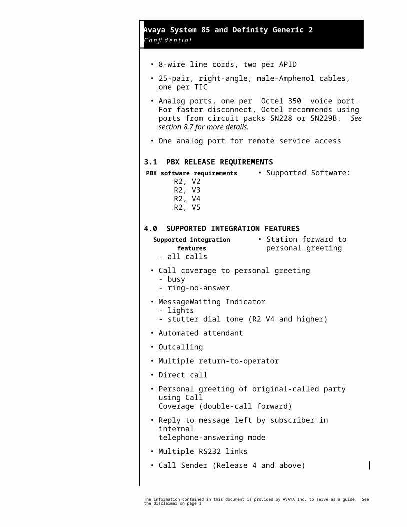
integration links and System Management terminals that will be supported. Each APID requires one integration link and supports 20 integrated ports. The allowable combinations of integration links and system management terminals without an ACP are shown in Table 1.
Table 1. Combinations of Direct Integrations and Terminals.
No. of Integration Links
1
22
No. of SystemManagement
Terminals
Up to 31
Up to 21
1 For more terminals, use ACP MTA.2 For more integration links, use ACP MSA.
3.0 PBX HARDWARE REQUIREMENTS• General purpose ports, two per
APID
• 8-wire line cords, two per APID
• 25-pair, right-angle, male-Amphenol cables, one per TIC
• Analog ports, one per Octel 350 voice port. For faster disconnect, Octel recommends using ports from circuit packs SN228 or SN229B. See section 8.7 for more details.
• One analog port for remote service access
3.1 PBX RELEASE REQUIREMENTS• Supported Software:
R2, V2R2, V3
The information contained in this document is provided by AVAYA Inc. to serve as a guide. See the disclaimer on page 1
Determine which integration method, direct integration or
Asynchronous Communications Processor (ACP) integration, will
be used
PBX hardware requirements
PBX software requirements
Avaya System 85 and Definity Generic 2 C o n f i d e n t i a l
3
R2, V4R2, V5
4.0 SUPPORTED INTEGRATION FEATURES• Station forward to personal
greeting- all calls
• Call coverage to personal greeting- busy- ring-no-answer
• MessageWaiting Indicator- lights- stutter dial tone (R2 V4 and higher)
• Automated attendant
• Outcalling
• Multiple return-to-operator
• Direct call
• Personal greeting of original-called party using Call Coverage (double-call forward)
• Reply to message left by subscriber in internal telephone-answering mode
• Multiple RS232 links
• Call Sender (Release 4 and above)
• Multiple Personal Greetings (Release 4 and above)
5.0 CONFIGURING THE SYSTEM 85/DEFINITY G2 TO INTEGRATE
All subscriber extensions must be programmed with the name entry field either left blank or with the extension number as part of the field. This programming is setup using PROC 12. The extension can be placed anywhere in the name field. The field can contain up to 15 characters; therefore, abbreviations may be necessary. For example:
Smith,J.507 or 507.J,Smith
The information contained in this document is provided by AVAYA Inc. to serve as a guide. See the disclaimer on page 1
Supported integration features
Configuring the PBX to integrate
All subscriber extensions must be programmed with the name entry field either left blank or with the extension number as
part of the field
Avaya System 85 and Definity Generic 2 C o n f i d e n t i a l
4
Do not leave any blank spaces between the extension number and the name/initial.
These changes to the names field are compatible with the Avaya Integrated Directory feature if commas instead of periods are used to separate the first initial from the last name, as shown in the above example. A period can still be used to separate the extension number from the name, and the extension number may be placed before or after the name.
NOTE: Save all translation changes to the back-up tape.
The following System 85/Definity G2 programming instructions are applicable when using the SMT (System Management Terminal) or MAAP (Maintenance And Administration Panel). If your PBX is programmed using a CSM (Central System Manager) terminal, refer to section 9.0 of this note.
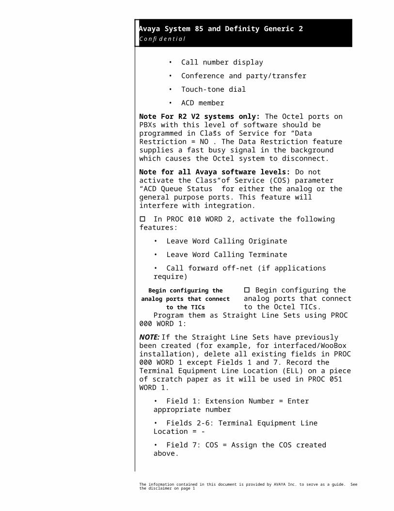
o Create the Class of Service (COS) for the analog and general purpose ports. In PROC 010 WORD 1, activate the following features:
• Call forward busy/don’t answer
• Call forward follow me
• Call number display
• Conference and party/transfer
• Touch-tone dial
• ACD member
Note For R2 V2 systems only: The Octel ports on PBXs with this level of software should be programmed in Class of Service for “Data Restriction = NO”. The Data Restriction feature supplies a fast busy signal in the background which causes the Octel system to disconnect.
Note for all Avaya software levels: Do not activate the Class of Service (COS) parameter “ACD Queue Status” for either the analog or the general purpose ports. This feature will interfere with integration.
o In PROC 010 WORD 2, activate the following features:
• Leave Word Calling Originate
• Leave Word Calling Terminate
• Call forward off-net (if applications require)
o Begin configuring the analog ports that connect to the Octel TICs.
Program them as Straight Line Sets using PROC 000 WORD 1:
NOTE: If the Straight Line Sets have previously been created (for example, for interfaced/WooBox installation), delete all existing fields in
The information contained in this document is provided by AVAYA Inc. to serve as a guide. See the disclaimer on page 1
Begin configuring the analog ports that connect to the TICs
Avaya System 85 and Definity Generic 2 C o n f i d e n t i a l
5
PROC 000 WORD 1 except Fields 1 and 7. Record the Terminal Equipment Line Location (ELL) on a piece of scratch paper as it will be used in PROC 051 WORD 1.
• Field 1: Extension Number = Enter appropriate number
• Fields 2-6: Terminal Equipment Line Location = -
• Field 7: COS = Assign the COS created above.
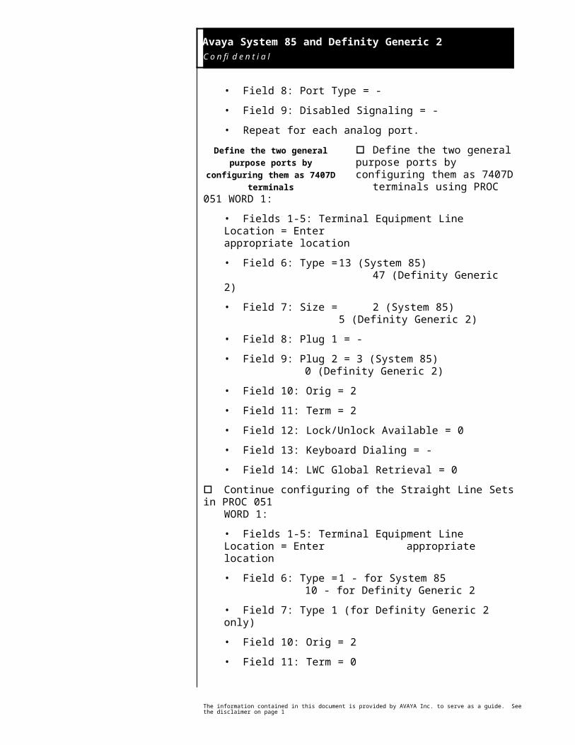
• Field 8: Port Type = -
• Field 9: Disabled Signaling = -
• Repeat for each analog port.
o Define the two general purpose ports by configuring them as 7407D
terminals using PROC 051 WORD 1:
• Fields 1-5: Terminal Equipment Line Location = Enter appropriate location
• Field 6: Type = 13 (System 85) 47 (Definity Generic 2)
• Field 7: Size = 2 (System 85)5 (Definity Generic 2)
• Field 8: Plug 1 = -
• Field 9: Plug 2 = 3 (System 85)0 (Definity Generic 2)
• Field 10: Orig = 2
• Field 11: Term = 2
• Field 12: Lock/Unlock Available = 0
• Field 13: Keyboard Dialing = -
• Field 14: LWC Global Retrieval = 0
o Continue configuring of the Straight Line Sets in PROC 051 WORD 1:
• Fields 1-5: Terminal Equipment Line Location = Enter appropriate location
• Field 6: Type = 1 - for System 8510 - for Definity Generic 2
• Field 7: Type 1 (for Definity Generic 2 only)
The information contained in this document is provided by AVAYA Inc. to serve as a guide. See the disclaimer on page 1
Define the two general purpose ports by configuring them as
7407D terminals
Avaya System 85 and Definity Generic 2 C o n f i d e n t i a l
6
• Field 10: Orig = 2
• Field 11: Term = 0
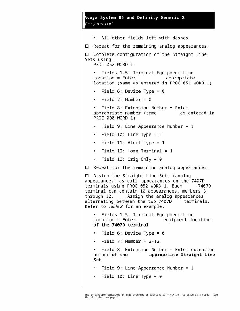
• All other fields left with dashes
o Repeat for the remaining analog appearances.
o Complete configuration of the Straight Line Sets using PROC 052 WORD 1.
• Fields 1-5: Terminal Equipment Line Location = Enter appropriate location (same as entered in PROC 051 WORD 1)
• Field 6: Device Type = 0
• Field 7: Member = 0
• Field 8: Extension Number = Enter appropriate number (same as entered in PROC 000 WORD 1)
• Field 9: Line Appearance Number = 1
• Field 10: Line Type = 1
• Field 11: Alert Type = 1
• Field 12: Home Terminal = 1
• Field 13: Orig Only = 0
o Repeat for the remaining analog appearances.
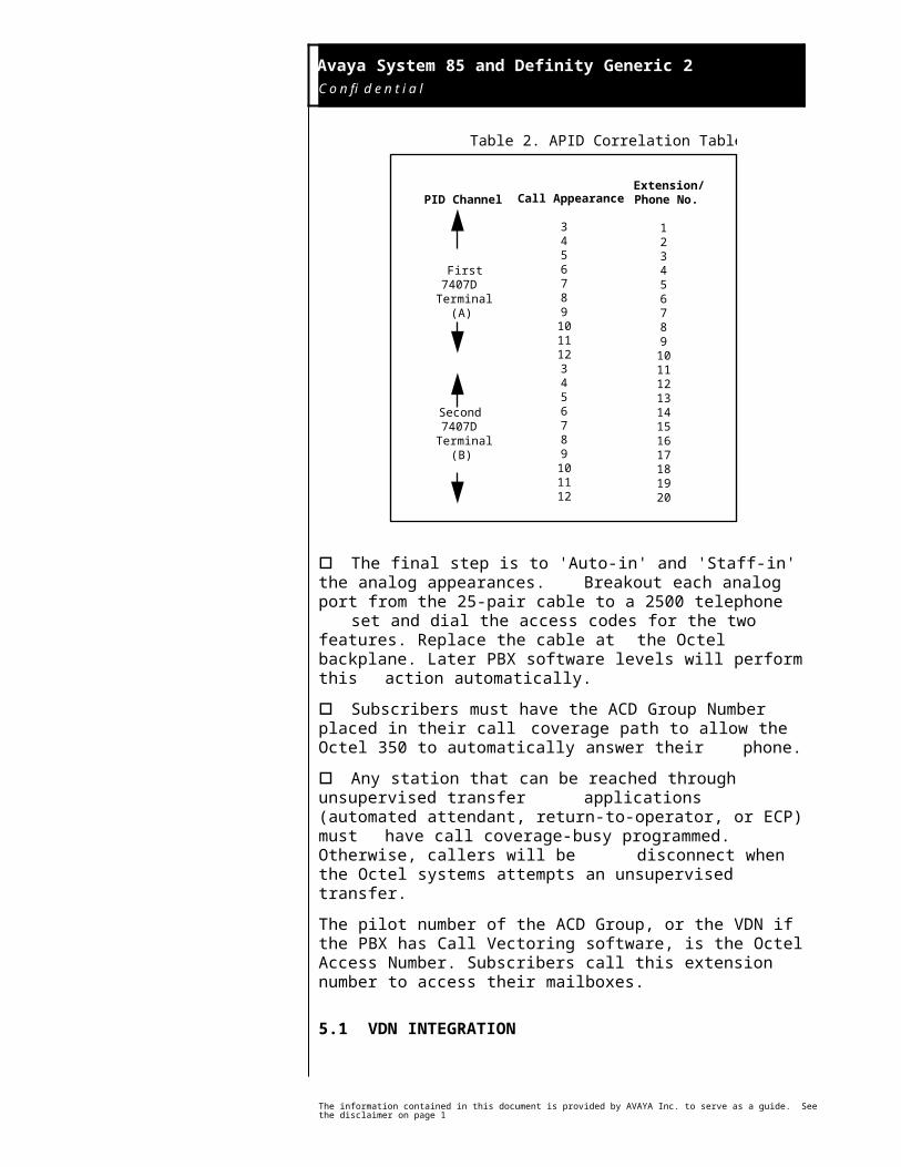
o Assign the Straight Line Sets (analog appearances) as call appearances on the 7407D terminals using PROC 052 WORD 1.
Each 7407D terminal can contain 10 appearances, members 3 through 12. Assign the analog appearances, alternating between the two 7407D
terminals. Refer to Table 2 for an example.
• Fields 1-5: Terminal Equipment Line Location = Enter equipment location of the 7407D terminal
• Field 6: Device Type = 0
• Field 7: Member = 3-12
• Field 8: Extension Number = Enter extension number of the appropriate Straight Line Set
• Field 9: Line Appearance Number = 1
• Field 10: Line Type = 0
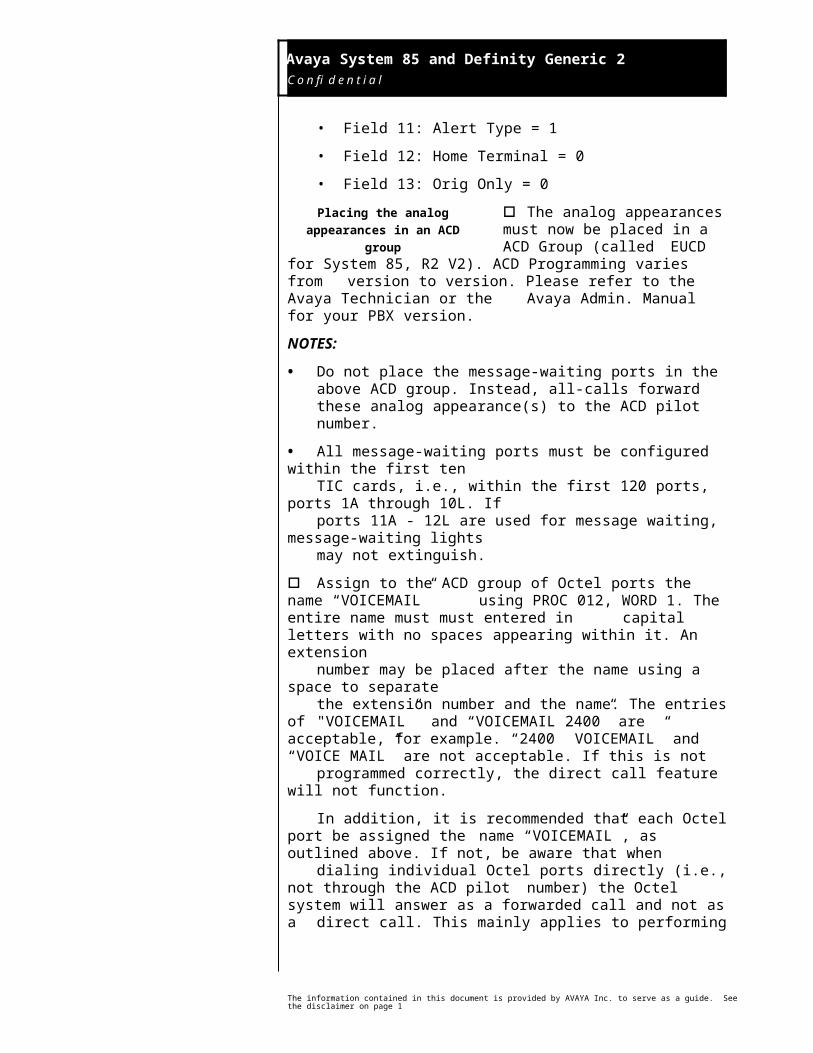
• Field 11: Alert Type = 1
• Field 12: Home Terminal = 0
The information contained in this document is provided by AVAYA Inc. to serve as a guide. See the disclaimer on page 1
Avaya System 85 and Definity Generic 2 C o n f i d e n t i a l
7
• Field 13: Orig Only = 0
o The analog appearances must now be placed in a ACD Group (called
EUCD for System 85, R2 V2). ACD Programming varies from version to version. Please refer to the Avaya Technician or the Avaya Admin. Manual for your PBX version.
NOTES:
• Do not place the message-waiting ports in the above ACD group. Instead, all-calls forward these analog appearance(s) to the ACD pilot number.
• All message-waiting ports must be configured within the first ten TIC cards, i.e., within the first 120 ports, ports 1A through 10L. If ports 11A - 12L are used for message waiting, message-waiting lights
may not extinguish.
o Assign to the ACD group of Octel ports the name “VOICEMAIL” using PROC 012, WORD 1. The entire name must must entered in capital letters with no spaces appearing within it. An extensionnumber may be placed after the name using a space to separatethe extension number and the name. The entries of "VOICEMAIL” and “VOICEMAIL 2400” are acceptable, for example. “2400 VOICEMAIL” and “VOICE MAIL” are not acceptable. If this is not programmed correctly, the direct call feature will not function.
In addition, it is recommended that each Octel port be assigned the name “VOICEMAIL”, as outlined above. If not, be aware that when dialing individual Octel ports directly (i.e., not through the ACD pilot number) the Octel system will answer as a forwarded call and not as a direct call. This mainly applies to performing port-to-port checks; day- to-day operation of the Octel 350 is not affected.
NOTE: No non-Octel extensions may have the partial or full name “VOICEMAIL” associated with it.
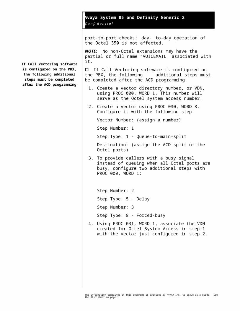
o If Call Vectoring software is configured on the PBX, the following additional steps must be completed after the ACD programming
1. Create a vector directory number, or VDN, using PROC 000, WORD 1. This number will serve as the Octel system access number.
2. Create a vector using PROC 030, WORD 3. Configure it with the following step:
Vector Number: (assign a number)
Step Number: 1
The information contained in this document is provided by AVAYA Inc. to serve as a guide. See the disclaimer on page 1
Placing the analog appearances in an ACD group
If Call Vectoring software is configured on the PBX, the
following additional steps must be completed after the ACD
programming
Avaya System 85 and Definity Generic 2 C o n f i d e n t i a l
8
Step Type: 1 - Queue-to-main-split
Destination: (assign the ACD split of the Octel ports)
3. To provide callers with a busy signal instead of queuing when all Octel ports are busy, configure two additional steps with PROC 000, WORD 1:
Step Number: 2
Step Type: 5 - Delay
Step Number: 3
Step Type: 8 - Forced-busy
4. Using PROC 031, WORD 1, associate the VDN created for Octel System Access in step 1 with the vector just configured in step 2.
PID Channel
First7407D
Terminal(A)
Second7407D
Terminal(B)
Call Appearance
3456789
1011123456789
101112
Extension/Phone No.
1234567891011121314151617181920
Table 2. APID Correlation Table
o The final step is to 'Auto-in' and 'Staff-in' the analog appearances. Breakout each analog port from the 25-pair cable to a 2500 telephone set and dial the access codes for the two features. Replace the cable at the Octel backplane. Later PBX software levels will perform this action automatically.
The information contained in this document is provided by AVAYA Inc. to serve as a guide. See the disclaimer on page 1
Avaya System 85 and Definity Generic 2 C o n f i d e n t i a l
9
o Subscribers must have the ACD Group Number placed in their call coverage path to allow the Octel 350 to automatically answer their phone.
o Any station that can be reached through unsupervised transfer applications (automated attendant, return-to-operator, or ECP) must have call coverage-busy programmed. Otherwise, callers will be disconnect when the Octel systems attempts an unsupervised transfer.
The pilot number of the ACD Group, or the VDN if the PBX has Call Vectoring software, is the Octel Access Number. Subscribers call this extension number to access their mailboxes.
5.1 VDN INTEGRATIONIntegration is provided for Vector Directory Numbers (VDNs) on Definity Generic 2 PBXs. Typical Applications that use VDNs are ACD
and DNIS. When calls to VDNs are routed through Call Vectoring to the Octel system, the greeting of the mailbox corresponding to the VDN is heard.
For VDN integration applications, to retain a VDN as the original-called party throughout the call vectoring steps associated with it, do not program VDN Display Override. This is programmed in PROC 031, WORD 1, FIELD 9, and when assigned to a VDN, might cause the VDN call ID to change during call vectoring process.
5.2 CONFIGURING THE SYSTEM 85/G2 TO INTEGRATE WITH MULTIPLE APIDS
Up to seven APIDs can be configured on the Octel 350 providing 140 integrated ports. For greater than two
APIDs (40 integrated ports), an ACP is required. Two additional 7407D terminals are required for each additional APID. Follow the PBX programming instructions previously described when the additional APIDs are installed. Care should be taken in the following areas:
• Assign the additional straight line sets (analog appearances) as call appearances on the 7407D terminals of the additional APID(s). Similar criteria apply for determining the number of call appearances on each 7407D terminal.
As an example, 32 integrated ports are required. The total number of ports associated with the second APID is 32 - 20 = 12.
• One ACD group is used when multiple APIDs are required. All integrated analog ports must be in the same group. (Do not place the message-waiting ports in the ACD group, however.) The
The information contained in this document is provided by AVAYA Inc. to serve as a guide. See the disclaimer on page 1
Integration is provided for Vector Directory Numbers
(VDNs) on Definity Generic 2 PBXs
Up to seven APIDs can be configured on the Octel
providing 140 integrated ports
Avaya System 85 and Definity Generic 2 C o n f i d e n t i a l
10
members of the group should be added in a specific order. Following is an example for an installation with three APIDs: the first ACD group member should be the first call appearance from the first APID, the second ACD group member should be the first call appearance on the second APID, the third ACD group member should be the first call appearance on the third APID, the fourth ACD group member should be the second line appearance on the first APID, etc.
6.0 CONFIGURING OCTEL 350o Menu 0 - First Time Set-up
• AT&T System 85 Special Message Waiting: Y - only if more than one port will be used for message waiting.
NOTE: Multiple message-waiting ports are recommended.
o Menu 1.1 - System Parameters
• Type of Switch: F - AT&T System 85
• ACP Used for Integration: answer Y if using ACP integration method. Answer N if using direct integration method.
o Menu 4.1 - Port Assignments
• A three- or four-digit number must be entered in the Menu 4.1 Extension/Phone No. field which is a combination of the two-digit link number and a one- or two-digit port number. The port numbers assigned for each APID should begin with 1, then 2, etc., up to 20. For each APID, begin again, using port number 1.
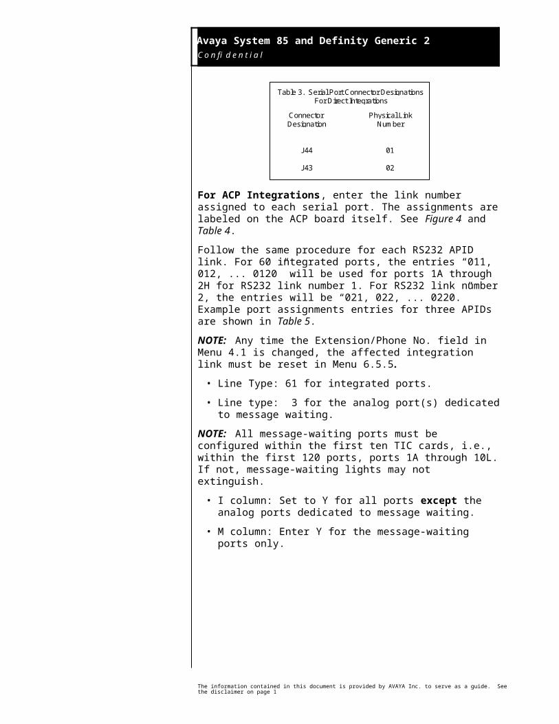
For direct integration, the physical link number corresponds with the actual connector on the distribution board used to make the connection. See Table 3 and Figure 2. The extension lines should be wired to the corresponding ATIC connections.
Table 3. Serial Port Connector DesignationsFor Direct Integrations
ConnectorDesignation
J44
J43
Physical LinkNumber
01
02
For ACP Integrations, enter the link number assigned to each serial port. The assignments are labeled on the ACP board itself. See Figure 4 and Table 4.
The information contained in this document is provided by AVAYA Inc. to serve as a guide. See the disclaimer on page 1
Configuring the Octel 350 system management menus
Avaya System 85 and Definity Generic 2 C o n f i d e n t i a l
11
Follow the same procedure for each RS232 APID link. For 60 integrated ports, the entries “011, 012, ... 0120” will be used for ports 1A through 2H for RS232 link number 1. For RS232 link number 2, the entries will be “021, 022, ... 0220.” Example port assignments entries for three APIDs are shown in Table 5.
NOTE: Any time the Extension/Phone No. field in Menu 4.1 is changed, the affected integration link must be reset in Menu 6.5.5.
• Line Type: 61 for integrated ports.
• Line type: 3 for the analog port(s) dedicated to message waiting.
NOTE: All message-waiting ports must be configured within the first ten TIC cards, i.e., within the first 120 ports, ports 1A through 10L. If not, message-waiting lights may not extinguish.
• I column: Set to Y for all ports except the analog ports dedicated to message waiting.
• M column: Enter Y for the message-waiting ports only.
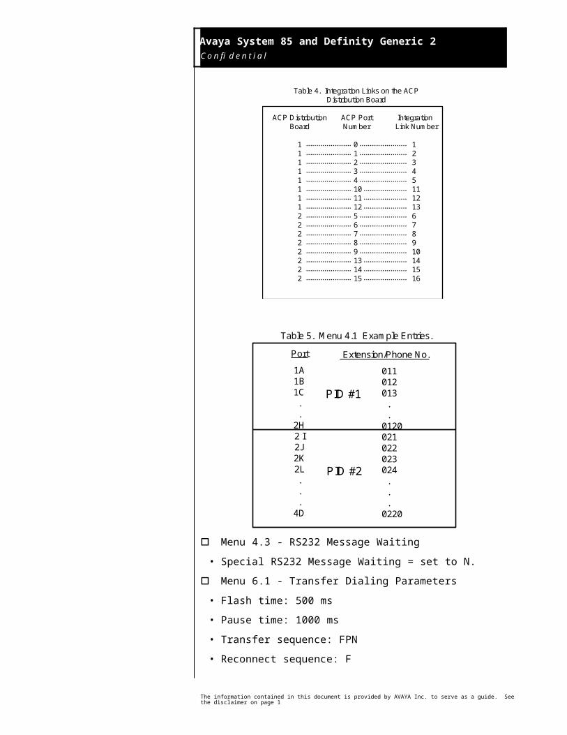
Table 4. Integration Links on the ACPDistribution Board
ACP DistributionBoard
1111111122222222
ACP Port Number
0 1 2 3 4 10 11 12 5 6 7 8 9 13 14 15
IntegrationLink Number
1 2 3 4 5 11 12 13 6 7 8 9 10 14 15 16
...................... .......................
...................... .......................
...................... .......................
...................... .......................
...................... .......................
...................... .....................
...................... .....................
...................... .....................
...................... .......................
...................... .......................
...................... .......................
...................... .......................
...................... .......................
...................... .....................
...................... .....................
...................... .....................
The information contained in this document is provided by AVAYA Inc. to serve as a guide. See the disclaimer on page 1
Avaya System 85 and Definity Generic 2 C o n f i d e n t i a l
12
Table 5. Menu 4.1 Example Entries.
Port
1A 1B 1C . . 2H 2 I 2J 2K 2L . . . 4D
Extension/Phone No.
011 012 013 . . 0120 021 022 023 024 . . . 0220
PID #1
PID #2
o Menu 4.3 - RS232 Message Waiting
• Special RS232 Message Waiting = set to N.
o Menu 6.1 - Transfer Dialing Parameters
• Flash time: 500 ms
• Pause time: 1000 ms
• Transfer sequence: FPN
• Reconnect sequence: F
NOTE: Verify the dialing sequences on the PBX.
o Menu 6.2 - In-Band Integration
• Dialing Sequence to Activate Message Waiting: “(Leave Word Calling Activate Code)PNP”. For example, 20PNP, where “20” is the feature code used to activate message waiting.
• Dialing Sequence to Deactivate Message Waiting: “(Leave Word Calling Deactivate Code)PNP”. For example, 21PNP, where “21” is the feature code used to deactivate message waiting.
NOTE: Feature codes are configurable on the PBX. Be sure to ask the Telecom Manager for the Leave Word Calling Activate/ Deactivate Codes on the System 85/Definity Generic 2.
• All other entries should be left blank or remain at the default setting.
o Menu 6.3 - Define CPU Serial Channels
• For each configurable serial channel (channels 1 and 2) to be used for direct integration, assign channel type 3 - Direct Integration. When
The information contained in this document is provided by AVAYA Inc. to serve as a guide. See the disclaimer on page 1
Avaya System 85 and Definity Generic 2 C o n f i d e n t i a l
13
“Direct Integration” is chosen for a serial channel configuration, you will need to program menu 6.5.2 for each link. (See bullet on Menu 6.5.)
• If ACP integration is being used, configure the integration links in Menu 6.5. ACP integration links do not use CPU serial channels, and therefore, do not require programming in Menu 6.3.
NOTES:
• Channels 3 and 4 are not configurable.
• The Octel 350 must be rebooted to apply any changes to serial channel parameters.
o Menu 6.5 - Integration Link Management
• In menu 6.5, for each integration link select “F - PBX Integration Device - AT&T S/85”. This will create the following default parameters:
Baud Rate: 9600Number of Data Bits: 7Number of Stop Bits: 2Parity: Odd parityXON/XOFF: IgnoreCarrier Detect: Carrier Detect Not UsedExtension to Check SMDI Message Waiting: blank
Retain all of these default parameters.
NOTE: After any changes are made in Menu 6.5.2, reset the affected integration link(s) using Menu 6.5.5.
o Menu 8/9.1 - Mailbox Profile
• “Subscriber’s Extension Number”: If the subscriber is allowed to have message waiting, enter his or her phone number in this entry.
• “Link Number”: Enter the physical link number which is associated with the subscriber’s PBX.
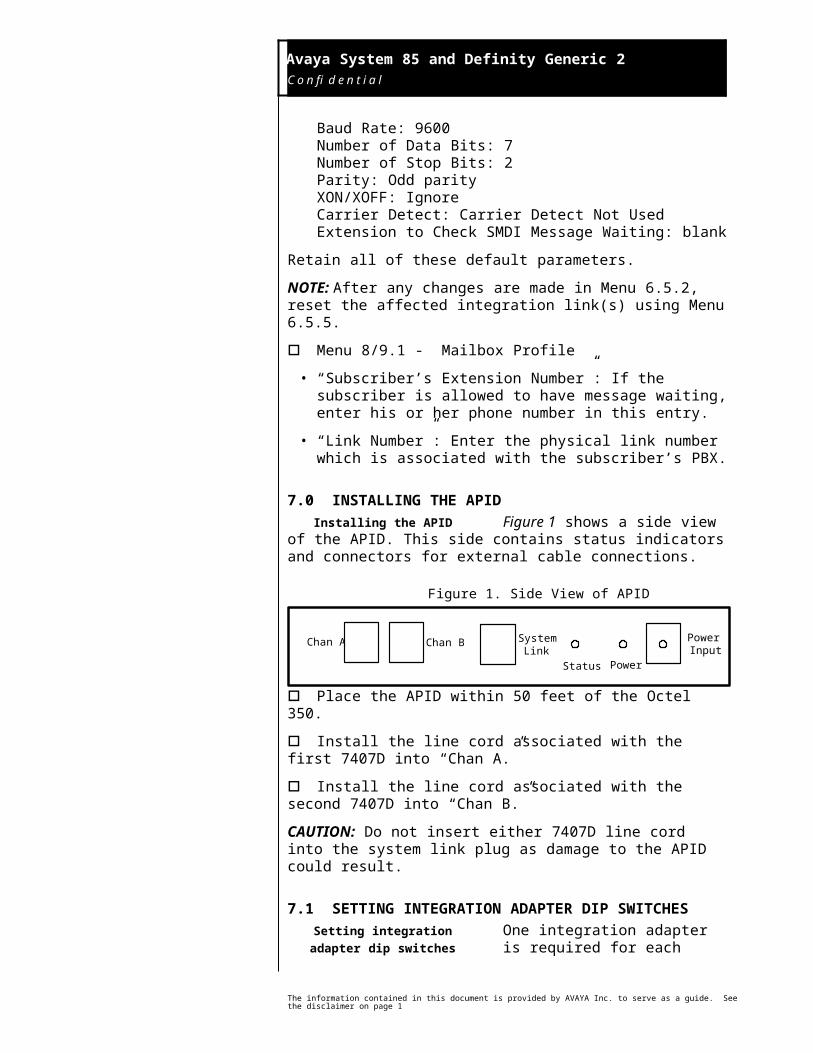
7.0 INSTALLING THE APIDFigure 1 shows a side view of the
APID. This side contains status indicators and connectors for external cable connections.
The information contained in this document is provided by AVAYA Inc. to serve as a guide. See the disclaimer on page 1
Installing the APID
Avaya System 85 and Definity Generic 2 C o n f i d e n t i a l
14
Chan A Chan B SystemLink
PowerInput
Status Power
Figure 1. Side View of APID
o Place the APID within 50 feet of the Octel 350.
o Install the line cord associated with the first 7407D into “Chan A.”
o Install the line cord associated with the second 7407D into “Chan B.”
CAUTION: Do not insert either 7407D line cord into the system link plug as damage to the APID could result.
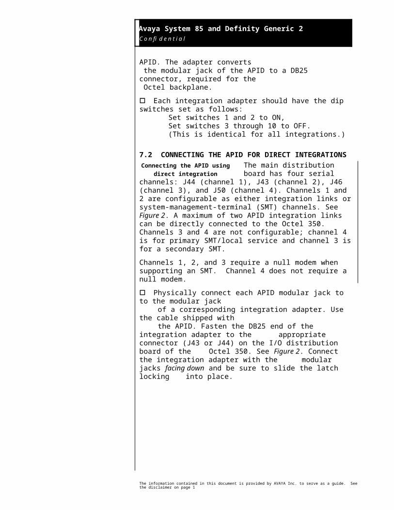
7.1 SETTING INTEGRATION ADAPTER DIP SWITCHESOne integration adapter is required for each APID. The adapter converts
the modular jack of the APID to a DB25 connector, required for the Octel backplane.
o Each integration adapter should have the dip switches set as follows:Set switches 1 and 2 to ON,Set switches 3 through 10 to OFF.(This is identical for all integrations.)
7.2 CONNECTING THE APID FOR DIRECT INTEGRATIONSThe main distribution board has four serial channels: J44 (channel 1), J43
(channel 2), J46 (channel 3), and J50 (channel 4). Channels 1 and 2 are configurable as either integration links or system-management-terminal (SMT) channels. See Figure 2. A maximum of two APID integration links can be directly connected to the Octel 350. Channels 3 and 4 are not configurable; channel 4 is for primary SMT/local service and channel 3 is for a secondary SMT.
Channels 1, 2, and 3 require a null modem when supporting an SMT. Channel 4 does not require a null modem.
o Physically connect each APID modular jack to to the modular jack of a corresponding integration adapter. Use the cable shipped with the APID. Fasten the DB25 end of the integration adapter to the appropriate connector (J43 or J44) on the I/O distribution board of the Octel 350. See Figure 2. Connect the integration adapter with the modular jacks facing down and be sure to slide the latch locking into place.
The information contained in this document is provided by AVAYA Inc. to serve as a guide. See the disclaimer on page 1
Setting integration adapter dip switches
Connecting the APID using direct integration
Avaya System 85 and Definity Generic 2 C o n f i d e n t i a l
15
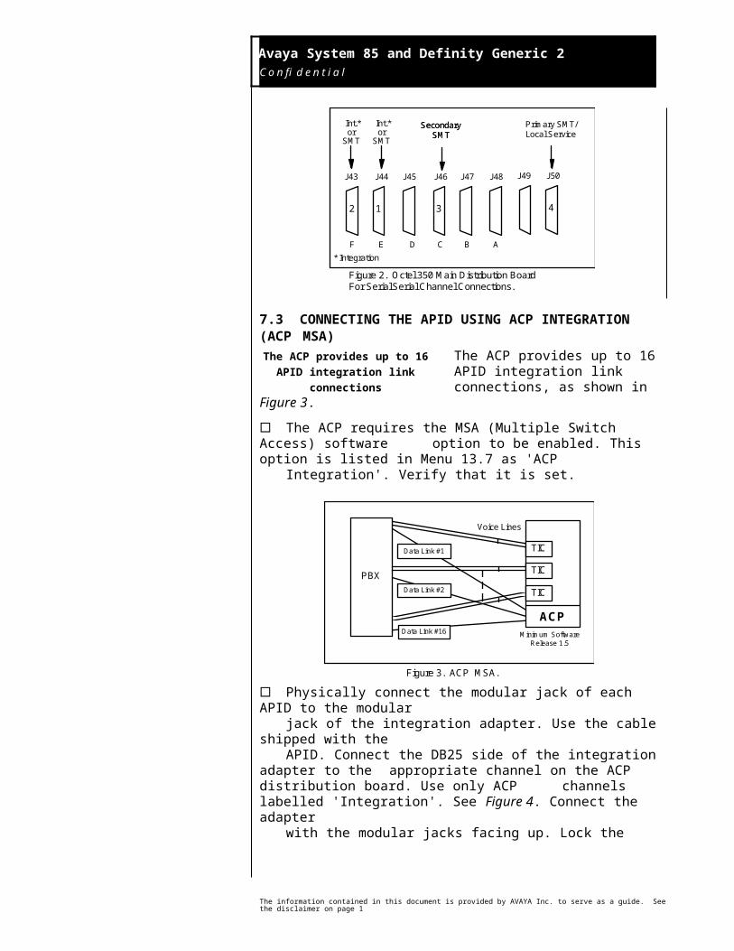
Figure 2. Octel 350 Main Distribution BoardFor Serial Serial Channel Connections.
2 1 3 4
J43 J44 J45 J46 J47 J48 J49 J50
F E D C B A
Int.*or
SMT
Int.*or
SMT
Secondary SMT
Primary SMT/Local Service
Secondary SMT
* Integration
7.3 CONNECTING THE APID USING ACP INTEGRATION (ACP MSA)
The ACP provides up to 16 APID integration link connections, as shown
in Figure 3.
¨ The ACP requires the MSA (Multiple Switch Access) software option to be enabled. This option is listed in Menu 13.7 as 'ACP Integration'. Verify that it is set.
Data Link #1
Data Link #2
Data Link #16
Voice Lines
Minimum SoftwareRelease 1.5
Figure 3. ACP MSA.
ACP
TIC
TIC
TIC
PBX
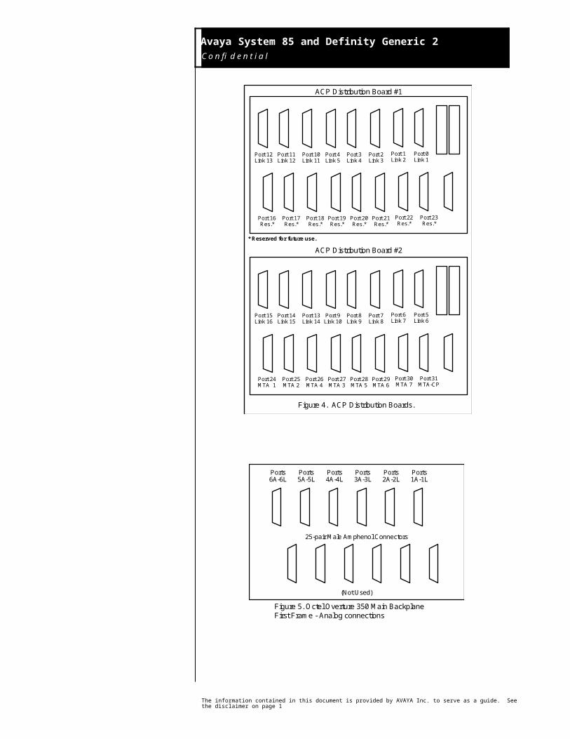
¨ Physically connect the modular jack of each APID to the modularjack of the integration adapter. Use the cable shipped with theAPID. Connect the DB25 side of the integration adapter to the appropriate channel on the ACP distribution board. Use only ACP channels labelled 'Integration'. See Figure 4. Connect the adapterwith the modular jacks facing up. Lock the DB25 connectors inplace by moving the slide latch down.
7.4 POWERING THE APIDo Insert the power cord into the
power input receptacle and into a 110 Vac wall outlet. The green status LED indicator should light for approximately 10 seconds. After the light
The information contained in this document is provided by AVAYA Inc. to serve as a guide. See the disclaimer on page 1
The ACP provides up to 16 APID integration link connections
Powering the APID
Avaya System 85 and Definity Generic 2 C o n f i d e n t i a l
16
goes out, the APID is initialized and functional. The status LED flashes every time the APID processes a call. The green power LED indicator will remain activated as long as there is acceptable power to the APID.
7.5 CONNECTING THE ANALOG CHANNELSEach Analog TIC supports 12 ports.
Each Analog TIC connects to the switch via a single cable. The first port uses the first pair of connectors (1,26), the second port uses the second pair (2,27), etc.
¨ Physically connect the lines used for the voice path between the switch and the Octel 350. The voice lines are connected to the switch using DB25 cables with a right-angle terminal which connects to the main backplane on the Octel frames. See Figures 5 and 6.
ACP Distribution Board #1
ACP Distribution Board #2
* Reserved for future use.
Figure 4. ACP Distribution Boards.
Port 15Link 16
Port 14Link 15
Port 13Link 14
Port 9Link 10
Port 8Link 9
Port 7Link 8
Port 6Link 7
Port 5Link 6
Port 24MTA 1
Port 25MTA 2
Port 26MTA 4
Port 27MTA 3
Port 28MTA 5
Port 29MTA 6
Port 30MTA 7
Port 31MTA-CP
Port 12Link 13
Port 11Link 12
Port 10Link 11
Port 4Link 5
Port 3Link 4
Port 2Link 3
Port 1Link 2
Port 0Link 1
Port 16Res.*
Port 17Res.*
Port 18Res.*
Port 19Res.*
Port 20Res.*
Port 21Res.*
Port 22Res.*
Port 23Res.*
The information contained in this document is provided by AVAYA Inc. to serve as a guide. See the disclaimer on page 1
Connecting the analog channels
Avaya System 85 and Definity Generic 2 C o n f i d e n t i a l
17
Ports6A-6L
Ports5A-5L
Ports4A-4L
Ports3A-3L
Ports2A-2L
Ports1A-1L
25-pair Male Amphenol Connectors
(Not Used)
Figure 5. Octel Overture 350 Main BackplaneFirst Frame - Analog connections
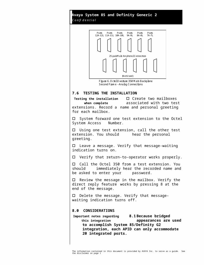
Ports12A-12L
Ports11A-11L
Ports10A-10L
Ports9A-9L
Ports8A-8L
Ports7A-7L
25-pair Male Amphenol Connectors
(Not Used)
Figure 6. Octel Overture 350 Main BackplaneSecond Frame - Analog Connections
7.6 TESTING THE INSTALLATIONo Create two mailboxes associated with two test extensions. Record a
name and personal greeting for each mailbox.
o System forward one test extension to the Octel System Access Number.
o Using one test extension, call the other test extension. You should hear the personal greeting.
o Leave a message. Verify that message-waiting indication turns on.
o Verify that return-to-operator works properly.
o Call the Octel 350 from a test extension. You should immediately hear the recorded name and be asked to enter your password.
The information contained in this document is provided by AVAYA Inc. to serve as a guide. See the disclaimer on page 1
Testing the installation when complete
Avaya System 85 and Definity Generic 2 C o n f i d e n t i a l
18
o Review the message in the mailbox. Verify the direct reply feature works by pressing 8 at the end of the message.
o Delete the message. Verify that message-waiting indication turns off.
8.0 CONSIDERATIONS 8.1 Because bridged appearances
are used to accomplish System 85/Definity G2 integration, each APID can only accommodate 20 integrated ports.
8.2 Station call forwarding to a station that is also station call forwarded will result in a ring-no-answer. It is recommended that all stations use either Call Coverage or station call forwarding to the Octel 350 only.
8.3 The attendant console cannot overflow to the Octel 350.
8.4 Octel Sales Engineering must be contacted regarding DCS sites. R2V4 software is required. Without Call Vectoring software, all integration features are supported except Call Coverage for the remote sites. Users on the remote PBXs must use all-calls forwarding to achieve personal greeting.
For R2V5 PBXs with Call Vectoring software, full integration is provided for remote sites, including Call Coverage to personal greeting. Each remote site will have a unique Octel system access number. In this configuration, supervised transfers can be supported for either the main PBX or the remote sites, but not both.
Note that the use of Automatic Alternate Routing software on the PBXs which reroutes DCS calls over the public network when all tie trunks are busy will interfere with integration.
8.5 Extensions on the PBX can be up to five digits long. Therefore, to support integration, the maximum number of digits in a mailbox can be five.
8.6 When a users’ message-waiting lights come on and the Leave Word Calling (LWC) feature is being used exclusively by theOctel system, users will only need to call the Octel 350 for their messages.
If the LWC feature is being used by the Octel 350 and other sources (that is message center and station users), then users without display terminals must contact their designated message retriever to determine the source of their message-waiting light.
CAUTION: Users with display terminals and message retrievers must not delete any Octel message on their display. This allows the Octel 350 to turn off the message-waiting light when voice messages are reviewed.
The information contained in this document is provided by AVAYA Inc. to serve as a guide. See the disclaimer on page 1
Important notes regarding this integration
Avaya System 85 and Definity Generic 2 C o n f i d e n t i a l
19
8.7 Octel recommends using ports from analog circuit packs SN228 or SN229B, as these circuit packs provide open-loop disconnect signals to Octel ports, thus allowing for faster port hang-up. Circuit packs SN229 do not provide the open-loop disconnect, causing Octel ports to have to rely on silence detection for disconnect.
8.8 DCS is Avaya's PBX networking package. In a DCS environment, subscribers on the remote nodes may not have the same integration feature functionality as those on the hub node. In general, all integration features are supported. Call Coverage support on the remote nodes is dependant on the type of switch and software as follows:
• If they are on a G3 V2 or higher system, the Remote Call Coverage feature is standard and allows coverage to personal greeting for Busy and RNA conditions.
• If they are on a G2, they must call cover to a VDN that routes the call to the hub system. This allows coverage to personal greeting on Busy and RNA conditions. VDN software is an optional package on the G2. Without VDN S/W, they will be limited to station call forwarding All Calls only.
• If they are on a System 75 or G1 system, they are limited to station call forwarding All Calls only.
• In all cases MWI is supported to the remote hubs over a DCS network.
NOTE: G3i V1 7.0 with DCS is not supported. The display
field shifts two characters on the PBX side which interferes with integration. In addition, V1 software does not support call Coverage to a VDN.
The information contained in this document is provided by AVAYA Inc. to serve as a guide. See the disclaimer on page 1
Important notes regarding this integration
Avaya System 85 and Definity Generic 2 C o n f i d e n t i a l
20
9.0 APPENDIX AProgramming the System 85/Definity Generic 2 Using theAvaya Centralized System Manager (CSM) Terminal
The following System 85/Definity Generic 2 programming instructions are applicable when using the Avaya CSM terminal. This device allows creation of the same translations as the SMT or MAAP but in a menu-driven format.
o Create each appearance to be connected to an Octel port as a Straight Line Set (SLS). See Figures 1 and 2.
SLSSet I.D.: <extension #> Set Type: 2500Set Mount: <blank> Set Color : <blank> Locale: <blank>
Equip. Loc.: <enter Equip.Loc. of each SLS>
Extension No.: <extension#> Call Appearance: 01 Alert Type: 0 Homed? y AMW? n
Analog Type: <blank>Special Equipment/Adjuncts:
Spkrphone? n Price Elements 1-4: <all blank>Headset? n
Abbreviated Dialing:A List Type : <blank>B List Type:: <blank>System List Access? n
Page 1 of 1
Figure 1.
The information contained in this document is provided by AVAYA Inc. to serve as a guide. See the disclaimer on page 1
Avaya System 85 and Definity Generic 2 C o n f i d e n t i a l
21
EXTENSIONLast Service Request Number: <blank>Date: <blank>State: <balnk>Set Type: <blank>Extension No.: <ext.#>
Analog: n
Class of Service: <normal COS> This ext hunts to ext no.: <blank, if ACD not used>aux ANI? <blank> LWC Destination: <blank> AP: #: <blank> Audix Machine Number: <blank>Extn is in Call Pickup group with extn #: <blank> OR Call Pickup Group No.: <blank>Extn is in Call Coverage group with extn #. <blank> OR Call Cov. Grp: <blank> Controlled Restriction Group: <blank>
Page 1 of 4Page 2, 3, 4 <blank>
Figure 2.
o Repeat for each SLS appearance.
NOTE: If the SLSs have previously been created (for example, for interfaced/WooBox installation) as pure analog stations, an extension menu will have been created, but not a SLS menu. To change from analog to SLS, delete the Equip. Loc.: entry in the extension menu and create a SLS menu where the ELL is re-entered.
o Use the following menus to define the two General Purpose Ports. See Figures 3 and 4.
The information contained in this document is provided by AVAYA Inc. to serve as a guide. See the disclaimer on page 1
Avaya System 85 and Definity Generic 2 C o n f i d e n t i a l
22
IDT Set I.D.: <extension# of 7407D< Set Type: 7407DSet Mount: <blank> Set Color: <blank> Locale: <blank> Equip. Loc: <enter Equip. Loc. for 7407D>
Display Module: yOrigination: 2 Termination: 2 Lock/unlock? n LWC Global Retrieval? n
DTDM? n
Special Equipment/Adjuncts: Spkrphone? n Price Elements 1-4: <all blank> Headset? n
Abbreviated Dialing: A List Type: <blank> Personal List Size: <blank> B List Type: <blank> System List Access? n
Page 1 of 2
Set I.D.: <extension # of 7407D> Set Type: 7407D03) CALL<1st SLS ext. #> xxxxxxxx 08)04) <repeat for each SLS> 09)05) 10)06) 11)07) 12)
13) SAC 14) PROG
Display Buttons:15)-36) AD 04) TIMR 05) RMSG 06) NEXT 07) DELPage 2 of 2
Figure 3.
The information contained in this document is provided by AVAYA Inc. to serve as a guide. See the disclaimer on page 1
Avaya System 85 and Definity Generic 2 C o n f i d e n t i a l
23
EXTENSIONLast Service Request Number: <blank>Date: <blank>State: <balnk>Set Type: <blank>Extension No.: <ext.#>
Analog: n
Class of Service: <normal COS> This ext hunts to ext ext no.: <blank>aux ANI? <blank> LWC Destination: <blank> AP: #: <blank> Audix Machine Number: <blank>Extn is in Call Pickup group with extn #: <blank> OR Call Pickup Group No.: <blank>Extn is in Call Coverage group with extn #. <blank> OR Call Cov. Grp: <blank> Controlled Restriction Group: <blank>
Page 1 of 4Page 2, 3, 4 <blank>
Figure 4.
o The SLSs will appear as call appearances on one or the other phone, but not on both. Refer to the main body of this note for more information.
©2001 AVAYA Inc. All rights reserved. All trademarks identified by the ®, SM and TM are registered trademarks, servicemarks or trademarks respectively. All other trademarks are properties of their respective owners. The above information is based on knowledge available at the time of publication and is subject to change without notice. Printed in U.S.A.
AVAYA Inc.1001 Murphy Ranch Road
Milpitas, CA 95035-7912
(408) 321-2000
http://www.avaya.com
The information contained in this document is provided by AVAYA Inc. to serve as a guide. See the disclaimer on page 1