hyload.com · web viewsection 07 13 00. sheet membrane waterproofing. make sure you display...
TRANSCRIPT

SECTION 07 13 00SHEET MEMBRANE WATERPROOFING
Make sure you display hidden notes in Microsoft Word to see notes to specifier.
PART 1 GENERAL
1.1 SECTION INCLUDES
A. Sheet Membrane Waterproofing, Vertical Below Grade.
B. Sheet Membrane Waterproofing, Horizontal.
1.2 RELATED SECTIONS
A. Section 31 23 16.13 - Trenching
B. Section 33 46 19.13 - Underslab Drainage Piping
C. Section 33 49 23 - Storm Drainage Water Retention Structures
D. Section 03 30 00 - Cast-in-Place Concrete
E. Section 22 11 13 - Facility Water Distribution Piping
1.3 REFERENCES
A. ASTM C 272 - Test Method for Water Absorption of Core Materials for Structural Sandwich Constructions
B. ASTM C 518 - Test method for Steady-State Heat Flux Measurements and Thermal Transmission Properties by Means of the Heat Flow Meter Apparatus
C. ASTM C 578 - Specification for Preformed, Cellular Polystyrene Thermal Insulation
D. ASTM D 1621 - Test for Compressive Properties of Rigid Cellular Plastics
E. ASTM D 4263 - Test Method for Indicating Moisture in Concrete by the Plastic Sheet Method
F. ASTM D 4491 - Test Methods for Water Permeability of Geotextiles by Permittivity
G. ASTM D 4716 - Test Method for Constant Head Hydraulic Transmissivity (In-Place Flow) of Geotextiles and Geotextile Related Products
H. ASTM D 4833 - Test Method for Index Puncture Resistance of Geotextiles, Geomembranes, and Related Products
I. ASTM D 5957 - Guide for Flood Testing Horizontal Waterproofing Installations
J. ASTM E 96 - Tests for Water Vapor Transmission of Materials in Sheet Form
1.4 SYSTEM DESCRIPTION
A. Single-ply application of waterproofing membrane sheets bonded together with hot air welds or structural sealant.
07 13 00-1

1. System shall be:a. Self-adhered to a vertical surface.b. Adhesive mastic to a vertical surface.c. Loose laid onto an adhesive grid over a horizontal surface.
2. System designed to limit lateral movement of water in event of membrane damage without use of additional installed components.
3. Membranes are highly resistant to acids, bases, oils, greases, petroleum products, root penetration, and organic growth such as molds and algae. Membranes are UV stable, impervious to standing water, and not effected by contact with asphalt or coal tar
B. Two-ply application of waterproofing membrane sheets bonded together with hot air welds or structural sealant.1. System shall be:
a. Self-adhered to a vertical surface.b. Self-adhered over a horizontal surface.
2. System designed to limit lateral movement of water in event of membrane damage without use of additional installed components.
3. Membranes are highly resistant to acids, bases, oils, greases, petroleum products, root penetration, and organic growth such as molds and algae. Membranes are UV stable, impervious to standing water, and not effected by contact with asphalt or coal tar
1.5 SUBMITTALS
A. Submit under provisions of Section 01 30 00 - Administrative Requirements.
B. Product Data: Manufacturer's data sheets on each product to be used, including:1. Preparation instructions and recommendations.2. Storage and handling requirements and recommendations.3. Application procedures.
C. Shop Drawings:1. Submit shop drawings showing general layout, seaming, anchoring sizes and types,
membrane thickness, and other similar detailed information necessary to fully describe application.
2. Include:a. Location of penetrationsb. Perimeter and penetration detailsc. Sheet layout and sized. Number of flashing rolls by width
3. Show adjacent or related portions of Work in a complete manner.4. Coordinate submittal with submittals of related portions of Work:
D. Verification Samples: For each membrane material, preformed three-dimensional shape, insulation board, and drainage board product specified, two samples, minimum size 6 inches (150 mm) square, representing actual product.
E. Manufacturer's Certificates: Certify products meet or exceed specified requirements.
F. Closeout Submittals: Submit manufacturer warranty and ensure forms have been completed in Owner's name and registered with manufacturer.
1.6 QUALITY ASSURANCE
A. Manufacturer Qualifications: Company specializing in manufacture of sheet membrane waterproofing system with not less than 10 years documented experience.
07 13 00-2
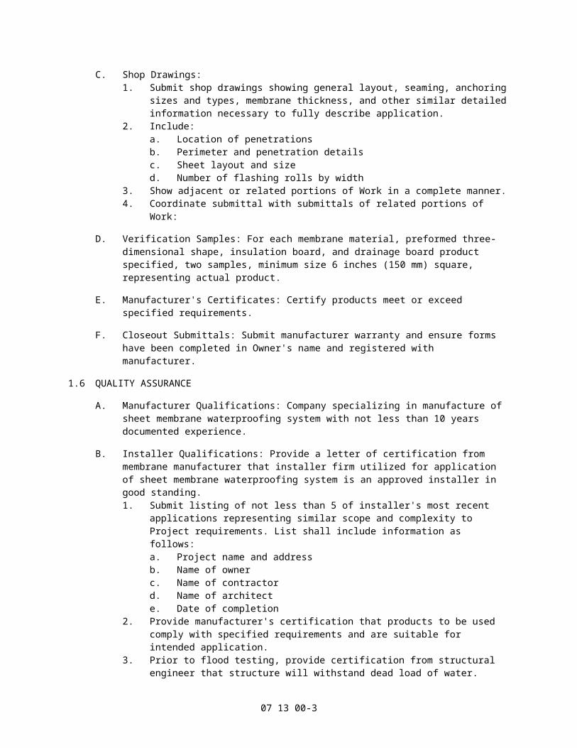
B. Installer Qualifications: Provide a letter of certification from membrane manufacturer that installer firm utilized for application of sheet membrane waterproofing system is an approved installer in good standing.1. Submit listing of not less than 5 of installer's most recent applications representing
similar scope and complexity to Project requirements. List shall include information as follows:a. Project name and addressb. Name of ownerc. Name of contractord. Name of architecte. Date of completion
2. Provide manufacturer's certification that products to be used comply with specified requirements and are suitable for intended application.
3. Prior to flood testing, provide certification from structural engineer that structure will withstand dead load of water.
C. Pre-Application Conference:1. Schedule a conference to be held on-site in advance of ordering materials and
beginning application of waterproofing, but in no case less than 30 days before application of waterproofing. Provide not less than 72 hours advance notification to attendees, Owner, and Architect.
2. Conference attendees shall include Owner, Architect, Contractor, waterproofing installer, a representative of waterproofing manufacturer, and representatives of other trades whose work may interface with or affect waterproofing application.
3. Topics to be discussed at conference shall include:a. A review of Contract Documents and accepted shop drawings shall be made. If
conflicts exist between manufacturer's specifications and Contract Documents, these differences shall be defined and resolved. Consult waterproofing manufacturer's representative to assist in resolving issues.
b. Establish trade-related work schedules and appropriate trade sequencing, including timely installation of equipment and penetrations to avoid or limit traffic on membrane waterproofing.
c. Review areas to receive different waterproofing systems and transition between various systems to be used.
d. Construction schedules and work methods shall be reviewed to prevent damage to waterproofing, including provisions for installation of temporary traffic paths or walkways for protection of finished waterproofing system.
e. Weather conditions and working temperature criteria shall be reviewed.f. Establish and review provisions for on-site monitoring after waterproofing
application is complete to assure that finished waterproofing application is not damaged by other trades. Establish provisions for payment for repairs in event that damage does occur.
4. Pre-construction conference and inspection shall serve to clarify Contract Documents, application requirements and what work shall be completed before application can begin.a. If waterproofing applicator or representative of waterproofing manufacturer
discovers problems during inspection of substrates, a second pre-application shall be held to verify that corrective measures have been taken.
5. Prepare and submit to parties in attendance, Architect, and Owner a written report of pre-installation conference. Report shall be submitted within 3 days following conference.
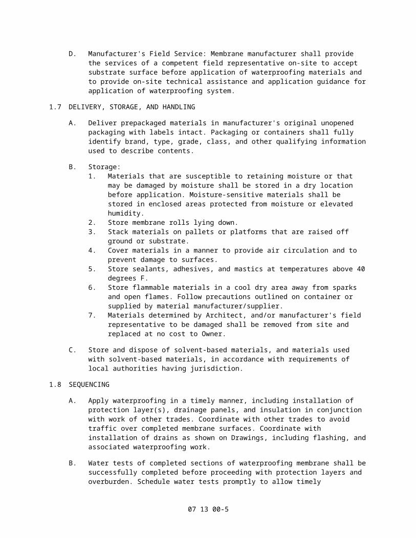
D. Manufacturer's Field Service: Membrane manufacturer shall provide the services of a competent field representative on-site to accept substrate surface before application of waterproofing materials and to provide on-site technical assistance and application guidance for application of waterproofing system.
07 13 00-3

1.7 DELIVERY, STORAGE, AND HANDLING
A. Deliver prepackaged materials in manufacturer's original unopened packaging with labels intact. Packaging or containers shall fully identify brand, type, grade, class, and other qualifying information used to describe contents.
B. Storage:1. Materials that are susceptible to retaining moisture or that may be damaged by
moisture shall be stored in a dry location before application. Moisture-sensitive materials shall be stored in enclosed areas protected from moisture or elevated humidity.
2. Store membrane rolls lying down.3. Stack materials on pallets or platforms that are raised off ground or substrate.4. Cover materials in a manner to provide air circulation and to prevent damage to
surfaces.5. Store sealants, adhesives, and mastics at temperatures above 40 degrees F.6. Store flammable materials in a cool dry area away from sparks and open flames.
Follow precautions outlined on container or supplied by material manufacturer/supplier.
7. Materials determined by Architect, and/or manufacturer's field representative to be damaged shall be removed from site and replaced at no cost to Owner.
C. Store and dispose of solvent-based materials, and materials used with solvent-based materials, in accordance with requirements of local authorities having jurisdiction.
1.8 SEQUENCING
A. Apply waterproofing in a timely manner, including installation of protection layer(s), drainage panels, and insulation in conjunction with work of other trades. Coordinate with other trades to avoid traffic over completed membrane surfaces. Coordinate with installation of drains as shown on Drawings, including flashing, and associated waterproofing work.
B. Water tests of completed sections of waterproofing membrane shall be successfully completed before proceeding with protection layers and overburden. Schedule water tests promptly to allow timely installation of protection layers.
1.9 PROJECT CONDITIONS
A. Maintain environmental conditions (temperature, humidity, and ventilation) within limits recommended by manufacturer for optimum results. Do not install products under environmental conditions outside manufacturer's absolute limits.1. Waterproofing materials and components shall not be applied unless correct solvent,
adhesive, heat welding, or application temperature can be maintained. If proper application temperatures cannot be maintained, application shall cease.
2. Do not apply waterproofing if precipitation of any kind is occurring or is imminent. Materials shall not be applied if liquid moisture, snow, or ice is present on substrate.
1.10 WARRANTY
A. Manufacturer's Single-Ply Warranty:1. Provide a manufacturer's membrane only. Warranty shall be limited to performance of
waterproofing membrane for a period of 10 years from Date of Substantial Completion.
2. Provide a manufacturer's membrane only. Warranty shall be limited to performance of waterproofing membrane for a period of 15 years from Date of Substantial Completion.
3. Provide a manufacturer's labor and material. Warranty shall include repair of leaks in
07 13 00-4
waterproofing membrane resulting from defects in membrane or workmanship for a period of 10 years from Date of Substantial Completion.
4. Provide a manufacturer's labor and material. Warranty shall include repair of leaks in waterproofing membrane resulting from defects in membrane or workmanship for a period of 15 years from Date of Substantial Completion.
B. Manufacturer's Two-Ply Warranty:1. Provide a manufacturer's membrane only. Warranty shall be limited to performance of
waterproofing membrane for a period of 20 years from Date of Substantial Completion.
2. Provide a manufacturer's labor and material. Warranty shall include repair of leaks in waterproofing membrane resulting from defects in membrane or workmanship for a period of 20 years from Date of Substantial Completion.
C. Contractor's Warranty:1. Provide a workmanship warranty for not less than two-years commencing from Date
of Substantial Completion.2. Work related to waterproofing membrane, flashing, or metal work found to be
defective or not in compliance with contract documents shall be removed and replaced at no cost to Owner. Obligation of warranty shall run directly to Owner with a copy to membrane manufacturer.
PART 2 PRODUCTS
2.1 MANUFACTURERS
A. Acceptable Manufacturer: Hyload, which is located at: 5020 Enterprise Pkwy.; Seville, OH 44273; Toll Free Tel: 800-457-4056; Tel: 330-769-3546 ; Fax: 330-769-4153; Email:request info ([email protected]); Web:www.hyload.com
B. Substitutions: Not permitted.
C. Requests for substitutions will be considered in accordance with provisions of Section 01 60 00 - Product Requirements.
2.2 PRODUCTS, GENERAL
A. Materials shall be products of a single manufacturer or items standard with manufacturer of sheet membrane waterproofing system. Provide primers and other secondary materials that are produced or are specifically recommended by manufacturer of membrane waterproofing system to ensure compatibility.
2.3 SINGLE PLY SYSTEM
A. Membrane: Self adhered, Hyload Hyproof SA fully adhered Elvaloy modified coal tar elastomeric sheet. Bottom of sheet coated with 15 mils of SBS-modified asphalt with a dry selvedge edge for hot air welds1. Thickness:
a. 60 mils membrane/15 mils adhesive/75 mils total.b. 75 mils membrane/15 mils adhesive/90 mils total.
2. Properties:a. Tensile Strength: ASTM D 638; 1000 psi minimumb. Elongation at Break: ASTM D 638; 150 percent minimumc. Seam Strength (minimum percent of tensile strength): ASTM D 638; 95
percent.d. Retention of Properties after Heat Aging: ASTM D 3045e. Tensile Strength (minimum percent of original): ASTM D 638; 95 percent.
07 13 00-5

f. Elongation (minimum percent of original): ASTM D 638; 90 percent.g. Tear Resistance: ASTM D 1004; 250 lb/in minimum.h. Low Temperature bend (-40 degreesF): ASTM D 2136; Pass.i. Linear Dimensional Change: ASTM D 1204; 9.0 percent maximum.j. Weight Change after Immersion in Water: ASTM D 570; 2.8 percent maximum.k. Water Vapor Permeance: ASTM E 96; 0.375 perms maximum.l. Puncture Resistance: Federal Method 2065; 44.0 pounds, minimum.
B. Membrane: Hyproof GL Elvaloy modified coal tar elastomeric sheet.1. Thickness:
a. 60 mils membrane.b. 75 mils membrane.
2. Properties:a. Tensile Strength: ASTM D 638; 1000 psi minimum.b. Elongation at Break: ASTM D 638; 150 percent minimum.c. Seam Strength (minimum percent of tensile strength): ASTM D 638; 95
percent.d. Retention of Properties after Heat Aging: ASTM D 3045e. Elongation (minimum percent of original): ASTM D 638; 90 percent.f. Tear Resistance: ASTM D 1004; 250 lb/in minimum.g. Low Temperature bend (minus 40 degrees F): ASTM D 2136; Pass.h. Linear Dimensional Change: ASTM D 1204; 9.0 percent maximum.i. Weight Change after Immersion in Water: ASTM D 570; 2.8 percent maximum.j. Water Vapor Permeance: ASTM E 96; 0.375 perms maximum.k. Puncture Resistance: Federal Method 2065; 44.0 pounds, minimum.
C. Membrane Flashing: Hyload Elvaloy Preformed Shapes modified coal tar elastomeric sheet1. Thickness: Not less than 60 mils.2. Sheet Width: 4 inches, 6 inches, 9 inches, and/or 12 inches as needed.
D. Preformed Three Dimensional Shapes: Hyload - Cloaks1. Shapes: As needed to meet Project requirements including, but not limited to detail
corners, level changes, stop ends, and other similar special applications.
E. Drainage Board: Hyload - Hydrain 650 three-dimensional, two-part prefabricated soil sheet drain:1. Thickness: 7/16 inch nominal.2. Core: Polystyrene.
a. Flow Rate: Not less than 18 GPM per foot of width; ASTM D 4716.b. Compressive Strength: 21,000 lbs/ft2; ASTM D 1621.
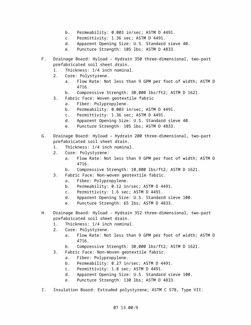
3. Fabric Face: Woven geotextile fabric.a. Fiber: Polypropylene.b. Permeability: 0.003 in/sec; ASTM D 4491.c. Permittivity: 1.36 sec; ASTM D 4491.d. Apparent Opening Size: U.S. Standard sieve 40.e. Puncture Strength: 105 lbs; ASTM D 4833.
F. Drainage Board: Hyload - Hydrain 350 three-dimensional, two-part prefabricated soil sheet drain.1. Thickness: 1/4 inch nominal.2. Core: Polystyrene.
a. Flow Rate: Not less than 9 GPM per foot of width; ASTM D 4716.b. Compressive Strength: 30,000 lbs/ft2; ASTM D 1621.
3. Fabric Face: Woven geotextile fabrica. Fiber: Polypropylene.b. Permeability: 0.003 in/sec; ASTM D 4491.c. Permittivity: 1.36 sec; ASTM D 4491.
07 13 00-6

d. Apparent Opening Size: U.S. Standard sieve 40.e. Puncture Strength: 105 lbs; ASTM D 4833.
G. Drainage Board: Hyload - Hydrain 200 three-dimensional, two-part prefabricated soil sheet drain.1. Thickness: 1/4 inch nominal.2. Core: Polystyrene:
a. Flow Rate: Not less than 9 GPM per foot of width; ASTM D 4716.b. Compressive Strength: 10,800 lbs/ft2; ASTM D 1621.
3. Fabric Face: Non-woven geotextile fabric.a. Fiber: Polypropylene.b. Permeability: 0.12 in/sec; ASTM D 4491.c. Permittivity: 1.6 sec; ASTM D 4491.d. Apparent Opening Size: U.S. Standard sieve 100.e. Puncture Strength: 65 lbs; ASTM D 4833.
H. Drainage Board: Hyload - Hydrain 352 three-dimensional, two-part prefabricated soil sheet drain.1. Thickness: 1/4 inch nominal.2. Core: Polystyrene.
a. Flow Rate: Not less than 9 GPM per foot of width; ASTM D 4716.b. Compressive Strength: 30,000 lbs/ft2; ASTM D 1621.
3. Fabric Face: Non-Woven geotextile fabric.a. Fiber: Polypropylene.b. Permeability: 0.27 in/sec; ASTM D 4491.c. Permittivity: 1.8 sec; ASTM D 4491.d. Apparent Opening Size: U.S. Standard sieve 100.e. Puncture Strength: 130 lbs; ASTM D 4833.
I. Insulation Board: Extruded polystyrene; ASTM C 578, Type VII:1. Thickness: As indicated on Drawings.2. Thermal Resistance:
a. 1-1/2 inch - R 7.5b. 2 inch - R 10c. 2-1/2 inch - R 12.5d. 3 inch - R 15e. 3-1/2 inch - R 17.5f. 4 inch - R 20
3. Properties:a. Compressive Strength; ASTM D 1621: 60 psi minimum.b. Water Absorption; ASTM C 272: 0.1 percent by volume maximum.c. Water Vapor Permeance; ASTM E 96: 1.0 perm for 1 inch maximum.
2.4 TWO PLY SYSTEM
A. Base Ply Membrane: Self adhered, Hyload Hyproof SA fully adhered Elvaloy modified coal tar elastomeric sheet. Bottom of sheet coated with 15 mils of SBS-modified asphalt with a dry selvedge edge for hot air welds1. Thickness:
a. 60 mils membrane/15 mils adhesive/75 mils total.b. 75 mils membrane/15 mils adhesive/90 mils total.
2. Properties:a. Tensile Strength: ASTM D 638; 1000 psi minimumb. Elongation at Break: ASTM D 638; 150 percent minimumc. Seam Strength (minimum percent of tensile strength): ASTM D 638; 95
percent.d. Retention of Properties after Heat Aging: ASTM D 3045
07 13 00-7

e. Tensile Strength (minimum percent of original): ASTM D 638; 95 percent.f. Elongation (minimum percent of original): ASTM D 638; 90 percent.g. Tear Resistance: ASTM D 1004; 250 lb/in minimum.h. Low Temperature bend (-40 degreesF): ASTM D 2136; Pass.i. Linear Dimensional Change: ASTM D 1204; 9.0 percent maximum.j. Weight Change after Immersion in Water: ASTM D 570; 2.8 percent maximum.k. Water Vapor Permeance: ASTM E 96; 0.375 perms maximum.l. Puncture Resistance: Federal Method 2065; 44.0 pounds, minimum.
B. Base Ply Membrane: Uncoated Hyload GL Elvaloy modified coal tar elastomeric sheet.1. Thickness:
a. 60 mils membrane.b. 75 mils membrane.
2. Properties:a. Tensile Strength: ASTM D 638; 1000 psi minimum.b. Elongation at Break: ASTM D 638; 150 percent minimum.c. Seam Strength (minimum percent of tensile strength): ASTM D 638; 95
percent.d. Retention of Properties after Heat Aging: ASTM D 3045e. Elongation (minimum percent of original): ASTM D 638; 90 percent.f. Tear Resistance: ASTM D 1004; 250 lb/in minimum.g. Low Temperature bend (-40 degreesF): ASTM D 2136; Pass.h. Linear Dimensional Change: ASTM D 1204; 9.0 percent maximum.i. Weight Change after Immersion in Water: ASTM D 570; 2.8 percent maximum.j. Water Vapor Permeance: ASTM E 96; 0.375 perms maximum.k. Puncture Resistance: Federal Method 2065; 44.0 pounds, minimum.
C. Top Ply Membrane: Self adhered, Hyload Hyproof SA self adhered Elvaloy modified coal tar elastomeric sheet. Bottom of sheet coated with 15 mils of SBS-modified asphalt with a dry selvedge edge for hot air welds1. Thickness:
a. 60 mils membrane/15 mils adhesive/75 mils total.b. 75 mils membrane/15 mils adhesive/90 mils total.
2. Properties:a. Tensile Strength: ASTM D 638; 1000 psi minimumb. Elongation at Break: ASTM D 638; 150 percent minimumc. Seam Strength (minimum percent of tensile strength): ASTM D 638; 95
percent.d. Retention of Properties after Heat Aging: ASTM D 3045e. Tensile Strength (minimum percent of original): ASTM D 638; 95 percent.f. Elongation (minimum percent of original): ASTM D 638; 90 percent.g. Tear Resistance: ASTM D 1004; 250 lb/in minimum.h. Low Temperature bend (-40 degreesF): ASTM D 2136; Pass.i. Linear Dimensional Change: ASTM D 1204; 9.0 percent maximum.j. Weight Change after Immersion in Water: ASTM D 570; 2.8 percent maximum.k. Water Vapor Permeance: ASTM E 96; 0.375 perms maximum.l. Puncture Resistance: Federal Method 2065; 44.0 pounds, minimum.
D. Membrane Flashing: Hyload SA modified coal tar elastomeric sheet1. Thickness: Not less than 60 mils.2. Sheet Width: 9 inches, and/or 12 inches as needed.
E. Sealing Strips: Hyproof GL sealing strip.1. Thickness: Not less than 60 mils.2. Sheet Width: 4 inches, 6 inches as needed.
F. Preformed Three Dimensional Shapes: Hyload - Cloaks
07 13 00-8
1. Shapes: As needed to meet Project requirements including, but not limited to detail corners, level changes, stop ends, and other similar special applications.
G. Drainage Board: Hyload - Hydrain 650 three-dimensional, two-part prefabricated soil sheet drain:1. Thickness: 7/16 inch nominal.2. Core: Polystyrene.
a. Flow Rate: Not less than 18 GPM per foot of width; ASTM D 4716.b. Compressive Strength: 21,000 lbs/ft2; ASTM D 1621.
3. Fabric Face: Woven geotextile fabric.a. Fiber: Polypropylene.b. Permeability: 0.003 in/sec; ASTM D 4491.c. Permittivity: 1.36 sec; ASTM D 4491.d. Apparent Opening Size: U.S. Standard sieve 40.e. Puncture Strength: 105 lbs; ASTM D 4833.
H. Drainage Board: Hyload - Hydrain 350 three-dimensional, two-part prefabricated soil sheet drain.1. Thickness: 1/4 inch nominal.2. Core: Polystyrene.
a. Flow Rate: Not less than 9 GPM per foot of width; ASTM D 4716.b. Compressive Strength: 30,000 lbs/ft2; ASTM D 1621.
3. Fabric Face: Woven geotextile fabrica. Fiber: Polypropylene.b. Permeability: 0.003 in/sec; ASTM D 4491.c. Permittivity: 1.36 sec; ASTM D 4491.d. Apparent Opening Size: U.S. Standard sieve 40.e. Puncture Strength: 105 lbs; ASTM D 4833.
I. Drainage Board: Hyload - Hydrain 200 three-dimensional, two-part prefabricated soil sheet drain.1. Thickness: 1/4 inch nominal.2. Core: Polystyrene:
a. Flow Rate: Not less than 9 GPM per foot of width; ASTM D 4716.b. Compressive Strength: 10,800 lbs/ft2; ASTM D 1621.
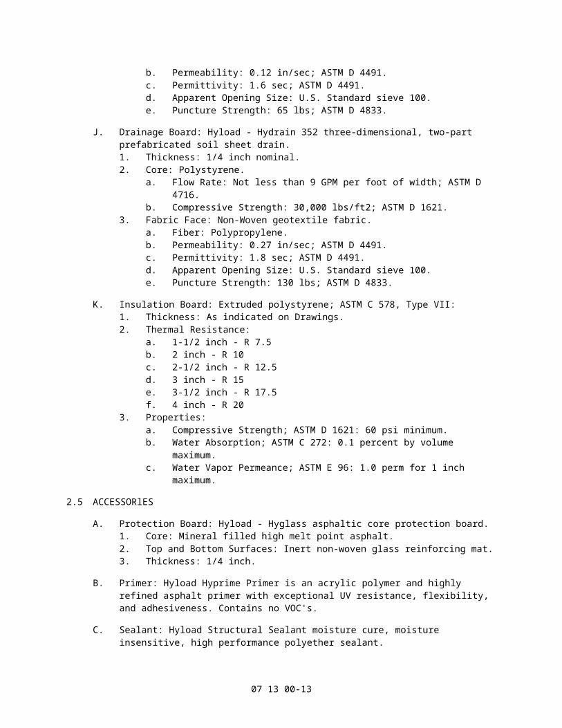
3. Fabric Face: Non-woven geotextile fabric.a. Fiber: Polypropylene.b. Permeability: 0.12 in/sec; ASTM D 4491.c. Permittivity: 1.6 sec; ASTM D 4491.d. Apparent Opening Size: U.S. Standard sieve 100.e. Puncture Strength: 65 lbs; ASTM D 4833.
J. Drainage Board: Hyload - Hydrain 352 three-dimensional, two-part prefabricated soil sheet drain.1. Thickness: 1/4 inch nominal.2. Core: Polystyrene.
a. Flow Rate: Not less than 9 GPM per foot of width; ASTM D 4716.b. Compressive Strength: 30,000 lbs/ft2; ASTM D 1621.
3. Fabric Face: Non-Woven geotextile fabric.a. Fiber: Polypropylene.b. Permeability: 0.27 in/sec; ASTM D 4491.c. Permittivity: 1.8 sec; ASTM D 4491.d. Apparent Opening Size: U.S. Standard sieve 100.e. Puncture Strength: 130 lbs; ASTM D 4833.
K. Insulation Board: Extruded polystyrene; ASTM C 578, Type VII:1. Thickness: As indicated on Drawings.
07 13 00-9

2. Thermal Resistance:a. 1-1/2 inch - R 7.5b. 2 inch - R 10c. 2-1/2 inch - R 12.5d. 3 inch - R 15e. 3-1/2 inch - R 17.5f. 4 inch - R 20
3. Properties:a. Compressive Strength; ASTM D 1621: 60 psi minimum.b. Water Absorption; ASTM C 272: 0.1 percent by volume maximum.c. Water Vapor Permeance; ASTM E 96: 1.0 perm for 1 inch maximum.
2.5 ACCESSORlES
A. Protection Board: Hyload - Hyglass asphaltic core protection board.1. Core: Mineral filled high melt point asphalt.2. Top and Bottom Surfaces: Inert non-woven glass reinforcing mat.3. Thickness: 1/4 inch.
B. Primer: Hyload Hyprime Primer is an acrylic polymer and highly refined asphalt primer with exceptional UV resistance, flexibility, and adhesiveness. Contains no VOC's.
C. Sealant: Hyload Structural Sealant moisture cure, moisture insensitive, high performance polyether sealant.
D. Membrane Adhesive: Hyload Membrane Adhesive moisture cure, moisture insensitive, high performance polyether adhesive.
E. Adhesive Mastic: Hyload Trowel-On Membrane (TOM) waterproofing mastic that can be applied in beads from a 28 oz caulking tube or trowel-applied from 2 or 5 gallon pails.
F. Metal Termination Bars: Extruded aluminum pre-punched at 6 inches on center; 1 inch wide by 1/8 inch thick.
G. Concrete Preparation Materials:1. Bonding Bridge. Bonding Agent: Sika - Sikadur 32, Hi-Mod.2. Polymer Modified Patching Mortar:
a. Horizontal Application Product: Sika - SikaTop 122.b. Vertical and Over Head Application Product: Sika - SikaTop 123.
3. Crack Filler: Sika - SikaTop 111.
PART 3 EXECUTION
3.1 EXAMINATION
A. Do not begin installation until substrates have been properly prepared.1. Concrete substrate shall be cured not less than 7 days and be clean, dry, and frost
free before application of waterproofing system.2. Concrete block or brick substrates shall have smooth trowel-cut mortar joints or shall
be treated with a parge coat.3. Substrates shall be inspected and repaired as needed to provide a proper surface to
receive waterproofing system.4. Verify items penetrating surfaces to receive waterproofing are securely installed.5. Verify substrate surface slopes to drain for horizontal waterproofing applications.6. Identify incompatible substrates, if any.
B. If substrate preparation is the responsibility of another installer, notify Architect of
07 13 00-10

unsatisfactory preparation before proceeding.
3.2 PREPARATION
A. Protect adjacent surfaces not designated to receive waterproofing.
B. Clean surfaces thoroughly prior to installation.
C. Exercise care that structure is not overloaded during application.
D. Install temporary waterstops at end of each day's work and remove before proceeding with next day's work. Waterstops shall be compatible with materials and shall not emit dangerous or incompatible fumes.
E. Liquid materials such as solvents and adhesives shall be stored and used away from open flames, sparks and excessive heat.
F. Verify that drain lines are un-blocked before starting work.
G. Take necessary precautions when using volatile materials around air in-takes. Coordinate equipment to be turned off and on with Owner if necessary.
H. Prepare surfaces using the methods recommended by the manufacturer for achieving the best result for the substrate under the project conditions.
I. Surface Preparation:1. Provide a smooth, clean substrate suitable for adhesion of waterproofing system.
Remove substances that could inhibit bonding of membrane and waterproofing system. Substantially clean substrate to provide a smooth, even surface to greatest extent practical.
2. Remove concrete form release coatings and curing compounds. Contaminants such as dirt, debris, loose materials, moisture, or surface irregularities shall be removed.
3. Grind down projections greater than 1/8". Grind, round off, and smooth sharp corners and edges. Patch and fill voids and holes greater than 1/2 inch with patching mortar.
4. New concrete shall be dry to the touch before application of membrane sheets.5. If covering over a previously existing waterproofing system, substantially remove such
that a solid, undisturbed substrate is achieved. Contact Hyload for specific applications.
J. Surface Priming (only):1. Apply Hyload Hyprime Primer at minimum rate of 1 gallon per 100 square feet. Allow
primer to dry completely.2. Application of primer shall be limited to what can be covered with membrane in a
given workday. Primed areas not covered by membrane during workday shall be re-primed.
3. Re-prime areas contaminated with dirt or dust.4. Mask adjacent areas to control application of primer. Remove spilled and misapplied
primer.
K. Concrete Joint and Crack Treatment:1. Cracks in concrete less than 1/16 inch wide shall be pre-treated with a 1/16 inch (60
mil) coating of mastic adhesive 2 inches wide centered on crack.2. Apply 6 inches Hyproof GL sealing strip membrane centered over cracks wider than
1/16 inch set in 2 continuous 1/4 inch beads of Hyload Structural Sealant, one on each side of crack.
L. Detailing:1. Apply 6 inch flashing membrane centered over vertical corners and horizontal to
07 13 00-11

vertical transitions set in 2 continuous 1/4 inch beads of Hyload Structural Sealant, one on each side of corner.
2. Make flashing membrane strips continuous. Overlap end joints by a minimum of 3 inches and either hot air weld or set in continuous 1/4 inch bead of Hyload Structural Sealant inside lap.
3. Seal joints in substrates.4. Provide a minimum of 3/4 inch Hyload Structural Sealant fillet at inside corners.5. Provide flashings at changes of plane and around penetrations.6. Apply a liberal bead of Hyload Structural Sealant at obstructions to continuous sheet
waterproofing.
3.3 SHEET MEMBRANE APPLICATION
A. General Requirements:1. Proceed with waterproofing application only after substrate preparation is complete.
Obtain acceptance of concrete surface from membrane manufacturer's field representative before proceeding with membrane application.
2. Apply and detail waterproofing system in compliance with manufacturer's instructions, recommendations, standard details, and project specific details. Use only proprietary membrane components and materials, as supplied by membrane manufacturer. Form terminations to match manufacturer's standard details including sealed termination bars.
3. Continuously seal terminations including temporary terminations with Hyload Structural Sealant.
4. Flash sheet waterproofing system into drains, if any. Make installation 100 percent waterproof.
5. Ensure waterproofing system is concealed from view in completed work.6. Coordinate installation of counter flashings and covering construction.7. Apply only as much waterproofing membrane as can be made weathertight each day
including flashing work. Do not permit water to penetrate under sheet waterproofing.
B. SA Membrane:1. Exercise care to not trap air pockets under membrane during application.2. Roll entire membrane firmly and completely as soon as possible. For horizontal
applications, roller shall be a minimum of 30 inches wide and 70 pounds. Roller shall be cushioned with a resilient material such as foam or carpet. For vertical applications, a hand-held roller with rubber or neoprene wheels shall be firmly used.
C. GL Membrane:1. Apply 1/2 inch beads of Hyload Membrane Adhesive in a 12 inch intersecting grid
pattern.2. Lay Hyload sheets over adhesive grid and broom membrane into place over entire
area. Exercise care to not flatten beads out paper-thin, maintain a 1/16 inch to 1/8 inch bead profile.
D. Grid Lock Base-Ply Membrane:1. Apply 1/2 inch beads of Hyload Membrane Adhesive in a 12 inch intersecting grid
pattern.2. Lay Hyload membrane sheets over adhesive grid and broom membrane into place
over entire area. Exercise care to not flatten beads out paper-thin, maintain a 1/16 inch to 1/8 inch bead profile.
E. Self-Adhered Top-Ply Membrane:1. Apply Hyload sheets beginning at low point of roof or center of drain to base sheet
following manufacturer's printed instructions.2. Exercise care to not trap air pockets under membrane during application.3. Roll entire membrane firmly and completely as soon as possible. For horizontal
07 13 00-12
applications, roller shall be a minimum of 30 inches wide and 70 pounds. Roller shall be cushioned with a resilient material such as foam or carpet. For vertical applications, a hand-held roller with rubber or neoprene wheels shall be firmly used.
F. For Horizontal or Low-Slope Applications:1. For horizontal, or low-slope applications, apply Hyload sheets from low point to high
point so that laps shed water. Perimeters and penetrations shall be picture framed with sheets that run parallel to perimeter or penetration opening.
2. To greatest extent possible, form minimum 8 inch high curbs at horizontal applications.
G. For Vertical Applications:1. For vertical applications, apply Hyload sheets in lengths up to 8 feet. On higher walls
install sheets in two or more lifts. Hyload sheets may also be installed horizontally in shingle fashion.
2. Terminate membrane a minimum of 12 inches above grade level secured by a termination bar fastened every 6 inches. Cover termination with a membrane counter-flashing.
3. Where a vertical membrane meets a horizontal substrate extend vertical membrane onto horizontal by a minimum of 6 inches.
4. Terminate a vertical membrane at base of a wall only if bottom elevation of an interior floor slab is a minimum of 12 inches above footing. Terminate Hyload sheets on top of footing if vertical waterproofing ties into mud slab waterproofing or if bottom elevation of interior floor slab is less than 12 inches above footing. Extend membrane a minimum of 12 inches onto mud slab waterproofing and dress terminating edge with a bead of Hyload Structural Sealant.
5. Seal or terminate upper lift by end of each day.
H. Lapping and Joining Sheets:1. Follow lap guidelines printed on sheet waterproofing.2. Adjacent sheets of membrane shall be securely and completely joined together by
either hot air welding or by application of Hyload Structural Sealant.3. Side laps shall be a minimum of 3 inches end laps a minimum of 9 inches. Stagger
end laps by a minimum of 12 inches. Exercise care to avoid stretching sheets as they are applied. If stretched, sheets will recover overnight to their original dimensions.
4. Hot air weld side laps. Dress end laps with a 1/2 inch bead of Hyload Structural Sealant. Dress T-joints with 1/2 inch beads of Hyload Structural Sealant. In situations where hot air welding of side laps is restricted or otherwise impractical, a finished lap shall be achieved by placing a continuous 1/2 inch bead of Hyload Structural Sealant positioned 3/4 inch from edge under overlying membrane. Set lap by applying sufficient pressure over bead such that it just starts to bleed out from under overlying membrane.
5. Make minimum 4 inches laps at patches, repairs, and penetrations.
I. Membrane Flashing:1. For Horizontal or Low-Slope Applications:
a. Flashing membrane shall lap over onto field membrane by a minimum of 6 inches.
b. Flashing membrane shall extend vertically a minimum of 9 inches above finished wear surface or grade. Secure top of flashing sheet with a termination bar fastened every 6 inches.
c. Junction of flashing to substrate, termination bar, and fasteners shall be covered and sealed with Hyload Waterproofing Mastic applied a minimum of 1/8 inch thick.
d. Cover termination with a membrane counter-flashing.2. For Vertical Applications:
07 13 00-13

a. Terminate membrane a minimum of 12 inches above grade level secured by a termination bar fastened every 6 inches. Junction of flashing to substrate, termination bar, and fasteners shall be covered and sealed with Hyload Waterproofing Mastic applied a minimum of 1/8 inch thick. Cover termination with a counter-flashing.
b. Where a vertical membrane meets a horizontal substrate, extend vertical membrane onto horizontal by a minimum of 6 inches. Terminate a vertical membrane at base of a wall only if bottom elevation of an interior floor slab is a minimum of 12 inches above footing. Seal termination with Hyload Waterproofing Mastic applied a minimum of 1/8 inch thick.
c. Terminate membrane on top of footing if vertical waterproofing ties into mud slab waterproofing or if bottom elevation of interior floor slab is less than 12 inches above footing. Extend membrane a minimum of 12 inches onto mud slab waterproofing and seal termination with Hyload Waterproofing Mastic applied a minimum of 1/8 inch thick.
J. Corners and Intersections:1. At intersections of one horizontal and one vertical plane forming a 2-way inside
corner, or two vertical planes forming a 2-way inside corner, treat inside corner by creating a minimum 3/4 inch fillet, or cant, using Hyload Waterproofing Mastic. Extend mastic onto both horizontal and vertical planes a minimum of 6 inches by 1/8 inch thick. Apply membrane snugly into corner over mastic.
2. At intersections of one horizontal and one vertical plane, or two vertical planes, forming an outside corner, grind off sharp edges such that a minimum 1/8 inch beveled corner is created. Apply a full sheet of membrane snugly over treated corner during installation.
3. At intersections of one horizontal and two vertical planes forming a 3-way inside or outside corner, set appropriate pre-formed Hyload Cloak into a 1/8 inch continuous bed of Hyload Waterproofing Mastic that extends a minimum of 6 inches in all directions out from corner. Extend vertical and horizontal field sheet of membrane onto cloak by a minimum of 3 inches in each direction.
4. Field membranes shall be secured to Hyload Cloak by either hot air welding or by setting field membranes into a 1/8 inch bed of Hyload Structural Sealant that has been applied to cloak. Whether hot air welding to cloak or setting membranes in sealant onto cloak, edges of membrane on cloak shall be dressed with a 1/2 inch bead of Hyload Structural Sealant.
K. Penetrations:1. Apply Hyload sheets to within 1 inch of base of penetration. Dress edge of Hyload
sheet with a 1/2 inch bead of Hyload Structural Sealant.2. Apply a minimum 1/8 inch of Hyload TOM around penetration a minimum of 6 inches
onto Hyload membrane and up penetration to just below height of completed overlay.
L. Protection Board:1. Waterproofing membrane is not designed for permanent exposure. Protect membrane
from abuse as soon as possible following membrane application.2. Apply protection board promptly following application of membran. Boards shall be
adhered to membrane using adhesive mastic.3. Adhesive shall be applied in compliance with manufacturer's instructions.4. Boards shall be butted together with no gaps larger than 1/4 inch.
3.4 DRAINAGE BOARDS
A. Vertical Application:1. Apply drainage board promptly following application of membrane waterproofing and
protection board in compliance with manufacturer's recommendations.2. Starting at base of wall place base-drain horizontally oriented with open core side up
07 13 00-14

and 2 inches flap of fabric side against wall. Install base-drain over protection board applied over waterproofing membrane, using methods approved by waterproofing material manufacturer.a. Typical attachment methods include general construction adhesive or two-sided
tape.b. Fabric flap along top edge should be secured.c. Use couplers and corner fittings as needed to form a continuous installation.d. Install discharge outlet fittings to connect with discharge pipes.
3. Install drainage board with plastic core side toward wall where bottom core edge overlaps 2 inch fabric flap of base-drain and abuts base-drain plastic core. Apply drainage board over protection board applied over waterproofing membrane using a method approved by waterproofing material manufacturer.a. Typical attachment methods include construction adhesive or two-sided tape.b. Place extra fabric flap of drainage board over front of base-drain to cover open
top edge and then secure extra fabric flap with general construction adhesive or duct tape.
4. Install subsequent drainage boards to finished grade or as indicated on Drawings.a. Connect adjacent panels at end by pulling filter fabric back to expose two rows
of core dimples and interlocking core dimples with installed panel. With next course, flangeless panel edge shall be placed over top flange edge of panel below and butted dimple to dimple.
b. Connections shall be completed in shingle fashion so that water will flow with overlap and not against it.
c. Overlap extra fabric in direction of water flow and secure with construction adhesive or duct tape. Wrap panel termination edges with filter fabric flap by tucking fabric behind core.
5. For inside and outside corners abut adjoining drainage composite at corner. Cover open core with extra filter fabric to prevent intrusion of soil into core.
6. Around protrusions, cut drainage composite to fit and wrap extra filter fabric around open edge of core to prevent soil intrusion into core.
7. Secure drainage boards to wall at grade with termination bar mechanically fastened 12 inches on center with fabric wrapped behind exposed core to prevent intrusion of soil into the core.
8. Tears or punctures in fabric shall be covered with new filter fabric.
B. Horizontal Application:1. Filter fabric shall face direction from which water will come.2. It is not necessary to anchor drainage panels in most applications; follow panel
manufacturer's recommendations.3. Tuck filter fabric behind core to cover exposed edges. Tears or punctures in fabric
shall be covered with new filter fabric.4. For drainage below cast-in-place concrete wearing surfaces, do not place concrete
directly on filter fabric. Place a sacrificial layer of 3 to 4 ounce, non-woven filter fabric over filter fabric integral with drainage panels to prevent primary filter fabric from clogging.
5. Rebar chairs shall be placed on metal or plastic plates to distribute load to prevent primary filter fabric from clogging.
3.5 INSULATION BOARDS
A. Place insulation boards, un-adhered, over membrane with drain channels down. End joints shall be staggered.
B. Boards shall be tightly butted together with no gaps greater 3/8 inch.
C. Insulation shall be neatly fitted to within 3/4 inch of roof penetrations, projections, cant strips, etc.
07 13 00-15

D. When multi-layer insulation applications are involved bottom layer of insulation shall be thickest layer and shall be not less than 2 inches thick. Layers shall be installed unadhered to each other and joints in relation to underlying layers staggered.
E. No more insulation shall be installed than can be covered and completed before end of day's work, or before onset of inclement weather
3.6 FIELD QUALITY CONTROL
A. Coordinate with Testing and Inspection services provided in accordance with Section 01 40 00 - Quality Requirements.
B. The Owner will employ and pay for services of an independent inspection agency to monitor waterproofing material installation for compliance with Contract Documents and manufacturer's published literature, perform professional consultation, inspections, tests, and other services specified.
C. Inspections:1. Inspection service shall perform continuous inspection of installation.2. Include substrate examination, beginning of waterproofing installation, interim
inspection, and final inspection prior to backfilling or pouring of concrete against waterproofing.
3. Report inspection results in writing to Contractor, waterproofing installer, waterproofing material manufacturer, Owner, and Architect on same day that inspections are made. Reports indicating non-compliance shall be faxed immediately to parties on distribution list, Architect, Owner, and Contractor. Each report shall include:a. Date issuedb. Project title and numberc. Testing agency name, address, and telephone numberd. Name and signature of certifying agency personnele. Date and time of inspectionf. Record of temperature and weather conditionsg. Identification of product and Specification Section paragraph referenceh. Location of inspection in Projecti. Indication of satisfactory compliance with Contract Documentsj. Report unsatisfactory conditions or failure to comply with requirements of
Contract Documents and shop drawings.4. Testing and inspection agency personnel are not authorized to:
a. Revoke, alter, enlarge on, or release requirements of Contract Documentsb. Approve or accept any portion of Workc. Perform duties of Contractor
5. Materials and workmanship not meeting specified standard of performance shall be removed and replaced at Contractor's expense, including subsequent repeating of tests and inspections.
D. Flood Testing: ASTM D 5957.1. Prior to flood testing, ascertain from structural engineer that structure will withstand
dead load of water used for testing.2. Flood testing of horizontal waterproofing shall be done prior to placement of protection
board. Not less than 2 inches of water shall be placed over finished membrane for at least 24 hours.
3. Mark leaks and make repairs when membrane is dry. Membrane shall be re-tested following corrections.
4. Prepare a written report of flood testing, and submit to Architect within 7 days following test. Report results of tests, both successful and unsuccessful. Report shall include date of test, project name, list of products being applied and tested, name of
07 13 00-16

applicator, name of Contractor, and conditions causing failure of waterproofing in event of an unsuccessful test. Alternatively, employ EFM (Electric Field Mapping) leak detection method.
E. Electric Field Mapping:1. Leak detection of horizontal waterproofing shall be done utilizing electrical conduction
method (EFM).2. Provide testing to verify membrane is free of holes, open seams and capillary defects
that will allow water to pass.3. For areas to receive EFM testing provide following:
a. Thoroughly wet waterproofing membrane in area of test. Wetting can be accomplished by hand or mechanical spray devises. Membrane shall be wet during testing procedures. Ponded water shall not be necessary.
b. Place conductor wire on wetted, bare membrane. Secure wire with small strips of waterproofing or other compatible membrane or tape. Overburden, insulation, drainage composites and filter fabric shall not be installed prior to initial test.
c. Allow testing technician to locate membrane breaches, if any. Technician shall mark on waterproofing membrane or surface exact location of defect and assign an identification number to each location.
d. Visually inspect entire membrane area and repair breaches found. An EFM retest shall be performed to confirm integrity of repair(s).
4. Technician shall prepare a report of each day's test results containing a written description and photograph of defect(s) located and a schematic CAD drawing indicating location of conductor wire and of defect(s) located in testing field to within 1 inch of accuracy. This report shall be made available in hard copy.
5. Submit written report of EFM tests to Architect within 7 days following testing. Report results of tests, both successful and unsuccessful. In addition to results, report shall include date of test, project name, list of products being applied and tested, name of applicator, name of Contractor, and conditions causing failure of waterproofing in event of an unsuccessful test.
3.7 CLEANING
A. Waterproofing materials, components and accessories shall be removed from Site and taken to a legal dumping area authorized to receive such materials.
3.8 PROTECTION
A. Protect installed products until completion of project.
B. Protect horizontal and vertical membranes after installation and testing with a protection course or drainage mat. Install protection course or drainage mat within 24 hours after completion of testing.1. Eliminate construction traffic on newly tested membrane systems. Do not store
construction materials on unprotected membrane surfaces.2. Trafficking or storing materials on tested membrane can introduce additional damage
to waterproofing system and will nullify testing procedures.3. Membrane areas that are observed to be trafficked or used as a storage/working
platform shall be retested and immediately repaired and covered with insulation and drainage composite.
3.9 REPAIR
A. Inspect membrane before covering and make repairs immediately. Patch tears, punctures, seams, or other deficiencies with a membrane patch that extends a minimum of 6 inches in every direction beyond defect. Dress edges of patch with not less than 1/2 inch bead of
07 13 00-17
Hyload Structural Sealant.
END OF SECTION
07 13 00-18