· web viewthe coefficient of discharge cd for triangular weirs note that h should be measured at...
TRANSCRIPT

Weir Experiment Triangular
Name: Mohamed kamel Mohamed Mohamed
Sec: 11
B.n:25

Objectives of the Experiment:
1. To demonstrate the flow over different weir types.
2. To calculate the coefficient of discharge for different weir types.
3. To study the variation and dependence of the relevant parameters.
Theory:
Q = Cd. Tan (θ/2). (√2g). (8/15). (H^2.5)
Where:
Cd = Coefficient of discharge
H = head above the weir crest or apex
θ = angle of the triangular weir
g = acceleration of gravity
Note:
Qcalculated = Cd (8/15) (2g) 1/2 tan (θ/2) H5/2
The coefficient of discharge Cd for triangular weirs
Note that H should be measured at a distance sufficiently far upstream of the weir to
Avoid the “draw down” region shown in Figure 1.
Plot Qmeasured and Qcalculated against H as it is varied over a range of values, for
The two
Weirs. The accuracy of Qcalculated can then be judged from these plots.

Figure-1
Experiment Description:
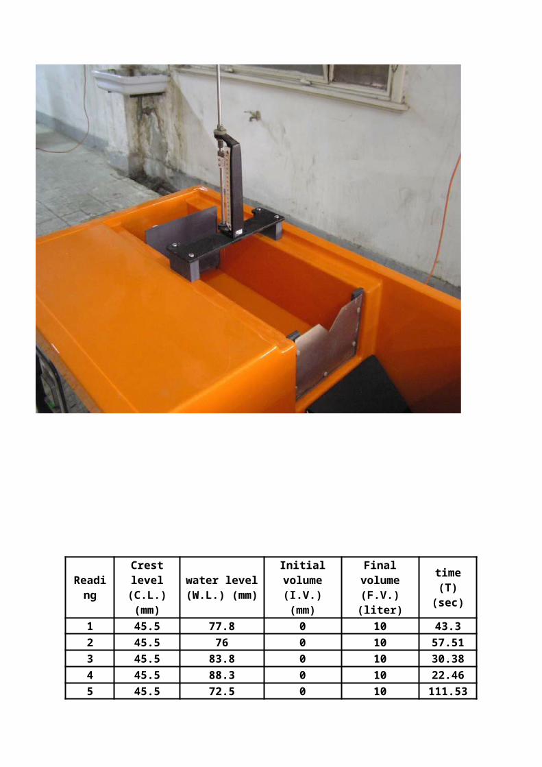
1. The rectangular or triangular weir plate is attached to the regular Hydraulic Bench
As shown in the photographs. 2. A stopwatch, a hook or a point gauge are also needed with the experiment.
Hydraulic Bench:
The standard Hydraulics Bench is used for all the laboratory experiments carried out
During this course. The Bench has a closed water circulating system to facilitate
Mobility. Water is stored in an enclosed tank at the bottom of the bench then
pumped up to the experimental setup situated on top of the bench from which
Water flows into the upper tank. The upper tank has a drain controlled by a plug to
Collect and gauge the water in the upper tank after which water is drained to the.

Bottom tank. The volume of water collected in the upper tank (in liters) can be
Measured using the graduated scale fixed at the side of the Hydraulics Bench. The
Switch of the water pump and the control valve that regulates the amount of water
That flows to the experimental setup are at the front side of the Hydraulics Bench
( Please see the attached photographs.)
Reading
Crest level (C.L.) (mm)
water level (W.L.) (mm)
Initial volume (I.V.) (mm)
Final volume (F.V.) (liter)
time (T) (sec)
1 45.5 77.8 0 10 43.32 45.5 76 0 10 57.513 45.5 83.8 0 10 30.384 45.5 88.3 0 10 22.465 45.5 72.5 0 10 111.53
Reading
Volume = F.V.-I.V.
(liter)
H = W.L.-C.L. (cm)
Q = Volume / time (cm3 / s) Log Q Log H H^2.5 Time
(sec) Cd
1 10 32.3 230.9468822 2.36351 1.50920 5929.33 43.3 0.0164
2 10 30.5 173.882803 2.24025 1.48429 5137.47 57.51 0.0143
3 10 38.3 329.1639236 2.51741 1.58319 9078.14 30.38 0.0153
4 10 42.8 445.2359751 2.64859 1.63144 11984.21 22.46 0.0157
5 10 27 89.66197436 1.95260 1.43136 3787.99 111.53 0.01001

62 82 03 23 43 63 83 04 24 440
05
001
051
002
052
003
053
004
054
005
17740937.12=epols
H
Q
0003 0004 0005 0006 0007 0008 0009 00001 00011 00021 000310
05
001
051
002
052
003
053
004
054
005
26632140.0=epols
5.2^H
Q

4.1 54.1 5.1 55.1 6.1 56.10
5.0
1
5.1
2
5.2
3
330772.3=epols
H gol
Q gol
62 82 03 23 43 63 83 04 24 440
200.0
400.0
600.0
800.0
10.0
210.0
410.0
610.0
810.0
367962000.0=epols
H
dC