· web viewyour rossignol bindings should be mounted, adjusted and inspected by a certified...
TRANSCRIPT

Mounting and Adjusting Rossignol Axium 100 and Axium 110/200 Scratch Bindings on the Spruce Mountain Pro
Series Riser
A word of caution from Rossignol: “Your boot binding system does not guarantee you will release at all times nor under all circumstances and it is not possible to predict every situation in which it will release and therefore does not constitute a guarantee of absolute safety." In other words, modern release bindings are very good devices, but they are not perfect.
Your Rossignol bindings should be mounted, adjusted and inspected by a certified technician at a certified Rossignol binding dealer in accordance with the specifications and guidelines in the most current Rossignol alpine binding technical manual. Should you choose to mount and/or adjust your bindings yourself, the instructions below will assist you in doing this.
To mount and adjust your bindings you will need a #3 Phillips screwdriver and a medium to large flat bladed screwdriver along with your skiboots.
The pictures used in these instructions for illustration are of a Rossignol Axium 100 binding. The Rossignol Axium 110/200 binding is mounted and adjusted in exactly the same way as the Axium 100.
A. Mounting the Bindings
Step 1 - Removing the Bindings From Their Shipping Position.
1.) Remove the tape holding the risers or the skiboards together.
2.) Using the #3 Phillips screwdriver, remove the four screws holding the binding toe pieces on the risers. (see Picture 1)
3.) Again using the #3 Phillips screwdriver, remove the four screws holding the heel pieces on the risers (see Picture 2)

Picture 1
Picture 2
Step 2 - Selecting the correct Mounting Holes1.) Determine the length of the sole of your boots in millimeters. This size is
molded into the side of the heel of each boot and looks like “315 mm” or "mm 315".
2.) Using the length of your boot sole, determine the correct binding mounting positions by looking in Table 1 or Table 2 below. Use Table 1 if you have Axium 100 bindings (standard with the Pro Lite model). Use Table 2 if you have Axium 110/200 Scratch bindings (standard with the Pro Prime model).
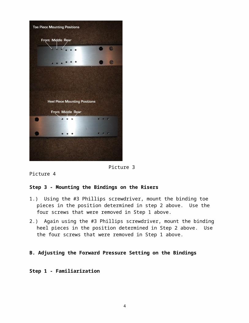
3.) Using the mounting positions for the toe and heel piece that were obtained from the appropriate table, locate the correct set of mounting holes by consulting Pictures 3 and 4.
Binding Positions for Axium 100 Binding (Pro Lite)
Boot Size (mm) Position of Toe Piece Position of Heel Piece331 - 350 Front Rear324 - 330 Front Middle313 - 323 Middle Rear297 - 312 Middle Middle284 - 296 Rear Middle270 - 283 Rear Front
Table 1
Binding Position for Axium 110/200 Scratch Binding (Pro Prime)
Boot Size (mm) Position of Toe Piece Position of Heel Piece2
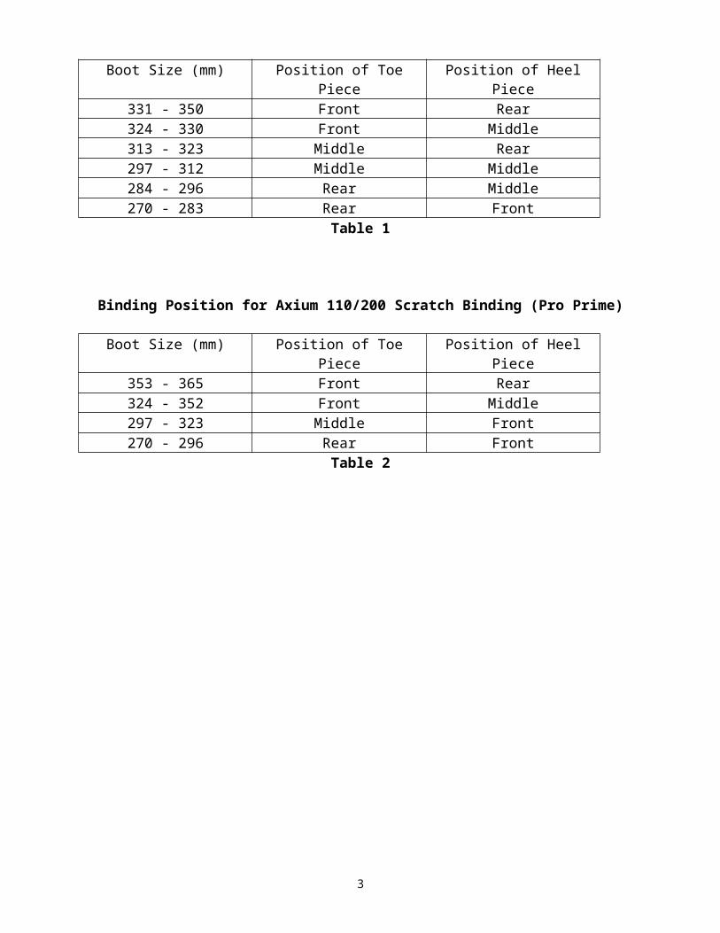
353 - 365 Front Rear324 - 352 Front Middle297 - 323 Middle Front270 - 296 Rear Front
Table 2
Picture 3 Picture 4
Step 3 - Mounting the Bindings on the Risers
1.) Using the #3 Phillips screwdriver, mount the binding toe pieces in the position determined in step 2 above. Use the four screws that were removed in Step 1 above.
2.) Again using the #3 Phillips screwdriver, mount the binding heel pieces in the position determined in Step 2 above. Use the four screws that were removed in Step 1 above.
B. Adjusting the Forward Pressure Setting on the Bindings
Step 1 - Familiarization
3
The forward pressure setting is the most critical adjustment on a modern release binding. If it is not set correctly, the binding will give false releases - usually when you least expect it. This setting is quick and easy to do on the Rossignol Axium series of bindings. First, familiarize yourself with the way the heel piece is adjusted by referring to Pictures 5 and 6 below and to your actual bindings.
Picture 5
1.) The heel piece has a small window on each side with an indicator groove in it. (When the boot is out of the binding, the groove is just barely visible at the rear of the window.) When the heel piece is adjusted correctly in its track and the boot is snapped into the binding, the indicator groove will be in the middle of the window or slightly forward of the middle.
2.) The adjustment of the position of the heel piece in it's track is done using a flat blade screwdriver. The screwdriver blade is inserted under the heel piece release lever (see Picture 6) and then the blade is lifted to release the heel piece in its track. The heel piece position can then be adjusted by sliding it in the track to the desired position.
4

Picture 6
Step 2 Fitting the Boot Into the Binding1. See if your boot fits into the binding so that the heel piece snaps down
when you insert the toe of the boot into the toe piece and push the heel of the boot downward.
2. If it does, you will not need to change the position of the heel piece to check the forward pressure setting. Go to Step 3 below.
3. If the boot is either too big or too small to snap into the binding, you must adjust the heel piece as described in Step 1 above. Adjust the heel piece in its track so that the boot is a tight fit into the binding and snap it into place.
Step 3 – Observing the Forward Pressure Setting1. With the boot snapped into the binding, note the position of the indicator
groove in the forward pressure indicator window (Picture 5). When the forward pressure is set correctly, the groove will be in the center or slightly forward of the center of the window.
2. If the indicator groove is at the rear of the indicator window, the binding is too loose and the heel piece must be moved forward in its track. If the indicator groove is at the forward end of the window, the binding is too tight and the heel piece must be moved to the rear in its track. When adjusting the heel piece position to get the correct indicator position, it is best to move the heel piece just one position at a time (3mm) in its track.
3. After each movement of the heel piece, recheck the indicator position. Continue this process until the indicator is in the correct position in the indicator window.
You are now ready to adjust the release settings on the toe and heel pieces.
5

C. Adjusting Your Bindings to the Correct DIN settingsThe adjustment of the DIN settings on your bindings requires that you know:
Weight and Height Age Boot Sole Length in Millimeters Skier Classification
Skier classification is determined as follows:Type I skiers:
Ski conservatively – prefer slower speeds Prefer easy, moderate slopes Type I settings apply to entry level skiers uncertain of their classification
Type II skiers: Ski moderately Prefer a variety of speeds Ski on varied terrain Are all skiers who do not meet the all the descriptions of either Type I or Type III
Type III skiers: Ski aggressively Normally ski at high speeds Prefer steeper and more challenging terrain
Locating the Correct DIN setting in Chart 1 Determine the skier code by locating the weight in the first column and
height in the second column of Chart 1. If these values are not on the same line, choose the skier code from the line closest to the top of the chart.
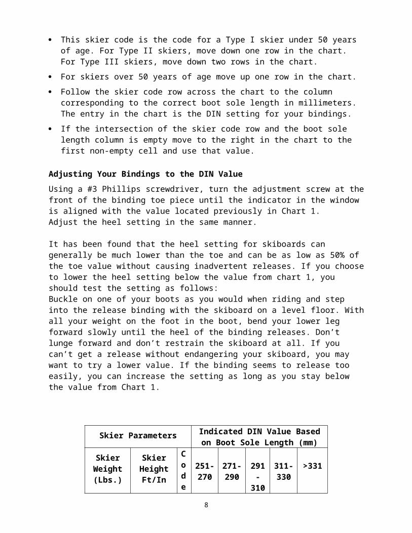
This skier code is the code for a Type I skier under 50 years of age. For Type II skiers, move down one row in the chart. For Type III skiers, move down two rows in the chart.
For skiers over 50 years of age move up one row in the chart. Follow the skier code row across the chart to the column corresponding to
the correct boot sole length in millimeters. The entry in the chart is the DIN setting for your bindings.
If the intersection of the skier code row and the boot sole length column is empty move to the right in the chart to the first non-empty cell and use that value.
6

Adjusting Your Bindings to the DIN ValueUsing a #3 Phillips screwdriver, turn the adjustment screw at the front of the binding toe piece until the indicator in the window is aligned with the value located previously in Chart 1. Adjust the heel setting in the same manner.
It has been found that the heel setting for skiboards can generally be much lower than the toe and can be as low as 50% of the toe value without causing inadvertent releases. If you choose to lower the heel setting below the value from chart 1, you should test the setting as follows: Buckle on one of your boots as you would when riding and step into the release binding with the skiboard on a level floor. With all your weight on the foot in the boot, bend your lower leg forward slowly until the heel of the binding releases. Don’t lunge forward and don’t restrain the skiboard at all. If you can’t get a release without endangering your skiboard, you may want to try a lower value. If the binding seems to release too easily, you can increase the setting as long as you stay below the value from Chart 1.
Skier Parameters Indicated DIN Value Based on Boot Sole Length (mm)
Skier Weight (Lbs.)
Skier Height Ft/In
Code
251-
270
271-
290
291-
310
311-
330
>331
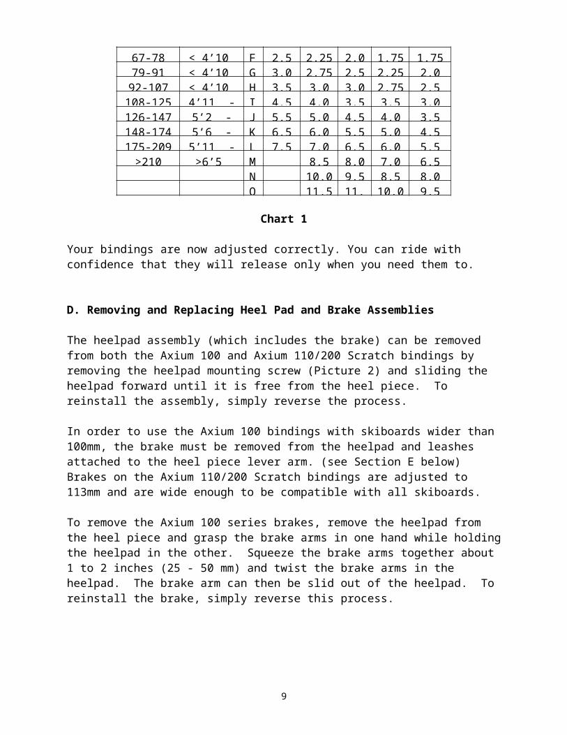
67-78 < 4’10” F 2.5 2.25 2.0 1.75 1.7579-91 < 4’10” G 3.0 2.75 2.5 2.25 2.0
92-107 < 4’10” H 3.5 3.0 3.0 2.75 2.5108-125 4’11” - I 4.5 4.0 3.5 3.5 3.0126-147 5’2” - J 5.5 5.0 4.5 4.0 3.5148-174 5’6” - K 6.5 6.0 5.5 5.0 4.5175-209 5’11” - L 7.5 7.0 6.5 6.0 5.5
>210 >6’5” M 8.5 8.0 7.0 6.5N 10.0 9.5 8.5 8.0O 11.5 11. 10.0 9.5
Chart 1
Your bindings are now adjusted correctly. You can ride with confidence that they will release only when you need them to.
D. Removing and Replacing Heel Pad and Brake Assemblies
The heelpad assembly (which includes the brake) can be removed from both the Axium 100 and Axium 110/200 Scratch bindings by removing the
7
heelpad mounting screw (Picture 2) and sliding the heelpad forward until it is free from the heel piece. To reinstall the assembly, simply reverse the process.
In order to use the Axium 100 bindings with skiboards wider than 100mm, the brake must be removed from the heelpad and leashes attached to the heel piece lever arm. (see Section E below) Brakes on the Axium 110/200 Scratch bindings are adjusted to 113mm and are wide enough to be compatible with all skiboards.
To remove the Axium 100 series brakes, remove the heelpad from the heel piece and grasp the brake arms in one hand while holding the heelpad in the other. Squeeze the brake arms together about 1 to 2 inches (25 - 50 mm) and twist the brake arms in the heelpad. The brake arm can then be slid out of the heelpad. To reinstall the brake, simply reverse this process.
E. Using Leashes With Axium 100 BindingsTo install leashes on the Axium 100 bindings, stick the leash lanyard through the large hole in the heel piece lever arm (see Picture 7) and pass the whole leash through the loop in the lanyard.
Picture 7
F. Pro Riser Dual MountThe Pro Series risers are set up with a "Dual Mount" system that allows them to be used on both 4cm x 4cm mount skiboards as well as boards that utilize a 4cm x 10cm mounting pattern. (see Picture 8) The risers are provided with "dummy" mounting screws that cover the mounting holes that are not being used. These screws may be either metal or black plastic. When changing from one mounting pattern to the other, simply remove the dummy screws,
8
move the metal mounting screws to the holes that the dummy screws were in and put the dummy screws in the old mounting holes.
Picture 8
9