· XLS file · Web view2015-10-08 · Added Phased PPAP requirements to industry Part Submission Warrant Added Capacity Requirements and Demonstrated Capacity sections Formatting
39
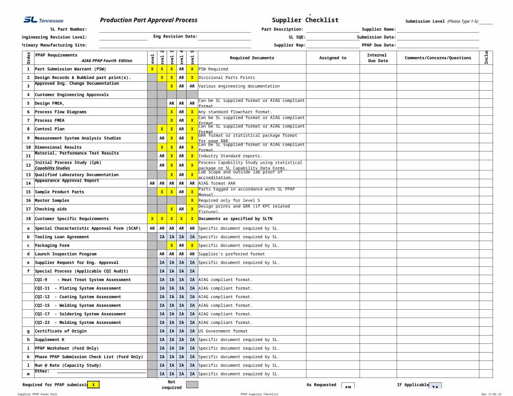
Supplier PPAP Forms Pack PPAP Supplier Checklist Rev 11-01-13 Production Part Approval Process SL Part Number: Part Description: Supplier Name: Engineering Revision Level: Eng Revision Date: SL SQE: Submission Date: Primary Manufacturing Site: Supplier Rep: PPAP Due Date: Order Level 1 evel 2 evel 3 evel 4 evel 5 Required Documents Assigned to Comments/Concerns/Questions Includ 1 Part Submission Warrant (PSW) X X X AR X PSW Required 2 Design Records & Bubbled part print(s). X X AR X Divisional Parts Prints 3 X AR AR Various engineering documentation 4 Customer Engineering Approvals 5 AR AR AR 6 Process Flow Diagrams X AR X Any standard flowchart format. 7 Process FMEA X AR X 8 Control Plan X X AR X 9 Measurement System Analysis Studies AR X AR X 10 Dimensional Results X X AR X 11 AR X AR X Industry Standard reports. 12 AR X AR X 13 Qualified Laboratory Documentation X AR X 14 AR AR AR AR AR AIAG format AAR 15 Sample Product Parts X X AR X 16 Master Samples X Required only for level 5 17 Checking aids X AR X 18 Customer Specific Requirements X X X X X Documents as specified by SLTN a Special Characteristic Approval Form (SCAF) AR AR AR AR AR Specific document required by SL. b Tooling Loan Agreement IA IA IA IA Specific document required by SL. c Packaging Form X AR X Specific document required by SL. d Launch Inspection Program AR AR AR AR Supplier’s preferred format e Supplier Request for Eng. Approval IA IA IA IA Specific document required by SL. f Special Process (Applicable CQI Audit) IA IA IA IA CQI-9 - Heat Treat System Assessment IA IA IA IA AIAG compliant format. CQI-11 - Plating System Assessment IA IA IA IA AIAG compliant format. CQI-12 - Coating System Assessment IA IA IA IA AIAG compliant format. CQI-15 - Welding System Assessment IA IA IA IA AIAG compliant format. CQI-17 - Soldering System Assessment IA IA IA IA AIAG compliant format. CQI-23 - Molding System Assessment IA IA IA IA AIAG compliant format. g Certificate of Origin IA IA IA IA US Government format h Supplement K IA IA IA IA Specific document required by SL. i PPAP Worksheet (Ford Only) IA IA IA IA Specific document required by SL. k Phase PPAP Submission Check List (Ford Only) IA IA IA IA Specific document required by SL. l Run @ Rate (Capacity Study) IA IA IA IA Specific document required by SL. m IA IA IA IA Specific document required by SL. Required for PPAP submissio X As Requested IF Applicable Supplier Checklist Submission Level (Please Type 1-5): PPAP Requirements AIAG PPAP Fourth Edition Internal Due Date Approved Eng. Change Documentation Design FMEA, Can be SL supplied format or AIAG compliant format. Can be SL supplied format or AIAG compliant format. Can be SL supplied format or AIAG compliant format. GRR format or statistical package format for gage R&R. Can be SL supplied format or AIAG compliant format. Material, Performance Test Results Initial Process Study (Cpk) Capability Studies Process Capability Study using statistical package or SL Capability Data Forms. Lab Scope and outside lab proof of accreditation. Appearance Approval Report Parts tagged in accordance with SL PPAP Manual. Design prints and GRR (if KPC related fixture). Other: ' ' Not required IA AR
Supplier PPAP Forms Pack PPAP Supplier Checklist Rev 11-01-13
Production Part Approval ProcessSL Part Number: Part Description: Supplier Name:
Engineering Revision Level: Eng Revision Date: SL SQE: Submission Date:
Primary Manufacturing Site: Supplier Rep: PPAP Due Date:O
rder
Leve
l 1
Leve
l 2
Leve
l 3
Leve
l 4
Leve
l 5
Required Documents Assigned to Comments/Concerns/Questions
Incl
uded
1 Part Submission Warrant (PSW) X X X AR X PSW Required
2 Design Records & Bubbled part print(s). X X AR X Divisional Parts Prints
3 Approved Eng. Change Documentation X AR AR Various engineering documentation
4 Customer Engineering Approvals
5 AR AR AR Can be SL supplied format or AIAG compliant format.
6 Process Flow Diagrams X AR X Any standard flowchart format.
7 Process FMEA X AR X Can be SL supplied format or AIAG compliant format.
8 Control Plan X X AR X Can be SL supplied format or AIAG compliant format.
9 Measurement System Analysis Studies AR X AR X GRR format or statistical package format for gage R&R.
10 Dimensional Results X X AR X Can be SL supplied format or AIAG compliant format.
11 Material, Performance Test Results AR X AR X Industry Standard reports.
12 AR X AR X
13 Qualified Laboratory Documentation X AR X Lab Scope and outside lab proof of accreditation.
14 Appearance Approval Report AR AR AR AR AR AIAG format AAR
15 Sample Product Parts X X AR X Parts tagged in accordance with SL PPAP Manual.
16 Master Samples X Required only for level 5
17 Checking aids X AR X Design prints and GRR (if KPC related fixture).
18 Customer Specific Requirements X X X X X Documents as specified by SLTN
a Special Characteristic Approval Form (SCAF) AR AR AR AR AR Specific document required by SL.
b Tooling Loan Agreement IA IA IA IA Specific document required by SL.
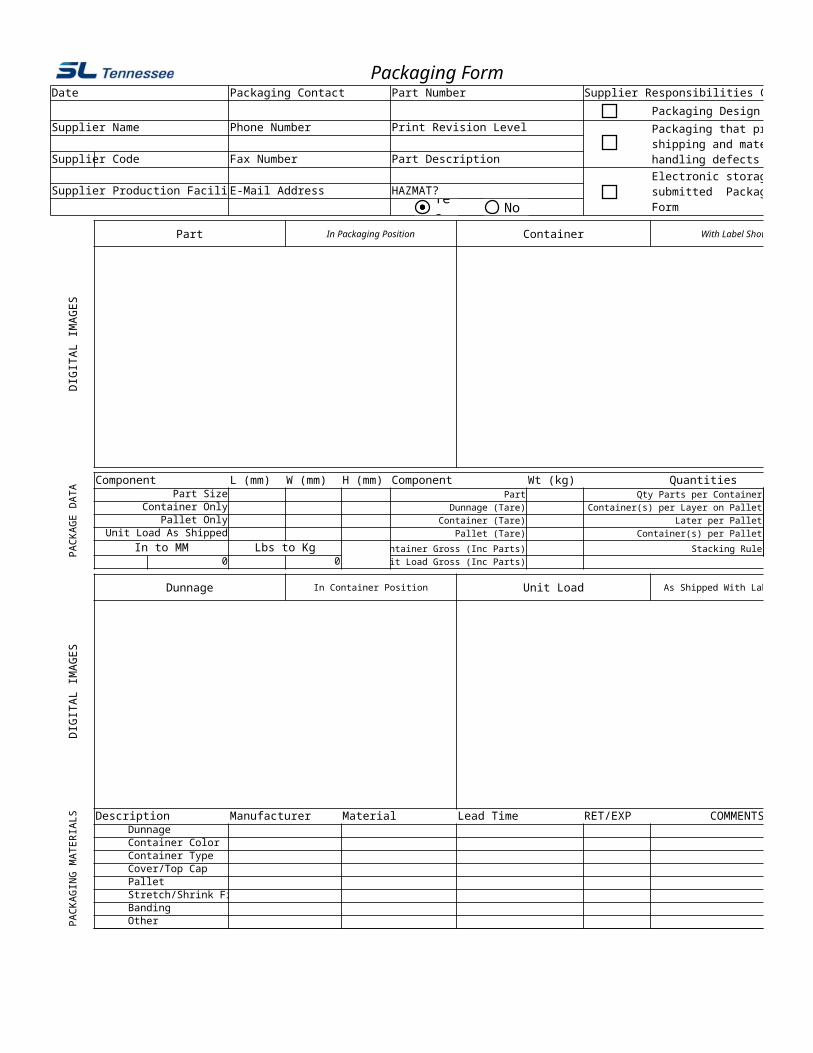
c Packaging Form X AR X Specific document required by SL.
d Launch Inspection Program AR AR AR AR Supplier’s preferred format
e Supplier Request for Eng. Approval IA IA IA IA Specific document required by SL.
f Special Process (Applicable CQI Audit) IA IA IA IA
CQI-9 - Heat Treat System Assessment IA IA IA IA AIAG compliant format.
CQI-11 - Plating System Assessment IA IA IA IA AIAG compliant format.
CQI-12 - Coating System Assessment IA IA IA IA AIAG compliant format.
CQI-15 - Welding System Assessment IA IA IA IA AIAG compliant format.
CQI-17 - Soldering System Assessment IA IA IA IA AIAG compliant format.
CQI-23 - Molding System Assessment IA IA IA IA AIAG compliant format.
g Certificate of Origin IA IA IA IA US Government format
h Supplement K IA IA IA IA Specific document required by SL.
i PPAP Worksheet (Ford Only) IA IA IA IA Specific document required by SL.
k Phase PPAP Submission Check List (Ford Only) IA IA IA IA Specific document required by SL.
l Run @ Rate (Capacity Study) IA IA IA IA Specific document required by SL.
m IA IA IA IA Specific document required by SL.
Required for PPAP submission X Not required As Requested IF Applicable
Submission Requirements - Supplier Checklist Submission Level (Please Type 1-5):
PPAP Requirements AIAG PPAP Fourth Edition
Internal Due Date
Design FMEA,
Initial Process Study (Cpk)Capability Studies
Process Capability Study using statistical package or SL Capability Data Forms.
Other: ' '
IAAR
Supplier PPAP Forms Pack PSW_Hyundai KIA Rev: 11-01-13
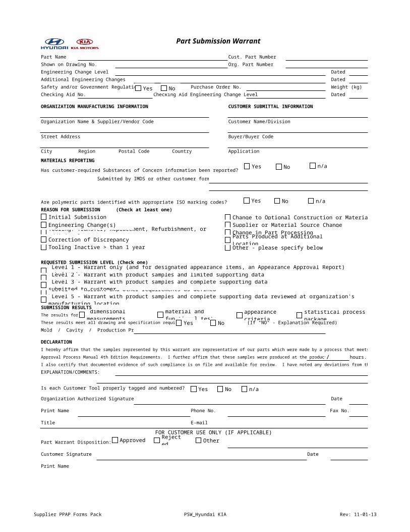
Part Submission Warrant
Part Name Cust. Part Number
Shown on Drawing No. Org. Part Number
Engineering Change Level Dated
Additional Engineering Changes Dated
Safety and/or Government Regulation Purchase Order No. Weight (kg)
Checking Aid No. Checking Aid Engineering Change Level Dated
ORGANIZATION MANUFACTURING INFORMATION CUSTOMER SUBMITTAL INFORMATION
Organization Name & Supplier/Vendor Code Customer Name/Division
Street Address Buyer/Buyer Code
City Region Postal Code Country Application
MATERIALS REPORTING
Has customer-required Substances of Concern information been reported?
Submitted by IMDS or other customer format:
Are polymeric parts identified with appropriate ISO marking codes?
REASON FOR SUBMISSION (Check at least one)
REQUESTED SUBMISSION LEVEL (Check one)
SUBMISSION RESULTSThe results for
These results meet all drawing and specification requirements: (If "NO" - Explanation Required)
Mold / Cavity / Production Process
DECLARATIONI hereby affirm that the samples represented by this warrant are representative of our parts which were made by a process that meets all Production Part
Approval Process Manual 4th Edition Requirements. I further affirm that these samples were produced at the production rate of / hours.I also certify that documented evidence of such compliance is on file and available for review. I have noted any deviations from the declaration below.
EXPLANATION/COMMENTS:
Is each Customer Tool properly tagged and numbered?
Organization Authorized Signature Date
Print Name Phone No. Fax No.
Title E-mail
FOR CUSTOMER USE ONLY (IF APPLICABLE)
Part Warrant Disposition:
Customer Signature Date
Print Name
Yes No
Yes No n/a
Initial Submission
Tooling: Transfer, Replacement, Refurbishment, or additional
Tooling Inactive > than 1 year
Change to Optional Construction or MaterialEngineering Change(s)
Correction of Discrepancy
Supplier or Material Source ChangeChange in Part Processing
Other - please specify belowParts Produced at Additional Location
Level 1 - Warrant only (and for designated appearance items, an Appearance Approval Report) submitted to customer.
Level 4 - Warrant and other requirements as defined by customer.
Level 2 - Warrant with product samples and limited supporting data submitted to customer. Level 3 - Warrant with product samples and complete supporting data submitted to customer. Level 5 - Warrant with product samples and complete supporting data reviewed at organization's manufacturing location.
Yes
dimensional measurements
material and functional tests
appearance criteria statistical process package
Yes No
Yes No n/a
Approved
Rejected Other
Yes No n/a
Supplier PPAP Forms Pack PSW_Hyundai KIA Rev: 11-01-13
Other - please specify below
statistical process package
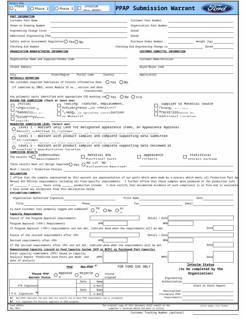
PPAP Submission WarrantPART INFORMATIONCustomer Part Name Customer Part Number
Shown on Drawing Number Organization Part Number
Engineering Change Level Dated
Additional Engineering Changes Dated
Safety and/or Government Regulation Purchase Order Number Weight (kg)
Checking Aid Number Checking Aid Engineering Change Level Dated
ORGANIZATION MANUFACTURING INFORMATION CUSTOMER SUBMITTAL INFORMATION
Organization Name and Supplier/Vendor Code Customer Name/Division
Street Address Buyer/Buyer Code
City State/Region Postal code Country ApplicationMATERIALS REPORTINGHas customer-required Substances of Concern information been reported?
Are polymeric parts identified with appropriate ISO marking codes?
Level 2 - Warrant with product samples and limited supporting data submitted to customer.
Level 4 - Warrant and other requirements as defined by customer.
SUBMISSION RESULTS
The results for
These results meet all design requirements
Mold / Cavity / Production Process
DECLARATIONI affirm that the samples represented by this warrant are representative of our parts which were made by a process which meets all Production Part Approval ProcessManual 4th Edition requirements including all Ford-specific requirements. I further affirm that these samples were produced at the production rate of ________ / _______ hours using _______ production streams. I also certify that documented evidence of such compliance is on file and is available for review. I have noted any exceptions from this declaration below.EXPLANATION/COMMENTS
Organization Authorized Signature Print Name Date
Title Phone Fax Email
Is each Customer Tool properly tagged and numbered?
Capacity RequirementsSource of the Program Approval requirements Detail / Date
Program Approval (<PA>) Requirements APW MPW
If Program Approval (<PA>) requirements are not met, indicate date when the requirements will be met Date
Source of the revised requirements after <PA> Detail / Date
Revised requirements after <PA> APW MPW
If the revised requirements after <PA> are not met, indicate date when the requirements will be met Date
Demonstrated Capacity (record in Ford Capacity System [GCP or MCPV] as Purchased Part Capacity)
APPC MPPC Date
FOR FORD USE ONLY
STA SignatureDate Name
e-mail Alert or Alert ReportDate Name
e-mail
Customer Tracking Number (optional)
Submitted by IMDS or other customer format(If submited by IMDS, enter Module ID no., version and date transmitted)
REASON FOR SUBMISSION (Check at least one)
REQUESTED SUBMISSION LEVEL (Select one)
Enter capacity commitment (PPC) based on Capacity Analysis Report "Predicted Good Parts per Week" and date of analysis
PPAP Non-PPAP a/ Interim Status
(to be completed by the Organization) Phased PPAP Warrant Status
Interim Accepted
Engineering Authorization
.
P.D. Signature /b .
Description: (Incomplete PPAP
Requirements)a/ Non-PPAP indicates the part does not satisfy one or more PPAP requirements and is incompleteb/ P.D. signature for Priority suppliers on GPDS programs
Ford GPPSS1May 2013
The original copy of this document shall remain at thesupplier's location while the part is active
Letter paper size format
Other - please specify
Parts produced at Additional Location
Change in Part Processing
Supplier or Material Source Change
Change to Optional Construction or Material
Tooling Inactive > than 1 year Correction of
Discrepancy
Tooling: Transfer, Replacement, Refurbishment, or additional Engineering
Change(s)
Initial submission
statistical process package
appearance criteria
material and functional tests
dimensional measurements,
Yes No n/a
Level 1 - Warrant only (and for designated appearance items, an Appearance Approval Report) submitted to customer. Level 3 - Warrant with product samples and complete supporting data submitted to customer. Level 5 - Warrant with product samples and complete supporting data reviewed at supplier's manufacturing location.
Phase 1 Phase 2 Phase 3
Select One
Yes No
Approved
Rejected
Yes No n/a
Yes
Yes
No (If "No" - Explanation Required)
Interim (Non-PPAP)
No
Q14
Enter the actual weight in kilograms to four decimal places unless otherwise specified by the customer
C28
Enter "IMDS" or "Other Customer Format" as appropriate. If submitted via IMDS include: Module ID number, Version number, Date Transmitted to the customer, and all other information as required by the customer specifics. If submitted via other customer format, enter the date the customer confirmation was received.
C50
Identify the specific cavities, molds or line for which the evaluation was conducted
H69
Select type of source of capacity requirements at the <PA> milestone from pull down menu
M69
Enter specific details of the source of the <PA> capacity requirements. For example, tool order number and date, CPA and date, etc.
I71
Enter the <PA> specified Average Production Weekly (APW) capacity requirements validated for this submission
N71
Enter the <PA> specified Maximum Production Weekly (MPW) capacity requirements validated for this submission
H74
Select type of source of revised capacity requirements after the <PA> milestone from pull down menu
M74
Enter specific details of the source of the capacity requirements revised after <PA>. For example, amended tool order number and date, updated WebQuote entry and date, etc.
I76
Enter the Average Production Weekly (APW) capacity requirements revised after <PA>
N76
Enter the Maximum Production Weekly (MPW) capacity requirements revised after <PA>
I79
Enter the APW the supplier is committing to, based on the "Predicted Good Parts per Week" field on the Capacity Analysis Report
N79
Enter the MPW the supplier is committing to, based on the "Predicted Good Parts per Week" field on the Capacity Analysis Report
Supplier PPAP Forms Pack SAFFPage 5 of 30 Rev: 11-01-13
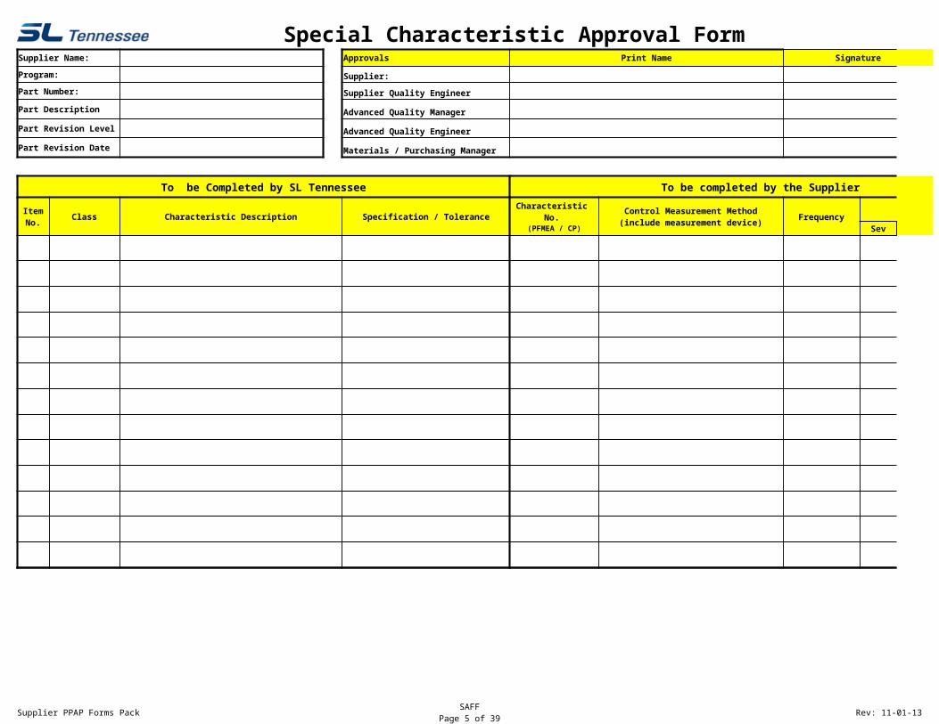
Special Characteristic Approval FormSupplier Name: Approvals Print Name Signature Approval Date
To be Completed by SL Tennessee To be completed by the Supplier
Class Characteristic Description Specification / TolerancePFMEA - RPN
Sev Occ Det
ItemNo.
Characteristic No.
(PFMEA / CP)
Control Measurement Method(include measurement device) Frequency
Supplier PPAP Forms Pack SAFFPage 6 of 30 Rev: 11-01-13
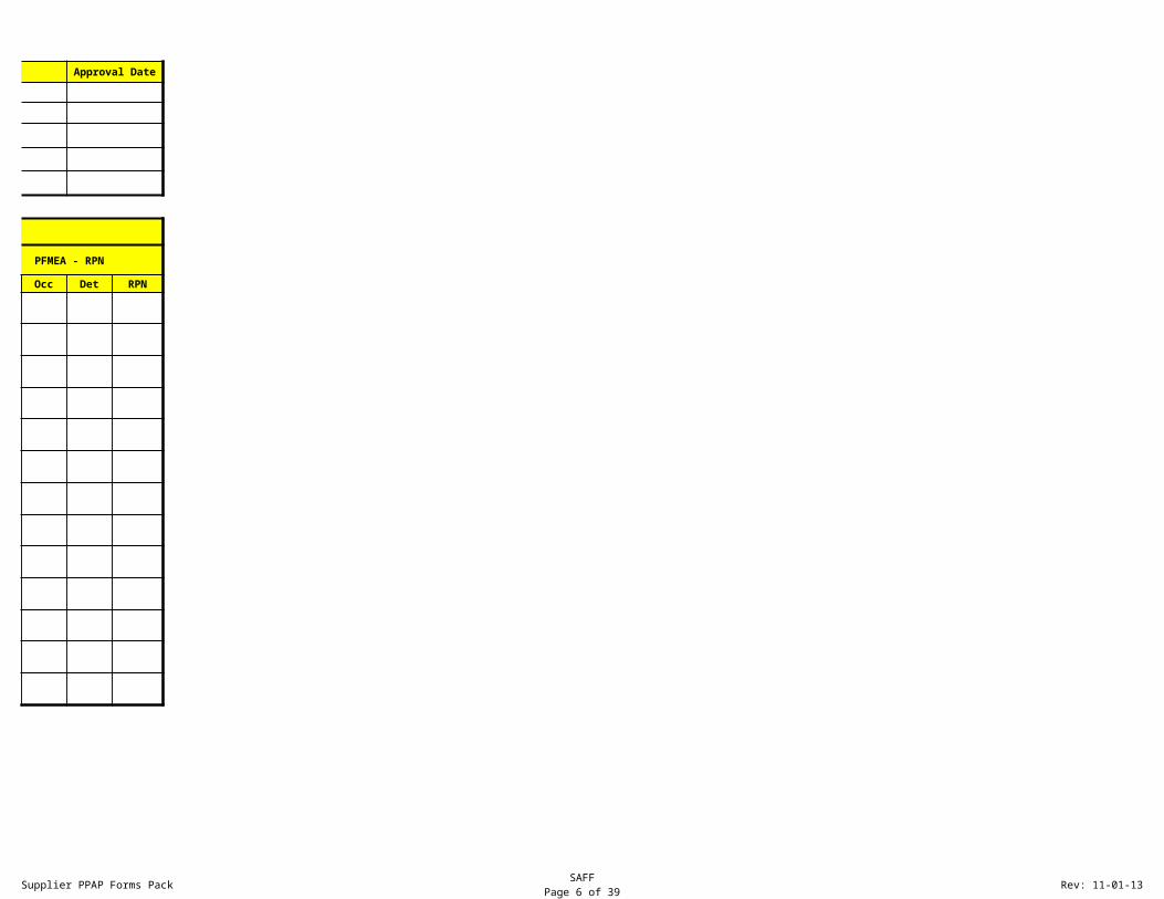
Special Characteristic Approval FormApproval Date
To be completed by the Supplier
PFMEA - RPN
RPN
Supplier PPAP Forms Pack Process FlowPage 7 of 30 Rev: 11-01-13
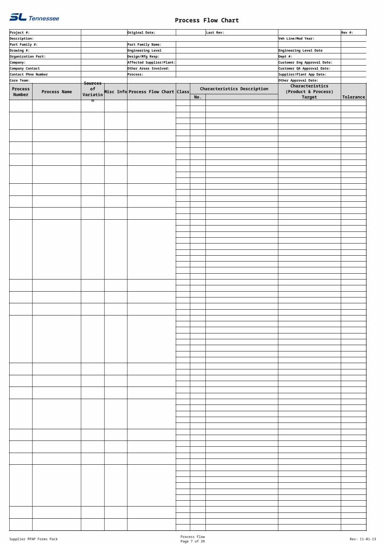
Process Flow Chart
Project #: Original Date: Last Rev: Rev #:
Description: Veh Line/Mod Year:
Part Family #: Part Family Name:
Drawing #: Engineering Level Engineering Level Date
Organization Part: Design/Mfg Resp: Dept #:
Company: Affected Supplier/Plant: Customer Eng Approval Date:
Company Contact Other Areas Involved: Customer QA Approval Date:
Contact Phne Number Process: Supplier/Plant App Date:
Core Team: Other Approval Date:
Process Name Misc Info Process Flow Chart ClassCharacteristics Description
No. Target Tolerance GD&T
Process Number
Sources of
Variation
Characteristics(Product & Process)
Supplier PPAP Forms Pack Process FlowPage 8 of 30 Rev: 11-01-13
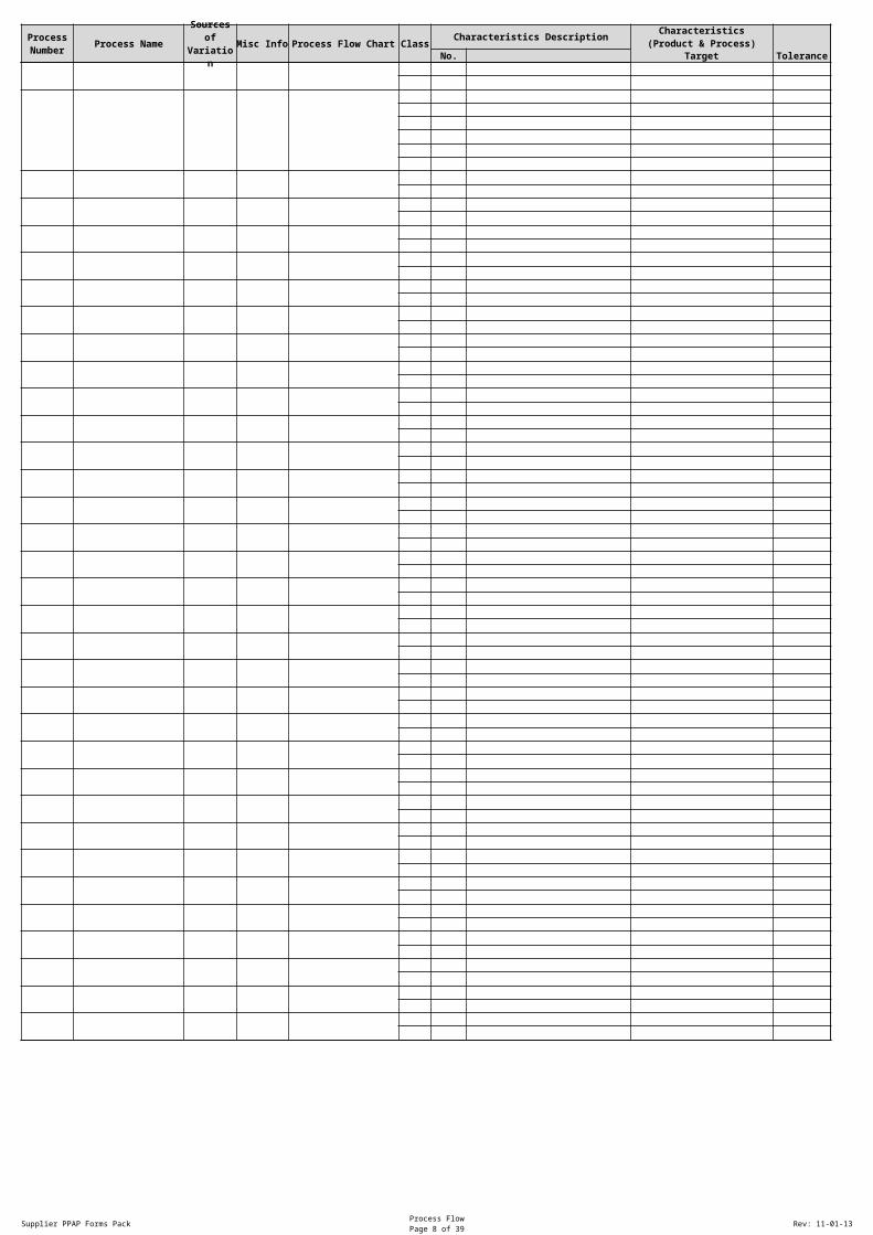
Process Name Misc Info Process Flow Chart ClassCharacteristics Description
No. Target Tolerance GD&T
Process Number
Sources of
Variation
Characteristics(Product & Process)
Page 9 of 30
Supplier PPAP Forms Pack Control PlanPage 9 of 30 Rev: 11-01-13
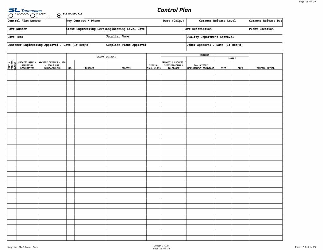
Control Plan
Control Plan Number Key Contact / Phone Date (Orig.) Current Release Level Current Release Date
Part Number Latest Engineering Level Engineering Level Date Part Description Plant Location
Core Team Supplier Name Quality Department Approval
Customer Engineering Approval / Date (If Req'd) Supplier Plant Approval Other Approval / Date (If Req'd)
CHARACTERISTICSMETHODS
CONTROL METHOD
SAMPLE
NO. PRODUCT PROCESS SIZE FREQPART
/ P
ROCE
SS
NU
MBE
R
PROCESS NAME / OPERATION
DESCRIPTION
MACHINE DEVICES / JIG / TOOLS FOR
MANUFACTURINGSPECIAL
CHAR. CLASS
PRODUCT / PROCESS / SPECIFICATION /
TOLERANCEEVALUATION/
MEASUREMENT TECHNIQUE
Prototype
Pre-Launch
Production
D3
This is the key quality person responsible for developing and leading the control plan strategy.
A4
This is the internal document number used to track and control the Control Plan.
H4
This is the date of original release of the control plan for the part number.
I4
This is the Revision level of the most current CONTROL PLAN release.
L4
Date the current control plan was released or became effective.
D5
Enter the most current revision level from the drawing.
F5
Enter the most current revision level date from the drawing.
G5
Enter the description of the part on the Cooper print.
A6
Enter the part number and the most current revision level.
A8
List all key team members involved in the process and the control plan. List names, numbers and other contact information.
F8
Full Name of Supplier
A10
Customer or SL Engineering approval (if required)
F10
Supplier Management signature of the control plan indicating executive level approval of the control plan.
A12
The item number is usually referenced from the process flow chart. If multiple part numbers exist (assembly) list the individual part numbers and their processes accordingly.
B12
All steps in the manufacturing of a system, subsystem or component are described. Identify the process/operation that best describes the activity on each line.
C12
For each operation that is described, identify the processing equipment, machine, device, jig or other tool for manufacturing as appropriate.
D12
A distinguishing feature, dimension or property of a process or it's output on which variable or attribute data can be collected.
G12
Use the appropriate characteristic as defined by the Cooper Division you are supplying.
H12
Systematic plan for controlling a process.
L12
Brief description of how the operation will be controlled, including procedure numbers where applicable. Should be based on effective analysis of the process. Various methods can be used from additional inspection to SPC or error proofing. The method of control should be clinically evaluated for effectiveness of process control.
H13
Specification/tolerance may be obtained from various engineering documents such as drawings, specifications etc..
I13
Measurement system being used to check the specification or tolerance. This could include gages, fixtures, tools and or test equipment required to measure the part/process/manufacturing equipment. A measurement system analysis should be done to ensure control of monitoring and measuring devices prior to relying on a measurement system.
J13
When sampling is required list the corresponding sample size and frequency.
D14
Cross reference number from all applicable documents such as FMEAS, process flows etc..
E14
Product characteristics are the features or properties of a part that are described on the drawings or other primary engineering information. The Core Team should identify the special Product Characteristics from all sources. All special characteristics should be listed on the Control Plan.
F14
Process Characteristics are the process variables that have a cause and effect relationship with the identified Product Characteristic. A Process Characteristic can only be measured at the time it occurs. The Core Team should identify Process Characteristics for which variation must be controlled to minimize variation. There could be one or more Process Characteristics listed for each Product Characteristic. In some processes one Process Characteristic may affect several Product Characteristics.
Page 10 of 30
Supplier PPAP Forms Pack Control PlanPage 10 of 30 Rev: 11-01-13
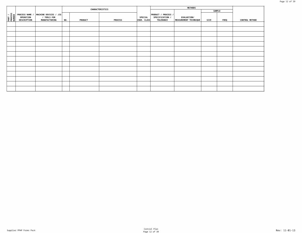
CHARACTERISTICSMETHODS
CONTROL METHOD
SAMPLE
NO. PRODUCT PROCESS SIZE FREQPART
/ P
ROCE
SS
NU
MBE
R
PROCESS NAME / OPERATION
DESCRIPTION
MACHINE DEVICES / JIG / TOOLS FOR
MANUFACTURINGSPECIAL
CHAR. CLASS
PRODUCT / PROCESS / SPECIFICATION /
TOLERANCEEVALUATION/
MEASUREMENT TECHNIQUE
A12
The item number is usually referenced from the process flow chart. If multiple part numbers exist (assembly) list the individual part numbers and their processes accordingly.
B12
All steps in the manufacturing of a system, subsystem or component are described. Identify the process/operation that best describes the activity on each line.
C12
For each operation that is described, identify the processing equipment, machine, device, jig or other tool for manufacturing as appropriate.
D12
A distinguishing feature, dimension or property of a process or it's output on which variable or attribute data can be collected.
G12
Use the appropriate characteristic as defined by the Cooper Division you are supplying.
H12
Systematic plan for controlling a process.
L12
Brief description of how the operation will be controlled, including procedure numbers where applicable. Should be based on effective analysis of the process. Various methods can be used from additional inspection to SPC or error proofing. The method of control should be clinically evaluated for effectiveness of process control.
H13
Specification/tolerance may be obtained from various engineering documents such as drawings, specifications etc..
I13
Measurement system being used to check the specification or tolerance. This could include gages, fixtures, tools and or test equipment required to measure the part/process/manufacturing equipment. A measurement system analysis should be done to ensure control of monitoring and measuring devices prior to relying on a measurement system.
J13
When sampling is required list the corresponding sample size and frequency.
D14
Cross reference number from all applicable documents such as FMEAS, process flows etc..
E14
Product characteristics are the features or properties of a part that are described on the drawings or other primary engineering information. The Core Team should identify the special Product Characteristics from all sources. All special characteristics should be listed on the Control Plan.
F14
Process Characteristics are the process variables that have a cause and effect relationship with the identified Product Characteristic. A Process Characteristic can only be measured at the time it occurs. The Core Team should identify Process Characteristics for which variation must be controlled to minimize variation. There could be one or more Process Characteristics listed for each Product Characteristic. In some processes one Process Characteristic may affect several Product Characteristics.
Page 11 of 30
Supplier PPAP Forms Pack Control PlanPage 11 of 30 Rev: 11-01-13
Control Plan
Supplier Code
Plant Location
Quality Department Approval
Other Approval / Date (If Req'd)
REACTION PLAN
L6
Location of the current plant.
I8
Signature of author or quality approval of control plan.
I10
Any additional approvals required.
M12
The reaction plan specifies the corrective actions necessary to avoid producing nonconforming products or operating out of control. The actions should normally be the responsibility of the people closest to the process.
Page 12 of 30
Supplier PPAP Forms Pack Control PlanPage 12 of 30 Rev: 11-01-13
REACTION PLAN
M12
The reaction plan specifies the corrective actions necessary to avoid producing nonconforming products or operating out of control. The actions should normally be the responsibility of the people closest to the process.
Page 13 of 30
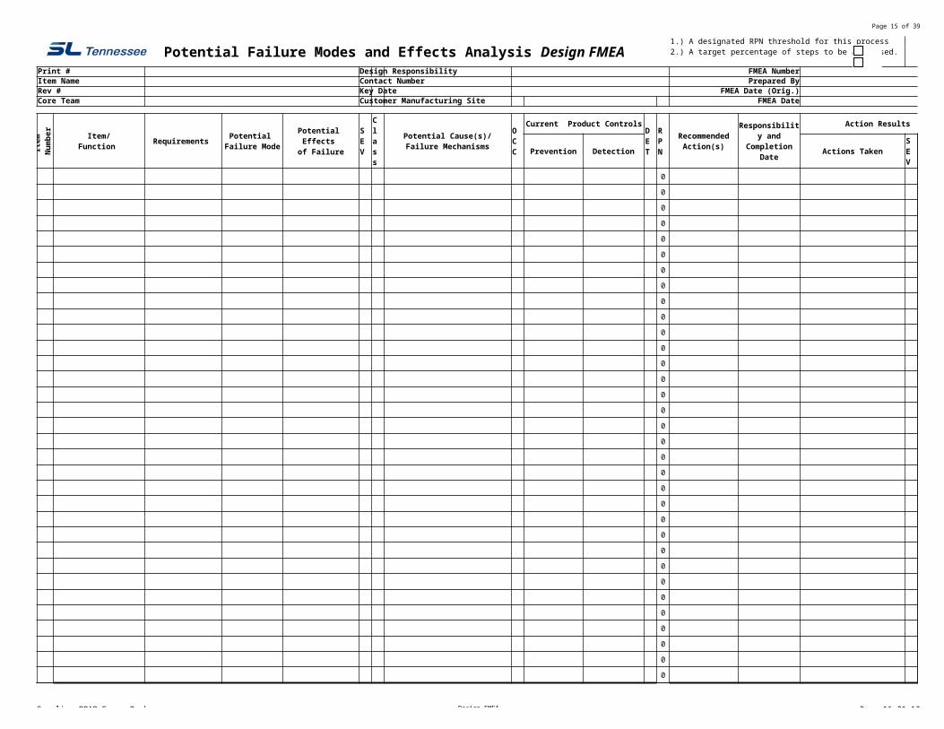
Supplier PPAP Forms Pack Design FMEA Rev: 11-01-13
Print # Design Responsibility FMEA NumberItem Name Contact Number Prepared ByRev # Key Date FMEA Date (Orig.)Core Team Customer Manufacturing Site FMEA Date
Item
Num
ber
Requirements
Current Product Controls Action Results
Prevention Detection Actions Taken
0 0
0 0
0 0
0 0
0 0
0 0
0 0
0 0
0 0
0 0
0 0
0 0
0 0
0 0
0 0
0 0
0 0
0 0
0 0
0 0
0 0
0 0
0 0
0 0
0 0
0 0
0 0
0 0
0 0
0 0
0 0
0 0
0 0
Potential Failure Modes and Effects Analysis Design FMEAPlease indicate EITHER: 1.) A designated RPN threshold for this process 2.) A target percentage of steps to be addressed.
Item/Function
Potential Failure Mode
Potential Effects of Failure
SEV
Class
Potential Cause(s)/Failure Mechanisms
OCC
DET
RPN
RecommendedAction(s)
Responsibility and Completion
DateSEV
OCC
DET
RPN
N1
Either a target percentage or RPN threshold is determined by the organization owning the product. A "target percentage" means that regardless of the RPN number, your organization will address a percentage of the highest RPN line item steps in the process WITH ADDITIONAL ACTIONS to reduce overall risk. For example, with a specific product your internal target percentage is to address the top 25% highest RPN values with additional action. This is the Cooper recommended way to address overall risk because it drives improvement regardless of RPN value. Some organizations designate an "RPN threshold" or cutoff value. This means that you will take action beyond a certain value. For example if your RPN threshold value is 50, then any items in the DFMEA that have a calculated RPN at 50 or higher require the "actions taken" section to addressed. Note: Special attention should always be given to any severity 8 -10 items.
Q1
Number for either percentage or threshold.
C2
SL Part Number as stated on SL Print.
I2
Department group or supplier name responsible for the item.
P2
Insert FMEA Document Number
C3
Name of the System or component for which the process is being analyzed.
I3
Phone number or email of person responsible for completing Information.
P3
Company and person responsible for preparing DFMEA
C4
Most recent revision off of SL Print
I4
Enter the initial due date of the DFMEA which should not exceed start of production.
P4
Enter the date the original DFMEA was completed.
C5
Identify the Core Team members for the DFMEA activity.
P5
Insert date of latest revision to DFMEA
A7
The item number is may be referenced from the process flow chart or control plan. If multiple part numbers exist (assembly) list the individual part numbers and their functions
B7
Enter a description of each item number here.
C7
Enter the requirements of each item/function being analyzed.
D7
In what ways might the product/function potentially fail to meet the part requirements and/or function intent? List each potential failure mode. There can be multiple failure modes for each process step.
E7
What is the effect of each failure mode on the outputs and/or customer requirements? The customer could be the next operation, subsequent operations, another division or the end user. Typical failure should be stated in terms of part performance.
F7
SEVERITY EFFECT SEVERITY OF EFFECT ON PRODUCT RANK Failure to meet safety Potential failure mode affects safe product operation 10 and/or regulatory and/or involves noncompliance with regulation WITHOUT warning. requirements noncompliance with regulation Potential failure mode affects safe product operation 9 and/or involves noncompliance with warning. Loss or degradation Loss of primary function(product inoperable/does not 8 of primary function. affect safe operation). Degradation of primary function (product operable but 7 at a reduced level of performance). Loss of degradation Loss of secondary function (product operable but comfort 6 of secondary function. convenience functions at a level. Degradation of secondary function (product operable, 5 but comfort convenience functions at a reduced level of performance. Annoyance Appearance or minor issue, product operable, 4 product does not conform and noticed by most customers (>75%). Appearance or minor issue, product does not conform, 3 and noticed by many customers(50%). Appearance or minor issue, product operable, product does not conform and noticed by discriminating customers.(<25%) 2 No effect No discernible effect. 1
G7
How Severe is the effect to the customer? Identified product characteristics!
H7
How can the failure occur? Describe in terms of something that can be corrected or controlled. Be specific. Try to identify the causes that directly impacts the failure mode, i.e., root causes.
I7
How often does the cause or failure mode occur? RATING LIKELIHOOD OF OCCURRENCE LABEL 10 ≥100 per thousand pieces ≥1 in 10 VERY HIGH 9 50 per thousand pieces 1 in 20 VERY HIGH 8 20 per thousand pieces 1 in 50 HIGH 7 10 per thousand pieces 1 in 100 HIGH 6 2 per thousand pieces 1 in 500 MODERATE 5 .5 per thousand pieces 1 in 2000 MODERATE 4 .1 per thousand pieces 1 in 10,000 MODERATE 3 .01 per thousand pieces 1 in 100,000 LOW 2 ≤.001 per thousand pieces 1 in 1000,000 LOW 1 Failure is eliminated thru preventive VERY LOW control See Chart Page 28 of PPAP Handbook for further information.
J7
What are the existing controls and procedures (inspection and test) that either prevent failure mode from occurring or detect the failure should it occur? The preferred approach is always prevention!
L7
Estimate how well can you detect cause or failure mode. Do not automatically presume that the detection is low because the occurrence is low. Assess the capability of the design controls to detect low frequency failure modes. Rank Opportunity For Detection Likelihood of Detection by Design Control Likelihood of Detection 10 No Detection Opportunity No current design control: Cannot detect or is not analyzed Almost impossible 9 Not likely to detect at any stage. Design analysis/detection controls have a weak detection Very Remote capability; Virtual Analysis is Not Correlated to expected actual operating conditions. 8 Post design freeze and prior to launch Product verification/validation after design freeze and prior to Remote launch with pass/fail testing 7 Post design freeze and prior to launch Product verification/validation after design freeze and prior to Very Low launch with pass/fail testing 6 Post design freeze and prior to launch Product verification/validation after design freeze and prior to Low launch with degradation testing. 5 Prior to design freeze Product validation prior to design freeze using pass/fail testing Moderate (reliability testing development or validation tests). 4 Prior to design freeze Product validation prior to design freeze using test to failure Moderately High (reliability testing development or validation tests) 3 Prior to design freeze Product validation prior to design freeze using degradation testing High (Reliability testing development or validation tests). will detect error and prevent processing 2 Virtual Analysis Correlated Design analysis/detection controls have a strong detection capability. Very High , Virtual analysis is highly correlated with actual or expected condition prior to a design freeze. 1 Detection not applicable; Error prevention as a result of product Almost Certain Failure prevention. Failure mode cannot occur because it is fully prevented through design solutions (proven design standards, best practice or common material).
M7
SEV x OCC x DET
N7
What are the actions for reducing the occurrence, or improving detection, or for identifying the root cause if it is unknown? Prevention actions are preferable to detection actions.
O7
Enter the name of the person who is responsible for the recommended action and the target date for completion.
J8
Eliminate the cause of the mechanism of failure from occurring or reduce its occurrence.
K8
Identify the existence of a cause, the resulting mechanism of failure either by analytical or physical methods before the item is released for production
P8
List the completed actions that are included in the recalculated RPN. Include the implementation date for any changes.
Q8
What is the new severity based on the action applied.
R8
What is the new Occurrence numbers based on the action taken.
S8
What is the new detection ranking based on the action taken. Has the detection improved?
T8
Recompute RPN after actions are complete.
Page 14 of 30
Supplier PPAP Forms Pack Process FMEAPage 14 of 30 Rev: 11-01-13
Print # Engineering Level: Engineering Level Date FMEA NumberPart Description Contact Number Revision No.Prepared By Design Responsibility Key Date FMEA Date (Orig.)Core Team Customer Manufacturing Site FMEA Date
Item
Num
ber
Requirements
Class
Current Product Controls
RPN
Action Results
No. Prevention Detection Actions Taken
0
0
0
0
0
0
0
0
0
0
0
0
0
0
0
0
0
0
0
0
0
0
0
0
0
0
0
0
0
0
0
0
0
0
0
0
0
Potential Failure Modes and Effects Analysis Design FMEAPlease indicate EITHER: 1.) A designated RPN threshold for this process 2.) A target percentage of steps to be addressed.
Item/Function
Potential Failure Mode
Potential Effects of Failure
SEV
Potential Cause(s)/Failure Mechanisms
OCC
DET
RecommendedAction(s)
Responsibility and Completion
DateSEV
OCC
DET
O1
Either a target percentage or RPN threshold is determined by the organization owning the product. A "target percentage" means that regardless of the RPN number, your organization will address a percentage of the highest RPN line item steps in the process WITH ADDITIONAL ACTIONS to reduce overall risk. For example, with a specific product your internal target percentage is to address the top 25% highest RPN values with additional action. This is the Cooper recommended way to address overall risk because it drives improvement regardless of RPN value. Some organizations designate an "RPN threshold" or cutoff value. This means that you will take action beyond a certain value. For example if your RPN threshold value is 50, then any items in the DFMEA that have a calculated RPN at 50 or higher require the "actions taken" section to addressed. Note: Special attention should always be given to any severity 8 -10 items.
R1
Number for either percentage or threshold.
F2
Enter the Engineering level from the drawing
J2
Enter the Engineering level date from the drawing
J3
Phone number or email of person responsible for completing Information.
C4
Department group or supplier name responsible for the item.
J4
Enter the initial due date of the PFMEA which should not exceed start of production.
A7
The item number is may be referenced from the process flow chart or control plan. If multiple part numbers exist (assembly) list the individual part numbers and their functions
B7
Enter a description of each item number here.
E7
In what ways might the product/function potentially fail to meet the part requirements and/or function intent? List each potential failure mode. There can be multiple failure modes for each process step.
F7
What is the effect of each failure mode on the outputs and/or customer requirements? The customer could be the next operation, subsequent operations, another division or the end user. Typical failure should be stated in terms of part performance.
G7
SEVERITY EFFECT SEVERITY OF EFFECT ON PRODUCT RANK Failure to meet safety Potential failure mode affects safe product operation 10 and/or regulatory and/or involves noncompliance with regulation WITHOUT warning. requirements noncompliance with regulation Potential failure mode affects safe product operation 9 and/or involves noncompliance with warning. Loss or degradation Loss of primary function(product inoperable/does not 8 of primary function. affect safe operation). Degradation of primary function (product operable but 7 at a reduced level of performance). Loss of degradation Loss of secondary function (product operable but comfort 6 of secondary function. convenience functions at a level. Degradation of secondary function (product operable, 5 but comfort convenience functions at a reduced level of performance. Annoyance Appearance or minor issue, product operable, 4 product does not conform and noticed by most customers (>75%). Appearance or minor issue, product does not conform, 3 and noticed by many customers(50%). Appearance or minor issue, product operable, product does not conform and noticed by discriminating customers.(<25%) 2 No effect No discernible effect. 1
H7
How Severe is the effect to the customer? Identified product characteristics!
I7
How can the failure occur? Describe in terms of something that can be corrected or controlled. Be specific. Try to identify the causes that directly impacts the failure mode, i.e., root causes.
J7
How often does the cause or failure mode occur? RATING LIKELIHOOD OF OCCURRENCE LABEL 10 ≥100 per thousand pieces ≥1 in 10 VERY HIGH 9 50 per thousand pieces 1 in 20 VERY HIGH 8 20 per thousand pieces 1 in 50 HIGH 7 10 per thousand pieces 1 in 100 HIGH 6 2 per thousand pieces 1 in 500 MODERATE 5 .5 per thousand pieces 1 in 2000 MODERATE 4 .1 per thousand pieces 1 in 10,000 MODERATE 3 .01 per thousand pieces 1 in 100,000 LOW 2 ≤.001 per thousand pieces 1 in 1000,000 LOW 1 Failure is eliminated thru preventive VERY LOW control See Chart Page 28 of PPAP Handbook for further information.
K7
What are the existing controls and procedures (inspection and test) that either prevent failure mode from occurring or detect the failure should it occur? The preferred approach is always prevention!
M7
Estimate how well can you detect cause or failure mode. Do not automatically presume that the detection is low because the occurrence is low. Assess the capability of the design controls to detect low frequency failure modes. Rank Opportunity For Detection Likelihood of Detection by Design Control Likelihood of Detection 10 No Detection Opportunity No current design control: Cannot detect or is not analyzed Almost impossible 9 Not likely to detect at any stage. Design analysis/detection controls have a weak detection Very Remote capability; Virtual Analysis is Not Correlated to expected actual operating conditions. 8 Post design freeze and prior to launch Product verification/validation after design freeze and prior to Remote launch with pass/fail testing 7 Post design freeze and prior to launch Product verification/validation after design freeze and prior to Very Low launch with pass/fail testing 6 Post design freeze and prior to launch Product verification/validation after design freeze and prior to Low launch with degradation testing. 5 Prior to design freeze Product validation prior to design freeze using pass/fail testing Moderate (reliability testing development or validation tests). 4 Prior to design freeze Product validation prior to design freeze using test to failure Moderately High (reliability testing development or validation tests) 3 Prior to design freeze Product validation prior to design freeze using degradation testing High (Reliability testing development or validation tests). will detect error and prevent processing 2 Virtual Analysis Correlated Design analysis/detection controls have a strong detection capability. Very High , Virtual analysis is highly correlated with actual or expected condition prior to a design freeze. 1 Detection not applicable; Error prevention as a result of product Almost Certain Failure prevention. Failure mode cannot occur because it is fully prevented through design solutions (proven design standards, best practice or common material).
N7
SEV x OCC x DET
O7
What are the actions for reducing the occurrence, or improving detection, or for identifying the root cause if it is unknown? Prevention actions are preferable to detection actions.
P7
Enter the name of the person who is responsible for the recommended action and the target date for completion.
K8
Eliminate the cause of the mechanism of failure from occurring or reduce its occurrence.
L8
Identify the existence of a cause, the resulting mechanism of failure either by analytical or physical methods before the item is released for production
Q8
List the completed actions that are included in the recalculated RPN. Include the implementation date for any changes.
R8
What is the new severity based on the action applied.
S8
What is the new Occurrence numbers based on the action taken.
T8
What is the new detection ranking based on the action taken. Has the detection improved?
Page 15 of 30
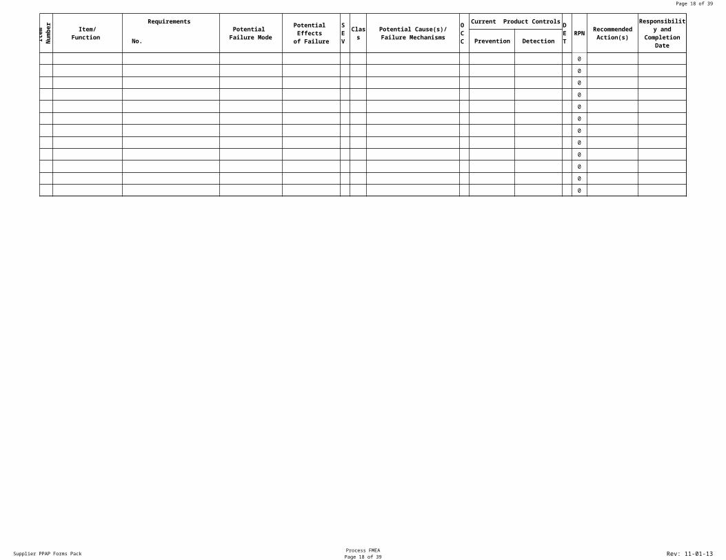
Supplier PPAP Forms Pack Process FMEAPage 15 of 30 Rev: 11-01-13
Item
Num
ber
Requirements
Class
Current Product Controls
RPN
Action Results
No. Prevention Detection Actions Taken
Item/Function
Potential Failure Mode
Potential Effects of Failure
SEV
Potential Cause(s)/Failure Mechanisms
OCC
DET
RecommendedAction(s)
Responsibility and Completion
DateSEV
OCC
DET
0
0
0
0
0
0
0
0
0
0
0
A7
The item number is may be referenced from the process flow chart or control plan. If multiple part numbers exist (assembly) list the individual part numbers and their functions
B7
Enter a description of each item number here.
E7
In what ways might the product/function potentially fail to meet the part requirements and/or function intent? List each potential failure mode. There can be multiple failure modes for each process step.
F7
What is the effect of each failure mode on the outputs and/or customer requirements? The customer could be the next operation, subsequent operations, another division or the end user. Typical failure should be stated in terms of part performance.
G7
SEVERITY EFFECT SEVERITY OF EFFECT ON PRODUCT RANK Failure to meet safety Potential failure mode affects safe product operation 10 and/or regulatory and/or involves noncompliance with regulation WITHOUT warning. requirements noncompliance with regulation Potential failure mode affects safe product operation 9 and/or involves noncompliance with warning. Loss or degradation Loss of primary function(product inoperable/does not 8 of primary function. affect safe operation). Degradation of primary function (product operable but 7 at a reduced level of performance). Loss of degradation Loss of secondary function (product operable but comfort 6 of secondary function. convenience functions at a level. Degradation of secondary function (product operable, 5 but comfort convenience functions at a reduced level of performance. Annoyance Appearance or minor issue, product operable, 4 product does not conform and noticed by most customers (>75%). Appearance or minor issue, product does not conform, 3 and noticed by many customers(50%). Appearance or minor issue, product operable, product does not conform and noticed by discriminating customers.(<25%) 2 No effect No discernible effect. 1
H7
How Severe is the effect to the customer? Identified product characteristics!
I7
How can the failure occur? Describe in terms of something that can be corrected or controlled. Be specific. Try to identify the causes that directly impacts the failure mode, i.e., root causes.
J7
How often does the cause or failure mode occur? RATING LIKELIHOOD OF OCCURRENCE LABEL 10 ≥100 per thousand pieces ≥1 in 10 VERY HIGH 9 50 per thousand pieces 1 in 20 VERY HIGH 8 20 per thousand pieces 1 in 50 HIGH 7 10 per thousand pieces 1 in 100 HIGH 6 2 per thousand pieces 1 in 500 MODERATE 5 .5 per thousand pieces 1 in 2000 MODERATE 4 .1 per thousand pieces 1 in 10,000 MODERATE 3 .01 per thousand pieces 1 in 100,000 LOW 2 ≤.001 per thousand pieces 1 in 1000,000 LOW 1 Failure is eliminated thru preventive VERY LOW control See Chart Page 28 of PPAP Handbook for further information.
K7
What are the existing controls and procedures (inspection and test) that either prevent failure mode from occurring or detect the failure should it occur? The preferred approach is always prevention!
M7
Estimate how well can you detect cause or failure mode. Do not automatically presume that the detection is low because the occurrence is low. Assess the capability of the design controls to detect low frequency failure modes. Rank Opportunity For Detection Likelihood of Detection by Design Control Likelihood of Detection 10 No Detection Opportunity No current design control: Cannot detect or is not analyzed Almost impossible 9 Not likely to detect at any stage. Design analysis/detection controls have a weak detection Very Remote capability; Virtual Analysis is Not Correlated to expected actual operating conditions. 8 Post design freeze and prior to launch Product verification/validation after design freeze and prior to Remote launch with pass/fail testing 7 Post design freeze and prior to launch Product verification/validation after design freeze and prior to Very Low launch with pass/fail testing 6 Post design freeze and prior to launch Product verification/validation after design freeze and prior to Low launch with degradation testing. 5 Prior to design freeze Product validation prior to design freeze using pass/fail testing Moderate (reliability testing development or validation tests). 4 Prior to design freeze Product validation prior to design freeze using test to failure Moderately High (reliability testing development or validation tests) 3 Prior to design freeze Product validation prior to design freeze using degradation testing High (Reliability testing development or validation tests). will detect error and prevent processing 2 Virtual Analysis Correlated Design analysis/detection controls have a strong detection capability. Very High , Virtual analysis is highly correlated with actual or expected condition prior to a design freeze. 1 Detection not applicable; Error prevention as a result of product Almost Certain Failure prevention. Failure mode cannot occur because it is fully prevented through design solutions (proven design standards, best practice or common material).
N7
SEV x OCC x DET
O7
What are the actions for reducing the occurrence, or improving detection, or for identifying the root cause if it is unknown? Prevention actions are preferable to detection actions.
P7
Enter the name of the person who is responsible for the recommended action and the target date for completion.
K8
Eliminate the cause of the mechanism of failure from occurring or reduce its occurrence.
L8
Identify the existence of a cause, the resulting mechanism of failure either by analytical or physical methods before the item is released for production
Q8
List the completed actions that are included in the recalculated RPN. Include the implementation date for any changes.
R8
What is the new severity based on the action applied.
S8
What is the new Occurrence numbers based on the action taken.
T8
What is the new detection ranking based on the action taken. Has the detection improved?
Page 16 of 30
Supplier PPAP Forms Pack Process FMEAPage 16 of 30 Rev: 11-01-13
Action Results
RPN
0
0
0
0
0
0
0
0
0
0
0
0
0
0
0
0
0
0
0
0
0
0
0
0
0
0
0
0
0
0
0
0
0
0
0
0
0
Q2
Insert FMEA Document Number
Q3
Company and person responsible for preparing PFMEA
Q4
Enter the date the original DFMEA was completed.
Q5
Insert date of latest revision to PFMEA
U8
Recompute RPN after actions are complete.
Page 17 of 30
Supplier PPAP Forms Pack Process FMEAPage 17 of 30 Rev: 11-01-13
Action Results
RPN
0
0
0
0
0
0
0
0
0
0
0
U8
Recompute RPN after actions are complete.
Page 18 of 30
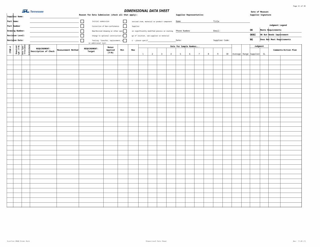
Supplier PPAP Forms Pack Dimensional Data Sheet Rev: 11-01-13
Date of Measurement:
Supplier Name:Reason for Data Submission (check all that apply): Supplier Representative: Supplier Signature
Part Name: New/revised item, material or product component Name Title
Part Number Correction of Non-conformance New Supplier Judgment Legend
Drawing Number: New/Revised drawing or other specification New or significantly modified process or routing Phone Number Email: OK Meets Requirements
Revision Level: Change to optional construction or material Change of location, sub-supplier or materialOKNI OK But Needs Improvement
Revision Date: Tooling: Transfer, replacement, refurbishment Other - please specify Date: Supplier Code: NG Does Not Meet Requirements
ITEM
#
Measurement Method Min Max
Data for Sample Number…..
Average Range
Judgment
Comments/Action Plan
1 2 3 4 5 6 7 8 9 10 Supplier SL
0.00
0.00
0.00
0.00
0.00
0.00
0.00
0.00
0.00
0.00
0.00
0.00
0.00
0.00
0.00
0.00
0.00
0.00
0.00
0.00
0.00
0.00
0.00
0.00
0.00
0.00
0.00
0.00
0.00
0.00
0.00
0.00
DIMENSIONAL DATA SHEET
Initial submission
or additional tool.
Requ
ired
Cpk
(Y/N
)
Data
Typ
e: V
=Var
iabl
e A
=Att
ribut
e
REQUIREMENT:Description of Check
REQUIREMENT:Target
Bonus Applied (Y/N)
D2
Full Name of Supplier
D3
Balloon Drawing Title
G3
Indicate the reason that the data is being submitted. There may be more than one reason.
O3
Name of Person Completing Report
S3
Title of Person Completing Report
W3
Signature of Supplier Representative
D4
SL Part number on the SL Part Print
D5
Drawing Number and Revision listed on accompanying balloon drawing
P5
Best Number to Reach Supplier Representative
S5
Supplier Representative Email Address
D6
Revision level on SL component level print.:
D7
Located either in engineering title block or revision matrix on component level print. This is the date the part was revised to the most recent rev level
O7
Date Report Filled Out
A9
Number Each Item
B9
Answer whether Cpk is required
C9
V = Variable A = Attribute
D9
Methodology
E9
Measurement system being used to check the specification or tolerance. This Could include gages, fixtures, tools and or test equipment required to measure the part/process/manufacturing equipment. A measurement system analysis should be done to ensure control of monitoring and measuring devices prior to relying on a measurement system.
F9
Nominal Dimension
G9
Indicate Y/N Whether Bonus Was Applied
H9
Minimum acceptable value
I9
Maximum acceptable value
J9
Actual Test Values
T9
Average of values entered
U9
Max less Min
X9
The Action Plan specifies the Corrective Actions necessary to avoid producing nonconforming products or operating out of control. The actions should normally be the responsibility of the people closest to the process:
V10
If test values do not fall within min and max describe corrective action here
W10
The Corrective Action Required by Cooper Industries, filled out by coordinating Cooper Industries Contact and returned to Supplier
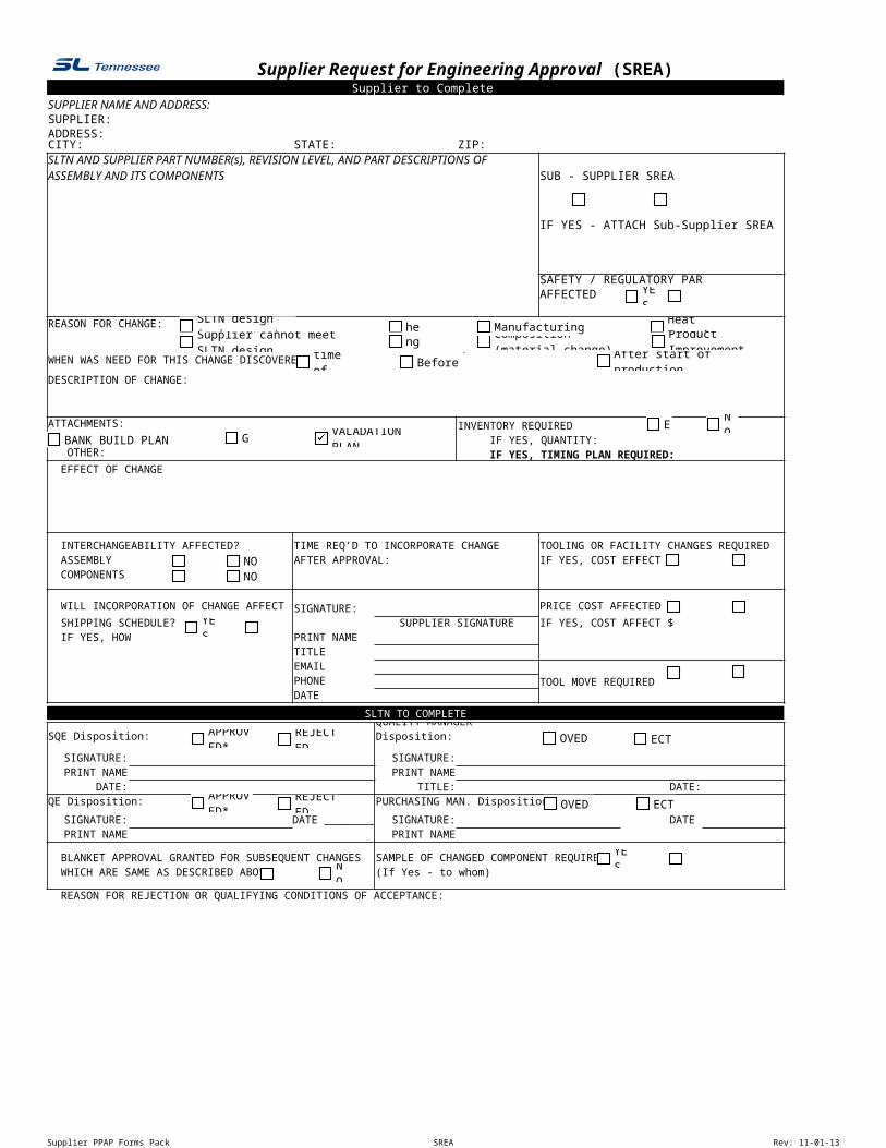
Supplier PPAP Forms Pack SREA Rev: 11-01-13
Supplier to CompleteSUPPLIER NAME AND ADDRESS:SUPPLIER:ADDRESS:CITY: STATE: ZIP:
SUB - SUPPLIER SREA
IF YES - ATTACH Sub-Supplier SREA
SAFETY / REGULATORY PARTAFFECTED
REASON FOR CHANGE:
WHEN WAS NEED FOR THIS CHANGE DISCOVERED?
DESCRIPTION OF CHANGE:
ATTACHMENTS: INVENTORY REQUIRED IF YES, QUANTITY:
OTHER: IF YES, TIMING PLAN REQUIRED: EFFECT OF CHANGE
INTERCHANGEABILITY AFFECTED? TOOLING OR FACILITY CHANGES REQUIRED ASSEMBLY IF YES, COST EFFECT $ COMPONENTS
WILL INCORPORATION OF CHANGE AFFECT SIGNATURE: PRICE COST AFFECTED
SHIPPING SCHEDULE? SUPPLIER SIGNATURE IF YES, COST AFFECT $ IF YES, HOW PRINT NAME
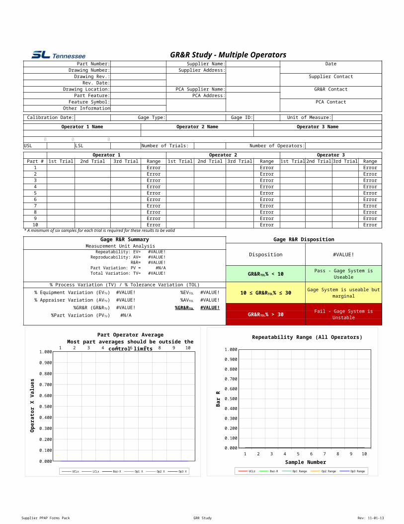
Part Operator AverageMost part averages should be outside the control limits
UCLx LCLx Bar-X Op1 X Op2 X Op3 X
Ope
rato
r X V
alue
s
1 2 3 4 5 6 7 8 9 100.000
0.100
0.200
0.300
0.400
0.500
0.600
0.700
0.800
0.900
1.000
Repeatability Range (All Operators)
UCLr Bar-R Op1 Range Op2 Range Op3 Range
Sample Number
Bar R
E5
Part number as it appears on the SL Part Print.
I5
Full name of supplier
E6
Drawing number listed on balloon drawing.
I6
Enter supplier address
K6
Enter the date(s) the data was compiled
E7
Most recent revision number taken from SL print.
E8
Date revision was completed
K8
Contact representative at Supplier
E9
Grid Location
I9
Process Capability Analysis supplier name
E10
Specific Call Out
I10
Process Capability Analysis Supplier address
K10
Name of individual responsible for GR&R study.
E11
Identification used for the feature
E12
Add additional pertinent information
K12
Name of Process Capabilty Analysis supplier contact person
D14
Date of iInstrumentation's last calibration
G14
Enter type of gage used
J14
ID of Equipment
M14
Unit of measure used
B16
Insert the name of the first operator involved in the GR&R study.
F16
Insert the name of the second operator involved in the GR&R study.
J16
Insert the name of the third operator involved in the GR&R study.
B19
Upper Spec Level
C19
Upper Spec Limit
D19
Lower Spec Limit
F19
Enter the number of trials operators conducted
I19
Total number of operators involved in study
C22
Enter 1st trial data
D22
Enter 2nd trial data
E22
Enter 3rd trial data
F22
Output is range of operator data results
G22
Enter 1st trial data
H22
Enter 2nd trial data
I22
Enter 3rd trial data
J22
Output is range of operator data results
K22
Enter 1st trial data
L22
Enter 2nd trial data
M22
Enter 3rd trial data
N22
Output is range of operator data results
B35
Gage R&R Is the Percentage of Measurement Variation (Repeatability and Reproducibility) in the Process Under 10%: Acceptable Gage 10% to 30%: May Be Acceptable Over 30%: Unacceptable and Should Be Corrected or Replaced
D37
Repeatability (Gage precision) The variation in measurements obtained with one gage when used several times by an operator while measuring the identical characteristic on the same part. Referred to as equipment variation in a Gage R&R study.
D38
Reproducibility (Operator precision) The variation in the average of the measurements made by different operators using the same gage when measuring a characteristic on one part. Referred to as Operator Variation in a Gage R&R Study.
D39
Repeatability and Reproductability
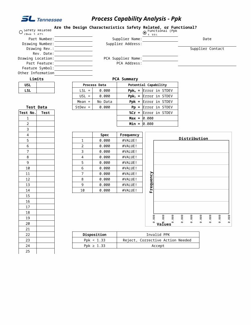
Supplier PPAP Forms Pack Process Cap Analysis -Ppk Rev: 11-01-13
Process Capability Analysis - PpkAre the Design Characteristics Safety Related, or Functional?
Part Number: Supplier Name: DateDrawing Number: Supplier Address:
Use when: (a) You are a new supplier to Cooper that has already been manufacturing the specified part, or (b) you are an existing supplier who has been found to have supplied a large number of nonconforming parts.
Ppku = Ppkl =
0.00
0
0.00
0
0.00
0
0.00
0
0.00
0
0.00
0
0.00
0
0.00
0
0.00
0
Distribution
Values
Freq
uenc
y
Safety Related (Ppk ≥ 1.67)
Functional (Ppk ≥ 1.33)
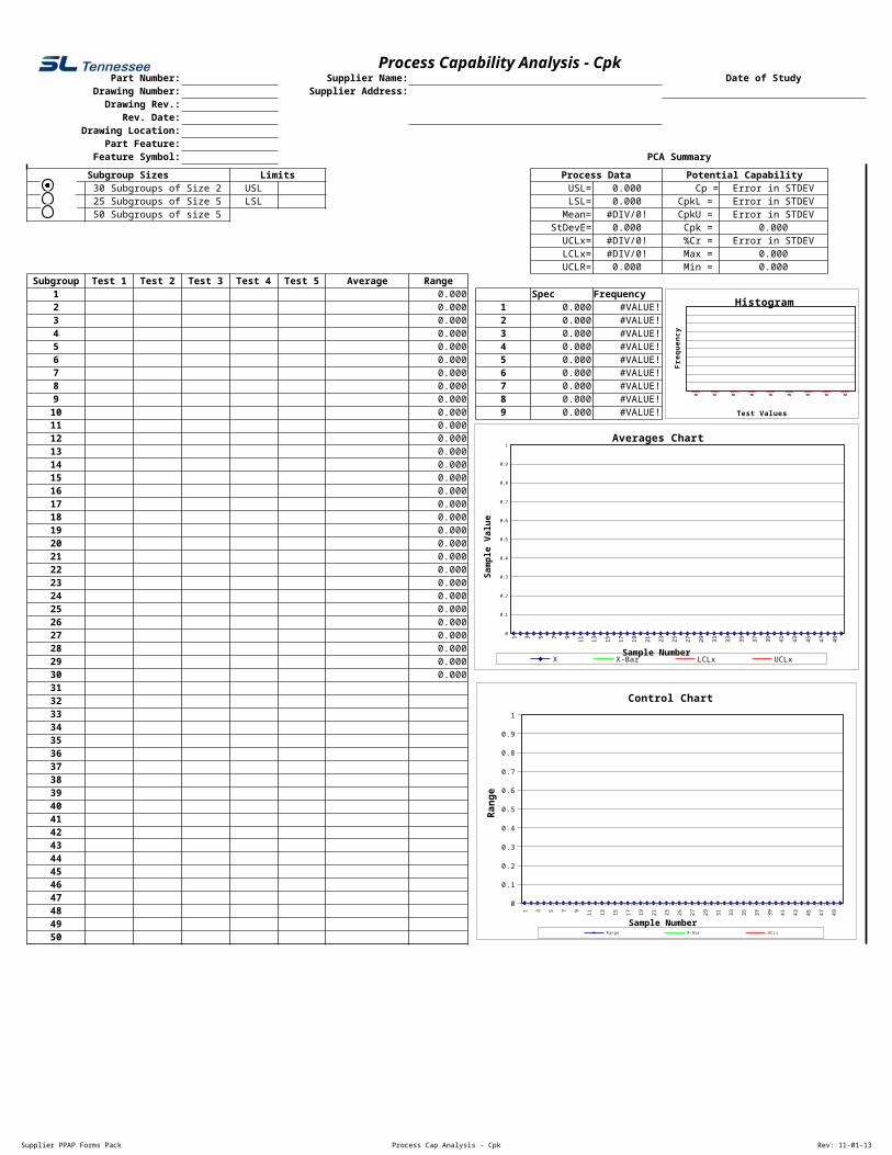
Supplier PPAP Forms Pack Process Cap Analysis - Cpk Rev: 11-01-13
Process Capability Analysis - CpkPart Number: Supplier Name: Date of Study
Drawing Number: Supplier Address:Drawing Rev.:
Rev. Date:Drawing Location:
Part Feature:Feature Symbol: PCA Summary
Subgroup Sizes Limits Process Data Potential Capability1 30 Subgroups of Size 2 USL USL= 0.000 Cp = Error in STDEV
25 Subgroups of Size 5 LSL LSL= 0.000 CpkL = Error in STDEV50 Subgroups of size 5 Mean= #DIV/0! CpkU = Error in STDEV
StDevE= 0.000 Cpk = 0.000UCLx= #DIV/0! %Cr = Error in STDEVLCLx= #DIV/0! Max = 0.000
UCLR= 0.000 Min = 0.000Subgroup Test 1 Test 2 Test 3 Test 4 Test 5 Average Range