0 lfursurfhvvru 0,& 1r whv
TRANSCRIPT
22415 Microprocessor (MIC) Notes
4th Sem MCQ QB (All Subjects) : click here
Notes By Prof. Nikita Chavan cwipedia.in
Topic 2 :16 Bit Microprocessor: 8086 (24 Marks)
Features of 8086
8086 is a 16 bit processor. It’s ALU, internal registers works with 16bit binary word 8086 has a 16bit data bus. It can read or write data to a memory/port either 16bits or 8 bit at a
time 8086 has a 20bit address bus which means, it can address upto 2^20 = 1MB memory
location Frequency range of 8086 is 6-10 MHz
Introduction to 16-bit Microprocessor: The 16-bit Microprocessor families are designed primarily to complete with
microcomputers and are oriented towards high-level languages. Their applications sometimes overlap those of the 8-bit microprocessors. The have powerful instruction sets and capable of addressing mega bytes of memory.
The era of 16-bit Microprocessors began in 1974 with the introduction of PACE chip by National Semiconductor. The Texas Instruments TMS9900 was introduced in the year 1976. The Intel 8086 commercially available in the year 1978, Zilog Z800 in the year 1979, The Motorola MC68000 in the year 1980.
The 16-bit Microprocessors are available in different pin packages.
Ex: Intel 8086/8088 40 pin package
Zilog Z8001 40 pin package
Digital equipment LSI-II 40 pin package
Motorola MC68000 64 pin package
National Semiconductor NS16000 48 pin package
The primary objectives of this 16-bit Microprocessor can be summarized as follows.
1. Increase memory addressing capability
2. Increase execution speed
3. Provide a powerful instruction set
Facilitate programming in high-level languages.
The INTEL iAPX 8086/8088: It is a 16-bit Microprocessor housed in a 40-pin Dual-Inline-Package (DIP) and capable
of addressing 1Megabyte of memory, various versions of this chip can operate with different clock frequencies
i. 8086 (5 MHz) ii.8086-2 (8 MHz) iii. 8086-1 (10 MHz).
It contains approximately 29,000 transistors and is fabricated using the HMOS technology . The term 16-bit means that its arithmetic logic unit, its internal registers and most of its instructions are designed to work with 16-bit binary word. The 8086 Microprocessor has a 16-bit data bus, so it can read from or write data to memory and ports either 16-bits or 8-bits at a time. The 8086 Microprocessor has 20-bit address bus, so it can address any one of 220 or 1,048,576 memory locations. Here 16-bit words will be stored in two consecutive memory locations. If the first byte of a word is at an even address, the 8086 can read entire word in one operation, If the first byte of the word is at an odd address the 8086 will read the first byte with one bus operation and the
second byte with another bus operation
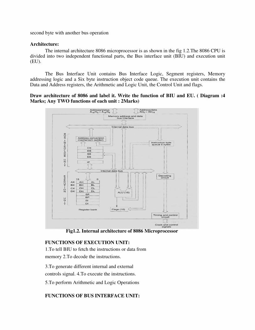
Architecture: The internal architecture 8086 microprocessor is as shown in the fig 1.2.The 8086 CPU is
divided into two independent functional parts, the Bus interface unit (BIU) and execution unit (EU).
The Bus Interface Unit contains Bus Interface Logic, Segment registers, Memory addressing logic and a Six byte instruction object code queue. The execution unit contains the Data and Address registers, the Arithmetic and Logic Unit, the Control Unit and flags. Draw architecture of 8086 and label it. Write the function of BIU and EU. ( Diagram :4 Marks; Any TWO functions of each unit : 2Marks)
Fig1.2. Internal architecture of 8086 Microprocessor
FUNCTIONS OF EXECUTION UNIT: 1.To tell BIU to fetch the instructions or data from
memory 2.To decode the instructions.
3.To generate different internal and external
controls signal. 4.To execute the instructions.
5.To perform Arithmetic and Logic Operations
FUNCTIONS OF BUS INTERFACE UNIT:
1.Communication with External devices and peripheral including memory
via bus. 2.Fetch the instruction or data from memory.
3.Read data from the port.
4.Write the data to memory and port.
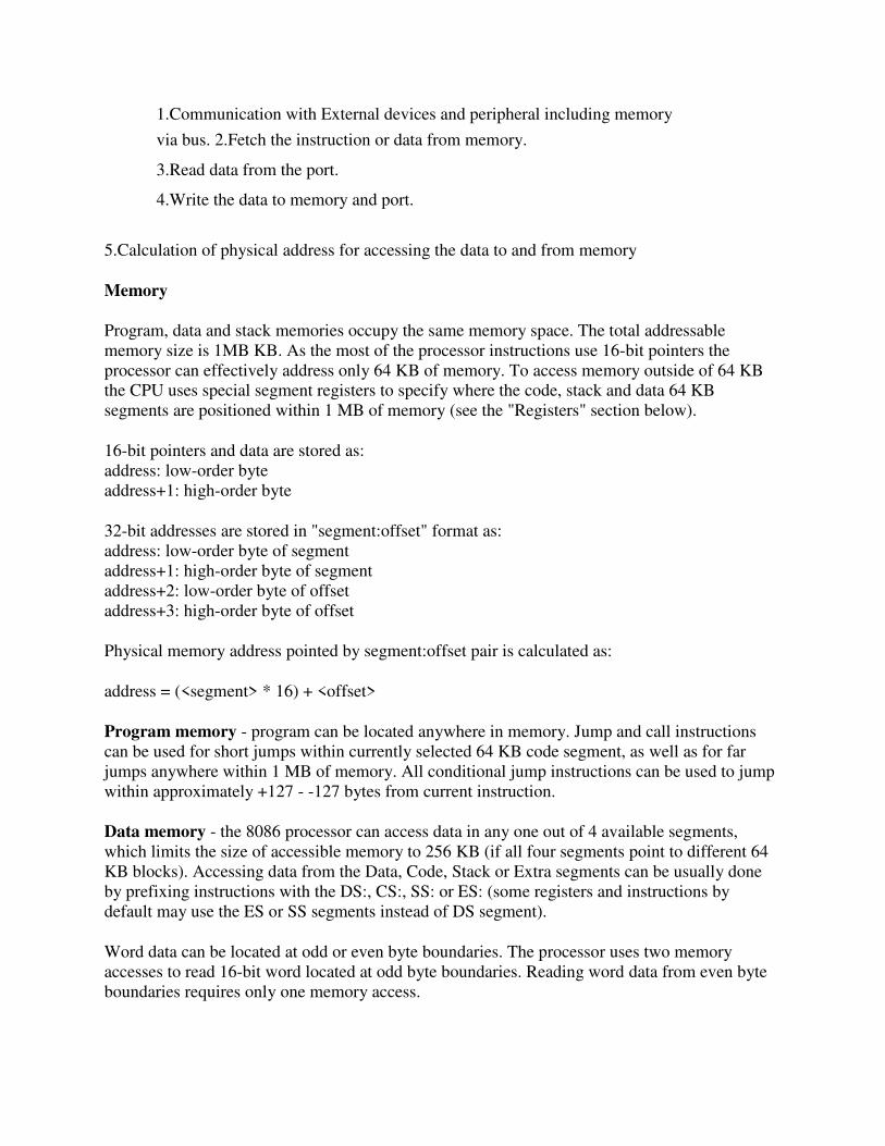
5.Calculation of physical address for accessing the data to and from memory
Memory
Program, data and stack memories occupy the same memory space. The total addressable
memory size is 1MB KB. As the most of the processor instructions use 16-bit pointers the
processor can effectively address only 64 KB of memory. To access memory outside of 64 KB
the CPU uses special segment registers to specify where the code, stack and data 64 KB
segments are positioned within 1 MB of memory (see the "Registers" section below).
16-bit pointers and data are stored as:
address: low-order byte
address+1: high-order byte
32-bit addresses are stored in "segment:offset" format as:
address: low-order byte of segment
address+1: high-order byte of segment
address+2: low-order byte of offset
address+3: high-order byte of offset
Physical memory address pointed by segment:offset pair is calculated as:
address = (<segment> * 16) + <offset>
Program memory - program can be located anywhere in memory. Jump and call instructions
can be used for short jumps within currently selected 64 KB code segment, as well as for far
jumps anywhere within 1 MB of memory. All conditional jump instructions can be used to jump
within approximately +127 - -127 bytes from current instruction.
Data memory - the 8086 processor can access data in any one out of 4 available segments,
which limits the size of accessible memory to 256 KB (if all four segments point to different 64
KB blocks). Accessing data from the Data, Code, Stack or Extra segments can be usually done
by prefixing instructions with the DS:, CS:, SS: or ES: (some registers and instructions by
default may use the ES or SS segments instead of DS segment).
Word data can be located at odd or even byte boundaries. The processor uses two memory
accesses to read 16-bit word located at odd byte boundaries. Reading word data from even byte
boundaries requires only one memory access.
Stack memory can be placed anywhere in memory. The stack can be located at odd memory
addresses, but it is not recommended for performance reasons (see "Data Memory" above).
Reserved locations:
0000h - 03FFh are reserved for interrupt vectors. Each interrupt vector is a 32-bit pointer
in format segment:offset.
FFFF0h - FFFFFh - after RESET the processor always starts program execution at the
FFFF0h address.
Interrupts
The processor has the following interrupts:
INTR is a maskable hardware interrupt. The interrupt can be enabled/disabled using STI/CLI
instructions or using more complicated method of updating the FLAGS register with the help of
the POPF instruction. When an interrupt occurs, the processor stores FLAGS register into stack,
disables further interrupts, fetches from the bus one byte representing interrupt type, and jumps
to interrupt processing routine address of which is stored in location 4 * <interrupt type>.
Interrupt processing routine should return with the IRET instruction.
NMI is a non-maskable interrupt. Interrupt is processed in the same way as the INTR interrupt.
Interrupt type of the NMI is 2, i.e. the address of the NMI processing routine is stored in location
0008h. This interrupt has higher priority then the maskable interrupt.
Software interrupts can be caused by:
INT instruction - breakpoint interrupt. This is a type 3 interrupt.
INT <interrupt number> instruction - any one interrupt from available 256 interrupts.
INTO instruction - interrupt on overflow
Single-step interrupt - generated if the TF flag is set. This is a type 1 interrupt. When the
CPU processes this interrupt it clears TF flag before calling the interrupt processing
routine.
Processor exceptions: divide error (type 0), unused opcode (type 6) and escape opcode
(type 7).
Software interrupt processing is the same as for the hardware interrupts.
I/O ports
65536 8-bit I/O ports. These ports can be also addressed as 32768 16-bit I/O ports.
Registers
Most of the registers contain data/instruction offsets within 64 KB memory segment. There are
four different 64 KB segments for instructions, stack, data and extra data. To specify where in 1
MB of processor memory these 4 segments are located the 8086 microprocessor uses four
segment registers:
Code segment (CS) is a 16-bit register containing address of 64 KB segment with processor
instructions. The processor uses CS segment for all accesses to instructions referenced by
instruction pointer (IP) register. CS register cannot be changed directly. The CS register is
automatically updated during far jump, far call and far return instructions.
Stack segment (SS) is a 16-bit register containing address of 64KB segment with program stack.
By default, the processor assumes that all data referenced by the stack pointer (SP) and base
pointer (BP) registers is located in the stack segment. SS register can be changed directly using
POP instruction.
Data segment (DS) is a 16-bit register containing address of 64KB segment with program data.
By default, the processor assumes that all data referenced by general registers (AX, BX, CX,
DX) and index register (SI, DI) is located in the data segment. DS register can be changed
directly using POP and LDS instructions.
Extra segment (ES) is a 16-bit register containing address of 64KB segment, usually with
program data. By default, the processor assumes that the DI register references the ES segment
in string manipulation instructions. ES register can be changed directly using POP and LES
instructions.
It is possible to change default segments used by general and index registers by prefixing
instructions with a CS, SS, DS or ES prefix.
All general registers of the 8086 microprocessor can be used for arithmetic and logic operations.
The general registers are:
Accumulator register consists of 2 8-bit registers AL and AH, which can be combined together
and used as a 16-bit register AX. AL in this case contains the low-order byte of the word, and
AH contains the high-order byte. Accumulator can be used for I/O operations and string
manipulation.
Base register consists of 2 8-bit registers BL and BH, which can be combined together and used
as a 16-bit register BX. BL in this case contains the low-order byte of the word, and BH contains
the high-order byte. BX register usually contains a data pointer used for based, based indexed or
register indirect addressing.
Count register consists of 2 8-bit registers CL and CH, which can be combined together and
used as a 16-bit register CX. When combined, CL register contains the low-order byte of the
word, and CH contains the high-order byte. Count register can be used as a counter in string
manipulation and shift/rotate instructions.
Data register consists of 2 8-bit registers DL and DH, which can be combined together and used
as a 16-bit register DX. When combined, DL register contains the low-order byte of the word,

and DH contains the high-order byte. Data register can be used as a port number in I/O
operations. In integer 32-bit multiply and divide instruction the DX register contains high-order
word of the initial or resulting number.
The following registers are both general and index registers:
Stack Pointer (SP) is a 16-bit register pointing to program stack.
Base Pointer (BP) is a 16-bit register pointing to data in stack segment. BP register is usually
used for based, based indexed or register indirect addressing.
Source Index (SI) is a 16-bit register. SI is used for indexed, based indexed and register indirect
addressing, as well as a source data address in string manipulation instructions.
Destination Index (DI) is a 16-bit register. DI is used for indexed, based indexed and register
indirect addressing, as well as a destination data address in string manipulation instructions.
Other registers:
Instruction Pointer (IP) is a 16-bit register.
Flags is a 16-bit register containing 9 1-bit flags:
Overflow Flag (OF) - set if the result is too large positive number, or is too small
negative number to fit into destination operand.
Direction Flag (DF) - if set then string manipulation instructions will auto-decrement
index registers. If cleared then the index registers will be auto-incremented.
Interrupt-enable Flag (IF) - setting this bit enables maskable interrupts.
Single-step Flag (TF) - if set then single-step interrupt will occur after the next
instruction.
Sign Flag (SF) - set if the most significant bit of the result is set.
Zero Flag (ZF) - set if the result is zero.
Auxiliary carry Flag (AF) - set if there was a carry from or borrow to bits 0-3 in the AL
register.
Parity Flag (PF) - set if parity (the number of "1" bits) in the low-order byte of the result
is even.
Carry Flag (CF) - set if there was a carry from or borrow to the most significant bit
during last result calculation.
Instruction Set
Instruction set of Intel 8086 processor consists of the following instructions:
Data moving instructions.
Arithmetic - add, subtract, increment, decrement, convert byte/word and compare.
Logic - AND, OR, exclusive OR, shift/rotate and test.

String manipulation - load, store, move, compare and scan for byte/word.
Control transfer - conditional, unconditional, call subroutine and return from subroutine.
Input/Output instructions.
Other - setting/clearing flag bits, stack operations, software interrupts, etc.
Addressing modes
Implied - the data value/data address is implicitly associated with the instruction.
Register - references the data in a register or in a register pair.
Immediate - the data is provided in the instruction.
Direct - the instruction operand specifies the memory address where data is located.
Register indirect - instruction specifies a register containing an address, where data is located.
This addressing mode works with SI, DI, BX and BP registers.
Based - 8-bit or 16-bit instruction operand is added to the contents of a base register (BX or BP),
the resulting value is a pointer to location where data resides.
Indexed - 8-bit or 16-bit instruction operand is added to the contents of an index register (SI or
DI), the resulting value is a pointer to location where data resides.
Based Indexed - the contents of a base register (BX or BP) is added to the contents of an index
register (SI or DI), the resulting value is a pointer to location where data resides.
Based Indexed with displacement - 8-bit or 16-bit instruction operand is added to the contents
of a base register (BX or BP) and index register (SI or DI), the resulting value is a pointer to
location where data resides.
Working The BIU sends out address, fetches the instructions from memory, read data from ports
and memory, and writes the data to ports and memory. In other words the BIU handles all transfers of data and addresses on the buses for the execution unit.
The execution unit (EU) of the 8086 tells the BIU where to fetch instructions or data from, decodes instructions and executes instruction. The EU contains control circuitry which directs internal operations. A decoder in the EU translates instructions fetched from memory into a series of actions which the EU carries out. The EU is has a 16-bit ALU which can add, subtract, AND, OR, XOR, increment, decrement, complement or shift binary numbers. The EU is decoding an instruction or executing an instruction which does not require use of the buses.
The Queue: The BIU fetches up to 6 instruction bytes for the following instructions. The BIU stores these prefetched bytes in first-in-first-out register set called a queue. When the EU is ready for its next instruction it simply reads the instruction byte(s) for the instruction from the queue in

the BIU. This is much faster than sending out an address to the system memory and waiting for memory to send back the next instruction byte or bytes. Except in the case of JMP and CALL instructions, where the queue must be dumped and then reloaded starting from a new address, this prefetch-and-queue scheme greatly speeds up processing. Fetching the next instruction while the current instruction executes is called pipelining.
Word Read Each of 1 MB memory address of 8086 represents a byte wide location.16-bit words will
be stored in two consecutive memory locations. If first byte of the data is stored at an even address, 8086 can read the entire word in one operation.
For example if the 16 bit data is stored at even address 00520H is 9634H MOV BX, [00520H]
8086 reads the first byte and stores the data in BL and reads the 2nd
byte and stores the data in BH
BL= (00520H) i.e.BL=34H
BH= (00521H) BH=96H If the first byte of the data is stored at an odd address, 8086 needs two operations to read the 16 bit data.
For example if the 16 bit data is stored at even address 00521H is 3897H MOV BX, [00521H]
In first operation, 8086 reads the 16 bit data from the 00520H location and stores the data of 00521H location in register BL and discards the data of 00520H location In 2
nd operation, 8086
reads the 16 bit data from the 00522H location and stores the data of 00522H location in register BH and discards the data of 00523H location.
BL= (00521H) i.e. BL=97H
BH= (00522H) BH=38H
Byte Read:
MOV BH, [Addr] For Even Address:
Ex: MOV BH, [00520H] 8086 reads the first byte from 00520 location and stores the data in BH and reads the 2
nd byte
from the 00521H location and ignores it BH =[ 00520H]
For Odd Address MOV BH, [Addr]
Ex: MOV BH, [00521H] 8086 reads the first byte from 00520H location and ignores it and reads the 2nd byte from the 00521 location and stores the data in BH
BH = [00521H]
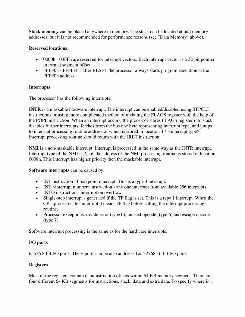
Physical address formation:
The 8086 addresses a segmented memory. The complete physical address which is 20-bits long is generated using segment and offset registers each of the size 16-bit.The content of a segment register also called as segment address, and content of an offset register also called as offset address. To get total physical address, put the lower nibble 0H to segment address and add
offset address. The fig 1.3 shows formation of 20-bit physical address.
Fig. 1.3. Physical address formation
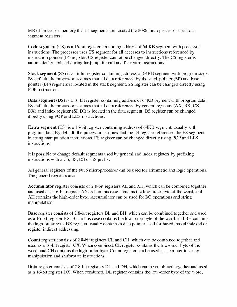
Register organization of 8086:
8086 has a powerful set of registers containing general purpose and special purpose registers. All the registers of 8086 are 16-bit registers. The general purpose registers, can be used either 8-bit registers or 16-bit registers. The general purpose registers are either used for holding the data, variables and intermediate results temporarily or for other purpose like counter or for storing offset address for some particular addressing modes etc. The special purpose registers are used as segment registers, pointers, index registers or as offset storage registers for particular addressing modes. Fig 1.4 shows register organization of 8086. We will categorize the register set into four groups as follows:
General data registers:
AX
SP
AH AL
CS
BP
BX BH BL
SS
CX
FLAGS/PSW
SI
CH CL
DS
DX
DI
DH DL
ES
IP
General data registersSegment registers
Pointers and index registers
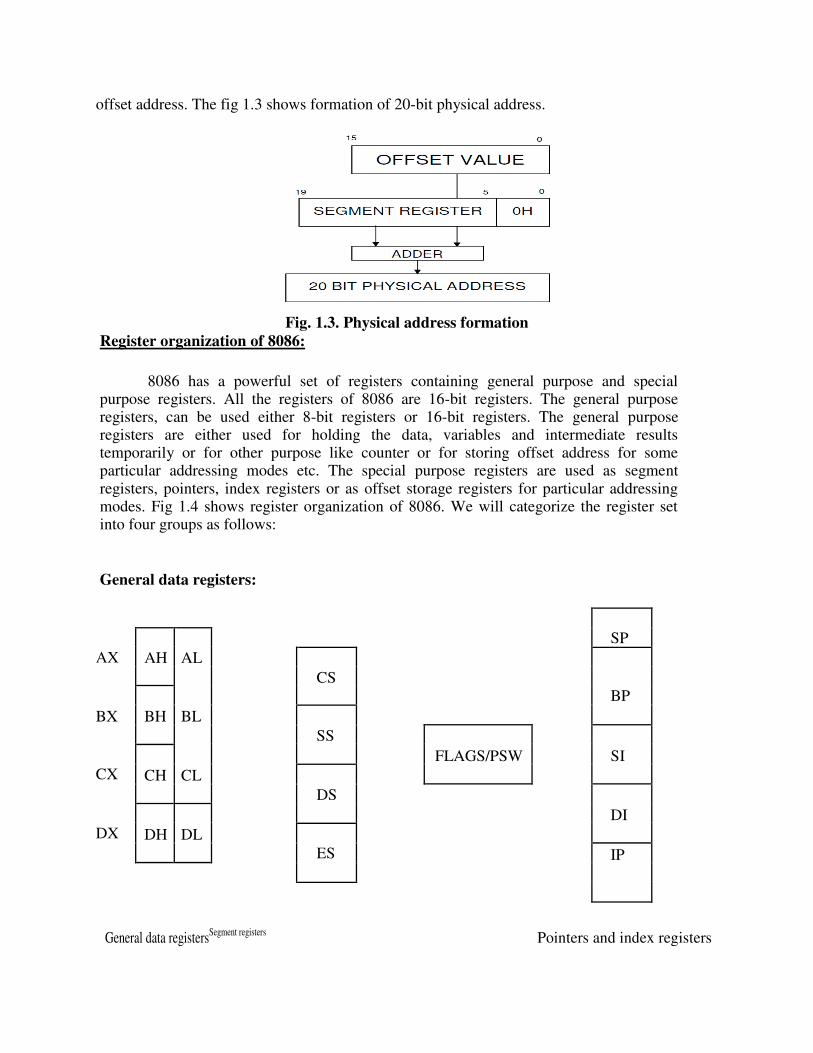
Fig.1.4 Register organization of 8086 Microprocessor
The registers AX, BX, CX, and DX are the general 16-bit registers.
AX Register: Accumulator register consists of two 8-bit registers AL and AH, which can be combined together and used as a 16- bit register AX. AL in this case contains the low-order byte of the word, and AH contains the high-order byte. Accumulator can be used for I/O operations, rotate and string manipulation.
BX Register: This register is mainly used as a base register. It holds the starting base location of a memory region within a data segment. It is used as offset storage for forming physical address in case of certain addressing mode.
CX Register: It is used as default counter or count register in case of string and loop instructions.
DX Register: Data register can be used as a port number in I/O operations and implicit operand or destination in case of few instructions. In integer 32-bit multiply and divide instruction the DX register contains high-order word of the initial or resulting number.
Segment registers: To complete 1Mbyte memory is divided into 16 logical segments. The complete 1Mbyte
memory segmentation is as shown in fig 1.5. Each segment contains 64Kbyte of memory. There are four segment registers.
Code segment (CS) is a 16-bit register containing address of 64 KB segment with processor instructions. The processor uses CS segment for all accesses to instructions referenced by instruction pointer (IP) register. CS register cannot be changed directly. The CS register is automatically updated during far jump, far call and far return instructions. It is used for addressing a memory location in the code segment of the memory, where the executable program is stored.
Stack segment (SS) is a 16-bit register containing address of 64KB segment with program stack. By default, the processor assumes that all data referenced by the stack pointer (SP) and base pointer (BP) registers is located in the stack segment. SS register can be changed directly using POP instruction. It is used for addressing stack segment of memory. The stack segment is that segment of memory, which is used to store stack data.
Data segment (DS) is a 16-bit register containing address of 64KB segment with program data. By default, the processor assumes that all data referenced by general registers (AX, BX, CX, DX) and index register (SI, DI) is located in the data segment. DS register can be changed directly using POP and LDS instructions. It points to the data segment memory where the data is resided.
Extra segment (ES) is a 16-bit register containing address of 64KB segment, usually with
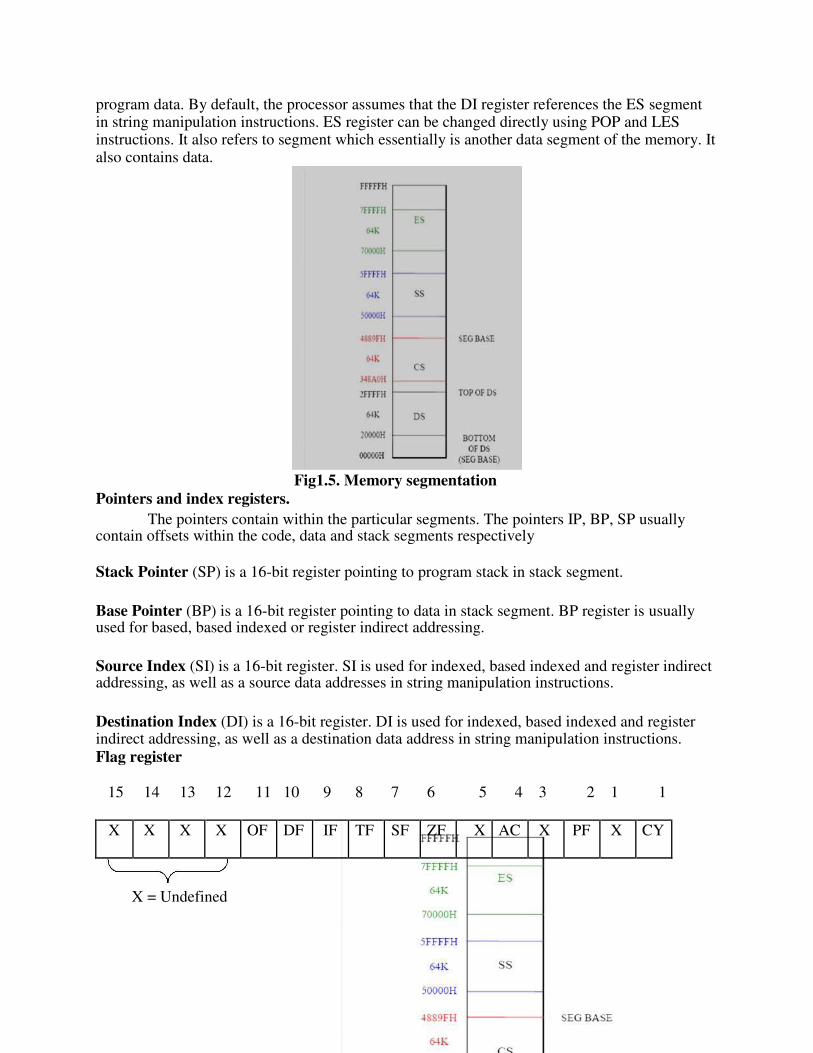
program data. By default, the processor assumes that the DI register references the ES segment in string manipulation instructions. ES register can be changed directly using POP and LES instructions. It also refers to segment which essentially is another data segment of the memory. It also contains data.
Fig1.5. Memory segmentation
Pointers and index registers. The pointers contain within the particular segments. The pointers IP, BP, SP usually
contain offsets within the code, data and stack segments respectively
Stack Pointer (SP) is a 16-bit register pointing to program stack in stack segment.
Base Pointer (BP) is a 16-bit register pointing to data in stack segment. BP register is usually used for based, based indexed or register indirect addressing.
Source Index (SI) is a 16-bit register. SI is used for indexed, based indexed and register indirect addressing, as well as a source data addresses in string manipulation instructions.
Destination Index (DI) is a 16-bit register. DI is used for indexed, based indexed and register indirect addressing, as well as a destination data address in string manipulation instructions.
Flag register
15 14 13 12 11 10 9 8 7 6 5 4 3 2 1 1
X X X X OF DF IF TF SF ZF X AC X PF X CY
X = Undefined
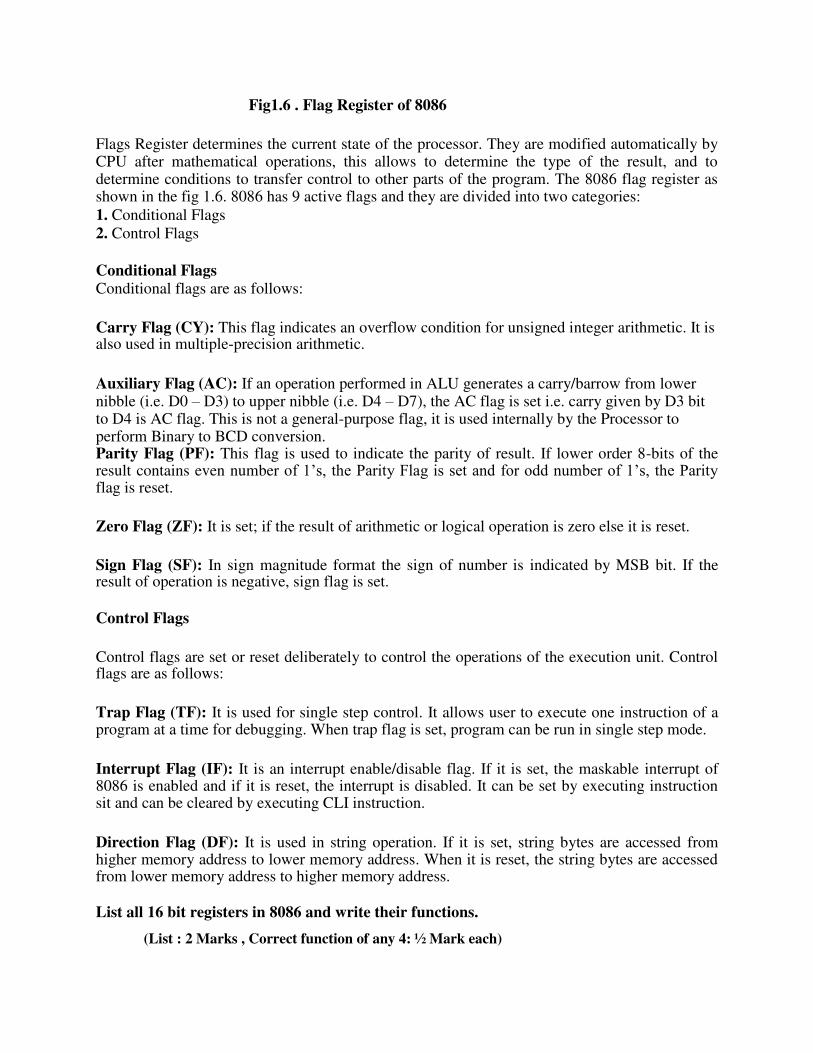
Fig1.6 . Flag Register of 8086
Flags Register determines the current state of the processor. They are modified automatically by CPU after mathematical operations, this allows to determine the type of the result, and to determine conditions to transfer control to other parts of the program. The 8086 flag register as shown in the fig 1.6. 8086 has 9 active flags and they are divided into two categories: 1. Conditional Flags
2. Control Flags
Conditional Flags Conditional flags are as follows:
Carry Flag (CY): This flag indicates an overflow condition for unsigned integer arithmetic. It is also used in multiple-precision arithmetic.
Auxiliary Flag (AC): If an operation performed in ALU generates a carry/barrow from lower nibble (i.e. D0 – D3) to upper nibble (i.e. D4 – D7), the AC flag is set i.e. carry given by D3 bit to D4 is AC flag. This is not a general-purpose flag, it is used internally by the Processor to perform Binary to BCD conversion. Parity Flag (PF): This flag is used to indicate the parity of result. If lower order 8-bits of the result contains even number of 1’s, the Parity Flag is set and for odd number of 1’s, the Parity flag is reset.
Zero Flag (ZF): It is set; if the result of arithmetic or logical operation is zero else it is reset.
Sign Flag (SF): In sign magnitude format the sign of number is indicated by MSB bit. If the result of operation is negative, sign flag is set.
Control Flags
Control flags are set or reset deliberately to control the operations of the execution unit. Control flags are as follows:
Trap Flag (TF): It is used for single step control. It allows user to execute one instruction of a program at a time for debugging. When trap flag is set, program can be run in single step mode.
Interrupt Flag (IF): It is an interrupt enable/disable flag. If it is set, the maskable interrupt of 8086 is enabled and if it is reset, the interrupt is disabled. It can be set by executing instruction sit and can be cleared by executing CLI instruction.
Direction Flag (DF): It is used in string operation. If it is set, string bytes are accessed from higher memory address to lower memory address. When it is reset, the string bytes are accessed from lower memory address to higher memory address.
List all 16 bit registers in 8086 and write their functions.
(List : 2 Marks , Correct function of any 4: ½ Mark each)
Ans: EU contains 8 general purpose registers : AX, BX, CX, DX, SP, BP, SI, DI, DS, CS, SS, ES,IP and flag register.
AX, BX, CX, DX : used as eight 8-bit registers i.e AL, AH, BL, BH, CL, CH, DL, DH or 16-bit register. AL functions as 8-bit accumulator and AX functions as 16-bit accumulator. CX : used as counter register. BX :used as pointer register. DX :used for I/O addressing.
SP , BP : used as pointer register , SP holds 16-bit offset within stack segment and BP contains offset within the data segment
SI, DI : The register SI is used to store the offset of source data in data segment. The register DI is used to store the offset of destination in data or extra segment.
DS, CS, SS and ES : These are used for Data, Code, Stack and Extra Data ( Strings)
respectively. IP: is used as an instruction pointer which holds the address of the next
instruction to be executed by the microprocessor. Flag register is used to hold the status of arithmetic and logic operations along with
control flags.
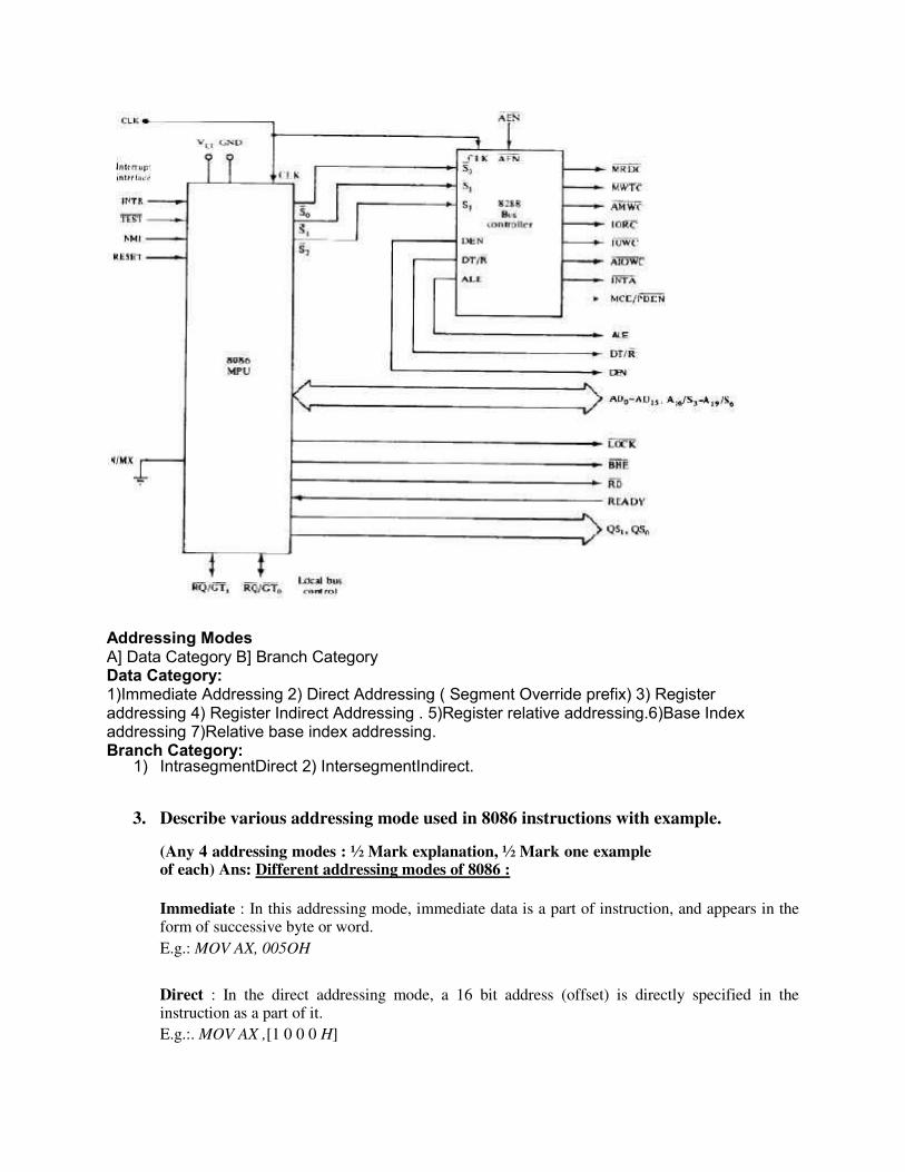
Signal Description of 8086 Microprocessor
The 8086 Microprocessor is a 16-bit CPU available in 3 clock rates, i.e. 5, 8 and 10MHz, packaged in a 40 pin CERDIP or plastic package. The 8086 Microprocessor operates in single processor or multiprocessor configurations to achieve high performance. The pin configuration is as shown in fig1. Some of the pins serve a particular function in minimum mode (single processor mode) and others function in maximum mode (multiprocessor mode) configuration.
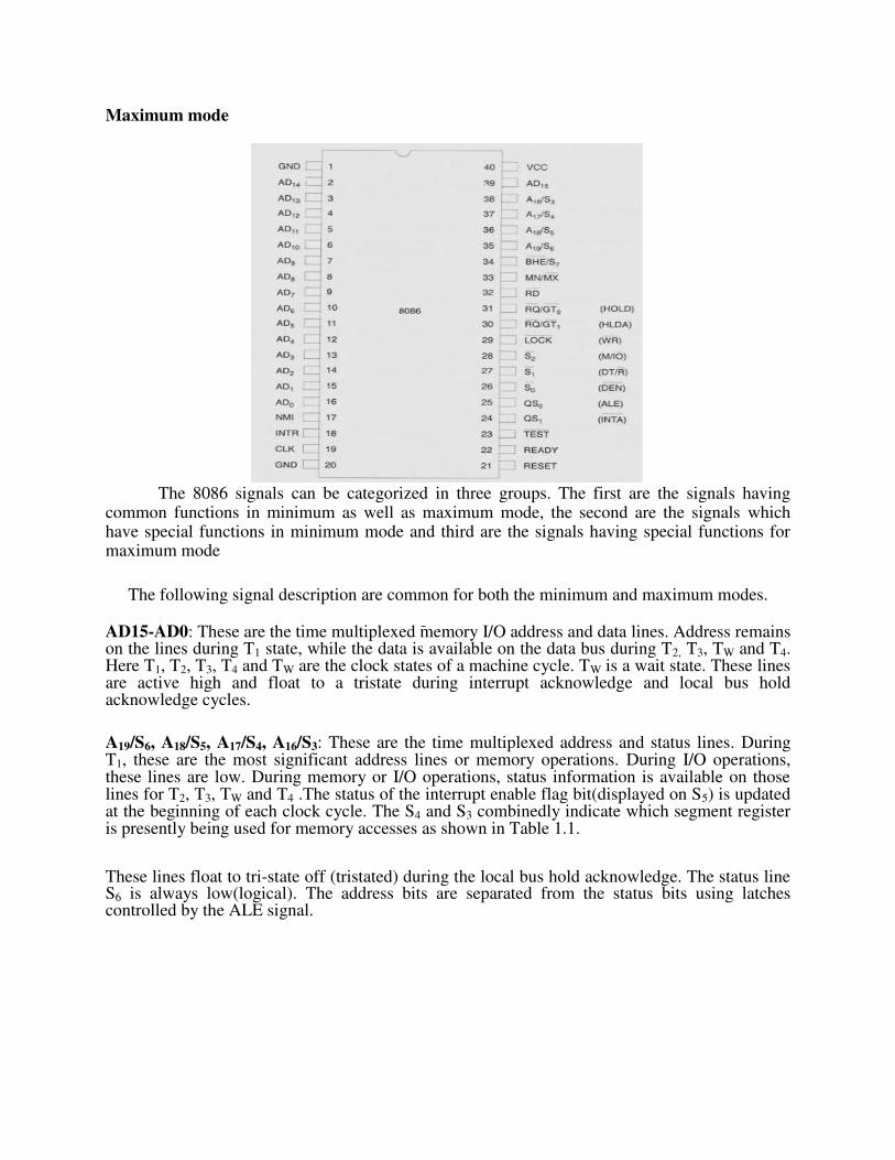
Maximum mode
The 8086 signals can be categorized in three groups. The first are the signals having
common functions in minimum as well as maximum mode, the second are the signals which have special functions in minimum mode and third are the signals having special functions for maximum mode
The following signal description are common for both the minimum and maximum modes.
AD15-AD0: These are the time multiplexed memory I/O address and data lines. Address remains on the lines during T1 state, while the data is available on the data bus during T2, T3, TW and T4. Here T1, T2, T3, T4 and TW are the clock states of a machine cycle. TW is a wait state. These lines are active high and float to a tristate during interrupt acknowledge and local bus hold acknowledge cycles.
A19/S6, A18/S5, A17/S4, A16/S3: These are the time multiplexed address and status lines. During T1, these are the most significant address lines or memory operations. During I/O operations, these lines are low. During memory or I/O operations, status information is available on those lines for T2, T3, TW and T4 .The status of the interrupt enable flag bit(displayed on S5) is updated at the beginning of each clock cycle. The S4 and S3 combinedly indicate which segment register is presently being used for memory accesses as shown in Table 1.1. These lines float to tri-state off (tristated) during the local bus hold acknowledge. The status line S6 is always low(logical). The address bits are separated from the status bits using latches controlled by the ALE signal.

S4 S3 Indication
0 0 Alternate Data
0 1 Stack
1 0 Code or none
1 1 Data
Table 1.1 Bus High Enable/Status BHE/S7-Bus High Enable/Status: The bus high enable signal is used to indicate the transfer of data over the higher order (D15-D8) data bus as shown in Table 1.2. It goes low for the data transfers over D15-D8 and is used to derive chip selects of odd address memory bank or peripherals. BHE is low during T1 for read, write and interrupt acknowledge cycles, when- ever a byte is to be transferred on the higher byte of the data bus. The status information is available during T2, T3 and T4. The signal is active low and is tristated during 'hold'. It is low during T1 for the first pulse of the interrupt acknowledge cycle.
BHE A0 Indication
0 0 Whole Word
0 1 Upper byte from or to odd address
1 0 Upper byte from or to even address
1 1 None RD-Read: Read signal, when low, indicates the peripherals that the processor is performing a memory or I/O read operation. RD is active low and shows the state for T2, T3, TW of any read cycle. The signal remains tristated during the 'hold acknowledge'.
READY: This is the acknowledgement from the slow devices or memory that they have completed the data transfer. The signal made available by the devices is synchronized by the 8284A clock generator to provide ready input to the 8086. The signal is active high.
INTR-lnterrupt Request: This is a level triggered input. This is sampled during the last clock cycle of each instruction to determine the availability of the request. If any interrupt request is pending, the processor enters the interrupt acknowledge cycle. This can be internally masked by resetting the interrupt enable flag. This signal is active high and internally synchronized.
TEST: This input is examined by a 'WAIT' instruction. If the TEST input goes low, execution will continue, else, the processor remains in an idle state. The input is synchronized internally during each clock cycle on leading edge of clock.
NMI-Non-maskable Interrupt: This is an edge-triggered input which causes a Type2 interrrupt. The NMI is not maskable internally by software. A transition from low to high initiates the interrupt response at the end of the current instruction. This input is internally synchronized.
RESET: This input causes the processor to terminate the current activity and start execution from FFFF0H. The signal is active high and must be active for at least four clock cycles. It restarts execution when the RESET returns low. RESET is also internally synchronized.
CLK-Clock Input: The clock input provides the basic timing for processor operation and bus control activity. Its an asymmetric square wave with 33% duty cycle. The range of frequency for different 8086 versions is from 5MHz to 10MHz. VCC : +5V power supply for the operation of the internal circuit. GND ground for the internal circuit.
MN/MX :The logic level at this pin decides whether the processor is to operate in either minimum (single processor) or maximum (multiprocessor) mode. The following pin functions are for the minimum mode operation of 8086. M/IO -Memory/IO: This is a status line logically equivalent to S2 in maximum mode. When it is low, it indicates the CPU is having an I/O operation, and when it is high, it indicates that the CPU is having a memory operation. This line becomes active in the previous T4 and remains active till final T4 of the current cycle. It is tristated during local bus "hold acknowledge”.
INTA -Interrupt Acknowledge: This signal is used as a read strobe for interrupt acknowledge cycles. In other words, when it goes low, it means that the processor has accepted the interrupt. It is active low during T2, T3 and TW of each interrupt acknowledge cycle.
ALE-Address latch Enable: This output signal indicates the availability of the valid address on the address/data lines, and is connected to latch enable input of latches. This signal is active high and is never tristated.
DT /R -Data Transmit/Receive: This output is used to decide the direction of data flow through the transreceivers (bidirectional buffers). When the processor sends out data, this signal is high and when the processor is receiving data, this signal is low. Logically, this is equivalent to S1 in maximum mode. Its timing is the same as M/I/O. This is tristated during 'hold acknowledge'.
DEN-Data Enable This signal indicates the availability of valid data over the address/data lines. It is used to enable the transreceivers (bidirectional buffers) to separate the data from the multiplexed address/data signal. It is active from the middle ofT2 until the middle of T4 DEN is tristated during 'hold acknowledge' cycle.
HOLD, HLDA-Hold/Hold Acknowledge: When the HOLD line goes high, it indicates to the processor that another master is requesting the bus access. The processor, after receiving the HOLD request, issues the hold acknowledge signal on HLDA pin, in the middle of the next clock cycle after completing the current bus (instruction) cycle. At the same time, the processor floats the local bus and control lines. When the processor detects the HOLD line low, it lowers the
HLDA signal. HOLD is an asynchronous input, and it should be externally synchronized.
If the DMA request is made while the CPU is performing a memory or I/O cycle, it will release the local bus during T 4 provided: 1. The request occurs on or before T 2 state of the current cycle.
2. The current cycle is not operating over the lower byte of a word (or operating on an odd address). 3. The current cycle is not the first acknowledge of an interrupt acknowledge sequence. 4. A Lock instruction is not being executed. So far we have presented the pin descriptions of 8086 in minimum mode.
The following pin functions are applicable for maximum mode operation of 8086.
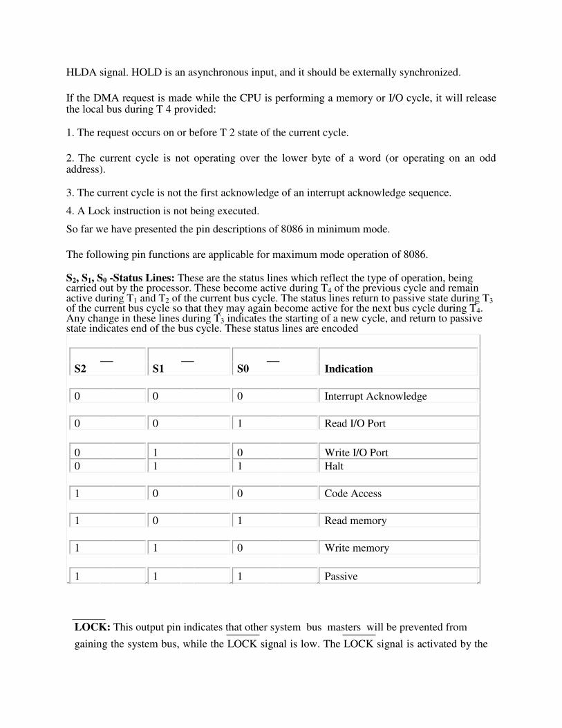
S2, S1, S0 -Status Lines: These are the status lines which reflect the type of operation, being carried out by the processor. These become active during T4 of the previous cycle and remain active during T1 and T2 of the current bus cycle. The status lines return to passive state during T3 of the current bus cycle so that they may again become active for the next bus cycle during T4. Any change in these lines during T3 indicates the starting of a new cycle, and return to passive state indicates end of the bus cycle. These status lines are encoded
S2 S1 S0 Indication
0 0 0 Interrupt Acknowledge
0 0 1 Read I/O Port
0 1 0 Write I/O Port
0 1 1 Halt
1 0 0 Code Access
1 0 1 Read memory
1 1 0 Write memory
1 1 1 Passive
LOCK: This output pin indicates that other system bus masters will be prevented from
gaining the system bus, while the LOCK signal is low. The LOCK signal is activated by the

'LOCK' prefix instruction and remains active until the completion of the next instruction. This floats to tri-state off during "hold acknowledge". When the CPU is executing a critical instruction which requires the system bus, the LOCK prefix instruction ensures that other processors connected in the system will not gain the control of the bus. The 8086, while executing the prefixed instruction, asserts the bus lock signal output, which may be connected to an external bus controller.
QS1, QS0-Queue Status: These lines give information about the status of the code-prefetch queue. These are active during the CLK cycle after which the queue operation is performed. These are encoded as shown in Table 1.4.
QS1, QS0 Indication
0 0 No operation
0 1 First byte of opcode from the queue
1 0 Empty queue
1 1 Subsequent byte from the queue RQ/GT0, RQ/GT1-ReQuest/Grant: These pins are used by other local bus masters, in maximum mode, to force the processor to release the local bus at the end of the processor's current bus cycle. Each of the pins is bidirectional with RQ/GT0 having higher priority than RQ/ GT1, RQ/GT pins have internal pull-up resistors and may be left unconnected. The request! grant sequence is as follows:
1. A pulse one clock wide from another bus master requests the bus access to 8086. 2. During T4 (current) or T1 (next) clock cycle, a pulse one clock wide from 8086 to the
requesting master, indicates that the 8086 has allowed the local bus to float and that it will enter the "hold acknowledge" state at next clock cycle. The CPU's bus interface unit is likely to be disconnected from the local bus of the system
3. A one clock wide pulse from the another master indicates to 8086 that the 'hold' request is about to end and the 8086 may regain control of the local bus at the next clock cycle. Thus each master to master exchange of the local bus is a sequence of 3 pulses. There must be at least one dead clock cycle after each bus exchange. The request and grant pulses are active low. For the bus requests those are received while 8086 is performing memory or I/O cycle, the granting of the bus is governed by the rules as discussed i~ case of HOLD, and HLDA in minimum mode.
State the function of the following pins of 8086 (i) NMI
(ii) TEST
(iii) DEN
(iv)MN/MX
(Correct one function : 1 Mark each) (i) NMI An edge triggered signal on this pin causes 8086 to interrupt the program it is executing and execute
Interrupt service Procedure corresponding to Type-2 interrupt.

NMI is Non-maskable by software. ii)TEST – Used to test the status of math co-processor 8087. If signal goes low, execution will continue, else processor remains in an idle state. iii)DEN This is active low signal, to indicate availability of valid data over AD0-AD15.
Used to enable transreceivers(bi-directional buffers) 8286 or 74LS245 to separate data from multiplexed address/data signal . iv)MN/MX This signal indicates operating mode of 8086, minimum or maximum.
When this pin connected to
1) Vcc, the processor operates in minimum mode, 2) Ground , processor operates in maximum mode. 8086-Minimum mode of operation
Minimum Mode Interface Address/Data bus: 20 bits vs 8 bits multiplexed Status signals: A16-A19 multiplexed with status signals S3-S6 respectively.S3 and S4 together form a 2 bit binary code that identifies which of the internal segment registers was used to generate the physical address that was output on the address bus during the current bus cycle. S5 is the logic level of the internal interrupt enable flag, S6 is always logic 0. Control Signals: Address Latch Enable (ALE) is a pulse to logic 1 that signals external circuitry when a valid address is on the bus. This address can be latched in external circuitry on the 1-to-0 edge of the pulse at ALE. IO/M line: memory or I/O transfer is selected (complement for 8086) DT/R line: direction of data is selected SSO (System Status Output) line: =1 when data is read from memory and =0 when code is read from memory (only for 8088) BHE (Bank High Enable) line : =0 for most significant byte of data for 8086 and also carries S7 RD line: =0 when a read cycle is in progress
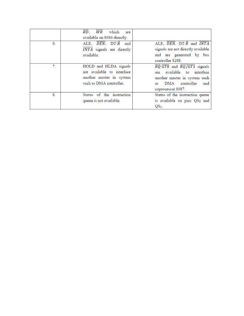
WR line: =0 when a write cyle is in progress DEN line: (Data enable) Enables the external devices to supply data to the processor. Ready line: can be used to insert wait states into the bus cycle so that it is extended by a number of clock periods Interrupt signals: INTR (Interrupt request) :=1 shows there is a service request, sampled at the final clock cycle of each instruction acquisition cycle. INTA : Processor responds with two pulses going to 0 when it services the interrupt and waits for the interrupt service number after the second pulse. TEST: Processor suspends operation when =1. Resumes operation when=0. Used to syncronize the processor to external events. NMI (Nonmaskable interrupt) : A leading edge transition causes the processor go to the interrupt routine after the current instruction is executed. RESET : =0 Starts the reset sequence. Maximum Mode Interface • For multiprocessor environment • 8288 Bus Controller is used for bus control • WR¯,IO/M¯,DT/R¯,DEN¯,ALE, INTA¯ signals are not available. o MRDC¯ (memory read command) o MWRT¯ (memory write command) o AMWC¯ (advanced memory write command) o IORC¯ (I/O read command) o IOWC¯ (I/O write command) o AIOWC¯ (Advanced I/O write command) o INTA¯ (interrupt acknowledge)
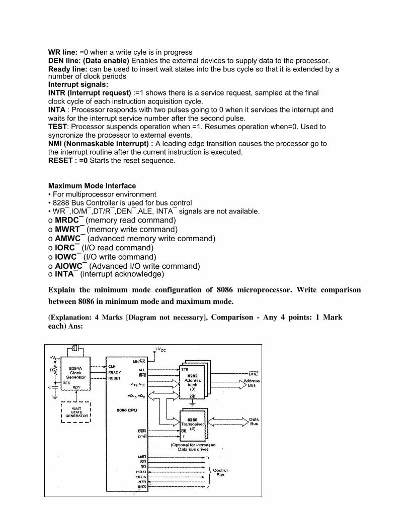
Explain the minimum mode configuration of 8086 microprocessor. Write comparison
between 8086 in minimum mode and maximum mode. (Explanation: 4 Marks [Diagram not necessary], Comparison - Any 4 points: 1 Mark each) Ans:
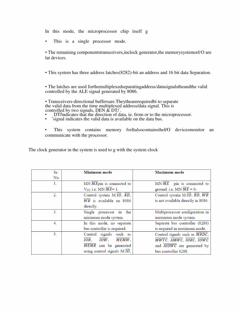
In this mode, the microprocessor chip itself g
• This is a single processor mode.
• The remaining componentstransceivers,inclock generator,the memorysystemorI/O are lat devices.
• This system has three address latches(8282)-bit an address and 16 bit data Separation.
• The latches are used forthemultiplexedseparatingaddress/datasignalstheandthe valid controlled by the ALE signal generated by 8086.
• Transceivers-directional buffersare.Theythearerequiredbi to separate the valid data from the time multiplexed address/data signal. This is controlled by two signals, DEN & DT/ . • DT/ indicates that the direction of data, ie. from or to the microprocessor. • signal indicates the valid data is available on the data bus.
• This system contains memory forItalsocontainstheI/O devicesmonitor an
communicate with the processor. The clock generator in the system is used to g with the system clock
Addressing Modes A] Data Category B] Branch Category Data Category: 1)Immediate Addressing 2) Direct Addressing ( Segment Override prefix) 3) Register addressing 4) Register Indirect Addressing . 5)Register relative addressing.6)Base Index addressing 7)Relative base index addressing. Branch Category:
1) IntrasegmentDirect 2) IntersegmentIndirect.
3. Describe various addressing mode used in 8086 instructions with example.
(Any 4 addressing modes : ½ Mark explanation, ½ Mark one example of each) Ans: Different addressing modes of 8086 :
Immediate : In this addressing mode, immediate data is a part of instruction, and appears in the form of successive byte or word. E.g.: MOV AX, 005OH
Direct : In the direct addressing mode, a 16 bit address (offset) is directly specified in the instruction as a part of it. E.g.:. MOV AX ,[1 0 0 0 H]
Register : In register addressing mode, the data is stored in a register and it is referred using
the
particular register. All the registers except IP may be used in this mode. E.g.:. 1)MOV AX,BX 2)ROR AL,CL 3) AND AL,BL
4. Register Indirect: In this addressing mode, the address of the memory location which contains
data or operand is determined in an indirect way using offset registers. The offset address of data
is in either BX or SI or DI register. The default segment register is either DS or ES.
e.g. MOV AX, BX
5. Indexed : In this addressing mode offset of the operand is stored in one of the index register. DS and ES are the default segments for index registers SI and DI respectively
e.g. MOV AX, SI
6. Register Relative : In this addressing mode, the data is available at an effective address
formed by adding an 8-bit or 16-bit displacement with the content of any one of the registers BX,
BP, SI and DI in the default either DS or ES segment.
e.g. MOV AX, 50H BX
7. Based Indexed: In this addressing mode, the effective address of the data is formed by adding
the content of a base register (any one of BX or BP) to the content of an index register (any one of
SI or DI). The default segment register may be ES or DS.
e.g MOV AX, BX SI 8. Relative Based Indexed : The effective address is formed by adding an 8-bit or 16-bit
displacement with the sum of contents of any one of the base register (BX or BP) and any one of
the index registers in a default segment.
e.g. MOV AX, 50H BX SI
9. Implied addressing mode:
No address is required because the address or the operand is implied in the instruction itself. E.g NOP,STC,CLI,CLD,STD
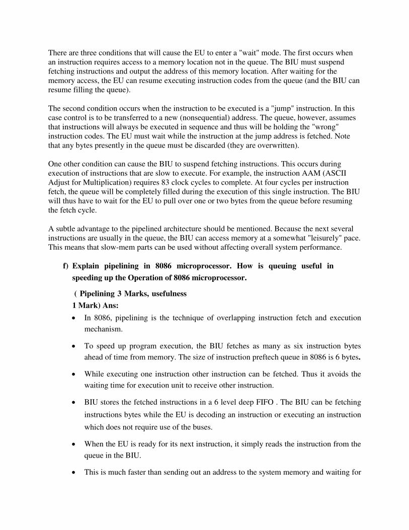
Concept of pipelining
A technique used in advanced microprocessors where the microprocessor begins executing a
second instruction before the first has been completed. That is, several instructions are in the
pipeline simultaneously, each at a different processing stage.
The pipeline is divided into segments and each segment can execute its operation concurrently
with the other segments. When a segment completes an operation, it passes the result to the next
segment in the pipeline and fetches the next operation from the preceding segment. The final
results of each instruction emerge at the end of the pipeline in rapid succession.
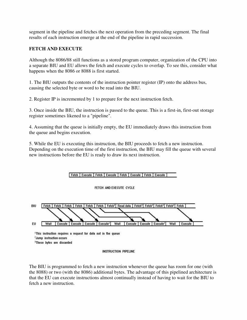
FETCH AND EXECUTE
Although the 8086/88 still functions as a stored program computer, organization of the CPU into
a separate BIU and EU allows the fetch and execute cycles to overlap. To see this, consider what
happens when the 8086 or 8088 is first started.
1. The BIU outputs the contents of the instruction pointer register (IP) onto the address bus,
causing the selected byte or word to be read into the BIU.
2. Register IP is incremented by 1 to prepare for the next instruction fetch.
3. Once inside the BIU, the instruction is passed to the queue. This is a first-in, first-out storage
register sometimes likened to a "pipeline".
4. Assuming that the queue is initially empty, the EU immediately draws this instruction from
the queue and begins execution.
5. While the EU is executing this instruction, the BIU proceeds to fetch a new instruction.
Depending on the execution time of the first instruction, the BIU may fill the queue with several
new instructions before the EU is ready to draw its next instruction.
The BIU is programmed to fetch a new instruction whenever the queue has room for one (with
the 8088) or two (with the 8086) additional bytes. The advantage of this pipelined architecture is
that the EU can execute instructions almost continually instead of having to wait for the BIU to
fetch a new instruction.
There are three conditions that will cause the EU to enter a "wait" mode. The first occurs when
an instruction requires access to a memory location not in the queue. The BIU must suspend
fetching instructions and output the address of this memory location. After waiting for the
memory access, the EU can resume executing instruction codes from the queue (and the BIU can
resume filling the queue).
The second condition occurs when the instruction to be executed is a "jump" instruction. In this
case control is to be transferred to a new (nonsequential) address. The queue, however, assumes
that instructions will always be executed in sequence and thus will be holding the "wrong"
instruction codes. The EU must wait while the instruction at the jump address is fetched. Note
that any bytes presently in the queue must be discarded (they are overwritten).
One other condition can cause the BIU to suspend fetching instructions. This occurs during
execution of instructions that are slow to execute. For example, the instruction AAM (ASCII
Adjust for Multiplication) requires 83 clock cycles to complete. At four cycles per instruction
fetch, the queue will be completely filled during the execution of this single instruction. The BIU
will thus have to wait for the EU to pull over one or two bytes from the queue before resuming
the fetch cycle.
A subtle advantage to the pipelined architecture should be mentioned. Because the next several
instructions are usually in the queue, the BIU can access memory at a somewhat "leisurely" pace.
This means that slow-mem parts can be used without affecting overall system performance.
f) Explain pipelining in 8086 microprocessor. How is queuing useful in
speeding up the Operation of 8086 microprocessor.
( Pipelining 3 Marks, usefulness
1 Mark) Ans:
In 8086, pipelining is the technique of overlapping instruction fetch and execution
mechanism.
To speed up program execution, the BIU fetches as many as six instruction bytes
ahead of time from memory. The size of instruction preftech queue in 8086 is 6 bytes.
While executing one instruction other instruction can be fetched. Thus it avoids the
waiting time for execution unit to receive other instruction.
BIU stores the fetched instructions in a 6 level deep FIFO . The BIU can be fetching
instructions bytes while the EU is decoding an instruction or executing an instruction
which does not require use of the buses.
When the EU is ready for its next instruction, it simply reads the instruction from the
queue in the BIU.
This is much faster than sending out an address to the system memory and waiting for
memory to send back the next instruction byte or bytes.
This improves overall speed of the processor.
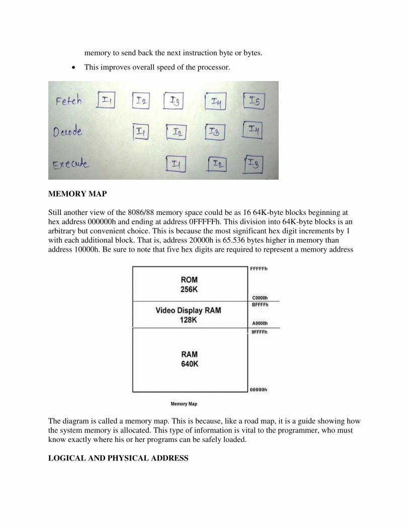
MEMORY MAP
Still another view of the 8086/88 memory space could be as 16 64K-byte blocks beginning at
hex address 000000h and ending at address 0FFFFFh. This division into 64K-byte blocks is an
arbitrary but convenient choice. This is because the most significant hex digit increments by 1
with each additional block. That is, address 20000h is 65.536 bytes higher in memory than
address 10000h. Be sure to note that five hex digits are required to represent a memory address
The diagram is called a memory map. This is because, like a road map, it is a guide showing how
the system memory is allocated. This type of information is vital to the programmer, who must
know exactly where his or her programs can be safely loaded.
LOGICAL AND PHYSICAL ADDRESS
Addresses within a segment can range from address 00000h to address 0FFFFh. This
corresponds to the 64K-byte length of the segment. An address within a segment is called an
offset or logical address. A logical address gives the displacement from the address base of the
segment to the desired location within it, as opposed to its "real" address, which maps directly
anywhere into the 1 MB memory space. This "real" address is called the physical address.
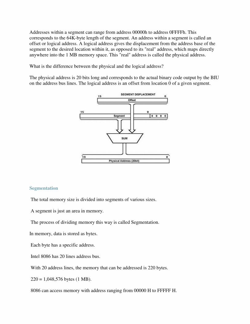
What is the difference between the physical and the logical address?
The physical address is 20 bits long and corresponds to the actual binary code output by the BIU
on the address bus lines. The logical address is an offset from location 0 of a given segment.
Segmentation.
The total memory size is divided into segments of various sizes.
A segment is just an area in memory.
The process of dividing memory this way is called Segmentation.
In memory, data is stored as bytes.
Each byte has a specific address.
Intel 8086 has 20 lines address bus.
With 20 address lines, the memory that can be addressed is 220 bytes.
220 = 1,048,576 bytes (1 MB).
8086 can access memory with address ranging from 00000 H to FFFFF H.

In 8086, memory has four different types of segments.
Code Segment
Data Segment
Stack Segment
Extra Segment
Segment Registers
Each of these segments are addressed by an address stored in corresponding segment register.
These registers are 16-bit in size.
Each register stores the base address (starting address) of the corresponding segment.
Because the segment registers cannot store 20 bits, they only store the upper 16 bits.
How is a 20-bit address obtained if there are only 16- bit registers?
The answer lies in the next few slides.
The 20-bit address of a byte is called its Physical Address.
But, it is specified as a Logical Address.
Logical address is in the form of: Base Address : Offset
Offset is the displacement of the memory location from the starting location of the segment.
Example
The value of Data Segment Register (DS) is 2222 H.
To convert this 16-bit address into 20-bit, the BIU appends 0H to the LSBs of the address.
After appending, the starting address of the Data Segment becomes 22220H.
If the data at any location has a logical address specified as: 2222 H : 0016 H
Then, the number 0016 H is the offset.
2222 H is the value of DS.
To calculate the effective address of the memory, BIU uses the following formula:
Effective Address = Starting Address of Segment + Offset
To find the starting address of the segment, BIU appends the contents of Segment Register with
0H.
Then, it adds offset to it.
Therefore:
EA = 22220 H
+ 0016 H
22236 H
Max. Size of Segment
All offsets are limited to 16-bits.
It means that the maximum size possible for segment is 2^16= 65,535 bytes (64 KB).
The offset of the first location within the segment is 0000 H.
The offset of the last location in the segment is FFFF H.
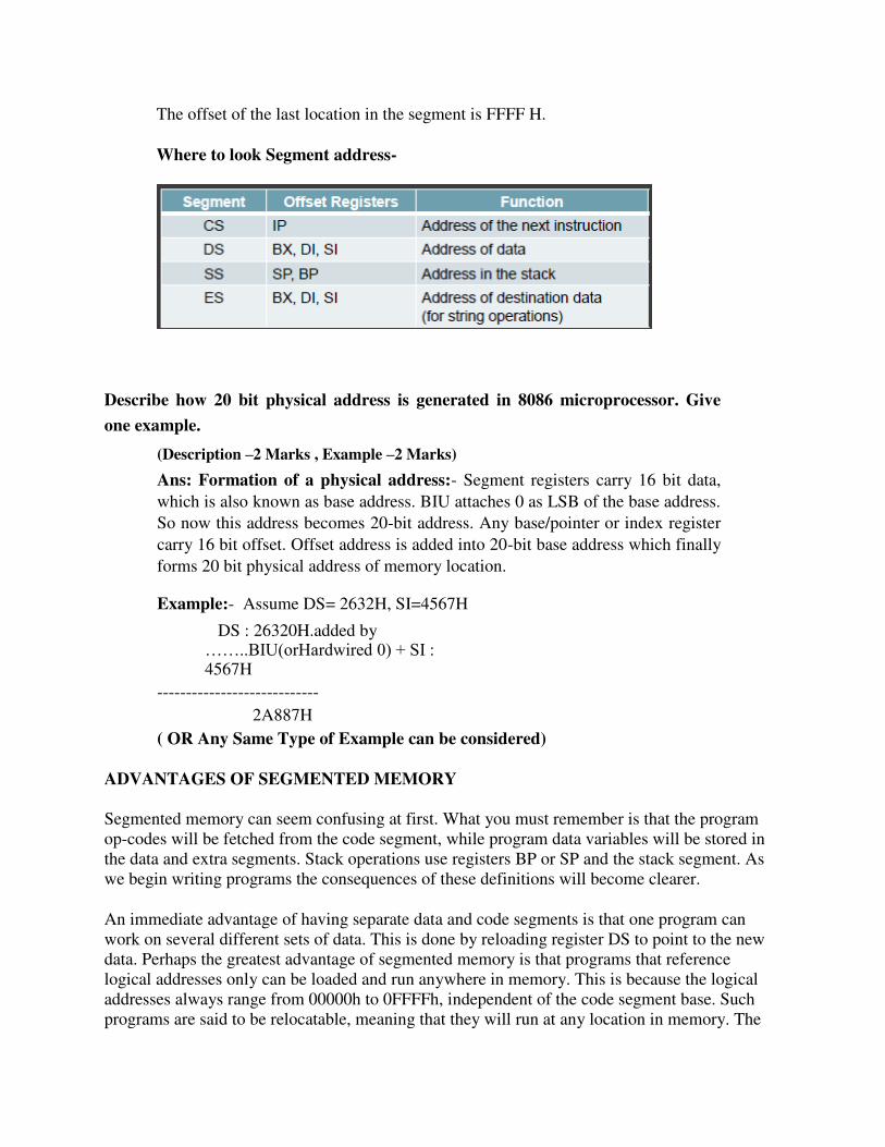
Where to look Segment address-
Describe how 20 bit physical address is generated in 8086 microprocessor. Give
one example.
(Description –2 Marks , Example –2 Marks)
Ans: Formation of a physical address:- Segment registers carry 16 bit data,
which is also known as base address. BIU attaches 0 as LSB of the base address.
So now this address becomes 20-bit address. Any base/pointer or index register
carry 16 bit offset. Offset address is added into 20-bit base address which finally
forms 20 bit physical address of memory location.
Example:- Assume DS= 2632H, SI=4567H
DS : 26320H.added by ……..BIU(orHardwired 0) + SI : 4567H
---------------------------- 2A887H
( OR Any Same Type of Example can be considered)
ADVANTAGES OF SEGMENTED MEMORY
Segmented memory can seem confusing at first. What you must remember is that the program
op-codes will be fetched from the code segment, while program data variables will be stored in
the data and extra segments. Stack operations use registers BP or SP and the stack segment. As
we begin writing programs the consequences of these definitions will become clearer.
An immediate advantage of having separate data and code segments is that one program can
work on several different sets of data. This is done by reloading register DS to point to the new
data. Perhaps the greatest advantage of segmented memory is that programs that reference
logical addresses only can be loaded and run anywhere in memory. This is because the logical
addresses always range from 00000h to 0FFFFh, independent of the code segment base. Such
programs are said to be relocatable, meaning that they will run at any location in memory. The

requirements for writing relocatable programs are that no references be made to physical
addresses, and no changes to the segment registers are allowed.
Describe memory segmentation in 8086 microprocessor and list it‟s four advantages.
Ans : (Description: 2 Marks, Any 4 Advantages : ½ Mark each)
Memory Segmentation: The memory in 8086 based system is organized as
segmented memory. 8086 can access 1Mbyte memory which is divided into
number of logical segments. Each segment is 64KB in size and addressed by
one of the segment register. The 4 segment register in BIU hold the 16-bit
starting address of 4 segments. CS holds program instruction code. Stack
segment stores interrupt & subroutine address. Data segment stores data for
program. Extra segment is used for string data.
Advantages of segmentation
1) With the use of segmentation the instruction and data is never overlapped.
2) The major advantage of segmentation is Dynamic relocatability of program which means
that a program can easily be transferred from one code memory segment to another code
memory segment without changing the effective address.
3) Segmentation can be used in multi-user time shared system. 4) Segmentation allows two processes to share data.
5) Segmentation allows you to extend the addressability of a processor i.e., address up to
1MB although the actual addresses to be handled are of 16 bit size. 6) Programs and data can be stored separately from each other in segmentation.
AN INTRODUCTION TO INTERRUPTS INTERRUPTS There are two main types of interrupt in the 8086 microprocessor, internal and external hardware interrupts. Hardware interrupts occur when a peripheral device asserts an interrupt input pin of the microprocessor. Whereas internal interrupts are initiated by the state of the CPU (e.g. divide

by zero error) or by an instruction. Provided the interrupt is permitted, it will be acknowledged by the processor at the end of the current memory cycle. The processor then services the interrupt by branching to a special service routine written to handle that particular interrupt. Upon servicing the device, the processor is then instructed to continue with what is was doing previously by use of the "return from interrupt" instruction. The status of the programme being executed must first be saved. The processors registers will be saved on the stack, or, at very least, the programme counter will be saved. Preserving those registers which are not saved will be the responsibility of the interrupt service routine. Once the programme counter has been saved, the processor will branch to the address of the service
routine.
Edge or Level sensitive Interrupts Edge level interrupts are recognised on the falling or rising edge of the input signal. They are generally used for high priority interrupts and are latched internally inside the processor. If this latching was not done, the processor could easily miss the falling edge (due to its short duration) and thus not respond to the interrupt request. Level sensitive interrupts overcome the problem of latching, in that the requesting device holds the interrupt line at a specified logic state (normally logic zero) till the processor acknowledges the interrupt. This type of interrupt can be shared by other devices in a wired 'OR' configuration, which is commonly used to support daisy chaining and other techniques. Maskable Interrupts The processor can inhibit certain types of interrupts by use of a special interrupt mask bit. This mask bit is part of the flags/condition code register, or a special interrupt register. In the 8086 microprocessor if this bit is clear, and an interrupt request occurs on the Interrupt Request input, it is ignored. Non-Maskable Interrupts There are some interrupts which cannot be masked out or ignored by the processor. These are associated with high priority tasks which cannot be ignored (like memory parity or bus faults). In general, most processors support the Non-Maskable Interrupt (NMI). This interrupt has absolute priority, and when it occurs, the processor will finish the current memory cycle, then branch to a special routine written to handle the interrupt request. Advantages of Interrupts Interrupts are used to ensure adequate service response times by the processing. Sometimes, with software polling routines, service times by the processor cannot be guaranteed, and data may be lost. The use of interrupts guarantees that the processor will service the request within a specified
time period, reducing the likelihood of lost data.
Interrupt Latency The time interval from when the interrupt is first asserted to the time the CPU recognises it. This
will depend much upon whether interrupts are disabled, prioritized and what the processor is currently executing. At times, a processor might ignore requests whilst executing some indivisible instruction stream (read-write-modify cycle). The figure that matters most is the longest possible interrupt latency time. Interrupt Response Time The time interval between the CPU recognising the interrupt to the time when the first instruction of the interrupt service routine is executed. This is determined by the processor architecture and clock speed. The Operation of an Interrupt sequence on the 8086 Microprocessor: 1. External interface sends an interrupt signal, to the Interrupt Request (INTR) pin, or an internal interrupt occurs. 2. The CPU finishes the present instruction (for a hardware interrupt) and sends Interrupt Acknowledge (INTA) to hardware interface. 3. The interrupt type N is sent to the Central Processor Unit (CPU) via the Data bus from the hardware interface. 4. The contents of the flag registers are pushed onto the stack. 5. Both the interrupt (IF) and (TF) flags are cleared. This disables the INTR pin and the trap or
single-step feature.
6. The contents of the code segment register (CS) are pushed onto the Stack. 7. The contents of the instruction pointer (IP) are pushed onto the Stack. 8. The interrupt vector contents are fetched, from (4 x N) and then placed into the IP and from (4 x N +2) into the CS so that the next instruction executes at the interrupt service procedure addressed by the interrupt vector. 9. While returning from the interrupt-service routine by the Interrupt Return (IRET) instruction, the IP, CS and Flag registers are popped from the Stack and return to their state prior to the
interrupt.
Multiple Interrupts If more than one device is connected to the interrupt line, the processor needs to know to which device service routine it should branch to. The identification of the device requesting service can be done in either hardware or software, or a combination of both. The three main methods are: 1. Software Polling, 2. Hardware Polling, (Daisy Chain),
3. Hardware Identification (Vectored Interrupts).
Explain maskable and non maskable interrupt used in 8086.
( Maskable any two points : 2Marks; non maskable any two points : 2Marks) Ans:
Non-Maskable interrupt:
8086 has a non-maskable interrupt input pin (NMI) that has highest priority among the external interrupts.
The NMI is not maskable internally by software. TRAP (single step-type1) is an internal interrupt having highest priority
amongst all the interrupts except Divide by Zero (Type 0) exception. The NMI is activated on a positive transition (low to high voltage). The NMI pin should remain high for at least two clock cycles and need not
synchronized with the clock for being sensed.
Maskable interrupt:
8086 also provides a INTR pin, that has lower priority as compared to NMI. The INTR signal is level triggered and can be masked by resetting the interrupt
flag. It is internally synchronized with the high transition of the CLK. For the INTR signal, to be responded to in the next instruction cycle; it must go
high in the last clock cycle of the current instruction or before that.
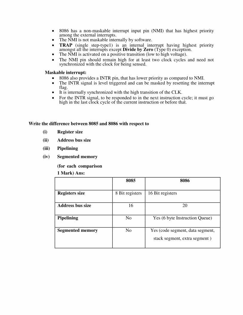
Write the difference between 8085 and 8086 with respect to
(i) Register size
(ii) Address bus size
(iii) Pipelining
(iv) Segmented memory
(for each comparison
1 Mark) Ans:
8085 8086
Registers size 8 Bit registers 16 Bit registers
Address bus size 16 20
Pipelining No Yes (6 byte Instruction Queue)
Segmented memory No Yes (code segment, data segment,
stack segment, extra segment )
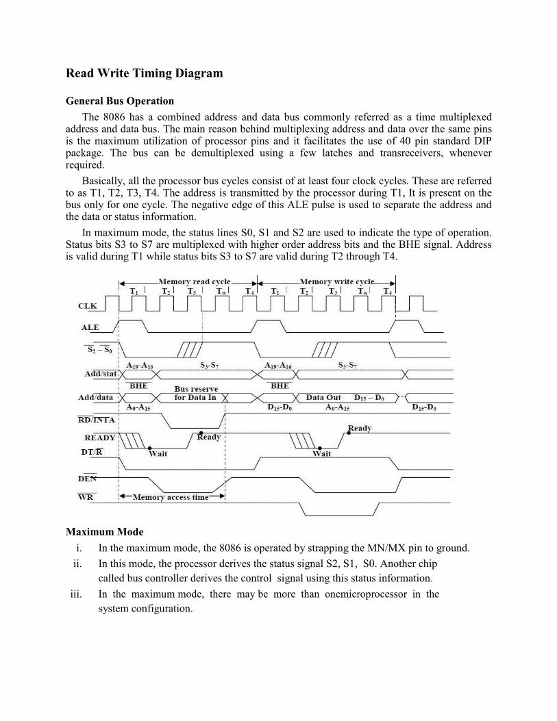
Read Write Timing Diagram
General Bus Operation
The 8086 has a combined address and data bus commonly referred as a time multiplexed address and data bus. The main reason behind multiplexing address and data over the same pins is the maximum utilization of processor pins and it facilitates the use of 40 pin standard DIP package. The bus can be demultiplexed using a few latches and transreceivers, whenever required.
Basically, all the processor bus cycles consist of at least four clock cycles. These are referred to as T1, T2, T3, T4. The address is transmitted by the processor during T1, It is present on the bus only for one cycle. The negative edge of this ALE pulse is used to separate the address and the data or status information.
In maximum mode, the status lines S0, S1 and S2 are used to indicate the type of operation. Status bits S3 to S7 are multiplexed with higher order address bits and the BHE signal. Address is valid during T1 while status bits S3 to S7 are valid during T2 through T4.
Maximum Mode
i. In the maximum mode, the 8086 is operated by strapping the MN/MX pin to ground.
ii. In this mode, the processor derives the status signal S2, S1, S0. Another chip called bus controller derives the control signal using this status information.
iii. In the maximum mode, there may be more than onemicroprocessor in the
system configuration.
Minimum Mode
i. In a minimum mode 8086 system, the microprocessor 8086is operated in
minimum mode by strapping its MN/MX pin to logic 1.
ii. In this mode, all the control signals are given out by the microprocessor chip itself.

Topic 3 : Instruction Set of 8086 Microprocessor
Instruction Set of 8086 The 8086 instructions are categorized into the following main types.
i. Data Copy / Transfer Instructions
ii. Arithmetic and Logical Instructions
iii. Branch Instructions
iv. Loop Instructions
v. Machine Control Instructions
vi. Flag Manipulation Instructions
vii. Shift and Rotate Instructions
viii. String Instructions
Data Copy / Transfer Instructions :
MOV :
This instruction copies a word or a byte of data from some source to a destination. The destination can be a register or a memory location. The source can be a register, a memory location, or an immediate number.
MOV AX,BX MOV AX,5000H MOV AX,[SI] MOV AX,[2000H] MOV AX,50H[BX] MOV [734AH],BX MOV DS,CX MOV CL,[357AH]
Direct loading of the segment registers with immediate data is not permitted.
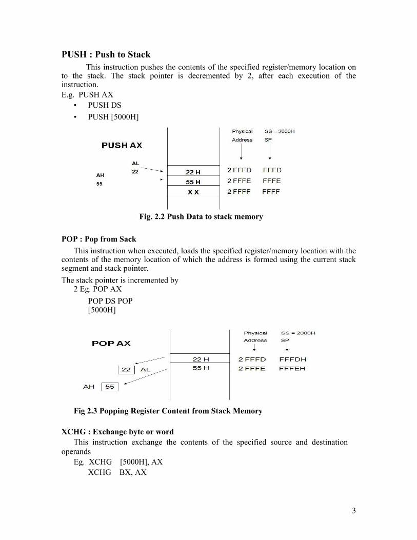
PUSH : Push to Stack
This instruction pushes the contents of the specified register/memory location on to the stack. The stack pointer is decremented by 2, after each execution of the instruction. E.g. PUSH AX
• PUSH DS
• PUSH [5000H]
Fig. 2.2 Push Data to stack memory
POP : Pop from Sack
This instruction when executed, loads the specified register/memory location with the contents of the memory location of which the address is formed using the current stack segment and stack pointer. The stack pointer is incremented by
2 Eg. POP AX
POP DS POP [5000H]
Fig 2.3 Popping Register Content from Stack Memory
XCHG : Exchange byte or word This instruction exchange the contents of the specified source and destination
operands
Eg. XCHG [5000H], AX
XCHG BX, AX
3
XLAT : Translate byte using look-up table Eg. LEA BX, TABLE1
MOV AL, 04H XLAT
Simple input and output port transfer Instructions:
IN: Copy a byte or word from specified port to accumulator. Eg. IN AL,03H
IN AX,DX
OUT: Copy a byte or word from accumulator specified port. Eg. OUT 03H, AL
OUT DX, AX
LEA :
Load effective address of operand in specified register. [reg] offset portion of address in DS Eg. LEA reg, offset
LDS: Load DS register and other specified register from memory. [reg] [mem] [DS] [mem + 2] Eg. LDS reg, mem
LES: Load ES register and other specified register from memory. [reg] [mem] [ES] [mem + 2] Eg. LES reg, mem
Flag transfer instructions: LAHF:
Load (copy to) AH with the low byte the flag register. [AH] [ Flags low byte] Eg. LAHF
4
SAHF:
Store (copy) AH register to low byte of flag register. [Flags low byte] [AH] Eg. SAHF
PUSHF: Copy flag register to top of stack. [SP] [SP] – 2
[[SP]] [Flags]
Eg. PUSHF
POPF : Copy word at top of stack to flag register. [Flags] [[SP]]
[SP] [SP] + 2
Arithmetic Instructions:
The 8086 provides many arithmetic operations: addition, subtraction, negation, multiplication and comparing two values.
ADD :
The add instruction adds the contents of the source operand to the destination operand. Eg.
ADC : Add with Carry
This instruction performs the same operation as ADD instruction, but adds the carry flag to the result.
Eg. ADC
ADC
ADC
ADC
ADC
5
0100H AX, BX AX, [SI] AX, [5000]
[5000], 0100H
ADD AX, 0100H
ADD AX, BX ADD
AX, [SI] ADD AX,
[5000H]
ADD [5000H], 0100H ADD 0100H
SUB : Subtract
The subtract instruction subtracts the source operand from the destination operand and the result is left in the destination operand.
Eg. SUB AX, 0100H
SUB AX, BX SUB AX, [5000H] SUB [5000H], 0100H
SBB : Subtract with Borrow
The subtract with borrow instruction subtracts the source operand and the borrow flag (CF) which may reflect the result of the previous calculations, from the
destination operand Eg.
INC : Increment
This instruction increases the contents of the specified Register or memory location by 1. Immediate data cannot be operand of this instruction.
Eg. INC AX INC
[BX] INC
[5000H]
DEC : Decrement
The decrement instruction subtracts 1 from the contents of the specified register or memory location.
Eg. DEC AX DEC [5000H]
NEG : Negate
The negate instruction forms 2‟s complement of the specified destination in the instruction. The destination can be a register or a memory location. This instruction can be implemented by inverting each bit and adding 1 to it.
Eg. NEG AL
AL = 0011 0101 35H Replace number in AL with its 2‟s complement AL = 1100 1011 = CBH
CMP : Compare
This instruction compares the source operand, which may be a register or an immediate data or a memory location, with a destination operand that may be a
6
SBB AX, 0100H SBB AX, BX SBB AX, [5000H]
SBB [5000H], 0100H
register or a memory location
Eg. CMP BX, 0100H CMP
AX, 0100H
CMP [5000H], 0100H CMP BX, [SI] CMP BX, CX
MUL :Unsigned Multiplication Byte or Word This instruction multiplies an unsigned byte or word by the contents of AL.
Eg. MUL BH ; (AX) (AL) x (BH)
MUL CX ; (DX)(AX) (AX) x (CX)
MUL WORD PTR [SI] ; (DX)(AX) (AX) x ([SI])
IMUL :Signed Multiplication
This instruction multiplies a signed byte in source operand by a signed byte in AL or a signed word in source operand by a signed word in AX.
Eg. IMUL BH
IMUL CX
IMUL [SI]
CBW : Convert Signed Byte to Word
This instruction copies the sign of a byte in AL to all the bits in AH. AH is then said to be sign extension of AL.
Eg. CBW
AX= 0000 0000 1001 1000 Convert signed byte in AL signed word in AX. Result in AX = 1111 1111 1001 1000
CWD : Convert Signed Word to Double Word
This instruction copies the sign of a byte in AL to all the bits in AH. AH is then said to be sign extension of AL.
Eg. CWD
Convert signed word in AX to signed double word in DX : AX DX= 1111 1111 1111 1111 Result in AX = 1111 0000 1100 0001
DIV : Unsigned division
This instruction is used to divide an unsigned word by a byte or to divide an unsigned double word by a word.
Eg. DIV CL ; Word in AX / byte in CL
; Quotient in AL, remainder in AH
DIV CX ; Double word in DX and AX / word
; in CX, and Quotient in AX,
; remainder in DX
7
AAA : ASCII Adjust After Addition
The AAA instruction is executed aftr an ADD instruction that adds two ASCII coded operand to give a byte of result in AL. The AAA instruction converts the resulting contents of Al to a unpacked decimal digits.
Eg. ADD CL, DL ; [CL] = 32H = ASCII for 2 ; [DL] = 35H = ASCII for 5
; Result [CL] = 67H
MOV AL, CL ; Move ASCII result into AL since
; AAA adjust only [AL]
AAA ; [AL]=07, unpacked BCD for 7
AAS : ASCII Adjust AL after Subtraction
This instruction corrects the result in AL register after subtracting two unpacked ASCII operands. The result is in unpacked decimal format. The procedure is similar to AAA instruction except for the subtraction of 06 from AL.
AAM : ASCII Adjust after Multiplication This instruction, after execution, converts the product available In AL into unpacked
BCD format.
Eg. MOV AL, 04 ; AL = 04
MOV BL ,09 ; BL = 09
MUL BL ; AX = AL*BL ; AX=24H
AAM ; AH = 03, AL=06
AAD : ASCII Adjust before Division
This instruction converts two unpacked BCD digits in AH and AL to the equivalent binary number in AL. This adjustment must be made before dividing the two unpacked BCD digits in AX by an unpacked BCD byte. In the instruction sequence, this instruction appears Before DIV instruction.
Eg. AX 05 08 AAD result in AL 00 3A 58D = 3A H in AL
The result of AAD execution will give the hexadecimal number 3A in AL and 00 in AH. Where 3A is the hexadecimal Equivalent of 58 (decimal).
DAA : Decimal Adjust Accumulator
This instruction is used to convert the result of the addition of two packed BCD numbers to a valid BCD number. The result has to be only in AL.
Eg. AL = 53CL = 29
ADD AL, CL ; AL (AL) + (CL)
; AL 53 + 29
; AL 7C
DAA ; AL 7C + 06 (as C>9)
; AL 82
8
DAS : Decimal Adjust after Subtraction
This instruction converts the result of the subtraction of two packed BCD numbers to a valid BCD number. The subtraction has to be in AL only.
Eg. AL = 75, BH = 46
SUB AL, BH ; AL 2 F = (AL) - (BH)
; AF = 1
DAS ; AL 2 9 (as F>9, F - 6 = 9)
Logical Instructions AND : Logical AND
This instruction bit by bit ANDs the source operand that may be an immediate
register or a memory location to the destination operand that may a register or a memory location. The result is stored in the destination operand.
Eg. AND AX, 0008H AND AX, BX
OR : Logical OR
This instruction bit by bit ORs the source operand that may be an immediate , register or a memory location to the destination operand that may a register or a memory location. The result is stored in the destination operand.
Eg. OR AX, 0008H OR AX, BX
NOT : Logical Invert
This instruction complements the contents of an operand register or a memory location, bit by bit.
Eg. NOT AX NOT [5000H]
XOR : Logical Exclusive OR
This instruction bit by bit XORs the source operand that may be an immediate , register or a memory location to the destination operand that may a register or a memory location. The result is stored in the destination operand.
Eg. XOR AX, 0098H XOR AX, BX
TEST : Logical Compare Instruction
The TEST instruction performs a bit by bit logical AND operation on the two operands. The result of this ANDing operation is not available for further use, but flags
are affected.
Eg.TEST AX, BX
TEST [0500], 06H
9
SAL/SHL : SAL / SHL destination, count.
SAL and SHL are two mnemonics for the same instruction. This instruction shifts each bit in the specified destination to the left and 0 is stored at LSB position. The MSB is shifted into the carry flag. The destination can be a byte or a word.
It can be in a register or in a memory location. The number of shifts is indicated by count.
Eg
.
SHR : SHR destination, count
This instruction shifts each bit in the specified destination to the right and 0 is stored at MSB position. The LSB is shifted into the carry flag. The destination can be a byte or a word.
It can be a register or in a memory location. The number of shifts is indicated by
count.
Eg. SHR CX, 1
MOV CL, 05H
SHR AX, CL
SAR : SAR destination, count
This instruction shifts each bit in the specified destination some number of bit positions to the right. As a bit is shifted out of the MSB position, a copy of the old MSB is put in the MSB position. The LSB will be shifted into CF.
Eg. SAR BL, 1
MOV CL, 04H
SAR DX, CL
ROL Instruction : ROL destination, count
This instruction rotates all bits in a specified byte or word to the left some number of bit positions. MSB is placed as a new LSB and a new CF.
Eg. ROL CX, 1
MOV CL, 03H
ROL BL, CL
ROR Instruction : ROR destination, count
This instruction rotates all bits in a specified byte or word to the right some number of bit positions. LSB is placed as a new MSB and a new CF.
Eg. ROR CX, 1
MOV CL, 03H
ROR BL, CL
SAL CX, 1 SAL AX, CL

10

RCL Instruction : RCL destination, count
This instruction rotates all bits in a specified byte or word some number of bit positions to the left along with the carry flag. MSB is placed as a new carry and previous carry is place as new LSB.
Eg. RCL CX, 1
MOV CL, 04H
RCL AL, CL
RCR Instruction : RCR destination, count
This instruction rotates all bits in a specified byte or word some number of bit positions to the right along with the carry flag. LSB is placed as a new carry and previous carry is place as new MSB.
Eg. RCR CX, 1
MOV CL, 04H
RCR AL, CL
ROR Instruction : ROR destination, count
This instruction rotates all bits in a specified byte or word to the right some number of bit positions. LSB is placed as a new MSB and a new CF.
Eg. ROR CX, 1
MOV CL, 03H
ROR BL, CL
RCL Instruction : RCL destination, count
This instruction rotates all bits in a specified byte or word some number of bit positions to the left along with the carry flag. MSB is placed as a new carry and previous carry is place as new LSB.
Eg. RCL CX, 1 MOV CL, 04H RCL AL, CL
RCR Instruction : RCR destination, count
This instruction rotates all bits in a specified byte or word some number of bit positions to the right along with the carry flag. LSB is placed as a new carry and previous carry is place as new MSB.
Eg. RCR CX, 1
MOV CL, 04H
RCR AL, CL
11
Branch Instructions :
Branch Instructions transfers the flow of execution of the program to a new address specified in the instruction directly or indirectly. When this type of instruction is executed, the CS and IP registers get loaded with new values of CS and IP corresponding to the location to be transferred.
The Branch Instructions are classified into two types i. Unconditional Branch Instructions.
ii. Conditional Branch Instructions.
Unconditional Branch Instructions :
In Unconditional control transfer instructions, the execution control is transferred to the specified location independent of any status or condition. The CS and IP are unconditionally modified to the new CS and IP.
CALL : Unconditional Call
This instruction is used to call a Subroutine (Procedure) from a main program. Address of procedure may be specified directly or indirectly.
There are two types of procedure depending upon whether it is available in the same segment or in another segment.
i. Near CALL i.e., ±32K displacement.
ii. For CALL i.e., anywhere outside the segment.
On execution this instruction stores the incremented IP & CS onto the stack and loads the CS & IP registers with segment and offset addresses of the procedure to be called.
RET: Return from the Procedure.
At the end of the procedure, the RET instruction must be executed. When it is executed, the previously stored content of IP and CS along with Flags are retrieved into the CS, IP and Flag registers from the stack and execution of the main program continues further.
INT N: Interrupt Type N.
In the interrupt structure of 8086, 256 interrupts are defined corresponding to the types from 00H to FFH. When INT N instruction is executed, the type byte N is multiplied by 4 and the contents of IP and CS of the interrupt service routine will be taken from memory block in 0000 segment.
12
INTO: Interrupt on Overflow
This instruction is executed, when the overflow flag OF is set. This is equivalent to a Type 4 Interrupt instruction.
JMP: Unconditional Jump
This instruction unconditionally transfers the control of execution to the specified address using an 8-bit or 16-bit displacement. No Flags are affected by this instruction.
IRET: Return from ISR
When it is executed, the values of IP, CS and Flags are retrieved from the stack to continue the execution of the main program.
LOOP : LOOP Unconditionally
This instruction executes the part of the program from the Label or address specified in the instruction upto the LOOP instruction CX number of times. At each iteration, CX is decremented automatically and JUMP IF NOT ZERO structure.
Example: MOV CX, 0004H MOV BX, 7526H Label 1 MOV AX, CODE OR BX, AX LOOP Label 1
Conditional Branch Instructions
When this instruction is executed, execution control is transferred to the address specified relatively in the instruction, provided the condition implicit in the Opcode is satisfied. Otherwise execution continues sequentially.
JZ/JE Label Transfer execution control to address „Label‟, if ZF=1.
JNZ/JNE Label Transfer execution control to address „Label‟, if ZF=0
JS Label Transfer execution control to address „Label‟, if SF=1.
JNS Label Transfer execution control to address „Label‟, if SF=0.
JO Label Transfer execution control to address „Label‟, if OF=1.
13
JNO Label Transfer execution control to address „Label‟, if OF=0.
JNP Label Transfer execution control to address „Label‟, if PF=0.
JP Label Transfer execution control to address „Label‟, if PF=1.
JB Label Transfer execution control to address „Label‟, if CF=1.
JNB Label Transfer execution control to address „Label‟, if CF=0.
JCXZ Label Transfer execution control to address „Label‟, if CX=0
Conditional LOOP Instructions.
LOOPZ / LOOPE Label Loop through a sequence of instructions from label while ZF=1 and CX=0.
LOOPNZ / LOOPENE Label Loop through a sequence of instructions from label while ZF=1 and CX=0.
String Manipulation Instructions
A series of data byte or word available in memory at consecutive locations, to be referred as Byte String or Word String. A String of characters may be located in consecutive memory locations, where each character may be represented by its ASCII equivalent.
The 8086 supports a set of more powerful instructions for string manipulations for referring to a string, two parameters are required.
I. Starting and End Address of the String. II. Length of the String.
The length of the string is usually stored as count in the CX register.The incrementing or decrementing of the pointer, in string instructions, depends upon the Direction Flag (DF) Status. If it is a Byte string operation, the index registers are updated
14
by one. On the other hand, if it is a word string operation, the index registers are updated by two.
REP : Repeat Instruction Prefix
This instruction is used as a prefix to other instructions, the instruction to which the REP prefix is provided, is executed repeatedly until the CX register becomes zero (at each iteration CX is automatically decremented by one).
i. REPE / REPZ- repeat operation while equal / zero.
ii. REPNE / REPNZ - repeat operation while not equal / not zero.
These are used for CMPS, SCAS instructions only, as instruction prefixes. MOVSB / MOVSW :Move String Byte or String Word
Suppose a string of bytes stored in a set of consecutive memory locations is to be moved to another set of destination locations.The starting byte of source string is located in the memory location whose address may be computed using SI (Source Index) and DS (Data Segment) contents.
The starting address of the destination locations where this string has to be relocated is given by DI (Destination Index) and ES (Extra Segment) contents.
CMPS : Compare String Byte or String Word
The CMPS instruction can be used to compare two strings of byte or words. The length of the string must be stored in the register CX. If both the byte or word strings are equal, zero Flag is set.
The REP instruction Prefix is used to repeat the operation till CX (counter) becomes zero or the condition specified by the REP Prefix is False.
SCAN : Scan String Byte or String Word
This instruction scans a string of bytes or words for an operand byte or word specified in the register AL or AX. The String is pointed to by ES:DI register pair. The length of the string s stored in CX. The DF controls the mode for scanning of the string. Whenever a match to the specified operand, is found in the string, execution stops and the zero Flag is set. If no match is found, the zero flag is reset.
LODS : Load String Byte or String Word
The LODS instruction loads the AL / AX register by the content of a string pointed to by DS : SI register pair. The SI is modified automatically depending upon DF, If it is a byte transfer (LODSB), the SI is modified by one and if it is a word transfer (LODSW), the SI is modified by two. No other Flags are affected by this instruction.
15
STOS : Store String Byte or String Word
The STOS instruction Stores the AL / AX register contents to a location in the string pointer by ES : DI register pair. The DI is modified accordingly, No Flags are affected by this instruction.
The direction Flag controls the String instruction execution, The source index SI and Destination Index DI are modified after each iteration automatically. If DF=1, then the execution follows autodecrement mode, SI and DI are decremented automatically after each iteration. If DF=0, then the execution follows autoincrement mode. In this mode, SI and DI are incremented automatically after each iteration.
Flag Manipulation and a Processor Control Instructions
These instructions control the functioning of the available hardware inside the
processor chip. These instructions are categorized into two types:
1. Flag Manipulation instructions.
2. Machine Control instructions.
Flag Manipulation instructions
The Flag manipulation instructions directly modify some of the Flags of 8086. i. CLC – Clear Carry Flag.
ii. CMC – Complement Carry Flag.
iii. STC – Set Carry Flag.
iv. CLD – Clear Direction Flag.
v. STD – Set Direction Flag.
vi. CLI – Clear Interrupt Flag.
vii. STI – Set Interrupt Flag.
Machine Control instructions The Machine control instructions control the bus usage and execution
i. WAIT – Wait for Test input pin to go low.
ii. HLT – Halt the process.
iii. NOP – No operation.
iv. ESC – Escape to external device like NDP
v. LOCK – Bus lock instruction prefix.
16

Describe various addressing mode used in 8086 instructions with example. (Any 4 addressing modes : ½ Mark explanation, ½ Mark one example of each)
Ans: Different addressing modes of 8086 :
1. Immediate : In this addressing mode, immediate data is a part of instruction, and appears in the
form of
successive byte or word.
E.g.: MOV AX, 005OH
2. Direct : In the direct addressing mode, a 16 bit address (offset) is directly specified in the
instruction as
a part of it.
E.g.:. MOV AX ,[1 0 0 0 H]
3. Register : In register addressing mode, the data is stored in a register and it is referred using the
particular register. All the registers except IP may be used in this mode.
E.g.:. 1)MOV AX,BX 2)ROR AL,CL 3) AND AL,BL
4. Register Indirect: In this addressing mode, the address of the memory location which contains
data or
operand is determined in an indirect way using offset registers. The offset address of data is in
either BX or
SI or DI register. The default segment register is either DS or ES.
e.g. MOV AX, BX 5. Indexed : In this addressing mode offset of the operand is stored in one of the index register. DS
and ES
are the default segments for index registers SI and DI respectively
e.g. MOV AX, SI 6. Register Relative : In this addressing mode, the data is available at an effective address formed
by
adding an 8-bit or 16-bit displacement with the content of any one of the registers BX, BP, SI and
DI in the
default either DS or ES segment.
e.g. MOV AX, 50HBX 7. Based Indexed: In this addressing mode, the effective address of the data is formed by adding
the
content of a base register (any one of BX or BP) to the content of an index register (any one of SI
or DI).
The default segment register may be ES or DS.
e.g MOV AX, BX SI 8. Relative Based Indexed : The effective address is formed by adding an 8-bit or 16-bit
displacement
with the sum of contents of any one of the base register (BX or BP) and any one of the index
registers in a
default segment.
e.g. MOV AX, 50HBXSI 9. Implied addressing mode: No address is required because the address or the operand is implied in the instruction itself.
E.g NOP,STC,CLI,CLD,STD
Addressing Modes
Addressing modes of 8086 When 8086 executes an instruction, it performs the specified function on data. These data are called its operands and may be part of the instruction, reside in one of the internal registers of the microprocessor, stored at an address in memory or held at an I/O port, to access these different types of operands, the 8086 is provided with various addressing modes (Data Addressing Modes). Data Addressing Modes of 8086 The 8086 has 12 addressing modes. The various 8086 addressing modes can be classified into five groups.
A. Addressing modes for accessing immediate and register data (register and immediate modes).
B. Addressing modes for accessing data in memory (memory modes)
C. Addressing modes for accessing I/O ports (I/O modes)
D. Relative addressing mode
E. Implied addressing mode
8086 ADDRESSING MODES
A. Immediate addressing mode:
In this mode, 8 or 16 bit data can be specified as part of the instruction.
OP Code Immediate Operand
Example 1 : MOV CL, 03 H Moves the 8 bit data 03 H into CL
Example 2 : MOV DX, 0525 H
Moves the 16 bit data 0525 H into DX In the above two examples, the source operand is in immediate mode and the destination operand is in register mode.
A constant such as “VALUE” can be defined by the assembler EQUATE directive such as VALUE EQU 35H Example : MOV BH, VALUE
Used to load 35 H into BH
Register addressing mode : The operand to be accessed is specified as residing in an internal register of 8086. Fig. below shows internal registers, any one can be used as a source or destination operand, however only the data registers can be accessed as either a byte or word.
17
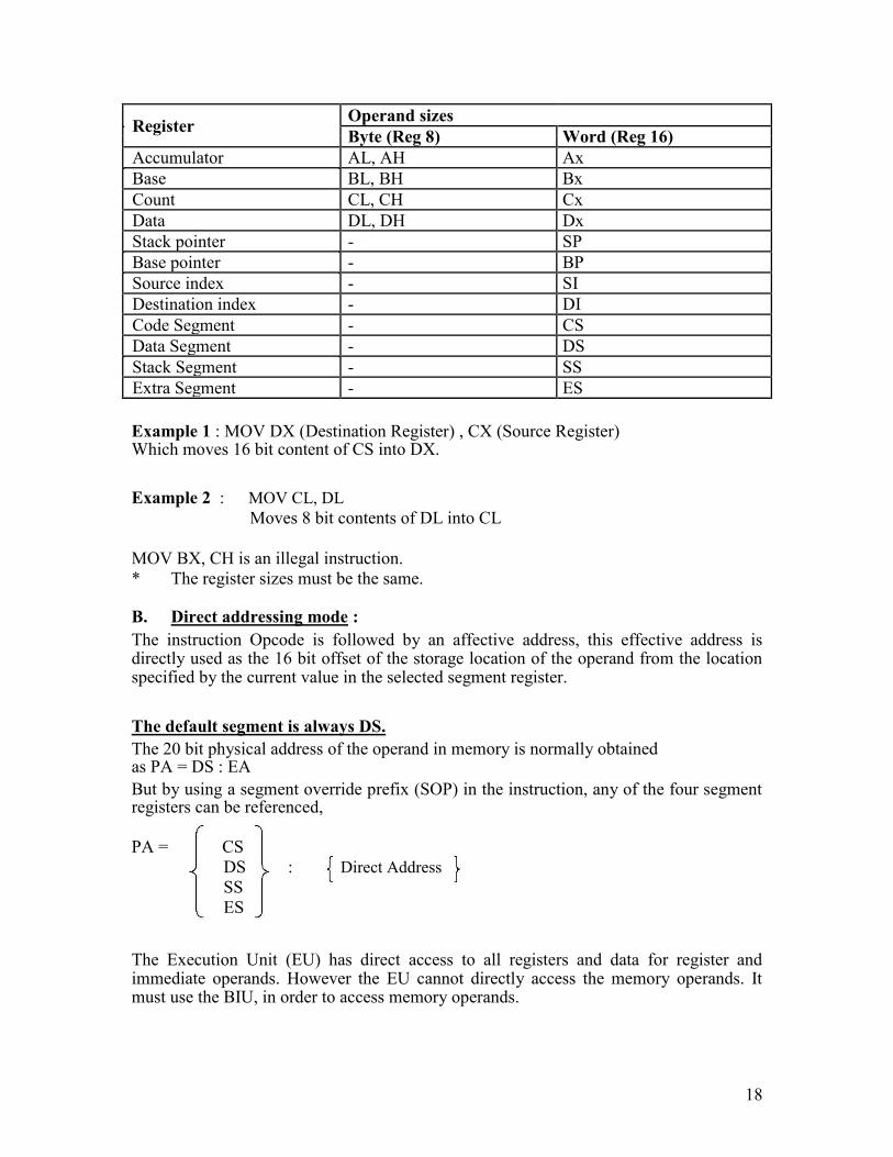
Register Operand sizes
Byte (Reg 8) Word (Reg 16)
Accumulator AL, AH Ax
Base BL, BH Bx
Count CL, CH Cx
Data DL, DH Dx
Stack pointer - SP
Base pointer - BP
Source index - SI
Destination index - DI
Code Segment - CS
Data Segment - DS
Stack Segment - SS
Extra Segment - ES
Example 1 : MOV DX (Destination Register) , CX (Source Register) Which moves 16 bit content of CS into DX.
Example 2 : MOV CL, DL
Moves 8 bit contents of DL into CL
MOV BX, CH is an illegal instruction.
* The register sizes must be the same.
B. Direct addressing mode : The instruction Opcode is followed by an affective address, this effective address is directly used as the 16 bit offset of the storage location of the operand from the location specified by the current value in the selected segment register.
The default segment is always DS. The 20 bit physical address of the operand in memory is normally obtained as PA = DS : EA But by using a segment override prefix (SOP) in the instruction, any of the four segment registers can be referenced,
PA = CS
DS : Direct Address
SS
ES The Execution Unit (EU) has direct access to all registers and data for register and immediate operands. However the EU cannot directly access the memory operands. It must use the BIU, in order to access memory operands.
18
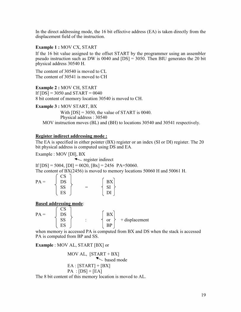
In the direct addressing mode, the 16 bit effective address (EA) is taken directly from the displacement field of the instruction.
Example 1 : MOV CX, START If the 16 bit value assigned to the offset START by the programmer using an assembler pseudo instruction such as DW is 0040 and [DS] = 3050. Then BIU generates the 20 bit physical address 30540 H. The content of 30540 is moved to CL
The content of 30541 is moved to CH
Example 2 : MOV CH, START
If [DS] = 3050 and START = 0040
8 bit content of memory location 30540 is moved to CH. Example 3 : MOV START, BX
With [DS] = 3050, the value of START is 0040. Physical address : 30540
MOV instruction moves (BL) and (BH) to locations 30540 and 30541 respectively.
Register indirect addressing mode : The EA is specified in either pointer (BX) register or an index (SI or DI) register. The 20 bit physical address is computed using DS and EA. Example : MOV [DI], BX
register indirect If [DS] = 5004, [DI] = 0020, [Bx] = 2456 PA=50060.
The content of BX(2456) is moved to memory locations 50060 H and 50061 H.
CS
PA = DS BX
SS = SI
ES DI
Based addressing mode:
CS
PA = DS BX
SS : or + displacement
ES BP when memory is accessed PA is computed from BX and DS when the stack is accessed PA is computed from BP and SS. Example : MOV AL, START [BX] or
MOV AL, [START + BX]
based mode
EA : [START] + [BX]
PA : [DS] + [EA] The 8 bit content of this memory location is moved to AL.
19

Indexed addressing mode:
CS
PA = DS SI
SS : or + 8 or 16bit displacement
ES DI
Example : MOV BH, START [SI]
PA : [SART] + [SI] + [DS]
The content of this memory is moved into BH.
Based Indexed addressing mode:
CS
PA = DS BX SI
SS : or + or + 8 or 16bit displacement
ES BP DI
Example : MOV ALPHA [SI] [BX], CL
If [BX] = 0200, ALPHA – 08, [SI] = 1000 H and [DS] = 3000
Physical address (PA) = 31208
8 bit content of CL is moved to 31208 memory address.
String addressing mode: The string instructions automatically assume SI to point to the first byte or word of the source operand and DI to point to the first byte or word of the destination operand. The contents of SI and DI are automatically incremented (by clearing DF to 0 by CLD instruction) to point to the next byte or word. Example : MOV S BYTE
If [DF] = 0, [DS] = 2000 H, [SI] = 0500, [ES] = 4000, [DI] = 0300
Source address : 20500, assume it contains 38 PA : [DS] + [SI]
Destination address : [ES] + [DI] = 40300, assume it contains 45
After executing MOV S BYTE,
[40300] = 38 [SI] = 0501 incremented [DI] = 0301
C. I/O mode (direct) :
Port number is an 8 bit immediate operand. Example : OUT 05 H, AL
Outputs [AL] to 8 bit port 05 H
I/O mode (indirect):
The port number is taken from DX.
Example 1 : INAL, DX
20
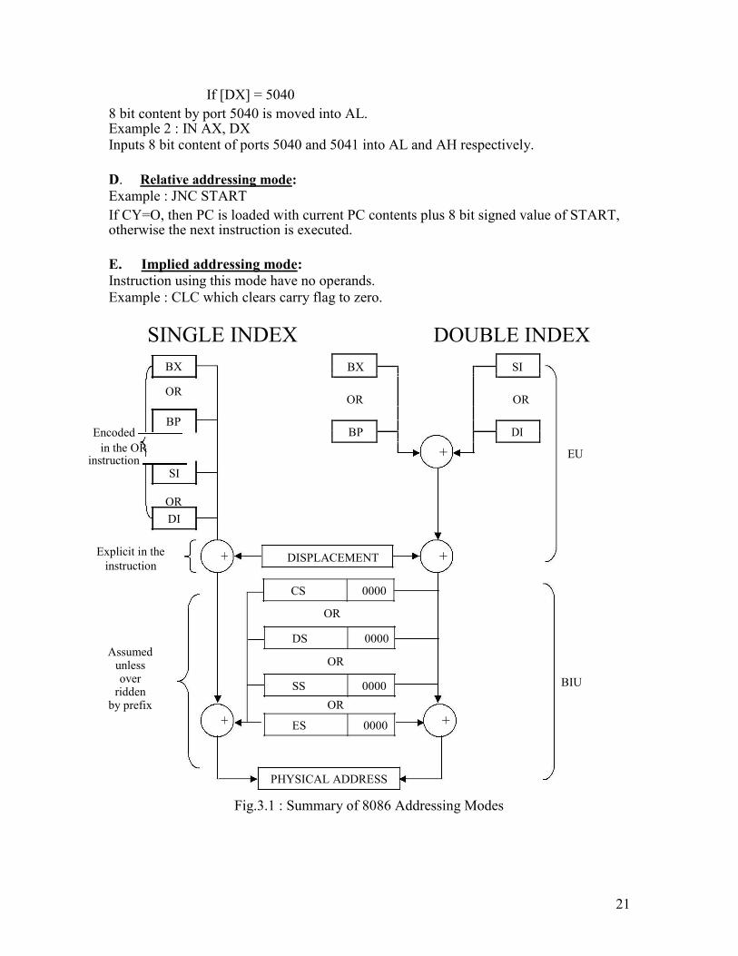
If [DX] = 5040 8 bit content by port 5040 is moved into AL. Example 2 : IN AX, DX Inputs 8 bit content of ports 5040 and 5041 into AL and AH respectively.
D. Relative addressing mode:
Example : JNC START If CY=O, then PC is loaded with current PC contents plus 8 bit signed value of START, otherwise the next instruction is executed.
E. Implied addressing mode:
Instruction using this mode have no operands.
Example : CLC which clears carry flag to zero.
SINGLE INDEX DOUBLE INDEX
BX
OR
BP
Encoded in the OR
instruction SI
OR DI
Explicit in the
instruction
Assumed unless over
ridden by prefix
BX
SI
OR OR
BP
+
DI
EU
+ DISPLACEMENT +
CS 0000
OR
DS 0000
OR
SS 0000 BIU
OR
+ ES 0000 +
PHYSICAL ADDRESS
Fig.3.1 : Summary of 8086 Addressing Modes
21
Special functions of general-purpose registers: AX & DX registers: In 8 bit multiplication, one of the operands must be in AL. The other operand can be a byte in memory location or in another 8 bit register. The resulting 16 bit product is stored in AX, with AH storing the MS byte.
In 16 bit multiplication, one of the operands must be in AX. The other operand can be a word in memory location or in another 16 bit register. The resulting 32 bit product is stored in DX and AX, with DX storing the MS word and AX storing the LS word.
BX register : In instructions where we need to specify in a general purpose register the 16 bit effective address of a memory location, the register BX is used (register indirect).
CX register : In Loop Instructions, CX register will be always used as the implied counter.
In I/O instructions, the 8086 receives into or sends out data from AX or AL depending as a word or byte operation. In these instructions the port address, if greater than FFH has to be given as the contents of DX register. Ex : IN AL, DX
DX register will have 16 bit address of the I/P device
Physical Address (PA) generation : Generally Physical Address (20 Bit) = Segment Base Address (SBA)
+ Effective Address (EA) Code Segment : Physical Address (PA) = CS Base Address
+ Instruction Pointer (IP) Data Segment (DS) PA = DS Base Address + EA can be in BX or SI or DI Stack Segment (SS) PA + SS Base Address + EA can be SP or BP Extra Segment (ES) PA = ES Base Address + EA in DI
Instruction Format : The 8086 instruction sizes vary from one to six bytes. The OP code occupies six bytes and it defines the operation to be carried out by the instruction. Register Direct bit (D) occupies one bit. It defines whether the register operand in byte 2 is the source or destination operand.
22

D=1 Specifies that the register operand is the destination operand. D=0 indicates that the register is a source operand.
Data size bit (W) defines whether the operation to be performed is an 8 bit or 16 bit data
W=0 indicates 8 bit operation
W=1 indicates 16 bit operation
7 2 1 0 7 6 5 4 3 2 1 0 Byte 3 Byte 4
Opcode
D W
MOD
REG R/M
Low Disp/ High Disp/
DATA DATA
OR
Byte 1
Byte 2
DIRECT
DIRECT
ADDRESS LOW ADDRESS HIGH
BYTE BYTE
Register Operand/Register to use EA Calculation
Register Operand/Extension of opcode
Register mode/Memory mode with displacement length
Word/byte operation
Direction is to register/from register
Operation code
The second byte of the instruction usually identifies whether one of the operands is in memory or whether both are registers.
This byte contains 3 fields. These are the mode (MOD) field, the register (REG) field and the Register/Memory (R/M) field.
MOD (2 bits) Interpretation
00 Memory mode with no displacement follows except for 16 bit displacement when R/M=110
01 Memory mode with 8 bit displacement
10 Memory mode with 16 bit displacement
11 Register mode (no displacement)
Register field occupies 3 bits. It defines the register for the first operand which is specified as source or destination by the D bit.
23
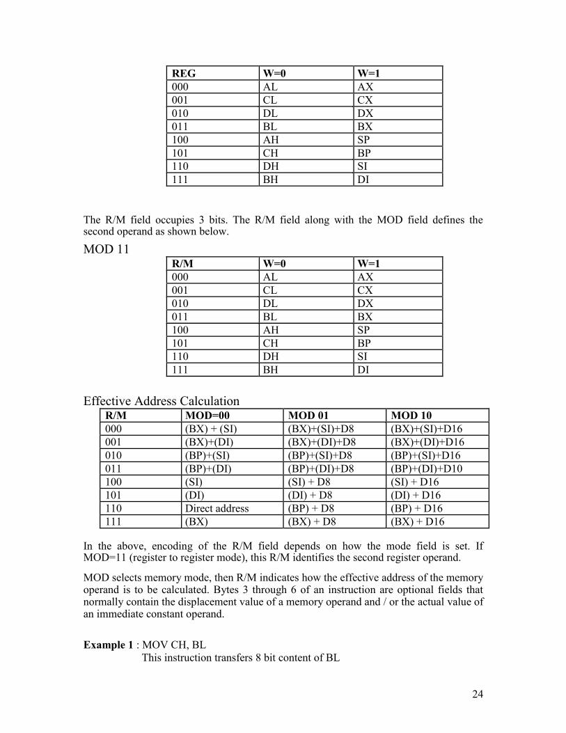
REG W=0 W=1
000 AL AX
001 CL CX
010 DL DX
011 BL BX
100 AH SP
101 CH BP
110 DH SI
111 BH DI The R/M field occupies 3 bits. The R/M field along with the MOD field defines the second operand as shown below.
MOD 11
R/M W=0 W=1
000 AL AX
001 CL CX
010 DL DX
011 BL BX
100 AH SP
101 CH BP
110 DH SI
111 BH DI
Effective Address Calculation
R/M MOD=00 MOD 01 MOD 10
000 (BX) + (SI) (BX)+(SI)+D8 (BX)+(SI)+D16
001 (BX)+(DI) (BX)+(DI)+D8 (BX)+(DI)+D16
010 (BP)+(SI) (BP)+(SI)+D8 (BP)+(SI)+D16
011 (BP)+(DI) (BP)+(DI)+D8 (BP)+(DI)+D10
100 (SI) (SI) + D8 (SI) + D16
101 (DI) (DI) + D8 (DI) + D16
110 Direct address (BP) + D8 (BP) + D16
111 (BX) (BX) + D8 (BX) + D16
In the above, encoding of the R/M field depends on how the mode field is set. If MOD=11 (register to register mode), this R/M identifies the second register operand. MOD selects memory mode, then R/M indicates how the effective address of the memory operand is to be calculated. Bytes 3 through 6 of an instruction are optional fields that normally contain the displacement value of a memory operand and / or the actual value of an immediate constant operand.
Example 1 : MOV CH, BL
This instruction transfers 8 bit content of BL
24
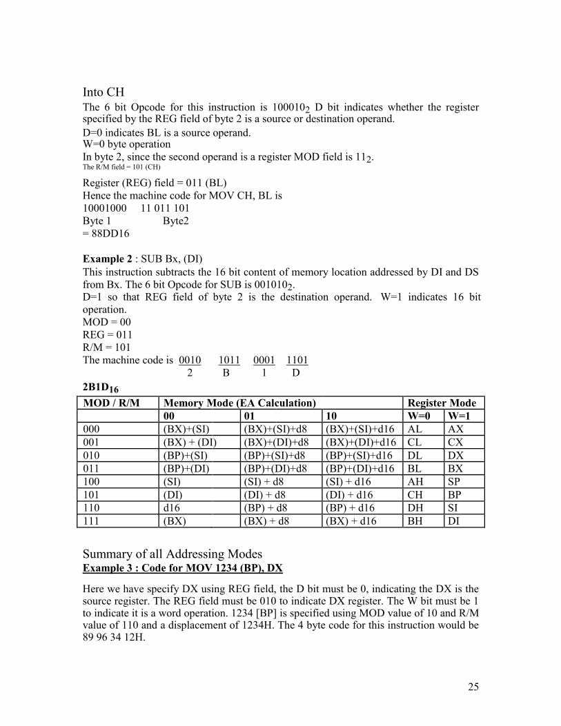
Into CH
The 6 bit Opcode for this instruction is 1000102 D bit indicates whether the register specified by the REG field of byte 2 is a source or destination operand. D=0 indicates BL is a source operand. W=0 byte operation
In byte 2, since the second operand is a register MOD field is 112. The R/M field = 101 (CH)
Register (REG) field = 011 (BL)
Hence the machine code for MOV CH, BL is
10001000 11 011 101
Byte 1 Byte2
= 88DD16
Example 2 : SUB Bx, (DI) This instruction subtracts the 16 bit content of memory location addressed by DI and DS
from Bx. The 6 bit Opcode for SUB is 0010102. D=1 so that REG field of byte 2 is the destination operand. W=1 indicates 16 bit
operation.
MOD = 00
REG = 011
R/M = 101
The machine code is 0010 1011 0001 1101
2 B 1 D
2B1D16
MOD / R/M Memory Mode (EA Calculation) Register Mode
00 01 10 W=0 W=1
000 (BX)+(SI) (BX)+(SI)+d8 (BX)+(SI)+d16 AL AX
001 (BX) + (DI) (BX)+(DI)+d8 (BX)+(DI)+d16 CL CX
010 (BP)+(SI) (BP)+(SI)+d8 (BP)+(SI)+d16 DL DX
011 (BP)+(DI) (BP)+(DI)+d8 (BP)+(DI)+d16 BL BX
100 (SI) (SI) + d8 (SI) + d16 AH SP
101 (DI) (DI) + d8 (DI) + d16 CH BP
110 d16 (BP) + d8 (BP) + d16 DH SI
111 (BX) (BX) + d8 (BX) + d16 BH DI
Summary of all Addressing Modes Example 3 : Code for MOV 1234 (BP), DX
Here we have specify DX using REG field, the D bit must be 0, indicating the DX is the source register. The REG field must be 010 to indicate DX register. The W bit must be 1 to indicate it is a word operation. 1234 [BP] is specified using MOD value of 10 and R/M value of 110 and a displacement of 1234H. The 4 byte code for this instruction would be 89 96 34 12H.
25
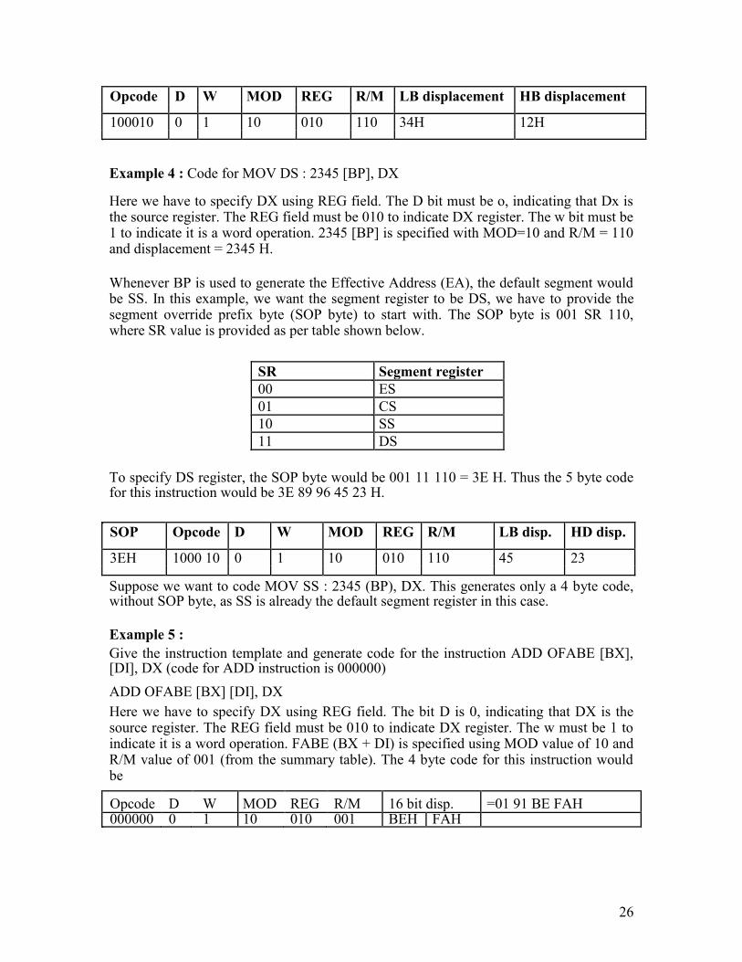
Opcode D W MOD REG R/M LB displacement HB displacement
100010 0 1 10 010 110 34H 12H
Example 4 : Code for MOV DS : 2345 [BP], DX
Here we have to specify DX using REG field. The D bit must be o, indicating that Dx is the source register. The REG field must be 010 to indicate DX register. The w bit must be 1 to indicate it is a word operation. 2345 [BP] is specified with MOD=10 and R/M = 110 and displacement = 2345 H.
Whenever BP is used to generate the Effective Address (EA), the default segment would be SS. In this example, we want the segment register to be DS, we have to provide the segment override prefix byte (SOP byte) to start with. The SOP byte is 001 SR 110, where SR value is provided as per table shown below.
SR Segment register
00 ES
01 CS
10 SS
11 DS
To specify DS register, the SOP byte would be 001 11 110 = 3E H. Thus the 5 byte code for this instruction would be 3E 89 96 45 23 H.
SOP Opcode D W MOD REG R/M LB disp. HD disp.
3EH 1000 10 0 1 10 010 110 45 23 Suppose we want to code MOV SS : 2345 (BP), DX. This generates only a 4 byte code, without SOP byte, as SS is already the default segment register in this case.
Example 5 : Give the instruction template and generate code for the instruction ADD OFABE [BX], [DI], DX (code for ADD instruction is 000000)
ADD OFABE [BX] [DI], DX Here we have to specify DX using REG field. The bit D is 0, indicating that DX is the source register. The REG field must be 010 to indicate DX register. The w must be 1 to indicate it is a word operation. FABE (BX + DI) is specified using MOD value of 10 and R/M value of 001 (from the summary table). The 4 byte code for this instruction would be
Opcode D W MOD REG R/M 16 bit disp. =01 91 BE FAH 000000 0 1 10 010 001 BEH FAH
26
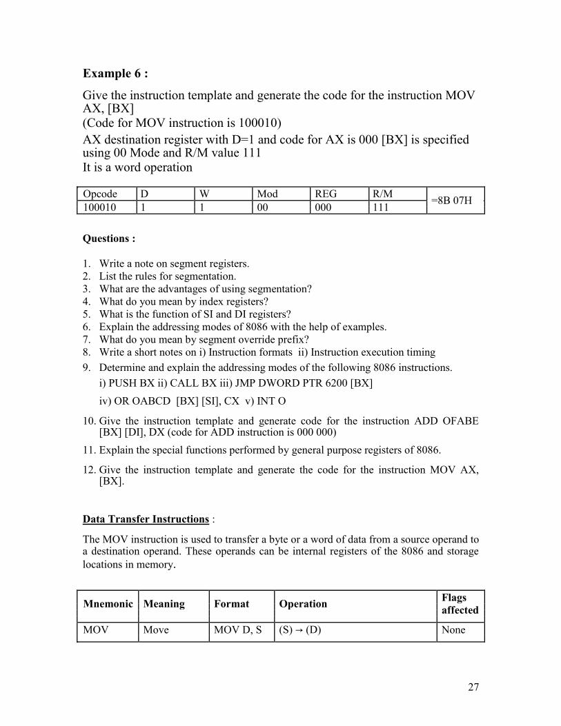
Example 6 : Give the instruction template and generate the code for the instruction MOV AX, [BX]
(Code for MOV instruction is 100010) AX destination register with D=1 and code for AX is 000 [BX] is specified using 00 Mode and R/M value 111
It is a word operation
Opcode D W Mod REG R/M =8B 07H
100010 1 1 00 000 111
Questions :
1. Write a note on segment registers.
2. List the rules for segmentation.
3. What are the advantages of using segmentation?
4. What do you mean by index registers?
5. What is the function of SI and DI registers?
6. Explain the addressing modes of 8086 with the help of examples.
7. What do you mean by segment override prefix?
8. Write a short notes on i) Instruction formats ii) Instruction execution timing 9. Determine and explain the addressing modes of the following 8086 instructions.
i) PUSH BX ii) CALL BX iii) JMP DWORD PTR 6200 [BX]
iv) OR OABCD [BX] [SI], CX v) INT O 10. Give the instruction template and generate code for the instruction ADD OFABE
[BX] [DI], DX (code for ADD instruction is 000 000) 11. Explain the special functions performed by general purpose registers of 8086.
12. Give the instruction template and generate the code for the instruction MOV AX,
[BX].
Data Transfer Instructions : The MOV instruction is used to transfer a byte or a word of data from a source operand to a destination operand. These operands can be internal registers of the 8086 and storage
locations in memory.
Mnemonic Meaning Format Operation Flags
affected
MOV Move MOV D, S (S) → (D) None
27
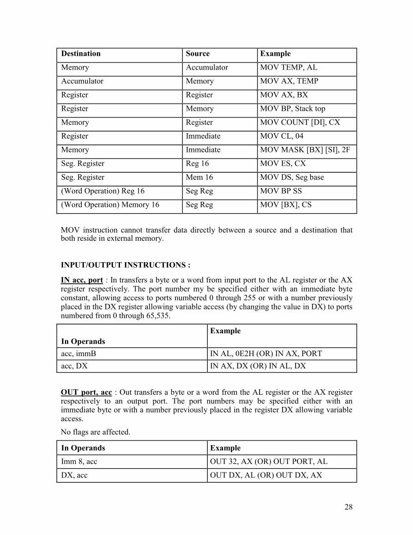
Destination Source Example
Memory Accumulator MOV TEMP, AL
Accumulator Memory MOV AX, TEMP
Register Register MOV AX, BX
Register Memory MOV BP, Stack top
Memory Register MOV COUNT [DI], CX
Register Immediate MOV CL, 04
Memory Immediate MOV MASK [BX] [SI], 2F
Seg. Register Reg 16 MOV ES, CX
Seg. Register Mem 16 MOV DS, Seg base
(Word Operation) Reg 16 Seg Reg MOV BP SS
(Word Operation) Memory 16 Seg Reg MOV [BX], CS
MOV instruction cannot transfer data directly between a source and a destination that both reside in external memory.
INPUT/OUTPUT INSTRUCTIONS : IN acc, port : In transfers a byte or a word from input port to the AL register or the AX register respectively. The port number my be specified either with an immediate byte constant, allowing access to ports numbered 0 through 255 or with a number previously placed in the DX register allowing variable access (by changing the value in DX) to ports numbered from 0 through 65,535.
Example
In Operands
acc, immB IN AL, 0E2H (OR) IN AX, PORT
acc, DX IN AX, DX (OR) IN AL, DX
OUT port, acc : Out transfers a byte or a word from the AL register or the AX register respectively to an output port. The port numbers may be specified either with an immediate byte or with a number previously placed in the register DX allowing variable access.
No flags are affected.
In Operands Example
Imm 8, acc OUT 32, AX (OR) OUT PORT, AL
DX, acc OUT DX, AL (OR) OUT DX, AX
28
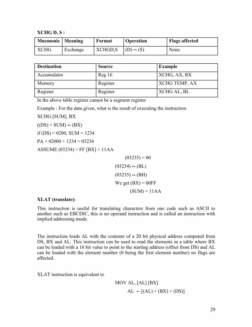
XCHG D, S :
Mnemonic Meaning Format Operation Flags affected
XCHG Exchange XCHGD,S (D) ↔ (S) None
Destination Source Example
Accumulator Reg 16 XCHG, AX, BX
Memory Register XCHG TEMP, AX
Register Register XCHG AL, BL
In the above table register cannot be a segment register Example : For the data given, what is the result of executing the instruction.
XCHG [SUM], BX
((DS) + SUM) ↔ (BX) if (DS) = 0200, SUM = 1234
PA = 02000 + 1234 = 03234
ASSUME (03234) = FF [BX] = 11AA
(03235) = 00
(03234) ↔ (BL)
(03235) ↔ (BH)
We get (BX) = 00FF
(SUM) = 11AA XLAT (translate):
This instruction is useful for translating characters from one code such as ASCII to another such as EBCDIC, this is no operand instruction and is called an instruction with implied addressing mode.
The instruction loads AL with the contents of a 20 bit physical address computed from DS, BX and AL. This instruction can be used to read the elements in a table where BX can be loaded with a 16 bit value to point to the starting address (offset from DS) and AL can be loaded with the element number (0 being the first element number) no flags are affected.
XLAT instruction is equivalent to
MOV AL, [AL] [BX]
AL ← [(AL) + (BX) + (DS)]
29
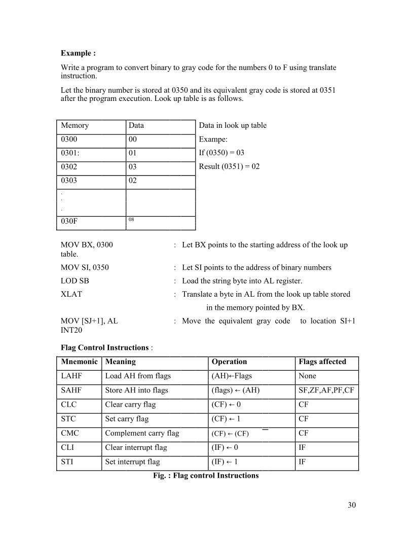
Example : Write a program to convert binary to gray code for the numbers 0 to F using translate instruction.
Let the binary number is stored at 0350 and its equivalent gray code is stored at 0351 after the program execution. Look up table is as follows.
Memory Data Data in look up table
0300 00 Exampe:
If (0350) = 03
0301: 01
Result (0351) = 02
0302 03
0303 02
.
.
.
030F 08
MOV BX, 0300 : Let BX points to the starting address of the look up
table.
MOV SI, 0350 : Let SI points to the address of binary numbers
LOD SB : Load the string byte into AL register.
XLAT : Translate a byte in AL from the look up table stored
in the memory pointed by BX.
MOV [SJ+1], AL : Move the equivalent gray code to location SI+1
INT20
Flag Control Instructions :
Mnemonic Meaning Operation Flags affected
LAHF Load AH from flags (AH)←Flags None
SAHF Store AH into flags (flags) ← (AH) SF,ZF,AF,PF,CF
CLC Clear carry flag (CF) ← 0 CF
STC Set carry flag (CF) ← 1 CF
CMC Complement carry flag
CF
(CF) ← (CF)
CLI Clear interrupt flag (IF) ← 0 IF
STI Set interrupt flag (IF) ← 1 IF
Fig. : Flag control Instructions
30
The first two instructions LAHF and SAHF can be used either to read the flags or to change them respectively notice that the data transfer that takes place is always between the AH register and flag register. For instance, we may want to start an operation with certain flags set or reset. Assume that we want to preset all flags to logic 1. To do this we can first load AH with FF and then execute the SAHF instruction. Example : Write an instruction sequence to save the contents of the 8086‟s flags in memory location MEM1 and then reload the flags with the contents of memory location MEM2. Assume that MEM1 and MEM2 are in the same data segment defined by the current contents of DS. LAHF : Load current flags in AH register
MOV (MEM1), AH : Save in (MEM1)
MOV AH, (MEM2) : Copy the contents of (MEM2)
SAHF : Store AH contents into the flags.
Strings and String Handling Instructions : The 8086 microprocessor is equipped with special instructions to handle string operations. By string we mean a series of data words or bytes that reside in consecutive memory locations. The string instructions of the 8086 permit a programmer to implement operations such as to move data from one block of memory to a block elsewhere in memory. A second type of operation that is easily performed is to scan a string and data elements stored in memory looking for a specific value. Other examples are to compare the elements and two strings together in order to determine whether they are the same or different.
Move String : MOV SB, MOV SW: An element of the string specified by the source index (SI) register with respect to the current data segment (DS) register is moved to the location specified by the destination index (DI) register with respect to the current extra segment (ES) register. The move can be performed on a byte (MOV SB) or a word (MOV SW) of data. After the move is complete, the contents of both SI & DI are automatically incremented or decremented by 1 for a byte move and by 2 for a word move. Address pointers SI and DI increment or decrement depends on how the direction flag DF is set. Example : Block move program using the move string instruction
MOV AX, DATA SEG ADDR
MOV DS, AX
MOV ES, AX
MOV SI, BLK 1 ADDR
MOV DI, BLK 2 ADDR
31

MOV CK, N
CDF ; DF=0 NEXT : MOV SB
LOOP NEXT
HLT
Load and store strings : (LOD SB/LOD SW and STO SB/STO SW)
LOD SB: Loads a byte from a string in memory into AL. The address in SI is used relative to DS to determine the address of the memory location of the string element.
(AL) ← [(DS) + (SI)]
(SI) ← (SI) + 1 LOD SW : The word string element at the physical address derived from DS and SI is to be loaded into AX. SI is automatically incremented by 2.
(AX) ← [(DS) + (SI)]
(SI) ← (SI) + 2 STO SB : Stores a byte from AL into a string location in memory. This time the contents of ES and DI are used to form the address of the storage location in memory
[(ES) + (DI)] ← (AL)
(DI) ← (DI) + 1
STO SW : [(ES) + (DI)] ← (AX)
(DI) ← (DI) + 2
Mnemonic Meaning Format Operation Flags affected
Move
((ES)+(DI))←((DS)+(SI))
MOV
MOV SB String
(SI)←(SI) m 1 None
SB
Byte
(DI) ← m 1
((ES)+(DI))←((DS)+(SI))
Move MOV
((ES)+(DI)+1)←(DS)+(SI)+1)
MOV SW String
None
SW
(SI) ← (SI) m 2
Word
(DI) ← (DI) m 2
LOD
LOD SB / Load SB/ (AL) or (AX) ←((DS)+(SI)) None
LOD SW String LOD
← m 1 or 2
(SI) (SI)
SW
32
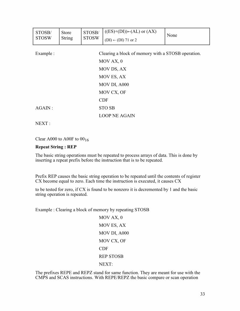
STOSB/ Store STOSB/ ((ES)+(DI))←(AL) or (AX) None
STOSW String STOSW
(DI) ← (DI) 71 or 2
Example : Clearing a block of memory with a STOSB operation.
MOV AX, 0
MOV DS, AX
MOV ES, AX
MOV DI, A000
MOV CX, OF
CDF
AGAIN : STO SB
LOOP NE AGAIN
NEXT :
Clear A000 to A00F to 0016 Repeat String : REP
The basic string operations must be repeated to process arrays of data. This is done by inserting a repeat prefix before the instruction that is to be repeated.
Prefix REP causes the basic string operation to be repeated until the contents of register CX become equal to zero. Each time the instruction is executed, it causes CX
to be tested for zero, if CX is found to be nonzero it is decremented by 1 and the basic string operation is repeated.
Example : Clearing a block of memory by repeating STOSB
MOV AX, 0
MOV ES, AX
MOV DI, A000
MOV CX, OF
CDF
REP STOSB
NEXT: The prefixes REPE and REPZ stand for same function. They are meant for use with the CMPS and SCAS instructions. With REPE/REPZ the basic compare or scan operation
33
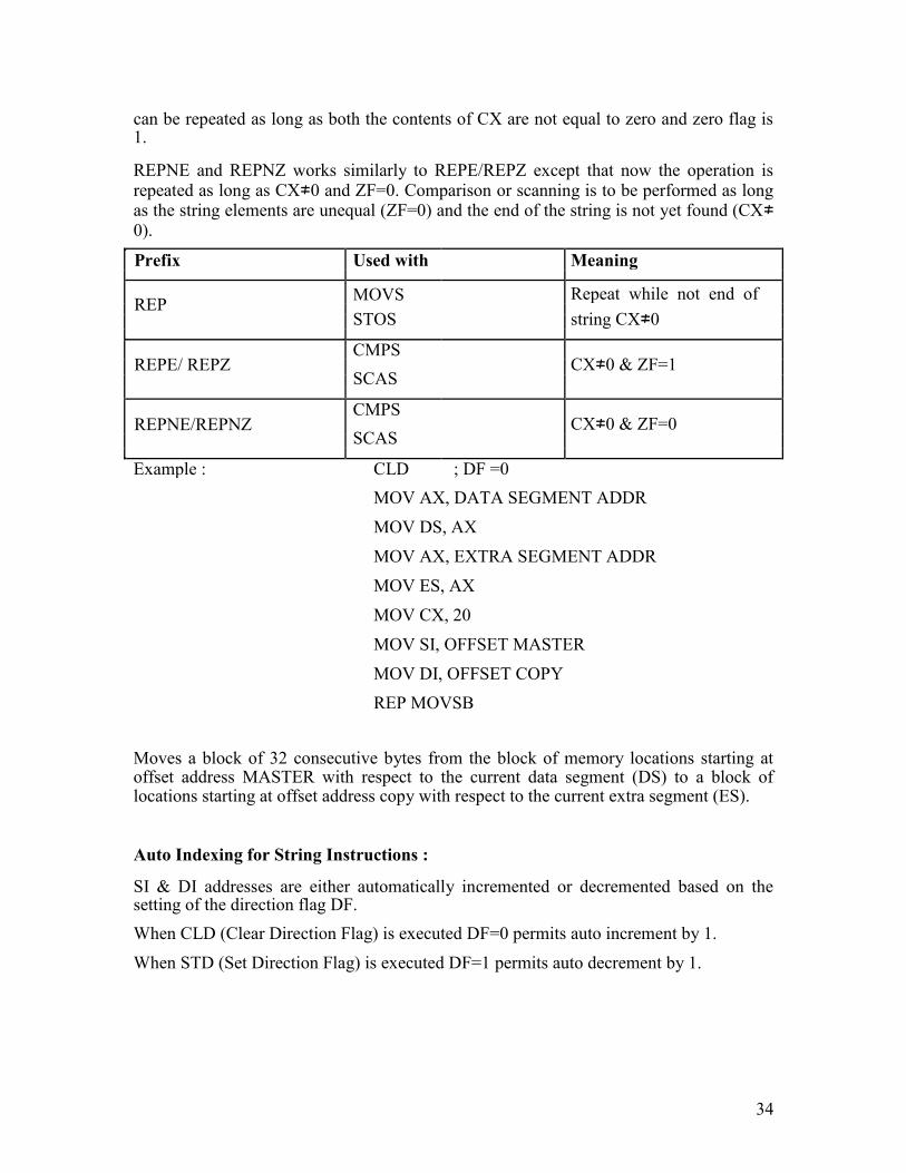
can be repeated as long as both the contents of CX are not equal to zero and zero flag is 1.
REPNE and REPNZ works similarly to REPE/REPZ except that now the operation is repeated as long as CX≠0 and ZF=0. Comparison or scanning is to be performed as long as the string elements are unequal (ZF=0) and the end of the string is not yet found (CX≠0).
Prefix Used with Meaning
REP MOVS Repeat while not end of
STOS
string CX≠0
REPE/ REPZ CMPS
CX≠0 & ZF=1
SCAS
REPNE/REPNZ CMPS
CX≠0 & ZF=0
SCAS
Example : CLD ; DF =0
MOV AX, DATA SEGMENT ADDR
MOV DS, AX
MOV AX, EXTRA SEGMENT ADDR
MOV ES, AX
MOV CX, 20
MOV SI, OFFSET MASTER
MOV DI, OFFSET COPY
REP MOVSB Moves a block of 32 consecutive bytes from the block of memory locations starting at offset address MASTER with respect to the current data segment (DS) to a block of locations starting at offset address copy with respect to the current extra segment (ES).
Auto Indexing for String Instructions : SI & DI addresses are either automatically incremented or decremented based on the setting of the direction flag DF.
When CLD (Clear Direction Flag) is executed DF=0 permits auto increment by 1.
When STD (Set Direction Flag) is executed DF=1 permits auto decrement by 1.
34

Mnemonic Meaning Format Operation Flags affected
CLD Clear DF CLD (DF) ← 0 DF
STD Set DF STD (DF) ← 1 DF
1. LDS Instruction: LDS register, memory (Loads register and DS with words from memory)
This instruction copies a word from two memory locations into the register specified in the instruction. It then copies a word from the next two memory locations into the DS register. LDS is useful for pointing SI and DS at the start of the string before using one of the string instructions. LDS affects no flags.
Example 1 :LDS BX [1234]
Copy contents of memory at displacement 1234 in DS to BL. Contents of 1235H to BH. Copy contents at displacement of 1236H and 1237H is DS to DS register.
Example 2 : LDS, SI String – Pointer
(SI) ← [String Pointer]
(DS) ← [String Pointer +2] DS, SI now points at start and desired string
2. LEA Instruction :
Load Effective Address (LEA register, source) This instruction determines the offset of the variable or memory location named as the source and puts this offset in the indicated 16 bit register.
LEA will not affect the flags.
Examples :
LEA BX, PRICES
Load BX with offset and PRICES in DS
LEA BP, SS : STACK TOP
Load BP with offset of stack-top in SS
LEA CX, [BX] [DI]
Loads CX with EA : (BX) + (DI)
35
3. LES instruction :
LES register, memory Example 1: LES BX, [789A H]
(BX) ← [789A] in DS
(ES) ← [789C] in DS Example 2 : LES DI, [BX]
(DI) ← [BX] in DS
(ES) ← [BX+2] in DS
36
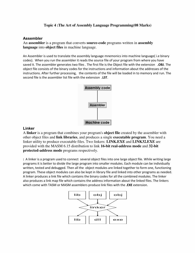
Topic 4 :The Art of Assembly Language Programming(08 Marks)
Assembler
An assembler is a program that converts source-code programs written in assembly
language into object files in machine language. An Assembler is used to translate the assembly language mnemonics into machine language( i.e binary
codes). When you run the assembler it reads the source file of your program from where you have
saved it. The assembler generates two files . The first file is the Object file with the extension .OBJ. The
object file consists of the binary codes for the instructions and information about the addresses of the
instructions. After further processing, the contents of the file will be loaded in to memory and run. The
second file is the assembler list file with the extension .LST.
Linker
A linker is a program that combines your program's object file created by the assembler with other object files and link libraries, and produces a single executable program. You need a linker utility to produce executable files. Two linkers: LINK.EXE and LINK32.EXE are provided with the MASM 6.15 distribution to link 16-bit real-address mode and 32-bit
protected-address mode programs respectively. : A linker is a program used to connect several object files into one large object file. While writing large
programs it is better to divide the large program into smaller modules. Each module can be individually
written, tested and debugged. Then all the object modules are linked together to form one, functioning
program. These object modules can also be kept in library file and linked into other programs as needed.
A linker produces a link file which contains the binary codes for all the combined modules. The linker
also produces a link map file which contains the address information about the linked files. The linkers
which come with TASM or MASM assemblers produce link files with the .EXE extension.
Locator : A locator is a program used to assign the specific addresses of where the segments of object
code are to be loaded into memory. A locator program called EXE2BIN comes with the IBM PC Disk
Operating System (DOS). EXE2BIN converts a .EXE file to a .BIN file which has physical addresses.
Debugger: A debugger is a program which allows to load your object code program into system
memory, execute the program, and troubleshoot or debug it. The debugger allows to look into the
contents of registers and memory locations after the program runs. We can also change the contents of
registers and memory locations and rerun the program. Some debuggers allows to stop the program
after each instruction so that you can check or alter memory and register contents. This is called single
step debug. A debugger also allows to set a breakpoint at any point in the program. If we insert a break
point , the debugger will run the program up to the instruction where the breakpoint is put and then
stop the execution.
Editor
An Editor is a program which allows us to create a file containing the assembly language statements for
the program. Examples of some editors are PC write Wordstar. As we type the program the editor
stores the ACSII codes for the letters and numbers in successive RAM locations. If any typing mistake is
done editor will alert us to correct it. If we leave out a program statement an editor will let you move
everything down and insert a line. After typing all the program we have to save the program for a hard
disk. This we call it as source file. The next step is to process the source file with an assembler. While
using TASM or MASM we should give a file name and extension .ASM.
Ex: Sample. asm
Emulator: An emulator is a mixture of hard ware and software. It is usually used to test and debug the
hardware and software of an external system such as the prototype of a microprocessor based
instrument.
ASSEMBLER DIRECTIVES AND OPERATORS
ASSEMBLER DIRECTIVES :
Assembler directives are the directions to the assembler which indicate how an operand or
section of the program is to be processed. These are also called pseudo operations which are not
executable by the microprocessor. The various directives are explained below.
1. ASSUME : The ASSUME directive is used to inform the assembler the name of the logical segment it
should use for a specified segment.
Ex: ASSUME DS: DATA tells the assembler that for any program instruction which refers to the data
segment ,it should use the logical segment called DATA.
2.DB -Define byte. It is used to declare a byte variable or set aside one or more storage locations of type
byte in memory.
For example, CURRENT_VALUE DB 36H tells the assembler to reserve 1 byte of memory for a variable
named CURRENT_ VALUE and to put the value 36 H in that memory location when the program is
loaded into RAM .
3. DW -Define word. It tells the assembler to define a variable of type word or to reserve storage
locations of type word in memory.
4. DD(define double word) :This directive is used to declare a variable of type double word or restore
memory locations which can be accessed as type double word.
5.DQ (define quadword) :This directive is used to tell the assembler to declare a variable 4 words in
length or to reserve 4 words of storage in memory .
6.DT (define ten bytes):It is used to inform the assembler to define a variable which is 10 bytes in length
or to reserve 10 bytes of storage in memory.
7. EQU –Equate It is used to give a name to some value or symbol. Every time the assembler finds the
given name in the program, it will replace the name with the value or symbol we have equated with that
name
8.ORG -Originate : The ORG statement changes the starting offset address of the data.
It allows to set the location counter to a desired value at any point in the program.For example the
statement ORG 3000H tells the assembler to set the location counter to 3000H.
9 .PROC- Procedure: It is used to identify the start of a procedure. Or subroutine.
10. END- End program .This directive indicates the assembler that this is the end of the program
module.The assembler ignores any statements after an END directive.
11. ENDP- End procedure: It indicates the end of the procedure (subroutine) to the assembler.
12.ENDS-End Segment: This directive is used with the name of the segment to indicate the end of that
logical segment.
Ex: CODE SEGMENT : Start of logical segment containing code
CODE ENDS : End of the segment named CODE.
SEGMENT The SEGMENT directive is used to indicate the start of a logical segment. Preceding the SEGMENT directive is the name you want to give the segment. For example, the statement CODE SEGMENT indicates to the assembler the start of a logical segment called CODE. The SEGMENT and ENDS directive are used to “bracket” a logical segment containing code of data. Additional terms are often added to a SEGMENT directive statement to indicate some special way in which we want the assembler to treat the segment. The statement CODE SEGMENT WORD tells the assembler that we want the content of this segment located on the next available word (even address) when segments ate combined and given absolute addresses. Without this WORD addition, the segment will be located on the next available paragraph (16-byte) address, which might waste as much as 15 bytes of memory. The statement CODE SEGMENT PUBLIC tells the assembler that the segment may be put together with other segments named CODE from other assembly modules when the modules are linked together. ENDS (END SEGMENT) This directive is used with the name of a segment to indicate the end of that logical segment. CODE SEGMENT Start of logical segment containing code instruction statements CODE ENDS End of segment named CODE
END (END PROCEDURE) The END directive is put after the last statement of a program to tell the assembler that this is the end of the program module. The assembler will ignore any statements after an END directive, so you should make sure to use only one END directive at the very end of your program module. A carriage return is required after the END directive.
ASSUME The ASSUME directive is used tell the assembler the name of the logical segment it should use for a specified segment. The statement ASSUME CS: CODE, for example, tells the assembler that the instructions for a program are in a logical segment named CODE. The statement ASSUME DS: DATA tells the assembler that for any program instruction, which refers to the data segment, it should use the logical segment called DATA.
DB (DEFINE BYTE) The DB directive is used to declare a byte type variable, or a set aside one or more storage locations of type byte in memory. PRICES DB 49H, 98H, 29H Declare array of 3 bytes named PRICE and initialize them with specified values. NAMES DB “THOMAS” Declare array of 6 bytes and initialize with ASCII codes for the letters in THOMAS.

TEMP DB 100 DUP (?) Set aside 100 bytes of storage in memory and give it the name TEMP. But leave the 100 bytes un-initialized. PRESSURE DB 20H DUP (0) Set aside 20H bytes of storage in memory, give it the name PRESSURE and put 0 in all 20H locations. DD (DEFINE DOUBLE WORD) The DD directive is used to declare a variable of type double word or to reserve memory locations, which can be accessed as type double word. The statement ARRAY DD 25629261H, for example, will define a double word named ARRAY and initialize the double word with the specified value when the program is loaded into memory to be run. The low word, 9261H, will be put in memory at a lower address than the high word.
DQ (DEFINE QUADWORD) The DQ directive is used to tell the assembler to declare a variable 4 words in length or to reserve 4 words of storage in memory. The statement BIG_NUMBER DQ 243598740192A92BH, for example, will declare a variable named BIG_NUMBER and initialize the 4 words set aside with the specified number when the program is loaded into memory to be run.
DT (DEFINE TEN BYTES) The DT directive is used to tell the assembler to declare a variable, which is 10 bytes in length or to reserve 10 bytes of storage in memory. The statement PACKED_BCD DT 11223344556677889900 will declare an array named PACKED_BCD, which is 10 bytes in length. It will initialize the 10 bytes with the values 11, 22, 33, 44, 55, 66, 77, 88, 99, and 00 when the program is loaded into memory to be run. The statement RESULT DT 20H DUP (0) will declare an array of 20H blocks of 10 bytes each and initialize all 320 bytes to 00 when the program is loaded into memory to be run.
DW (DEFINE WORD) The DW directive is used to tell the assembler to define a variable of type word or to reserve storage locations of type word in memory. The statement MULTIPLIER DW 437AH, for example, declares a variable of type word named MULTIPLIER, and initialized with the value 437AH when the program is loaded into memory to be run. WORDS DW 1234H, 3456H Declare an array of 2 words and initialize them with the specified values. STORAGE DW 100 DUP (0) Reserve an array of 100 words of memory and initialize all 100 words with 0000. Array is named as STORAGE. STORAGE DW 100 DUP (?) Reserve 100 word of storage in memory and give it the name STORAGE, but leave the words un-initialized.
EQU (EQUATE) EQU is used to give a name to some value or symbol. Each time the assembler finds the given name in the program, it replaces the name with the value or symbol you equated with that name. Suppose, for example, you write the statement FACTOR EQU 03H at the start of your program, and later in the program you write the instruction statement ADD AL, FACTOR. When the assembler codes this instruction statement, it will code it as if you had written the instruction ADD AL, 03H. CONTROL EQU 11000110 B Replacement MOV AL, CONTROL Assignment DECIMAL_ADJUST EQU DAA Create clearer mnemonic for DAA ADD AL, BL Add BCD numbers DECIMAL_ADJUST Keep result in BCD format LENGTH
LENGTH is an operator, which tells the assembler to determine the number of elements in some named data item, such as a string or an array. When the assembler reads the statement MOV CX, LENGTH STRING1, for example, will determine the number of elements in STRING1 and load it into CX. If the string was declared as a string of bytes, LENGTH will produce the number of bytes in the string. If the string was declared as a word string, LENGTH will produce the number of words in the string. OFFSET OFFSET is an operator, which tells the assembler to determine the offset or displacement of a named data item (variable), a procedure from the start of the segment, which contains it. When the assembler reads the statement MOV BX, OFFSET PRICES, for example, it will determine the offset of the variable PRICES from the start of the segment in which PRICES is defined and will load this value into BX. PTR (POINTER) The PTR operator is used to assign a specific type to a variable or a label. It is necessary to do this in any instruction where the type of the operand is not clear. When the assembler reads the instruction INC [BX], for example, it will not know whether to increment the byte pointed to by BX. We use the PTR operator to clarify how we want the assembler to code the instruction. The statement INC BYTE PTR [BX] tells the assembler that we want to increment the byte pointed to by BX. The statement INC WORD PTR [BX] tells the assembler that we want to increment the word pointed to by BX. The PTR operator assigns the type specified before PTR to the variable specified after PTR. We can also use the PTR operator to clarify our intentions when we use indirect Jump instructions. The statement JMP [BX], for example, does not tell the assembler whether to code the instruction for a near jump. If we want to do a near jump, we write the instruction as JMP WORD PTR [BX]. If we want to do a far jump, we write the instruction as JMP DWORD PTR [BX].
FAR PTR: This directive indicates the assembler that the label following FAR PTR is not available within the same
segment and the address of the bit is of 32 bits i.e. 2 bytes offset followed by 2 bytes.
NEAR PTR: This directive indicates that the label following NEAR PTR is in the same segment and need only 16 bit
i.e. 2 byte offset to address it. A NEAR PTR label is considered as default if a label is not preceded by NEAR PTR or
FAR PTR.
EVEN (ALIGN ON EVEN MEMORY ADDRESS) As an assembler assembles a section of data declaration or instruction statements, it uses a location counter to keep track of how many bytes it is from the start of a segment at any time. The EVEN directive tells the assembler to increment the location counter to the next even address, if it is not already at an even address. A NOP instruction will be inserted in the location incremented over.
DATA SEGMENT SALES DB 9 DUP (?) Location counter will point to 0009 after this instruction. EVEN Increment location counter to 000AH INVENTORY DW 100 DUP (0) Array of 100 words starting on even address for quicker read DATA ENDS PROC (PROCEDURE) The PROC directive is used to identify the start of a procedure. The PROC directive follows a name you give the procedure. After the PROC directive, the term near or the term far is used to specify the type of
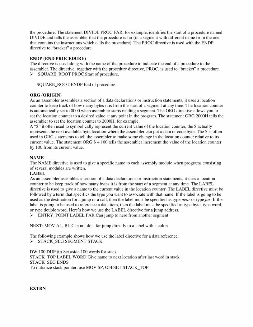
the procedure. The statement DIVIDE PROC FAR, for example, identifies the start of a procedure named DIVIDE and tells the assembler that the procedure is far (in a segment with different name from the one that contains the instructions which calls the procedure). The PROC directive is used with the ENDP directive to “bracket” a procedure. ENDP (END PROCEDURE) The directive is used along with the name of the procedure to indicate the end of a procedure to the assembler. The directive, together with the procedure directive, PROC, is used to “bracket” a procedure. SQUARE_ROOT PROC Start of procedure. SQUARE_ROOT ENDP End of procedure.
ORG (ORIGIN) As an assembler assembles a section of a data declarations or instruction statements, it uses a location counter to keep track of how many bytes it is from the start of a segment at any time. The location counter is automatically set to 0000 when assembler starts reading a segment. The ORG directive allows you to set the location counter to a desired value at any point in the program. The statement ORG 2000H tells the assembler to set the location counter to 2000H, for example. A “$” it often used to symbolically represent the current value of the location counter, the $ actually represents the next available byte location where the assembler can put a data or code byte. The $ is often used in ORG statements to tell the assembler to make some change in the location counter relative to its current value. The statement ORG $ + 100 tells the assembler increment the value of the location counter by 100 from its current value. NAME The NAME directive is used to give a specific name to each assembly module when programs consisting of several modules are written. LABEL As an assembler assembles a section of a data declarations or instruction statements, it uses a location counter to be keep track of how many bytes it is from the start of a segment at any time. The LABEL directive is used to give a name to the current value in the location counter. The LABEL directive must be followed by a term that specifics the type you want to associate with that name. If the label is going to be used as the destination for a jump or a call, then the label must be specified as type near or type far. If the label is going to be used to reference a data item, then the label must be specified as type byte, type word, or type double word. Here’s how we use the LABEL directive for a jump address. ENTRY_POINT LABEL FAR Can jump to here from another segment NEXT: MOV AL, BL Can not do a far jump directly to a label with a colon The following example shows how we use the label directive for a data reference. STACK_SEG SEGMENT STACK DW 100 DUP (0) Set aside 100 words for stack STACK_TOP LABEL WORD Give name to next location after last word in stack STACK_SEG ENDS To initialize stack pointer, use MOV SP, OFFSET STACK_TOP.
EXTRN
The EXTRN directive is used to tell the assembler that the name or labels following the directive are in some other assembly module. For example, if you want to call a procedure, which in a program module assembled at a different time from that which contains the CALL instruction, you must tell the assembler that the procedure is external. The assembler will then put this information in the object code file so that the linker can connect the two modules together. For a reference to externally named variable, you must specify the type of the variable, as in the statement EXTRN DIVISOR: WORD. The statement EXTRN DIVIDE: FAR tells the assembler that DIVIDE is a label of type FAR in another assembler module. Name or labels referred to as external in one module must be declared public with the PUBLIC directive in the module in which they are defined. PROCEDURE SEGMENT EXTRN DIVIDE: FAR Found in segment PROCEDURES PROCEDURE ENDS PUBLIC Large program are usually written as several separate modules. Each module is individually assembled, tested, and debugged. When all the modules are working correctly, their object code files are linked together to form the complete program. In order for the modules to link together correctly, any variable name or label referred to in other modules must be declared PUBLIC in the module in which it is defined. The PUBLIC directive is used to tell the assembler that a specified name or label will be accessed from other modules. An example is the statement PUBLIC DIVISOR, DIVIDEND, which makes the two variables DIVISOR and DIVIDEND available to other assembly modules.
SHORT The SHORT operator is used to tell the assembler that only a 1 byte displacement is needed to code a jump instruction in the program. The destination must in the range of –128 bytes to +127 bytes from the address of the instruction after the jump. The statement JMP SHORT NEARBY_LABEL is an example of the use of SHORT.
TYPE The TYPE operator tells the assembler to determine the type of a specified variable. The assembler actually determines the number of bytes in the type of the variable. For a byte-type variable, the assembler will give a value of 1, for a word-type variable, the assembler will give a value of 2, and for a double word-type variable, it will give a value of 4. It can be used in instruction such as ADD BX, TYPE-WORD-ARRAY, where we want to increment BX to point to the next word in an array of words GLOBAL (DECLARE SYMBOLS AS PUBLIC OR EXTRN) The GLOBAL directive can be used in place of a PUBLIC directive or in place of an EXTRN directive. For a name or symbol defined in the current assembly module, the GLOBAL directive is used to make the symbol available to other modules. The statement GLOBAL DIVISOR, for example, makes the variable DIVISOR public so that it can be accessed from other assembly modules.
INCLUDE (INCLUDE SOURCE CODE FROM FILE) This directive is used to tell the assembler to insert a block of source code from the named file into the current source module.

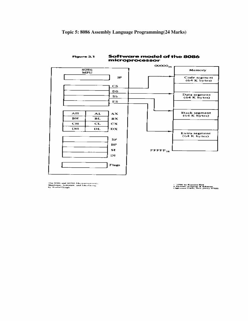
Topic 5: 8086 Assembly Language Programming(24 Marks)

Add two 8bit numbers
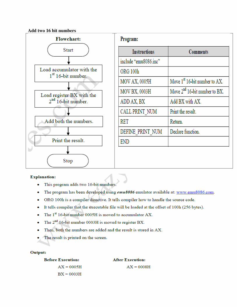
Add two 16 bit numbers
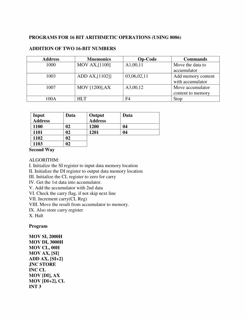
PROGRAMS FOR 16 BIT ARITHMETIC OPERATIONS (USING 8086)
ADDITION OF TWO 16-BIT NUMBERS
Address Mnemonics Op-Code Commands
1000 MOV AX,[1100] A1,00,11 Move the data to accumulator
1003 ADD AX,[1102]] 03,06,02,11 Add memory content with accumulator
1007 MOV [1200],AX A3,00,12 Move accumulator content to memory
100A HLT F4 Stop
Input
Address
Data Output
Address
Data
1100 02 1200 04
1101 02 1201 04
1102 02
1103 02
Second Way
ALGORITHM: I. Initialize the SI register to input data memory location II. Initialize the DI register to output data memory location III. Initialize the CL register to zero for carry IV. Get the 1st data into accumulator. V. Add the accumulator with 2nd data VI. Check the carry flag, if not skip next line VII. Increment carry(CL Reg) VIII. Move the result from accumulator to memory. IX. Also store carry register X. Halt
Program
MOV SI, 2000H
MOV DI, 3000H
MOV CL, 00H
MOV AX, [SI]
ADD AX, [SI+2]
JNC STORE
INC CL
MOV [DI], AX
MOV [DI+2], CL
INT 3
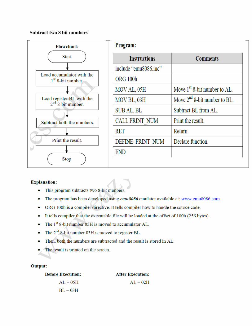
Subtract two 8 bit numbers

Subtract two 16bit numbers
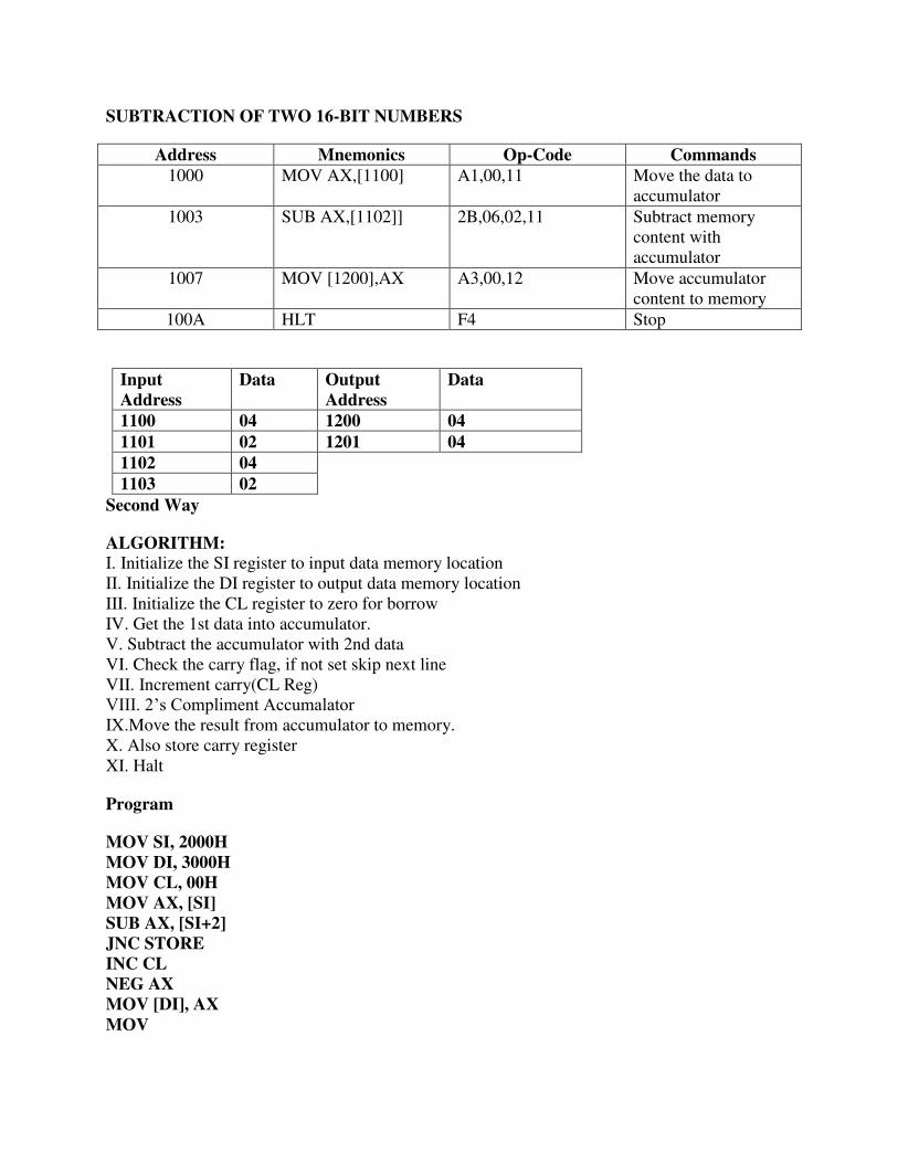
SUBTRACTION OF TWO 16-BIT NUMBERS
Address Mnemonics Op-Code Commands
1000 MOV AX,[1100] A1,00,11 Move the data to accumulator
1003 SUB AX,[1102]] 2B,06,02,11 Subtract memory content with accumulator
1007 MOV [1200],AX A3,00,12 Move accumulator content to memory
100A HLT F4 Stop
Input
Address
Data Output
Address
Data
1100 04 1200 04
1101 02 1201 04
1102 04
1103 02
Second Way
ALGORITHM:
I. Initialize the SI register to input data memory location II. Initialize the DI register to output data memory location III. Initialize the CL register to zero for borrow IV. Get the 1st data into accumulator. V. Subtract the accumulator with 2nd data VI. Check the carry flag, if not set skip next line VII. Increment carry(CL Reg) VIII. 2’s Compliment Accumalator IX.Move the result from accumulator to memory. X. Also store carry register XI. Halt
Program
MOV SI, 2000H
MOV DI, 3000H
MOV CL, 00H
MOV AX, [SI]
SUB AX, [SI+2]
JNC STORE
INC CL
NEG AX
MOV [DI], AX
MOV
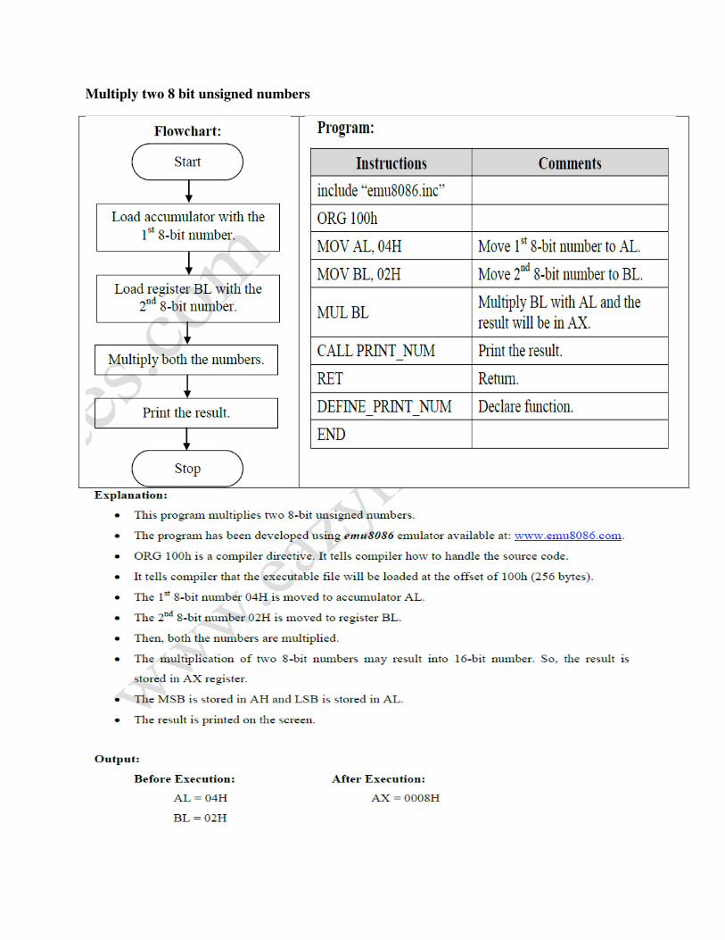
Multiply two 8 bit unsigned numbers
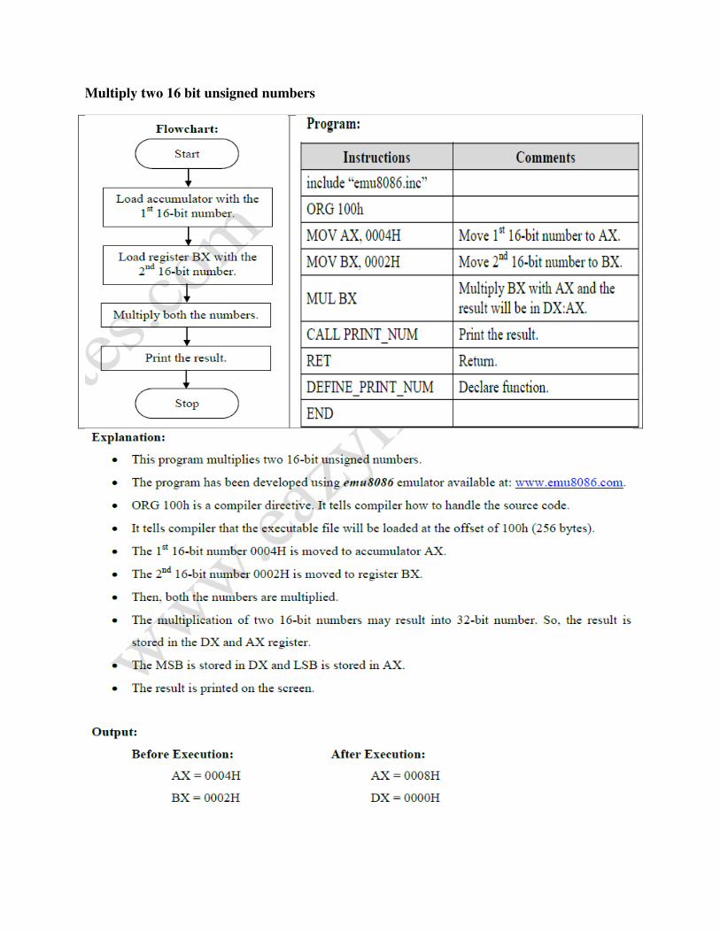
Multiply two 16 bit unsigned numbers
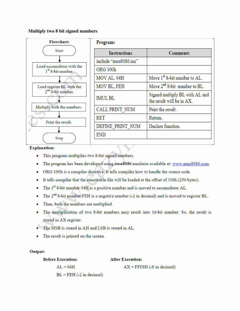
Multiply two 8 bit signed numbers
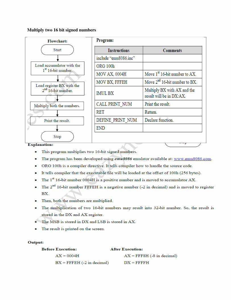
Multiply two 16 bit signed numbers
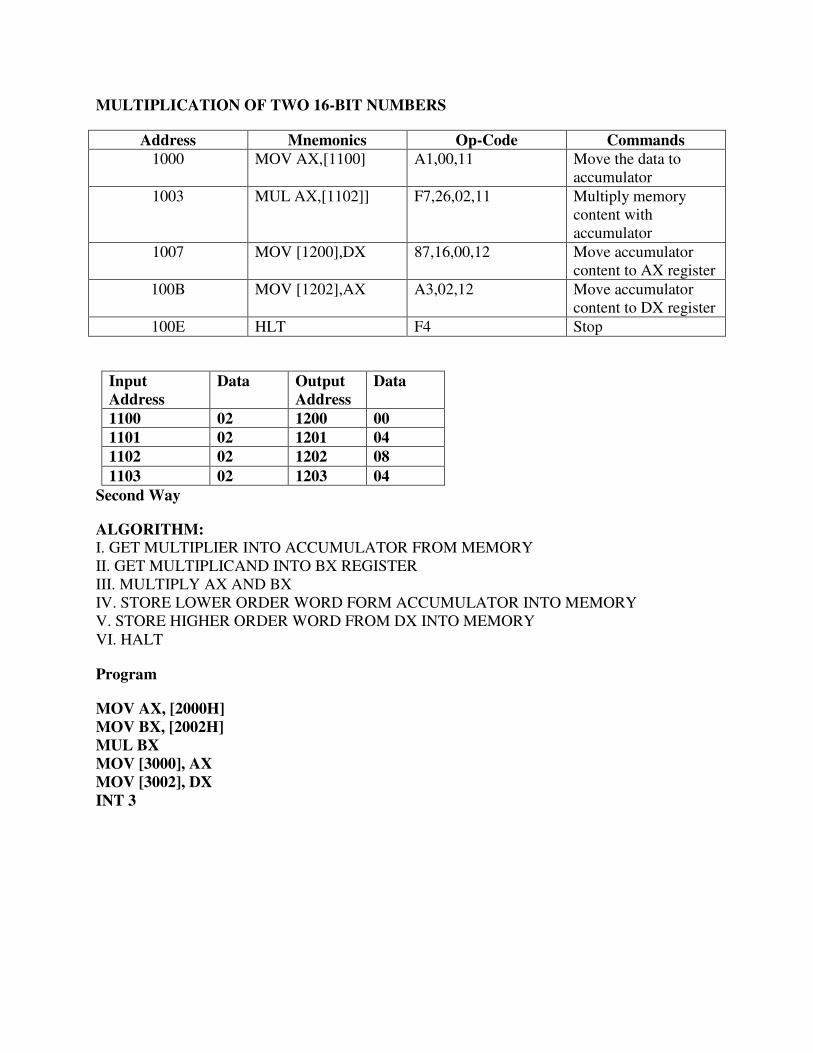
MULTIPLICATION OF TWO 16-BIT NUMBERS
Address Mnemonics Op-Code Commands
1000 MOV AX,[1100] A1,00,11 Move the data to accumulator
1003 MUL AX,[1102]] F7,26,02,11 Multiply memory content with accumulator
1007 MOV [1200],DX 87,16,00,12 Move accumulator content to AX register
100B MOV [1202],AX A3,02,12 Move accumulator content to DX register
100E HLT F4 Stop
Input
Address
Data Output
Address
Data
1100 02 1200 00
1101 02 1201 04
1102 02 1202 08
1103 02 1203 04
Second Way
ALGORITHM:
I. GET MULTIPLIER INTO ACCUMULATOR FROM MEMORY II. GET MULTIPLICAND INTO BX REGISTER III. MULTIPLY AX AND BX IV. STORE LOWER ORDER WORD FORM ACCUMULATOR INTO MEMORY V. STORE HIGHER ORDER WORD FROM DX INTO MEMORY VI. HALT
Program
MOV AX, [2000H]
MOV BX, [2002H]
MUL BX
MOV [3000], AX
MOV [3002], DX
INT 3
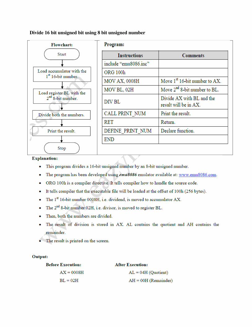
Divide 16 bit unsigned bit using 8 bit unsigned number

Divide 16 bit signed bit using 8 bit signed number

DIVISION OF TWO 16-BIT NUMBERS
Address Mnemonics Op-Code Commands
1000 MOV AX,[1100] A1,00,11 Move the data to accumulator
1003 DIV AX,[1102]] F7,26,02,11 Divide memory content with accumulator
1007 MOV [1200],DX 87,16,00,12 Move accumulator content to AX register
100B MOV [1202],AX A3,02,12 Move accumulator content to DX register
100E HLT F4 Stop
Input
Address
Data Output
Address
Data
1100 04 1200 02
1101 04 1201 02
1102 02 1202 00
1103 02 1203 00
Second Way
ALGORITHM:
I. GET DIVIDEND INTO ACCUMULATOR FROM MEMORY II. GET DIVISOR INTO BX REGISTER III. DIVIDE AX BY BX IV. STORE QUOTIENT FORM ACCUMULATOR INTO MEMORY V. STORE REMAINDER FROM DX INTO MEMORY VI. HALT
Program
MOV AX, [2000H]
MOV BX, [2002H]
DIV BX
MOV [3000], AX
MOV [3002], DX
INT 3
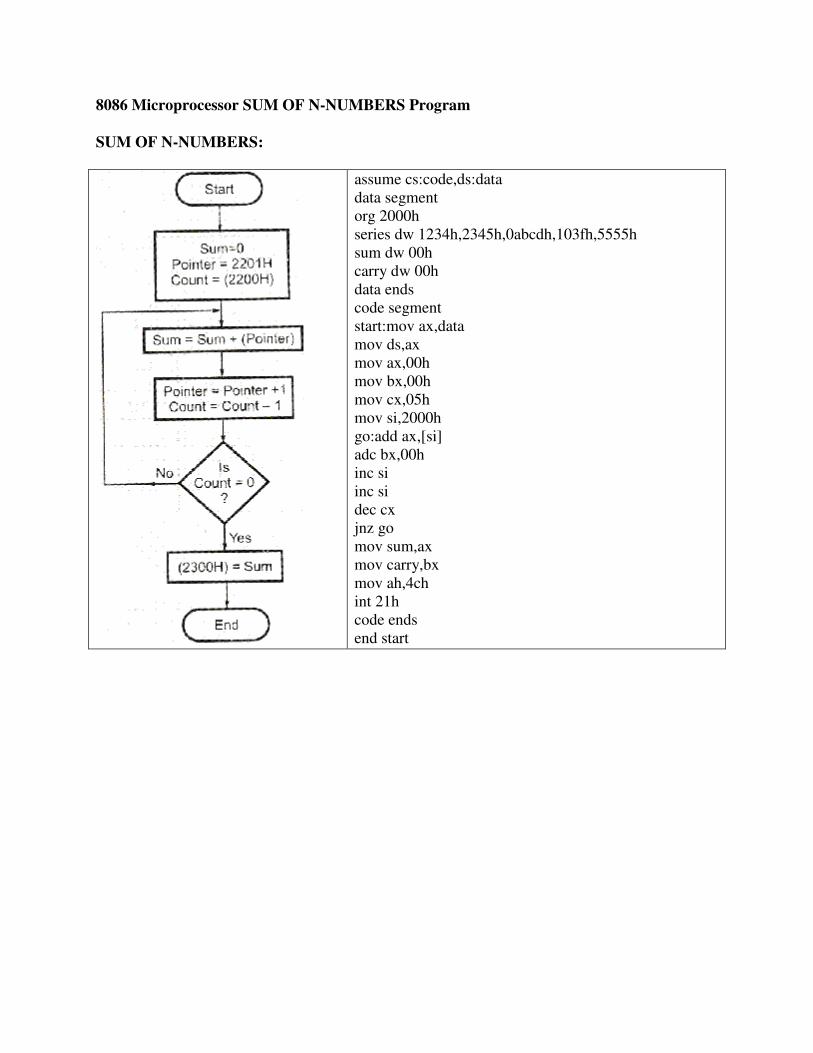
8086 Microprocessor SUM OF N-NUMBERS Program
SUM OF N-NUMBERS:
assume cs:code,ds:data data segment org 2000h series dw 1234h,2345h,0abcdh,103fh,5555h sum dw 00h carry dw 00h data ends code segment start:mov ax,data mov ds,ax mov ax,00h mov bx,00h mov cx,05h mov si,2000h go:add ax,[si] adc bx,00h inc si inc si dec cx jnz go mov sum,ax mov carry,bx mov ah,4ch int 21h code ends end start
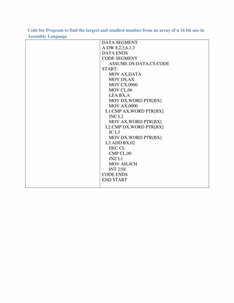
Code for Program to find the largest and smallest number from an array of n 16 bit nos in
Assembly Language
DATA SEGMENT A DW 8,2,5,6,1,3 DATA ENDS CODE SEGMENT ASSUME DS:DATA,CS:CODE START: MOV AX,DATA MOV DS,AX MOV CX,0000 MOV CL,06 LEA BX,A MOV DX,WORD PTR[BX] MOV AX,0000 L1:CMP AX,WORD PTR[BX] JNC L2 MOV AX,WORD PTR[BX] L2:CMP DX,WORD PTR[BX] JC L3 MOV DX,WORD PTR[BX] L3:ADD BX,02 DEC CL CMP CL,00 JNZ L1 MOV AH,4CH INT 21H CODE ENDS END START
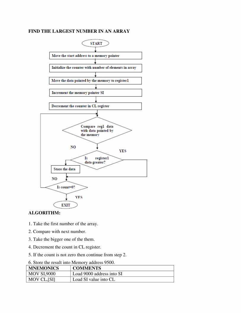
FIND THE LARGEST NUMBER IN AN ARRAY
ALGORITHM:
1. Take the first number of the array.
2. Compare with next number.
3. Take the bigger one of the them.
4. Decrement the count in CL register.
5. If the count is not zero then continue from step 2.
6. Store the result into Memory address 9500.
MNEMONICS COMMENTS MOV SI,9000 Load 9000 address into SI
MOV CL,[SI] Load SI value into CL
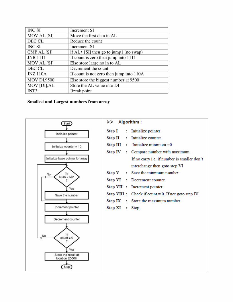
INC SI Increment SI
MOV AL,[SI] Move the first data in AL
DEC CL Reduce the count
INC SI Increment SI
CMP AL,[SI] if AL> [SI] then go to jump1 (no swap)
JNB 1111 If count is zero then jump into 1111
MOV AL,[SI] Else store large no in to AL
DEC CL Decrement the count
JNZ 110A If count is not zero then jump into 110A
MOV DI,9500 Else store the biggest number at 9500
MOV [DI],AL Store the AL value into DI
INT3 Break point
Smallest and Largest numbers from array
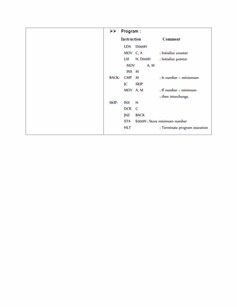
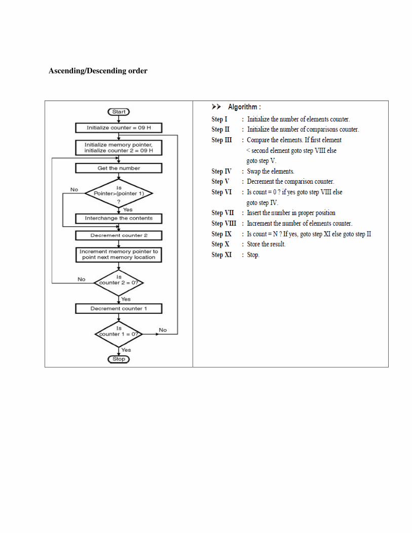
Ascending/Descending order
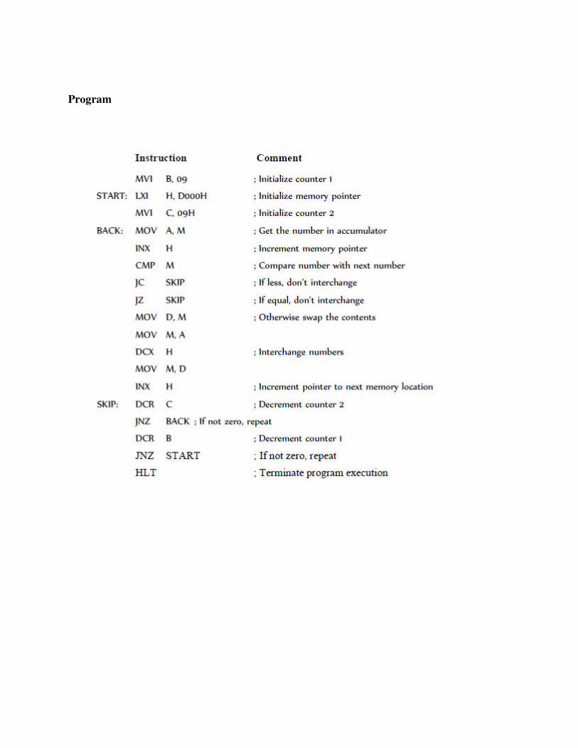
Program
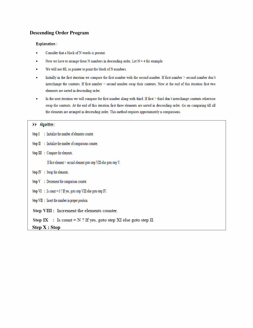
Descending Order Program
Step X : Stop

Algorithm:
i. Load SI reg with pointer to array ii. Load array length to CL & CH for two counters (CL for repetitions & CH for comparisons) iii. REPEAT : Get an element into accumulator iv. NEXT: Compare with next element v. Check carry flag, if set goto SKIP vi. Swap elements of array vii. SKIP: Decrement CH and if not zero go to NEXT viii. Decrement CL , if not zero go to REPEAT ix. Halt
Program
Label Mnemonics
REPEAT:
MOV SI, 1500H
MOV CL, [SI]
DEC CL
MOV SI, 1500H
MOV CH, [SI]
DEC CH
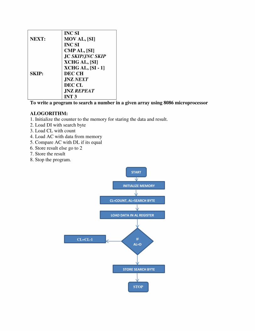
NEXT:
SKIP:
INC SI
MOV AL, [SI]
INC SI
CMP AL, [SI]
JC SKIP/JNC SKIP
XCHG AL, [SI]
XCHG AL, [SI - 1]
DEC CH
JNZ NEXT
DEC CL
JNZ REPEAT
INT 3
To write a program to search a number in a given array using 8086 microprocessor
ALOGORITHM:
1. Initialize the counter to the memory for staring the data and result. 2. Load DI with search byte 3. Load CL with count 4. Load AC with data from memory 5. Compare AC with DL if its equal 6. Store result else go to 2 7. Store the result 8. Stop the program.
START
INITIALIZE MEMORY
CL=COUNT, AL=SEARCH BYTE
LOAD DATA IN AL REGISTER
IF
AL=D
STORE SEARCH BYTE
STOP
CL=CL-1
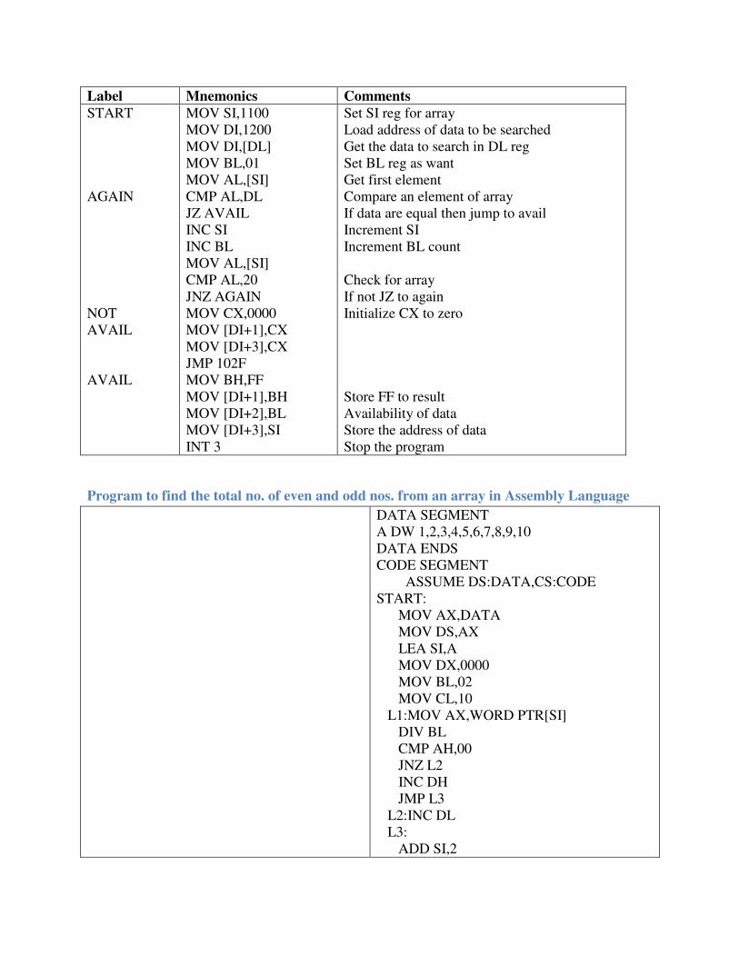
Label Mnemonics Comments
START AGAIN NOT AVAIL AVAIL
MOV SI,1100 MOV DI,1200 MOV DI,[DL] MOV BL,01 MOV AL,[SI] CMP AL,DL JZ AVAIL INC SI INC BL MOV AL,[SI] CMP AL,20 JNZ AGAIN MOV CX,0000 MOV [DI+1],CX MOV [DI+3],CX JMP 102F MOV BH,FF MOV [DI+1],BH MOV [DI+2],BL MOV [DI+3],SI INT 3
Set SI reg for array Load address of data to be searched Get the data to search in DL reg Set BL reg as want Get first element Compare an element of array If data are equal then jump to avail Increment SI Increment BL count Check for array If not JZ to again Initialize CX to zero Store FF to result Availability of data Store the address of data Stop the program
Program to find the total no. of even and odd nos. from an array in Assembly Language
DATA SEGMENT A DW 1,2,3,4,5,6,7,8,9,10 DATA ENDS CODE SEGMENT ASSUME DS:DATA,CS:CODE START: MOV AX,DATA MOV DS,AX LEA SI,A MOV DX,0000 MOV BL,02 MOV CL,10 L1:MOV AX,WORD PTR[SI] DIV BL CMP AH,00 JNZ L2 INC DH JMP L3 L2:INC DL L3: ADD SI,2

DEC CL CMP CL,00 JNZ L1 MOV AH,4CH INT 21H CODE ENDS END START
Finding Positive and Negative Numbers in array
.MODEL SMALL
.DATA cr equ 0dh lf equ 0ah LIST dW 2579H, 0A500H, 0C009H,0159H,0B900H COUNT EQU 05H .CODE mov ax,@data mov ds,ax XOR BX,BX XOR DX,DX MOV CL,COUNT MOV SI, OFFSET LIST AGAIN: MOV AX,[SI] SHL AX,01 JC NEGAT INC BX JMP NEXT NEGAT: INC DX NEXT: ADD SI,02 DEC CL JNZ AGAIN MOV ah,4ch INT 21h end
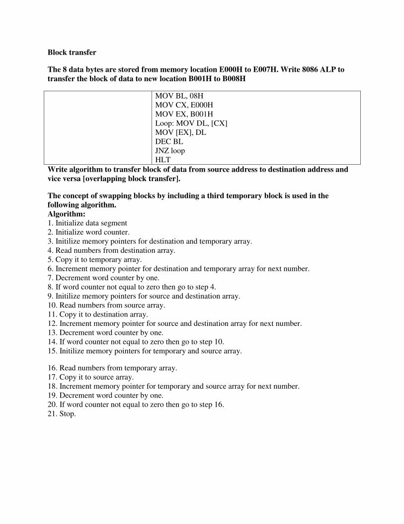
Block transfer
The 8 data bytes are stored from memory location E000H to E007H. Write 8086 ALP to
transfer the block of data to new location B001H to B008H
MOV BL, 08H MOV CX, E000H MOV EX, B001H Loop: MOV DL, [CX] MOV [EX], DL DEC BL JNZ loop HLT
Write algorithm to transfer block of data from source address to destination address and
vice versa [overlapping block transfer].
The concept of swapping blocks by including a third temporary block is used in the
following algorithm.
Algorithm:
1. Initialize data segment 2. Initialize word counter. 3. Initilize memory pointers for destination and temporary array. 4. Read numbers from destination array. 5. Copy it to temporary array. 6. Increment memory pointer for destination and temporary array for next number. 7. Decrement word counter by one. 8. If word counter not equal to zero then go to step 4. 9. Initilize memory pointers for source and destination array. 10. Read numbers from source array. 11. Copy it to destination array. 12. Increment memory pointer for source and destination array for next number. 13. Decrement word counter by one. 14. If word counter not equal to zero then go to step 10. 15. Initilize memory pointers for temporary and source array.
16. Read numbers from temporary array. 17. Copy it to source array. 18. Increment memory pointer for temporary and source array for next number. 19. Decrement word counter by one. 20. If word counter not equal to zero then go to step 16. 21. Stop.
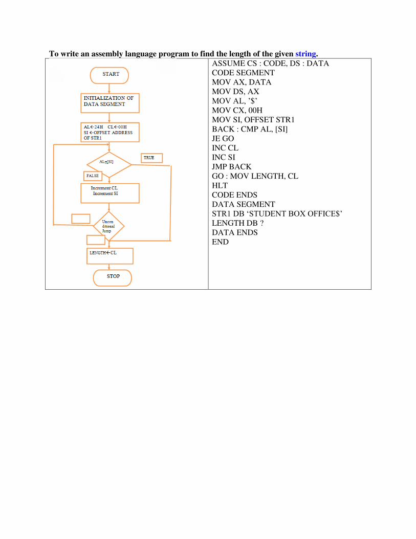
To write an assembly language program to find the length of the given string.
ASSUME CS : CODE, DS : DATA CODE SEGMENT MOV AX, DATA MOV DS, AX MOV AL, ’$’ MOV CX, 00H MOV SI, OFFSET STR1 BACK : CMP AL, [SI] JE GO INC CL INC SI JMP BACK GO : MOV LENGTH, CL HLT CODE ENDS DATA SEGMENT STR1 DB ‘STUDENT BOX OFFICE$’ LENGTH DB ? DATA ENDS END
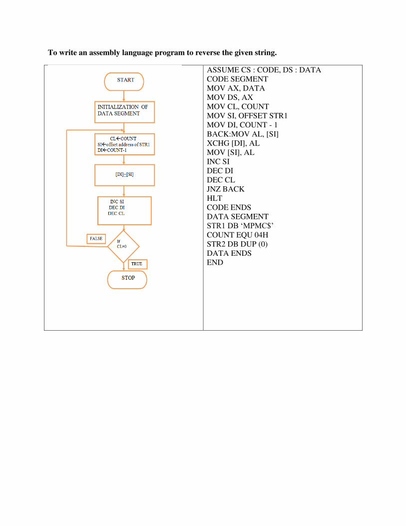
To write an assembly language program to reverse the given string.
ASSUME CS : CODE, DS : DATA CODE SEGMENT MOV AX, DATA MOV DS, AX MOV CL, COUNT MOV SI, OFFSET STR1 MOV DI, COUNT - 1 BACK:MOV AL, [SI] XCHG [DI], AL MOV [SI], AL INC SI DEC DI DEC CL JNZ BACK HLT CODE ENDS DATA SEGMENT STR1 DB ‘MPMC$’ COUNT EQU 04H STR2 DB DUP (0) DATA ENDS END
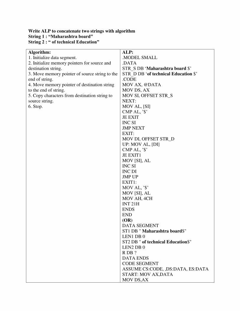
Write ALP to concatenate two strings with algorithm
String 1 : “Maharashtra board”
String 2 : “ of technical Education”
Algorithm:
1. Initialize data segment. 2. Initialize memory pointers for source and destination string. 3. Move memory pointer of source string to the end of string. 4. Move memory pointer of destination string to the end of string. 5. Copy characters from destination string to source string. 6. Stop.
ALP:
.MODEL SMALL
.DATA STR_S DB ‘Maharashtra board $’ STR_D DB ‘of technical Education $’ .CODE MOV AX, @DATA MOV DS, AX MOV SI, OFFSET STR_S NEXT: MOV AL, [SI] CMP AL, ’$’ JE EXIT INC SI JMP NEXT EXIT: MOV DI, OFFSET STR_D UP: MOV AL, [DI] CMP AL, ’$’ JE EXIT1 MOV [SI], AL INC SI INC DI JMP UP EXIT1: MOV AL, ’$’ MOV [SI], AL MOV AH, 4CH INT 21H ENDS END (OR)
DATA SEGMENT ST1 DB " Maharashtra board$" LEN1 DB 0 ST2 DB " of technical Education$" LEN2 DB 0 R DB ? DATA ENDS CODE SEGMENT ASSUME CS:CODE, ,DS:DATA, ES:DATA START: MOV AX,DATA MOV DS,AX
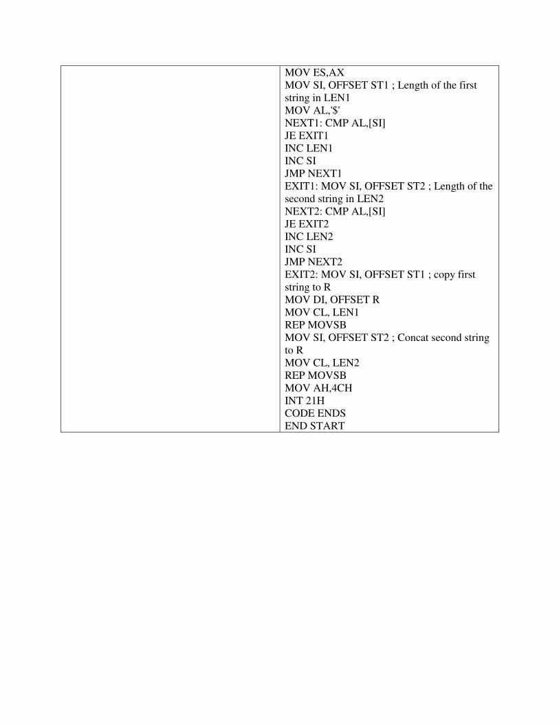
MOV ES,AX MOV SI, OFFSET ST1 ; Length of the first string in LEN1 MOV AL,'$' NEXT1: CMP AL,[SI] JE EXIT1 INC LEN1 INC SI JMP NEXT1 EXIT1: MOV SI, OFFSET ST2 ; Length of the second string in LEN2 NEXT2: CMP AL,[SI] JE EXIT2 INC LEN2 INC SI JMP NEXT2 EXIT2: MOV SI, OFFSET ST1 ; copy first string to R MOV DI, OFFSET R MOV CL, LEN1 REP MOVSB MOV SI, OFFSET ST2 ; Concat second string to R MOV CL, LEN2 REP MOVSB MOV AH,4CH INT 21H CODE ENDS END START
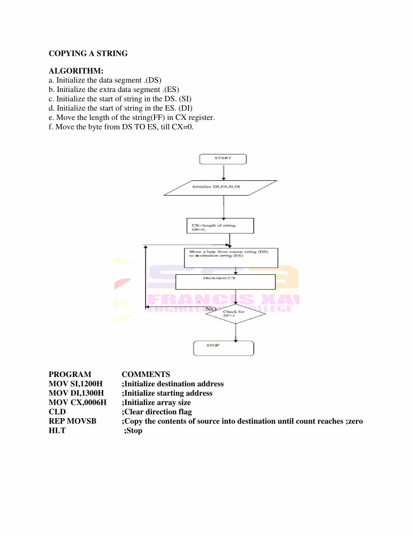
COPYING A STRING
ALGORITHM:
a. Initialize the data segment .(DS) b. Initialize the extra data segment .(ES) c. Initialize the start of string in the DS. (SI) d. Initialize the start of string in the ES. (DI) e. Move the length of the string(FF) in CX register. f. Move the byte from DS TO ES, till CX=0.
PROGRAM COMMENTS
MOV SI,1200H ;Initialize destination address
MOV DI,1300H ;Initialize starting address
MOV CX,0006H ;Initialize array size
CLD ;Clear direction flag
REP MOVSB ;Copy the contents of source into destination until count reaches ;zero
HLT ;Stop
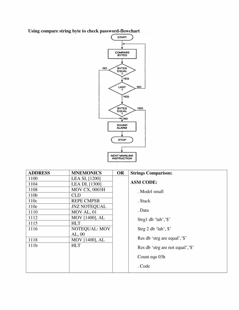
Using compare string byte to check password-flowchart
ADDRESS MNEMONICS OR Strings Comparison:
ASM CODE:
. Model small
. Stack
. Data
Strg1 db ‘lab’,’$’
Strg 2 db ‘lab’, $’
Res db ‘strg are equal’,’$’
Res db ‘strg are not equal’,’$’
Count equ 03h
. Code
1100 LEA SI, [1200]
1104 LEA DI, [1300]
1108 MOV CX, 0003H
110b CLD
110c REPE CMPSB
110e JNZ NOTEQUAL
1110 MOV AL, 01
1112 MOV [1400], AL
1115 HLT
1116 NOTEQUAL: MOV AL, 00
1118 MOV [1400], AL
111b HLT

Mov ax, @data
Mov ds, ax
Mov es, ax
Lea si, strg1
Lea di, strg2
Cld
Rep cmpsb
Jnz loop1
Mov ah, 09h
Lea dx, res
Int 21h
Jmp a1
Loop1: mov ah, 09h
Lea dx, re1
Int 21h
A1: mov ah, 4ch
Int 21h
End
Write an ALP to count the number of „1‟ in a 16 bit number. Assume the number to be stored in BX register. Store the result in CX register.
.MODEL SMALL
.DATA NUM DW 0008H ONES DB 00H .CODE MOV AX, @DATA ; initialize data segment MOV DS, AX MOV CX, 10H ; initialize rotation counter by 16 MOV BX, NUM ;load number in BX UP: ROR BX, 1 ; rotate number by 1 bit right
JNC DN ; if bit not equal to 1 then go to dn INC ONES ; else increment ones by one DN: LOOP UP ;decrement rotation counter by 1 anf if not zero then go to up MOV CX, ONES ;move result in cx register. MOV AH, 4CH INT 21H
ENDS END ; end of program.
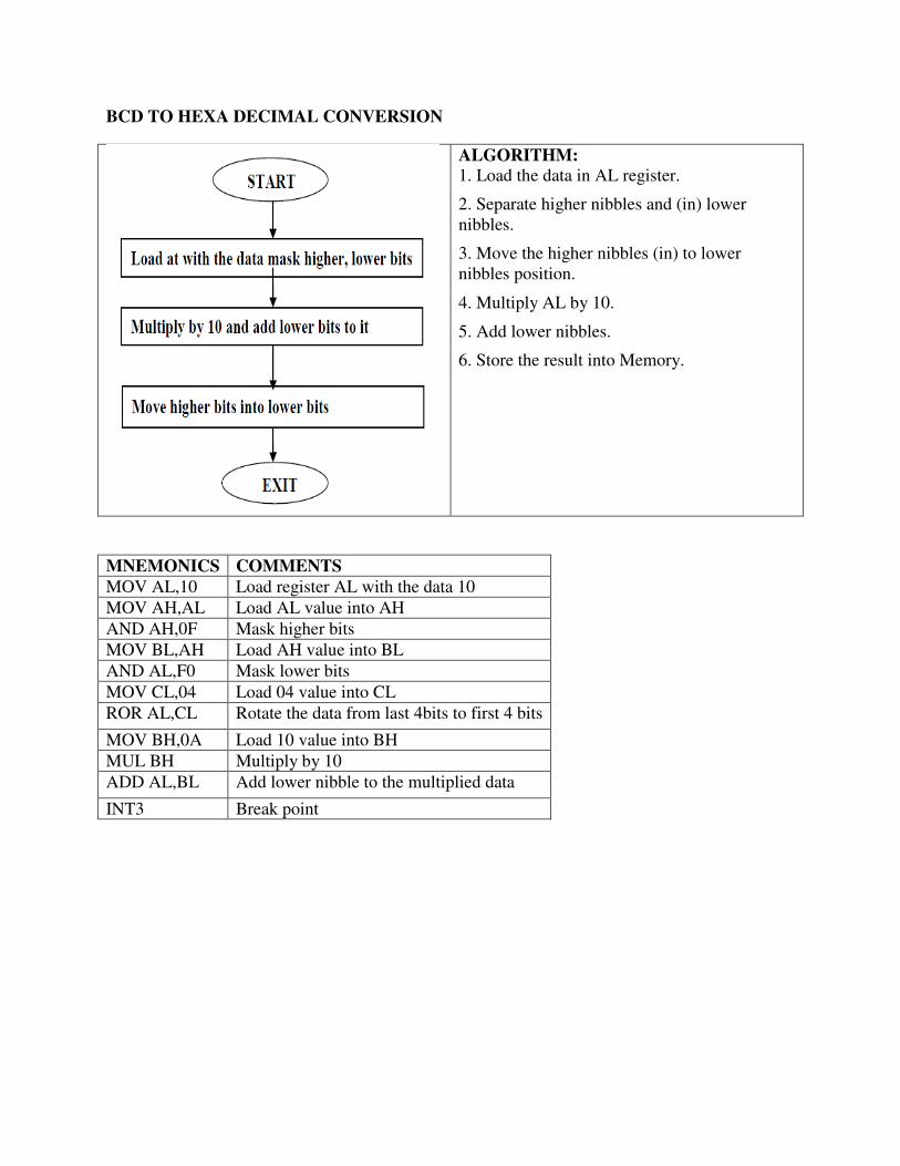
BCD TO HEXA DECIMAL CONVERSION
ALGORITHM: 1. Load the data in AL register.
2. Separate higher nibbles and (in) lower nibbles.
3. Move the higher nibbles (in) to lower nibbles position.
4. Multiply AL by 10.
5. Add lower nibbles.
6. Store the result into Memory.
MNEMONICS COMMENTS MOV AL,10 Load register AL with the data 10
MOV AH,AL Load AL value into AH
AND AH,0F Mask higher bits
MOV BL,AH Load AH value into BL
AND AL,F0 Mask lower bits
MOV CL,04 Load 04 value into CL
ROR AL,CL Rotate the data from last 4bits to first 4 bits
MOV BH,0A Load 10 value into BH
MUL BH Multiply by 10
ADD AL,BL Add lower nibble to the multiplied data
INT3 Break point

Hex to BCD number conversion
ALGORITHM- 1. Start 2. Load the hexadecimal number into a memory location 3. Divide the number separately by 64 (H) and 0A(H) and store the quotients separately in
memory location 4. The last unit digit remainder is stored separately in successive memory location 5. Stop
DATA SEGMENT HEX DB 0AFH BCD DW 0 CNT DB 0 DATA ENDS CODE SEGMENT ASSUME CS:CODE,DS:DATA START: MOV AX,DATA MOV DS,AX MOV AL,HEX CMP AL,00 JZ LAST LOOP1: MOV AH,00 MOV BL,0AH DIV BL MOV DH,00 MOV DL,AH MOV BL,AL MOV AL,04 MUL CNT MOV CL,AL ROL DX,CL OR BCD,DX MOV AL,BL INC CNT CMP AL,0 JNZ LOOP1 LAST:INT 3 CODE ENDS END START END
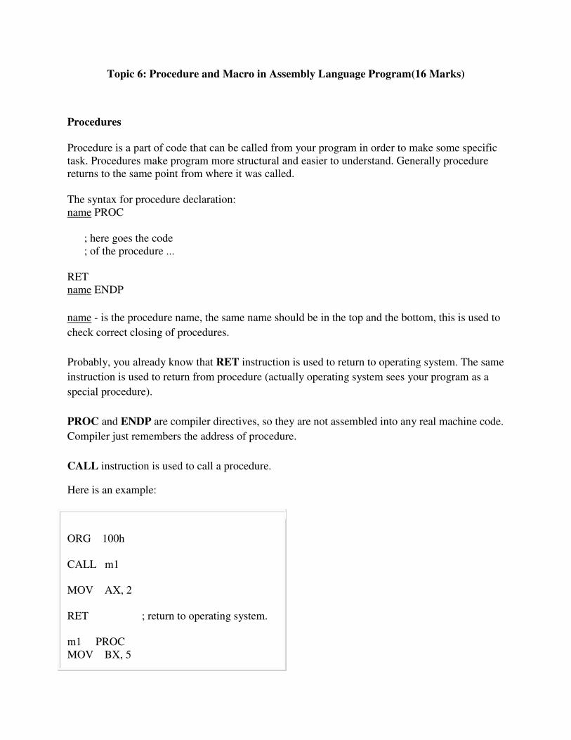
Topic 6: Procedure and Macro in Assembly Language Program(16 Marks)
Procedures Procedure is a part of code that can be called from your program in order to make some specific task. Procedures make program more structural and easier to understand. Generally procedure returns to the same point from where it was called. The syntax for procedure declaration: name PROC ; here goes the code ; of the procedure ... RET name ENDP
name - is the procedure name, the same name should be in the top and the bottom, this is used to
check correct closing of procedures.
Probably, you already know that RET instruction is used to return to operating system. The same
instruction is used to return from procedure (actually operating system sees your program as a
special procedure).
PROC and ENDP are compiler directives, so they are not assembled into any real machine code.
Compiler just remembers the address of procedure.
CALL instruction is used to call a procedure.
Here is an example:
ORG 100h CALL m1 MOV AX, 2 RET ; return to operating system. m1 PROC MOV BX, 5
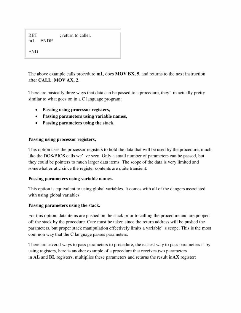
RET ; return to caller. m1 ENDP END
The above example calls procedure m1, does MOV BX, 5, and returns to the next instruction
after CALL: MOV AX, 2.
There are basically three ways that data can be passed to a procedure, they’ re actually pretty
similar to what goes on in a C language program:
Passing using processor registers,
Passing parameters using variable names,
Passing parameters using the stack.
Passing using processor registers,
This option uses the processor registers to hold the data that will be used by the procedure, much
like the DOS/BIOS calls we’ ve seen. Only a small number of parameters can be passed, but
they could be pointers to much larger data items. The scope of the data is very limited and
somewhat erratic since the register contents are quite transient.
Passing parameters using variable names.
This option is equivalent to using global variables. It comes with all of the dangers associated
with using global variables.
Passing parameters using the stack.
For this option, data items are pushed on the stack prior to calling the procedure and are popped
off the stack by the procedure. Care must be taken since the return address will be pushed the
parameters, but proper stack manipulation effectively limits a variable’ s scope. This is the most
common way that the C language passes parameters.
There are several ways to pass parameters to procedure, the easiest way to pass parameters is by
using registers, here is another example of a procedure that receives two parameters
in AL and BL registers, multiplies these parameters and returns the result inAX register:
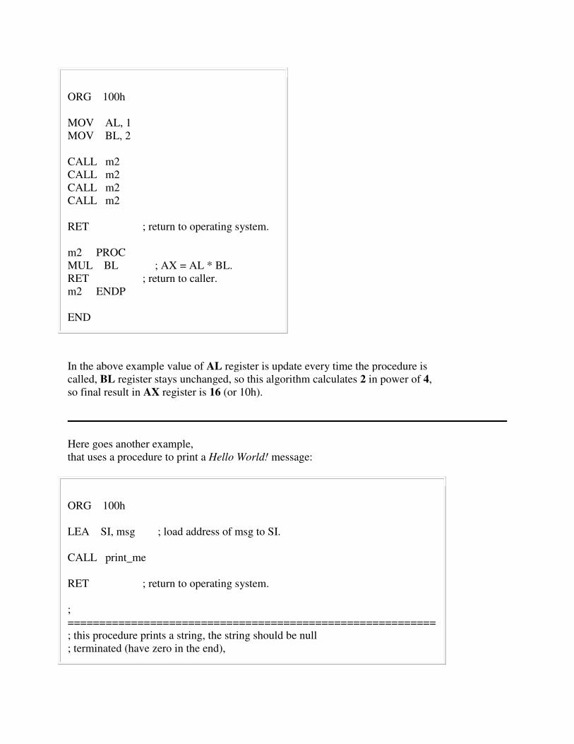
ORG 100h MOV AL, 1 MOV BL, 2 CALL m2 CALL m2 CALL m2 CALL m2 RET ; return to operating system. m2 PROC MUL BL ; AX = AL * BL. RET ; return to caller. m2 ENDP END
In the above example value of AL register is update every time the procedure is called, BL register stays unchanged, so this algorithm calculates 2 in power of 4, so final result in AX register is 16 (or 10h).
Here goes another example, that uses a procedure to print a Hello World! message:
ORG 100h LEA SI, msg ; load address of msg to SI. CALL print_me RET ; return to operating system. ; ========================================================== ; this procedure prints a string, the string should be null ; terminated (have zero in the end),
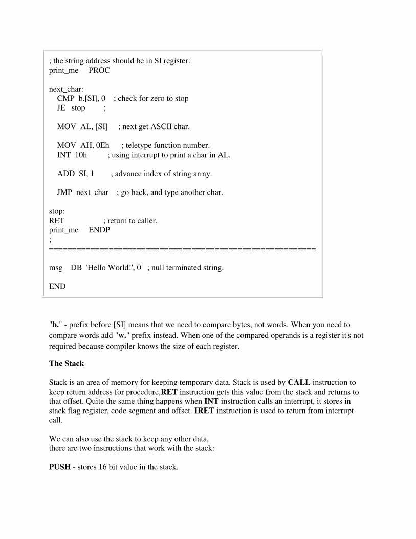
; the string address should be in SI register: print_me PROC next_char: CMP b.[SI], 0 ; check for zero to stop JE stop ; MOV AL, [SI] ; next get ASCII char. MOV AH, 0Eh ; teletype function number. INT 10h ; using interrupt to print a char in AL. ADD SI, 1 ; advance index of string array. JMP next_char ; go back, and type another char. stop: RET ; return to caller. print_me ENDP ; ========================================================== msg DB 'Hello World!', 0 ; null terminated string. END
"b." - prefix before [SI] means that we need to compare bytes, not words. When you need to
compare words add "w." prefix instead. When one of the compared operands is a register it's not
required because compiler knows the size of each register.
The Stack Stack is an area of memory for keeping temporary data. Stack is used by CALL instruction to keep return address for procedure,RET instruction gets this value from the stack and returns to that offset. Quite the same thing happens when INT instruction calls an interrupt, it stores in stack flag register, code segment and offset. IRET instruction is used to return from interrupt call. We can also use the stack to keep any other data, there are two instructions that work with the stack: PUSH - stores 16 bit value in the stack.
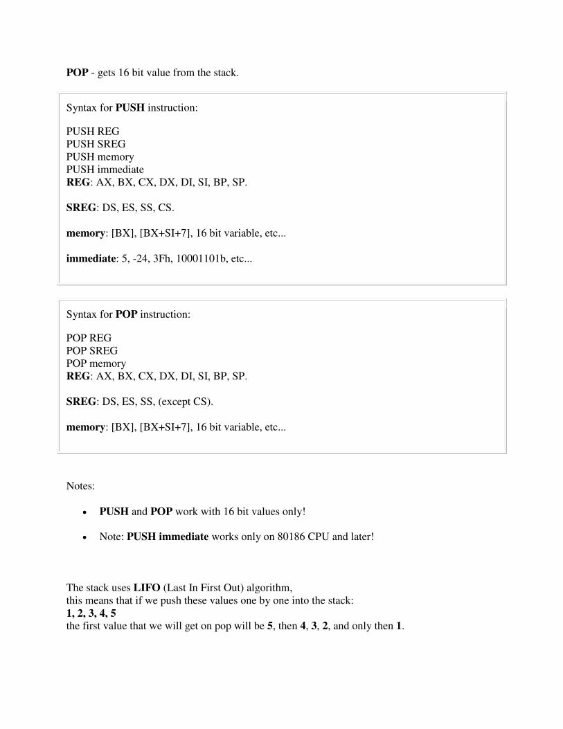
POP - gets 16 bit value from the stack.
Syntax for PUSH instruction:
PUSH REG PUSH SREG PUSH memory PUSH immediate REG: AX, BX, CX, DX, DI, SI, BP, SP. SREG: DS, ES, SS, CS. memory: [BX], [BX+SI+7], 16 bit variable, etc... immediate: 5, -24, 3Fh, 10001101b, etc...
Syntax for POP instruction:
POP REG POP SREG POP memory REG: AX, BX, CX, DX, DI, SI, BP, SP. SREG: DS, ES, SS, (except CS). memory: [BX], [BX+SI+7], 16 bit variable, etc...
Notes:
PUSH and POP work with 16 bit values only!
Note: PUSH immediate works only on 80186 CPU and later!
The stack uses LIFO (Last In First Out) algorithm, this means that if we push these values one by one into the stack: 1, 2, 3, 4, 5 the first value that we will get on pop will be 5, then 4, 3, 2, and only then 1.

It is very important to do equal number of PUSHs and POPs, otherwise the stack maybe corrupted and it will be impossible to return to operating system. As you already know we use RET instruction to return to operating system, so when program starts there is a return address in stack (generally it's 0000h). PUSH and POP instruction are especially useful because we don't have too much registers to operate with, so here is a trick:
Store original value of the register in stack (using PUSH).
Use the register for any purpose.
Restore the original value of the register from stack (using POP).
Here is an example:
ORG 100h MOV AX, 1234h PUSH AX ; store value of AX in stack. MOV AX, 5678h ; modify the AX value. POP AX ; restore the original value of AX. RET END
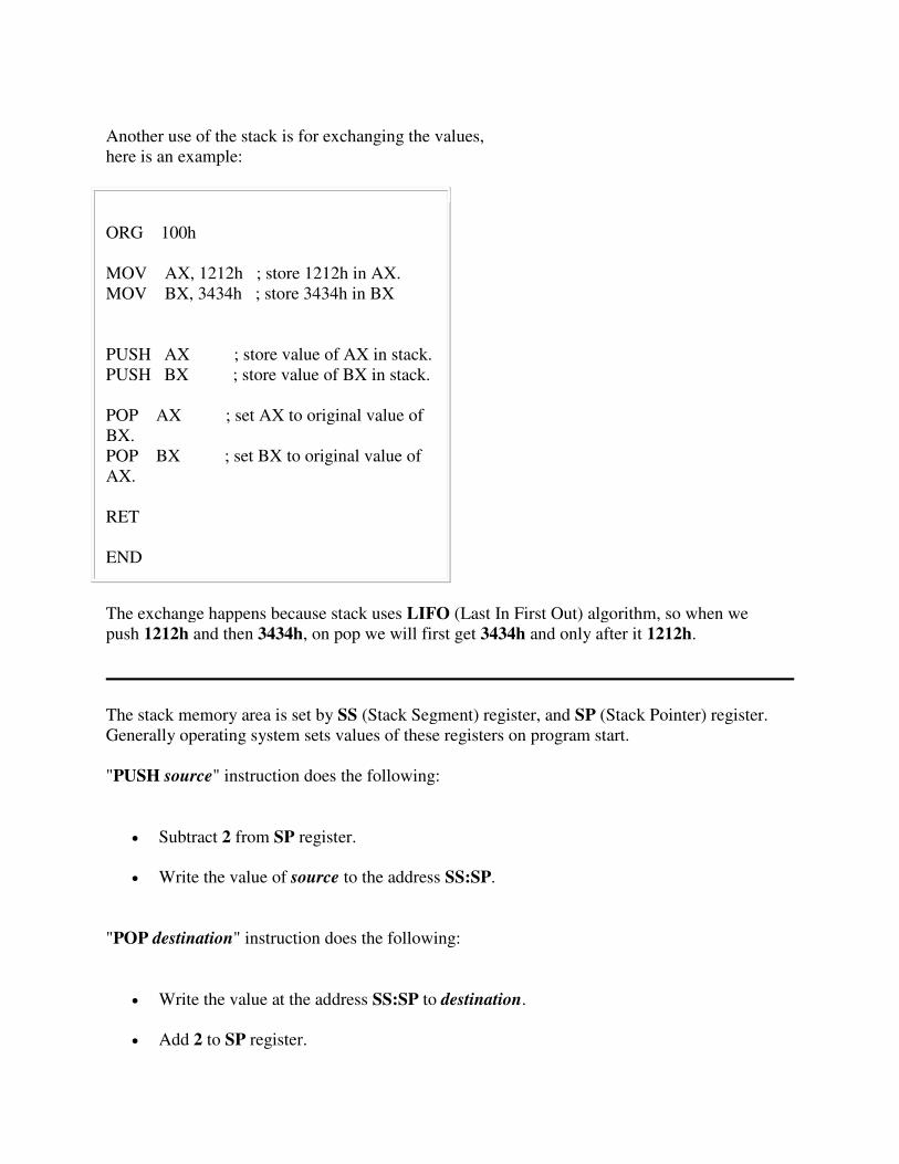
Another use of the stack is for exchanging the values, here is an example:
ORG 100h MOV AX, 1212h ; store 1212h in AX. MOV BX, 3434h ; store 3434h in BX PUSH AX ; store value of AX in stack. PUSH BX ; store value of BX in stack. POP AX ; set AX to original value of BX. POP BX ; set BX to original value of AX. RET END
The exchange happens because stack uses LIFO (Last In First Out) algorithm, so when we push 1212h and then 3434h, on pop we will first get 3434h and only after it 1212h.
The stack memory area is set by SS (Stack Segment) register, and SP (Stack Pointer) register. Generally operating system sets values of these registers on program start. "PUSH source" instruction does the following:
Subtract 2 from SP register.
Write the value of source to the address SS:SP.
"POP destination" instruction does the following:
Write the value at the address SS:SP to destination.
Add 2 to SP register.
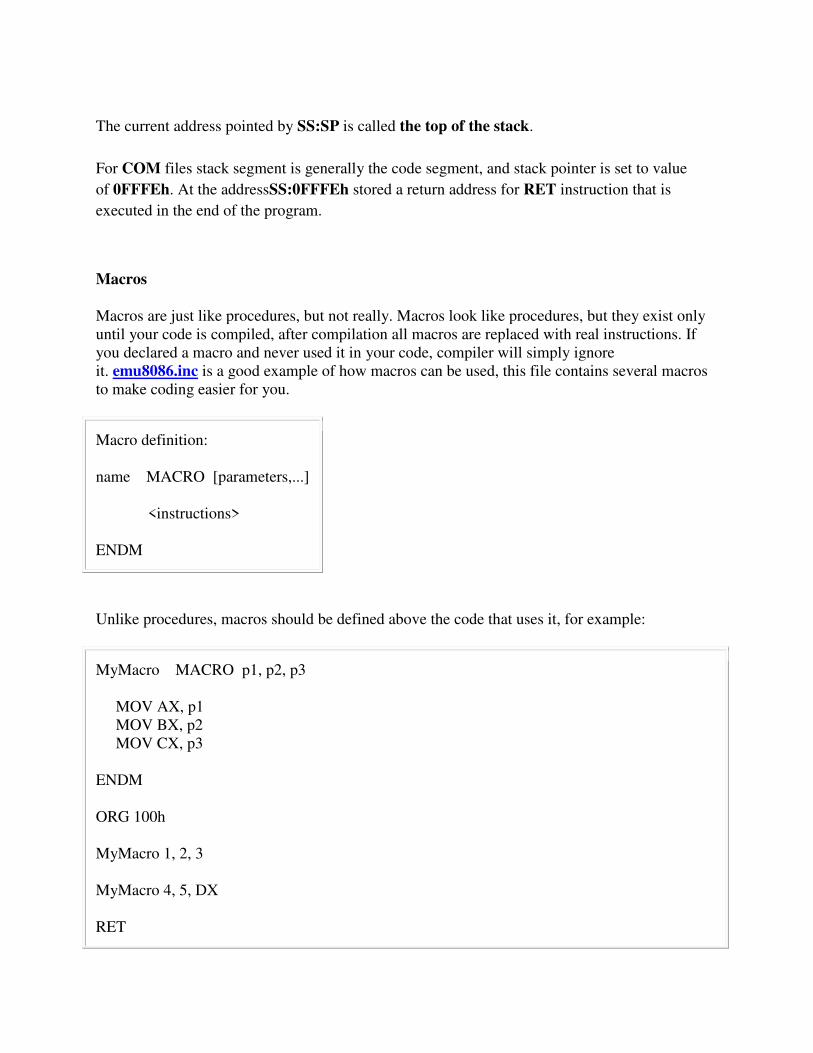
The current address pointed by SS:SP is called the top of the stack.
For COM files stack segment is generally the code segment, and stack pointer is set to value
of 0FFFEh. At the addressSS:0FFFEh stored a return address for RET instruction that is
executed in the end of the program.
Macros Macros are just like procedures, but not really. Macros look like procedures, but they exist only until your code is compiled, after compilation all macros are replaced with real instructions. If you declared a macro and never used it in your code, compiler will simply ignore it. emu8086.inc is a good example of how macros can be used, this file contains several macros to make coding easier for you.
Macro definition: name MACRO [parameters,...] <instructions> ENDM
Unlike procedures, macros should be defined above the code that uses it, for example:
MyMacro MACRO p1, p2, p3 MOV AX, p1 MOV BX, p2 MOV CX, p3 ENDM ORG 100h MyMacro 1, 2, 3 MyMacro 4, 5, DX RET
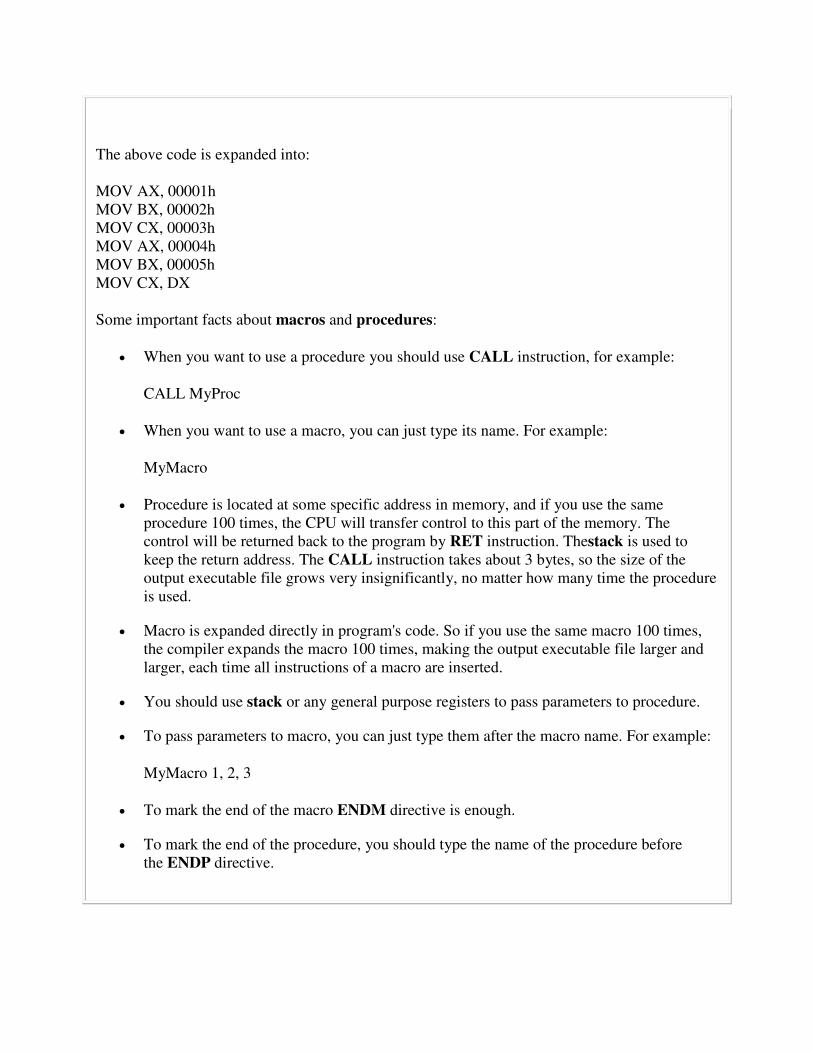
The above code is expanded into: MOV AX, 00001h MOV BX, 00002h MOV CX, 00003h MOV AX, 00004h MOV BX, 00005h MOV CX, DX Some important facts about macros and procedures:
When you want to use a procedure you should use CALL instruction, for example:
CALL MyProc
When you want to use a macro, you can just type its name. For example:
MyMacro
Procedure is located at some specific address in memory, and if you use the same procedure 100 times, the CPU will transfer control to this part of the memory. The control will be returned back to the program by RET instruction. Thestack is used to keep the return address. The CALL instruction takes about 3 bytes, so the size of the output executable file grows very insignificantly, no matter how many time the procedure is used.
Macro is expanded directly in program's code. So if you use the same macro 100 times, the compiler expands the macro 100 times, making the output executable file larger and larger, each time all instructions of a macro are inserted.
You should use stack or any general purpose registers to pass parameters to procedure.
To pass parameters to macro, you can just type them after the macro name. For example:
MyMacro 1, 2, 3
To mark the end of the macro ENDM directive is enough.
To mark the end of the procedure, you should type the name of the procedure before the ENDP directive.
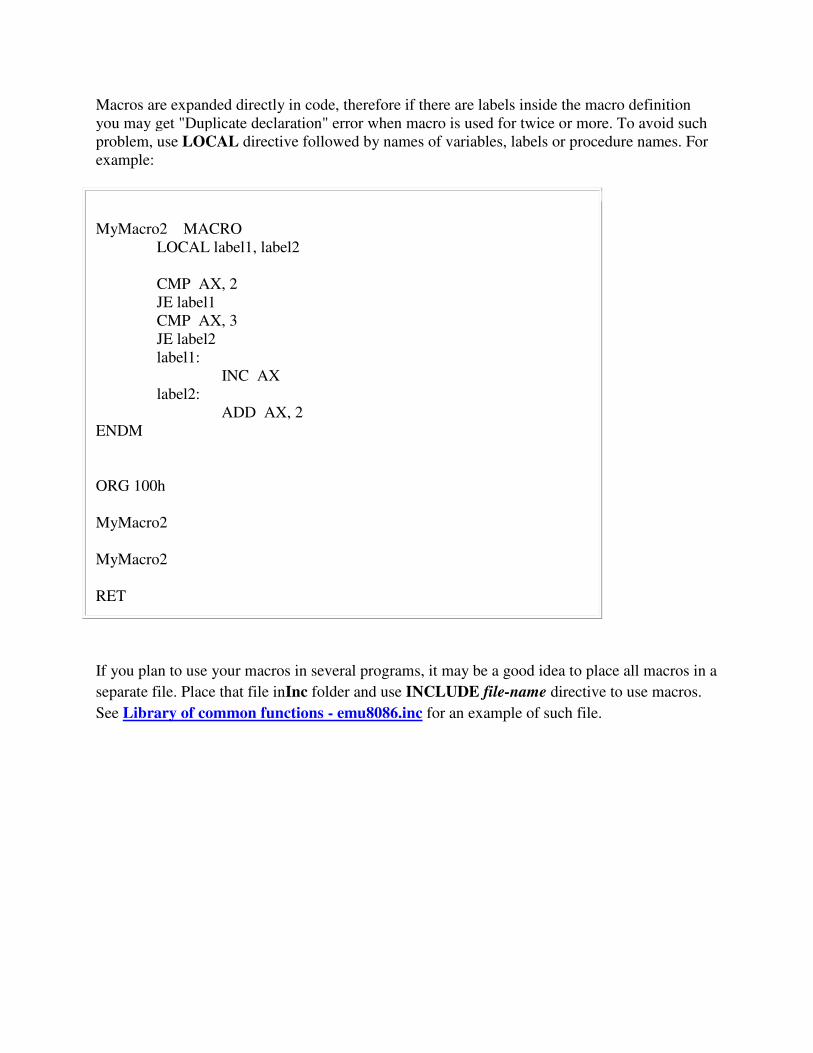
Macros are expanded directly in code, therefore if there are labels inside the macro definition you may get "Duplicate declaration" error when macro is used for twice or more. To avoid such problem, use LOCAL directive followed by names of variables, labels or procedure names. For example:
MyMacro2 MACRO LOCAL label1, label2 CMP AX, 2 JE label1 CMP AX, 3 JE label2 label1: INC AX label2: ADD AX, 2 ENDM ORG 100h MyMacro2 MyMacro2 RET
If you plan to use your macros in several programs, it may be a good idea to place all macros in a
separate file. Place that file inInc folder and use INCLUDE file-name directive to use macros.
See Library of common functions - emu8086.inc for an example of such file.
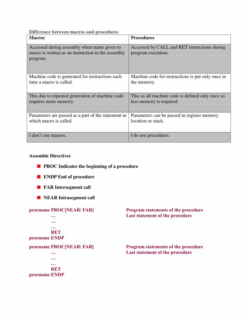
Difference between macros and procedures
Macros Procedures
Accessed during assembly when name given to macro is written as an instruction in the assembly program.
Accessed by CALL and RET instructions during program execution.
Machine code is generated for instructions each time a macro is called.
Machine code for instructions is put only once in the memory.
This due to repeated generation of machine code requires more memory.
This as all machine code is defined only once so less memory is required.
Parameters are passed as a part of the statement in which macro is called.
Parameters can be passed in register memory location or stack.
I don’t use macros. I do use procedures.
Assemble Directives
PROC Indicates the beginning of a procedure
ENDP End of procedure
FAR Intersegment call
NEAR Intrasegment call
procname PROC[NEAR/ FAR] … … … RET procname ENDP
Program statements of the procedure Last statement of the procedure
procname PROC[NEAR/ FAR] …
…
…
RET
procname ENDP
Program statements of the procedure
Last statement of the procedure
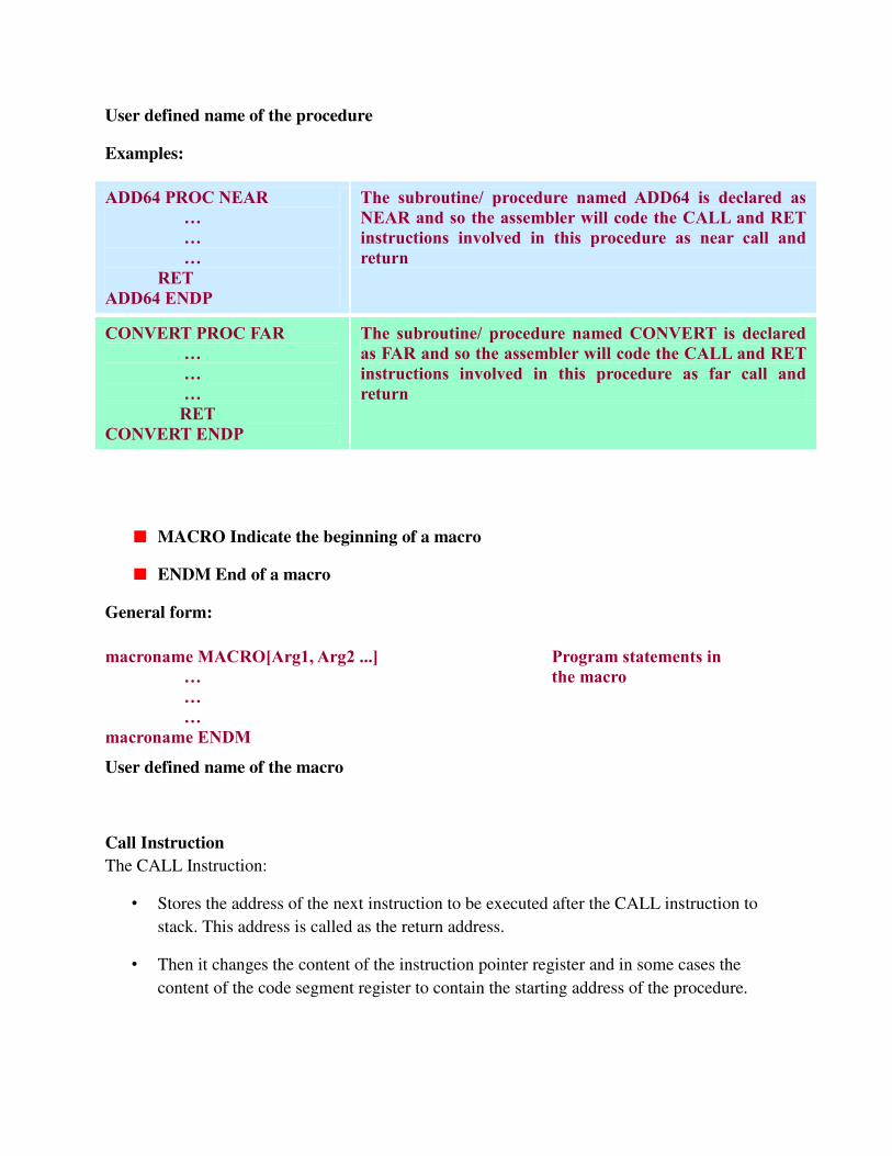
User defined name of the procedure
Examples:
ADD64 PROC NEAR … … … RET ADD64 ENDP
The subroutine/ procedure named ADD64 is declared as NEAR and so the assembler will code the CALL and RET instructions involved in this procedure as near call and return
CONVERT PROC FAR … … … RET CONVERT ENDP
The subroutine/ procedure named CONVERT is declared as FAR and so the assembler will code the CALL and RET instructions involved in this procedure as far call and return
MACRO Indicate the beginning of a macro
ENDM End of a macro
General form:
macroname MACRO[Arg1, Arg2 ...] … … … macroname ENDM
Program statements in the macro
User defined name of the macro
Call Instruction
The CALL Instruction:
• Stores the address of the next instruction to be executed after the CALL instruction to
stack. This address is called as the return address.
• Then it changes the content of the instruction pointer register and in some cases the
content of the code segment register to contain the starting address of the procedure.
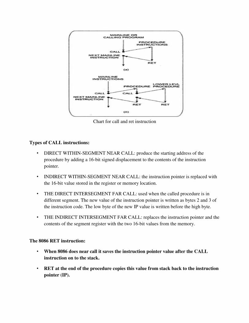
Chart for call and ret instruction
Types of CALL instructions:
• DIRECT WITHIN-SEGMENT NEAR CALL: produce the starting address of the
procedure by adding a 16-bit signed displacement to the contents of the instruction
pointer.
• INDIRECT WITHIN-SEGMENT NEAR CALL: the instruction pointer is replaced with
the 16-bit value stored in the register or memory location.
• THE DIRECT INTERSEGMENT FAR CALL: used when the called procedure is in
different segment. The new value of the instruction pointer is written as bytes 2 and 3 of
the instruction code. The low byte of the new IP value is written before the high byte.
• THE INDIRECT INTERSEGMENT FAR CALL: replaces the instruction pointer and the
contents of the segment register with the two 16-bit values from the memory.
The 8086 RET instruction:
• When 8086 does near call it saves the instruction pointer value after the CALL
instruction on to the stack.
• RET at the end of the procedure copies this value from stack back to the instruction
pointer (IP).

Opcode Instruction Description
C3 RET Near return to calling procedure
CB RET Far return to calling procedure
Description
Transfers program control to a return address located on the top of the stack. The address is usually placed on the stack by a CALL instruction, and the return is made to the instruction that follows the CALL instruction.
The RET instruction can be used to execute three different types of returns:
Near return--A return to a calling procedure within the current code segment (the segment currently pointed to by the CS register), sometimes referred to as an intersegment return.
Far return--A return to a calling procedure located in a different segment than the current code segment, sometimes referred to as an intersegment return.
Inter-privilege-level far return--A far return to a different privilege level than that of the currently executing program or procedure.
Example
Transfer control to the return address located on the stack.
ret
Transfer control to the return address located on the stack. Release the next 16-bytes of parameters.
ret $-32767
Long Return (lret)
lret
lret imm16
Operation
return to caller
Description
The lret instruction transfers control to a return address located on the stack. This address is usually placed on the stack by an lcallinstruction. Issue the lret instruction within the called procedure to resume execution flow at the instruction following the call.
Writing and debugging programs containing procedures
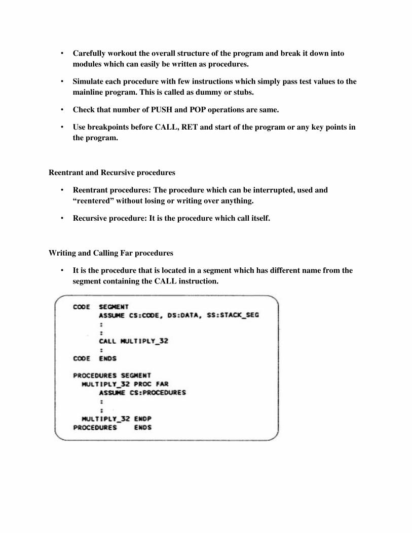
• Carefully workout the overall structure of the program and break it down into
modules which can easily be written as procedures.
• Simulate each procedure with few instructions which simply pass test values to the
mainline program. This is called as dummy or stubs.
• Check that number of PUSH and POP operations are same.
• Use breakpoints before CALL, RET and start of the program or any key points in
the program.
Reentrant and Recursive procedures
• Reentrant procedures: The procedure which can be interrupted, used and
“reentered” without losing or writing over anything.
• Recursive procedure: It is the procedure which call itself.
Writing and Calling Far procedures
• It is the procedure that is located in a segment which has different name from the
segment containing the CALL instruction.

Accessing Procedure
Accessing a procedure in another segment
• Put mainline program in one segment and all the procedures in different segment.
• Using FAR calls the procedures can accessed as discuss above.
Accessing procedure and data in separate assembly module
• Divide the program in the series of module.
• The object code files of each module can be linked together.
• In the module where variables or procedures are declared, you must use PUBLIC
directive to let the linker know that it can be accessed from other modules.
• In a module which calls procedure or accesses a variable in another module, you must use
the EXTERN directive.
Writing and using Assembler Macros
Defining and calling a Macro without parameters
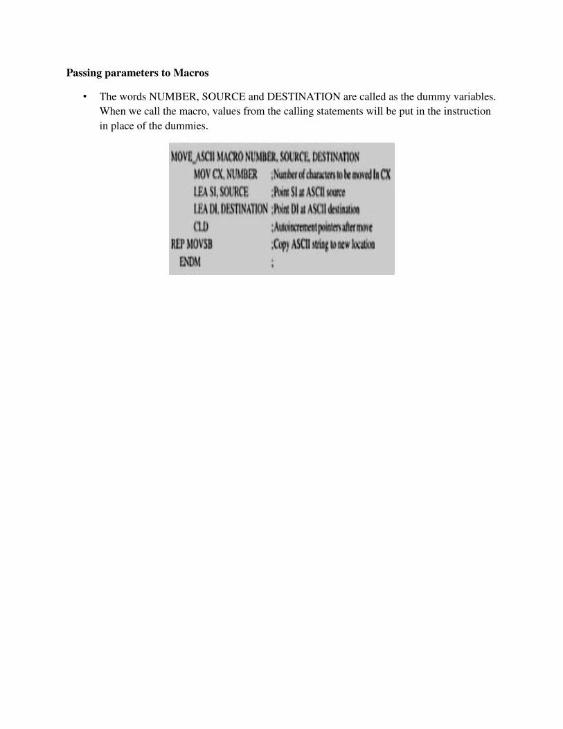
Passing parameters to Macros
• The words NUMBER, SOURCE and DESTINATION are called as the dummy variables.
When we call the macro, values from the calling statements will be put in the instruction
in place of the dummies.