0·. manuals/ims/ims cpz... · interrupts for use with z-80 mode 2 interrupts * provisions for...
TRANSCRIPT

TABLE OF CONTENTS
COPYRIGHT NOTICE. • • • • • 0 • •• • •. • •
DISCLAIMER NOTICE: ••••••••••.•••••••••••INTRODUCTION • • • • • • • • • • • • • • • • • • • •PERFORMANCE SPECIFICATIONS • • • • • • • • • • • • • • • • •FUNCTIONAL DESCRIPTION •.••••••••••••••••••
Input/Outpu1;: ,.Str:uctur·e • • • • • • • • • ••• • •Off-Board ,..1./0 Controllers. •.••••••••.•
SerialI/Q. Po~rt Control • • • • • • • • • • • • • • • •·Serial. I/;.O Cantroller ••.•••••••••••••••Baud. Rate 'Clock Gene r a tor •. • • • • • • • • • • • • • •Parallel ·I/O Port C.ontrol Interface • • •. • • • • • • •Double- ·.o.r: Single-Density E;'loppy Disk Controller. • • •
On-Board'I/O'Controllers "••••••••••••••••. DMA COritr.:oJ:ler .." ., • ~. • .'. .• • • • • • • • • • • •, . DM,~ ··Oper·at fans e ,'~ • • • • • • • • • • • • • • • • • •
.' D}lA "'Channe~l A"Ss"ignments ... • • • • • • • • • • • ••·,,····!:~~e·.r:tttp~<;Contro~'.'Logic • • • • • • • • • • • • • • • •" ~·I:*tef.rqpt.··;Controll.er/Select • • • • • • • • • • • • • •
v .' ~'·M~Ht:PfY;.l1anagementUnit • • ! • • • • • • • • • • •
.':.64~·Kb1~.~·~:Dyria~d..~. RAM/Logic • • ~ • • • •• • • • • • • • •'" 2-I<l~~.K :~:'E~ROM' '~ji'": .~.' .1' '~ ••:';' • • • •. • • • • • • • • • • • • • •
~ I)Qt Chip S~l~c,.t, .:bogie·· '. ',. • • • • • • • • • • .'. • •. • • •~:~O\fter":'on C1.ea'r/Reset. Logic • ... ,,'. • • • • • • • .'. • • • •Clock'G~nerat6t •••• ; •••••••••••••••••
"CPU Control'Signals Generator • • • • • • • • • • • ••'S-lOO'Bus Control Signals Generator. •• • ••••••:'S~~OO'BuS!n~e~face••••••••••••••••••••'····AddreSs··Bus·· •. :. .0·. •. . • . . • . . . • . • ..:!npUt··Data Bus 4! • • • ••••••••••••••••
::. Output Data·Bus • • •.• • • • .• • • • • • • • • • • • • • •:"'Status Bus .'., .• • • .'. • • • • • • • • • • • • • • .' •
:.'. $MEMR (Memo.r.y, Read) • • • • • • • • • • • • • • • • • • •~. :~Ml (Op¢od~Fetch) ••• • •••••••••••••. ::;~INP(Input) ••••.••••••••••••••••••. '", :~:5·~~T .. (Out'put) ~.'. • • • • • • • • • • • • • • • • • •
:' 1 " sWQ*·· {w r ~ te ~-Cy~le) •••••••••••. • • • •.. ~~~~'~~A (!rif;er~upt Acknowledge) • • • •.• • '. • • • • •
.. ";"'s£J!iTA. (Hal t ~Ac.know1edae) .......;;.......:.:q~~;;6.i.:lnput-B0:5 ••• "' ••• 0 . e • • • ••••
. ~J';:;j ~l~ve Re?l<;Jy) .'. • • .....' • • • • • • • • • • • • • •-~f%~¥:: t~}}.eC!al·' Ready) ..•.•. it.. • '., • • • • • • • • • • • • •
'I~~*'" '(Ll-1as~ab-l e ,Interrupt Request) • • • • • II'. • •
.NMI *.lNon~.ma!?kabl e In.ter r upt Requ~st) '. • • • • • •HOLD* '.(DMA·;·~R~~est) • • • -. • • •• • • • • 5 • • • • •
ControlOu~p~t,~:Bus·-". • • .'. ••••••••••••. pSYNC (Cyc'l~~~::S:~!~) _~.'. .' •• • ." • • • • • • • • • • • •
. pSTV~ * (~~~~(l~··":;:~Yal..;J~l •. ':." .~'. • •.• '. • . • .• • • • • •pDB I N (Read :S:.ttobe) .... • • ". ...:' • • • • • •• • • •
I1235566678999
1010
.~J~""14.
"1·3';"· .1415151616161717181819191920202020202021212121222222232323

pWR* (Wri te Strobe) .'. • • • • • • • • • • • • • • • 24pHLDA (Hold Acknowledge) • • • • • • • • • • • • 24pWAIT (Wai t [optional]) • • • ••• • • • • • • • 24
DMA Control Bus • • • • • • •• ••••••• • • • • • 24Vector Interrupt Bus • • • • • • • • • • • • • • • • • • • 25utility Bus • • : • • • • • • • • • • • • • • e • • • • •• 25System Clock (Master Clock) • • • •• • • • • • • • • • 26Clock (Clock) • • • • • • • • • • e e • • • • • • e • • • • 26MWRITE (Memory Write) ••••••• e • • • • • • • • • • • 26POC* (Power-on Clear) • • e • • • ••••• • • • • • • 26Slave CLR* (Slave Clear) ••••••••••••••••• 26ERROR* (Error line) • e • • • • • • ••• e •••• e • 27PWRFAIL* (Power Failure Line) e •••• e • e e. •• 27System Power e • e • • • • • • • • • • • • • e • '. • • • • 27
MANUFACTURER SPECIFIED LINES • • • • • • • • • • e • • • •• 28IPROCESS* (Inter rupt in Proces s line) • • • • • • • • • • • 28PCHAIN (Interrupt Priority Line) ••••••••••.••• 28RFSH* (External Memory Refresh Line) ••••••••••• 28Reserved Lines •••••.• •.• • • • •• • •...• • • • • • • 28
OPERATING INSTRUCTIONS • • • e • • e • • • • • • • • • • • • 2'9HARDWARE SETUP INSTRUCTIONS • e. • • • • • • • • • • • • • • • 29JUMPER OPTIONS • • • • • • • • • • • • • • • • • • • • • • • 29
JA - (Floppy Disk Controller Clock option) •••••••• 29JB - (Eprom Option) '. • • • • • • • • • • • • • • • • • • • 30JC - (Interrupt Controller options) • • • • • • • • • • • • 30JD - (MWRITE jumper option) • • • • • • • • • • • • • • 31JE - (IEEE/Z-80 timing option) • e • • • e •• e • • • 32.JF - (IEEE/TRANSPARENT Status option) e •••• e • • • • • 32
SOLDER/TRACE CUT OPTIONS (** NOTE ** Read this section) •• e 33PJA - (SIO channel A clock option) • e • • • • • • • • • • 33PJB - (SIO channel B Clock option) •• • • • • • • • • 34PJC - (Off Board Interrupt Priority option) ••• e e • 34PJD - (Off-Board Interrupt chain option) •• e • • e • • • 34PJE - (Z-80 Refresh output option) • e • • • e • • • • 35PJF (S-lOO Ground Pin options) e •••••••••• e.. 35
PERSONALITY BOARD INSTRUCTIONS • • • • • • • • • • • • • • • 36SOFTWARE SECTION • • • • • •• •• • • • • • • • 37
PROM Monitor • • • • • • • • • • • • • • • e e • • • e • • 37Basic PROM Commands • • • • • e • • • • • e • e e e 37PROM Monitor Display Options •• e e ••••• e • • • 39
I/O PORT ADDRESS ASSIGNMENTS e • e • • • • • • • • • • • • • 40Control Register Bit Assignments • e • • • • • •• • • 42DMA Register Bit Assignments· • • e • • • • • • • • • • • • 44
SERIAL PORT A and B SOFTWARE DESCRIPTION • • • ~ • • • • • • 46Channel A and B Baud Rate Software Example • • • • • • 47

CPZ-48000 CPU Manual Manual Revision 1.0 of 3-4-82
*********************************************************** COPYRIGHT (C) 1982 Intercontinental Micro Systems Corp ***********************************************************
All information contained herein is proprietary too Intercontinental Micro Systems Incorporated and may not be reproduced,transmitted, transcribed, stored in a retrieval system, or translatedinto any language or computer language, in any form or by means,electronic, mechanical, magnetic, optical, chemical, manual orotherwise, without the prior written permission of IntercoritinentalMicro Systems, Corp. 1733 South, Douglass Rd. Suite E, Anaheim,
. California. 92806
DISCLAIMER
Intercontinental Micro Systems. Corp. makes no representations orwarranties with respect to the contents hereof and specificallydisclaims any implied warranties of merchantability or fitness for anyparticular purpose. Intercontinental Micro Systems Corp. reserves theright to revise this publication and to make changes from time to timein th~ content hereof without obligation of Intercontinental ~icro
Systems Corp. to notify any person of such revision or changes •
. (Information contained herein is Proprietary to I.e.M. Corp.)

CPZ-48000 CPU Manual Manual Revision 1.0 of 3-4-82
**** INTRODUCTION ****The INTERCONTINENTAL MICRO SYSTEMS CORP. (ICM) CPZ-48000 single
board central processor is a Z80A (tm) based computer board designedto meet or exceed the IEEE S-lOO Bus specification. This thirdgeneration· computer incorporates all the features necessary for acomplete, stand alone CP/M (tm) system and is perfect for use inmulti-processor or multi-user/multi-tasking architectures titilizing
. operating systems such as MP/M (tm), OASIS (tm), TURBODOS (tm)· andCP/NET (tm).
Features such as an independent interrupt structure, DirectMemory Access, a 16 Megabyte Memory Management Unit and a bankselectable on-board 64K memory coupled with I/O devices such as afloppy disk controller, a 2~port serial controller and a 2-portparallel controller provides the user computing power on a singleboard heretofore unmatched in the S-lOO Bus industry. Other featuresincorporated ·are listed as follows:
FEATURES
* IEEE S-IOO Bus Compliance* Z80A (tm) 4MHz Operation* Single or Double Density Floppy Disk controller with up to
four a" or 5 1/4" floppy disk drives in either DMA, Interruptor Programmed I/O mode.
* Two Serial I/O channels with one channel programmable in eitherDMA, Interrupt or Programmed I/O mode.
* Two Parallel I/O channels with one channel programmable ineither DMA, Interrupt or Programmed I/O mode.
* Four Cha~nel Direct Memory Access Controller* 64 Kbytes of On-Board Dynamic RAM with Memory Deselect of 4
-Kbytes to 64 Kbytes under software control* Memory Management of 16 Megabytes of system memory* Eight Vectored Priority Interrupts chained together with I/O
Interrupts for use with Z-80 Mode 2 Interrupts* Provisions for either a 2 Kbyte or 4 Kbyte on-board EPROM
(Moriitor. in a 2 Kbyte EPROM supplied with board.)* Software 'Selectable Baud Rates* Real Time Clock* Synchronous or Asynchronous operation using the Z80A SIO chip* CP/M (tm) and MP/M (tm) Operating Systems available* Turbo-Disk (tm) Implementation Included
(Information contained herein is Proprietary to I.C.M. Corp.)
2

CPZ-48000 CPU Manual
MICROPROCESSOR
Manual Revision 1.0 of 3-4-82
PERFOR~_~NCE SPECIFICATIONS
Clock rate •••••••• •ir• ••••••••••••••••••••••••••••••••••••••••.••• 4MHz~!?~ •••••• ~. • ••••••••••••••••••••••••••••••••••••••••••• ~ ••••• Z80li
BUS INTERFACE••• ~ ••••••••••••••••••••••••••••••••••••••••• IEEE S-lOOSERIAL I/O CH1u\1NELS
Synchronous OperationBaud Rate •••••••••••••••••• ~~~oooeeee•••• ~ •••••••• Uo to SOOK BaudData Transfer •••••••••••••••••••• DMA, Interrupt or Programmed I/O
Asynchronous OperationBaud Rate " 0 Up to SOK BaudClock Rate •••••••••••••••••••••••• l, 16, 32 or 64 Times Baud RateBits/Character ••••••••••••••••••••••••••••••••••••••• 5, 6, 7 or 8Stop Bits •••••••••••••••••••••••••••••••••••••••••• 1, 1 1/2 or 2Parity •••••••••••••••••••••••••••••••••••••••••• Odd, Even or NoneData Transfer •••••••••••••••••••• DMA, Interrupt or Programmed I/OI/O Interface •••••• ·•••••••••••••••••••• Through Personality Boards
PARALLEL I/O CHANNELSData Rate •••••••••••••••••••••••••••••••••••••• Up to 300K Bytes/SecChannel A Data Transfer •••••••••••• DMA, Interrupt or Programmed I/OChannel.B Data Transfer ••••••••••••••••• Interrupt or Programmed I/OInterface Signals ••••••••••••16 Data Lin~s Plus 4 Handshaking LinesI/O Interface ••••••••••••• ~ •••••••••••••• Through Personality Boards
FLOPPY DISK CONTROLLERData Rate/8-Inch Double-Density •••••••••••••••••••• SOO,OOO Bits/SecData Rate/a-Inch Single-Density •••••••••••••••••••• 250,OOO Bits/SecData Rate/5 1/4-Inch Double-Density •••••••••••••••• 2S0,OOO Bits/SecData Ratei5 1!4-Inch Single-Density •••••••••••••••• 125,OOO Bits/SecFormat •••••••••••••••••••••••••••••••••••••• IBM 3740 or 512 sectorsData Transfer •••••••••••••••••••••• DMA, Interrupt or Programmed I/OI/O Interface •••••••••••••••••••• ·•••••••• Through Personality Boards
INTERRUPT CONTROLNumber of Channels •••••••••••••••••••••••••••••••••••••••••••••••• 8Priority •••••••••••••••••••••••••••••••••••••••••• Rotating or FixedInterrupt Modes •••••••••••••••••••••••• Z80 Mode 0, Mode 1 or Mode 2
REAL-TIME CLOCKOp~ration ••••••••••••••••••••••• Software Polled or Interrupt DrivenRange ••••••••••••••••••••••••••••••••••••••••• 37.5 Hz to 1.2288 MHz
(InformatioA contained herein is Proprietary to I.C.M. Corp.)

CPZ-4aooo CPU Manual Manual Revision·l.O of 3-4-82
64K DYNA}lIC RAM MEMORYBank Selection••••••••••••". May be bank selected in increments of 4K
to 64K commencing at 4K boundaries; e~g. 8K of memorymay be selected or deselected commencing at locationCOOO(hex} as defined by' software. . .
Wait States ••••••• ~ •••••••••••••••••••••••••••••••••••••••••••• NoneDirect Memqry Transfers ••••••••••••••••••••• To/From SIO, PIO or FDC
DIRECT MEMORY ACCESS CONTROLLER .Channel O••.••••••••••••••••• Cascade Mode for IEEE S-IOO Bus or Used
with Channel 1 in Memory-to-Memory TransfersChannel 1 ••••••••••••••••••••••••••••••• Channel A of SIO ControllerChannel 2 •••••••••••••••••••••••••••••••••••• Floppy 'Disk ControllerChannel 3 ••••••••••••••••••••••••••••••• Channel A of PIO Controller
EPROMType •••••••••••••••• ~ •••••••••••••••• 2716 2K EPROM or 2732 4K EPROMWait States •••••••••••••••••••••••••••••••••••••••••••••••••••• NoneFunctions •••••••••••••••••••••••••••••••••••••••• Bootup and Monitor
POWER REQUIREMENTSVoltages ••••••••••••••••••••••••••••••••••••••• +8 VDC @ 2.5 A (max)
+16··· [email protected] A (max)-16 VDC @ 0.2 A (max)
Power • • • • • • • • • • • • • • • • • • • • • • • • • • • • • • • • • • • • • • • • • • • • • • •.• • • • •22 W (max)OPERATING ENVIRONMENT
Temperature ••••••••••••••••• ~ ••••••••••••••• O to 45 Degrees.CelsiusRelative Humidity •••••••••••••••••••••••••••••••••••••••••• O to 95%
CONSTRUCTION .Circuit Board••••••• Four Layer Glass Epoxy, Soldermask over Copper.
. All IC's in SocketsConnectors ••••·•••••••••••••••••••••••••••••• Shrouded for Protection
TESTING •••••••••••••••••••••••••••••••••••••••••• Tested and Burned-InWARRANTY ••••••••••••••••••••• Full One Year Warranty (Parts and Labor)
* zao is a Trademark of Zilog, Inc.CP/M, MP/M and CP/NET are Trademarks of Digital ResearchOASIS is a Trademark of Phase One SystemsTURBODOS is a Trademark of Software 2000, Inc.
(Informaticf contained herein is Proprietary to I.C.M. Corp.)
4

CPZ-48000 CPU Manual Manual Revision 1.0 of 3-4-82
**** FUNCTIONAL DESCRIPTION ****The CPZ-48000 is functionally partitioned into the following
major groups:
- INPUT/OUTPUT STRUCTURE- OFF-BOARD PERIPHERAL CONTROLLERS
-' SERIAL I/O PORT CONTROL- PARALLEL I/O PORT CONTROL- FLOPPY DISK CONTROL
- ON-BOARD PERIPHERAL CONTROLLERS- DMA CONTROL- INTERRUPT CONTROL- MEMORY MANAGEMENT UNIT
- 64 KBYTE DYNAMIC RAM/LOGIC- 2/4 KBYTE EPROM
'- INPUT/OUTPUT CHIP SELECT LOGIC- CPU. CONTROL SIGNALS GENERATOR- CLOCK GENERATOR
POWER-ON CLEAR/RESET LOGIC- 5-100 BUS INTERFACE
Each group is described below to give the user .a clearunderstanding of the hardware and software setup' options and to give afull appreciation of the computing power available to the user.
INPUT/OUTPUT STRUCTURE
As a point of reference, an I/O device is defined as 'a devicewhich, under program control of the zao CPU, controls a periphel:aldevice or memory.
The I/O devices contained on the CPZ-48000 consist of:
- Z80A 510-0 (Serial Port Controller, SIO)-.ZaOA PIO (Parallel Port Controller, PIO)~ ~VD1793 + SUPPORT CHIPS (Floppy Disk Controller, FDC)
AM 95l7A-4 (Direct Memory Access Controller, DMA)- AM 95l9A (Universal Interrupt Controller, UIC)- 8253 (Programmable Timer/Counter, PTC)- 74LS610 (Memory Management Unit, MMU)
Of these, the first three are used to communicate with off-boardperipheral devices and will be referred to as the "OFF-BOARD"peripheral I/O controllers. The remaining are nON-BOARD" I/Ocontrollers.
(Information contained herein is Proprietary to I.e.M. Corp.)
5

CPZ-48000 CPU Manual Manual Revision 1.0 of 3-4-82
Programmed I/O, Interrupt or Direct Memory Access (DMA) ispossible to/from SIO port A, PIO port A and the FDC. No DMA is'possible for SIO port B or PIO port B. A DMA port is assigned to theS-IOO Bus DMA request line to allow temporary bus masters to capturethe bus for DMA transfers to off-board memory. Either fixed orrotating priority selection allows arbitration between internal DMAand external DMA requests from the 'S-IOO Bus. Selection of fixedpriority gives the S-IOO Bus the highest priority and PIO port A, thelowest. Thus,
DEVICE PRIORITY------ --------5-100 Bus 1 HighSIO A 2FDC 3PIO A 4 Low
The CPZ-48000 uses 128 of it's possible 256 I/O port address foron-board usi. The range us~d is from 80 Hex to FF Hex. Please refer
. to the SOFTWARE Section of ·this manual·for·furthe·rexpla-n-a-tion•.
OFF-BOARD I/O CONTROLLERS
The Off-Board I/O Controllers consist of the Serial I/O PortControl, Parallel I/O Port Control and the Floppy Disk Control.
SERIAL I/O PORT CONTROL
The Serial I/O Port Control consists' of the Serial I/OController and the Baud Rate Clock Generator.
Serial I/O Controller
. The Serial I/O (SIO) Controller is a programmable dual channeldevice which provides formatting for serial data communications. Thechannels can handle either asynchronous or synchronous data transfersto/from serial peripheral devices. The SIO operates either underprogrammed I/O, Interrupt Control or DMA control. DMA is provided forPort A only. All lines necessary to handle asynchronous, synchronous,synchronous bit oriented protocols and other serial protocols areavailable to the user at the interface connectors. In addition, +/16 volt DC and +5 volt DC power are available at these connectors.
(Information contained herein is Proprietary to I.C.M. Corp.)
6

CPZ-48000 CPU Manual Manual Revision 1.0 of 3-4-82
The SID may be 'interfaced to peripheraldiffering protocols. This interface is tailoredrequirements by use of a Personality Module.implemented through two 16-pin Ansley connectors.for a description of the serial Personalityavailable. r
devices requ~r~ng
to -the exact deviceThe interface is
Refer to Appendix AModules currently
To program the SID, the system software issues commands toinitiate the mode of operation. Seven write registers exist forthat purpose. In addition, three read registers allow the programmerto read the status of each channel.
Baud Rate Clock Generator
The Baud Rate Clock Generator consists of a clock generator andan 8253 Programmable Interval Timer.- The 8253 is a device which,under software control, can generate variable clock periods which area multiple of the base input clock. The device has other modes ofoperation; however, only the mode applicable to the CPZ-48000operation will be described here. This is Mode 3, the square wavegenerator mode.
The 8253 consists of three channels, each with a clock input anda gate input. Channel 0 is tied to SID channel A transmit andreceiver clock inputs, chann~l I to SIO Channel' B transmit andreceiver clock - inputs, and channel 2 to the interrupt select jumperarea (as a select input to the 9519A Interrupt Controller). Channels0, and I are intended for baud rate clocks, whereas channel 2 is'intended for the "real time" clock.
Channels 0 and I are connected to the SID inputs via- jumperoption~ PJB and PJA. These signals are also tied to the serialinterface connectors. If clock signals are originated -by theinterfacing devices, the jumpers are cut appropriately.' The channel Ajumper provides for separate transmit and receive clock inputs fromthe interface (connector J2) or may serve as baud rate generatoroutputs to the interface. This arrangement is intended to provide- aclock to synchronous MODEM's via "external" clock (pin 24 of the S-IOOBus) in accordance with the EIA RS-232C standards. The modem can thenreturn a transmit/receive clock to the serial controller. In summary,means are provided to implement serial interfaces acccw~odating
asynchronous, synchronous, HDLC and a great number of currentlydefined communications protocols •
. While operating in Mode 3, the 8253 generates a square wavewhose period is defined by a count programmed into the respectivechannel's counter. The square wave will remain at a logical ZERO
,(Information contained herein is Proprietary to I.C.M. Corp.)
i

CPZ-48000 CPU Manual Manual Revision 1.0 of 3-4-82
state for one half the count, and at logical ONE for the rema~n~ng
half of the count. The counter decrements for each clock period thatis received.
The 8253 is programmed by the CPU specifying the mode, loadingsequence and counte~ contents. The Baud rates that can be derivedfrom the 2.4576 Megahertz clock are listed as follows:·
0.81.21.762.1522.44.89.619.228.832.038.457.676.8115.2153.6307.2
Baud Rate
5075110134.5150300600
1200180020002400360048007200960019200
Theoretical Frequency (16 x clock)
kiloHertzkiloHertzkiloHertzkiloHertzkiloHertzkiloHertzkiloHertzkiloHertzkiloHertz
,k:i..loHert:zkiloHertzkiloHertzkiloHertzkiloHertzkiloHertzkiloHertz
PARALLEL I/O PORT CONTROL INTERFACE
The parallel I/O Port Control Interface consists of the ParallelI/O Controller (PIO). The Parallel I/O Controller is a programmabletwo-port LSI component, which interfaces peripheral devices to the Z80microprocessor. The PIO provides data transfer to and from peripheraldevices under programmed I/O, interrupt control o~ DMA ·control.Handshaking data transfer control lines are provided to the interfacein addition to the two eight-bit data ports. ~he CPU reset line and~he CPU clock are also connected to this interface. The PIO is.flexible and may be connected to peripheral devices requiringdiffering protocols.
The interface is tailored to the exact device requirements byuse of a "Personality Module". The Personality Module is a smallexternal circuit board which connects to the CPZ-48000 to provide thehardware drivers and receivers, logic and other circuitry as required.Refer to Appendix A for a description of the parallel PersonalityModules currently available.
(Informatic~contained herein is Proprietary to I.C.M. Corp.)
8

CPZ-48000 CPU Manual Manual Revision 1.0 of 3-4-82
An interrupt line is brought into. the interface to give the userthe capability of servicing interrupts. The interface is implementedthrough a 26-pin Ansley connector.
To program the PIO, the system software issues commands toinitialize the mode of operation. Initialization is provided byloading the interrupt vector, mode, I/O and interrupt controlregisters.
Double-.or Single-Density Floppy Disk Controller (FDC)
The CPZ-48000 uses the Western Digital WD1793 or the FujitsuMB8877 Floppy Disk Controller plus the w~2l43 and WD169l support chipsas the basis for the controller. A reliable phase-lack-loop circuit'is implemented giving the user error free disk operation. Up to four8-inch or 5 1/4-inch Floppy Disk drives may be connected. A· mix ofsingle- or double-sided drives and of single- or double-density drives
·may be interconnected. The only limitation is that 8" and 5 1/4"drives cannot be mixed. Any combination of single/double sided andsingle/double density drives may be connected. .
The .FDC is connected to the drives via a Personality boardFPBlOO-XY and an adaptor board depending on the type of drive (8" or 51/4") and type of cable. For example, an FPB100-ll consists of thepersonality board and an edge card connector adapter for 5 l/4-inchFloppy drives. Header plug connector adaptors are also available.
A jumper option on the.FPBlOO-XY allows the user to configurethe board for either a-inch or 5 1/4-inch. This technique greatlyreduces the overall cost of interfacing to floppy drives •. with a lowcost personality board and even. lower cost adaptor, the user mayconnect the drive configuration fitting his particular needs.
ON-BOARD I/O CONTROLLERS
. The On-Board I/O controllers consist of the DMA Controller,Interrupt Control Logic and the Memory Management Unit.
DMA Controller
The DMA Controller consists of the 95l7A-4 Multimode DMAController, .which is a LSI component designed to allow externalperipheral devices to transfer data directly to and from the on-board
(Information contained hereiri is Proprietary to I.C.M.Corp.)
9

CPZ-48000 CPU Manual Manual Revision 1.0 of 3-4-82
system memory. The use of this data transfer technique greatlyenhances the system data throughput because the Z8Q microprocessordoes not have to deal directly with the transfers, and is free toperform other computing functions.
DMA Operations
The 95l7A is a programmable device, which enables the programmerto free the CPU from the repetitive task of controlling data blocktransfers by providing "external" hardware control over suchoperations. For example, the programmer may specify that a data blockof "X" number of bytes contained in system memory starting at location"Y" is to be transferred. The programmer may further specify that atthe end of said transfer an interrupt is to be, generated (perhaps toinitiate a subsequent transfer, or to determine the peripheral devicestatus prior .to initiating a subsequent transfer). Alternately, theprogrammer may wish to automatically re-initialize the data block~transier ~ Oncethe-software commandi·stran·smitt-ed--tot-he95-17A, it·performs all of the indicated actions without further supervision fromthe zao microprocessor. In all cases, the user of the CPZ-48000 hasfull control over these parameters and events by having the capabilityto access any of 27 data and control registers. . Once the DMA 'transferhas begun (also enabled under software control), the CPU may then be
.used for other processing or for controlling other peripheral datatransfers in a similar manner.
The DMA Controller may be operated in either burst or cyclestealing mode. Cycle-stea~ing is recommended if concurrent CPUprocessing is desired while I/O processing is taking place. Burstmode is recommended for operating with fast peripheral devices whichcould lose data if not responded to ~n a timely fashion. The transferrate is 1 megabyte/sec. with DMA operating in burst mode.
DMA Channel Assignments
. The CPZ-48000 utilizes all four channels of the 95l7A. Channelo is· dedicated to the 5-100 Bus pHOLD line, channel I to the SIOserial data channel A, channel 2 to the FDC Data Request Line, andchannel 3 to channel A"of the P~O parallel I/O port. The DMA channelsmay be programmed for either fixed or rotating service priority.Selection of fixed priority gives the 5-100 Bus the highest priorityand parallel port A the lowest. The peripheral device which hashigher throughput and which may require closer supervision couldconnect via the 5-100 Bus, or reside in the peripheral deviceenclosure and communicate via data ports. Should that peripheral be
(Information contained hereiri is Proprietary to I.e.M. Corp.)
10

CPZ-48000 CPU Manual Manual Revision 1.0 of 3-4-82
connected directly to the 5-100 Bus, fixed priority servicing isreco~~ended. A memory-to-memory block transfer feature is providedwhich enables the user to transfer blocks of data from a source areaof memory to a destination area of memory with an overall throughputincrease of 3 times that available using Z80A block moves. Further,programming overhead 1s reduced in that the CPU need only initiate theDMA device and enable the DMA transfer. The CPU may then executeother code if so desired.
Combining DMA with the Memory Management Unit (MMU), a block ofmemory may be transferred from the on board system memory to off-boardsystem memory and vice-versa at DMA Speeds. The MMU is loaded withappropriate address translation information. When the DMA transfersdata to addresses translated by the MMU, the data is directed to theoff-board memory. Memory-to-memory transfers within the on-boardmemory may also be made. While the zao executes block move transfers(LDIR etc ••• ) at 21 clock cycles per byte, the memory-to-memoryfunction of the DMA controller will move a byte in 7 clock cycles, or3 times faster.
The S-lOO Bus channel (channel 0) is normally operated in"CASCADE" mode. Under cascade mode, the DMA Controller simplyisolates the CPZ-48000 from the S-lOO Bus while the off-board DMAtransfer occurs. The power of this technique is that any number ofDMA type devices may reside on the S-lOO Bus limited only by systemdata throughput consideration~.
_During pow~r-up or reset, the DMA Controller is cleared to astate in which DMA requests registers are masked. The cascade modeand other registers must be programmed before channel 0 is active.This should be done as part of an initialize sequence.
Inte~rupt Control Logic
The interrupt control logic gives the CPZ-48000 user the powerto respond to the maskable interrupt (INT*) in any of three modes.These are referred to as modes 0, I and 2. Mode 0 is identical to the~
8080 interrupt response mode, whereby the -interrupt controller insteadof memory can place a restart instruction on the data bus and the CPUwill execute it. Mode 1 response is identical to that of a nonmaskable interrupt, except that a restart to location 0038H isexecuted instead of to 0066H. Mode 2 response allows the user anindirect call to any memory location within a 64 kilobyte memoryaddress space by forming a 16-bit pointer to a table of interruptservice pointers. The 16-bit address is formed by combining the upper8-bits of register I of the CPU chip with the lower 8-bits of theinterrupting device address to form a pointer to a table of 16-bit
(Information'contained herein is Proprietary to I.C.M. Corp.)
,,

CPZ-48000 CPU Manual Manual Revision 1.0 of 3-4-82
address pointers to the inte~rupt service routine.
Interrupt Controller/Select
The CPZ-48000 interrupt controller consists of the 95l9AUniversal Interrupt Controller. This is a LSI device' which providesup to eight maskable interrupt request inputs. Upon receipt of anunmasked interrupt request, a byte of previously stored information isoutput to the data bus. This enables the CPU to process interruptservice routines by executing restarts or indirect jumps to thoseservice routines. Expansion to the interrupt structure is provided bya priority technique in which enable in/enable out signals areconnected in series ("daisy- chained"). The higher priorityinterrupting device's enable input is set to logical ONE bypermanently connecting it to a pUll-up resistor. The SID' enable inputline is pulled up to a logical ONE, its enable output line is tied totlJ.e"eIlab~e irlput linec'f the~~Oandthe PIO enable output line istied to'the enable inpiit line' of the 9519A. The enable output line of,the 9S.l9A is tied to an S-lOO Bus. The eight interrupting channelsare serviced on a fixed or rotating basis. Within the SIO, priorityis fixed, Channel A is assigned a higher priority than Channel B. Thereceiver, transmitter, and external status are assigned priority inthat order within each channel. Similarly, interrupt priority for thePIO is fixed, with Port A having higher priority than Port B. Insummary, the CPZ-48000 interrupt priority daisy chain is as follows:
Priority
123456789-1617-nn
Device
SIO channel A receiverSIO channel A transmitterSIO channel A external statusSIO channel B receiverSIO channel B transmitterSIO channel B external statusPIO port APIO port B95l9A inputs (fixed or rotating)S-lOO Bus interrupt device(s)
NOTE: Any I/O device in the S-lOO Bus which uses the INT* linemust use this priority chain scheme and must supply its vector. TheI/O device must connect to IPROCESS* (response in progress line, pin65 of the S-lOO Bus) and to the PCHAIN (Priority enable output Line,pin 21 of the S-lOO Bus). The IPROCESS* connection must be made withan open-collector driver. If the I/o device does not meet theseconditions, then it must use the vectored interrupt facility of the S100 Bus (lines VlO*-V17*) •
(Informaticl contained herein is Proprietary to I.C.M. Corp.)
12

CPZ-48000 CPU Manual Manual Revision 1.0 of 3-4-82
An additional feature of the CPZ-48000 is that· data transfersfrom the peripheral devices may be handled in a polled mode. Thisrequires that the 9519A device be programmed for polled mode and thestatus register interrogated for the occurrence of the interruptsource signal. In polled mode no interrupts are generated, but thestatus signal indicating the occurrence of an event remains active.Having detected that occurrence, the remaining status is theninterrogated to determine which of the eight events occurred.
Jumper options allow the user to choose ~uong twelve S~lOO Businterrupt signals (VIO* to V17*, INT*, PWRFAIL*, NMI* and ERROR*), aswell as six internally generated interrupt signals corresponding tothe completion of each of the three DMA transfers, FDC interrupt, theparallel port interrupt, and the real time clock. The user selectseight of these signals to be inputs to the Interrupt Controller. Thereal time clock allows interrupts to be generated at a programmablerate, or they. may be software polled.
Signal
VIO*-VI7*FINT*EDMAI*EDMA2*EDMA3*SERR*RTCLKPINT*
Source
S-lOO BusFDC ~nterrupt
SIO channel A DMA end of transferFDe DMA end of transferPIO port A DMA end of transferS-lOO BUS ERRORReal time clockParallel port interrupt
The 8-100 Bus signal INT* is connected to the CPU's INT* bus viaan open-collector gate to OR-tie onto the bus to which the on- boardinterrupt devices are connected (SIO, PIO and 95l9A).
The CPU's non-maskable interrupt line (NMI*) may be selected torespond to signals on the S-lOO Bus NMI* or PWRFAIL* line. All ofthese options are implemented by use of jumper plugs.
MEMORY MANAGEMENT UNIT
. The Memory Management Unit consists of the 74LS6l0 MEMORYMAPPING DEVICE plus associated logic. The 74LS6l0 is a paged memorymapping device which expands the ZSO 16-bit address to 24 bits,increasing the addressing capability of the Z80 from 64K bytes to 16Megabytes. Two modes of operation are possible. These are the "PASS"and "MAP" modes. The 4 MSBits of the zeD are input to the 74LS610.These bits address one of sixteen 12-bit registers, the outputs of
(Information contained herein is Proprietary to I.C.M.Corp.)
13
CPZ-48000 CPU Manual Manual Revision 1.0 of 3-4-~2
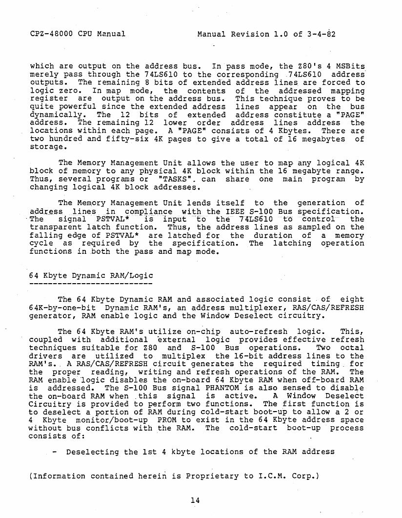
which are output on the address bus. In pass mode, the zao's 4 MSBitsmerely pass through the 74L86l0 to the corresponding ,74L86l0 addressoutputs. The remaining 8 bits of extend~d address lines are forced tologic zero. In map mode, the contents of the addressed mappingregister are output on the address bus. This technique proves to bequite powerful since the extended address lines appear on the busdynamically. The 12 bits of extended address constitute a "PAGE"address. The remaining 12 lower order address lines address thelocations within each page. A "PAGE" consists of 4 Kbytes. There aretwo hundred and fifty-six 4K pages to give a total of 16 megabytes ofstorage.
The Memory Management Unit allows the user to map, any logical 4Kblock of memory to any physical 4K block within the 16 megabyte range.Thus, several programs or "TASKS". can share one main program bychanging logical 4K block addresses.
The Memory Management Unit lends itself to the generation ofa9dtJ~ss lines in 90mpliangewith thE:~EEES-I00 BU::; specification.
"The signal PSTVAL* is input "to the" 74LS610 to control thetransparent latch function. Thus, the address lines as sampled on thefalling edge of PSTVAL* are latched for the duration of a memorycycle as required by the specification. The latching ~peration
functions in "both the pass and map mode.
64 Kbyte Dynamic RAM/Logic
The 64 Kbyte Dynamic RAM and associated logic consist of eight64K-by-one-bit Dynamic RAM's, an address multiplexer, RAS/CAS/REFRE8Hgenerator, RAM enable logic and the Window Deselect circuitry.
The 64 Kbyte RAM's utilize on-chip auto-refresh logic. This,coupled with additional external logic provides effective refreshtechniques suitable for zao and 8-100 Bus operations. Two octaldrivers are utilized to multiplex the l6-bit address lines to theRAM's •. A RA8/CAS/REFRESH circuit generates the required timing. forthe proper reading, writing and refresh operations of the RAM. TheRAM enable" 'logic disables the on-board 64 Kbyte RAM when off-board RAMis addressed. The 8-100 Bus signal PHANTOM is also sensed to disablethe on-board RAM when .this signal is active. A Window DeselectCircuitry is provided to perform two functions. The first function isto deselect a portion of RAM during cold-start boot-up to allow a 2 or4 Kbyte monitor/boot-up PROM to exist in the 64 Kbyte address spacewithout bus conflicts with the RAM. The cold-start boot-up processconsists of:
Deselecting the 1st 4 kbyte locations of the RAM address
(Information contained hereiri is Proprietary to I.C.M.Corp.)
14

CPZ-48000 CPU Manual Manual Revision 1.0 of 3-4-82
space.Deselecting all of RAM through commands from the EPROM.Relocating the EPROM address to the upper 8K locations of theaddress space through commands from the EPROM.Re-enabling all of RAM except the area in which the EPROMexists (EOOO~EFFF).
Performing the Operating System load process.At completion of the Operating System load process,deselecting the EPROM through commands loaded in the RAM &enabling all of RA}1.
The second function is to deselect a "Window" of RAM asspecified under software commands. This "Window" is defined as asection of memory which is enabled or disabled under software control.The window boundaries are specified by the contents of two four-bitregisters. One register holds the lower boundary and the. other holdsthe upper boundary. The values of the register can take on any valuefrom O(hex) to F(hex). In this manner, any window commencing andending at any 4 Kbyte boundary may be specified. This feature enablesthe user to configure multi-user bank select architectures using bankselectable memory boards installed in the S-lOO Bus. The feature alsoenables the user to configure systems where an external memory, suchas a memory mapped video board, is required to co-exist in the 64Kbyte address space with the on-board RAM.
2K/4K EPROM
The CPZ-48000 may accommodate either a 2K (2716) or 4K (2732).EPROM. A jumper (jumper JB) is made available to select either of thetwo EPROM types. The EPROI·l functions as both a boot-up and a moni torPROM. As a boot-up PROM, the EPROM contains the software routinesnecessary to manipulate the Window Deselect Circuitry and to load therequired Disk Operating System contained on Floppy Disk Drivediskettes. The EPROM also contains monitor routines which arediscussed in the SOFTWARE/PROM MONITOR sections.
~/O Chip Select Logic
The I/O Chip Select logic generates the "chip select" signalsfor the SID, PIO, programmable counter, universal interruptcontroller, FDC, Memory Management Unit (MMU), Boot/Monitor Enable,Memory Deselect Logic, FDC Configuration register and the DMACont~oller. In addition, the required control and data signals aregenerated for the SID, FDC and PIO. Because the SIO, FDC and PIO maybe operated under DMA control (as well as programmed I/O), the chip
(Informatio~ contained herein is Proprietary to I.C.M. Corp.)
15

CPZ-48000 CPU Manual Manual Revision 1.0 of 3-4-82
select, control and data _signals are generated to handle each casewithin this logic.
POWER-ON CLEAR/RESET LOGIC
'This logic provides reset signals to the CPU as well as to the5-100 Bus interface. The logic is activated under two conditions,when power is first applied to the board, and when the S-lOO Bussignal RESET* is activated.
Signals asserted upon applying power are:
a. S-IOO Bus signals POC*, RESET*, and SLAVE C~R*
b. Internal CPZ-48000 reset
Signals assered when RESET* is asserted are:
a. S;;':TO'OBlis' ·sfghaTSLAVE·····CLR*····b. Internal CPZ-4aOOO reset
CLOCK GENERATOR
The clock generator divides an eight-Megahertz crystal~generated
clock signal to provide the· internal CPU clock (OCLK) I the S-IOO Busclocks (0 and CLOCK) and internal clocks BUSCLK and SCLK. These clocksignals are utilized to implement S-IOO Bus signals in conformancewith the IEEE standard for the S-IOO Bus on a well-defined, clocked-
. logic basis.
CPU-Control Signals Generator
The CPZ-48000 architecture is enhanced by us~ of state-of-the~rt LSI components. The board utilizes a m1X of Z80 supportcomponents (SIO and PIO) and 8080 support- devices (8253, 9519A and95l7A). A variety of logical conflicts arise due to the differingrequirements of these components and those of the 5-100 control bus.Further, the control signals generated by the DMA Controller differfrom ZaG-type control signals. It is the function of the CONTROLSIGNALS GENERATOR to generate all of the appropriate control signalsrequired by each of these components and the S-IOO BUS CONTROL SIGNALSGENERATOR (described below).
(Informatioi contained herein is Proprietary to I.C.M. Corp.)
16

CPZ-48000 CPU Manual
S-IOO BUS CONTROL SIGNALS GENERATOR
Manual Revision 1.0 of 3-4-82
The S-100 Bus Control Signals Generator consists of the logicnecessary to generate key 8-100 Bus signals such as p8YNC, pSTVAL~,
pWR*, and pDBIN.
p8TVAL* is of particular importance, as this signal is used toto perform a tra~sparent latch function for other signals, the resultof which-is to generate 8-100 Bus signals in conformance with the IEEEtiming standards. Address and data lines are latched with this signalwhereby status is latched or unlatched as selected by a jumper. Whilein the latched mode, the CPZ-48000 is set for full IEEE timingconformance. The transparent mode enables .systems to operate inconformance with zaD timing.
Jumper option JC is provided to configure pDBIN to any given. system which may not tolerate the stringent IEEE timing requirementsfor this signal. Read access time can be adjusted by selecting one ofthe two positions on the header.
5-100 Bus Interface
The 8-100 Bus consists of 100 electrical signal lines. Theseare grouped into sets of lines used to transmit data and control among
-interconnected devices. The groups are:
Group No~ of Lines
Address Bus 24.Input Data Bus 8Output Data Bus 8Status Bus 8Control Input Bus 5Control Output Bus 6DMA Control Bus 8Vectored Interrupt Bus 8Utility Bus 8System Power 9Manufacturer specified lines 3Reserved lines 5
Devices connected on the bus are classified as either busmasters or bus slaves and as either permanent or temporary masters.The CPZ-48000 is a permanent bus master. Any other master connectedto the 8-100 bus may take control of the bus by making the appropriate
(Information contained herein is Proprietary to I.C.M.Corp.)
17

CPZ-48000 CPU Manual Manual Revision 1.0 of 3-4-82
DMA request provided no internal DMA by the SIO, FDC, 'or PIO is inprogress. If the DMA controller is programmed for fixed priorityoperation then the 8-100 Bus DMArequest will be honored first ifsimultaneous DMA requests occur.
Each of the S-IOO Bus signalsdescribed on the following pages.is included in Appendix B.
Address.Bus
utilized by the CPZ-48000 areA summary of the S-IOO Bus signals
The address bus consists of 24 lines used to select a memorylocation or an input/output device during a bus cycle. All 24 linesare active during a memory read, write or opcode fetch (MI) cycleunless the Memory Management Unit has been programmed for pass mode inwhich case the uppermost 8 bits (A16-A23) are forced to logic zero.Theleast$ign.ifiC:_~I1tpyteC>._f'thea¢lgress Jines i~ a<::t~ye for iI1.I?utor
·output cycles. Address bus lines are enabled while -ADSB* is inactive(no S-IOO Bus- DMA cycle fn progress). The address bus lines aredenoted as AO through A23, with line AO representing the leastsignificant" bi t. Line.s AO through A7 compromise the least sig.nificantbyte and line.s A8 through AIS make up the "high" address byte withbits A16 through A23 constituting the extended address byte. Two
.octal-drivers and the Memory Management Unit are used to condition thelines in conformance with the characteristics requi~ed by the IEEE S100 Bus standard.
Input Data Bus
There are eight input data lines which are enabled onto the CPUdata bus when the enabling signal DIEN* is active. This signal isactive under the following conditions:
1. .AN EXTERNAL I/O CYCLE IS INITIATED.2 •. AN EXTERNAL MEMORY CYCLE IS INITIATED.3~ AN EXTERNAL DEVICE INTERRUPTS THE CPU
AND PLACES A VECTOR ON THE DATA BUS.
(Information contained herein is Proprietary to I.C.M.Corp.)
18

CPZ-4800a CPU Manual
Output Data Bus
Manual Revision 1.0 of 3-4-82
There are eight data output lines which are enabled by thesignal DODSB*. A line driver conditions these lines to conform withthe IEEE S-IOO Bus standard.
Output Data Bus lines are designated DOa through D07, with ·lineDOO representing the least significant bit.
Status Bus
The status bus consists of eight output lines· which define thecurrent CPU bus cycle type. Seven of the eight lines defined in theS-lOO Bus speCification are utilized by the CPZ-48000. These linesare enabled while the enabling signal SDSB* is inactive. Statussignals may be selected for full IEEE timing performance (latchedciode) or·~for zao timing (tr~sparent). This selection is made throughjumper option JI. An octal latch/line driver is used to condition alllines of the Status Bus in conformance with the IEEE 5-100 Busstandard. ·The seven lines of the Status Bus are:
Status
sMEMRsMIsINPsOUTsWO*sINTAsHLTA
Function
Memory ReadOpcode FetchInputOutputWrite cycleInterrupt acknowledgeHalt acknowledge
The status signal SXTRQ* (16-bit data transfer request) is notused in the CPZ-48000 and is left open. The remaining Status Buslines ~re described in the following paragraphs.
sMEMR (Memory Read)
sMEMR is a status signal indicating that a memory read cycle isin progress. This signal is valid during a normal memory read cycle(memory read or opcode fetch cycle).
(Information contained herein is Proprietary to I.C.M. Corp.)
19

CPZ-48000 CPU Manual
sMl (Opcode Fetch)
Manual Revision 1.0 of 3-4-82
sMl is a statuE~ signal indicating that a memory read/opcodefetch cycle is in progress.
sINP (Input)
SINP is a status signal indicating that a peripheral device readcycle is in progress.
sOUT (Output)
soUTO-is a status signal -indicating that- a peripheral devicewrite cycle is in progress.
sWO* (Write Cycle)
SWO* is a status signal indicating that a write cycle is inprogress, wherein data is transferred from an 8-100 Bus master to aslave.
sINTA (Interrupt Acknowledge)
sINTA is a status signal indicatingacknowledge cycle is in progress.
sHLTA (Halt Acknowledge)
that an interrupt
sHLTA is a status signal indicating that the CPU is in a haltstate.
(Informatic~ contained herein is Proprietary to I.e.M. Corp.)
20

CPZ-48000 CPU Manual
Control Input Bus
Manual Revision 1.0 of 3-4-82
The Control Input Bus consists of six signals, five of which areused in the CPZ-48000. These lines allow 8-100 Bus slaves tosynchronize the CPZ-48000 with conditions internal to the bus slave,to request the relinquishment of the S-lOO Bus (DMA request) and todisable the CPU from the S-lOO Bus. The signals are conditioned bypull-up resistors and Schmitt-trigger input receivers.
The five lines of the Control Input Bus are:
Line
XRDYINT*NMI*HOLD*
Function
Slave readySpecial readyMaskable interrupt requestNon-maskable interrupt requestDMA request
These lines are described in the following paragraphs.
ROY (Slave Ready)
This control line is used by 8-100 Bus slaves to suspend buscycles by inserting wait states ~n a CPU cycle. Slaves may connect tothis line by using an open-collector driver.
XRDY (Special Ready)----------------~---
This control line is used as a special ready line to accommodatedevices such as front panels. Only one slave device should connect~nto the XRDY line. This line also suspends bus cycles by introducingwait states to the cpu.
INT* (Maskable Int. Req.)
This control line is used to request service from the CPU on aninterrupt basis. The INT* line is enabled (unmasked) or disabled(masked) under software control. When the INT* line is activated, theCPU responds with an acknowledge signal and subsequently gates the
(Informatiod contained herein is Proprietary to I.C.M. Corp.)
21

CPZ-48000 CPU Manual Manual Revision 1.0 of 3-4-82
opcode or vector information asserted on the bus by 'the bus slave.initiating the interrupt. Interrupt may be asserted'on the INT* lineby the SIO, PIO or the 95l9A interrupt controller. Logic is prOVidedto sense these conditions and to respond appropriately. INT* shouldbe asserted as a continuous level and held active until a response isreceived.
NMI* (Non-maskable Int. Req.)
This control line is used to request service from the CPU on aninterrupt basis. The NMI* is non-maskable, meaning it is alwaysenabled. When an interrupt occurs on NMI*, a CPU acknowledge cycle isnot generated.
Normally, only critical signals are connected to the NMI* line.The CPZ-48000 provides the option to connect the 8-100 Bus signalPWRFAIL*to .the NMI* line via a jumper option. NMI* is sensed on a
'signal edge transition.
HOLD* (DMA Request)
This control line is used by 5-100 temporary bus masters torequest control of the 8-100 Bus from the CPZ-48000. This line maybe disabled under software control through the 9517A controller. When'enabled, a DMA cycle may be initiated by asserting this line. The9517A DMA controller will respond with the signal pHLDA when the cycleis initiated, and will relinquish control to the temporary bus master.
Control Output Bus
The control output bus consists of six lines, one of which isoptional. These lines are enabled when the enabling signal CD8B* isin~~tive•. A line driver is used to condition these lines to conformwith'the ch'aracteristics required by the IEEE 8-100 Bus standard.
(Information contained herein is Proprietary to I.C.M.Corp.)
22

CPZ-48000 CPU Manual Manual Revision 1.0 of 3-4-82
The six lines of the Control Output Bus are:
Line
pSYNCpSTVAL*pDBINpWR*pHLDApWAIT
Function
Cycle startStatus validRead strobeWrite strobeHold acknowledgeWai t (Optional)
These lines are described in the following paragraphs.
pSYNC (Cycle Start)
pSYNC i.s a control signal which indicates the start of a new buscycle. The signal becomes active when an I/O cycle, memory cycle, DMA
"read or DMA write cycle occurs. The signal remains active forapproximately one bus clock in accordance with the IEEE S-lOO Busstandard. pSYNC does not become active during a refresh cycle.
pSTVAL* (Status Valid)
pSTVAL* is a control signal which indicates that address, Data-and Status signals have stabilized on the bus during the current buscycle. It becomes active on-the first CPU clock cycle after pSYNCbecomes active, and goes inactive on the first CPU clock cycle afterthe bus cycle is complete. By using this signal as the latchingsignal, the address, data, and status signal timing will conform tothe timing specified in the IEEE standard.
pDBIN (Read Strobe)
-pDBI~ is a control signal which gates data arriving on the CPUdata bus from an external source. Header jumper option JC is providedto specify the pulse width and timing for this signal. Two optionsare available:
a. FULL IEEE TIMING CONFOR~~NCE: In this option, pDBIN goesactive at a specified time after pSTVAL* goes active.This presents the smallest read access time windowavailable. A single clock cycle duration is typical.
(Information contained herein is Proprietaiy to I.e.M. -Corp.)
23

CPZ-48000 CPU Manual Manual Revision 1.0 of 3-4-82
b. ZaD TIMING: In this option, pDBIN goes active whenthe zao read signal goes active, thereby giving. the usera maximum read access time window. This is typicallyone and one-half clock cycles in duration.
pWR* (Write Strobe)
pWR* is a control signal which performs the function of a writestrobe to write data from the CPU data bus to an addressed peripheralor memory device. pWR* goes active at the specified time after pSTVALgoes active for I/O write cycles, DMA memory write cycles and CPUmemory write cycles.
pHLDA (Hold Acknowledge)
pHLDA is a control signalwhfch fs actIve when the CPZ~4aOOO
relinquishes the address, data, control and status buses in responseto a temporary master DMA request. This signal is generated by the95l7A Dt1A controller, channel 0 DMA acknowledge output.
pWAIT (Wait [optional])
pWAIT is ·a control signal which is active when any waitcondition is active within the CPZ-48000. Thus, pWAIT goes activewhen either of the two 5-100 Bus wait lines (RDY or XRDY) go active,the FDC programmed I/O wait state generator goes active or when the95l9A interrupt controller "pause" signal goes active (indicating thatan interrupt cycle is in progress and the daisy chain priority isbeing resolved). pWAIT is optional and may be connected ordisconnected via a jumper option. pWAIT is not a signal required bythe IEEE 5-100 Bus standard.
DMA Control Bus
The DMA Control Bus consists of eight input lines. Four ofthese are activated as required for the permanent bus master. Theremaining four lines are utilized to isolate the CPU from the 5-100when the permanent bus master relinquishes control to the temporarybus master. The disable lines are connected to schmitt-trigger inputreceivers to provide noise immunity. The conditioned signals thendisable the respective output line drivers. The DMA arbitration lines
(Informatiol contained herein is Proprietary to I.C.M. Corp.)
24

CPZ-48000 CPU Manual Manual Revision 1.0 of 3-4-82
are used by the temporary masters to determine which temporary masterhas the use of the bus during a DMA cycle. The permanent bus masterneed not arbitrate. The eight DMA Control Bus lines are:
Line Function
DMAO*DMAl* 'DMA2*DMA3*ADSB*DODSB*SDSB*CDSB*
DMA¥arbitration lineDMA arbitration lineDMA arbitration lineDMA arbitration lineAddress disableData out disableStatus disableControl output disable
Vector Interrupt Bus
The Vectored Interrupt Bus consists of eight lines, designatedVIO* through V17*. VIO* is treated as the highest priority interruptline. These lines should be asserted as levels, and should remainasserted until a response is received.
The Vectored Interrupt Bus lines are connected to interruptoption jumpers to connect the appropriate lines to the 95l9A interruptcontroller. This device then masks or unmasks the interrupts,priori tizes the requests, and' asserts the INT* signal. to the .cpu.
utility Bus
The Utility Bus consists of eight lines. Output lines areconditioned by drivers to conform with characteristics required by theIEEE' S-IOO Bus standard. The eight Utility Bus lines are:
Line
<p (clock)CLOCK~lWRITE
POC*SLAVE CLR*RESET*
Function
System clock (output)Clock (output)Memory write strobe (output)Power-on clear (output)Slave clear (output)Reset (input/output)
Each of these Utility Bus signals are described in the followingpara~raphs.
(Informatio~containedherein is Proprietary to I.C.M. Corp.)
25

CPZ-48000 CPU Manual
~ (System Clock)
Manual Revision 1.0 of 3-4-82
~ is the 5-100 Bus system clock. ~ has the same sense as theinverted CPU computer clock (BCLK).
CLOCK (Clock)
CLOCK is a 2 Megahertz Utility clock signal to be used by slavedevices.
MWRITE .(Memory wri te)
This Tine ·isoptional 'on the CPZ ....48000~ It· may be connected tothe bus via jumper option JD, or this signal may be generatedexternally to the CPZ-48000, in which case the jumper would beomitted.
Logic is provided so that ~MRITE is generated by either CPZ48000 on-board signals (pWR* & sOUT) or by off-board signals if thestatus and control bus drivers are disabled. This signal is activeduring DMA and CPU memory write cycles.
*~* N 0 T.E ***
Care must be taken that the signal is generated at only onepoint in the system.
POC* (Power-on Clear)
-the POC* line is active when initi~1 power-up occurs on th~ 5100 ·Bus. 'When POC* is active, SLAVE CLR* and RESET* are asserted.POC* is guaranteed to stay active for at· least 50 milliseconds.
SLAVE CLR* (Slave Clear)
SLAVE CLR* is the signal line which resets all slave devices onthe S-IOO bus. During power-on clear, this line is asserted by theCPZ-48000 power-on clear logic. External devices may assert RESET*
(Information contained hereirl is Proprietary to I.C.M.Corp.)
26
CPZ-48000 CPU Manual Manual Revision 1.0 of 3-4-82
and, in doing so, assert SLAVE CLR* as well. RESET*.is driven by anopen-collector driver.
ERROR* (Error)
Error* is a signal generated bya slave device to indicateabnormal conditions such as parity error, CRC error, out of tape,. etc.This line is connected to a jumper option where it may be selected asan inte~rupt source.
PWRFAIL* (Power Failure)
FNP~AIL* is a signal generated external to the CPZ-48000 toindicate that a power failure has occurred. This signal remainsactive until ~ower is restored and POC* is active. The signal is
. available to the user via a jumper so that it may be connected to theNMI* line of the cpu.
System Power.
The system power lines consist of all lines supplyingunregulated power to the CPZ-48000 and other devices connected to the·S-IOO Bus. The nine System Power lines are:
Lines Quantity
+8 VOLTS 2+16 VOLTS 1-16 VOLTS 1GOO 5
The +8 VOLT lines are connected to a +5 VDC regulator to supply+5 volt of regulated power to the CPZ-48000 •
. The +16 VOLT connects to a +12 VDC regulator and the t~NO serialport connectors. The -16 VDC line connects to the two serial portconnectors. The 16 volt lines are utilized on the serial ports forsupplying power to RS-232C driver circuitry.
All ground lines are connected to the ground plane to provide alow impedance path from the S-lOO Bus ground to the CPZ-48000 ground.
(Information contained herein is Proprietary to I.C.M.Corp.)
27

CPZ-48000 CPU Manual
MANUFACTURER SPECIFIED LINES
Manual Revision 1.0 of 3-4-82
The IEEE S-IOO ~Bus standard reserves three of the 100 lines forspecial use. by the manufacturer. The CPZ-4aOOO utilizes these lines.Two of these are required to implement the oaisy chained priorityinterrupt expansion. The third supplies the zao refresh signal.
~l lines may be connected through solder jumpers. See thesection on Solder/Trace Cut Options.
The three Manufacturer specified lines are described in thefollowing paragraphs.
IPROCESS* (Interrupt in Progress)
IPROCE88* is a bi-directional signal which indicates that aninterrupt cycle is in process. This line is required to cascadeexternal 9519A Universal Interrupt Controllers. IPROCE8S* utilizespin 65 of the S-lOO Bus.
PCHAIN (Interrupt Priority)
PCHAIN is an output signal which indicates the priority level ofthe interrupt in progress. If it is high, the interrupt responseaction is passed to the next interrupt device in the serial interruptstructure. PCHAIN utilizes pin 21 of the 8-100 Bus.
RF8H* {Refresh)
RF8H* is the Z8D refresh signal buffered for use b~7 external.dynamic RAM memory devices connected to the S-lOO Bus.
Reserved Lines
Five of the 8-100 Bus lines are reserved for future use by theIEEE specification. The CPZ-48000 makes no connection to these lines.
(Informatiof contained herein is Proprietary to I.C.M. Corp.)
28

CPZ-48000 CPU Manual Manual Revision 1.0 of 3-4-82
**** OPERATING INSTRUCTIONS ****Instructions are given herein to configure the CPZ-48000 from
both the hardware and software standpoint. The user will be pleasedto find that minimal setup procedures are required.
HARDWARE SETUP INSTRUCTIONS
The hardware is configured v~a jumper options and solder/tracecut areas. The solder/trace cut areas are referred to as PJX, where Xis the area designator. These jumpers are by nature rarelyreconfigured. PJX options are located on the "solder" side of theboard. The jumper options referred to as JX, where X is the jumperdesignator, gives the user flexibility in setting up the CPZ-48000 fora multitude of applications. Jumper options are located on the"component" side of the board. Instructions are also included onconnecting the personality boards to the CPZ-48000.
JUMPER OPTIONS
Refer to figure 1 to locate the JX header positions.jumper blocks are listed as ~ollows:
JA - FLOPPY DISK CONTROLLER CLOCK SELECTJB EPROM SELECTJC - INTERRUPT SIGNAL SOURCE SELECTJD - CONNECT "MWRITE" TO 8-100 BUSJE - IEEE/Z80 TIMING SELECTJF - S-IOO BUS STATUS (IEEE or TRANSPARENT SELECT)
JA
The JX
The FDC requires a 2Mhz clock when operating with 8-inch drivesand a IMhz clock when operating with S-1/4-inch drives. To select the2Mhz clock, set the jumper provided to position 2~ • To select theIMhz clock, set the jumper provided to position 3-2.
[ JA ] block+---+
1 I 0 I 2 MHz2 I 0 I3 I 0 I 1 MHz
+---+
(Informatio~ contained herein is Proprietary to I.C.M. Corp.)
29
CPZ-48000 CPU Manual
JB
Manual Revision 1.0 of 3-4-82
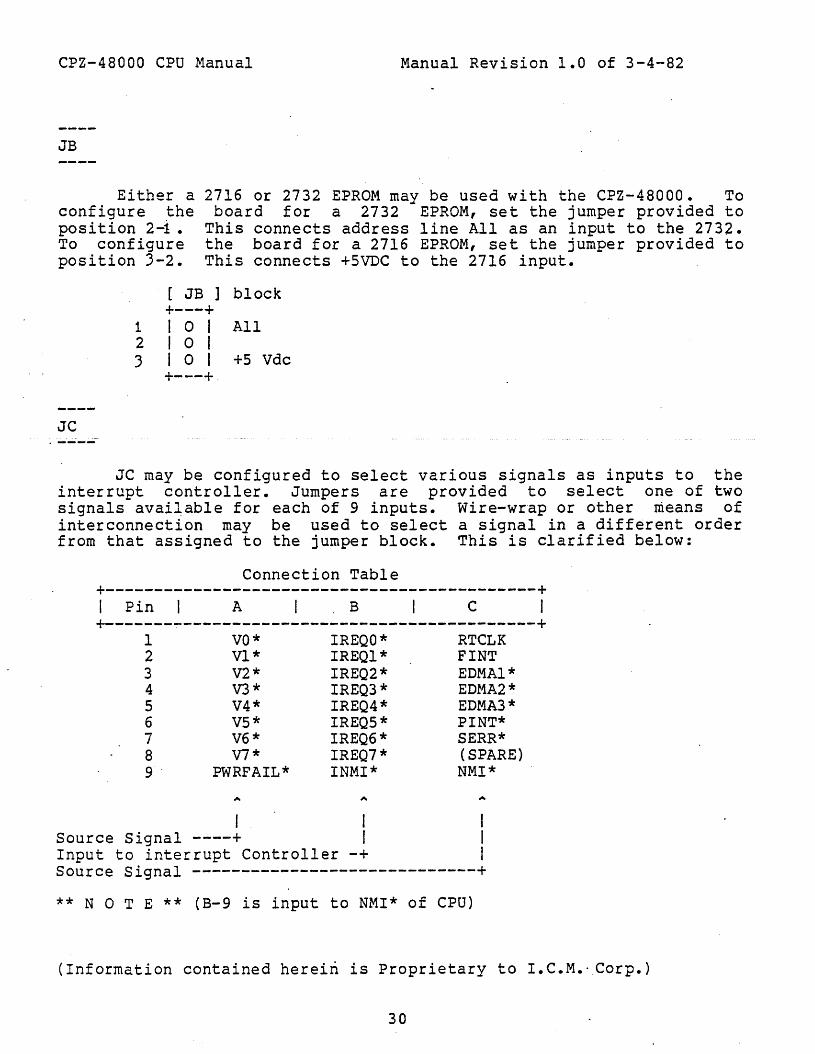
Either aconfigure theposition 2-1 •To configureposition 3-2.
2716 or 2732 EPROM may be used with the CPZ-48000. Toboard for a 2732 EPROM, set the jumper provided to
This connects address line All as an input to the 2732.the board for a 2716 EPROM, set the jumper provided toThis connects +5VDC to the 2716 input.
[ JB ] block+---+
1 I 0 I All2 I 0 I3 I 0 I +5 Vdc
+---+
JC
JC may be configured to select various signals as inputs to theinterrupt controller. Jumpers are provided to select one of twosignals avai~able for each of 9 inputs. Wire-wrap or other ~eans ofinterconnection may be used to select a signal in a different orderfrom that assigned to the jumper block. This is clarified below:
Connection Table+--------------------------------------------+I Pin I A I B I c I+-------~------------------------------------+
1 VO* IREQO* RTCLK2 Vl* IREQl* FINT3 V2* IREQ2* EDMAl*4 V3 * IREQ3 * EDMA2 *5 V4* IREQ4* EDMA3*6 V5* IREQ5* PINT*7 V6* IREQ6* SERR*8 V7* IREQ7* (SPARE)9" PWRFAIL* INMI* NMI*
I ISource Signal ----+ IInput to interrupt Controller -+ ISource Signal -----------------------------+** NOT E ** (B-9 is input to NMI* of CPU)
(Information contained hereiri is Proprietary to I.C.M.·Corp.)
30

CPZ-48000 CPU Manual
[ JC ] block+-----------~-----+1010101010101010101 c+-----------------+1010101010101010101 B
+-----------------+1010101010101010101 A·
+-----------------+123 4 567 8 9
EXAMPLES:
Manual Revision.l.O of 3-4-82
1) To connect 5-100 Bus Vector line V5* to the interruptcontroller, install a jumper from position ~6 to B6.
2) To ·connect Floppy interrupt signal FINT* to the interruptcontroller, ~nstall a jumper from C2 to B2.
·3) To connect the parallel port interrupt line to the highestpriority interrupt input (IREQO), install wire-wrap or anyother adequate interconnection means from C6 to 81.
**** NOT E ****
a.) Highest priority input is IREQ a and the lowest is IREQ 7.b.) NMI and PWRFAIL are sources to the CPU non-maskaole
interrupt input.c.) Signal source definition are as follows:
VxPWRFAILRTCLKFINTEDMAXPINTSERRNMI
----JD
= 5-100 Bus vectored interrupt (X ; 0 --> 7)= S-IOO Bus power fail= Real Time Clock= Floppy interrupt= Channel X end of DMA process (X = 1 --) 3}= Parallel port interrupt~ 5-100 Bus error= 5-100 Bus non-maskable interrupt
The CPZ-48000 may be configured to output S-IOO Bus signals in70mpliance w~~h the IEEE specifications for the 5-100 Bus timing, orlt may be conrlgured to output the bus signals in zao mode. The~election .i~ made via jumpers ~D and JF. To select IEEE timing,Jumper posltlon 2-3 of JD. To select ZaOA timing, jumper position 1-2of JD.
(Information contained herein is Proprietary to I.e.M. Corp.)

CPZ-48000 CPU Manual
[ JD ] block+---+
3 I 0 I IEEE2 I 0 II I 0 I Z80
+---+
JE
M~nual Revision 1.0 of 3-4-82
The signal "MWRITE" may be generated on the CPZ-48000 or it maybe generated from signals external to the CPZ-48000 like a frontpanel.- In ~ny case, the signal should be sourced by one device only.If the CPZ-48000 is to be the source of the signal, install the jumperprovided on jumper block JEt otherwise, leave the jumper off.
[ JE ] block+-+I I101I II I101I I+-+
JF
The 5-100 Bus status signals may be output from the CPZ-48000 inlatched mode which makes timing conform to the IEEE specification ormay be output in transparent mode which makes the timing correspond tothat of the Z80. To select zao timing, jumper position 2-3 of JF. To'select IEEE timing, jumper position 1-2 of JF.
[ JF ] block+---+
3 I 0 I Transparent2 I 0 I1 I 0 I Latched
+---+
(Information'contained herein is Proprietary to I.C.M. Corp.)

FOC CLOC K SELECT
INTERRUPT SOURCE SELECT SELECT REAOTIMING
SOURCE MWRITE SELECT STATUS TIMING
FIGURE 1
JUMPEF~ OPTIONS

CPZ-48000 CPU Manual Manual Revision 1.0 of 3-4-82
SOLDER/TRACE CUT OPTIONS
Refer to figure 2 to locate the PJX solder/trace options. ThePJX options are listed as follows:
PJA - SID PORT A clock source selectPJB - SID PORT B clock source selectPJC - CONNECT INTERRUPT IN PROCESS to S-IOO BusPJD - CONNECT INTERRUPT PRIORITY CHAIN to S-IOO BusPJE - CONNECT Z80 REFRESH to S-IOO BusPJF - CONNECT S-IOO Bus GROU~~ to PCB ground plane
PJA
The cPz-4aOOO comes configureds6 that the SIO ports receivetheir baud rate clocks from an on-board programmable timer. The boardcould be reconfigured to source the clocks from the SIO serial portconnectors. Such is the case when synchronous modems connect to theserial ports.. The modem provides a clock to the SIO. Furthermore,the modem may receive the clock from the on-board timer, condition theclock and return it to the input of the SIO. The transmit and receiveclocks may be sourced separately on Port A. All combinations are.possible through this jumper.
To source SIO PORT A inputs from the SID connector only, cut thetrace from PJA 'a' to PJA 'bl. The source can now be -connectedthrough the personality board on either PIN P2-2 or P2-3.
If the SIO PORT A inputs are to be sourced separately from theSIO connector, cut the trace from PJA b to PJA c. The receive clockis now input on P2-3 and the transmit clock is input on P2-2.
[ PJA ] area
A BTimer -)----0--0---> Receive Input clockclock I .
0---> Transmit Input clockC
(Information contained hereiri is Proprietary to I.e.M. Corp.)
33

CPZ-48000 CPU Manual
PJB
Manual Revision 1.0 of 3-4-82
To source SIO Port B input from the SIC connector only, cut thetrace at PJB. The source can now be connected through the personalityboard on pin P3-3.
[ PJB ] area
Timer -)----0--0-----) Receive/Transmit input clo.ckclock
PJC
The CPZ-48000 may connect to off-board devices with priority-interrupt structures which comply with the Advanced Micro DigitalUniversal Interrupt Controller AM9519A method of resolving interruptpriority level. The method consists of serially chaining interruptdevices via a signal referred to as "PCHAIN" and connecting inparallel the signal "IPROCESS". The CPZ-48000 is factory c6nfiguredso that both these signals are NOT connected to the 5-100 Bus. Soldera jumper in PJC if the interrupt structure is to be extended to otherboards outside of the CPZ-48000.
[ PJC ] area PI+//+I I
IPROCESS -)-------0 0------16511 1+//+
PJD
See- PJC.
Solder a jumper in PJD if the interrupt structure is to beextended to other boards outside of the CPZ-48000.
[ PJD ] area PI+//+1 1
PCHAIN -)-------0 0------1211I 1+//+
(Information contained herein is Proprietary to I.C.M.Corp.)
34

CPZ-48000 CPU Manual
PJE
Manual Revision 1.0 of 3-4-82
If the 8-100 Bus dynamic RAM memory boards require the Z80refresh signal for~roper operation, PJE may be connected to providethat signal •.
[ PJE ] area PI+//+I I
RFSH* -)--------0 0------1661I 1+//+
PJF
Some 8-100 Bus boards utilize pin 20, 53, and 70 for signalsother . than ground. The IEEE specification requires that these beconnected to ground. If a board is installed in the bus and any ofthese pins are used for other than ground, the corresponding traces atPJF must be cut.
[ PJF ] area. PI+//+I 1
+----0--0------12011 I 1
+---+----0--0------15311 I 1 1V +----0--0------1701
GND I 1+//+
(Informatic~ contained herein is Proprietary to I.C.M. Corp.)
35

.Oume Datatrack 8 jumper options
DriveDesiginator
CDDC2S
-OSI. DS2
OS)OS4
T40HAYDLDS
SHUNT
ABXRIZHL
DriveOption
closedopenopenop.en
drive select for Adrive select for Bdrive select for Cdrive select for 0
openopenclosedopenclosed
closedclosedopen·closedclosedopenopen
} we trLut the drive .:is} one Lig drive for acuLl(
sidc a 01:' era t ion.
All other drive jumpers are lett as is it"um thL factury.
35-A

GROUND FOG TEST
SK) PORT A CLOCK SELECT SIO PORT B CLOCK SELECT
F I(JURE 2
SQLPER/TRACE CUT
, OPTIONS
'"--__J~
~_=-==---=- HCONNECT PWAIT
TO BUS
CONNECT PRIORITYCHAIN TO BUS
DISCONNECT GROUND,
TO PINS 20 tl 70 OF BUS
_," ~,." RN7 Po. JE".- -,- tlllU.llll~ ....~.
CONNECT INTERRUPT-INPROCESS TO BUS
U19 U12 C17 c::J
t-..J.J'-----' '--- I§ I§ 'l::l I P I '--§__--l '--__
C1oc::::J U20 U21 U22 c:::l C20
'------']piE Ie=-----:=J PL-__U29 C::l C22LOO U31 U32
DISCONNECT GROUN D
TO PIN 53 OF BUS
CONNECT REFRESH TO BUS 6""-----~----+-.--~ =--......§==--=--=-.-..,,-L-----IJ... MODEL "\
rrw--....-r~'----,..,PJ - "--_-J - ----I 117 CPZ-4IClIOO
~--- IT U5 ='2~ = J6 U~ II...----.: :,---~. IE ]i

CPZ-48000 CPU Manual Manual Revision 1.0 of 3-4-82
PERSON~LITY BOARD INTR~CONNECTION INSTRUCTIONS
The CPZ-48000 has four connectors at the top of the boardnumbered Jl through J4. These are listed below:
Jl - FDC ConnectorJ2 - SIO Port A ConnectorJ3 - SIO Port B ConnectorJ4 - PIa Connector
These are typically connected to peripheral devices throughpersonality boards which are small printed circuit boards customizingthe above listed devices to a variety of peripherals.
Most S-lOO Bus chassis provide a jumper plate at tne rear of thechassis to which peripheral connectors are installed. Typically, theconnectors are of the ITT CANNON DB25 type. The personality boards
·provided by ICM are boards with DB25 connectors at one end and headerplug connectors at the other. The DB25 connector end is to beinstalled in the cutouts provided on the connector plate. Flat ribboncable then connects the CPZ-48000 connector to the personality board.See figure 3 showing a personality board installation.
The FDC personality boards are provided with connector adapters.These adapters reconfigure the connection from DB25 type connectors to.header plug or edge card type connectors to provide a means for the'user to utilize standard controller to drive cables. See figure 4showing the addition of a connector adapter.
At a minimum, the FDC and SIO Port B"personality boards must beinstalled. The instructions follow:
1.- Select a DB25 connector cutout at the rear of the chassisfor the FDC personality board.
2.- Insert and hold the FDC personality board in the cutout.·External to the chassis, plug in the desired connector
. adaptor and hold in place.3.- Install #6 nuts, washers and bolts passing the bolts
through the connector adapter and through the personalityboard's DB25 connector.
4.- Install the flat ribbon cable provided at the personalityboard and at the CPZ-48000, connector Jl.
5.- Follow the above procedure, except that an adapter is notused, for the SIO Port B personality board.
6.- Install cables from the chassis connectors to therespective peripherals.
(Information contained herein is Proprietary to I.C.M. Corp.)

CPZ-48000 CPU Manual Manual Revision 1.0 of 3-4-82
**** SOFTWARE SECTION ***
This section of the manual describes the Software Interface forthe CPZ-48000.
PROM Monitor
The CPZ-48000 is shipped with a 2 Kbyte PROM Monitor with basicmemory alter functions, I/O examine functions, Breakpoint facilities,and Disk drive boot function. _The terminal baud rate is sensedautomatically by pushing carriage returns until the PROM monitor signson. Channel B is the main console port, while channel A is theprinter port. Channel A defaults to 9600 baud for the printer. Userprograms may be written to change the baud rate on the fly if needed.Baud- rates supplied for the terminal are as follows:
76800,38400,19200,9600,4800,2400,1200,600,300 baud.
Below is a description of the built.... in Monitor commands andtheir functions. Commands may be either a single letter, singleletter followed by 1, 2 or 3 parameters, or double letter commandsfollowed by 1, 2 or 3 parameters and depends upon the functiondesired.
Basic PROM Commands
*** Note: *** <cr> = carriage return---------------- all entries are in hex.
Register definitionsA=accumulator, F=flags, B=register B, C=register CD=register D, E=register E, H=register HLX=register IX, Y=register IY, P=program counterI=interrupt register, N=interrupt flip-flop
Letter
A
Function
not used
Description
B<cr> Boot disk drive A: Load operating systemon drive A: (CP/M disk)
Cxxxx,yyyy,zzzz<cr> Compare memory Will compare the blockof memory starting withxxxx to yyyy with zzzz.
(Informatic~ contained herein is Proprietary to I.C.M. Corp.)
37

CPZ-48000 CPU Manual Manual Revision 1.0 of 3-4-82
DMxxxx,yyyy>cr> Dump Memory Will display memory fromxxxx to yyyy hex.
DMxxxx,SlOO<cr> .Will dump memory startingat xxxx with a swath of 100.
DR<cr>
E
Display Registers
not used
Will display all Z-80 CPUregisters.
FXXXX,}"Iyy,zz<cr> Fill memory Will fill memory startingat xxxx to yyyy with thehex byte zz.
G<cr> Go command Will execute the programpointed to by the breakpoint PC value withouttrace or breakpoint active.
Gxxxx<cr> Go at address Will set the Program counterto address ...xxxx and beginexecution there.
Gxxxx/yyyy<cr> Go with Breakpoint Begin execution at addressxxxx with a breakpoint ataddress yyyy.
Will display the hex and binarycontents of port xx hex.
Will move the memory contents xxxx to yyyy stating at zzzz.
Will output the byte xx toport yy hex.
Go with Breakpoint Use present Program countervalue to execute until addressyyyy is reached.
Display the hex SUM andDifference of xxxx and yyyy
G/yyyy<cr>
Hxxxx,yyyy<cr> Hex Math
I not usedJ not usedK not usedL not used
~xxxx,yyyy,zzzz<cr>Move memory
N not used
Oyy,xx<cr> Output to port
p not used
Qxx<cr> Query input port
(Informatiol contained herein is Proprietary to I.C.M. Corp.)
38

CPZ-48000 CPU Manual Manual Revision 1.0 of 3-4-82
R<cr>
SMxxxx<cr>
Read disk
Substitute Memory
Will read the oiskette in driveA:, track a sector 1 startinglocation 0000 -hex of memory.
Allows the substitution ofmemory contents starting atxxxx. Carriage return willabort, space bar advances tonext location.
SRx<cr>
T
u
Substitute Register Allows the substitution ofall break p~int register valuesand flags as shown in notes.
not used
not-used
Vxxxx,yyyy,zzzz<cr> Verify memory Allows the verifying of memory·block xxxx to yyyy with thecontents of memory at z-zZ-Z.will display the differences.
W<cr>
x
Y<cr>
Zxxxx,yyyy
Write disk
not u·sed
Display Help Menu
Zero memory
Will write memory contents atlocation 0000 hex of memoryonto the diskette in drive A:
Will display an abbreviated HELPmenu on terminal.
Will zero memory between xxxxand yyyy.
PROM Monitor Display Options
The monitor has several display options which allow the controlof screen dumps and control of listings using a printer. Theseoptions are listed below.
Function Option Description
Memory Dumps Control-SControl-QEsc key
Printer listing - Control-P
(NOTE) Control P option valid
Stops Display scroll.Starts Display scroll.Aborts dump and returns to command level.Enables console dumps to printer.
,This is a toggle function, where a secondcontrol-P will stop printer listing.
only while in the monitor command mode.
(Information contained herein is Proprietary to I.e.M. Corp.)
39

CPZ-48000 CPU Manual,
I/O Port Address Assignments
Manual Revision 1.0 of 3-4-82
The CPZ-48000 uses the.last 128 I/O ports assignment of it's 256I/O port ~ddress space for use with it's on-board peripheral chips.Below is a breakdown of these i/o ports by port function and it~s
corresponding address in hex.
( Serial Port A and B Assignments ]
SIO Port A Data Reg.SIO Port A Control Reg.SIO Port B Data Reg.SIO Port B Control Reg.
[ Floppy Disk Controller Assignment ]
FDC Command/Status Reg.,FDC Track Reg.FDC Sector Reg.FDC Data Reg.
[ Parallel Pqrt A and B Assignment
PIO Port A.Data Reg•.PIO Port A Control Reg.PIO Port B Data Reg.
·PIO Port B Control Reg.
[ Timer Port Assignments ]
Timer Channel 0Timer Channel 1Timer Channel 2Timer Control Reg.
[ Inte~rupt Controller Assignments ]
Interrupt Select Reg.Interrupt Command Reg.
[ Control Registers]
Prom/Boot Reg.Deselect Window Reg.FDC Drive Select Reg.FDC Wait Reg. (program data xfer use)
80 Hex 81 Hex82 Hex83 Hex
90 Hex91 Hex92 Hex93 Hex
AO HexAI HexA2 HexA3 Hex
BO HexBl HexB2 HexB3 Hex
CO HexCl Hex
DO HexDl HexD2 HexD3 Hex
(Information contained hereiri is Proprietary to I.C.M.Corp.)
40

CPZ-48000 CPU Manual Manual Revision 1.0 of 3-4-82
[ Memory 1-1anagement Register.s
MMU Address Reg 1 EO HexMMU Address Reg 2 El HexMMU Address Reg 3 E2 HexMMU Address Reg 4 E3 HexMMU Address Reg 5 E4 HexMMU Address Reg 6 E5 HexMMU Address Reg 7 E6 HexMMU Address Reg 8 E7 HexMMU Address Reg 9 E8 HexMMU Address Reg 10 E9 HexMMU Address Reg 11 EA HexM!wlU Address Reg 12 EB HexMMU Address Reg 13 EC HexMMU Address Reg 14 ED-HexltlMU Address Reg 15 EE HexMMU Address Reg 16 EF Hex
r······Dir-ect· Memory Access Registers
DMA Base/Current Address Reg. 0 FO HexDMA Base/Current Word Count Reg. 0 Fl HexDMA Base/Current Address Reg. 1 F2 HexDl~ Base/Current Word Count Reg. 1 F3 HexDMA Base/Current Address Reg. 2 F4 HexDMA Base/Current Word Count Reg. 2 F5 HexDMA Base/Current Address Reg •. 3 F6 HexDMA Base/Current Word Count Reg. 3 F7 HexDMA Status/Command Register F8 HexDMA write Request Register (software) F9 HexD~~ Write Single Mask Reg. FA HexDMA Write Mode Reg. FB HexDMA Clear Byte Pointer Flip-Flop FC HexDMA·Master Clear/Read Temp. Reg. FD HexDMA (not used) FE HexDMA Write All Mask Reg. FF Hex
(Informatiof contained herein is Proprietary to I.C.M. Corp.)
41

CPZ-48DOO CPU Manual
Control Register Bit Assignments
Manual Revision 1.0 of 3-4-82
This is a description of the Control Register Bits used on theCPZ-48000 board.
[ PROM / Boot Register (Port DO Hex) ]
+---------------------------------------+I D7 I D6 I D5 I D4 I D3 I D2 I Dl I DO I
+---------------------------------------+I I I I I I I II 1 I I I I I +-- Fix PROM Monitor to EDOO Hex! I I J I I +-- Disable Monitor PROMI I I I I +-- Disable Window Deselect LogicI I I I +-- Enable Memory Management LogicI I I I+----+----+----+----) (bits not used)
[ Deselect Memory Window (Port Dl Hex) ]
+---------------------------------------+I D7 I D6 I D5 I D4 I D3 I D2 I Dl I DO I
+---------------------------------------+I I r I I I r II I I I I r. I +-- Deselect Lower Boundary bit 12I I I I I I +-- Deselect Lower Boundary bit 13I I I I I +-~ Deselect Lower Boundary bit 14I I I I +-- Deselect Lower Boundary bit 15I I I Ii I +-- Deselect Upper Boundary bit 12I +-- Deselect Upper Boundary bit 13I --- Deselect Upper Boundary bit 14+~- Deselect Upper Boundary bit 15
**** NOT E ****
The Deselect Window logic has a secqndary function whichactive if the PROM Monitor is not active. The lower 4 bitscontrol register sets the range for the extended groups ofmegabyte of extended address lines A20 to A23. Below isshowing the bit assignments for this functione
(InformatioJ contained herein is Proprietary to I.C.M. Corp.)
42
is onlyof thiseach 1a table

CPZ-48000 CPU Manual Manual Revision 1.0 of 3-4-82
[ Extended Megabyte Set Register (Port Dl Hex) ]
+---------------------------------------+I D7 I D6 I D5 I D4 I D3 I D2 I 01 I DO I
+---------------------------------------+I I I I I I I II I 1 -I - I I I +-- Set A20 (MMU Active only)I I I I I I +-- Set A2l (MMU Active 'only)I I 1 I I +-- Set A22 (MMU Active only)I ·1. 1 I +-- Set A23 (M!1U Active only)I 1 I I+----+----+----+---) (bits not used if MMU Active)
[ FDC Drive Select Register (Port D2 Hex) ]
+---------------------------------------+ .I D7 I D6 I D5 I D4 I D3 I D2 1 01 I DO I·
+---------------------------------------+I I I' I I I 1 11 I 1 I I I I +--{not used)I I I I I I +-- (no t use d)I I I I I +-- Motor On (l=motor on)I I I I +-- Density Select (O=single density)I I I +-- Drive Select bit 0I I +-- Drive Select bit 1I +-- Side Select (O=side 0)+-- (not used)
.[ FDC Wait Register (Port D3 Hex) ]
+---------------------------------------+I D7 I D6 I D5 I D4 I D3 I D2 I Dl I DO I
+---------------------------------------+I I I I I I I - I
I +----+----+----+----+----+----+-- (not used)I+-- INTRQ or DRQ status-bit
(Information contained herein is Proprietary to I.e.M. Corp.)
43
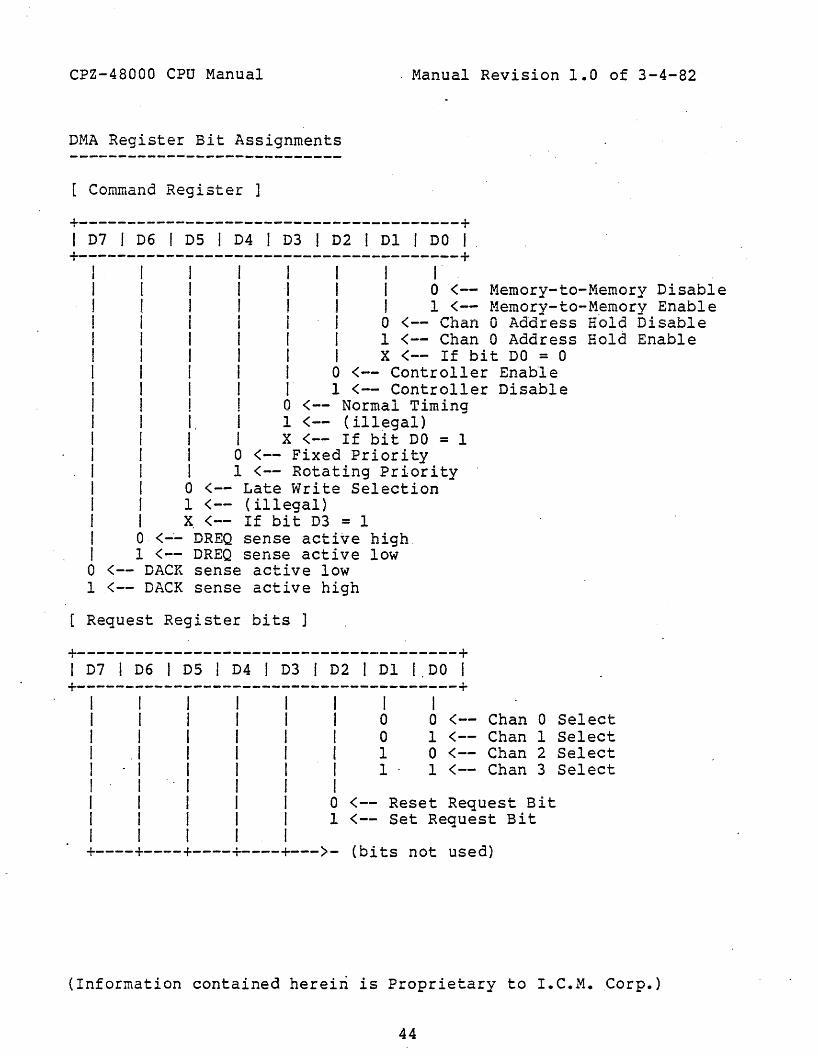
CPZ-48000 CPU Manual
DMA Register Bit Assignments
[ Command Register ]
. Manual Revision 1.0 of 3-4-82
+---------------------------------------+I D7 I D6 I D5 I D4 I D3 I D2 I Dl I DO I
+---------------------------------------+I I I I I I I I-I I I II I I 0<-- Memory-to-Memory DisableJ I I J f J I 1 <-- Memorv-to-Memorv EnableI I I I I I 0 (-- Chan 0 Addiess a61d 5isableI I I I I I 1 <-- Chan 0 Address Hold EnableI I I I I I X <-- If bit DO = 0I I I I I 0 <-- Controller EnableI I I I I 1 <-- Controller DisableI ! I ! 0 <-- Normal TimingI I I I 1 <-- (illegal)I I I I X <-- If bit DO = 1I I I 0 <-- Fixed PriorityI I I 1 <-- Rotating PriorityI I 0 <-- Late Write SelectionI I 1 <-- (illegal)I I x. <-- If bit D3 = 1I 0 <-~ DREQ sense active high.I 1 <-- DREQ sense active lowo <-- DACK sense active low1 <-- DACK sense active high
Request Register bits]
+---------------------------------------+I D7 I D6 I D5 I D4 I D3 I D2 I Dl 1.00 I+---------------------------------------+
I I I I I I I II I f I I I 0 0 <-- Chan 0 SelectI I I I I I 0 1 <-- Chan 1 SelectI .1 I I I I 1 0 <-- Chan 2 SelectI . I I I I I 1 1 <-- Chan 3 SelectI I I I I II I I I I 0 <-- Reset Request BitI I I I I 1 <-- Set Request BitI I I I I+----+----+----+----+---)- (bits not used)
(Information contained hereiri is Proprietary to I.C.M.Corp.)
44

CPZ-48000 CPU Manual
[ Mode Register Bit Assignm~nts
Manual Revision 1.0 of 3-4-82
+---------------------------------------+I D7 1 D6 I D5 I D4 I D3 I D2 1 Dl I DO; I
+---------------------------------------+I r I I - I I 1 II I j I 1 I a . 0 <-- Chan 0 Select1 I" I 1 1 1 0 1 <-- Chan 1 Sel ectI 1- I 1 1 I 1 0 <-- Chan 2 SelectI" I I I I 1 1 1 <-- Chan 3 SelectI "I 1 I 0 a <-- Verify Transfer (not used)I I I I 0 1 <-- Write TransferI I I I 1 0 <-- Read TransferI I I III <-- (illegal)I 1 1 I X X <-- If bits D6 & D7 = 111 I I 0 <-- Disable AutoinitializeI I I 1 <-- Enable Autoinitialize1 I 0 <--Select Address IncrementI I 1 <-- Select Address Decremento 0 <-- Demaha" Mode "Selecto 1 <-- Single Mode Select1 0 <-- Block Mode Select1 1 <-- Cascade Mode Select
Status Register Bit Assignments
+---------------------------------------+I D7 I D6 I D5 I D4 I D3 I D2 I Dl I DO 1
+---------------------------------------+1 I I I I I 1 II 1 I I I I I 1 = Chan 0 has reached T.C.I I I I I I I = Chan I has reached T.C.I I I I I I = Chan 2 has reached T.C.I I . I I 1 = Chan 3 has reached T.C.I· I I II I 1 II 1 1 1 = Chan 0 is Requesting1 I 1 = Chan 1 is RequestingI 1 = Chan 2 is Requesting1 = Chan 3 is Requesting
(Informatic, contained herein is Proprietary to I.C.M. Corp.)
45

CPZ-48000 CPU Manual Manual Revision 1.0 of 3-4-82
[ Mask Register (single mask bit) Assignments 1
+---------------------------------------+I D7 I D6 I D5 I D4 i D3 I D2 iDl I DO. I+---------------------------------------+
I I I I .. 1 I I II I I I I I 0 0 <-- Chan 0 Mask bit SelectI I· I I I I 0 1 <-- Chan 1 Mask bi t SelectI I I I I I 1 0 (-- Chan 2 Mask bit SelectI I I I I I 1 1 <-- Chan 3 Mask bit SelectI I I I I IIii '·1 i 0 (-- Clear Mask bitI I I I I 1 (-- Set Mask bitI I I I I+----+----+----+----+---> (bits not used)
Mask Register (all mask bits) Assignment]
+---------------------------------------+I D7 I D6 I D5 I D4 I D3 I D2 I Dl I DO I
+---------------------------------------+I I I I I I II I I I I I a <-- Clear Channel 0 Mask bi tI I I I I I 1 <-- Set Channel 0 Mask bit1 I I 1 I 0 <-- Clear Channel 1 Mask bitI I I I I 1 (-- Set Channell Mask bitI . I I I 0 ,(-- Clear Channel 2 Mask bitI I I I 1 {-- Set Channel 2 Mask bitI I I 0 (-- Clear Channel 3 Mask bitI I I 1 <-- Set Channel 3 Mask bi tI I I+----+----T---~+--> (bits not used)
Serial Port A and B Software Description
Both serial ports A and B must be initialized after a systemreset is performed before they will communicate with any terminals orthe like. Each channel has a set of registers which program the_device for a certain function. As we are only concerned withprogramming each channel for standard RS-232C interfacing, we will notdescribe the other functions that each channel contains here. Forfurther information about the SDLC/HDLC functions, refer to the ZILOGsupport chip manuals.
(Informatio~ contained herein is Proprietary to I.C.M. Corp.)
46

CPZ-48000 CPU Manual Manual Revision 1.0 of 3-4-82
Below is a software example for initializing the SIa ports A andB for standard RS-232C interfacing.
C!1NDACMNDB
EQU'EQU
8lH83H
;command port chan Aicommand port chan B
iiinit channel A:iget length of init table in reg b;get cow~and port into reg c.iINITA: LXI
LXIOTIR
B,(CHANAE-CHANA) SHL 8 OR CMNDAH,CHANA ipoint to chan A init table
;block i/o send it;iii1.it channel B:iget length of init table in reg b,iget command .port into reg c.i
. INITB: LXILXIOTIRRET
B,(CHANBE-CHANB) SIlL 80RCMNDBH,CHANB ipoint to chan B init table
iblock i/o send it
iiinit tables for channel A and B
. iCHANA: DB l8H,04H
DB 4CH,01HDB 00H,03HDB OElH,OSH
DB OEAHCHANAE EQU $;CHANE : DB l8H,04H
DB 4CH,01HDB 00H,03HDB OElH,OSHDB OEAH
CHANBE EQO $
ireset A, write reg 4;x16 clk, 1 stopbit,no parity, write reg 1ino interrupts, write reg 3irx 8 bits, autoenables, rx enable,;write reg 5itx 8 bits, tx enableiend. of table marker
;end of table marker
Channel A and B Baud Rate Software Example
After the SIO has been initialized, you should next set the BaudRate for each of the two ports to match the device to which it isattached. Below is an example of setting the timer channel for each ofthe serial ports. Timer channel 0 controls serial port A, and Timerchannel 1 controls serial port B. The crystal frequency used to
(Information contained herein is Proprietary to I.e.M. Corp.)
47

CPZ-48000 CPU Manual Manual Revision 1.0 of 3~4-82
control the timer is a 2.4576 MHz crystal. This value· lends itself toeven binary divisions as illustrated below and can be. used to programthe timer channel directly as the count~
.,;equates for timer channeliTCHO EQU OBOHTCHI EQU OBlHTCMND EQU OB3HCHAND to'f"ITl 36E• ~~\J
CHBMD EQU 76Hiibaud rate equatesiCLK EQU 24576B38400 EQU CLK/384/16B19200 EQU CLK/192/l6B9600 EQU CLK/96/16
. B4800 EQU CLK/48/l6B2400 EQU CLK/24/16B1200 EQU CLK/12/l6B600 EQU CLK/6/l6B300 EQU CLK/3/16.I
;set chan A baud rate subroutine
ichannel 0 timer;channel 1 timer;timer command port;chan 0 modeichan 1 mode
;crystal freq .(KHz);38,400 baud;19,200 baud;9600 baud;4800 baud;2400 baudi1200 baudj600 baudj300baud
iBAUDA: LXI
MVIMVIOUTOUTPOUTPRET
D,B9600C,TCHOA,CHAMDTCMNDED
iselect 9600 baud;reg c = timer chan 0 portiget command byte;send to timer command port;send low baud byte;sen4 high baud byte;return to caller
;;set chan B baud rate subroutine;BAUDB: LXI
MVIMVIOUTOUTPOUTPRET
D,B19200C,TCHIA, CHBMDTCMNDED
;select 19200 baudireg c = timer chan 1 port;get command byte;send to timer command port;send low baud byte;send high baud byte;return to caller
(Information contained herein is Proprietary to I.C.M. Corp.)
48

PFJ\'SOkALITY OOAAD _. ~23'VNO Il1DEfII
PART NlJ1BER - RPBloo
The f\:'S232/}{l I1JDEl'I PersOna i i ty Board provides i\'S232 drivers andreceivers, teNiinations and JUllper options to 1l1tel"face any simple RS232 aevice su(h as ~1 terllinalst serial printers or anyother serial dWlce not r-equirinq an e:t.tensive handshake protocol, _1 th the CPZ -4BJOO CPU.
CPU (Jl)
DESCRIPTION
12
DSR*we
DATA SET READY TO CPUH/C
3 we WC-4 T:ill TR~IT DATA FR~ CF~
" R"J.D RECEIVE DATA TO C~JJ
b RTS* REWEST TO SEND DATA FROI'I CPU7 CTSt CLEAR TO SEND TO CF1J8 DeDI DATA CARRIER DETECT TO CPU9 DTR* DATA TERnINAL READY FRa'l CPU
10 Rt«';t RINGING INDICATOR TO CPU11 WC HIe12 GND GROUND13 +lbVDC +16VDC14 -16VOC -16VOC15 +SVDC +5VDC1"6 we t~/C
-1-

PERIPHERAL LJ2)
PIN ;.¥J. SIGNAL ~E DESCRIPTION----------- ---------------------------------------..
4 SAFm GND SAfm cr.1Jt1ID.L
2 TXD TRANSJ"tIT DATA FROM PERIPHERAL3 RXD RECEIVE DATA FRO'! PERIPHER.AL4 we MlC5 CTSt C!.f.AR TO SEND TO PERIPHERAL6 DSR* DATA SET READY TO f'E.~IF'H£RAL7 . ~GND POWER ~'I)Jf;'D'"
8 DeDI DATA CAARIER DETECT TO PERIPHERAL9 we WC
10 WC HlC11 HIe wc12 we we13 we· NlC14 ·HlC Hie15 wc WC16 HlC WC17 ~jC WC18 MlC WC19 SRTS* SEmiDARY REOOEST TO SEND Th'Ol'f PERIPHERAL20 DTR* DATA TffitllNAL READY Ff\'OM PERIPHERAL21 we WC22 NlC we23 WC HlC24 N/C we~"c:; HlC we.....
CPU - ANSLEY 609-1617 ANSLEY 609-1630 <rCM SUPPLIED)
F'eri~eral - CAtflJN D~-731 CtiKH DB 255-731 (OJSTOt1ER £:Lf'FLIED)
,

SET l.F' It'lSTRUCTIlJ6
3 JUllip€r Areas are pro....ided: JA
JA
The CPU lay be required to provide hand.shaKi~ with the peripheral. tnrough the "SIgnal .. DCD" t If that handshaKing signal is required,
connect pin 2 to pin 3 lith tne Jumper provided. If no handshaKinqsIgnal is requil~ J connect pin 2 to pin 1.
JA J13 1LiZ3 0
AJJC,
The···CPU··liayrefjUlred to .provide-handSh.aKing withtheperiphera.L.. thtougtlme sign<!.li "eTS". Furthernore, it may accept the sIgnals "DTR" or"SRrs" through the input "CTS". The following options are avaUable:
Cont i <;Ul"at ion
la.;2a no hal'pj,sllaKinq provided to pel"lpheral at "CTS"la-3a penpheral' S "eTS" activated by CPU's "DTR"3a -3b Hot Usw3b- 3c no ~landshaKl nq provided to CPU's "CTS" by periphera I.s
'DTR" or "SRTS"2c-3c perlpt,eral's "DTR" or "SRTS" activates CPU's "CTS"lc -2c peri pnera I' s "DTR" or "Sr.nrs" aC!lvates CPU's "DSR"
-3-

JC
The perIpheral lay provide either of t]~ handshaking Sigl/als"sm" or "DTR". !Ius Jumper may select either siqnal as thesource to the Cf'U's "crs" or nDSR" inputs.
EXAff'LES
U Conii~iI'''e JA, \orB and \oIC as follows for a single terminalinterface:
JA : 1-2JB : la-2 t\J 3b-3c /2 c.- iC"
.D:C-::2-3
2> Configure JA, ~~ ana JC as follows for an A~acte~ SerIalF'nnter'! lDOOe I ~'-9501
.JA : 2.-3
JB : zc..-1"i2c.-1.c. i iC.-'2.c...
JC : j-2.
-),-

F~'T ~ER - FPBl00-Y:t
The FUf'Pt DIS:K mrrROllER persona Iity board provides linedrivers and receivers, terDinators, )~ic and a Jumper' optionto interface either an 8-inch or a 5 1/4-:ncn floppy disK drivelIIittt the CPZ-48OOC C?U. ADB25 connector is available as theiJl€ans to lnterfa:e ..im the ac:ive interface; hCXlJevel"t if thecable requlres other typeS of coemonly used connectors, adapters are avallable to tailor the interface appropriately.
INTERFACE RIDJIRfJ1Eh'TS
PIN t4).
123·456789
1011121314151617181920212223242S2627
SIGNAL NAf'E
GNDD51*GND
052*GHD053*GNDDS4.GNDDlf\'CGr;D
STEPGND~ITE DATA
-CNDWGATE·GNDTRACK 0*GNDItJR ITE PROT*GNDREAD DATA*GNDSSOGNDHiDGND
DESCRIPTION
GRCtINDDRIVE SELECT #1 FROM CPUGh'WIDDRIVE SELECT #2 ff\'OM CPUGRCUIDDRIVE SELECT #3 f1\'01'1 CPU~D
DRIVE SELECT #4 FROM CPU _GRruNDDIRECTION CONTf\'OL ffill'l CPUGRCUNDSTEP CONTROL n'OM CPUGROJt.IDWRITE DATA FROM CPUGROJND~ITE GATE FROI'I CPU~D
TRACK 0 STATUS TO CPUGROUNDWRITE PROTECT TO CPU~D
READ DATA TO CPUGh1lk4DSIDE SELECT OUTPUT FROM CPUGRCUNDHEAD LOAD COMMAND FROM CPUGRCUND
-1-

28?i30313233343S363738~
40
INDEX*GNDREADYGNDI'IDTOR ONGNDTX43GND+lbVDCGNDweGND+5VDC
INDEX PULSE TO CPUGRtlJNDREADY STATUS TO CPUGRCWDMOTOR 00 STATUS FROt"! CPUGRtJ.JNDr'r\ACK 43 STATUS t'r<Oi'i CPUGR(U.lD
+16VOCGRCtlNDHie(rl\'O..JND+SVDC
DB25 DRIVE INTERFACE (1.12)
PIN r1O. SIGNAl. ~E DESCRIPTION----------- -----------------------------------------
1 DSll DRIVE SELECT =1 to DRIVE interface2 DS2* DRIVE SELECT ~2 to DRIVE interface3 DS3* DRIVE SELECT =3 to DRIVE lnterface.; DS4* DRIVE SELECT #4 to DRIVE interface5 DIRel DIRECTlON CONTROL to DRIVE inter'face6- STEP* STEP CON~~L to DRIVE interface7 Lf<ITE )ATA* W~ITE DATA to DRIVE interface8 WRITE GATE* !.RITE GHTE to DRIVE interface9 TRACK 0 * TRACK 0 STATUS from DRIVE interface
101112131415161718192021222324")t)
irl<ITE Fh'OT*REAl} OilTAJ:SSO*HEAD LOAD*n-IDEX*READYnJTOR ~TX43*GM>GNDGNDGNDGfJ.DGNDGNDGND
IE:ITE PROTEC'l' STATUS froD! DRIVE in-rerfaceREAD DATA to DRIVE inerfaceSIDE SElECT OUTPUT to DRIVE interfaceHEAD LOAD COMMAND to DRIVE interfaceINDEX F1JLSES t"i"OI DRIVE interfaceREADY STATUS frOB DRIVE interfaceMOTOR ON CQr.MAND to DRIVE interfaceTRACK 43 STATUS to DRIVE lnterface~'OUHD
GRCliHD~:OUND
(rl\'OJNDGf\'OUNDGRCUNDGROJNDGROUND -2-

a-INCH ADAf1ER DR~y~ INTERFACE (J-51Ni
12
SIGNAL NAME DESCF:IF'TION
Gf\OOHDTRACX 43 STATUS to DRIVE interface
3 GND GF-'OtJND4 WC WC5 CND ~OOtID
6 WC HlC7 GND GND8 WC HlC9 bND (rl\'OtJND
10 we WC11 GND GJ\'OUND12 WC WC13 GND G~'OJND
14 sse SIDE SELECT OUTf~ to DRIVE interface15 GND GJ\OOHD16 WC N/C17 CND Gf\'OJND
·18 HEAD·~ HEAD LOAD ~D to DRIVE inte't"face19 GND Gf\'OUHD20 INDEX* INDEX PULSES fl~ DRIVE interface21 GND GROOND22 READY* READY STATUS fro. DRIVE interface23 GND G1\OOND24 roTffi ON* nQTOR OM COMMAND to DRIVE interface2S GND Gi\'ClIHD26 OSl' DRIVE SELECT =1 to DRIVE interface27 GND Gf\'OUHD28 DS2f DRIVE SELECT =2 to DRIVE interface?t GN.D Gr.OOHD30 DS3* DRIVE SELECT =3 to DRIVE interface31 GHD CI\'C.lIJHD32 DS4f DRIVE SELECT =4 to DRIVE interface33 GND GI\'OUHD34 DIRe* DIRECTION CONTROL to DRIVE interface3S GND Ct\'OUHD36 STEP* STEP COMMAND to DRIVE interface37 GND GROOHD38 ~In: DATAl ~ITE DATA to DRIVE intel"face39 GND GF-OOND40 WRITE CATE* ~ITE GATE to DRIVE inter'face41 GHD Gf\'OUHD42 TRACX 0 * TRACX ZERO STATUS fr~ DRIVE interface43 GND Gf\'CUND44 URI1E F'kt1T. WRltE Ph~ECT ~~A1US from DRIVE irterf~ce
JS eND Gf\OOHD~ READ DATAl REAli DATA to DRIVE interface47 CND GROUND4e I"!/C tV(:4~ 00 G~'CllHD
5-J NIl: WC
-3-

5 ./4-JMCH ADA?TIS~ DRIVE INiERF~CE (J-5 1/4IN)
PIN t-lJ.
123456789
101112131415161718"lY202122232425262J287t30
·31323334
SIGNAL H~
GNDWCGNDWCGND054*GND
GND051*GND052*GND053*GNDnJm;: ~GNDDIRe!GNDSTEP*GNDItJRITE DATA*GND~'RITE GATE*GNDTRACK 0 *GNDWRITE ~'OT*
GNDREAD DATAfGNDSSO*GNDN/C
DESCRIPTION
Gf\ilINDWC~'OUND
WCfrl\'OUNDDRIVE SELECT =4 to DRIVE interfaceGROUNDINDEX* F~LSE STATUS fro~ DRIVE interfaceG1\'OUNDDRIVE SELECT =1 to DRIVE interfaceGROUNDDRIVE SELECT =2 to DRIVE interfaceGROUNDDRIVE SELECT =3 to DRIVE interfaceGf\'OUNDnoTOR ~i COMMAND to DRIVE interfaceGROUNDDIRECTION C(}.lTROL to DRIVE lnter'faceGF-.'OUNDSTEf·'~ND to DRIVE interfaceGl\'OJNDWRITE DATA to DRIVE interfaceGI\'OJND~ITE GATE to DRIVE intel'faceGI\'OUNDTRACl ZERO STATUS fl'Om DRIVE interface~OOHD
iJRlTE Ph'OTECT STATUS from DRIVE interfaceGROUNDREAD DATA to DRIVE interfaceGROJNDSIDE SElECT OUTPUT to DRIVE interfaceG.'OUNDWC
-4-

MTI~ ~CTOR REQUlRE~S
~ the fallowing table to deteralne the type of matin<] connector'to use:
-------~~~----~~._---~----------- '-~~';~'~-~~~~
CWIGURATICH
8- INCH/HEADER PLLG ADAf1'ffia-INCH/EIX;E CONNECTffi ADAPTER5 1/4- INCH/HEADER PLLC ADt:i'TER
PART t'iU/'IBER
FPB100·UFF'B1OO-12FPB1OO-21
CONNECTOR n'F'E
ANSLEY 609-5030AMP 840-225F-ASO-lANSLEY 609-3430
5 Ii4- INCH/EDGE DJ~TOR ADAPTER FF'BI 00-228-INCH OR 5 1/~-IHCH W/O ~DAPTER FPBIOO-OO
AMP 840-225F-A34-1CAANON DF25S-731
rmE: MTI~ COHNECTffiS ME DJSTOMER SUPPLIED and theconnector re~ired 1S a function of the cabl etype the custoler wishes to insta'j \. Connector'~qu1valents &ay be used.
;ET Lf' INSThtCTIONS
JUJlper F',JA IS provld.t?d to configure the base personal ity .ooar'dtor elthei' a-inch or 5 1.t4-inch oper'ation. The JlJllpel" selectsthe "READY" slgna I ff'C* the B-IOCh drive interface or a signal~nerated on the oaSlS of index pulse occur'ranees fal' the 5 1/4loch drl\'e operanon. Insta II a Jllalper frm pin 2 to 3 for 8lnch operation. Ins'ta 11 a JUlper fl~ pin 1 to 2 for 5 1/4loch operat1on.
60001I ;::. '3,
-5-

PEi\'SONALIT'f BOARD - l\'S232Jf1JLL l'WJDE!'l
F'AA'T riJiBER - rfB100
The RS232CIFULL /{JDE11 PEfSCtW.ITY BOAAD provldes FSm drivers/receivers and JWlper options to interface asynchr'onous or synchronus lOdess lith varyinq typ.:-s of bit oriented. protoco l5 suchas 1m B. SyOCJ HDt.C or SDLC. JWipers provided enable the user'to confiqure the boc:rd fop either 'isyncr1ronous or synchronousoperation. If synchrcnous ope--atlon is sel ected, Jumper's ar'eprovided to seiect either a baud rate ciocK or a transait clocKlOdei. In syncnronous lICX1efts, the r'eceive clocK is allaYS provlded ':1; the mea;
INTERFACE RIDUIFJ:.l'lENTS
CPU (Jl)
PIN NO. 51GNAL Nfi't£ DESCRIPTION'-------.--- ----- --- --- ------- --- -- _.- ------- --
1 DSR* DATA SET READY TO Cf'U2 we WC3 we tue4 TXD TRANSt-lIT DATA Fh'OM CPU5 RXD RECEIVE DATA TO CPU6 RTS* REOOEST-TO -SEND FROM CPU7 CTS* CLEAR- TO-SEND TO eFtJ8 DCDt- DATA CARRIER DETECT TO CPU9 DTR* DATA TER~INAL READY ff\'OM CPU
10 RNG* Rn.cING INDlCATffi TO CPU11 NIC we12 GND GRCl.J.lD13' +16VOC +16VDC14 -16VDC -16VDC15 +5VDC +5VDC16 we NlC
-1-

F'ERIF'HERAL (\,T2)
PIN t{). SIGNAL~ DESCRIF'TIDN----------- ----------------------------------
1 SAFETYGND SAFETY G~D2 TXD TRPlQIlT DATA TO PERIPHERAL3 RXD* RECEIVE DATA FROM PERIF~L
4 f\'TS REOOEST-TO-SF.HD TO PERIPHERAL5 CTS CLEAR-ro-SFJill FROM PERIPHERAL6 DSR DATA sn READY Ff\'OM PERIPHERAL7 POWER GND F'OJER GROl.JND8 DeD DATA CARRIER .DETECT Ff\'OM PERIPHERAL9 Hie- N/C
10 WC WC11 WC WC12 WC WC13 WC WC14 we we15 ncLx ~SMIT CLOCK TO PE.E<IF'HEAAL16 HlC we17 RXGU RECEIVE. CLOCK·FROM. gERIF'HERAL18 HIe we19 we HlC20 DTR DATA TEfJllHAL READY TO PERIPHERAL21 we we22 RNG RINGIHG IHDlCATOf:: FRO!'! PERIPHERAL23 WC HlC24 MuD :U BAUD CLOeX TO PERIPHERAL25 N/C WC
-2-

"\ATl~ CCNiECr~ REGUIREnENTS
CUSTorlEli TO SUP?LY
CANHON DR25S-731 or equivalent.
SET Lf' INSTF.1JCTIONS
The board aay be cenfigLred for either asynchl"Ol1OUs or synchronouslilOdem requiretlents.
a) Asynchronous ModeelS
F\.IB, PJC, P1JD, and P.JE are all open.
b) SyochrOoous /bjefls
---------------~--
1) Q='Z -4aOOO SUPPLIES TRANS~IT CLOCX
Note: Cut P.JB 1-2 and 2-3 on CPZ -48000 ifusing Port Aof SID.
Cut PJA on CF'Z-4BOOO if uSlng Port Bof SID.
2) CPZ-4BOOO s..f'PLIES BAUD RATE CLOCK
Same as (1) above e'f.cept P"JB is connected instead of PJC.
C) If sa f c~J ground of the modetl is to be ned Ie loqicground. connect PJA.
..,-