0 ,qme flu ld osci-t-lato rs · ,qme flu ld osci-t-lato rs a.pril 196 9 ... sidering that air from...
TRANSCRIPT
~: ~ .._. o:.: Qa ... 0
TR-1438
,QME FLU lD OSCI-t-LATO RS
A.pril 196 9 - ""
-;:,. ~ ..
. '.
'. L
U$: . AfH,f"i .. MAl~ •.. Rw·t. COMM~N D
RRY . Df.~r~6Nc; .7.LABO:RJ\TC.)F~1ES
• ~· ., ' i ' ' '. ' .• "
,. ·;~~:-:.. f..<i>::d>~~~"-\/\;~, .. ,. ~t~.s-' fd.·:'fl: JJi·,'} ·~·"l'<lt~·· h:~ ,1'-'~f.t;t 1-!t.:~J} ·"~ .~ ·~r~'l ,' '.;,_._, . .:,.,".. , U ...,_ ('~ "- §.. • '~ 'lt'~-,' .W'I ; 1...._. 'd I [ t {J ~

DA-1T061102A33B AMCMS Code: 5011.11.71200 HDL ProJ: 41100
AD
TR-1438
REVIEW OF SOME FLUID OSCILLATORS
by
Carl J. Campagnuolo
Henry C. Lee
April 1969
H • n • i
US ARMY MA7ERILL COMMAND
HARRY DIAMOND LABORATORIES WASHINGTON DC 20433
1MIS UXUMINI M»S BUN IVPMMU K)H MiblH, •• I ; • : «ND SALL lib D'SlkbliUiN IS UNLiM ID

·•·
THIS DOCUMENT IS BEST QUALITY AVAILABLE. THE COPY
FURNISHED TO DTIC CONTAINED
A SIGNIFICANT NUMBER OF
PAGES WHICH DO NOT
REPRODUCE LEGIBLYo

ABSTRACT
f Fluid oscillators of various types have been
developed and applied to fluidic systems for sens- ing or missile control. The operating characteristics of these oscillators, including the dependence of the frequency on the stagnation pressure and temperature, are a function of the type of return loop employed for maintaining oscillations.
This report discusses and summarizes the operat- ing principles, design, frequency variation and ap- plications of some of the most prominent oscillators such as: The sonic, lumped R-C-R and L-R, edgetone, ringtone, and vortex oscillators.
CONTENTS Page
AnSTHACT 3
1. INTHOniCT ION 7
? . EDGKTONE AND R INGTONK OSC lUATQM 7 2.1 Kdm'tont- or VVcdpctonc Oscillator with a ResonatinR
Cav 11 y 7 '1.2 Hinntone Oscillator 11
3. SON K" OSC ILtATQM 11 3.1 Sonic Oscillator with Interconnect Ing Channel 11 3.2 Sonic Oscillator with Internal Feedback 1 «cop or
Temperature Sensor 18
J. R-L OSC ILLATOR 20 I . 1 Temperature Insensi t i vity 20
■1.2 Pressure-Controlled Oscillator 23
B . RELAXAT ION OSC ILLATOK , 28
G. VORTEX OSC ILIJVTOR 31
7. POSTSCRIPT 37
«. I.ITERATl'RE CITED 4.T
BYMMU 41-42
0i3TRIBlT!ON 43-54
ILLUSTRATIONS
FiKiire
1. .Ict-wedRc-resonat or oscillator..,,. 8
2. WedRe-tone oscillator operational characteristics 10
3. Fluid particle path length 10
4. Wedgetone oscillator frequency cliaracterist les 12
5. Rinj;tone oscillator-pressure versus frequency 13
6. Schematic of sonic oscillator with interconnection channel 14
7. Sonic oscillator (with interconnectIUR channel) frequency versus power-.jet supply pressure IG

ILLUSTRATIONS (Cont'd)
Figure Page
8. Sonic oscillator frequency versus interconnection channel length 17
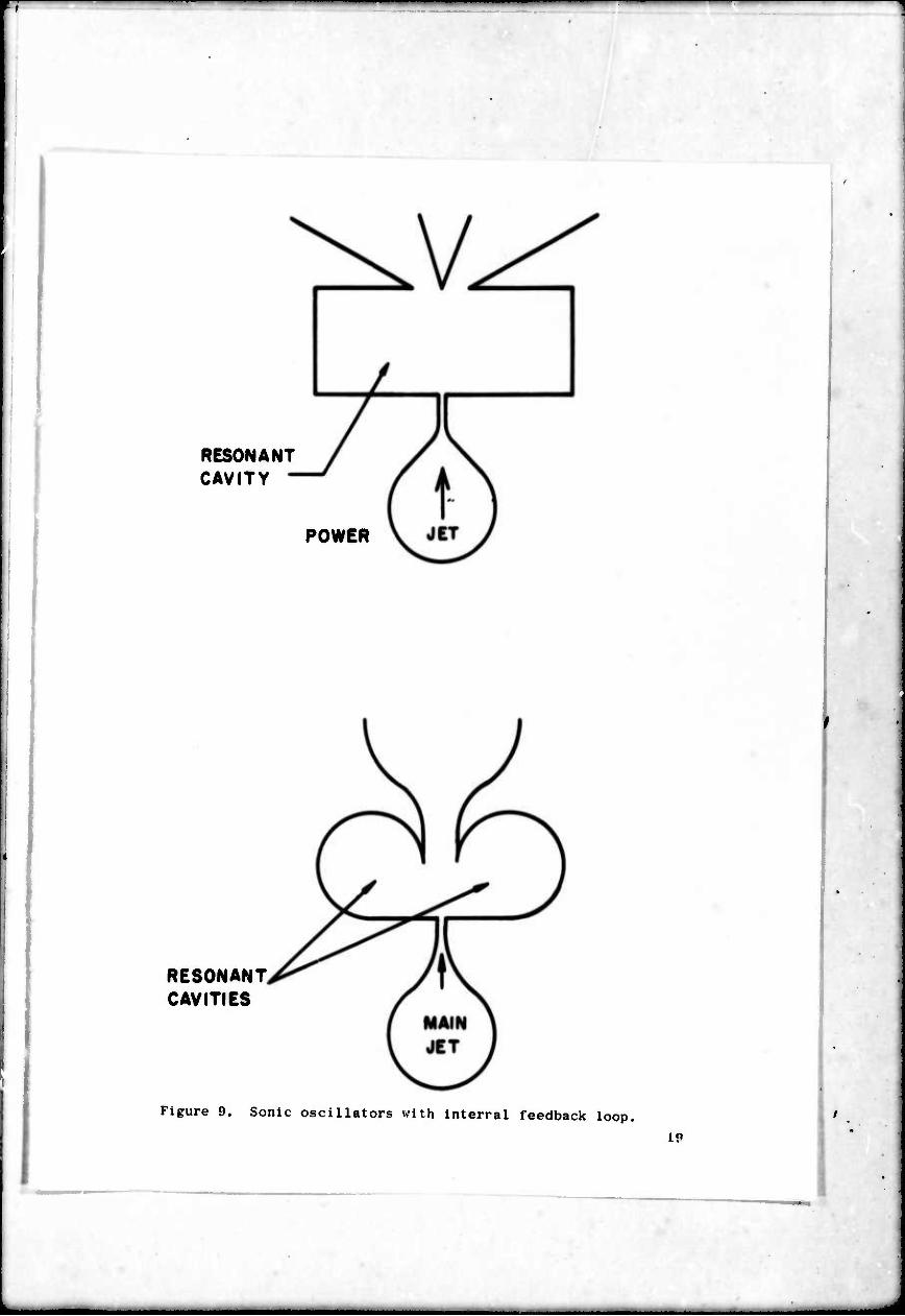
9. Sonic oscillators with internal feedback loop 19
10. Resistance-Inductance (R-L) feedback oscillator 21
11. R-L oscillator computed frequency versus temperature ?4
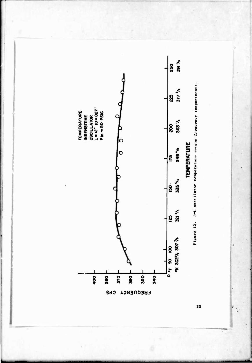
12. R-L oscillator temperature versus frequency (experiment).. .25
13. R-L pressure controlled oscillator. Comparison of axperi- tnont and theory 91
14. Oscillator frequency versus Stagnation temperature 2{)
15. Relaxat Ion osc i llator and digital amplifier 30
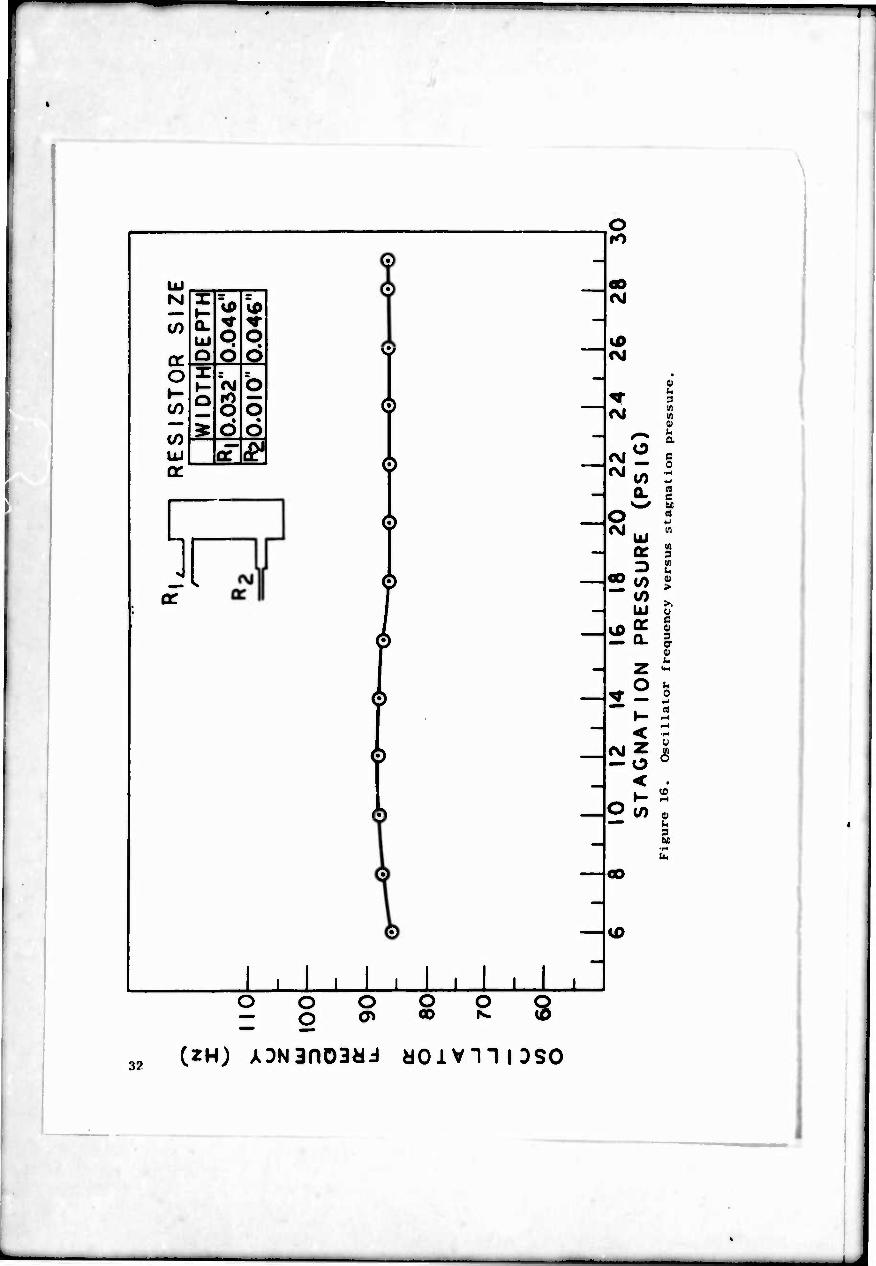
16. Oscillator frequency versus stagnation pressure 32
17. Oscillator frequency versus stagnation temperature 33
18. Relaxat Ion oscillator 34
19. R-C-R osc I llator as time base for a t Imer 35
20. Four-stage fluid amplifier assembly for missile control system 36
21a. Vortex oscillator schematic 38
21b. Vortex oscillator flow model 38
22. Pressure In upstream vortex chamber versus frequecny (Hz) . .39
1. INTRODUCTION
Mechanical oscillators, such as the pendulum or balance wheel for clocks and windmills, have been extens ively used in the past. Electronic oscillatora of many kinds have contributed greatly to the advance of modern electronic conununicat ion. Recently, the inven- tion of fluid amplification has generated interest in fluid oscil- lators and their application to sensing, timers, and 1luidic control systems. All those oscillators utilize a direct-current energy source which they convert, with some losses, to an alternating output. In the case of the balance wheel in mechanical clocks, the energy is stored in a spring; for the electronic oscillator the energy is provided by a battery or a d-c power supply; for the f luicT'osci I lator the energy is derived from compressed air. which is directed through an orifice or a power nozzle.
An oscillator can be regarded as an amplifier in which some of the output is returned by a feedback loop to the input in such a phase as to cause periodic alternations. In the pneumatic oscilla- tor, the geometrical configuration of the feedback also determines the chief properties of the oscillator, e.g., its frequency and the dependence of the frequency upon stagnation conditions. Hence, oscillators are named according to the type of feedback loop used. A sonic oscillator is one in which the speed of propagation in the feedback loop is approximately equal to the speed of sound; an R-L oscillator uses a fluid resistance and a fluid inductance; an R-C-R uses a fluid resistance-capacitance-resistance. An edgetone oscil- lator is triggered into oscillations by a series of vortices, gene- rated at the amplifier splitter, which feed back to the nozzle. A vortex oscillator employs the characteristics of vortex flow. The various kinds of oscillators respond differently to their input stagnation conditions. The frequency of a pneumatic oscillator gen- erally is a function of these since the speed of sound in a gas depends on its temperature. The sonic oscillator's dependence on temperature can be used advantageously in a temperature sensor *here thermocouples or similar devices are inapplicable. For pneumatic timers that re- quire a time base whose frequency is independent of temperature and pressure, an R-C-R oscillator can be designed. An R-L oscillator can be designed as a pressure sensor since its frequency is pressure sensitive but temperature insensitive. The wedgetone and ringtone oscillators are capable of K^neratlng high intensity waves, which find wide applications in industrial processes.
2. EDCLTOXE AND RINGTONE OSCILLATORS
?. 1 Edgetone or Wedgetone Oscillator with a Resonating Cavity
One of the pneumatic oscillators of considerable interest in fluldics is the edgetone-resonator type. Figure 1 shows a Jet-edge

Open Resonator
Figure 1. .Itt-wedRO-rosonator oscillator.
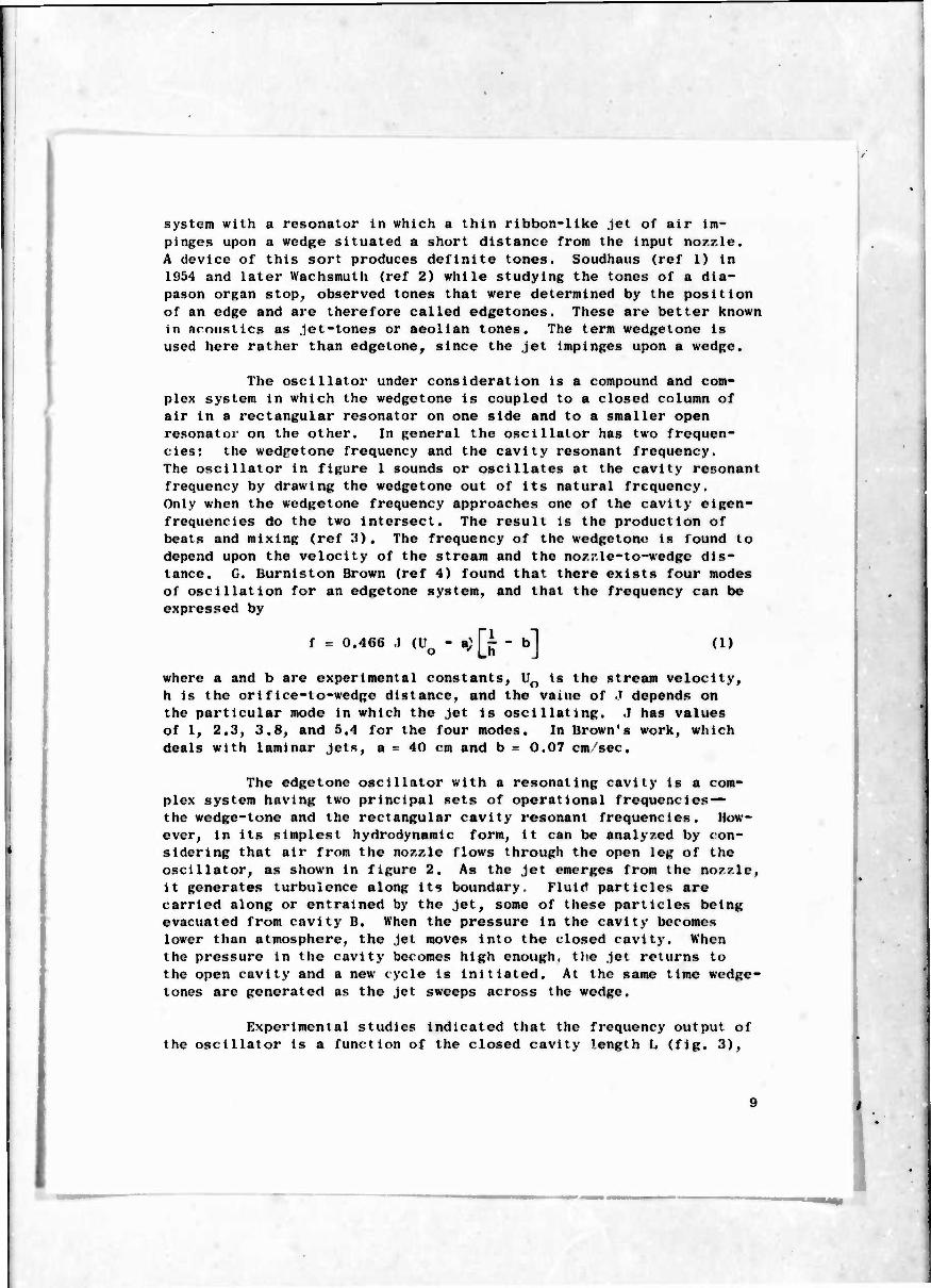
system with a resonator in which a thin ribbon-like Jet of air im- pinges upon a wedge situated a short distance from the input nozzle. A device of this sort produces definite tones. Soudhaus (ref 1) in 1954 and later Wachsmuth (ref 2) while studying the tones of a dia- pason organ stop, observed tones that were determined by the position of an edge and are therefore called edgetones. These are better known in nmustics as Jet-tones or aeolian tones. The term wedgetone is used here rather than edgetone, since the Jet impinges upon a wedge.
The oscillator under consideration is a compound and com- plex system in which the wedgetone is coupled to a closed column of air in a rectangular resonator on one side and to a smaller open resonator on the other. In general the oscillator has two frequen- cies: the wedpetone frequency and the cavity resonant frequency. The oscillator in figure 1 sounds or oscillates at the cavity resonant frequency by drawing the wedgetone out of its natural frequency. Only when the wedgetone frequency approaches one of the cavity eigen- frequencies do the two intersect. The result is the production of beats and mixing (ref 3). The frequency of the wedgetone is found to depend upon the velocity of the stream and the nozzle-to-wedge dis- tance. G. Burniston Brown (ref 4) found that there exists four modes of oscillation for an edgetone system, and that the frequency can be expressed by
f = 0.466 .1 (Uo - a;[i - b] (1)
where a and b are experimental constants, U0 is the stream velocity, h is the orifice-to-wedge distance, and the value of .T depends on the particular mode in which the Jet is oscillating. .1 has values of 1, 2.3, 3.8, and 5.4 for the four modes. In Brown's work, which deals with laminar Jets, a = 40 cm and b = 0.07 cm sec.
The edgetone oscillator with a resonating cavity is a com- plex system having two principal sets of operational frequencies— the wedge-tone and the rectangular cavity resonant frequencies. How- ever, in its simplest hydrodynamic form, it can be analyzed by con- sidering that air from the nozzle flows through the open leg of the oscillator, as shown in figure 2. As the jet emerges from the nozzle, it generates turbulence along its boundary. Fluid particles are carried along or entrained by the Jet, some of these particles being evacuated from cavity B. When the pressure in the cavity becomes lower than atmosphere, the Jet moves into the closed cavity. When the pressure in the cavity becomes high enough, the Jet returns to the open cavity and a new cycle is initiated. At the same time wedge- tones arc generated as the Jet sweeps across the wedge.
Experimental studies indicated that the frequency output of the oscillator is a function of the closed cavity length L (fig, 3),

■CAvtrr j
>VgZZ Z. £
Figure 2. Wodee-tonc oscillator operational characteristics.
FiRure 3. Fluid particle path Icngth,
I
10

the capacitance of the cavity chambers, and the input pressure. Figure 4 shows the variation of frequency with input pressure with the greater variation of frequency In tl ■ lower pressure range.
2.2 Ringtone Oscillator
The ringtone oscillator Is an axially symmetric structure with a cross section like that of a wedgetone oscillator. As shown in figure 5, it consists of an annular nozzle and a resonating cavity. The annular pattern is attained by placing a cylindrical centerbody In the nozzle. When air is introduced through the nozzle orifice, flow separation occurs over the centerbody surface. This induces the Jet outer streamlines to converge at a circle beyond the center- body; the result is a reduction of the effective annular Jet diameter. The gas then impinges on the edge of the resonator cavity, producing a ringtone. The ringtone is the dominant frequency of the oscillator whenever the orifice is very close to the entrance of the resonator. The oscillator when used In this particular configuration serves to generate high-intensity oscillations in the sonic or ultrasonic re- gime (ref 5). When the orifice Is set back from the resonant cavity, the frequency output is a function of the length and the volume of the cavity. As phown in figure 5, the frequency is pressure in- sensitive for this case. The ringtone oscillator can be used to generate high-intensity waves In the frequency range between 1 and 10 kHz. LitsiP1? (ref 5) has shown that when this oscillator is used with a reflector, its efficiency (acoustic power input/pnemuatic input) Is almost doubled. This oscillator or acoustic generator is used in industrial processes. For example, in the paper mill In- dustry, it is used to deflate the foam recovered from the pulp washers, High-intensity sound generators (ref 6) can also be used in liquid or vapor degreasing and cleaning processes. Finally, a large ring- tone oscillator, better known as an acoustic generator, operating in the frequency range between 2 and 4 kHz, at Intensity greater than 150 dB, could be used to disperse a crowd during a riot.
3. SONIC OSCILLATORS
3.1 Sonic Oscillator with Interconnecting Channel
The sonic oscillator (ref 7) consists of a high-gain digital amplifier in which a feedback path is achieved by interconnecting the control ports (fig. 6). If the output has Just shifted to the right outlet, entrainment reduces the pressure in the right control nozzle. An expansion wave propagates through the interconnection channel toward the left control nozzle. Simultaneously, atmospheric air coming through the left outlet starts a compression wave at the left control nozzle, which propagates through the same channel toward the right control nozzle. Both waves reach their destinations simultane- ously and deflect the output to the left outlet. This starts a chain
11
1

r
(&€*Oj A 3H3n OJ&J
12

— ">
b
I
!
Si
b
N < N z O z o
LÜ M Q: < -I, D '^,*,' Z Z
• <
i Q BSSSSSB&BSSSa
S^S—/
I« 3
Oi Ifl ^-x IH
o 1 ■B
U) 0
a. 3 >-* m
0)
^ UJ E a a: h 3 0 *-< to (d
—i
V) ■*4
UJ o a (A
0 m a. 0) c 0
1 »o
I
I 1 O
? 1
o o O
O O O
O O O
(2H) ADN3nD3di
!3

L£FT OUTLET
LIFTCONTROL AfOZZLE
R/SHT OUTLET
3PL/TTEP
R/6HTC0NTROL OZZLE
/
-POWER J£T HOZZLZ
POWER J£ T CHA MBER
± INTLRCONNECTfON CHANNEL
Figure 6. Schematic of sonic oscillator with interconnection channel.
\'\
.

of events which Is similar but of opposite polarity, and a short time later the output is deflected to the right, completing one cycle and initiating the next. The period of oscillation is an inverse func- tion of the speed of wave propagation of the fluid in the feedback loop. For small differential pressure across the jet and for an interconnection line whose cross section is not too small, the speed of wave propagation is nearly equal to the free speed of sound. Then the period of oscillations is
T = 2L ■a
(2)
where L = length of the interconnecting feedback path and a« = free speed of sound. From equation (2) it follows that the frequency is
(VR T)1 e
2L (3)
where y is the specific heat constant, Rg is the gas constant, and T is the absolute temperature.
From equation (3) it is evident that the frequency is temperature dependent. The supply pressure and ambient pressure also affect the frequency. Figure 7 shows the dependence of the frequency on stagnation pressure for two lengths (2 and 4 ft) of interconnect- ing channel.
Figure 8 indicates the variation of frequency when the length L of the interconnecting channel is varied. Comparison between the experimental values and those obtained from equation (3) seems to show good agreement. The frequency in equation (3) is derived on the assumption that the switching time of the amplifier is negligible compared with the wave travel time In the interconnecting channel. Experiments (ref 7) indicate that the switching time ts can be ex- pressed as
s 2 \F fj (4)
where F is the measured frequency and f is given by equation (3). The switching time appears to depend on the length and diameter of the interconnecting channel. For longer lengths and small diameters the switching time increases. The dependence of the switching time on the geometry of the interconnecting channel is caused by the at- tenuation of the waves (traveling in the channel), thus increasing the rise time of the pressure difference at the control ports neces- sary to deflect the .ict . The sonic oscillator is a readily available, very versatile, and useful device. For laboratory use, one simply interconnects the control ports of a high-gain digital amplifier by a suitable lengt i of tubing. However, its applications are thus far
15

-I—*
6 /O 14 IB 22 £6 30 34 56 42 ROW£R JET P&£33UB£: fa) P3tG
Figure 7. Sonic oscillator (with interconnecting channel) frequency versus power-jet supply pressure.
16

Figure 8. Sonic oscillator frequency channel length.
versus interconnection
17
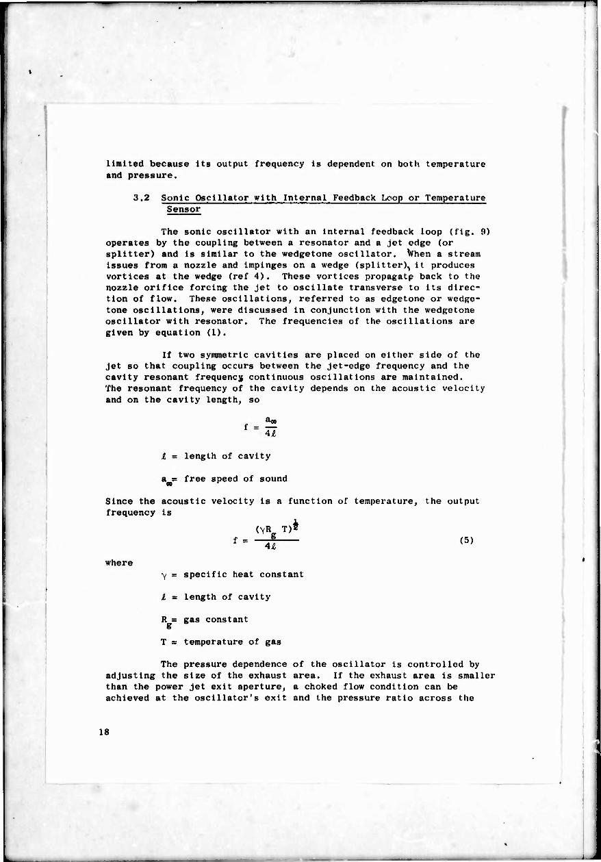
limited because its output frequency is dependent on both temperature and pressure.
3.2 Sonic Oscillator with Internal Feedback Lcop or Temperature Sensor
The sonic oscillator with an internal feedback loop (fig. 9) operates by the coupling between a resonator and a jet edge (or splitter) and is similar to the wedgetone oscillator. When a stream issues from a nozzle and impinges on a wedge (splitter)^ it produces vortices at the wedge (ref 4). These vortices propagatp back to the nozzle orifice forcing the jet to oscillate transverse to its direc- tion of flow. These oscillations, referred to as edgetone or wedge- tone oscillations, were discussed in conjunction with the wedgetone oscillator with resonator. The frequencies of the oscillations are given by equation (1).
If two symmetric cavities are placed on either side of the jet so that coupling occurs between the jet-edge frequency and the cavity resonant frequency continuous oscillations are maintained. The resonant frequency of the cavity depends on the acoustic velocity and on the cavity length, so
f =S i = length of cavity
a = free speed of sound 00
Since the acoustic velocity is a function of temperature, the output frequency is
f = (VR^T
4£
)* (5)
where y = specific heat constant
i = length of cavity
R = gas constant g
T = temperature of gas
The pressure dependence of the oscillator is controlled by adjusting the size of the exhaust area. If the exhaust area Is smaller than the power jet exit aperture, a choked flow condition can be achieved at the oscillator's exit and the pressure ratio across the
18
RESONANT CAVITY
POWER
RESONANT CAVITIES
Figure 9. Sonic oscillators with internal feedback loop.
If»

power noz/.le is smaller than the critical pressure ratio. Equation (5) shows that frequency is a function of temperature and this characteristic allows the clement to be used as a temperature sensor, Basically the main difference between the wedgetone oscillator with a resonant cavity and the temperature sensor is that, in the first case, the frequency of the wedgetone is higher than the cavity res- onant frequency, and, in the second case, the two are the same.
-n
The sensitivity of the temperature sensor, defined as the change in frequency per degree change in temperature, is
;T
f-r ( T-T T-T [(-H* -0 (6)
From equation (6) it appears that, if the frequency f taken at T Q O
is chosen very high, the oscillator will be more sensitive to temper- ature change. Obviously to operate at the high frequency the cavity must be small.
The basic advantage (ref 8) of this gas-temperature sensor is that it combines rugged construction with a response speed fast enough to measure temperature in a wide variety of applications ranging from blast furnaces to nuclear reactors. Recently the temper- ature sensor was installed in the leading edge of the vertical sta- bilizer of the X-15 experimental rocket plane to measure the jet stream temperature, which reaches values as high as 2800oF. This temperature sensor has also been used in gas turbines for automatic over-temperature control, automatic control of engine acceleration to avoid surging, and temperature indication in the cockpit (ref 8).
4. R-L OSCILLATOR
4,1 Temperature Insensitivity
Certain applications require the use of a pneumatic oscil- lator whose frequency is independent of cnanges in stagnation temper- ature but dependent on the pressure of the working gas. Such an oscillator could be designed using an inductance-resistance feedback loop (ref 9).
I
Figure 10 shows the configuration of an R-L oscillator. It consists of a high-gain digital amplifier and a feedback loop that returns a portion of the output to the control noz/.le. The frequency of oscillation is then a function of the complex speed of wave propa- gation in the feedback network:
f = C /£ (7)
20

I u o
on o
M
•a o o
I at
I
I e
|]

Tl
wlierc C - complex speed of wave propagation, £ ■ length of the leedback path. The magnitude of the complex speed of wave propa^a- tion in an R"L network of constant cross-section area can bo expressed approximately for small amplitude waxes (ref 10) by
, •;
x L
(«)
whore a^ = free speed of sound, R = resistance per unit length. L = inertance per unit length, and i = angular frequency. For a duct with circular cross section
R = S-.;
and L =-7 A
where propo of the working gas. For an ideal gas
= viscosity of the wovking gas (for air it is approximately proportional to li'), A = cross-sectional area of duct, and j = density
R T g
whore P = pressure in the feedback loop, T = absolute temperature of the gas, and R = gas constant. Substituting the values of R, L,
and f for air in equation (8).
1C, T^ — 4
(9)
T2 ;irAs p
where Kj and Kp are constants.
Proa equation (8) it follows that C =0 for T - 0 and T = *; consequently C has a maximum value at some 'omperature, and it should be least sensitive to temperature changes in the vicinity of the maximum. Hence, it follows that, if the maximum value of iCl could be expanded over a required temperature ran^e, then from equation (7). for an oscillator with a uniform duct in the feedback path, the frequency would be tcmnerature insensitive. CJ is maximum when the denominator in equation (9) is a minimum. Set- ting the derivative of the denominator with respect to temperature equal to zero, yields
77 A: P-' "1 '
! " ..„ I (in) ^ x ^ »"
22

uhere T is the temperature at which the magnitude of the complex speed or wave propagation is maximum for a given angular frequency L, static pressure P, and cross-sectional area A.
To design an oscillator that is temperature insensitive in the vicinity of a required temperature T. , the following procedure is necessary:
(a) Let T, = T,, in equation (10).
(b) Solve fur i AP in equation (10).
1
(c) For the desired with the computed tAP.
select A and P to be compatible
(d) Substitute i AP in equation (9) to determine |C|«
(c) Substitute C in equation (7) and determine the frequency f^ and ij = 2,f1 .
(f) If W] » i, modify A and P and iterate steps (c) through (e) until ij = i..
The result of the above theory is shown in figure 11 where the value of the frequency obtained at C maximum is displayed. Figure 12 shows the oxperimental results. It is evident that the maximum fre- quency in figure 11 has approximately the same value as the measured frequency in figure I?. In the use of the equations the Mach number was assumed to be unity at the entrance of the feedback network. In reality the Mach number varies with position along the duct and reaches unity only at the exit. This assumption is responsible for the difference between the temperature at which the computed curve peaks and the range of temperature over which the frequency Is constant
1.2 Pressure-Control led Oscillator
The above analysis indicates that temperatiire i nsens i t i vi t y is obtained by compensating the wave speed along the R-L feedback loop, and that the insensitivity to temperature is obtained at the expense of an increase in sensitivity to pressure. This can be ob- served from equation (9). where for ducts of small cross-sectional area in the feedback loop C , the speed of wave propagation becomes pressure sensitive. This property, under certain conditions, can be used to design a pressure-controlled oscillator whose frequency Is approximately proportional to the Input pressure. From equation (7)
Cl = 2-
2:1

in
g J ö «ü II I So" n c ¥ u. o - _i a t^
o o
m h a E
Id = IT,
C i» 3 cr
Q: <»
i I 2 o
0
in 0
C 3 M
?4 SdO ADN3n03Md
lü O 5 in Q: 9 ö) H > P » o-
I i i I ' H ? o -i o.
oj
o 1 CM rh
»
O (0 M 1?)
J L
~ in
I o 00 10 % §
o m o 10
tu er
oc UJ 0. s UJ
c o E
h tt) a I y c t> 3 G- 0) h
3 in | >
E 3 a 0) a E (ü
0
3 I
SdO A0N3n03dd
25
■M
J 1
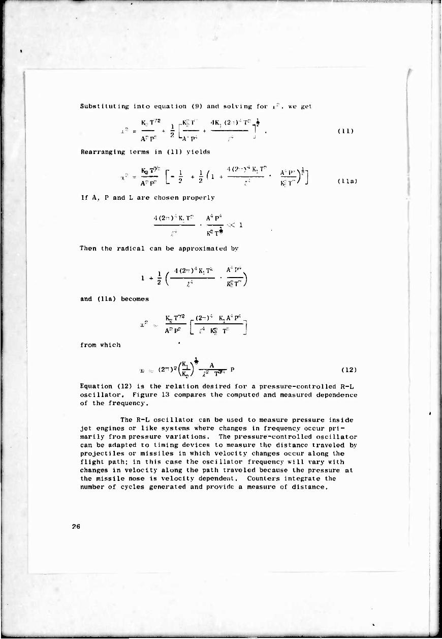
Substitutinji into equal ion (9) and solvinn for ir. we net
K T'2 r.K;;T IK, (2 ) Tr i ; ' ■ ■ iur r . (in
Ar pr " "A p' r J
RearranRinR terms in (11) yields
KsT >: r-i »n.. Ar pr L
If A. P and L are chosen properly
)(?>■* K, T
Iv T / -> (1 la)
1(2 ) K, Tr A;P'
K'T*
Then the radical can be approximated by
1 +
and (11a) becomes
from which
J
H-T l(2"rK. T' A P'
K? T" /
ICr/2 (2-)' K,^?'^ .4 ix T-r A" P- KJ Tr
J. '«">•(&) -PV - (12)
Equation (12) is the relation desired for a pressure-controlled R-L oscillator. Figure 13 compares the computed and measured dependence of the frequency.
The R-L oscillatoi can be ujed to measure pressure inside jet engines or like systems where changes in frequency occur pri- marily from pressure variations. The pressure-controlled oscillator can be adapted to timing devices to measure the distance traveled by projectiles or missiles in which velocity changes occur along the flight path; in this case the oscillator frequency will vary with changes in velocity along the path traveled because the pressure at the missile nose is velocity dependent. Counters integrate the number of cycles generated and provide a measure of distance.
?H

■
Q.
UJ
O UJ cr. u.
400
390
380
370
360
350
340
330
320
310
300
290
280
270
260
250
TEMPERATURE INSENSITIVE OSCILLATOR
L= 12" 10= 0.023" TEMPERATURE = 800F THEORETICAL CURVE EXPERIMENTAL CURVE
-L 34 36 38 40 42 44 46 48 90 PSI6
234.43 248.22 262.01 279.8 289.99 303.38 31717 330.96 344.79 KN/ Mc G
INPUT PRESSURE Figure 13. R-L pressure controlled oscillator,
experiment and theory. Comparison of 2 7
i

T^
ö. RELAXATION OSCILLATOR
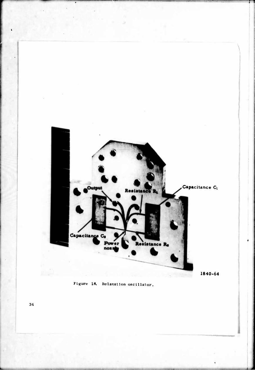
A relaxation oscillator (fift. 14) consists of a hlch'galn digital ampliiier in which part of each output is (od l)ack to its own control jet through a series R-C-R circuit. When the output is switched to either side, a pressure pulse propagates through this feedback path. When it reaches the control nozzle, it causes the output to switch to the other side. There the same kind of action occurs, completing one cycle and starting the next. The amount oi fluid intering the capacitor is detormineri by the resistor R, con- nected to the output of the capacitor and the fluid leaving it by the resistor R located at the control end ot the capacitor. Hence. Rj , Rp . and the capacitor volume determine the filling time of the capacitor, which in turn determines the frequency of the oscillator.
The oscillatory mode is excited only for pressure ratios for which the Jet spreads to occupy t lie full width of ehe output channel, for only then is a feedback achieved that will induce oscillation. In one particular case (fig. 15) the oscillator exhausts into a binary device that has a pressure below ambient in its interaction region. The amplifier control area sets a fixed load on the oscil- lator output, which causes a back pressure. The back pressure in- duces the oscillator power jet to spread and forces a portio- to feed back into the R-C-R network initialing oscillations.
The binary amplifier and the oscillator have a common supply so that a change in one is accompanied by a change in the other. This action is needed because some of the increase in flow through the oscillator nozzle is conveyed to the lower pressure region in the interaction region of the binary amplifier control ports. In addi- tion, the binary amplifier is provided with a set of bleeds located in the separation region. These bleeds exhaust anv increase in back pressure that arises when the amplifier is loaded.
In the R-L oscillator discussed, temperature insensitivity is achieved by continuously compensating the speed of wave propagation uniformly along the R-L feedback path, even though pressure insensi- tivity is sacrificed. To obtain an oscillator insensitive to both temperature and pressure, we can use the lumped R-C feedback network. The compensation for temperature insensi tivlty In the network is achieved as follows: As the temperature rises, the resistance in the network increases, which causes a reduction In flow through the feed- back loop, tending to lower the oscillation frequency. However, simultaneously, the effective tank capacitance decreases with higher temperatures, tending to increase the frequency. Hence, by adjusting the resistance of the resistors and the volume of the capacitor so that one compensat» .s the other exactly, temperature insensit 1 vl ty can be achieved. A similar arrangement is proposed for pressure
f
S8

/
o
o CO ÜL
o II
UJ
Z) c^
UJ (XL a.
Q.
N
cr O
{/)
(/) UJ cr
UJ O
i
5 o
o
o o
Q o
O O
6
$
14 o a»
o 00
O o
o
O
O ^ ^ u-
o
rO uj a:
s < tr
O Q.
UJ
CsJ
O I
o I
o m
i
(ZH) ADN3n03dJ üoivimso
UJ
O a.
s «
I c 0
a c B i
■ h >
y c 0 3 cr m h
h 0
5
o fa 3 M
29

T^
I I
a I
\
30
0
a E
— •H
— r
1
u 8 §
■-
w
3 —
<

^
insensitivity. Reference 11 discusses a mathematical analysis that establishes the criteria for temperature and pressure insensitivity by considering the flow conditions in the components of the network.
An R-C-H oscillator was built according to the design criteria established in reference 11. The width of the resistors in the feedback network were 0.032 in. for Rj and 0.010 in. for IV, and the capacitor volume was 0.306 in.3 The aspect ratio of the unit was 3:1. A binary buffer amplifier was used in testing this unit. The oscillator exhibited a frequency variation smaller than • 1 percent for a pressure ran^e from 6 to 30 psig (fiR. lö). Frequency changed less than 1 percent over a temperature range from 77° to 1750F at a pressure input of 10 pslg (fig. 17). A similar oscillator was tested to determine the sensitivity characteristics at the low gas temper- ature. For the test, dried air at -"0oF was used to prevent ice formation in the oscillator channels. The templets on which the oscillation was engraved were diffusion bonded to eliminate leakages at low temperature. The measured frequency changes at a pressure input of 10 psig did not exceed 1.5 percent for a temperature range from -58° to 70OF (fig. 18).
The development of an R-C-R oscillator insensitive to both pressure and temperature is essential for timers that must operate under a wide range of environmental conditions. The oscillator supplies a train of constant frequency pressure pulses, which are counted by cascaded frequency diveders (fig. 19). In-addition the oscillator is used as a modulator in a missile control system (fig, 20). For the control system the oscillator sets into oscil- lation a series of cascaded digital amplifiers feeding opposed lateral Jets (ref 12). Normally, these amplifiers oscillate sym- metrically and the net force output of the jets is zero. When a corrective proportional signal is introduced by a gyroscope, the balance of oscillation of the system shifts more into one output jet than into the other, resulting in a net increase in thrust in the desired direction. This is known as the pulse duration modu- lation system. It provides a proportional output from a digital system.
8. VORTEX OSCILLATOR
An oscillator whose operating principle and physical character- istics are distinctly different from the feedback types previously discussed is the vortex oscillator—in particular, the count ervortex oscillator (ref 13).
A typical countervortex oscillator consists of a straight tube with two circular chambers located at the open ends of the tube (fig. 21a). The oscillations In the unit are induced by the vortical motion of the working fluid. Spe 11 Rally, the oscillations are
31
■n
Nl
if)
a. o »- {/)
in
cr
r^- r m 1
1 H> O vp| Q. ^r ^•j UJ 9 o Q o ö x . 1— rsl b o rf»
O o i d o
cr a 6
[
o
00 rsl
rsl
rM
o
UJ
u>
O O - O
O o O 3
u
X
i
g c a
3 ■ h o > >. u c 3 C SI h
O h ^ - 5
< ;
< •
— « 3 ■
{zu) ADNinoaäd aoivniDso
-i.^

L«
'
Hi 1 % I s»
«
f o
1
d
I
J
i M
I I
S
S
1 1 K
1 §
<
8
a s m it 9) a E
c 0
B I
I a ■
>
c
c
y 6'
B mi
o u.
o 0-
o AD
o
(ZNJ *ONinö3&J &OJLV77tOSO
18
:<:<
T^
Capacitance d
CapaciUnc« Cg
1840-64
:M
Figure 18. Relaxat Ion oscl 1 lat or,

Oscillator
Binary Amplifier
SrparatinR Plate
Frequency Divider
Aspirator Channels
Binary Amplifier
Separating Plate
Capacitance Plate Output
KiKiire lit. K-C-H ostillator as time base for a timer. 1262-
35

■ c fa M a c u
M
—■
! ■ a
a E I —
1)
/: I h 3 0
c M
O fa 3
36

I Kt'uerat ed by the i nteratl ion of two vortices moving in opposite direc- tions ori^inatinfj in the tube side chambers. The vortices are pro- duced by .jet streams introduced tangent ially into the two chambers ((if;. 21b). The vortex of the upstream chamber Is initially irrota- tional and of uniform strength. However, upon entering the connecting lube, whoso cross section is smaller than that of the circular chamber, the tangential velocity of the vortex increases. This velocity in- crease imparts a high kinetic energy to the inner flow layers, which In turn is transferred to the outer layers. This energy transfer causes the vortex to become rotational at the tube exit before entering the down-stream vortex chamber. fpon emerging from the connecting tube, the rotational vortex interacts with the vortex produced in the luwnstream chamber. At a distance approximately equal to the radius of the connecting tube, the radial velocity of the upstream vortex approaches that of the vortex from the downstream chamber. When the vortical velocities of the interacting vortices are identical, the rotation at the core of the downstream "ortex tends to become unstable. I he instability at the core arises Horn viscous forces generated by the upstream rotational vortex, which constantly reverses the direc- tion of rotation of the coio of the downstream vortex. The inner core alternates between its prelcrrod direction and Its forced direction. The process of velocity reversal is periodic and causes the core to exhaust through the downstream chamber with an oscillating motion. The oscillating output contlnes as new sections of the core are sub- jected to the sa.ic periodic velocity reversal process.
Experimental studies conducted by Sarpkaya (ref 13) indicate that the frequency and amplitude of oscillation depend on the dimensions ol the connecting tube. Figure 22 shows the frequency of oscillation as a function ol the upstream vortex pressure for various connecting tube lengths. Although no particular application of such a counter- vortex oscillator has been developed, the simplicity of Its design and the stability of the oscillation over a wide range of upstream pressure makes it extremely attractive.
7. I'OSTSCKIPT
This report describes some of the most prominent fluid oscil- lators and discusses their basic application to fluldlc systems. This material has been gathered together from many sources (sec references). However, the low temperature results for the R-C-R oscillator are re- ported here for the first time. Other types of oscillators are being studied for possible application to fluldlc systems. Some have moving members, whereas others utilize the characteristics of the oscillators mentioned but with added features.
3 7

INLET 45
LA UPPERN CONNECTING TUBE ,/DOWN STREAM ^CTOCA^ L- CHAMBER
A CHAMBER O"1""
I r-
INLET
Figure 21a. Vortex oscillator schematic,
-g Figure 21b. Vortex oscillator flow model,
097-69

^ ^ 2? 9 5 5 •I II n Q Q Q
O 00
OP
s
<3 O O
JO
OÖ o
9 ÜJ GC
LU
o
£
cr h
3
i I i u x
k 0 >
« 0 h it r. a 3
u 3
CM
O u 3
ON SO
I
<7N O
o o
L X o o
± x o ±
o O ZH ADN3nD3dj indino 39
'

I
8. LTTERATTRE c 1IKI)
(1) C. Sondhaus. Ann. Phy». LP2., PI. ll'S and "J1 I (IK.-)!),
(2) R, VachsMith. Ann. Phys., KP?. H, I6P (1P04>.
(3) C.J. Caapagnuolo. Experlaental Analysla of Self~lUilntalned Oscillations of .let-Kti^t' System with a Kosonatin^ Cavity. Master's Thesis, GeorKotown (niverslty. lMt>;i.
(1) C.n. Urown. Proc. I'hys. Soc. (London), 4P. 193 (1937).
(.")) J, l.itsios. Industrial Applications ol das-UM Sonic- (k-n- erator. IKKE Transactions on Ultrasonic Eng.. Rv-pt ir63.
(<i) E. Mrun. H. M. (i. Boucher. Research <>n the Accoustic Air- Jet Generator: A Now Developaent, i. Acoustic Soc. of America, 33, S73-S83, May 1957.
(7) ('. E. Spyropou los, A Sonic Oscillator. Proc. Fluid Ampli. svmp.. Vol. in. May i^'tit. .'y-yj.
(H) j. L. Johnson, HIKII Gas Teaperatures Measured by Pluidlc Sensor. Space Aeronautics. AUK 1988. pp. 7S.
(9) J. M. Kirshner and C. •'. (ampanmiolo. A Temperature Insensi- sitive Pneumatic Oscillator and a Pi-essui-e-C'ont rol led i'neumat ic Oscil- lator, Proceedings of the Kluid Amplification S\mposium. Vol II. Oct 1.965. pp. 5-19.
(Id) J, M. Kirshmr, Editor, Fluid Ampl i ficrs, McGraw-Hill Co., New York, pp. 17").
(11) C. I. CaMpacnuolo and S. E, Oehman, Flucric Pressure and emperat ure-Insens 11 i ve Oscillator f< i- Timer Application, HDL TR-i;i81,
Feb 196K.
(12) C. J. Campajinuolo and A. B. Holmes. Experiment al Analysis of Digital Flueric Amnlifiors for Proportional Thrust Control, Second Cranfleld PluldlCS Conference. Cambridge. England, Ian 1!'(>7.
(13) T. Sparpkaya. Characteristics of Counter-Vortex Oscillators Proc. of the Fluid Amplification Symposium. Vol. 2. May IPtil. pp. 117-101.
40
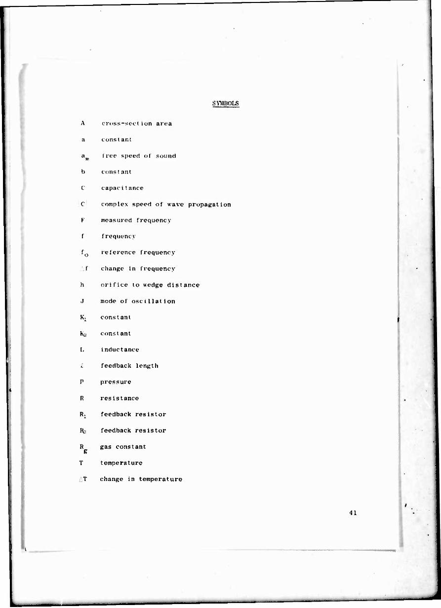
SYMBOLS
A cr(>ss-«cction area
a constant
ax free speed of sound
b conit ant
(
C
V
I
'o
f
h
•i
K;
K
I.
P
R
R i
T
T
C
capac i t ant e
complex speed of wave propagation
measured frequency
Irequcncv
leterence f requency
change in frequency
orifice to wedge distance
mode of oscillation
constant
const ant
inductance
feedback length
pressure
resistance
feedback resistor
feedback resistor
gas constant
temperature
change in temperature
41

SVMBUI..S (C'ont 'd)
T reference tempi-rat me o
t swi t eh i nj; t imc s
l' stream volooilv o
\ specific heat constant
density of the gas
viscosity of the gas
period of oscillation
Hi angular frequency
42

r UNCLASSIFIED
SjcuntyCU«»ifi«tion
DOCUMENT CONTROL DATA R&D (Stcuriir clmfllltmilatt ml till; body »I mfitmci mnd tnättlnt mutolmllan muimi W agjjjgj »ht) UM »tmtmll npoti It cl«»»«WO
ORIGIN» TINS ACTIVITY (Cotporml» mulhot)
Harry Diamond Laboratories Washington, D. C. 20438
M. mt*om iicuniTv CkAtaincATiON
UNCUSSIFIED a», a mourn
1 HtPOKT TITLI
REVIEW OF SOME FLUID OSCILLATORS
OCtCRiVTivt NOTCt (Tyf oI repoti antf Inclumir» Imitt)
iTMORiti rnraxw**, mUmm Ittlilml, Imml itmmtm)
Carl J. Canpagnuolo Henry C. Lee
• noonr o»Tt
■• COMTRAC ' OK «RANT NO.
». RROjtc T NO CA-IT061102A33B
«. AMCMS Code: 5011.11.71200
* HDL Proj. No. 41100 10. Oil
?•. TOTAL NO 6F RA«KS
56 lb. NO OP Rin
13
TR-1438
OTHER Rtl Ihl* iwpert)
JUI (Anr
This document has been approved for public release and sale; its distribution is unlimited.
JTT
It. IRONfORINa MILITARY ACTIVITY
AMC
Fluid oscillators of various types have been developed and applied to fluidlc systems for sensing or missile control. The operating characteristics of these oscil- lators, including the dependence of the frequency on the stagnation pressure and temperature, are a function of the type of return loop employed for maintaining oscil- lations.
This report discuages and summarizes the operating principles, design, frequency variation, and applications of some of the most prominent oscillators such as: The sonic, lumped R-C-R and L-R, edgetone, ringtone, and vortex oscillators.
An FMW 4 A 11 MSRLACBa DO FORM IA»t, I JAM «4. «MICH I« fj^ , MOv ««14 /3 OR»OL«TB POM ARMY u««. UNCLASSIFIED
~ locurily ClataincaUo«
55

UNCLASSIFIED Wmemitf CI««»»lc«U—
Fluerlcs
Sonic oscillator
Lumped R-C-R oscillator
Li'mped L-R oscillator
Edgetone oscillator
Rln^tone oscillator
Vortex oscillator
Stagnation pressure
Fluid temperature
Frequency
8 1
8 3
8 3
1 3
8 3
8 3
8 3
6 3
6 3
7 3
56 UNCLASSIFIED tacurltir Ctaaalflcatlon