000885spc-02 - rh-45-hacw two-stage r410a 230 …€¢ installation and service manual ... for...
TRANSCRIPT

Maritime Geothermal Ltd. P.O. Box 2555 Petitcodiac, N.B. E4Z 6H4
Email: [email protected] Web: www.nordicghp.com
Document Number: 000885SPC-02
REVISION DATE: 25 MAY 2009
Liquid to Air Geothermal Heat Pumps
ENGINEERING SPECIFICATIONS NORDIC® RH-45-HACW-P-1T-*-SDE*F
Horizontal Two-Stage R410a Model Size 45 (Nominal 3 Ton)
Reversing (Heating AND Cooling) Domestic Hot Water (desuperheater)
230-1-60VAC
25 MAY 2009 Page 2 000885SPC-02
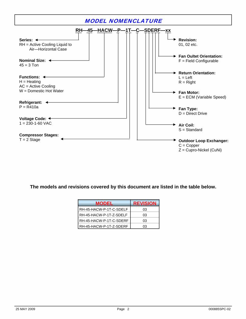
The models and revisions covered by this document are listed in the table below.
MODEL REVISION RH-45-HACW-P-1T-C-SDELF 03 RH-45-HACW-P-1T-Z-SDELF 03 RH-45-HACW-P-1T-C-SDERF 03 RH-45-HACW-P-1T-Z-SDERF 03
Series: RH = Active Cooling Liquid to Air—Horizontal Case
Nominal Size: 45 = 3 Ton
Functions: H = Heating AC = Active Cooling W = Domestic Hot Water
Refrigerant: P = R410a
Voltage Code: 1 = 230-1-60 VAC Air Coil:
S = Standard
Fan Type: D = Direct Drive
Fan Motor: E = ECM (Variable Speed)
Return Orientation: L = Left R = Right
Revision: 01, 02 etc.
RH—45—HACW—P—1T—C—SDERF—xx
MODEL NOMENCLATURE
Outdoor Loop Exchanger: C = Copper Z = Cupro-Nickel (CuNi)
Fan Oultet Orientation: F = Field Configurable
Compressor Stages: T = 2 Stage

25 MAY 2009 Page 3 000885SPC-02
The geothermal heat pump described in this specification document comes with the following features: • 20ga satin galvanized case with welded reinforcing channel stiffeners and corner posts • Corner mounting points for suspension applications • Powder coat finish • Acoustically insulated cabinet (1/2” thick) • ECM fan motor with single side access. • Left or right return (must be specified when ordered) • Field configurable fan outlet orientation (side or end) • Reversible air filter rack • Stainless steel condensate drip tray • Clear condensate drain with 3/4” PVC socket • Multi-circuit high efficiency air-coil • Refrigeration service ports located outside unit (1/4” Schrader) • Insulated coaxial heat exchangers and piping available in copper or cupro-nickel • 1” heavy duty brass FPT fittings for Outdoor Loop connections • Two-stage Scroll compressor with hard start kit on single phase models • Suction line accumulator • Liquid line filter-drier • Liquid line sight glass • Balanced port Thermostatic Expansion Valve with internal bleed • 4-way reversing valve • High and low pressure safety controls • Control board with anti-short cycle timer, three re-start attempts and permanent lockout mode • Electrical box layout and schematic diagrams • Installation and service manual • Double wall Domestic Hot Water desuperheater suitable for potable water connections • Bronze head ECM circulator for domestic hot water circuit uses less than half the power of traditional cir-
culating pumps, and allows motor replacement without tools • 1/2” heavy duty brass FPT fittings for Domestic Hot Water connections
NORDIC® DESIGN FEATURES LIST
OPTIONAL EQUIPMENT
The following is a list of optional equipment that may be ordered with the geothermal heat pump: • 3-stage heat 2-stage cool programmable thermostat • Circulator pump module with loop / unit isolation valves (230VAC) for ground loop applications • Various adapters for unit and loop connections to pump module • 1” Electronic Ball Valve (24VAC) & wiring harness for groundwater applications • Electric plenum heater

25 MAY 2009 Page 4 000885SPC-02
Optional side or end mount fan orientation configurable on site
Heavy duty case constructed of satin galvanized panels with welded reinforcing channel stiffeners and corner posts.
Cabinet completely insulated with 1/2” acoustic insulation.
High efficiency Copeland® Scroll
two-stage compressor
Optional water valve for ground water installations.
CSA certified for electrical safety to CSA 22.2 No 236-05.
Balanced port TXV with internal bleed
4-way reversing valve
Hard Start kit on all single phase models.
Stainless Steel condensate drip tray.
Heavy duty electri-cal components.
Contactor rated for 2 million cycles.
Field replaceable variable speed ECM fan motor with ball bearings and resilient mounting bracket
Bi-flow filter drier
Insulated High Efficiency
Turbotec® coaxial heat exchanger. Resistant to acci-dental freezing
High & Low Refrigerant
access ports
Bronze head domestic hot water circulator pump. Thermostat: ON @ 120°F OFF @ 140°F
Suction accumulator
Sight glass
Clear condensate drain with 3/4” PVC socket
NORDIC® DESIGN FEATURES (Right Hand Return shown)
Control board with lock-out indi-cator and anti-short cycle timer.
1” Brass FPT Connections
1/2” Brass FPT Connections for DHW
Corner braces with 1/2” holes for suspension Mounting applications
MAJOR COMPONENTS (Right Hand Return shown)
Reversible filter rack
Legend 1. Multi-circuit high efficiency air coil 2. Oversize coaxial heat exchanger 3. Direct drive fan with ECM motor 7. Copeland Two stage compressor 8. Balance port TXV with internal bleed 9. Bi-flow filter drier 10. Accumulator 11. Sight Glass 12. 4-way reversing valve 13. Bronze head DHW circulator

25 MAY 2009 Page 5 000885SPC-02
FRONT PERSPECTIVE VIEWS
Left Return
Right Return

25 MAY 2009 Page 6 000885SPC-02
Front View
Back View
CASE DETAILS—Left Hand Return (Size 25 to 45)

25 MAY 2009 Page 7 000885SPC-02
Bottom View
Right Side View
Left Side View
CASE DETAILS—Left Hand Return (Size 25 to 45) - continued

25 MAY 2009 Page 8 000885SPC-02
Front View
Back View
CASE DETAILS—Right Hand Return (Size 25 to 45)

25 MAY 2009 Page 9 000885SPC-02
Bottom View
Right Side View
Left Side View
CASE DETAILS—Right Hand Return (Size 25 to 45) - continued

25 MAY 2009 Page 10 000885SPC-02
14. Airflow Selection Board (-12%,-6%, Nom.,+6%) 15. Compressor Contactor. 16. Potential Relay. 17. Plenum Heat Relay. 18. Run capacitor. 19. Start Capacitor
20. Class II control transformer with manual reset. 21. Ground Loop Pump Module Connection. 22. Thermostat Terminal strip. 23. Ground Lug. 24. Safety control board.
Legend
Heat Pump Electrical Information Nomenclature
Identifier Compressor Fan FLA MCA Maximum Fuse/Breaker
Minimum Wire Size
V-ø-Hz MIN MAX RLA LRA RLA Amps Amps Amps ga 1 230-1-60 207 253 18.6 82 3.5 26.9 31.6 40 #8-3
Power Supply
Unit Weight Refrigerant Charge Lbs. kg Lbs. kg 420 190 R410a 5.5 2.5
Refrigerant Type
ELECTRICAL BOX LAYOUT
MINIMUM AND MAXIMUM OPERATING TEMPERATURES*
ELECTRICAL SPECIFICATIONS
MISCELLANEOUS INFORMATION
Loop Parameter Mode (°F) (°C) Note
Outdoor Minimum ELT Heating / Cooling 39 4 Ground water system. Minimum ELT Heating / Cooling 23 -5 Ground loop system. Adequate freeze protection required. Maximum ELT Cooling 110 43 Ground loop system. Minimum EAT Heating / Cooling 60 16 Reduce flow if necessary during heating startup. Maximum EAT Heating 80 27
* Values in this table are for rated liquid and airflow values.
Indoor (Duct)
Left Return Right Return

25 MAY 2009 Page 11 000885SPC-02
ELECTRICAL DIAGRAMS (230-1-60)

25 MAY 2009 Page 12 000885SPC-02
ELECTRICAL DIAGRAMS (230-1-60) - continued

25 MAY 2009 Page 13 000885SPC-02
ELECTRICAL DIAGRAMS (230-1-60) - continued

25 MAY 2009 Page 14 000885SPC-02
REFRIGERATION CIRCUIT DIAGRAMS

25 MAY 2009 Page 15 000885SPC-02
REFRIGERATION CIRCUIT DIAGRAMS (continued)
25 MAY 2009 Page 16 000885SPC-02
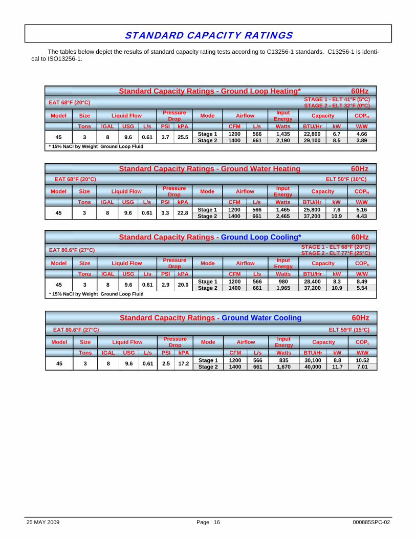
The tables below depict the results of standard capacity rating tests according to C13256-1 standards. C13256-1 is identi-cal to ISO13256-1.
Standard Capacity Ratings - Ground Loop Heating* 60Hz EAT 68°F (20°C) STAGE 1 - ELT 41°F (5°C)
STAGE 2 - ELT 32°F (0°C) Model Size Liquid Flow Pressure
Drop Mode Airflow Input Energy Capacity COPH
Tons IGAL USG L/s PSI kPA CFM L/s Watts BTU/Hr kW W/W
45 3 8 9.6 0.61 3.7 25.5 Stage 1 1200 566 1,435 22,800 6.7 4.66 Stage 2 1400 661 2,190 29,100 8.5 3.89
* 15% NaCl by Weight Ground Loop Fluid
Standard Capacity Ratings - Ground Water Heating 60Hz EAT 68°F (20°C) ELT 50°F (10°C)
Model Size Liquid Flow Pressure Drop Mode Airflow Input
Energy Capacity COPH
Tons IGAL USG L/s PSI kPA CFM L/s Watts BTU/Hr kW W/W
45 3 8 9.6 0.61 3.3 22.8 Stage 1 1200 566 1,465 25,800 7.6 5.16 Stage 2 1400 661 2,465 37,200 10.9 4.43
Standard Capacity Ratings - Ground Loop Cooling* 60Hz EAT 80.6°F (27°C) STAGE 1 - ELT 68°F (20°C)
STAGE 2 - ELT 77°F (25°C) Model Size Liquid Flow Pressure
Drop Mode Airflow Input Energy Capacity COPc
Tons IGAL USG L/s PSI kPA CFM L/s Watts BTU/Hr kW W/W
45 3 8 9.6 0.61 2.9 20.0 Stage 1 1200 566 980 28,400 8.3 8.49 Stage 2 1400 661 1,965 37,200 10.9 5.54
* 15% NaCl by Weight Ground Loop Fluid
Standard Capacity Ratings - Ground Water Cooling 60Hz EAT 80.6°F (27°C) ELT 59°F (15°C)
Model Size Liquid Flow Pressure Drop Mode Airflow Input
Energy Capacity COPc
Tons IGAL USG L/s PSI kPA CFM L/s Watts BTU/Hr kW W/W
45 3 8 9.6 0.61 2.5 17.2 Stage 1 1200 566 835 30,100 8.8 10.52 Stage 2 1400 661 1,670 40,000 11.7 7.01
STANDARD CAPACITY RATINGS

25 MAY 2009 Page 17 000885SPC-02
Heating Mode RH-45-HACW-P-1T Nominal 3 ton R410a 60 Hz
Source Data (Outdoor Loop) Power Consumption Sink Data (Indoor Loop) ELT Evap.
Temp Flow LLT Delta T HAB Compressor Fan* Effective COPh EAT Cond. Temp.
Air Flow LAT Delta T Net
Output °F °F Igpm °F °F BTU/Hr Watts Amps Watts Watts W/W °F °F CFM °F °F BTU/Hr °C °C L/min °C °C Watts °C °C L/s °C °C Watts
26.0 15 8.0 21.8 4.2 20,108 1,993 9.2 135 2,136 3.72 68 103 1,400 85.9 17.9 27,106 -3.3 -9.4 36.2 -5.6 2.3 5,891 20.0 39.4 661 29.9 9.9 7,942 32.0 20 8.0 27.5 4.5 21,898 2,050 9.5 135 2,193 3.89 68 105 1,400 87.2 19.2 29,091 0.0 -6.7 36.2 -2.5 2.5 6,416 20.0 40.6 661 30.7 10.7 8,524 38.0 25 8.0 33.1 4.9 23,818 2,107 9.7 135 2,250 4.06 68 107 1,400 88.6 20.6 31,207 3.3 -3.9 36.2 0.6 2.7 6,979 20.0 41.7 661 31.4 11.4 9,144 44.0 30 8.0 38.7 5.3 25,701 2,192 10.2 135 2,335 4.19 68 110 1,400 90.0 22.0 33,382 6.7 -1.1 36.2 3.7 3.0 7,530 20.0 43.3 661 32.2 12.2 9,781 47.0 35 8.0 41.2 5.8 28,591 2,242 10.4 135 2,381 4.48 68 112 1,400 92.0 24.0 36,436 8.3 1.7 36.2 5.1 3.2 8,377 20.0 44.4 661 33.4 13.4 10,676 53.0 40 8.0 46.8 6.2 30,756 2,332 10.9 135 2,471 4.61 68 115 1,400 93.7 25.7 38,907 11.7 4.4 36.2 8.2 3.4 9,011 20.0 46.1 661 34.3 14.3 11,400 59.0 45 8.0 52.3 6.7 33,262 2,395 11.2 135 2,534 4.81 68 117 1,400 95.5 27.5 41,627 15.0 7.2 36.2 11.3 3.7 9,746 20.0 47.2 661 35.3 15.3 12,197 65.0 50 8.0 57.8 7.2 35,919 2,460 11.5 135 2,599 5.02 68 119 1,400 97.4 29.4 44,506 18.3 10.0 36.2 14.3 4.0 10,524 20.0 48.3 661 36.3 16.3 13,040
* @ 37.3Pa (0.15inH2o) Ext. Static Compressor: ZPS30K4E-PFV
Cooling Mode RH-45-HACW-P-1T R410a 60 Hz
Source Data (Indoor Loop) Power Consumption Sink Data (Outdoor Loop) EAT Evap.
Temp Airflow LAT Delta T HAB Compressor Fan* Effective Effi-ciency ELT Cond.
Temp. Flow LLT Delta T Rejection
°F °F CFM °F °F BTU/Hr Watts Amps Watts Watts EER °F °F Igpm °F °F BTU/Hr °C °C L/s °C °C Watts COPc °C °C L/min °C °C Watts
80.6 40 1,400 60.3 20.3 41,083 1,381 5.9 150 1,528 26.9 53 70 8.0 62.6 9.6 46,309 27.0 4.4 661 15.7 11.3 12,037 7.88 11.7 21.1 36 17.0 5.4 13,568 80.6 40 1,400 60.7 19.9 40,155 1,497 6.4 150 1,644 24.4 58 75 8.0 67.5 9.5 45,775 27.0 4.4 661 16.0 11.0 11,765 7.16 14.4 23.9 36 19.7 5.3 13,412 80.6 41 1,400 60.8 19.8 39,927 1,614 6.9 150 1,761 22.7 63 80 8.0 72.6 9.6 45,949 27.0 5.0 661 16.0 11.0 11,699 6.64 17.2 26.7 36 22.5 5.3 13,463 80.6 42 1,400 61.0 19.6 39,657 1,734 7.4 150 1,881 21.1 68 85 8.0 77.6 9.6 46,088 27.0 5.6 661 16.1 10.9 11,619 6.18 20.0 29.4 36 25.3 5.3 13,504 80.6 43 1,400 61.9 18.7 37,777 1,749 7.9 150 1,891 20.0 74 90 8.0 83.2 9.2 44,256 27.0 6.1 661 16.6 10.4 11,068 5.85 23.3 32.2 36 28.5 5.1 12,967 80.6 43 1,400 62.4 18.2 36,763 1,869 8.4 150 2,011 18.3 79 95 8.0 88.1 9.1 43,654 27.0 6.1 661 16.9 10.1 10,772 5.36 26.1 35.0 36 31.2 5.1 12,791 80.6 44 1,400 62.6 18.0 36,381 1,995 9.0 150 2,137 17.0 84 100 8.0 93.1 9.1 43,703 27.0 6.7 661 17.0 10.0 10,659 4.99 28.9 37.8 36 33.9 5.1 12,805 80.6 44 1,400 63.1 17.5 35,309 2,128 9.6 150 2,270 15.6 89 105 8.0 98.0 9.0 43,083 27.0 6.7 661 17.3 9.7 10,346 4.56 31.7 40.6 36 36.7 5.0 12,623
* @ 37.3Pa (0.15inH2o) Ext. Static Compressor: ZPS30K4E-PFV
Sensible
BTU/Hr Watts
30,813 9,028
30,116 8,824
29,945 8,774
29,743 8,715
28,332 8,301
27,573 8,079
27,285 7,995
26,482 7,759
Latent
BTU/Hr Watts
10,271 3,009
10,039 2,941 9,982 2,925 9,914 2,905 9,444 2,767 9,191 2,693 9,095 2,665 8,827 2,586
CAPACITY RATINGS

25 MAY 2009 Page 18 000885SPC-02
Heating Mode (Part Load) RH-45-HACW-P-1T R410a 60 Hz
Source Data (Outdoor Loop) Power Consumption Sink Data (Indoor Loop) ELT Evap.
Temp Flow LLT Delta T HAB Compressor Fan* Effective COPh EAT Cond. Temp.
Air Flow LAT Delta T Net
Output °F °F Igpm °F °F BTU/Hr Watts Amps Watts Watts W/W °F °F CFM °F °F BTU/Hr °C °C L/min °C °C Watts °C °C L/s °C °C Watts
27.0 20 7.0 23.9 3.1 13,164 1,197 5.6 70 1,278 3.97 68 93 1,000 84.0 16.0 17,300 -2.8 -6.7 31.6 -4.5 1.7 3,857 20.0 33.9 472 28.9 8.9 5,069 33.0 25 7.0 29.5 3.5 14,605 1,220 5.7 70 1,301 4.24 68 95 1,000 85.4 17.4 18,820 0.6 -3.9 31.6 -1.4 1.9 4,279 20.0 35.0 472 29.7 9.7 5,514 39.0 30 7.0 35.2 3.8 16,147 1,242 5.8 70 1,323 4.53 68 97 1,000 86.9 18.9 20,436 3.9 -1.1 31.6 1.8 2.1 4,731 20.0 36.1 472 30.5 10.5 5,988 45.0 35 7.0 40.8 4.2 17,675 1,286 6.0 70 1,367 4.74 68 100 1,000 88.4 20.4 22,116 7.2 1.7 31.6 4.9 2.3 5,179 20.0 37.8 472 31.3 11.3 6,480 49.0 40 7.0 44.4 4.6 18,518 1,247 6.2 70 1,321 5.06 68 103 1,000 89.1 21.1 22,827 9.4 4.4 31.6 6.9 2.6 5,426 20.0 39.4 472 31.7 11.7 6,688 55.0 45 7.0 50.0 5.0 20,300 1,270 6.4 70 1,344 5.38 68 105 1,000 90.8 22.8 24,685 12.8 7.2 31.6 10.0 2.8 5,948 20.0 40.6 472 32.7 12.7 7,233 61.0 50 7.0 55.5 5.5 22,204 1,294 6.5 70 1,368 5.71 68 107 1,000 92.6 24.6 26,673 16.1 10.0 31.6 13.1 3.1 6,506 20.0 41.7 472 33.7 13.7 7,815 67.0 55 7.0 61.0 6.0 24,235 1,322 6.6 70 1,396 6.05 68 109 1,000 94.6 26.6 28,797 19.4 12.8 31.6 16.1 3.3 7,101 20.0 42.8 472 34.8 14.8 8,437
* @ 37.3Pa (0.15inH2o) Ext. Static Compressor: ZPS30K4E-PFV
Cooling Mode (Part Load) R-45-HACW-P-1T R410a 60 Hz
Source Data (Indoor Loop) Power Consumption Sink Data (Outdoor Loop) EAT Evap.
Temp Airflow LAT Delta T HAB Compressor Fan* Effective Effi-ciency ELT Cond.
Temp. Flow LLT Delta T Rejection
°F °F CFM °F °F BTU/Hr Watts Amps Watts Watts EER °F °F Igpm °F °F BTU/Hr °C °C L/s °C °C Watts COPc °C °C L/min °C °C Watts
80.6 44 1,200 62.4 18.2 31,562 596 3.2 80 680 46.5 48 60 8.0 55.1 7.1 33,869 27.0 6.7 566 16.9 10.1 9,248 13.64 8.9 15.6 36 12.8 3.9 9,923 80.6 44 1,200 62.8 17.8 30,904 669 3.5 80 753 41.2 53 65 8.0 60.0 7.0 33,459 27.0 6.7 566 17.1 9.9 9,055 12.06 11.7 18.3 36 15.5 3.9 9,803 80.6 44 1,200 63.2 17.4 30,213 741 3.9 80 825 36.7 58 70 8.0 64.9 6.9 33,015 27.0 6.7 566 17.3 9.7 8,852 10.76 14.4 21.1 36 18.3 3.8 9,673 80.6 45 1,200 63.2 17.4 30,156 814 4.3 80 898 33.6 63 75 8.0 69.9 6.9 33,209 27.0 7.2 566 17.3 9.7 8,836 9.86 17.2 23.9 36 21.1 3.8 9,730 80.6 45 1,200 64.2 16.4 28,413 894 4.7 80 977 29.0 68 80 8.0 74.6 6.6 31,737 27.0 7.2 566 17.9 9.1 8,325 8.49 20.0 26.7 36 23.7 3.7 9,299 80.6 45 1,200 64.6 16.0 27,644 972 5.1 80 1,055 26.1 73 85 8.0 79.5 6.5 31,234 27.0 7.2 566 18.1 8.9 8,100 7.66 22.8 29.4 36 26.4 3.6 9,152 80.6 46 1,200 64.8 15.8 27,458 1,053 5.5 80 1,136 24.1 78 90 8.0 84.5 6.5 31,326 27.0 7.8 566 18.2 8.8 8,045 7.06 25.6 32.2 36 29.2 3.6 9,178 80.6 46 1,200 65.2 15.4 26,621 1,140 5.9 80 1,223 21.7 83 95 8.0 89.4 6.4 30,785 27.0 7.8 566 18.5 8.5 7,800 6.36 28.3 35.0 36 31.9 3.6 9,020
* @ 37.3Pa (0.15inH2o) Ext. Static Compressor: ZPS30K4E-PFV
Sensible
BTU/Hr Watts
23,672 6,936
23,178 6,791
22,660 6,639
22,617 6,627
21,309 6,244
20,733 6,075
20,593 6,034
19,966 5,850
Latent
BTU/Hr Watts 7,891 2,312 7,726 2,264 7,553 2,213 7,539 2,209 7,103 2,081 6,911 2,025 6,864 2,011 6,655 1,950
CAPACITY RATINGS - continued

25 MAY 2009 Page 19 000885SPC-02
NOMINAL AIRFLOW SETTING (MED)
STAGE 2 STAGE 1 FAN ONLY (Recirculation)
Model Nom.Size Full Reduced* Full Reduced* Full Reduced*
Tons CFM L/s CFM L/s CFM L/s CFM L/s CFM L/s CFM L/s
25 2 800 378 680 321 680 321 578 273 448 211 381 180 45 3 1200 566 1020 481 1030 486 876 413 672 317 571 270 55 4 1500 708 1275 602 1240 585 1054 497 840 396 714 337 65 5 1900 897 1615 762 1540 727 1309 618 1064 502 904 427 75 6 2100 991 1785 842 1660 783 1411 666 1176 555 1000 472
-6% AIRFLOW SETTING (LOW)
STAGE 2 STAGE 1 FAN ONLY (Recirculation)
Model Nom.Size Full Reduced* Full Reduced* Full Reduced*
Tons CFM L/s CFM L/s CFM L/s CFM L/s CFM L/s CFM L/s
25 2 752 355 639 302 639 302 543 256 421 199 358 169 45 3 1128 532 959 453 968 457 823 388 632 298 537 253 55 4 1410 665 1199 566 1166 550 991 468 790 373 671 317 65 5 1786 843 1518 716 1448 683 1230 581 1000 472 850 401 75 6 1974 932 1678 792 1560 736 1326 626 1105 522 940 443
+6% AIRFLOW SETTING (HIGH)
STAGE 2 STAGE 1 FAN ONLY (Recirculation)
Model Nom.Size Full Reduced* Full Reduced* Full Reduced*
Tons CFM L/s CFM L/s CFM L/s CFM L/s CFM L/s CFM L/s
25 2 848 400 721 340 721 340 613 289 475 224 404 191 45 3 1272 600 1081 510 1092 515 928 438 712 336 605 286 55 4 1590 750 1352 638 1314 620 1117 527 890 420 757 357 65 5 2014 951 1712 808 1632 770 1388 655 1128 532 959 452 75 6 2226 1051 1892 893 1760 830 1496 706 1400 661 1190 562
+12% AIRFLOW SETTING (MAX)
STAGE 2 STAGE 1 FAN ONLY (Recirculation)
Model Nom.Size Full Reduced* Full Reduced* Full Reduced*
Tons CFM L/s CFM L/s CFM L/s CFM L/s CFM L/s CFM L/s
25 2 896 423 762 359 762 359 647 306 502 237 426 201 45 3 1344 634 1142 539 1154 544 981 463 753 355 640 302 55 4 1680 793 1428 674 1389 655 1180 557 941 444 800 377 65 5 2128 1004 1809 854 1725 814 1466 692 1192 562 1013 478 75 6 2352 1110 1999 944 1859 877 1580 746 1317 622 1120 528
NOTES: Unit sizes 25, 45 and 55 nominal value up to 0.50 inH2o, sizes 65 and 75 up to 0.70inH2o *To obtain the REDUCED airflow values use a dry contact to connect AR1 to AR2 on the terminal strip
ECM Fan Airflow Tables
INFORMATION TAKEN FROM DOCUMENT 000527INF-03

25 MAY 2009 Page 20 000885SPC-02
LIMITED WARRANTY
MARITIME GEOTHERMAL LTD. warrants that its geothermal heat pumps shall be free from defects in materials and workmanship for a period of FIVE (5) YEARS after the date of installation or for a period of FIVE (5) YEARS AND SIXTY (60) DAYS after the date of shipment, whichever occurs first. This warranty covers all internal components of the heat pump. An allowance is also provided for labour. Please see labor allowance schedule for information pertaining to labor coverage. MARITIME GEOTHERMAL LTD. shall, at its option, repair or replace any part covered by this warranty. Defective parts shall be returned to MARITIME GEOTHERMAL LTD., transportation charges prepaid. Replacement or repaired parts and components are warranted only for the remaining portion of the original warranty period.
This warranty is subject to the following conditions: 1. The geothermal heat pump must be properly installed and maintained in
accordance with MARITIME GEOTHERMAL LTD. guidelines. 2. The installer must complete the Startup Record and return it to MARITIME
GEOTHERMAL LTD. within 21 days of unit installation. 3. For new construction, it is the responsibility of the building or general
contractor to supply temporary heat to the structure prior to occupancy. Geothermal heat pumps are designed to provide heat only to the completely finished and insulated structure. Startup of the unit shall not be scheduled prior to completion of construction and final duct installation for validation of this warranty.
4. It is the customer's responsibility to supply the proper quantity and quality of
water or properly sized ground loop with adequate freeze protection.
If a geothermal heat pump manufactured by MARITIME GEOTHERMAL LTD. fails to conform to this warranty, MARITIME GEOTHERMAL LTD.'s sole and exclusive liability shall be, at its option, to repair or replace any part or component which is returned by the customer during the applicable warranty period set forth above, provided that (1) MARITIME GEOTHERMAL LTD. is promptly notified in writing upon discovery by the customer that such part or component fails to conform to this warranty; (2) the customer returns such part or component to MARITIME GEOTHERMAL LTD., transportation charges prepaid, within (30) thirty days of failure, and (3) MARITIME GEOTHERMAL LTD.'s examination of such component discloses to its satisfaction that such part or component fails to conform to this warranty and the alleged defects were not caused by accident, misuse, neglect, alteration, improper installation, repair or improper testing. MARITIME GEOTHERMAL LTD. will not be responsible for any consequential damages or labour costs incurred. In additional, MARITIME GEOTHERMAL LTD. will not be responsible for the cost of replacement parts purchased from a third party.