001-045 alfa 159 sw gb -...
TRANSCRIPT

OWNER’S MANUAL ALFA159
SERVICE
ENGLISH
Alfa 159 cop. LUM GB 1-10-2007 9:40 Pagina 1


This booklet describes all the versions of the Alfa 159, so you should only consider the infor-mation concerning the trim level, engine and version purchased by you.
Dear Customer,
thank you for choosing Alfa Romeo.
Your Alfa 159 has been designed to guarantee the safety, comfort and driving pleasure typical of Alfa Romeo.
This booklet will help you to get to know the characteristics and operation of your car.
The following pages contain all the indications necessary for you to be able to maintain the high standards of per-formance, quality, safety and respect for the environment which characterize this Alfa 159.
The enclosed Warranty Booklet also contains the regulations, the warranty certificate and a guide to the services of-fered by Alfa Romeo.
Services which are essential and precious because, when you purchase an Alfa Romeo you are not only acquiring acar, but the tranquillity that comes from knowing that an efficient, willing and widespread organization is at your ser-vice for any assistance problems you may have.
Have a good trip.

MUST BE READ!
REFUELLING
Petrol engines: only refuel with unleaded petrol with octane rating (RON) not less than 95.
Diesel engines: only refuel with diesel fuel conforming to the European specification EN590. The use ofother products or mixtures may irreparably damage the engine with invalidation of the warranty due to thedamage caused.
K
ENGINE STARTINGPetrol engines: make sure that the handbrake is engaged; set the gearshift lever to neutral; fit the electronic key in-
to the ignition switch to the stop limit; fully depress the clutch or the brake pedal without pressing the accelerator; pressbutton START/STOP and release it as soon as the engine has started.
Diesel engines: make sure that the handbrake is engaged; set the gearshift lever to neutral; fit the electronic key in-to the ignition switch to the stop limit; wait for the Y and m warning lights to go off; fully depress the clutch or orthe brake pedal without pressing the accelerator; press button START/STOP and release it as soon as the engine hasstarted.
PARKING ON FLAMMABLE MATERIAL
While working, the catalyst develops a very high temperature. Do not park the car over grass, dry leaves, pineneedles or any other inflammable materials: risk of fire.�
RESPECTING THE ENVIRONMENT
A system for continuously monitoring emission system components to ensure greater environmental protec-tion is fitted in your car.

ELECTRICAL ACCESSORIES
If, after buying the car, you decide to add electrical accessories (that will gradually drain the battery), contact Al-fa Romeo Authorized Services. They can calculate the overall electrical requirement and check that the car’s elec-tric system can support the required load.
�
CODE CARD
Keep the code card in a safe place, not in the car.
SCHEDULED SERVICING
Correct maintenance of the car is essential for ensuring it stays in tip-top condition and safeguards its safety fea-tures, its environmental friendliness and low running costs for a long time to come.
THE OWNER’S MANUAL CONTAINS…
…information, tips and important warnings regarding the safe, correct driving of your car, and its mainte-nance. Pay particular attention to the symbols" (personal safety) # (environmental protection) â (car well-be-ing).

Any queries concerning servicing should be forwarded to the showroom from which the car was purchased, the sub-sidiary company or to our branch offices or any point of the Alfa Romeo Network.
Warranty Booklet
The Warranty Booklet is delivered together with every new car and contains the regulations tied to the services giv-en by Alfa Romeo Services and to the warranty conditions.
Correctly carrying out the scheduled services specified by the manufacturer is the best way to maintain the perfor-mance, safety characteristics and low running costs of your car. It is also necessary to maintain warranty cover.
“Service” guideThis contains the Alfa Romeo Authorized Services. The services can be recognized by the presence of the Alfa Romeobadge and logo.
The Alfa Romeo organization in Italy can be found in the telephone book under the letter “A” Alfa Romeo.
Not all the models described in this booklet are available in all countries. Only some of the fittings described in thisbooklet are fitted as standard to the car. The list of available accessories should be requested from the Alfa RomeoDealers.

THE SYMBOLS USED IN THIS BOOKLET
The symbols illustrated in these pages show the subjects which should, in particular, be closely studied.
Warning: partially or fully ignoring these rules may lead to serious injury.
This indicates the correct procedures to be followed to prevent the car from damaging the environment.
Warning: partially or fully ignoring theserules may lead to serious damage being caused to the car which, in somecircumstances, may cause forfeiture of thewarranty cover.
The texts, illustrations and specifications given in this booklet refer to the car at the time of going to press. As part of our ongoing striving to improve our products, Alfa Romeo may introduce technical changes during production, there-
fore the specifications and fittings may be altered without prior notice. For details on this subject, please apply to the manufacturer's sales network.
PERSONALSAFETY
PROTECTING THEENVIRONMENT CAR SAFETY

6
SAFE
TYDE
VICES
WARN
ING
LIGHT
S AN
D ME
SSAG
ESIN
AN
EMER
GENC
YCA
RMA
INTE
NANC
ETE
CHNI
CAL
SPEC
IFICA
TIONS
INDE
XCO
RREC
T USE
OF
THE C
AR
DASH
BOAR
DAN
DCO
NTRO
LS DDAASSHHBBOOAARRDD AANNDD CCOONNTTRROOLLSSCRUISE CONTROL .............................................. 76CEILING LIGHTS ................................................. 78CONTROLS ........................................................ 81INTERIOR FITTINGS............................................. 83SUNROOF ......................................................... 93DOORS ............................................................ 96POWER WINDOWS ............................................ 99BOOT ............................................................... 101BONNET............................................................ 105ROOF RACK/SKI RACK ....................................... 106HEADLIGHTS...................................................... 106ABS SYSTEM .................................................... 108VDC SYSTEM .................................................... 110EOBD SYSTEM .................................................. 115SOUND SYSTEM PRESETTING .............................. 116ACCESSORIES PURCHASED BY THE OWNER .......... 117INSTALLATION OF ELECTRIC/ELECTRONIC DEVICES .. 117PARKING SENSORS ............................................ 118TYRE PRESSURE MONITORING SYSTEM(T.P.M.S.) ......................................................... 122AT THE FILLING STATION ..................................... 125
PROTECTING THE ENVIRONMENT ......................... 127
DASHBOARD...................................................... 7
INSTRUMENT PANEL .......................................... 8
SYMBOLS ........................................................ 10
ALFA ROMEO CODE SYSTEM................................ 10
ELECTRONIC KEY ............................................... 12
ALARM ............................................................ 17
IGNITION DEVICE................................................ 19
INSTRUMENTS................................................... 21
MULTIFUNCTION DISPLAY.................................... 25
RECONFIGURABLE MULTIFUNCTION DISPLAY .......... 30
SEATS .............................................................. 45
HEAD RESTRAINTS.............................................. 48
STEERING WHEEL .............................................. 49
REARVIEW MIRRORS .......................................... 50
CLIMATE CONTROL SYSTEM ................................ 53
MANUAL CLIMATE CONTROL SYSTEM ................... 55
AUTOMATIC TWO-/THREE-ZONE CLIMATE CONTROL SYSTEM ................................ 58
ADDITIONAL HEATER .......................................... 69
EXTERNAL LIGHTS .............................................. 70
WINDOW WASHING .......................................... 73

7
SAFE
TYDE
VICES
WARN
ING LI
GHTS
AND M
ESSA
GES
IN AN
EM
ERGE
NCY
CAR
MAIN
TENA
NCE
TECH
NICA
LSP
ECIFI
CATIO
NSIN
DEX
DASH
BOAR
DAN
DCO
NTRO
LS
CORR
ECT U
SE
OF TH
E CAR
DASHBOARD
A0E0056mfig. 1
1. Adjustable swivel side air vents - 2. Front side window demisting/defrosting vents - 3. External lights control lever - 4. In-strument panel - 5. Driver’s air bag and horn - 6. Windscreen wiper control lever - 7. Upper central vent - 8. Adjustable swiv-el centre air vents - 9. Fuel level gauge/engine coolant temperature gauge/engine oil temperature gauge (petrol versions)or turbocharger pressure gauge (diesel versions) - 10. Passenger’s air bag - 11. Passenger’s knees air bag (where provid-ed) - 12. Glove box - 13. Sound system (where provided) - 14. Heating/ventilation/climate controls - 15. EngineSTART/STOP button - 16. Ignition device - 17. Driver’s knees air bag - 18. Sound system controls on the steeringwheel (where provided) - 19. Cruise Control lever (where provided) - 20. Bonnet opening lever - 21. Dashboard fuseboxlid - 22. Switches for external lights, trip meter reset and headlamp aiming device.

INSTRUMENT PANEL
A. Speedometer (speed indicator) B.Warning lights - C. Rev counter - D. Mul-tifunction display
hcm Warning lights ondiesel versions only
On diesel versions the rev counter end scale value is at 6000 rpm.
A. Speedometer (speed indicator) B.Warning lights - C. Rev counter - D. Re-configurable multifunction display
cm Warning lights on diesel ver-sions only
On diesel versions the rev counter end scale value is at 6000 rpm.
8
SAFE
TYDE
VICES
WARN
ING LI
GHTS
AND M
ESSA
GES
IN AN
EM
ERGE
NCY
CAR
MAIN
TENA
NCE
TECH
NICA
LSP
ECIFI
CATIO
NSIN
DEX
DASH
BOAR
DAN
DCO
NTRO
LSCO
RREC
T USE
OF
THE C
AR
fig. 2 - Versions with multifunction display A0E0312m
fig. 3 - Versions with reconfigurable multifunction display A0E0313m

9
SAFE
TYDE
VICES
WARN
ING
LIGHT
S AN
D ME
SSAG
ES
IN AN
EM
ERGE
NCY
CAR
MAIN
TENA
NCE
TECH
NICA
LSP
ECIFI
CATIO
NSIN
DEX
CORR
ECT U
SE
OF TH
E CAR
DASH
BOAR
DAN
DCO
NTRO
LS
A. Speedometer (speed indicator) B. Warning lights - C. Rev counter - D. Reconfigurable multifunction display
cm Warning lights on diesel ver-sions only
On diesel versions the rev counter end scale value is at 6000 rpm.
A0E0422mfig. 4 - TI versions with reconfigurable multifunction display

10
SAFE
TYDE
VICES
WARN
ING
LIGHT
S AN
D ME
SSAG
ESIN
AN
EMER
GENC
YCA
RMA
INTE
NANC
ETE
CHNI
CAL
SPEC
IFICA
TIONS
INDE
XCO
RREC
T USE
OF
THE C
AR
DASH
BOAR
DAN
DCO
NTRO
LS ALFA ROMEO CODE SYSTEM
To further protect you car from theft, ithas been fitted with an engine immo-bilising system. This system is auto-matically activated when the electronickey is removed.
An electronic device, in fact, is fitted ineach electronic key grip. The devicetransmits a radio-frequency signal whenthe engine is started through a specialaerial built into the ignition switch on thedashboard. The modulated signal, whichchanges each time the engine is start-ed, is the “password”, by means ofwhich the control unit recognises theelectronic key and enables to start theengine.
SYMBOLS
Special coloured labels have been at-tached near or actually on some of thecomponents of your car. These labelsbear symbols that remind you of the pre-cautions to be taken as regards that par-ticular component.
The plate summarising the symbols usedfig. 5 can be found under the bonnet.
A0E0138mfig. 5

11
SAFE
TYDE
VICES
WARN
ING LI
GHTS
AND M
ESSA
GES
IN AN
EM
ERGE
NCY
CAR
MAIN
TENA
NCE
TECH
NICA
LSP
ECIFI
CATIO
NSIN
DEX
DASH
BOAR
DAN
DCO
NTRO
LS
CORR
ECT U
SE
OF TH
E CAR
Warning light Y coming onwhen driving
If the warning light Y turns on thismeans that the system is running a self-test (for example for a voltage drop).
If the warning light Y stays on, contactAlfa Romeo Authorized Services.
IMPORTANT Every electronic key hasits own code, which must be memorisedby the system control unit. To memorisenew keys, up to a maximum of eight,apply solely to Alfa Romeo AuthorizedServices taking with you all the keys inyour possession, the CODE card, a per-sonal identity document and the car’spossession documents. The codes of thekeys not provided during the new mem-orising procedure are erased from thememory. This is to ensure that any lostor stolen keys can no longer be usedto start the car.
OPERATION
Each time the electronic key is fitted in-to the ignition switch, the Alfa RomeoCODE system control unit sends a recog-nition code to the engine control unitto deactivate the inhibitor.
The code is sent only if the Alfa RomeoCODE system control unit has recognisedthe code transmitted from the electron-ic key.
If the code has not been recognised cor-rectly, the warning light Y turns on (oncertain versions a dedicated messageis displayed) (see section “Warninglights and messages”).
In this case, the electronic key shouldbe removed from the ignition device andthen refitted; if the lock continues, pos-sibly try again with the other keys pro-vided with the car. If it is still not possi-ble to start the car contact Alfa RomeoAuthorized Services
The electronic compo-nents inside the key maybe damaged if the key is
submitted to sharp knocks.
If 2 seconds after fittingthe electronic key intothe ignition switch, the
warning light Y comes on againflashing (on certain versions adedicated message is dis-played), this means that thecode of the keys has not beenmemorised, thus the car is notprotected by the Alfa RomeoCODE system against attempt-ed theft. In this case, contact anAlfa Romeo Authorized Serviceto have the key codes memo-rised.

Button Ë shall be used for central open-ing of doors and fuel cap with alarm de-activation (where provided).
Button` shall be used to open thetailgate.
When unlocking the doors by pressingbutton Ë, if by 2.5 minutes no door orthe boot is opened, the system will au-tomatically lock the car again.
ELECTRONIC KEY fig. 7
The car is delivered with two copies ofthe key with remote control.
The electronic key operates the ignitionswitch.
Button Á shall be used for central lock-ing of doors, tailgate and fuel cap withalarm activation (where provided).
ELECTRONIC KEY
CODE CARD
The CODE card fig. 6 delivered with thekeys, contains the mechanical code Aand the electronic one B.
The code numbers on the CODE cardmust be kept in a safe place, not in thecar.
12
SAFE
TYDE
VICES
WARN
ING LI
GHTS
AND M
ESSA
GES
IN AN
EM
ERGE
NCY
CAR
MAIN
TENA
NCE
TECH
NICA
LSP
ECIFI
CATIO
NSIN
DEX
DASH
BOAR
DAN
DCO
NTRO
LSCO
RREC
T USE
OF
THE C
AR A0E0023mfig. 6
If the car changes own-er, the new owner mustbe given the electronic
key and the CODE card.
A0E0021mfig. 7

13
SAFE
TYDE
VICES
WARN
ING LI
GHTS
AND M
ESSA
GES
IN AN
EM
ERGE
NCY
CAR
MAIN
TENA
NCE
TECH
NICA
LSP
ECIFI
CATIO
NSIN
DEX
DASH
BOAR
DAN
DCO
NTRO
LS
CORR
ECT U
SE
OF TH
E CAR
IMPORTANT Never expose the elec-tronic key to direct sunlight: risk of dam-ages.
IMPORTANT Remote control fre-quency may be disturbed by radio trans-missions outside the car (e.g. mobilephones, hams, etc…). In this event re-mote control may be failing.
The electronic key fig. 8 is fitted witha metal insert A, that can be extractedby pressing button B.
The metal insert operates the following:
❒ central door locking/unlockingthrough the driver's door lock (withrun-down car battery only the driver'sdoor will open);
❒ windows opening/closing;
❒ switch (where provided) for deacti-vating the passenger’s air bag andknees air bag (where provided);
❒ safe-lock device (where provided);
❒ emergency unlocking of electronickey from ignition switch.
Replacing the battery of theelectronic key
If when pressing button Ë, Á, or ̀ ,control given is refused or failing, thebattery should be replaced with anequivalent one that can be purchased atcommon stores.
To be sure that the battery is to be re-placed, try again to press buttons Ë,Á, or ̀ with another electronic key.
When closing the tailgate again, pro-tection sensors are restored and direc-tion indicators will flash once.
A0E0022mfig. 8
Never leave the elec-tronic key unattended
to prevent anyone, especiallychildren, from holding it andpressing button B-fig. 8 inad-vertently.
WARNING
A0E0021mfig. 9

To change the battery fig. 10 proceedas follows:
❒ take out the metal insert A by press-ing button B;
❒ remove the snap-fitted case B-fig. 11 (red) by levering with themetal insert A of the electronic keyin the point shown in the figure;
❒ remove the battery D-fig. 10 fromthe case taking note of the bias (inthe figure the positive pole is facingdownwards);
❒ put the new battery into the casewith the correct bias;
❒ put the case down into its seat andrefit the metal insert.
14
SAFE
TYDE
VICES
WARN
ING LI
GHTS
AND M
ESSA
GES
IN AN
EM
ERGE
NCY
CAR
MAIN
TENA
NCE
TECH
NICA
LSP
ECIFI
CATIO
NSIN
DEX
CORR
ECT U
SE
OF TH
E CAR
DASH
BOAR
DAN
DCO
NTRO
LS
A0E0035mfig. 10 A0E0242mfig. 11
Used batteries areharmful to the environ-ment. They should be
disposed of as specified by lawin the special containers pro-vided, or take them to AlfaRomeo Authorized Serviceswhich will deal with their dis-posal.
IMPORTANT Never touch the electriccontacts of the key and prevent fluid ordust infiltration inside it.
SAFE LOCK DEVICE (where provided)
This safety system inhibits the operationof the car door handles.
The safe lock device represents top pro-tection against break in attempts. Acti-vate it each time you park the car.
Once the safe lock de-vice has been actuated,
doors cannot be opened frominside the car in any waywhatsoever. For this reason,make sure there are no per-sons left inside the car.
WARNING
15
SAFE
TYDE
VICES
WARN
ING LI
GHTS
AND M
ESSA
GES
IN AN
EM
ERGE
NCY
CAR
MAIN
TENA
NCE
TECH
NICA
LSP
ECIFI
CATIO
NSIN
DEX
CORR
ECT U
SE
OF TH
E CAR
DASH
BOAR
DAN
DCO
NTRO
LS
If the key battery isflat, the safe lock de-
vice can only be deactivated byunlocking the doors by turningthe metal insert of the key in-to the driver’s door lock or byfitting the key into the ignitiondevice.
WARNING
If the car battery isdown, the safe lock de-
vice can be activated only us-ing the metal insert of theelectronic key on the driver’sdoor revolving plug: in thiscase the safe lock device is ac-tive on front passenger’s doorand rear doors.
WARNING
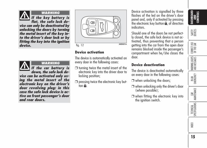
Device activation is signalled by threeflashes of the led on the driver’s doorpanel and, only if activated by pressingthe electronic key button Á, of directionindicators.
Should one of the doors be not perfect-ly closed, the safe lock device is not ac-tivated, thus preventing that a persongetting into the car from the open doorremains blocked inside the passenger’scompartment when he/she closes thedoor.
Device deactivation
The device is deactivated automaticallyon every door in the following cases:
❒ when unlocking the doors;
❒ when unlocking only the driver’s door(where possible);
❒ when fitting the electronic key intothe ignition switch.
Device activation
The device is automatically activated onevery door in the following cases:
❒ turning twice the metal insert of theelectronic key into the driver door tolocking position;
❒ pressing twice the electronic key but-ton Á.
A0E0021mfig. 12

16
SAFE
TYDE
VICES
WARN
ING LI
GHTS
AND M
ESSA
GES
IN AN
EM
ERGE
NCY
CAR
MAIN
TENA
NCE
TECH
NICA
LSP
ECIFI
CATIO
NSIN
DEX
DASH
BOAR
DAN
DCO
NTRO
LSCO
RREC
T USE
OF
THE C
ARThe main functions that can be activated with the electronic key or with the emergency metals insert are the following:
(*) On certain versions it is possible to set the option “Unlocking front door only” through the “Setup Menu” (see paragraph “Reconfigurable multifunctiondisplay” in this section). In this case pressing button Á and turning the metal insert of the electronic key counter-clockwise will unlock the driver’s dooronly. To unlock all the doors, press twice button Ëwithin 1 second or turn twice the metal insert of the electronic key counter-clockwise.
IMPORTANT Window and sunroof opening operations are a consequence of a door unlocking control. Window and sunroof closing operations are a con-sequence of a door locking control.
Electronickey
Emergencymetalinsert
Directionindicatorsflashing
Led ondriver’s door
Doors,tailgate
and fuel cap unlocking
Brief press onbutton Ë (*)
Electronic keyrotation
clockwise (*)
2 flashings
Deterrenceled off
Doors,tailgate
and fuel cap locking
Brief press onbutton Á
Electronic keyrotation
counter-clockwise
1 flashing
Turning on fixedfor 3 seconds,followed by
deterrence led flashing
Windowand sunroof
opening(where
provided)
Prolongedpressing
(over 2 seconds)on button Ë
Electronic key rotationfor over
2 seconds clockwise
2 flashings
Deterrence led off
Windowand sunroof
closing(where
provided)
Prolongedpressing
(over 2 seconds)on button Á
Electronic key rotationfor over
2 seconds counter-clockwise
1 flashing
Turning on fixedfor about
3 seconds, followed by
deterrence led flashing
Safe lock(where
provided)
Double pressing(within 1 second)
on button Á
Double electronickey rotation
within 1second
counter-clockwise
3 flashings
Doubleflashing,
followed bydeterrence led
flashing
Tailgate opening
Brief press on button`
–
2 flashings
–
17
SAFE
TYDE
VICES
WARN
ING LI
GHTS
AND M
ESSA
GES
IN AN
EM
ERGE
NCY
CAR
MAIN
TENA
NCE
TECH
NICA
LSP
ECIFI
CATIO
NSIN
DEX
DASH
BOAR
DAN
DCO
NTRO
LS
CORR
ECT U
SE
OF TH
E CAR
Depending on the markets, the trigger-ing of the alarm will activate the sirenand the hazard warning lights (for about26 seconds). The methods of operationand the number of cycles may vary de-pending on the versions/markets.
A maximum number of sound/sight cy-cles is however envisaged. Once thealarm cycle is over, the system will re-store its normal operation.
IMPORTANT Central door unlockingby the emergency electronic key will notdeactivate the alarm, therefore withalarm on the siren will activate whenopening one of the doors or the boot.To deactivate the siren see paragraph“How to deactivate the alarm”.
IMPORTANT The engine immobiliserfunction is guaranteed by the AlfaRomeo CODE system, which is auto-matically activated when the electronickey is removed from the ignition device.
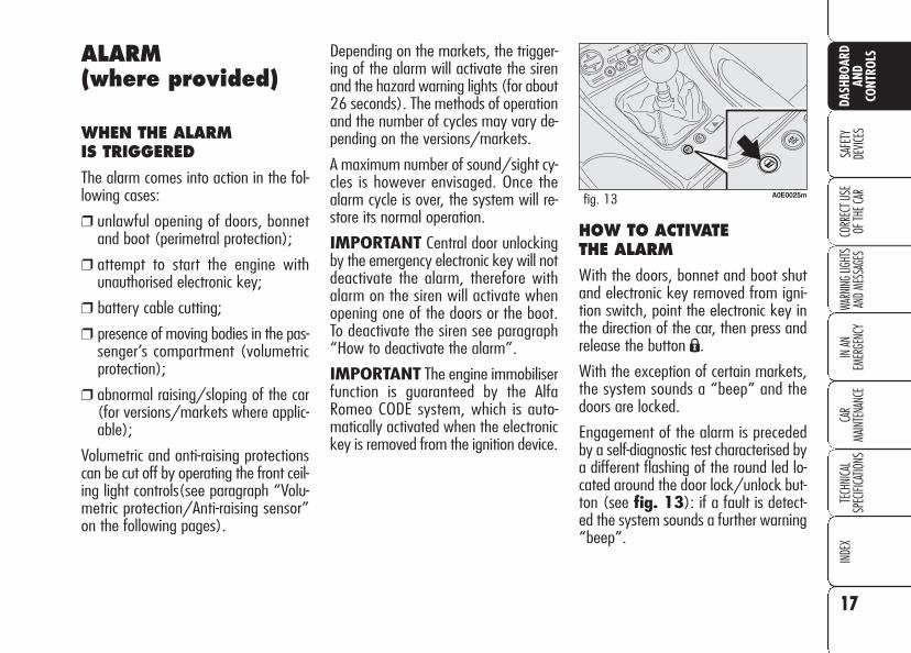
HOW TO ACTIVATE THE ALARM
With the doors, bonnet and boot shutand electronic key removed from igni-tion switch, point the electronic key inthe direction of the car, then press andrelease the button Á.
With the exception of certain markets,the system sounds a “beep” and thedoors are locked.
Engagement of the alarm is precededby a self-diagnostic test characterised bya different flashing of the round led lo-cated around the door lock/unlock but-ton (see fig. 13): if a fault is detect-ed the system sounds a further warning“beep”.
ALARM(where provided)
WHEN THE ALARM IS TRIGGERED
The alarm comes into action in the fol-lowing cases:
❒ unlawful opening of doors, bonnetand boot (perimetral protection);
❒ attempt to start the engine withunauthorised electronic key;
❒ battery cable cutting;
❒ presence of moving bodies in the pas-senger’s compartment (volumetricprotection);
❒ abnormal raising/sloping of the car(for versions/markets where applic-able);
Volumetric and anti-raising protectionscan be cut off by operating the front ceil-ing light controls(see paragraph “Volu-metric protection/Anti-raising sensor”on the following pages).
A0E0025mfig. 13

HOW TO DEACTIVATE THE ALARM
Press button Ë. The system will react asfollows (with the exception of certainmarkets):
❒ two brief flashes of the direction in-dicators;
❒ two brief “beeps”;
❒ door unlocking.
The alarm can be deactivated by fittingthe electronic key into the ignitionswitch.
IMPORTANT On certain versions anyattempt to break in detected by the sys-tem will be indicated by a warning mes-sage on the instrument panel displaywhen fitting the electronic key into theignition switch.
VOLUMETRIC PROTECTION/ANTI-RAISING SENSORS
To make sure that the protection sensorsare working properly, check that win-dows and sunroof (where provided) areshut.
This function can be cut out (for exam-ple if you leave animals on the car) bypressing button A-fig. 14 on the frontceiling light within 1 minute after in-strument panel turning off.
When this function is off the button ledwill turn on. Volumetric protection/anti-raising sensors cut out shall be repeatedat each instrument panel turning off.
Surveillance
When the system has been turned on,the led A-fig. 13 will flash to indicatethat the system is in the surveillancemode. The led will flash continuouslywhile the system is under surveillance.
IMPORTANT Operation of the alarmis adapted at the origin to the regula-tions of the different countries.
Self-diagnosis and monitoringof doors/bonnet/boot
If, after the alarm has been activated, asecond acoustic signal is heard, turn thesystem off by pressing button Ë, checkfor proper locking of doors, bonnet andboot, then turn the system on again bypressing button Á.
Otherwise if a door or bonnet/boot lidis not correctly closed it will not be con-trolled by the system. If the control sig-nal is repeated when the doors and bon-net/boot are closed properly this meansthat the self-diagnosis function has de-tected a system operating fault, in whichcase it is necessary to contact AlfaRomeo Authorized Services.
18
SAFE
TYDE
VICES
WARN
ING LI
GHTS
AND M
ESSA
GES
IN AN
EM
ERGE
NCY
CAR
MAIN
TENA
NCE
TECH
NICA
LSP
ECIFI
CATIO
NSIN
DEX
DASH
BOAR
DAN
DCO
NTRO
LSCO
RREC
T USE
OF
THE C
AR A0E0086mfig. 14

19
SAFE
TYDE
VICES
WARN
ING LI
GHTS
AND M
ESSA
GES
IN AN
EM
ERGE
NCY
CAR
MAIN
TENA
NCE
TECH
NICA
LSP
ECIFI
CATIO
NSIN
DEX
DASH
BOAR
DAN
DCO
NTRO
LS
CORR
ECT U
SE
OF TH
E CAR
IGNITION DEVICE
The ignition device is located on thedashboard and it consists of the follow-ing:
❒ electronic key reading device A-fig.15 (set near the steering wheel);
❒ button START/STOP (set under theelectronic key reading device).
IMPORTANT To prevent runningdown the battery do not leave the elec-tronic key into the ignition device whenthe engine is off.
HOW TO CUT OFF THE ALARM SYSTEM
To deactivate the alarm system com-pletely (for instance during prolongedinactivity of the car) simply lock the carby rotating the metal insert (providedinside the electronic key) into the dri-ver’s door lock.
MINISTERIALHOMOLOGATION
In keeping with the laws in force in eachcountry on the subject of radio fre-quency, for markets in which the trans-mitter needs to be marked the certifi-cation number is given on the compo-nent. For certain versions/markets, thecode may also be marked on the trans-mitter and/or on the receiver.
A0E0219mfig. 15
If the ignition device istampered with (for ex-
ample during an attemptedbreak-in) have it checked overby Alfa Romeo Authorized Ser-vices before travelling again.
WARNING
When leaving the caralways remove the
electronic key from the ignitiondevice to prevent any passen-ger in the car from inadver-tently activating the controls.Remember to engage thehandbrake and if the car is fac-ing uphill, first gear and if thecar is facing downhill, reverse.Never leave children unat-tended in the car.
WARNING

TURNING THE INSTRUMENTPANEL OFF
With engine off and clutch and brakepedals released, press button START/STOP or remove the electronic keyfrom the ignition device.
A few seconds after the instrument pan-el display will turn off gradually.
IMPORTANT Contact Alfa Romeo Au-thorized Services if the instrument pan-el fails to turn off.
TURNING THE INSTRUMENTPANEL ON
Proceed as follows:
❒ fit the electronic key into the ignitiondevice;
❒ if the electronic key is fitted yet, pressbutton START/STOP withoutpressing the clutch or brake pedal.
To safeguard the battery, when leavingthe car with the instrument panel on,electric and electronic devices will be de-activated after approx. 1 hour.
IMPORTANT Fit completely the elec-tronic key into the ignition device untilit locks into place.
IMPORTANT Contact Alfa Romeo Au-thorized Services if the instrument pan-el fails to turn on.
IMPORTANT If when fitting the elec-tronic key into the ignition device, thewarning light Y on the instrument pan-el comes on (on certain versions to-gether with a message on the display),check whether the electronic key is theproper one and then try to refit it intothe ignition device. If the problem per-sists contact Alfa Romeo Authorized Ser-vices.
20
SAFE
TYDE
VICES
WARN
ING LI
GHTS
AND M
ESSA
GES
IN AN
EM
ERGE
NCY
CAR
MAIN
TENA
NCE
TECH
NICA
LSP
ECIFI
CATIO
NSIN
DEX
DASH
BOAR
DAN
DCO
NTRO
LSCO
RREC
T USE
OF
THE C
AR A0E0028mfig. 16
ENGINE STARTING
See paragraph “Engine starting” in sec-tion “Correct use of the car”.
START/STOP BUTTONfig. 16
Button START/STOP, set on thedashboard, controls car electric systemsand engine starting/stopping.
Button START/STOP is fitted withknurled ring and led. When the led andthe instrument panel are on, the enginecan be started.

21
SAFE
TYDE
VICES
WARN
ING LI
GHTS
AND M
ESSA
GES
IN AN
EM
ERGE
NCY
CAR
MAIN
TENA
NCE
TECH
NICA
LSP
ECIFI
CATIO
NSIN
DEX
DASH
BOAR
DAN
DCO
NTRO
LS
CORR
ECT U
SE
OF TH
E CAR
ed) (or as an alternative, on certain ver-sions, a symbol and a message are dis-played). In this event contact AlfaRomeo Authorized Services.
IMPORTANT If after trying to turn onthe instrument panel and/or to start theengine, the instrument panel warninglight> (where provided) (or as an al-ternative, on certain versions the mes-sage "Vehicle protection system notavailable" is displayed), repeat the op-eration moving the steering wheel in or-der to release the steering lock. The dis-played warning message will not impairsteering lock operation.
INSTRUMENTS
REV. COUNTER
Rev counter shows engine rpm. The redzone at the scale bottom indicates thatthe engine is running at excessive rpmdangerous for mechanical components.Do not drive with the pointer in this area.
IMPORTANT The electronic injectioncontrol system gradually shuts off theflow of fuel when the engine is “over-revving” (rev counter pointer in the redarea) resulting in a gradual loss of en-gine power, in order to bring engine rpmbelow to the safety limit.
The rev counter may, when the engineis idling, indicate gradual or sudden in-crease of engine revs as the case maybe; such behaviour is normal and mustnot be interpreted as a faulty conditionas it occurs during normal operation, forinstance when climate control or electricfan are switched on. In particular, slowrevs variation helps keep the batterycharged.
STEERING COLUMN LOCK
Engaging
The steering column lock will engage5 seconds after removing the electron-ic key from the ignition device and if thefollowing conditions are present:❒ engine off;❒ instrument panel off with car at a
standstill;❒ electronic key removed from ignition
device.
Disengaging
The steering column lock will disengageafter fitting the electronic key into theignition device.
IMPORTANT Switching the engine offwhen the car is running will not engagethe steering column lock till next switch-ing off with car stopped. In this eventwarning light > (where provided) on theinstrument panel will come on (or as analternative, on certain versions, a sym-bol and a message are displayed).
IMPORTANT Steering column lockfailure is indicated by the instrumentpanel warning light > (where provid-
It is absolutely forbid-den to carry out what-
ever after-market operationinvolving steering system orsteering column modifications(e.g.: installation of anti-theftdevice) that could badly affectperformance and safety, causethe lapse of warranty and al-so result in non-compliance ofthe car with homologation re-quirements.
WARNING

22
SAFE
TYDE
VICES
WARN
ING LI
GHTS
AND M
ESSA
GES
IN AN
EM
ERGE
NCY
CAR
MAIN
TENA
NCE
TECH
NICA
LSP
ECIFI
CATIO
NSIN
DEX
DASH
BOAR
DAN
DCO
NTRO
LSCO
RREC
T USE
OF
THE C
AR
IMPORTANT The pointer can reachthe red area also for a sum of un-favourable conditions, i.e.: slow speed,uphill, fully laden or towing a trailer withhot outside temperature.
IMPORTANT Refuelling shall alwaysbe performed with engine off. Failing toobserve this precaution could cause thegauge to provide wrong indications.Should this occur, to restore proper in-dication just have next refuelling withthe engine off. Otherwise contact AlfaRomeo Authorized Services.
ENGINE COOLANTTEMPERATURE GAUGE fig. 18
This shows the temperature of the en-gine coolant fluid and begins workingwhen the fluid temperature exceeds ap-prox. 50°C.
The pointer should normally be towardsthe middle of the scale. If the pointerreaches the red sector, reduce your de-mand on the engine.
The turning on of the warning light u(on certain versions together with amessage on the display) indicates thatthe coolant fluid temperature is too high;in this case, stop the engine and contactAlfa Romeo Authorized Services .
IMPORTANT The pointer can reachthe red area also for a sum of un-favourable conditions, i.e.: slow speed,uphill, fully laden or towing a trailer withhot outside temperature.
FUEL GAUGE fig. 17
This shows the amount of fuel left in thefuel tank.
0 - tank empty.
1 - tank full (see the indications givenin paragraph “At the filling station").
The warning light on the fuel level gaugeturns on when about 10 litres fuel areleft in the tank. On certain versions. thedisplay will show a warning messagewhen the cruising range is less than 50km (or 31 mi).
If warning light K startsflashing when travellingcontact immediately Al-
fa Romeo Authorized Services.
A0E00177mfig. 17 A0E0178mfig. 18
23
SAFE
TYDE
VICES
WARN
ING LI
GHTS
AND M
ESSA
GES
IN AN
EM
ERGE
NCY
CAR
MAIN
TENA
NCE
TECH
NICA
LSP
ECIFI
CATIO
NSIN
DEX
DASH
BOAR
DAN
DCO
NTRO
LS
CORR
ECT U
SE
OF TH
E CAR
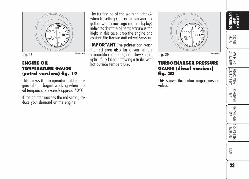
The turning on of the warning light `when travelling (on certain versions to-gether with a message on the display)indicates that the oil temperature is toohigh; in this case, stop the engine andcontact Alfa Romeo Authorized Services.
IMPORTANT The pointer can reachthe red area also for a sum of un-favourable conditions, i.e.: slow speed,uphill, fully laden or towing a trailer withhot outside temperature.ENGINE OIL
TEMPERATURE GAUGE(petrol versions) fig. 19
This shows the temperature of the en-gine oil and begins working when theoil temperature exceeds approx. 70°C.
If the pointer reaches the red sector, re-duce your demand on the engine.
A0E0179mfig. 19 A0E0180mfig. 20
TURBOCHARGER PRESSUREGAUGE (diesel versions)fig. 20
This shows the turbocharger pressurevalue.
24
SAFE
TYDE
VICES
WARN
ING LI
GHTS
AND M
ESSA
GES
IN AN
EM
ERGE
NCY
CAR
MAIN
TENA
NCE
TECH
NICA
LSP
ECIFI
CATIO
NSIN
DEX
DASH
BOAR
DAN
DCO
NTRO
LSCO
RREC
T USE
OF
THE C
ARAUTOMATIC INSTRUMENTPANEL LIGHT DIMMER
To give max. visibility and comfort un-der whatever driving conditions (e.g.:lights on in daylight, tunnels, etc…),the speedometer is fitted with a sensorfor adjusting automatically, after fittingthe electronic key into the ignition de-vice and pressing button START/STOP, the light intensity of the indi-cations given on the instrument paneldisplay, sound system display (whereprovided), climate control system dis-play, radionavigation system display(where provided), and instrument pan-el gauges (fuel level gauge, engine oiltemperature gauge (petrol versions) orsupercharger pressure gauge (diesel ver-sions) and engine coolant temperaturegauge).
MANUAL INSTRUMENTPANEL LIGHT DIMMER
With this function it is possible to adjuston 8 levels the light intensity of the indi-cations given on the instrument panel dis-play, sound system display (where pro-vided), climate control system display, ra-dionavigation system display (where pro-vided), and instrument panel gauges (fu-el level gauge, engine oil temperaturegauge (petrol versions) or superchargerpressure gauge (diesel versions) and en-gine coolant temperature gauge).
To increase light intensity press brieflybutton + on the left-hand stalk, to re-duce it press button –: the display willshow an indication and a figure corre-sponding to the current light intensitylevel. This screen will be displayed fora few seconds and then it will go off.
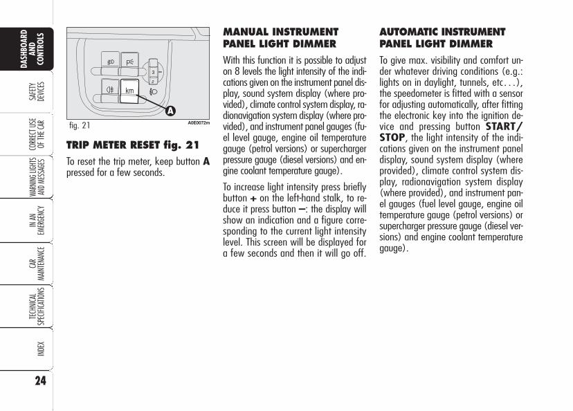
TRIP METER RESET fig. 21
To reset the trip meter, keep button Apressed for a few seconds.
A0E0072mfig. 21

25
SAFE
TYDE
VICES
WARN
ING LI
GHTS
AND M
ESSA
GES
IN AN
EM
ERGE
NCY
CAR
MAIN
TENA
NCE
TECH
NICA
LSP
ECIFI
CATIO
NSIN
DEX
DASH
BOAR
DAN
DCO
NTRO
LS
CORR
ECT U
SE
OF TH
E CAR
INFORMATION ABOUT CARCONDITIONS (at event)
❒ Scheduled servicing (symbol õD-fig. 22).
❒ Instrument panel light dimmer.
❒ Symbol of possible presence of ice onthe road (symbol √ E-fig. 22).
❒ Speed limit exceeded.
❒ Engine oil level.
MULTIFUNCTIONDISPLAY (where provided)
The “Multifunction display” shows allthe useful information necessary whendriving, more particularly:
INFORMATION ONSTANDARD SCREEN
❒ Clock A-fig. 22;
❒ External temperature B;
❒ Total km (or mi) or trip meter C(when total kilometres (or miles) areindicated the display will also showthe wording TOT).
Fitting the electronic key into the igni-tion device will display the total km (ormi), press button A-fig. 23 for trip me-ter (or mi).
A0E0060mfig. 22
A0E0072mfig. 23
To reset the trip meter (or mi), press forlong button A-fig. 23 during display-ing.

Speed limit (SPEED BEEP)
With this function it is possible to set thecar speed limit (km/h or mph) which,if exceeded, automatically sounds abuzzer and displays a specific message(see section “Warning lights and mes-sages”) to alert the driver. Once thewarning cycle is over the display willresume the standard screen. The warn-ing message will disappear only afterthe car speed slows 5 km/h (5 mph)below the set speed limit or after press-ing briefly the MENU button. This pro-cedure is carried out just once after ex-ceeding the speed limit and it can be re-peated only if the car speed slows atleast 5 km/h (5 mph) below the setspeed limit and then it increases untilexceeding the speed limit again.
26
SAFE
TYDE
VICES
WARN
ING LI
GHTS
AND M
ESSA
GES
IN AN
EM
ERGE
NCY
CAR
MAIN
TENA
NCE
TECH
NICA
LSP
ECIFI
CATIO
NSIN
DEX
DASH
BOAR
DAN
DCO
NTRO
LSCO
RREC
T USE
OF
THE C
AR A0E0074mfig. 24
“SETUP MENU”
There is also a “Setup Menu” enablingto perform the adjustments and/or set-tings described on the following pagesby pressing button MENU and +/–(see fig. 24). The Setup can be acti-vated by pressing briefly button MENU.
With the car stopped, thefollowing settings areenabled:
❒ Speed limit on/off and speed limitvalue.
❒ Clock.
❒ Failure/warning buzzer volume.
❒ “Distance” unit.
With the car running, only thefollowing setting is enabled:
❒ Speed limit on/off and speed limitvalue setting.
CONTROL BUTTONS (set on left stalk) fig. 24
MENU
Short push on button: to confirmthe required option and/or to go to nextscreen;
Long push on button: to confirm therequired option and to go back to stan-dard screen;
+/– to scroll up/down the “SetupMenu” options or to increase/decreasethe value displayed on the screen.
When the standard screen is displayedbuttons +/– activate instrument pan-el light dimming.

To set the speed limit, proceed as fol-lows:❒ press button MENU until selecting
SPEED BEEP: the display will showSPEED BEEP and setting condition(ON = speed limit on/ OFF= speedlimit off);
❒ press again button MENU: ON (orOFF) will flash;
❒ press buttons +/– to select ON orOFF;
❒ selecting ON will make the lastspeed limit set flashing on the dis-play;
❒ press buttons +/– to adjust the val-ue.
IMPORTANT The possible setting is be-tween 30 and 250 km/h (or between20 and 150 mph) depending on the unitset previously (see paragraph “Units” de-scribed later). Every press (pulse) of thebutton +/– increases or decreases thevalue by 5 units. Keeping the button +/–pressed obtains automatic fast increase ordecrease. When you are near the requiredsetting complete adjustment with singlepresses.
27
SAFE
TYDE
VICES
WARN
ING LI
GHTS
AND M
ESSA
GES
IN AN
EM
ERGE
NCY
CAR
MAIN
TENA
NCE
TECH
NICA
LSP
ECIFI
CATIO
NSIN
DEX
DASH
BOAR
DAN
DCO
NTRO
LS
CORR
ECT U
SE
OF TH
E CAR
Failure/warning buzzervolume (BUZZ)
With this function the volume of thebuzzer accompanying any failure/warn-ing indications can be adjusted accord-ing to 4 levels. The buzzer can be ad-justed and excluded.
Proceed as follows:
❒ press button MENU until selectingBUZZ: the display will show BUZZand a figure corresponding to thebuzzer volume level;
❒ press again button MENU: the fig-ure will flash;
❒ press buttons +/– to adjust thebuzzer volume.
To mute the buzzer set the volume lev-el to “0” using buttons +/–.
Clock (TIME REG)
This function enables to adjust the clock.
To adjust the clock proceed as follows:❒ press button MENU until selecting
TIME REG;❒ press again button MENU: TIME
and clock will flash;❒ press buttons +/– to adjust time.
Clock is always displayed in 24h mode(24 hours).

ENGINE OIL LEVELINDICATION
Fitting the electronic key into the igni-tion device, the display will show for afew seconds the engine oil level. At thisstage, to clear this indication and to goto next screen, press button MENU.
Low oil level will be indicated by a ded-icated warning message on the display.
IMPORTANT Check the proper en-gine oil level on the dipstick (see para-graph “Checking levels” in section “Carmaintenance”).
IMPORTANT Proper engine oil levelshall be checked with the car on levelground.
IMPORTANT To read the correct oillevel after fitting the electronic key, waitfor about 2 seconds before starting theengine.
IMPORTANT Engine oil level could in-crease after a long stop.
Scheduled servicing
IMPORTANT The Service schedule in-cludes car maintenance every 30,000km (or 18,000 mi); this is shown au-tomatically, with the electronic key in-to the ignition device starting from2,000 km (or 1,240 mi) from thisdeadline and it will be displayed in kmor miles according to the unit set. Whena scheduled service interval (“coupon”)is near to come, fitting the electronic keyinto the ignition device will display amessage followed by the number ofkm/mi to go before car servicing. Con-tact Alfa Romeo Authorized Services tocarry out any service operation provid-ed by the Service schedule or by the An-nual inspection plan, and to reset thedisplay.
28
SAFE
TYDE
VICES
WARN
ING LI
GHTS
AND M
ESSA
GES
IN AN
EM
ERGE
NCY
CAR
MAIN
TENA
NCE
TECH
NICA
LSP
ECIFI
CATIO
NSIN
DEX
CORR
ECT U
SE
OF TH
E CAR
DASH
BOAR
DAN
DCO
NTRO
LS Distance unit (UNIT)
With this function it is possible to set therequired distance unit (km or mi).
To set the distance unit, proceed as fol-lows:❒ press button MENU until selecting
UNIT: the display will show UNITand “km” or “mi”;
❒ press again button MENU: “km”(or “mi”) will flash;
❒ press buttons +/– to set the re-quired distance unit.

MESSAGES DISPLAYED AT STARTING
After the engine oil level, the display willshow for a few seconds a message in-dicating the procedure to follow to startthe engine (PRESS PEDAL ANDSTART: press brake or clutch pedal andthen press button START/STOP tostart the engine).
Once on, the NIGHT PAN functioncan be deactivated as follows:❒ by long press on button + (also with
external lights off);❒ removing the electronic key from the
ignition device.
When this function is off the displayshows “NIGHT PAN OFF”.
Messages “NIGHT PAN ON” or“NIGHT PAN OFF” stay on the dis-play for a few seconds, then they willgo off. To stop displaying before time,briefly press button MENU.
ILLUMINATION OF REVCOUNTER/INSTRUMENTS(NIGHT PAN)
This function enables to turn on/off(ON/OFF) the lights of the revcounter and instruments.
This function can be activated (only withelectronic key fitted into ignition device,external lights on, and speedometerbuilt-in sensor in poor outside light set-ting), by pressing for long button –.When this function is on, the display willshow “NIGHT PAN ON”.
29
SAFE
TYDE
VICES
WARN
ING LI
GHTS
AND M
ESSA
GES
IN AN
EM
ERGE
NCY
CAR
MAIN
TENA
NCE
TECH
NICA
LSP
ECIFI
CATIO
NSIN
DEX
CORR
ECT U
SE
OF TH
E CAR
DASH
BOAR
DAN
DCO
NTRO
LS
30
SAFE
TYDE
VICES
WARN
ING LI
GHTS
AND M
ESSA
GES
IN AN
EM
ERGE
NCY
CAR
MAIN
TENA
NCE
TECH
NICA
LSP
ECIFI
CATIO
NSIN
DEX
DASH
BOAR
DAN
DCO
NTRO
LSCO
RREC
T USE
OF
THE C
AR
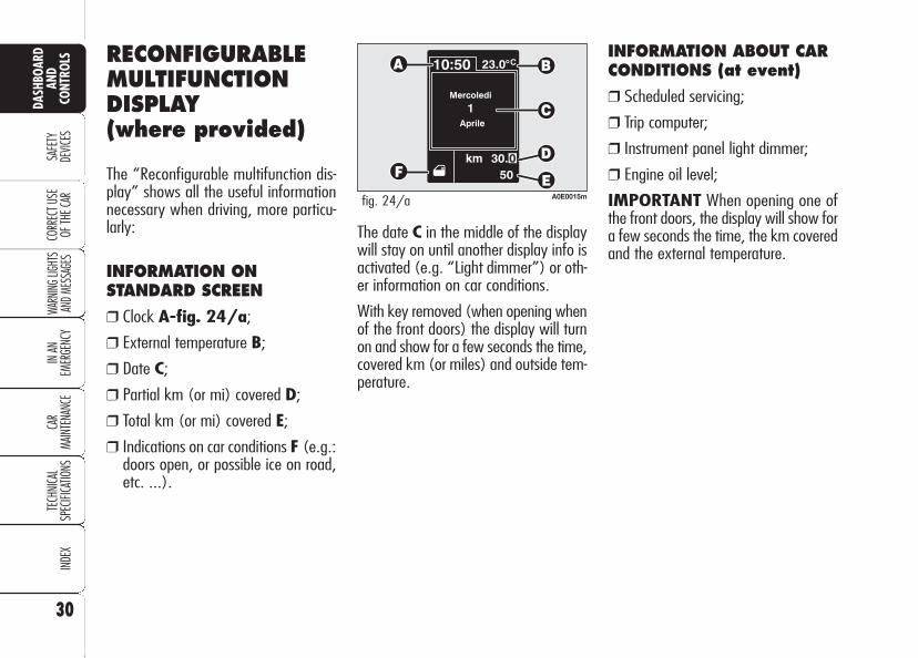
The date C in the middle of the displaywill stay on until another display info isactivated (e.g. “Light dimmer”) or oth-er information on car conditions.
With key removed (when opening whenof the front doors) the display will turnon and show for a few seconds the time,covered km (or miles) and outside tem-perature.
INFORMATION ABOUT CARCONDITIONS (at event)
❒ Scheduled servicing;
❒ Trip computer;
❒ Instrument panel light dimmer;
❒ Engine oil level;
IMPORTANT When opening one ofthe front doors, the display will show fora few seconds the time, the km coveredand the external temperature.
RECONFIGURABLEMULTIFUNCTIONDISPLAY (where provided)
The “Reconfigurable multifunction dis-play” shows all the useful informationnecessary when driving, more particu-larly:
INFORMATION ONSTANDARD SCREEN
❒ Clock A-fig. 24/a;
❒ External temperature B;
❒ Date C;
❒ Partial km (or mi) covered D;
❒ Total km (or mi) covered E;
❒ Indications on car conditions F (e.g.:doors open, or possible ice on road,etc. ...).
A0E0015mfig. 24/a

31
SAFE
TYDE
VICES
WARN
ING LI
GHTS
AND M
ESSA
GES
IN AN
EM
ERGE
NCY
CAR
MAIN
TENA
NCE
TECH
NICA
LSP
ECIFI
CATIO
NSIN
DEX
DASH
BOAR
DAN
DCO
NTRO
LS
CORR
ECT U
SE
OF TH
E CARA0E0074mfig. 25
“SETUP MENU”
There is also a “Setup Menu” enablingto perform the adjustments and/or set-tings described on the following pagesby pressing button MENU and +/–(see fig. 25).The Setup can be acti-vated by pressing briefly button MENU.
The menu comprises a series of func-tions arranged in a “circular fashion”fig. 26.
Selecting an option of the mainmenu without submenu:
❒ briefly press button MENU to selectthe main menu option to set;
❒ operate buttons + or – (by singlepress) to select the new setting;
❒ briefly press button MENU to storenew setting and go back to the pre-viously selected option of the mainmenu.
CONTROL BUTTONS
MENU
Short push on button: to confirmthe required option and/or to go to nextscreen;
Long push on button: to confirm therequired option and/or to go to previ-ous screen;
+/– to scroll up/down the “SetupMenu” options or to increase/decreasethe value displayed on the screen.
When the standard screen is displayedbuttons +/– activate instrument pan-el light dimming.

32
SAFE
TYDE
VICES
WARN
ING LI
GHTS
AND M
ESSA
GES
IN AN
EM
ERGE
NCY
CAR
MAIN
TENA
NCE
TECH
NICA
LSP
ECIFI
CATIO
NSIN
DEX
DASH
BOAR
DAN
DCO
NTRO
LSCO
RREC
T USE
OF
THE C
ARSelecting “Date” and “Clock”:
❒ briefly press button MENU to selectthe first value to change (e.g. hours/minutes or year/month/day);
❒ operate buttons + or – (by singlepress) to select the new setting;
❒ briefly press button MENU to storethe new setting and to go to the nextsetup menu option, if this is the lastone you will go back to the previouslyselected option of the main menu.
ENGINE OIL LEVELINDICATION
Fitting the electronic key into the igni-tion device, the display will show for afew seconds the engine oil level. At thisstage, to clear this indication and to goto next screen, press button MENU.
Low oil level will be indicated by a ded-icated warning message on the display.
IMPORTANT Check the proper en-gine oil level on the dipstick (see para-graph “Checking levels” in section “Carmaintenance”).
IMPORTANT Proper engine oil levelshall be checked with the car on levelground.
IMPORTANT To read the correct oillevel after fitting the electronic key, waitfor about 2 seconds before starting theengine.
IMPORTANT Engine oil level could in-crease after a long stop.
Selecting an option of the mainmenu with submenu:
❒ briefly press button MENU to displaythe first submenu option;
❒ operate buttons + or – (by singlepress) to scroll all submenu options;
❒ briefly press button MENU to selectthe displayed submenu option and toenter the corresponding setup menu;
❒ operate buttons + or – (by singlepress) to select the new setting of thissubmenu option;
❒ briefly press button MENU to storethe new setting and go back to thepreviously selected submenu option.

33
SAFE
TYDE
VICES
WARN
ING LI
GHTS
AND M
ESSA
GES
IN AN
EM
ERGE
NCY
CAR
MAIN
TENA
NCE
TECH
NICA
LSP
ECIFI
CATIO
NSIN
DEX
DASH
BOAR
DAN
DCO
NTRO
LS
CORR
ECT U
SE
OF TH
E CAR
Briefly press button MENU to access navigation from the standard screen. To surf the menu press buttons + or –. For safety rea-sons, when the car is running, it is possible to access only the reduced menu (for setting “Speed limit”). When the car is stationaryaccess to the whole menu is enabled. With the Radionavigation system it is only possible to adjust/set the following functions: “SpeedLimit”, “Light sensor sensitivity ” (where provided) and “S.B.R. buzzer reactivation” (where provided). The other functions are shownon the Radionavigation system display, that shall be use to adjust/set them as required.
fig. 26
BEEP VOL.
SERVICE
QUIT SETUP LIGHT SENS. RESET TRIP BCLOCK
MODE 12/24
DATE
AUDIO RPT.
INDEP. BOOT
UNLOCK FDADOOR LOCK UNITS
KEYS VOL.
LANGUAGE
SPEED LIMIT
A0E0218g
34
SAFE
TYDE
VICES
WARN
ING LI
GHTS
AND M
ESSA
GES
IN AN
EM
ERGE
NCY
CAR
MAIN
TENA
NCE
TECH
NICA
LSP
ECIFI
CATIO
NSIN
DEX
DASH
BOAR
DAN
DCO
NTRO
LSCO
RREC
T USE
OF
THE C
ARAutomatic headlight daylightsensor (where provided)(Light Sens.)
With this function it is possible to adjustthe light sensor sensitivity according to3 levels.
To adjust the volume proceed as follows:
❒ briefly press button MENU : the pre-viously set level will flash on the dis-play;
❒ press button + or – to select the re-quired volume;
❒ briefly press button MENU to goback to the menu screen or press thebutton for long to go back to the stan-dard screen.
Reset Trip B
This function enables to select Trip B re-set mode (Automatic or Manual).
For further information see paragraph“Trip computer”.
Speed limit
With this function it is possible to set thecar speed limit (km/h or mph) which,if exceeded, automatically sounds abuzzer and displays a special message(see section “Warning lights and mes-sages”) to alert the driver.
To set the speed limit, proceed as fol-lows:
❒ briefly press button MENU: the dis-play will show OFF;
❒ press button +: the display will showON;
❒ briefly press button MENU then, usebuttons +/– to set the requiredspeed (during setting the value willflash).
❒ briefly press button MENU to goback to the menu screen or press thebutton for long to go back to the stan-dard screen.
IMPORTANT The possible setting isbetween 30 and 250 km/h (or be-tween 20 and 150 mph) depending onthe unit set previously (see paragraph“Units” described later). Every press(pulse) of the button +/– increases ordecreases the value by 5 units. Keepingthe button +/– pressed obtains auto-matic fast increase or decrease. Whenyou are near the required setting com-plete adjustment with single presses.
To abort the setting:
❒ briefly press button MENU: the dis-play will show ON;
❒ press button –: the display will showOFF;
❒ briefly press button MENU to goback to the menu screen or press thebutton for long to go back to the stan-dard screen.

35
SAFE
TYDE
VICES
WARN
ING LI
GHTS
AND M
ESSA
GES
IN AN
EM
ERGE
NCY
CAR
MAIN
TENA
NCE
TECH
NICA
LSP
ECIFI
CATIO
NSIN
DEX
DASH
BOAR
DAN
DCO
NTRO
LS
CORR
ECT U
SE
OF TH
E CAR
IMPORTANT Every press (pulse) onthe button +/– increases/decreases byone unit. Keeping button +/– pressedobtains fast increase/decrease. Whenyou are near the required setting com-plete adjustment with single presses.
❒ briefly press button MENU to goback to the menu screen or press thebutton for long to go back to the stan-dard screen.
Setting the clock (Clock)
This function enables to set the clock.
Proceed as follows:
❒ briefly press button MENU: “hours”will show on the display;
❒ press button + or – to select the re-quired volume;
❒ briefly press button MENU: “min-utes” will flash on the display;
❒ press button + or – to adjust;
Clock mode (Mode 12/24)
This function is used to set the clock inthe 12h or 24h mode.
To adjust proceed as follows:
❒ briefly press button MENU: 12h or24h (according to previous setting)will show on the display;
❒ press button + or – to select the re-quired language;
❒ briefly press button MENU to goback to the menu screen or press thebutton for long to go back to the stan-dard screen.
36
SAFE
TYDE
VICES
WARN
ING LI
GHTS
AND M
ESSA
GES
IN AN
EM
ERGE
NCY
CAR
MAIN
TENA
NCE
TECH
NICA
LSP
ECIFI
CATIO
NSIN
DEX
DASH
BOAR
DAN
DCO
NTRO
LSCO
RREC
T USE
OF
THE C
ARSetting the date (Date)
This function enables to update the date(year - month - day).
Proceed as follows:
❒ briefly press button MENU: “year”will flash on the display;
❒ press button + or – to select the re-quired volume;
❒ briefly press button MENU: “month”will flash on the display;
❒ press button + or – to select the re-quired volume;
❒ briefly press button MENU: “day”will flash on the display;
❒ press button + or – to adjust;
IMPORTANT Every press (pulse) onthe button +/– increases/decreases byone unit. Keeping button +/– pressedobtains fast increase/decrease. Whenyou are near the required setting com-plete adjustment with single presses.
❒ briefly press button MENU to goback to the menu screen or press thebutton for long to go back to the stan-dard screen.
Audio Info Repetition(Audio Rpt.) (where provided)
This function enables to display soundsystem information.
❒ Radio: selected radio station fre-quency or RDS message, automatictuning activation or AutoSTore;
❒ Audio CD, MP3 CD: selected tracknumber;
❒ CD Changer: CD number and tracknumber;
To activate/deactivate (ON/OFF) in-fo displaying proceed as follows:
❒ briefly press button MENU: the dis-play will show ON or OFF (accord-ing to previous setting);
❒ press button + or – to select the re-quired source;
❒ briefly press button MENU to goback to the menu screen or press thebutton for long to go back to the stan-dard screen.
According to the audio source selected,below the time will be displayed thesymbol of the current source.

37
SAFE
TYDE
VICES
WARN
ING LI
GHTS
AND M
ESSA
GES
IN AN
EM
ERGE
NCY
CAR
MAIN
TENA
NCE
TECH
NICA
LSP
ECIFI
CATIO
NSIN
DEX
DASH
BOAR
DAN
DCO
NTRO
LS
CORR
ECT U
SE
OF TH
E CAR
Driver’s door unlocking(Unlock Fda)
With this function it is possible to unlockonly the driver’s door by pressing theelectronic key button Ë.
With this function active (ON), it ishowever possible to unlock the otherdoors by pressing the door unlock but-ton on central console.
To activate/deactivate (ON/OFF) thisfunction proceed as follows:
❒ briefly press button MENU: ON orOFF (according to previous setting)will flash on the display;
❒ press button + or – to select the re-quired language;
❒ briefly press button MENU to goback to the menu screen or press thebutton for long to go back to the stan-dard screen.
Automatic central door locking(Door lock)
When activated (ON), this functionlocks automatically the doors when thecar speed exceeds 20 km/h.
To activate/deactivate (ON/OFF) thisfunction proceed as follows:
❒ briefly press button MENU: ON orOFF (according to previous setting)will flash on the display;
❒ press button + or – to select the re-quired language;
❒ briefly press button MENU to goback to the menu screen or press thebutton for long to go back to the stan-dard screen.
Function activation is indicated by thecircular led around the button q.
Independent boot unlocking(Indep. Boot)
With this function it is possible to unlockthe boot independently from doors.
When the function is enabled, the trunkopens by pressing ` on the elec-tronic key, or by acting on the lever lo-cated under the left back seat (refer to“Boot” paragraph in this chapter) in-hibiting the key that opens the trunk lo-cated on the front roof light.
To activate independent boot function(ON) or deactivate it (OFF), proceedas follows:
❒ briefly press button MENU : ON orOFF (according to previous setting)will flash on the display;
❒ press button + or – to select the re-quired language;
❒ briefly press button MENU to goback to the menu screen or press thebutton for long to go back to the stan-dard screen.

Consumption
If the distance unit set is km (see pre-vious paragraph) the display will enableto set the fuel consumption unit (l/100km, km/l or mpg).
If the distance unit set is “mi” (see pre-vious paragraph) fuel consumption willbe displayed “mpg”.
In this case the option “Cons.Unit” of the“Setup Menu” can be selected but it islocked on “mpg”.
To set the required unit proceed as fol-lows:
❒ briefly press button MENU: “km/l”or “l/100 km” (according to previ-ous setting) will show on the display;
❒ press button + or – to select the re-quired language;
❒ briefly press button MENU to goback to the menu screen or press thebutton for long to go back to the stan-dard screen.
Temperature
This function enables to set the tem-perature unit (°C or °F).
To set the required unit proceed as fol-lows:
❒ briefly press button MENU: °C or °F(according to previous setting) willshow on the display;
❒ press button + or – to select the re-quired language;
❒ briefly press button MENU to goback to the menu screen or press thebutton for long to go back to the stan-dard screen.
Units
With this function it is possible to set theunits for distance covered (km or mi),fuel consumption (l/100 km, km/l ormpg) and temperature (°C or °F).
Distance
To set the required unit proceed as fol-lows:
❒ briefly press button MENU: “km” or“mi” (according to previous setting)will show on the display;
❒ press button + or – to select the re-quired language;
❒ briefly press button MENU to goback to the menu screen or press thebutton for long to go back to the stan-dard screen.
38
SAFE
TYDE
VICES
WARN
ING LI
GHTS
AND M
ESSA
GES
IN AN
EM
ERGE
NCY
CAR
MAIN
TENA
NCE
TECH
NICA
LSP
ECIFI
CATIO
NSIN
DEX
DASH
BOAR
DAN
DCO
NTRO
LSCO
RREC
T USE
OF
THE C
AR

39
SAFE
TYDE
VICES
WARN
ING LI
GHTS
AND M
ESSA
GES
IN AN
EM
ERGE
NCY
CAR
MAIN
TENA
NCE
TECH
NICA
LSP
ECIFI
CATIO
NSIN
DEX
DASH
BOAR
DAN
DCO
NTRO
LS
CORR
ECT U
SE
OF TH
E CAR
Selecting the language(Language)
Display messages can be shown in thefollowing languages: Italian, English,German, Portuguese, Spanish, French,Dutch and Brazilian.
To set the required language proceed asfollows:
❒ briefly press button MENU , the pre-viously set “language” will show onthe display;
❒ press button + or – to select the re-quired language;
❒ briefly press button MENU to goback to the menu screen or press thebutton for long to go back to the stan-dard screen.
Adjusting the button volume(Keys Vol.)
With this function the volume of theroger-beep accompanying the activationof certain buttons can be adjusted ac-cording to 8 levels.
To adjust the volume proceed as follows:
❒ briefly press button MENU, the pre-viously set “level” will show on thedisplay;
❒ press button + or – to select the re-quired volume;
❒ briefly press button MENU to goback to the menu screen or press thebutton for long to go back to the stan-dard screen.
Adjusting the failure/warningbuzzer volume (Beep Vol.)
With this function the volume of thebuzzer accompanying any failure/warn-ing indication can be adjusted accordingto 8 levels.
To adjust the volume proceed as follows:
❒ briefly press button MENU, the pre-viously set “level” will show on thedisplay;
❒ press button + or – to select the re-quired volume;
❒ briefly press button MENU to goback to the menu screen or press thebutton for long to go back to the stan-dard screen.

Reactivating the S.B.R.(Seat Belt Reminder) buzzer(Beep Seatb.) (where provided)
This function is displayed only after thesystem has been deactivated by AlfaRomeo Authorized Services.
Exit Menu (Quit setup)
Selecting this option will bring back tostandard screen.
ILLUMINATION OF REVCOUNTER/INSTRUMENTS(NIGHT PANEL)
This function enables to turn on/off(ON/OFF) the lights of the rev counterand instruments. This function can be ac-tivated (only with electronic key fitted in-to ignition device, external lights on, andspeedometer built-in sensor in poor out-side light setting), by pressing for long but-ton –. When this function is on, the dis-play will show a warning message. Onceon, the NIGHT PANEL function can bedeactivated as follows:❒ by long press on button + (also with
external lights off);❒ removing the electronic key from the
ignition device.
When function is off the display will showa warning message.
Messages stay on the display for a fewseconds, then they will go off. To stopdisplaying before time, briefly press but-ton MENU.
Scheduled Servicing (Service)Through this function it is possible to dis-play information connected to proper carservicing.Proceed as follows:❒ briefly press button MENU : service
in km or mi, according to previoussetting, will be displayed (see para-graph “Units”);
❒ briefly press button MENU to goback to the menu screen or press thebutton for long to go back to the stan-dard screen.
IMPORTANT The Service schedule in-cludes car maintenance every 30,000 km(or 18,000 mi); this is shown automat-ically, with the electronic key into the ig-nition device starting from 2,000 km (or1,240 mi) from this deadline and it willbe displayed in km or miles according tothe unit set. When a scheduled service in-terval (“coupon”) is near to come, fittingthe electronic key into the ignition devicewill display a message followed by thenumber of km/mi to go before car ser-vicing. Contact Alfa Romeo Authorized Ser-vices to carry out any service operationprovided by the Service schedule or by theAnnual inspection plan, and to reset thedisplay.
40
SAFE
TYDE
VICES
WARN
ING LI
GHTS
AND M
ESSA
GES
IN AN
EM
ERGE
NCY
CAR
MAIN
TENA
NCE
TECH
NICA
LSP
ECIFI
CATIO
NSIN
DEX
DASH
BOAR
DAN
DCO
NTRO
LSCO
RREC
T USE
OF
THE C
AR
41
SAFE
TYDE
VICES
WARN
ING LI
GHTS
AND M
ESSA
GES
IN AN
EM
ERGE
NCY
CAR
MAIN
TENA
NCE
TECH
NICA
LSP
ECIFI
CATIO
NSIN
DEX
DASH
BOAR
DAN
DCO
NTRO
LS
CORR
ECT U
SE
OF TH
E CAR
Reset TRIP BEnd of partial mission
Start of new partial mission End of partial missionStart of new
partial mission Reset TRIP BEnd of partial mission
Start of new partial mission
Reset Trip AEnd of complete mission
Start of new mission
Reset Trip AEnd of complete mission
Start of new mission
End of partial missionStart of new
partial mission
Reset TRIP B
Reset TRIP B
TRIP B
TRIP B
TRIP B
Trip A
˙
˙
˙
˙ ˙
˙
˙ ˙
fig. 27
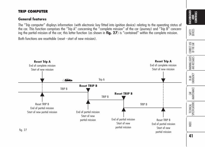
TRIP COMPUTER
General features
The “Trip computer” displays information (with electronic key fitted into ignition device) relating to the operating status ofthe car. This function comprises the “Trip A” concerning the “complete mission” of the car (journey) and “Trip B” concern-ing the partial mission of the car; this latter function (as shown in fig. 27) is “contained” within the complete mission.
Both functions are resettable (reset - start of new mission).

42
SAFE
TYDE
VICES
WARN
ING LI
GHTS
AND M
ESSA
GES
IN AN
EM
ERGE
NCY
CAR
MAIN
TENA
NCE
TECH
NICA
LSP
ECIFI
CATIO
NSIN
DEX
DASH
BOAR
DAN
DCO
NTRO
LSCO
RREC
T USE
OF
THE C
ARValues displayed
Average consumption
This value shows the average con-sumption from the start of the new mis-sion.
Current consumption
This value shows instant fuel consump-tion (this value is updated second bysecond). If parking the car with engineon, the display will show “- - - -”.
Average speed
This value shows the car average speedas a function of the overall time elapsedsince the start of the new mission.
Travel time
This value shows the time elapsed sincethe start of the new mission (drivingtime).
Range
This value shows the distance in km (ormi) that the car can still cover beforeneeding fuel, assuming that driving con-ditions are kept unvaried.
The display will show “- - - -“ in the fol-lowing cases:
❒ value lower than 50 km (30mi);
❒ car left parked with engine runningfor long.
Travel Distance
This value shows the distance coveredfrom the start of the new mission.
Each time the battery is connected andeach time a new mission is started (re-set), the display will show “0.0”.
IMPORTANT Lacking information,Trip computer values are displayed with“- - - -”. When normal operating condi-tion is reset, calculation of different unitswill restart regularly. Values displayedbefore the failure will not be reset.
The “Trip A” displays the figures relatingto:
❒ Average consumption
❒ Current consumption
❒ Average speed
❒ Travel time
❒ Range
❒ Travel Distance
“Trip B” displays information concern-ing:
❒ Travel Distance B
❒ Average consumption B
❒ Average speed B
❒ Travel time B.

43
SAFE
TYDE
VICES
WARN
ING LI
GHTS
AND M
ESSA
GES
IN AN
EM
ERGE
NCY
CAR
MAIN
TENA
NCE
TECH
NICA
LSP
ECIFI
CATIO
NSIN
DEX
DASH
BOAR
DAN
DCO
NTRO
LS
CORR
ECT U
SE
OF TH
E CAR
Button TRIP shall also be used to resetthe “Trip A” and “Trip B” functions tostart a new mission:
❒ short push: to display the differentvalues;
❒ long push: to reset and then starta new mission.
To scroll the Trip Computer options,briefly press buttons - and..
IMPORTANT “Trip A” reset will alsoreset the “Trip B” function, whereas“Trip B” reset will only reset the infor-mation associated with this function.
New mission (reset)
Reset can be:
❒ “manual” reset is performed by thedriver by pressing button TRIP;
❒ “automatic” reset is performed whenthe trip distance reaches 9999.9 km(or mi), when travel time reaches99.59 (99 hours and 59 minutes)or after disconnecting and then re-connecting the battery.
TRIP BUTTON
Button TRIP fig. 28, set on the rightsteering column stalk shall be used (withelectronic key into ignition device) to en-ter the “Trip A” and “Trip B” function.To scroll the values of each option usebuttons set aside the stalk.
A0E0076mfig. 28
Every Trip computer screen displays twooptions of the active Trip (Trip A or TripB); one option is displayed at the top ofthe screen, the other one at the bottom(see fig. 29).
In the same screen it is not possible tohave displayed at the same time thesame option at the top and at the bot-tom of the screen.
A0E0052mfig. 29
Reset Trip B
As concerns the Trip B values, it is pos-sible to select through the “SetupMenu” the reset mode (Manual or Au-tomatic) (see paragraph “Setup Menu”on previous pages):
❒ manual reset: press and keep pressedbutton TRIP for over 2 seconds.
❒ automatic reset: it takes place eachtime the electronic key is fitted intothe ignition device.
At Trip B reset a warning message willbe displayed.
IMPORTANT Trip B reset will not re-set “Range” and “Current Consump-tion”.
44
SAFE
TYDE
VICES
WARN
ING LI
GHTS
AND M
ESSA
GES
IN AN
EM
ERGE
NCY
CAR
MAIN
TENA
NCE
TECH
NICA
LSP
ECIFI
CATIO
NSIN
DEX
DASH
BOAR
DAN
DCO
NTRO
LSCO
RREC
T USE
OF
THE C
ARBriefly press button TRIP to select thetwo Trip computer modes; use button- to scroll the options at the top of thedisplay, use button .. to scroll the op-tions at the bottom of the display.
Press briefly button TRIP to go fromTrip A to Trip B.
Start of journey procedure(reset)
Trip A and Trip B reset are independent.
Reset Trip A
With electronic key into ignition device,to reset the “Trip A” press and keeppressed button TRIP for over 2 sec-onds.
IMPORTANT Reset can be automat-ic only in the following cases:
❒ when the “Travel Distance” reaches9999.9 km or the “Travel Time”reaches 99.59 (99 hours and 59minutes);
❒ after disconnecting/reconnecting thebattery.
At Trip A reset a warning message willbe displayed.
IMPORTANT Trip A reset will not re-set “Range” and “Current Consump-tion”.

On versions fitted with T.P.M.S. system(Tyre pressure Monitoring System) (seeparagraph “T.P.M.S. system” in this sec-tion), after Trip A and Trip B info, thescreen with tyre pressure condition is dis-played (see fig. 30).
NOTE When starting the engine andfor a short time, if you have recalled theplan view by pressing the TRIP button,dashes will be displayed instead of"OK/NO". This is normal since the sys-tem is checking tyre inflation pressurevalues.
45
SAFE
TYDE
VICES
WARN
ING LI
GHTS
AND M
ESSA
GES
IN AN
EM
ERGE
NCY
CAR
MAIN
TENA
NCE
TECH
NICA
LSP
ECIFI
CATIO
NSIN
DEX
CORR
ECT U
SE
OF TH
E CAR
DASH
BOAR
DAN
DCO
NTRO
LS
A0E0053mfig. 30
SEATS
MANUALLY ADJUSTABLEFRONT SEATS fig. 31
Only make adjustmentswhen the car is sta-
tionary.
WARNING
Upholstery of your carhas been designed towithstand wear deriv-
ing from common use of the car.You are however recommendedto avoid strong and/or contin-uous scratching with clothingaccessories such as metallicbuckles, studs, Velcro fasten-ings and the like, since theseitems cause circumscribed stressof the cover fabric that couldlead to yarn breaking, and dam-age the cover as a consequence.
Moving the seat backwardsor forwards
Lift the lever A (on the inner side of theseat) and push the seat forwards orbackwards: in the driving position thearms should rest on the rim of the steer-ing wheel.
A0E0020mfig. 31

46
SAFE
TYDE
VICES
WARN
ING
LIGHT
S AN
D ME
SSAG
ESIN
AN
EMER
GENC
YCA
RMA
INTE
NANC
ETE
CHNI
CAL
SPEC
IFICA
TIONS
INDE
XCO
RREC
T USE
OF
THE C
AR
DASH
BOAR
DAN
DCO
NTRO
LS
Height adjustment (where provided)
Move repeatedly lever B upwards ordownwards to achieve the requiredheight.
IMPORTANT Adjustment must be car-ried out only seated at the driver’s seat.
Back rest angle adjustment
Turn the knob C until obtaining the re-quired position.
Lumbar adjustment(where provided)
Turn the knob D until obtaining the re-quired position.
Once you have re-leased the lever, check
that the seat is firmly lockedin the runners by trying tomove it back and forth. Failureto lock the seat in place couldresult in the seat moving sud-denly and the driver losingcontrol of the car.
WARNING
ELECTRICALLY ADJUSTABLEFRONT SEATS fig. 33
Back rest angle adjustment(where provided)
Use lever E. Pulling the lever upwardsthe seat will bend back by one position.Pushing the lever downwards the seatwill bend forward.
Seat warming (where provided)
With electronic key fitted into ignitiondevice, turn ring nut A-fig. 32 to turnthis function on/off.
Seat warming can be adjusted to 3 dif-ferent levels (0 = seat warming off).
A0E0024mfig. 32
Only make adjustmentswhen the car is station-
ary.
WARNING
A0E0189mfig. 33

47
SAFE
TYDE
VICES
WARN
ING
LIGHT
S AN
D ME
SSAG
ES
IN AN
EM
ERGE
NCY
CAR
MAIN
TENA
NCE
TECH
NICA
LSP
ECIFI
CATIO
NSIN
DEX
CORR
ECT U
SE
OF TH
E CAR
DASH
BOAR
DAN
DCO
NTRO
LSSeat controls are thefollowing:
Multifunction control A:
– front seat height adjustment;
– rear seat height adjustment;
– vertical seat movement;
– longitudinal seat movement;
B: Back rest angle adjustment;
C: Driver’s seat positions store buttons;
D: Lombar adjustment.
IMPORTANT Seat can only be ad-justed when the electronic key is fittedinto the ignition device and for about 1minute from removing it or after press-ing button START/STOP. After open-ing the door the seat can be adjusted forabout 3 minutes or until closing thedoor.
Storing driver’s seat/doormirror positions
Buttons C allows to store and recall threedifferent driver’s seat and door mirror po-sitions. Storing and recalling are only pos-sible with electronic key fitted into igni-tion device.
Stored position can only be recalled forabout 3 minutes after opening the doorsand for about 1 minute after removingthe electronic key from the ignition de-vice.
To store the required seat position, ad-just it as required then press the buttoncorresponding to position to store for afew seconds.
To recall the stored position, press brieflythe corresponding button.
Storing a new position will automaticallyclear the one stored previously using thesame button.
FRONT SEATS SPORTS (where provided) fig. 33/a
Certain versions are fitted with manu-ally or electrically adjustable front seatswith sports configuration.
To adjust these seats see the indicationscontained in previous paragraphs.
A0E0421mfig. 33/a

48
SAFE
TYDE
VICES
WARN
ING
LIGHT
S AN
D ME
SSAG
ESIN
AN
EMER
GENC
YCA
RMA
INTE
NANC
ETE
CHNI
CAL
SPEC
IFICA
TIONS
INDE
XCO
RREC
T USE
OF
THE C
AR
DASH
BOAR
DAN
DCO
NTRO
LS
REAR HEAD RESTRAINTS
Rear seats are fitted with two head re-straints.
Certain versions are fitted with height-ad-justable head restraint also for the centralseat (see previous paragraph for heightadjustment).
If required, head restraints can be re-moved as follows:
❒ raise head restraints to max. height;
❒ press buttons A-fig. 35 (set asidethe two head restraint supports) thenremove the head restraints by pullingthem upwards.
A0E0033mfig. 34
Remember that thehead restraints should
be adjusted to support theback of your head and notyour neck. Only in this positiondo they exert their protectiveaction. To optimise head re-straint protective action, adjustthe seat back upright and keepyour head as close as possibleto the head restraint.
WARNING
A0E0137mfig. 35
HEAD RESTRAINTS
FRONT HEAD RESTRAINTSfig. 34
Head restraints are adjustable in heightand, on certain versions, also in angleand they lock automatically in the re-quired position.
To adjust height proceed as follows:
❒ to raise: raise the head restraint un-til hearing the locking click.
❒ to lower: press button A and lowerthe head restraint.
To adjust head restraint angle (whereprovided) turn it by hand.
If required, head restraints can be re-moved as follows:
❒ raise head restraints to max. height;
❒ press buttons A-fig. 34 (set asidethe two head restraint supports) thenremove the head restraints by pullingthem upwards.
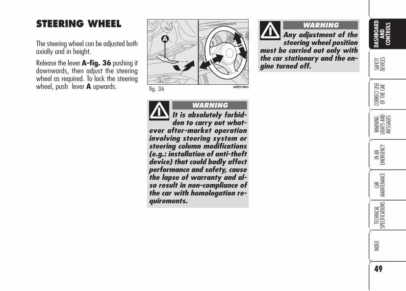
49
SAFE
TYDE
VICES
WARN
ING
LIGHT
S AN
D ME
SSAG
ES
IN AN
EM
ERGE
NCY
CAR
MAIN
TENA
NCE
TECH
NICA
LSP
ECIFI
CATIO
NSIN
DEX
CORR
ECT U
SE
OF TH
E CAR
DASH
BOAR
DAN
DCO
NTRO
LSSTEERING WHEEL
The steering wheel can be adjusted bothaxially and in height.
Release the lever A-fig. 36 pushing itdownwards, then adjust the steeringwheel as required. To lock the steeringwheel, push lever A upwards.
It is absolutely forbid-den to carry out what-
ever after-market operationinvolving steering system orsteering column modifications(e.g.: installation of anti-theftdevice) that could badly affectperformance and safety, causethe lapse of warranty and al-so result in non-compliance ofthe car with homologation re-quirements.
WARNING
A0E0136mfig. 36
Any adjustment of thesteering wheel position
must be carried out only withthe car stationary and the en-gine turned off.
WARNING

50
SAFE
TYDE
VICES
WARN
ING
LIGHT
S AN
D ME
SSAG
ESIN
AN
EMER
GENC
YCA
RMA
INTE
NANC
ETE
CHNI
CAL
SPEC
IFICA
TIONS
INDE
XCO
RREC
T USE
OF
THE C
AR
DASH
BOAR
DAN
DCO
NTRO
LS
Certain versions are fitted with electro-chromic mirror fig. 38. The electro-chromic function is turned on/off bypressing button ON/OFF in the low-er section of the mirror. When engagingreverse, the mirror will always set todaylight colouring.
REARVIEWMIRRORS
DRIVING MIRROR
The mirror is fitted with a safety devicethat causes it to be released in the eventof a violent crash. A0E0135mfig. 37 A0E0032mfig. 38
Using lever A-fig. 37 the mirror canbe adjusted to two different positions:normal or antiglare.

51
SAFE
TYDE
VICES
WARN
ING
LIGHT
S AN
D ME
SSAG
ES
IN AN
EM
ERGE
NCY
CAR
MAIN
TENA
NCE
TECH
NICA
LSP
ECIFI
CATIO
NSIN
DEX
CORR
ECT U
SE
OF TH
E CAR
DASH
BOAR
DAN
DCO
NTRO
LSElectrically folding of themirror (only versions with 4power windows)(optional for versions/markets where applicable)
When required (for example when themirror causes difficulty in narrow spaces)it is possible to fold the mirrors by press-ing button C-fig. 39.
To bring the mirrors back to driving po-sition press again button C-fig. 39.
A0E0081mfig. 40
Manually folding of the mirror
When required (for example when themirror causes difficulty in narrow spaces)it is possible to fold the mirror moving itfrom position A-fig. 40 to position B.
DOOR MIRRORS
Door mirror can only be adjusted andfolded when the electronic key is fittedinto the ignition device.
Adjusting the mirror
Use device A-fig. 39 to select the re-quired mirror:
❒ turn selector A to 1 to select the leftdoor mirror;
❒ turn selector A to 2 to select the rightdoor mirror.
To adjust the mirror selected press but-ton B in the four directions shown bythe arrows.
IMPORTANT After adjusting the mir-ror, turn selector A to 0 to prevent ac-cidental movements.
A0E0036mfig. 39
As the driver’s door mir-ror is curved, it mayslightly alter the per-
ception of distance.
When driving the mir-rors shall always be in
open position.
WARNING

52
SAFE
TYDE
VICES
WARN
ING
LIGHT
S AN
D ME
SSAG
ESIN
AN
EMER
GENC
YCA
RMA
INTE
NANC
ETE
CHNI
CAL
SPEC
IFICA
TIONS
INDE
XCO
RREC
T USE
OF
THE C
AR
DASH
BOAR
DAN
DCO
NTRO
LS Storing the “parking”position of the door mirror on the passenger side
On versions equipped with electric seats,when engaging reverse for parking toimprove visibility the driver can adjust(and store) the passenger's door mirrorto a position different than that usedcommonly. To store mirror position pro-ceed as follows:
❒ To perform storing, proceed as fol-lows: engage reverse with carstopped and electronic key fitted in-to the ignition device;
❒ move device A-fig. 39 to position2 (passenger door mirror selection);
❒ adjust the passenger door mirror toobtain the best position for parkingmanoeuvres;
❒ keep one of the buttons C-fig. 33pressed for at least 3 seconds (seeparagraph “Seats” in this section).
Together with the passenger door mir-ror “parking” position, also the driverseat position and the driver door mirrorwill be stored. The sound of a buzzerwill confirm that the mirror position hasbeen stored.
Recalling the passenger doormirror “parking” position
Proceed as follows: fit the electronic keyinto the ignition device, engage reverse,move device A-fig. 39 to position 2(passenger door mirror selection).
The mirror will set automatically to thepreviously stored position.
If no parking position has been stored,when engaging reverse the passengerdoor mirror will slightly lower to favourthe parking manoeuvre.
The passenger door mirror will return au-tomatically to its original position about10 seconds after disengaging reverse,immediately after exceeding 10 km/hwith forward gear or when moving de-vice A-fig. 39 to 0.
Automatic door mirrorrealignment
Each time the electronic key is fitted in-to the ignition device the door mirrorsreturn automatically to the last positionreached and/or recalled before remov-ing the electronic key from the ignitiondevice.
This enables mirror alignment if, whenthe car is parked, one of the door mir-rors has been moved manually and/oraccidentally.
Defrosting/demisting
The electric mirrors are fitted with heat-ing coils which come into operationwhen turning on the heated rear win-dow (pressing button ().
IMPORTANT This function is timedand is deactivated after a few minutes.
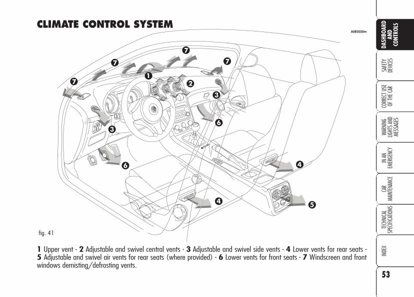
53
SAFE
TYDE
VICES
WARN
ING
LIGHT
S AN
D ME
SSAG
ES
IN AN
EM
ERGE
NCY
CAR
MAIN
TENA
NCE
TECH
NICA
LSP
ECIFI
CATIO
NSIN
DEX
CORR
ECT U
SE
OF TH
E CAR
DASH
BOAR
DAN
DCO
NTRO
LSCLIMATE CONTROL SYSTEM
1 Upper vent - 2 Adjustable and swivel central vents - 3 Adjustable and swivel side vents - 4 Lower vents for rear seats - 5 Adjustable and swivel air vents for rear seats (where provided) - 6 Lower vents for front seats - 7 Windscreen and frontwindows demisting/defrosting vents.
A0E0220m
fig. 41

54
SAFE
TYDE
VICES
WARN
ING
LIGHT
S AN
D ME
SSAG
ESIN
AN
EMER
GENC
YCA
RMA
INTE
NANC
ETE
CHNI
CAL
SPEC
IFICA
TIONS
INDE
XCO
RREC
T USE
OF
THE C
AR
DASH
BOAR
DAN
DCO
NTRO
LS
CENTRAL AND SIDE VENTS fig. 42-43These vents are aligned on the dash-board. Each vent A features a wheel Bto adjust air flow and a device C to di-rect air flow horizontally or vertically.
O = Completely closedI = Completely open
A0E0014mfig. 42 A0E0057mfig. 44
UPPER VENT fig. 44
The vent has an opening/closing con-trol.
O = Completely closed
I = Completely open
WINDSCREEN AND FRONTSIDE WINDOW DEMISTING/DEFROSTING VENTS
These vents are located at the ends (A-fig. 45) and on the front part B of thedashboard.
REAR VENTS (where provided) fig. 46
Each vent A features a wheel B to ad-just air flow and a device C to direct it.O = Completely closedI = Completely open
A0E0012mfig. 43
OFF
O
I
AUTO
AUTO
A0E0088mfig. 46
A0E0067mfig. 45

55
SAFE
TYDE
VICES
WARN
ING
LIGHT
S AN
D ME
SSAG
ES
IN AN
EM
ERGE
NCY
CAR
MAIN
TENA
NCE
TECH
NICA
LSP
ECIFI
CATIO
NSIN
DEX
CORR
ECT U
SE
OF TH
E CAR
DASH
BOAR
DAN
DCO
NTRO
LS
AIR DISTRIBUTIONSELECTION
O: air flow to driver’s/passenger’sbody;
M: air flow to driver’s/passenger’sbody and lower part of the passengercompartment;
N: air flow towards the front and rearlower part of the passenger compartment;
Q: air flow towards the lower part ofthe passenger compartment and wind-screen;
ü: air flow towards the windscreen
MANUAL CLIMATECONTROL SYSTEM (where provided)
CONTROLS fig. 47
A - Air temperature knob (mixing warmand cold air);
B - Air distribution knob;
C - Fan speed knob;
D - Heated rear window and door mir-rors defrosting on/off button;
E - Windscreen, front side windows anddoor mirrors max. demisting/defrostingon/off button;
F - Air recirculation on/off button;
G - Compressor on/off button.
fig. 47 A0E0011m

56
SAFE
TYDE
VICES
WARN
ING
LIGHT
S AN
D ME
SSAG
ESIN
AN
EMER
GENC
YCA
RMA
INTE
NANC
ETE
CHNI
CAL
SPEC
IFICA
TIONS
INDE
XCO
RREC
T USE
OF
THE C
AR
DASH
BOAR
DAN
DCO
NTRO
LS QUICK WINDSCREEN AND FRONT SIDE WINDOWDEMISTING/DEFROSTING(MAX-DEF function)
Press button -: the button leds -,√ and( will turn on. To turn this func-tion off, press again button - the but-ton led will turn off. After defrosting, turnthe function off to keep top comfort con-ditions.
Window demisting
Climate control system √ is very use-ful to speed up window demisting andit is therefore to be turned on in theevent of considerable moisture. In anycase it is recommended to perform thefollowing preventive demisting proce-dure:
❒ turn air recirculation off (if on);
❒ turn knob C to second speed;
❒ turn knob B toQ.
HEATED REAR WINDOWAND DOOR MIRRORDEMISTING/DEFROSTING
Press button ( to activate the demist-ing/defrosting function: when this func-tion is on, the circular led around the but-ton will turn on.
On certain versions, turning this functionon will also activate windscreen de-frosting in the windscreen wiper area.
This function is timed and switches offautomatically after few minutes, or bypressing again the button or by turningthe engine off. It will not be switchedon automatically when restarting the en-gine.
IMPORTANT Do not apply stickers onthe inside of the heated rear windowover the heating filaments to avoid dam-age that might cause it to stop work-ing properly.
WARMING THE PASSENGERCOMPARTMENT
Proceed as follows:
❒ turn knob A to the required temper-ature;
❒ turn knob C to the required speed;
❒ turn knob B to the required distribu-tion:
N: to warm the feet of front and rearpassengers;
M: to warm the feet and keep the facecool (bilevel function);
Q: to warm the feet and at the sametime demist the windscreen;
❒ turn air recirculation off (if on).

57
SAFE
TYDE
VICES
WARN
ING
LIGHT
S AN
D ME
SSAG
ES
IN AN
EM
ERGE
NCY
CAR
MAIN
TENA
NCE
TECH
NICA
LSP
ECIFI
CATIO
NSIN
DEX
CORR
ECT U
SE
OF TH
E CAR
DASH
BOAR
DAN
DCO
NTRO
LSCLIMATE CONTROL (fast cooling)
IMPORTANT The compressor √ canbe enabled only if the ventilation is en-abled.
Proceed as follows:
❒ turn knob A completely leftwards;
❒ turn knob C to top speed;
❒ turn knob B to O;
❒ press buttons √ andv (buttonsleds on).
How to keep the requiredcooling
Proceed as follows:
❒ turn air recirculation off (if on).
❒ turn knob A to the required temper-ature;
❒ turn the knurled ring C to the requiredfan speed.
LOOKING AFTER THESYSTEM
During the winter, the climate controlsystem √ must be turned on at leastonce a month for about ten minutes.
Before summer, have the systemchecked at Alfa Romeo Authorized Ser-vices.
RECIRCULATION
To turn this function on press buttonv: the button led will turn on.
This function is particularly useful whenthe outside air is heavily polluted (in atraffic jam, tunnel, etc.) However, it isbetter not to use it for long periods, es-pecially if there are several people in thecar to prevent window misting up.
Do not use the air recirculation functionon rainy/cold days as it would consid-erably increase the possibility of the win-dows misting inside.
IMPORTANT The inside air recircula-tion system makes it possible to reachthe required (“heating” or “cooling”)conditions faster.
After connecting/dis-connecting the battery,wait for 3 minutes at
least before fitting the electronickey into the ignition device inorder to allow the climate con-trol system control unit to resetthe positions of the electric ac-tuators that adjust air temper-ature and distribution.
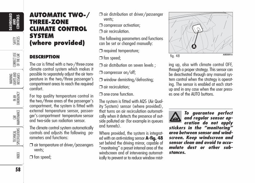
58
SAFE
TYDE
VICES
WARN
ING
LIGHT
S AN
D ME
SSAG
ESIN
AN
EMER
GENC
YCA
RMA
INTE
NANC
ETE
CHNI
CAL
SPEC
IFICA
TIONS
INDE
XCO
RREC
T USE
OF
THE C
AR
DASH
BOAR
DAN
DCO
NTRO
LS
To guarantee perfectand regular sensor op-eration do not apply
stickers in the “monitoring”area between sensor and wind-screen. Keep windscreen andsensor clean and avoid to accu-mulate dust or other sub-stances.
AUTOMATIC TWO-/THREE-ZONECLIMATE CONTROLSYSTEM(where provided)
DESCRIPTION
The car is fitted with a two-/three-zoneclimate control system which makes itpossible to separately adjust the air tem-perature in the two/three passenger’scompartment areas to reach the requiredcomfort.
For top quality temperature control inthe two/three areas of the passenger'scompartment, the system is fitted withexternal temperature sensor, passen-ger's compartment temperature sensorand two-side sun radiation sensor.
The climate control system automaticallycontrols and adjusts the following pa-rameters and functions:
❒ air temperature at driver/passengersvents;
❒ fan speed;
❒ air distribution at driver/passengervents;
❒ compressor activation;❒ air recirculation.
The following parameters and functionscan be set or changed manually:
❒ required temperature;
❒ fan speed;
❒ air distribution on seven levels ;
❒ compressor on/off;
❒ window demisting/defrosting;
❒ air recirculation;
❒ one-zone function.
The system is fitted with AQS (Air Qual-ity System) sensor (where provided),that turns on air recirculation automati-cally when it detects the presence of out-side polluted air (for example in queuesand tunnels).
Where provided, the system is integrat-ed with an anti-misting sensor A-fig. 48set behind the driving mirror, capable of“monitoring” a preset internal area of thewindscreen and of intervening automat-ically to prevent or to reduce window mist-
A0E0091mfig. 48
ing up, also with climate control OFF,through a proper strategy. This sensor canbe deactivated through any manual sys-tem control when the strategy is operat-ing. The sensor is enabled at each start-up and in any case when the user press-es one of the AUTO buttons.
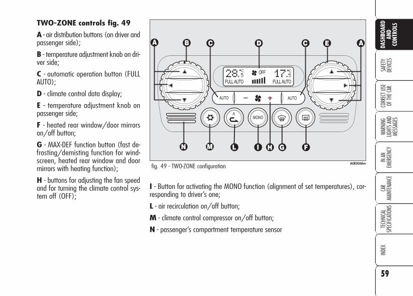
59
SAFE
TYDE
VICES
WARN
ING
LIGHT
S AN
D ME
SSAG
ES
IN AN
EM
ERGE
NCY
CAR
MAIN
TENA
NCE
TECH
NICA
LSP
ECIFI
CATIO
NSIN
DEX
CORR
ECT U
SE
OF TH
E CAR
DASH
BOAR
DAN
DCO
NTRO
LS
I - Button for activating the MONO function (alignment of set temperatures), cor-responding to driver’s one;
L - air recirculation on/off button;
M - climate control compressor on/off button;
N - passenger’s compartment temperature sensor
TWO-ZONE controls fig. 49
A - air distribution buttons (on driver andpassenger side);
B - temperature adjustment knob on dri-ver side;
C - automatic operation button (FULLAUTO);
D - climate control data display;
E - temperature adjustment knob onpassenger side;
F - heated rear window/door mirrorson/off button;
G - MAX-DEF function button (fast de-frosting/demisting function for wind-screen, heated rear window and doormirrors with heating function);
H - buttons for adjusting the fan speedand for turning the climate control sys-tem off (OFF);
fig. 49 - TWO-ZONE configurationA0E0058m

60
SAFE
TYDE
VICES
WARN
ING
LIGHT
S AN
D ME
SSAG
ESIN
AN
EMER
GENC
YCA
RMA
INTE
NANC
ETE
CHNI
CAL
SPEC
IFICA
TIONS
INDE
XCO
RREC
T USE
OF
THE C
AR
DASH
BOAR
DAN
DCO
NTRO
LS THREE-ZONE controls fig. 50Front controlsA - air distribution buttons (driver and pas-senger side);B - temperature adjustment knob on driverside;C - automatic operation button (FULL AUTO);D - climate control data display;E - temperature adjustment knob on passen-ger side;F - heated rear window/door mirrors on/offbutton;G - MAX-DEF function button (fast defrost-ing/demisting function for windscreen, heat-ed rear window and door mirrors with heatingfunction);H - buttons for adjusting the fan speed andfor turning the climate control system off(OFF);I - Button for activating the MONO function(alignment of set temperatures), correspond-ing to driver’s one;L - air recirculation on/off button;M - climate control compressor on/off button;N - passenger’s compartment temperaturesensor
Rear controlsP - knob for adjusting temperature on rearpassenger side;Q - button for turning on automatic operation(FULL AUTO) and for turning off air flow torear seats (OFF); R - air distribution buttons;S - rear temperature display.
fig. 50 - THREE-ZONE configuration - Front and rear controls A0E0059m

61
SAFE
TYDE
VICES
WARN
ING
LIGHT
S AN
D ME
SSAG
ES
IN AN
EM
ERGE
NCY
CAR
MAIN
TENA
NCE
TECH
NICA
LSP
ECIFI
CATIO
NSIN
DEX
CORR
ECT U
SE
OF TH
E CAR
DASH
BOAR
DAN
DCO
NTRO
LSAIR TEMPERATUREADJUSTMENT KNOBS
Turning the knob knurled rings (B/E/P), clockwise or counter-clockwise,respectively raises or lowers the tem-perature of the air required respective-ly in the left front zone (knob B) or rightfront zone (knob E) or rear zone (knobP) of the passenger compartment. Thetemperatures set are shown on the dis-play D/S.
Turning the knob knurled rings fullyclockwise or counter-clockwise until theyreach the extreme selections HI or LO,the maximum heating or cooling func-tions are respectively engaged.
HI function (HIGH)(maximum heating power)
It is switched on by setting a tempera-ture of more than 32°C on the display,and can be switched on independentlyfrom the driver’s or passengers’ side, orboth of them; this setting brings the sys-tem to the “one-zone” mode and it isshown by both displays.
This functions can be switched on whenyou wish to heat the passenger com-partment as quickly as possible, by tak-ing the greatest advantage from the sys-tem potential.
The function uses the maximum tem-perature of the heating fluid, whereasair distribution and fan speed are con-trolled automatically by the system.
SWITCHING THE CLIMATECONTROL SYSTEM ON
The system can be turned on by press-ing any button (excluding (,v andMONO); it is however advisable to setthe required temperatures on the displayand then to press the AUTO button.
The climate control system allows to per-sonalise required temperatures (driver andpassengers).
62
SAFE
TYDE
VICES
WARN
ING
LIGHT
S AN
D ME
SSAG
ESIN
AN
EMER
GENC
YCA
RMA
INTE
NANC
ETE
CHNI
CAL
SPEC
IFICA
TIONS
INDE
XCO
RREC
T USE
OF
THE C
AR
DASH
BOAR
DAN
DCO
NTRO
LS LO (LOW) function (highest cooling power)
It is switched on by setting a tempera-ture lower than 16°C on the display;this setting is shown on the display. Thisfunction can be switched on when youwish to cool the passenger compartmentas quickly as possible, by taking thegreatest advantage from the system po-tential.
The function cuts off air heating, switch-es on both internal air recirculation (toprevent hot air from entering the com-partment) and the climate control com-pressor, brings air distribution to ̄ /˙and the fan speed is controlled auto-matically by the system.
With the function switched on, howev-er, all the manual settings can be made.To switch the function off, you only needto turn the ring of knob B/E/P of thetemperature set to a value higher than16°C; the opposite display and the reardisplay (where provided) will show16°C.
Pressing button AUTO, the display willshow a temperature of 16°C and re-turns to an operating condition with au-tomatic temperature adjustment.
This function should not be ac-tivated when the engine is cold,to prevent air not warm enoughfrom entering the passengercompartment.
With the function switched on, howev-er, all the manual settings can be made.To switch the function off, you only needto turn the ring of knob (B or E/P) ofthe temperature set to a value lowerthan 32°C; the opposite display and therear display (where provided) will show32°C.
Pressing button AUTO, the display willshow a temperature of 32°C and re-turns to an operating condition with au-tomatic temperature adjustment.

63
SAFE
TYDE
VICES
WARN
ING
LIGHT
S AN
D ME
SSAG
ES
IN AN
EM
ERGE
NCY
CAR
MAIN
TENA
NCE
TECH
NICA
LSP
ECIFI
CATIO
NSIN
DEX
CORR
ECT U
SE
OF TH
E CAR
DASH
BOAR
DAN
DCO
NTRO
LSFAN SPEED ADJUSTMENT
Press buttons +/– to increase or to de-crease the fan speed.
The fan speed is shown by the lit bars onthe display:
❒ min fan speed = one bar lit;
❒ max fan speed = 6 bars lit;
At starting, if climate control system isoperating in automatic mode, the fanspeed is kept at minimum until the en-gine has started.
With compressor on and engine running,the fan speed cannot fall below the min.speed.
The fan can be cut off (all bars off) on-ly if the climate control compressor hasbeen switched off by pressing button √.
To restore automatic fan speed controlafter a manual adjustment, press but-tons AUTO.
AUTO will also go off if the system (spe-cially when compressor is turned offmanually) cannot reach or cannot keepthe required temperature.
Button √ will not turn off AUTO if thesystem can keep the required comfort.
It is inadvisable to useair recirculation on
rainy/cold days as it wouldconsiderably increase the pos-sibility of windows misting upinside.
WARNING
AUTOMATIC OPERATION(AUTO BUTTON)
Pressing button AUTO (front and rearcontrols) the displays will show FULL AU-TO and the system will automatically ad-just:
❒ fan speed;
❒ air distribution in passenger com-partment;
❒ air recirculation;
❒ compressor;
and it will cancel all the previous man-ual adjustments.
Wording FULL will disappear from thedisplay of the involved area (driver orfront passenger side or rear passengerside) when performing whatever oper-ation (excluding temperature change).

64
SAFE
TYDE
VICES
WARN
ING
LIGHT
S AN
D ME
SSAG
ESIN
AN
EMER
GENC
YCA
RMA
INTE
NANC
ETE
CHNI
CAL
SPEC
IFICA
TIONS
INDE
XCO
RREC
T USE
OF
THE C
AR
DASH
BOAR
DAN
DCO
NTRO
LS The MAX-DEF function activates the fol-lowing operations:
❒ rear panel turning off;
❒ air flow increase;
❒ air distribution at DEF;
❒ outside air intake;
❒ compressor activation;
❒ AQS function deactivation (whereprovided)
❒ rear window heating activation.
When the MAX-DEF function is on, theonly manual operations possible aremanual adjustment of the fan speed andswitching heated rear window off.
IMPORTANT If the engine is notwarm enough, the function will not en-gage the predefined fan speed imme-diately, to limit the flow to the passen-ger compartment of air that is not warmenough to demist the windows.
Pressing again one of the following but-tons:v,√, AUTO, MONO or - thesystem switches off the MAX-DEF func-tion, resuming the system operating con-ditions prior to turning it on, in additionto activating the last function required,if any.
IMPORTANT Don’t turn the MAX-DEFfunction on with engine off to preventdraining the battery.
QUICK FRONT WINDOWDEMISTING/DEFROSTING(MAX-DEF function)
Pressing button - the climate controlautomatically activates timed operationof all the functions required to quickendemisting/defrosting of the windscreenand front side windows and, on certainversions, electric windscreen demistingin the windscreen wiper area.
The MAX-DEF can be turned on also withengine off. When this function is on thecircular led around the button will turn on.

65
SAFE
TYDE
VICES
WARN
ING
LIGHT
S AN
D ME
SSAG
ES
IN AN
EM
ERGE
NCY
CAR
MAIN
TENA
NCE
TECH
NICA
LSP
ECIFI
CATIO
NSIN
DEX
CORR
ECT U
SE
OF TH
E CAR
DASH
BOAR
DAN
DCO
NTRO
LSALIGNING SETTEMPERATURES (MONO function)
Pressing button MONO automaticallyaligns the temperature and air distribu-tion on front and rear passenger areawith that on the driver area.
When this function is on, the circular ledaround the button will turn on.
Turn knob B to set the same tempera-ture between the two/three zones.
Separate operation of set temperatures(front and rear passengers) is restoredautomatically by turning knob E or P orby pressing again button MONO, the cir-cular led around the button will turn off.
IMPORTANT Operating the rear con-trols (Three-zone configuration) will turnoff the MONO function and the relevantcircular led around the MONO button.
CLIMATE CONTROL COMPRESSOR ON/OFF
Press button √ to turn the compressoron: when climate control compressor ison the circular led around the button willturn on. Compressor will stay on also af-ter turning the engine off.
To turn the compressor off press againbutton √.
HEATED REAR WINDOWAND DOOR MIRRORDEMISTING/DEFROSTING
Press button ( to activate the demist-ing/defrosting function: when this func-tion is on, the circular led around the but-ton will turn on.
On certain versions, turning this functionon will also activate windscreen de-frosting in the windscreen wiper area.
This function is timed and switches offautomatically after few minutes, or bypressing again the button or by turningthe engine off. It will not be switchedon automatically when restarting the en-gine.
IMPORTANT Do not apply stickers onthe inside of the rear window over theheating filaments to avoid damage thatmight cause it to stop working properly.

66
SAFE
TYDE
VICES
WARN
ING
LIGHT
S AN
D ME
SSAG
ESIN
AN
EMER
GENC
YCA
RMA
INTE
NANC
ETE
CHNI
CAL
SPEC
IFICA
TIONS
INDE
XCO
RREC
T USE
OF
THE C
AR
DASH
BOAR
DAN
DCO
NTRO
LS
AIR DISTRIBUTIONSELECTION
Front seat Two-zone/Three-zone configuration
Pressing buttons (front controls)N/O/˙ you can manually chooseone of the 7 possible modes for air dis-tribution inside the compartment:
˙ Flow of air to the dashboard centreand side outlets (passenger’s body).
O˙ Splitting of the air flow between
the vents to the lower part of thepassenger compartment (warmestair) and the dashboard centre andside outlets and the rear outlet(coolest air).
O Air flow towards the front and rearlower part of the passenger com-partment. This type of distribution al-lows heating of the passenger com-partment in the shortest time byproper setting of the temperature.
N Splitting of the air flow between O windscreen and front side window
demisting/defrosting vents and thelower part of the passenger com-partment. This type of air distribu-tion allows satisfactory heating ofthe passenger compartment whilepreventing possible misting of thewindows.
N Air flow to the windscreen and frontside window vents to demist or de-frost them.
N˙
Splitting of the air flow betweenthe central/side dashboard vents,rear vents and windscreen andside window defrosting/demistingvents. This type of air distributionallows satisfactory ventilation ofthe passenger compartment whilepreventing possible misting of thewindows.
With compressor off, the system willcheck whether outside temperature ishigher or lower/same as the set one:
❒ if outside temperature is lower thanthe set one, the system will operateregularly also with compressor off;
❒ if outside temperature is higher thanthe set one, the system will not beable to keep the required condition,the set temperature values will thenstart to flash on the display.
Temperature detection (compressor offand outside temperature higher than settemperature) is activated each time theelectronic key is fitted into the ignitiondevice.
Operation of the cli-mate control compres-
sor is necessary for coolingand dehumidifying the air; it isadvisable to keep this functionalways on, to prevent windowmisting problems.
WARNING

67
SAFE
TYDE
VICES
WARN
ING
LIGHT
S AN
D ME
SSAG
ES
IN AN
EM
ERGE
NCY
CAR
MAIN
TENA
NCE
TECH
NICA
LSP
ECIFI
CATIO
NSIN
DEX
CORR
ECT U
SE
OF TH
E CAR
DASH
BOAR
DAN
DCO
NTRO
LSN˙
Splitting of the air flow between
Oall vents.
Rear seat Three-zoneconfiguration controls
Pressing buttons N/O(rear controls)you can manually choose one of the 3possible modes for air distribution to therear side of passenger's compartment
N Air flow to the vents on the centralconsole (passengers’ body).
O Air flow towards the rear lower partof the passenger compartment. Thistype of distribution allows heating of thepassenger compartment in the shortesttime by proper setting of the tempera-ture.
N Splitting of the air flow betweenO the vents to the lower part of thepassenger compartment (warmest air)and the rear vents (coolest air).
To restore automatic air distribution con-trol after a manual selection, press but-tons AUTO (front controls) or AUTO (rearcontrols).
AIR RECIRCULATION ANDAQS FUNCTION (AIRQUALITY SYSTEM)ON/OFF (where provided)
Inside air recirculation is controlled ac-cording to the following operating log-ics:
❒ automatic control, indicated by but-ton led “A”;
❒ forced switching on (inside air recir-culation always on), indicated by theturning on of the circular led aroundthe button;
❒ forced switching off (air recirculationalways off with air inlet from the out-side), indicated by the turning off ofthe circular led around the button.
With A.Q.S. (air quality sensor - whereprovided), the operating logics becomessequential by pressing button v.
IMPORTANT The inside air recircula-tion system makes it possible to reachthe required heating or cooling condi-tions faster. It is however inadvisable touse it on rainy/cold days as it wouldconsiderably increase the possibility ofthe windows misting inside, especiallyif the climate control compressor is off.It is advisable to turn on the inside airrecirculation system in queues or tunnelsto avoid admitting polluted air from out-side. The prolonged use of this functionshould however be avoided, especiallywith several persons on board, to avoidthe possibility of the windows mistinginside and to guarantee the requiredfresh air inlet.

68
SAFE
TYDE
VICES
WARN
ING
LIGHT
S AN
D ME
SSAG
ESIN
AN
EMER
GENC
YCA
RMA
INTE
NANC
ETE
CHNI
CAL
SPEC
IFICA
TIONS
INDE
XCO
RREC
T USE
OF
THE C
AR
DASH
BOAR
DAN
DCO
NTRO
LS POLLEN FILTER/ ACTIVATEDCARBON POLLEN FILTER
According to versions, the car can be fit-ted with pollen filter or activated carbonpollen filter (where provided). The filterhas the specific capability of admitting tothe passenger compartment purified air,free from particles such as dust, pollen,etc. The filtering action takes place un-der all air inlet conditions and it is clear-ly most effective with the windows shut.Have the conditions of the filter checkedby Alfa Romeo Authorized Services atleast once a year, preferably at the on-set of summer. If the car is used main-ly in polluted or dusty areas it should bechecked and if necessary replaced atshorter intervals than specified in theService Schedule (see section “CarMaintenance”).
AQS function (Air QualitySystem) (where provided)
The AQS function turns on automatical-ly air recirculation when it detects thepresence of polluted air (e.g. in queuesand tunnels).
IMPORTANT With AQS function on,after a preset time with recirculation on,the compressor will enable outside airinlet (for about 1 minute) to change airinside the passenger compartment, re-gardless of outside air pollution level.
IMPORTANT The AQS function is dis-abled when the outside temperature iscold to prevent window misting up. Toreactivate this function, press buttonv. Led “A” on button v willturn on to indicate that the function ison.
Failure to replace the fil-ter may considerably re-duce the effectiveness of
the climate control system up toblocking the air flow from theoutlets and vents.
In certain weather con-ditions (e.g. outsidetemperature around
0°C) and with automatic air re-circulation control on, mist mayform on the windows. In thiscase press button v toswitch off recirculation and ifnecessary press button + to in-crease the flow of air to thewindscreen.
With the outside tem-perature below -1°C theclimate control compres-
sor is unable to work. It istherefore inadvisable to use theinside air recirculation functionwith low outside temperatureas windows may mist overquickly.

69
SAFE
TYDE
VICES
WARN
ING
LIGHT
S AN
D ME
SSAG
ES
IN AN
EM
ERGE
NCY
CAR
MAIN
TENA
NCE
TECH
NICA
LSP
ECIFI
CATIO
NSIN
DEX
CORR
ECT U
SE
OF TH
E CAR
DASH
BOAR
DAN
DCO
NTRO
LSSWITCHING THE CLIMATECONTROL SYSTEM OFF
Keep pressed button “–“ until the dis-play shows OFF.
With climate control system off:
❒ the system stores performed opera-tions;
❒ the display is off (OFF wording is dis-played);
❒ air recirculation is active (button ledon);
❒ compressor is active;
❒ ventilation is off.
To turn the climate control system onagain press button AUTO or any otherbutton (excluding (, v andMONO). Turning the climate control sys-tem on again, air recirculation will beagain controlled automatically.
Pressing button OFF on the rear controlwill display the wording OFF on the reardisplay and will stop air flow to rearseats.
ADDITIONALHEATER (dieselversions only) (where provided)
The car is fitted with an additional heaterthat supports the engine during cold orwinter weather to quickly reach a com-fortable temperature in the passengercompartment.
The additional heater works with the en-gine running when the outside temper-ature is below 20°C and the engine hasnot yet reached normal operating tem-perature.
After connecting/dis-connecting the battery,wait for 3 minutes at
least before fitting the electronickey into the ignition device inorder to allow the climate con-trol system control unit to resetthe positions of the electric ac-tuators that adjust air temper-ature and distribution.
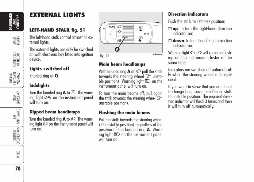
70
SAFE
TYDE
VICES
WARN
ING
LIGHT
S AN
D ME
SSAG
ESIN
AN
EMER
GENC
YCA
RMA
INTE
NANC
ETE
CHNI
CAL
SPEC
IFICA
TIONS
INDE
XCO
RREC
T USE
OF
THE C
AR
DASH
BOAR
DAN
DCO
NTRO
LS EXTERNAL LIGHTS
LEFT-HAND STALK fig. 51
The left-hand stalk control almost all ex-ternal lights.
The external lights can only be switchedon with electronic key fitted into ignitiondevice.
Lights switched off
Knurled ring at O.
Sidelights
Turn the knurled ring A to6. The warn-ing light 3 on the instrument panelwill turn on.
Dipped beam headlamps
Turn the knurled ring A to2. The warn-ing light 2 on the instrument panel willturn on.
Main beam headlamps
With knurled ring A at 2 pull the stalktowards the steering wheel (2nd unsta-ble position). Warning light 1 on theinstrument panel will turn on.
To turn the main beams off, pull againthe stalk towards the steering wheel (2nd
unstable position).
Flashing the main beams
Pull the stalk towards the steering wheel(1st unstable position) regardless of theposition of the knurled ring A. Warn-ing light 1 on the instrument panelwill turn on.
Direction indicators
Push the stalk to (stable) position:
❒ up: to turn the right-hand directionindicator on;
❒ down: to turn the left-hand directionindicator on.
Warning light Î or¥will come on flash-ing on the instrument cluster at thesame time.
Indicators are switched off automatical-ly when the steering wheel is straight-ened.
If you want to show that you are aboutto change lane, move the left-hand stalkto unstable position. The required direc-tion indicator will flash 3 times and thenit will turn off automatically.
A0E0064mfig. 51

71
SAFE
TYDE
VICES
WARN
ING
LIGHT
S AN
D ME
SSAG
ES
IN AN
EM
ERGE
NCY
CAR
MAIN
TENA
NCE
TECH
NICA
LSP
ECIFI
CATIO
NSIN
DEX
CORR
ECT U
SE
OF TH
E CAR
DASH
BOAR
DAN
DCO
NTRO
LS“FOLLOW ME HOME”DEVICE
This function allows the illumination ofthe space in front of the car for a pre-set period of time.
Activation
Pull the stalk towards the steering wheelwithin 2 minutes from when the engineis turned off.
At each single movement of the stalk,the staying on of the lights is extendedby 30 seconds up to a maximum of 3.5minutes; then the lights are switched offautomatically.
Each time the stalk is operated, the 3warning light turns on together with themessage on the display (see section“Warning lights and messages”).
Deactivation
Keep the stalk pulled towards the steer-ing wheel for more than 2 seconds.
AUTOMATIC HEADLIGHTSSENSOR (daylight sensor)(where provided)
It detects the changes of the externallight intensity of the car according to thelight sensitivity set: the greater the sen-sitivity is, the smaller the amount of ex-ternal light necessary to control theswitching-on of the external headlightswill be.
On certain versions, the daylight sen-sor sensitivity can be adjusted throughthe “Setup Menu” of the display (seesection “Reconfigurable multifunctiondisplay” in this section).
Activation
Turn the knurled ring A-fig. 51 to2A :in this way, the automatic activation ofthe side/taillights and dipped beamheadlights is simultaneously enabled ac-cording to outside brightness.
With lights switched on automaticallyand in the presence of a switching offcontrol by the sensor, the main beamswill be switched off first and a few sec-onds after also the sidelights.
Deactivation
As a result of the sensor control, thedipped beam headlights will switch offand, after a few seconds, sidelights willswitch off too. The sensor is not ableto detect the fog presence, under thiscondition lights shall therefore beswitched on manually.
Failure warnings
On certain versions headlight sensor fail-ure is shown by the instrument panelwarning light 1, whereas on other ver-sions a dedicated message is shown onthe display (see section “Warning lightsand messages”).

72
SAFE
TYDE
VICES
WARN
ING
LIGHT
S AN
D ME
SSAG
ESIN
AN
EMER
GENC
YCA
RMA
INTE
NANC
ETE
CHNI
CAL
SPEC
IFICA
TIONS
INDE
XCO
RREC
T USE
OF
THE C
AR
DASH
BOAR
DAN
DCO
NTRO
LS Parking lights
With instrument panel off they turn onby pressing button C. When pressing thebutton a buzzer will sound and the in-strument panel warning light 3 willturn on.
Press the button again to turn the lightsoff.
With parking lights on, move the exter-nal lights left-hand stalk upwards ordownwards to select on which side(right or left) the lights must stay on. Inthis event warning light 3 will turnoff.
With left stalk at central position the fourparking lights and the number plate lightwill turn on.
DASHBOARD BUTTONS fig. 52
Front fog lights (where provided)
To turn front fog lights on, press buttonA; to activate these lights it is necessaryto have the side/taillights switched on.The instrument panel warning light 5will turn on. Press the button again or turnside/taillights off to turn the lights off.
Rear fog lights
To turn rear fog lights on, press buttonB to activate these lights it is necessaryto have the dipped beams or front foglights switched on. The instrument pan-el warning light 4will turn on. They turnoff by pressing the button again, turn-ing the front or rear fog lights off or byturning the engine off.
A0E0061mfig. 52
Hazard lights
These lights are turned on by pressingbutton A-fig. 53.
When these lights are on, the switchflashes and warning lights Î and¥ onthe instrument panel will turn on at thesame time.
Press switch A again to turn the lightsoff.
Use of the hazardwarning lights is ruled
by the Highway Code of thecountry in which the car isused. Observe regulations.
WARNING
A0E0100mfig. 53

73
SAFE
TYDE
VICES
WARN
ING
LIGHT
S AN
D ME
SSAG
ES
IN AN
EM
ERGE
NCY
CAR
MAIN
TENA
NCE
TECH
NICA
LSP
ECIFI
CATIO
NSIN
DEX
CORR
ECT U
SE
OF TH
E CAR
DASH
BOAR
DAN
DCO
NTRO
LSWINDOW WASHING
RIGHT-HAND STALK
Right-hand stalk fig. 54 controls wind-screen washer/wiper operation.
With external lights on, activating thewindscreen washer will also activate theheadlight washer, if provided.
Windscreen washer/wiper
The stalk can be moved to five differentpositions:
0: windscreen wiper off;
1: intermittent.
With the stalk in position 1, turning theknurled ring A four possible intermittentspeeds are obtained:
■ = slow intermittent
■ = intermittent medium
■ = intermittent medium-fast
■ = fast intermittent
2: continuous slow
3: continuous fast
4: fast temporary (unstable position)
Operation in position 4 is limited to thetime the stalk is held in this position.When the stalk is released, it returnsto position 0 automatically stopping thewiper.
A0E0066mfig. 54
Never use the windowwiper to remove ice orsnow from the wind-
screen. In these conditions, thewiper is submitted to excessiveeffort that results in motor pro-tection cutting in and wiper op-eration inhibition for few secondsas a consequence. If operation isnot restored contact Fiat Dealer-ship.

74
SAFE
TYDE
VICES
WARN
ING
LIGHT
S AN
D ME
SSAG
ESIN
AN
EMER
GENC
YCA
RMA
INTE
NANC
ETE
CHNI
CAL
SPEC
IFICA
TIONS
INDE
XCO
RREC
T USE
OF
THE C
AR
DASH
BOAR
DAN
DCO
NTRO
LS Turning the knurled ring A-fig. 54 itis possible to increase the sensitivity ofthe rain sensor, obtaining a quickerchange from stationary (no wiping)when the windscreen is dry, to first con-tinuous speed (continuous, slow). A fur-ther stroke will confirm operation.
Operating the windscreen washer withthe rain sensor activated (stalk at posi-tion 1-fig. 54) the normal washingcycle is performed at the end of whichthe rain sensor resumes its normal au-tomatic function.
Removing the electronic key from theignition device, the rain sensor is deac-tivated and the next time the engine isstarted it will not be reactivated even ifthe stalk has remained in position 1-fig. 54. In this case to activate the rainsensor, simply move the stalk to 0 or 2and then back to 1.
When the rain sensor is reactivated inthis way, the wiper performs one stroke,even if the windscreen is dry, to indicatethat reactivation has occurred.
“Smart washing” function
Pulling the lever towards the steeringwheel (unstable position) operates thewindscreen washer.
Keeping the stalk pulled with just onemovement it is possible to operate thewasher jet and the wiper at the sametime; the wiper actually comes into op-eration automatically when the stalk ispulled for more than half a second.
The wiper stops working 3 strokes afterreleasing the stalk; a further stroke af-ter about 6 seconds will complete thewiping operation.
RAIN SENSOR (where provided)
The rain sensor A-fig. 55, located be-hind the driving mirror, is an electronic de-vice combined with the windscreen wiperwhich has the purpose of automaticallyadjusting the number of wipes to intensi-ty of the rain. All the other functions con-trolled by the right-hand stalk remain un-changed.
The rain sensor is activated automati-cally moving the right-hand stalk to po-sition 1-fig. 54 and it has a range ofadjustment that gradually varies be-tween wiper stationary (no wiping)when the windscreen is dry, to wiperat second speed (continuous, mediumwiping) with heavy rain.
A0E0227mfig. 55

75
SAFE
TYDE
VICES
WARN
ING
LIGHT
S AN
D ME
SSAG
ES
IN AN
EM
ERGE
NCY
CAR
MAIN
TENA
NCE
TECH
NICA
LSP
ECIFI
CATIO
NSIN
DEX
CORR
ECT U
SE
OF TH
E CAR
DASH
BOAR
DAN
DCO
NTRO
LS
HEADLIGHT WASHERS (where provided) fig. 56
Headlight washers are visible and are fit-ted with a nozzle for each external lightfunction. They come into operation au-tomatically when operating the wind-screen washer with external lightsturned on.
IMPORTANT Check at regular inter-vals correct operation and cleanness ofnozzles.
IMPORTANT In the event of rain sen-sor failure, windscreen wiper operationwith right-hand stalk at 1-fig. 54 shallbe intermittent. If failure occurs duringautomatic operation, the system willkeep the last wiper operating condition.Operation is however guaranteed al-though moving the stalk to other posi-tions.
The rain sensor is able to recognize andautomatically adjust itself in the pres-ence of the following particular condi-tions:
❒ impurities on the controlled surface(salt, dirt, etc.);
❒ difference between day and night.
Failure warnings
On certain versions rain sensor failure isshown by the instrument panel warninglightu, whereas on other versions adedicated message is shown on the dis-play (see section “Warning lights andmessages”).
Rain sensor shall be de-activated when washingthe car at automatic car-
wash.
Make sure the rain sen-sor is deactivated ifthere is ice on the wind-
screen.
Make sure the device isoff when cleaning the
windscreen.
WARNING
A0E0046mfig. 56
Streaks of water couldcause unrequired blademovements.

76
SAFE
TYDE
VICES
WARN
ING
LIGHT
S AN
D ME
SSAG
ESIN
AN
EMER
GENC
YCA
RMA
INTE
NANC
ETE
CHNI
CAL
SPEC
IFICA
TIONS
INDE
XCO
RREC
T USE
OF
THE C
AR
DASH
BOAR
DAN
DCO
NTRO
LS CRUISE CONTROL(where provided)
GENERAL
The speed regulator (CRUISE CON-TROL), with electronic control, makesit possible to drive the car at the requiredspeed, without pressing the acceleratorpedal. This reduces driving fatigue dur-ing long journeys (specially on high-ways) because the speed memorised isautomatically maintained.
IMPORTANT The Cruise Control mustbe activated at speeds of between 45and 180 k.p.h., in fourth, fifth and sixthgears.
A0E0095mfig. 57
DEVICE ENGAGEMENT
Turn knurled ring A-fig. 57 toÜ.
The device cannot be engaged in firstspeed or reverse. It is recommended toengage it in 4th or higher speeds. Trav-elling downhill with the device engaged,the car speed may increase more thanthe memorised one.
When the device is activated the in-strument panel warning light Ü turnson (on certain versions together with amessage on the display) (see section“Warning lights and messages”).
TO MEMORISE SPEED
Proceed as follows:
❒ turn the knurled ring A-fig. 57 toÜ and press the accelerator pedal tothe required speed;
❒ push the stalk upwards (+) or down-wards (–), then release it: car speedis memorised and it is therefore pos-sible to release the accelerator ped-al.
In the case of need (when overtakingfor instance) acceleration is possible sim-ply pressing the accelerator pedal: re-leasing the accelerator pedal, the car willreturn to the speed memorised previ-ously.
TO RESET THE MEMORISEDSPEED
If the device has been disengaged forexample pressing the brake or clutchpedal, the memorised speed can be re-set as follows:
❒ accelerate gradually until reaching aspeed approaching the one memo-rised;

77
SAFE
TYDE
VICES
WARN
ING
LIGHT
S AN
D ME
SSAG
ES
IN AN
EM
ERGE
NCY
CAR
MAIN
TENA
NCE
TECH
NICA
LSP
ECIFI
CATIO
NSIN
DEX
CORR
ECT U
SE
OF TH
E CAR
DASH
BOAR
DAN
DCO
NTRO
LS❒ pressing the brake pedal, pressing theclutch pedal (in these cases the laststored speed will stay memorised, toresume it press button RES);
❒ pressing the accelerator pedal; in thiscase the system is disengaged onlytemporarily; device operation will beresumed automatically when releas-ing the pedal;
❒ with car speed below the preset lim-it (in these cases the last storedspeed will stay memorised, to resumeit press button RES);
Automatic Cruise Controldeactivation
The Cruise Control is temporarily deac-tivated when the ABS or VDC systemscome into operation (above a max. pre-set time): in this case the last set speedwill stay memorised, to recall it pressbutton RES.
In the event of Cruise Control or enginecontrol system failure, the device is de-activated until removing the electronickey from the ignition device. In thisevent contact Alfa Romeo AuthorizedServices.
❒ engage the gear selected at the timeof speed memorising (4th or 5thgear);
❒ press the RES button (set at stalkend).
TO INCREASE THEMEMORISED SPEED
The speed memorised can be increasedin two ways:
❒ pressing the accelerator and thenmemorising the new speed reached;
or
❒ moving the stalk upwards (+).
Each operation of the stalk will corre-spond to a slight increase in speed(about 1.5 km/h), while keeping thestalk upwards will correspond to a con-tinuous speed increase.
TO REDUCE MEMORISEDSPEED
The speed memorised can be increasedin two ways:
❒ disengaging the device and thenmemorising the new speed;
or
❒ moving the stalk downwards (–) un-til reaching the new speed which willbe memorised automatically.
Each operation of the stalk will corre-spond to a slight decrease in speed(about 1.5 km/h), while keeping thestalk downwards will correspond to acontinuous speed decrease.
DEVICE DISENGAGEMENT
The device is disengaged in one of thefollowing cases:
❒ turning the knurled ring A-fig. 57to O;
❒ turning the engine off or removingthe electronic key from the ignitiondevice;
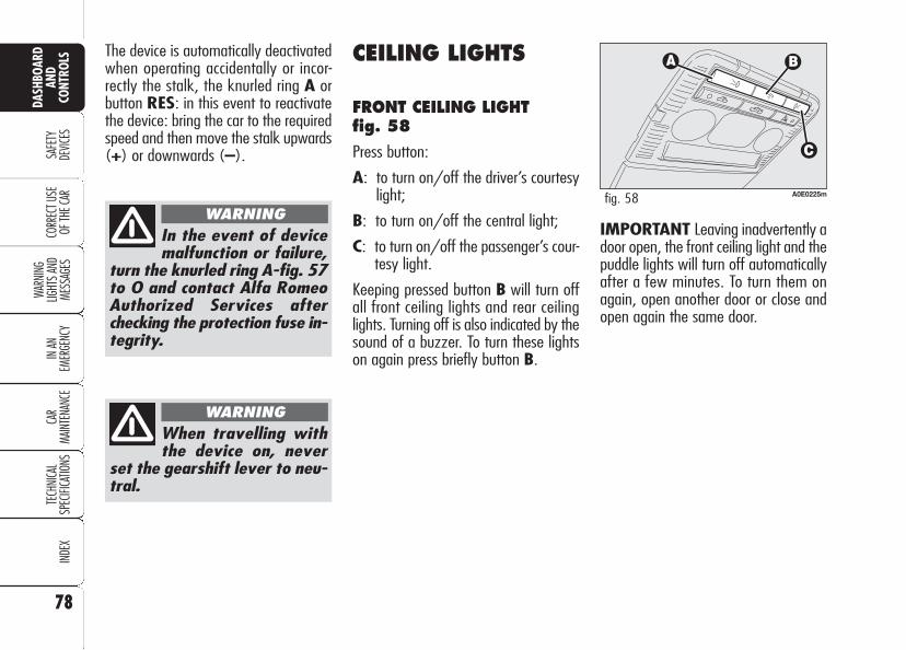
78
SAFE
TYDE
VICES
WARN
ING
LIGHT
S AN
D ME
SSAG
ESIN
AN
EMER
GENC
YCA
RMA
INTE
NANC
ETE
CHNI
CAL
SPEC
IFICA
TIONS
INDE
XCO
RREC
T USE
OF
THE C
AR
DASH
BOAR
DAN
DCO
NTRO
LS The device is automatically deactivatedwhen operating accidentally or incor-rectly the stalk, the knurled ring A orbutton RES: in this event to reactivatethe device: bring the car to the requiredspeed and then move the stalk upwards(+) or downwards (–).
CEILING LIGHTS
FRONT CEILING LIGHT fig. 58
Press button:
A: to turn on/off the driver’s courtesylight;
B: to turn on/off the central light;
C: to turn on/off the passenger’s cour-tesy light.
Keeping pressed button B will turn offall front ceiling lights and rear ceilinglights. Turning off is also indicated by thesound of a buzzer. To turn these lightson again press briefly button B.
In the event of devicemalfunction or failure,
turn the knurled ring A-fig. 57to O and contact Alfa RomeoAuthorized Services afterchecking the protection fuse in-tegrity.
WARNING
When travelling withthe device on, never
set the gearshift lever to neu-tral.
WARNING
A0E0225mfig. 58
IMPORTANT Leaving inadvertently adoor open, the front ceiling light and thepuddle lights will turn off automaticallyafter a few minutes. To turn them onagain, open another door or close andopen again the same door.

79
SAFE
TYDE
VICES
WARN
ING
LIGHT
S AN
D ME
SSAG
ES
IN AN
EM
ERGE
NCY
CAR
MAIN
TENA
NCE
TECH
NICA
LSP
ECIFI
CATIO
NSIN
DEX
CORR
ECT U
SE
OF TH
E CAR
DASH
BOAR
DAN
DCO
NTRO
LSIn the following table are summarised the causes that make front/rear ceiling lights turn on/off and their turning on/offmode:
Cause
Opening one of the front/rear doors
Closing all the doors
Removing the electronic key from the ignition device
Locking the doors
Unlocking the doors
Cutting in of the fuel cut-off switch
Front and rear ceiling lights turning on/off mode
Central front light and rear light turning on for a few minutes. This timed operation will be reactivated each time a door is opened.
With electronic key removed from ignition device: ceiling lightswill stay on for other 10 seconds. This timed operation is stopped when refitting the electronic key into the ignition deviceStarting the engine: front central and rear courtesy lights willturn off
Front central and rear courtesy lights turning on for about 10 seconds
Front central and rear courtesy lights turning off
Front central and rear courtesy lights turning on for about 10 seconds
Front central and rear courtesy lights turning on for a few minutes. Reactivating the fuel cut-off switch will turn off the ceiling lights
In all the cases tabulated above, front and rear ceiling lights turning on/off is gradual, for 2 seconds.

DOOR PUDDLE LIGHTS
The door light will turn on when open-ing the door regardless of the electron-ic key position. It will stay on for about3 minutes when the door is open, thenit will go off automatically.
80
SAFE
TYDE
VICES
WARN
ING
LIGHT
S AN
D ME
SSAG
ESIN
AN
EMER
GENC
YCA
RMA
INTE
NANC
ETE
CHNI
CAL
SPEC
IFICA
TIONS
INDE
XCO
RREC
T USE
OF
THE C
AR
DASH
BOAR
DAN
DCO
NTRO
LS
IMPORTANT Leaving inadvertently adoor open, the ceiling lights will turn offautomatically after a few minutes. Toturn them on again, open another dooror close and open again the same door.
Versions with sunroof (where provided) fig. 60
Versions with sunroof are fitted with tworear ceiling lights located above the rearsdoors.
Press lens A-fig. 60 to turn theselights on/off.
REAR CEILING LIGHT
Versions without sunrooffig. 59
Press button:
A: to turn on/off the driver’s courtesylight;
B: to turn on/off the passenger’s cour-tesy light.
Closing the doors, the ceiling lights willstay on for a few seconds, then they willswitch off automatically. Ceiling lightswill turn off when fitting the electronickey into the ignition device.
A0E0094mfig. 59 A0E0037mfig. 60

81
SAFE
TYDE
VICES
WARN
ING
LIGHT
S AN
D ME
SSAG
ES
IN AN
EM
ERGE
NCY
CAR
MAIN
TENA
NCE
TECH
NICA
LSP
ECIFI
CATIO
NSIN
DEX
CORR
ECT U
SE
OF TH
E CAR
DASH
BOAR
DAN
DCO
NTRO
LSCONTROLS
POWER SUPPLY AND FUELCUT-OFF SWITCHES
The car is fitted with a safety switch thatin the event of a crash comes into op-eration by cutting off fuel and turningoff the engine as a consequence.
Certain versions are equipped with anadditional safety switch that in the eventof a crash comes into operation by cut-ting off the power supply.
These two safety switches therefore pre-vent dangerous fuel leaks due to fuelline cracking, and sparks or electric dis-charges due to damaging or malfunc-tioning of the electric components of thecar in the event of a crash.
IMPORTANT After a crash, remem-ber to remove the key from the ignitiondevice to prevent battery run-down.
If, after a crash, yousmell fuel or see leaks
from the fuel system, do notreset the switches to avoidfire risk.
WARNINGIf central door lockinghas been activated
from inside the car and after acrash the fuel cut-off switchcannot activate automatic doorunlocking, it will not be pos-sible to get into the car. In anycase, door opening from theoutside depends on door con-ditions after the crash: if adoor is badly damaged it willbe impossible to open it. In thisevent try to open one of theother doors.
WARNING
Door unlocking in the event of a crash
In the event of a crash that triggers thefuel cut-off switch, the doors will unlockautomatically to enable getting into thecar and at the same time the passen-ger’s compartment lights will turn on.It is however always possible to openthe doors from the passenger’s com-partment by means of the internal doorhandles.
If, after a crash no fuel leaks or dam-ages to the electric devices (e.g. head-lights) are found and the car can bestarted again, reset the fuel cut-offswitch and the power supply cut-offswitch (where provided). Follow the in-structions given below.

82
SAFE
TYDE
VICES
WARN
ING
LIGHT
S AN
D ME
SSAG
ESIN
AN
EMER
GENC
YCA
RMA
INTE
NANC
ETE
CHNI
CAL
SPEC
IFICA
TIONS
INDE
XCO
RREC
T USE
OF
THE C
AR
DASH
BOAR
DAN
DCO
NTRO
LS
Resetting the power supplycut-off switch (where provided)
The switch is located inside the fuse boxat battery positive terminal.
To reset the power supply cut-off switch,proceed as follows:
❒ press button A-fig. 61 to reset thefuel cut-off switch;
❒ open the bonnet;
❒ operate the retaining clips A-fig. 62and remove the protection cover B;
❒ press button C-fig. 63 to reset thepower supply cut-off switch.
A0E0126mfig. 62
Before resetting thepower supply cut-off
switch carefully inspect the carfor fuel leaks or damages toelectric devices (e.g. head-lights).
WARNING
A0E0071mfig. 63
Resetting the fuel cut-offswitch
Before resetting the fu-el cut-off switch care-
fully inspect the car for fuelleaks or damages to electricdevices (e.g. headlights).
WARNING
To reset the fuel cut-off switch, press but-ton A-fig. 61.
A0E0221mfig. 61

83
SAFE
TYDE
VICES
WARN
ING
LIGHT
S AN
D ME
SSAG
ES
IN AN
EM
ERGE
NCY
CAR
MAIN
TENA
NCE
TECH
NICA
LSP
ECIFI
CATIO
NSIN
DEX
CORR
ECT U
SE
OF TH
E CAR
DASH
BOAR
DAN
DCO
NTRO
LSINTERIOR FITTINGS
CENTRAL ARMREST
The central armrest is located betweenthe front seats. Inside the armrest arehoused an oddment compartment andan air-conditioned food box (where pro-vided) (see next paragraphs).
On certain versions the central armrestcan be adjusted forward or backward byoperating the cover B-fig. 64.
Oddment compartment
To open the oddment compartment,press button A-fig. 64 and raise thecover B.
A0E0141mfig. 65
Pay attention not tospill the drinks: the foodbox bottom however is
provided with a hole to drainspilled liquids, if any.
REAR ARMREST (where provided)
To use the central armrest A-fig. 66lower it as shown in the figure.
A0E0139mfig. 66
A0E0039mfig. 64
Air-conditioned food box(where provided)
Access to the food box is gained fromthe oddment compartment by lifting tabA-fig. 65. Turn wheel B to adjust theair flow inside the food box.
IMPORTANT Function of the foodbox is to keep the temperature of thedrinks placed inside it; drinks shall bewarmed or cooled as required before be-ing put inside the food box.
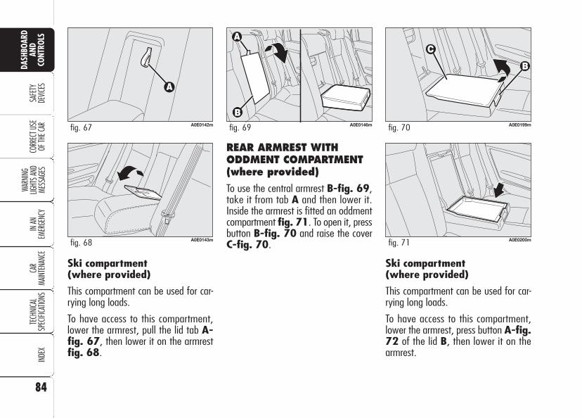
84
SAFE
TYDE
VICES
WARN
ING
LIGHT
S AN
D ME
SSAG
ESIN
AN
EMER
GENC
YCA
RMA
INTE
NANC
ETE
CHNI
CAL
SPEC
IFICA
TIONS
INDE
XCO
RREC
T USE
OF
THE C
AR
DASH
BOAR
DAN
DCO
NTRO
LS
REAR ARMREST WITHODDMENT COMPARTMENT(where provided)
To use the central armrest B-fig. 69,take it from tab A and then lower it.Inside the armrest is fitted an oddmentcompartment fig. 71. To open it, pressbutton B-fig. 70 and raise the coverC-fig. 70.
A0E0146mfig. 69
A0E0200mfig. 71
A0E0199mfig. 70
Ski compartment (where provided)
This compartment can be used for car-rying long loads.
To have access to this compartment,lower the armrest, press button A-fig.72 of the lid B, then lower it on thearmrest.
Ski compartment (where provided)
This compartment can be used for car-rying long loads.
To have access to this compartment,lower the armrest, pull the lid tab A-fig. 67, then lower it on the armrestfig. 68.
A0E0142mfig. 67
A0E0143mfig. 68

85
SAFE
TYDE
VICES
WARN
ING
LIGHT
S AN
D ME
SSAG
ES
IN AN
EM
ERGE
NCY
CAR
MAIN
TENA
NCE
TECH
NICA
LSP
ECIFI
CATIO
NSIN
DEX
CORR
ECT U
SE
OF TH
E CAR
DASH
BOAR
DAN
DCO
NTRO
LS
To open the lid B, switch A-fig. 73(accessible from the boot) shall be setin vertical position (horizontal positionÁ = compartment locked).
A0E0148mfig. 73
A0E0147mfig. 72
GLOVE COMPARTMENT
To open the glove compartment use leverA-fig. 74. When the glove compart-ment is opened, the internal courtesy lightturns on. Leaving inadvertently open theglove compartment, this light will turn offautomatically after a few minutes. Thefolding top is also provided with a recessfor a pen or a pencil.
A0E0149mfig. 74
Do not travel with theglove compartment open;it could harm the passen-
ger in the event of an accident.
CIGAR LIGHTER
Front cigar lighter(optional for versions/markets where applicable)
It is located on the central console, nearthe handbrake lever. To use the cigarlighter, raise cover A-fig. 75 as shownby the arrow.
A0E0031mfig. 75

86
SAFE
TYDE
VICES
WARN
ING
LIGHT
S AN
D ME
SSAG
ESIN
AN
EMER
GENC
YCA
RMA
INTE
NANC
ETE
CHNI
CAL
SPEC
IFICA
TIONS
INDE
XCO
RREC
T USE
OF
THE C
AR
DASH
BOAR
DAN
DCO
NTRO
LS
Press button B-fig. 76 to switch onthe cigar lighter with key fitted into ig-nition device.
IMPORTANT Always check that the cig-ar lighter has turned off.
IMPORTANT The cigar lighter getsvery hot. Handle it with care and makesure that it is not used by children: dan-ger of fire and/or burns.
IMPORTANT Do not plug electric ac-cessories with power exceeding 100Wto the front cigar lighter seat.
A0E0152mfig. 76
Rear cigar lighter (optional for versions/markets where applicable)
It is located on the central console be-tween the seats (see fig. 77).
IMPORTANT Do not plug electric ac-cessories with power exceeding 140Wto the rear cigar lighter seat.
IMPORTANT Oversize plugs coulddamage the cigar lighter outlet tabs.
Do not plug electric ac-cessories with absorptionexceeding the max. spec-
ified value. Prolonged current ab-sorption could drain the batteryand impair next engine start up.OFF
O
I
AUTO
AUTO
A0E0068mfig. 77
IMPORTANT To safeguard the light-ing life of certain internal devices (e.g.:cigar lighter ring and ashtray), whenswitching on the external lights, thesedevices will switch on according to thepassenger's compartment brightness:with enough daylight these devices willnot switch on. On the contrary they willswitch on with poor daylight.

87
SAFE
TYDE
VICES
WARN
ING
LIGHT
S AN
D ME
SSAG
ES
IN AN
EM
ERGE
NCY
CAR
MAIN
TENA
NCE
TECH
NICA
LSP
ECIFI
CATIO
NSIN
DEX
CORR
ECT U
SE
OF TH
E CAR
DASH
BOAR
DAN
DCO
NTRO
LS
GLASS/CAN HOLDER fig. 80
It is located on the central console, nearthe handbrake lever. To use it lift coverA-fig. 75.
EYEGLASSES HOLDER (where provided)
It is located near the front ceiling light.To use it, press lid A-fig. 81.
ASHTRAY (optional for versions/markets where applicable)
Front ashtray
It is located on the central console, nearthe handbrake lever.
To use the cigar lighter, raise cover A-fig. 78 and open lid B.
Front ashtray is removable: to removeit, pull it upwards.
IMPORTANT Do not use the ashtrayas paper bin: it could set on fire on con-tact with cigarette stubs.
A0E0153mfig. 79 A0E0101mfig. 80
A0E0156mfig. 81
A0E0140mfig. 78
Rear ashtray
It is located on the central console, be-tween front seats. To use the ashtray,lift lid A-fig. 79 as shown by the ar-row.
Rear ashtray is removable: to remove it,press on the central part and pull it up-wards.
IMPORTANT Do not use the ashtrayas paper bin: it could set on fire on con-tact with cigarette stubs.

88
SAFE
TYDE
VICES
WARN
ING
LIGHT
S AN
D ME
SSAG
ESIN
AN
EMER
GENC
YCA
RMA
INTE
NANC
ETE
CHNI
CAL
SPEC
IFICA
TIONS
INDE
XCO
RREC
T USE
OF
THE C
AR
DASH
BOAR
DAN
DCO
NTRO
LS
ODDMENTS COMPARTMENTS(where provided) fig. 84
They are located on the central consolebetween the front seats.
SUN VISORS
These are positioned to the sides of therear-view mirror. They can swing to thesides and up or down.
On certain versions, sun visors are fittedon the back with a courtesy mirror anda light which enables to use the mirroralso with poor sunlight.
A0E0154mfig. 84 A0E0102mfig. 85
To use the mirror open cover A-fig.85.
Mirror lights will turn on automaticallywhen lifting the cover and they will turnoff when lowering it or few minutes af-ter removing the electronic key from theignition device.
SUN VISORS (where provided)
Certain versions are provided with sun-visors behind the rear seats.
To use it, take the tab A-fig. 82, pull itforwards and secure it to the hooks set onthe top of the car roof (see fig. 83).
A0E0197mfig. 82
A0E0198mfig. 83
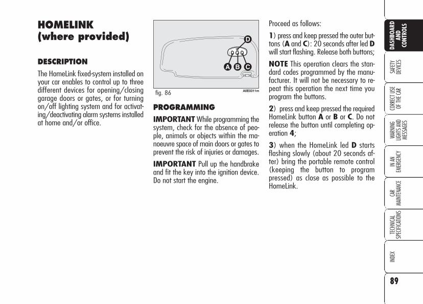
PROGRAMMING
IMPORTANT While programming thesystem, check for the absence of peo-ple, animals or objects within the ma-noeuvre space of main doors or gates toprevent the risk of injuries or damages.
IMPORTANT Pull up the handbrakeand fit the key into the ignition device.Do not start the engine.
Proceed as follows:
1) press and keep pressed the outer but-tons (A and C): 20 seconds after led Dwill start flashing. Release both buttons;
NOTE This operation clears the stan-dard codes programmed by the manu-facturer. It will not be necessary to re-peat this operation the next time youprogram the buttons.
2) press and keep pressed the requiredHomeLink button A or B or C. Do notrelease the button until completing op-eration 4;
3) when the HomeLink led D startsflashing slowly (about 20 seconds af-ter) bring the portable remote control(keeping the button to programpressed) as close as possible to theHomeLink.
89
SAFE
TYDE
VICES
WARN
ING
LIGHT
S AN
D ME
SSAG
ES
IN AN
EM
ERGE
NCY
CAR
MAIN
TENA
NCE
TECH
NICA
LSP
ECIFI
CATIO
NSIN
DEX
CORR
ECT U
SE
OF TH
E CAR
DASH
BOAR
DAN
DCO
NTRO
LSHOMELINK(where provided)
DESCRIPTION
The HomeLink fixed-system installed onyour car enables to control up to threedifferent devices for opening/closinggarage doors or gates, or for turningon/off lighting system and for activat-ing/deactivating alarm systems installedat home and/or office.
A0E0311mfig. 86
HOW TO USE THEHOMELINK SYSTEM
The HomeLink remote control activatesthe operation of the garage door mo-tor or gate motor exactly as the portableremote control. The car shall be withinthe range of the motor and the key shallbe fitted into the ignition device.
Press the programmed button (A or Bor C). During signal transmission the ledD will stay on and the set system(garage door, gate, etc.) will obey.
If the HomeLink system set as describedabove does not work, this may be dueto the fact the original portable remotecontrol has an alternate code (see para-graph "Synchronising alternate codes").
It is however always possible to use theoriginal portable remote control to op-erate the system (garage door, gate,etc.).
SYNCHRONISINGALTERNATE CODES
To ascertain whether your garage doormotor or gate motor is provided with analternate code, proceed as follows:
consult the owner handbook providedby the garage door motor's or gate mo-tor's manufacturer;
the portable remote control seems tohave programmed HomeLink; HomeLinkhowever is not up to open or to closethe garage door or the gate;
press and keep pressed the programmedbutton (A or B or C).
With an alternate code system, the ledD blinks fast for short and then it stayson glowing steadily for two seconds.This sequence is repeated for 20 sec-onds.
The distance required between theportable remote control and the Home-Link depends on the system to be pro-grammed (type of frequency of maindoor, gate or other system).
If D does not start to flash quickly tryagain changing the distance betweenHomeLink and portable remote control(move them away slightly). If 20 sec-onds later the led is still flashing slow-ing, repeat the operation changing againthe distance between Homelink and re-mote control.
4) the HomeLink led D will start blink-ing, first slowly and then quickly. Whenit starts flashing quickly, release bothbuttons (HomeLink and portable remotecontrol).
90
SAFE
TYDE
VICES
WARN
ING
LIGHT
S AN
D ME
SSAG
ESIN
AN
EMER
GENC
YCA
RMA
INTE
NANC
ETE
CHNI
CAL
SPEC
IFICA
TIONS
INDE
XCO
RREC
T USE
OF
THE C
AR
DASH
BOAR
DAN
DCO
NTRO
LS

Proceed as follows:
❒ find the set-up button on the upperside of the garage door/gate motor.Colour and position may vary ac-cording to the manufacturer (consultthe motor handbook);
❒ press the motor set-up button (thisaction will usually turn up the "set-up" pilot light). After operation 2,start to perform operation 3 within30 seconds;
❒ press the programmed button (A orB or C) and release it. Press againthe programmed button and then re-lease it to end the operation. Certainmotors could require to repeat onceagain the operation for concludingthe setting.
Now the motor should be up to recog-nise the signal transmitted by HomeLinkand therefore to open/close the garagedoor or the gate.
RE-PROGRAMMING ONESINGLE BUTTON
It is possible to programme another orig-inal portable remote control on oneHomeLink button already programmed.Previous programming will be cancelled.
IMPORTANT While programming thesystem, check for the absence of peo-ple, animals or objects within the ma-noeuvre space of main doors or gates toprevent the risk of injuries or damages.
IMPORTANT Pull up the handbrakeand fit the key into the ignition device.Do not start the engine.
Proceed as follows:
1) press and keep pressed the requiredHomeLink button A or B or C. Do notrelease the button until completing op-eration 3;
2) when the HomeLink led D startsflashing slowly (about 20 seconds af-ter) bring the portable remote control(keeping the button to programpressed) as close as possible to theHomeLink.
HomeLink can only work if the pro-grammed alternate code is synchronisedwith the system of the device (garagedoor, gate, etc.).
IMPORTANT While synchronising thesystem, check for the absence of peo-ple, animals or objects within the ma-noeuvre space of main doors or gates toprevent the risk of injuries or damages.
IMPORTANT The car shall be withinthe range of the motor. Pull up the hand-brake and fit the key into the ignitiondevice. Do not start the engine.
91
SAFE
TYDE
VICES
WARN
ING
LIGHT
S AN
D ME
SSAG
ES
IN AN
EM
ERGE
NCY
CAR
MAIN
TENA
NCE
TECH
NICA
LSP
ECIFI
CATIO
NSIN
DEX
CORR
ECT U
SE
OF TH
E CAR
DASH
BOAR
DAN
DCO
NTRO
LS

CLEARING THEPROGRAMMED BUTTONS
You are recommended to clear theHomeLink programming before sellingthe car.
Programming is cleared on all the threebuttons at the same time.
Proceed as follows:
❒ press and keep pressed the outerbuttons (A and C): 20 seconds af-ter led D will start flashing.
❒ Release both buttons.
TECHNICAL DATA FOR THEASSISTANCE SERVICE
If after following the previous instruc-tions you are still unable to set theHomeLink system, contact the Assis-tance Service (HomeLink toll free num-ber 00800046635465) and commu-nicate the following data:
❒ make and model of your car, in-cluding the date of manufacture andthe country where you bought it;
❒ make, model, date of manufactureand operating frequency of the orig-inal portable remote control (ifknown).
IMPORTANT Certain phone carriersdo not permit the use of the toll-freenumber. It is therefore required to dialthe alternative pay-number, +49 6838907-277 (dialling this number will startan international call).
The distance required between theportable remote control and the Home-Link depends on the system to be pro-grammed (type of frequency of maindoor, gate or other system).
If D does not start to flash quickly tryagain changing the distance betweenHomeLink and portable remote control(move them away slightly). If 20 sec-onds later the led is still flashing slow-ing, repeat the operation changing againthe distance between Homelink and re-mote control.
3) the HomeLink led D will start blink-ing, first slowly and then quickly. Whenit starts flashing quickly, release bothbuttons (HomeLink and portable remotecontrol).
In this way the system previously pro-grammed on HomeLink is cleared andthe new system is ready for use. Thisoperation has no effect on the other twoHomeLink buttons.
92
SAFE
TYDE
VICES
WARN
ING
LIGHT
S AN
D ME
SSAG
ESIN
AN
EMER
GENC
YCA
RMA
INTE
NANC
ETE
CHNI
CAL
SPEC
IFICA
TIONS
INDE
XCO
RREC
T USE
OF
THE C
AR
DASH
BOAR
DAN
DCO
NTRO
LS

93
SAFE
TYDE
VICES
WARN
ING
LIGHT
S AN
D ME
SSAG
ES
IN AN
EM
ERGE
NCY
CAR
MAIN
TENA
NCE
TECH
NICA
LSP
ECIFI
CATIO
NSIN
DEX
CORR
ECT U
SE
OF TH
E CAR
DASH
BOAR
DAN
DCO
NTRO
LSSUNROOF(where provided)
The sunroof consists of a moving panesliding horizontally and retractable.
When closed it enables sunlight to getinto the passenger compartment, where-as when open it enables wide openingof the whole glass sunroof surface.
The sunroof is provided with manually-operated sun curtain with handle and airvents.
Sunroof can only be operated when thekey is fitted into the ignition device.
Do not open the sunroofif there is snow or ice onit: it could be damaged.
IMPORTANT Top comfort positionwith sunroof open is obtained by turn-ing selector A-fig. 87 to position.
Operating the selector it is possible toopen/close the sunroof in one of the fol-lowing cases:
❒ fitting the electronic key into the ig-nition device;
❒ in the first 2 minutes after removingthe key from the ignition device or upto door opening.
Opening from outside the car
Press the electronic key button Ë forover 2 seconds.
When leaving the car,the ignition key should
be removed to prevent thesunroof from being operatedinadvertently and harminganyone remaining in the car.Improper use of the sunroofcan be dangerous. Before andduring its operation ensurethat any passengers are not atrisk from the moving roof ei-ther by personal objects get-ting caught in the mechanismor by being injured by it di-rectly.
WARNING
C
A0E0238mfig. 87
SUNROOF OPENING
Opening from inside the car
Turn selector A-fig. 87, as shown by thearrow. The sunroof will stop in position assoon as the selector is released.
The movement of the roof may be inter-rupted and restarted by means of slightpressure on selector A.
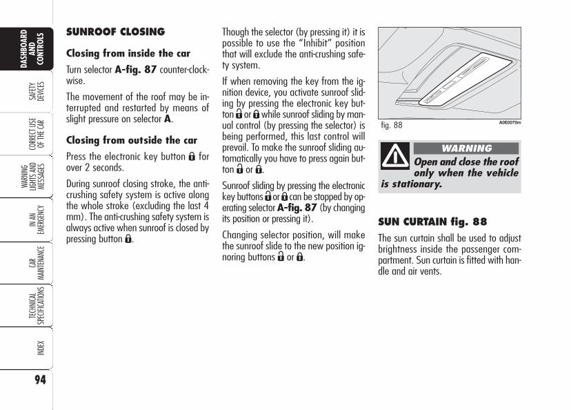
94
SAFE
TYDE
VICES
WARN
ING
LIGHT
S AN
D ME
SSAG
ESIN
AN
EMER
GENC
YCA
RMA
INTE
NANC
ETE
CHNI
CAL
SPEC
IFICA
TIONS
INDE
XCO
RREC
T USE
OF
THE C
AR
DASH
BOAR
DAN
DCO
NTRO
LS
SUN CURTAIN fig. 88
The sun curtain shall be used to adjustbrightness inside the passenger com-partment. Sun curtain is fitted with han-dle and air vents.
Though the selector (by pressing it) it ispossible to use the “Inhibit” positionthat will exclude the anti-crushing safe-ty system.
If when removing the key from the ig-nition device, you activate sunroof slid-ing by pressing the electronic key but-ton Ë or Áwhile sunroof sliding by man-ual control (by pressing the selector) isbeing performed, this last control willprevail. To make the sunroof sliding au-tomatically you have to press again but-ton Ë or Á.
Sunroof sliding by pressing the electronickey buttons ËorÁ can be stopped by op-erating selector A-fig. 87 (by changingits position or pressing it).
Changing selector position, will makethe sunroof slide to the new position ig-noring buttons Ë or Á.
Open and close the roofonly when the vehicle
is stationary.
WARNING
A0E0070mfig. 88
SUNROOF CLOSING
Closing from inside the car
Turn selector A-fig. 87 counter-clock-wise.
The movement of the roof may be in-terrupted and restarted by means ofslight pressure on selector A.
Closing from outside the car
Press the electronic key button Á forover 2 seconds.
During sunroof closing stroke, the anti-crushing safety system is active alongthe whole stroke (excluding the last 4mm). The anti-crushing safety system isalways active when sunroof is closed bypressing button Á.

95
SAFE
TYDE
VICES
WARN
ING
LIGHT
S AN
D ME
SSAG
ES
IN AN
EM
ERGE
NCY
CAR
MAIN
TENA
NCE
TECH
NICA
LSP
ECIFI
CATIO
NSIN
DEX
CORR
ECT U
SE
OF TH
E CAR
DASH
BOAR
DAN
DCO
NTRO
LSANTI-CRUSHING SAFETYSYSTEM
The anti-crushing safety system fitted onthe front curtain outline is active duringhorizontal closing (front edge) and ver-tical closing of the panel (rear edge) andit will cut in when it finds an obstacle(e.g.: finger, hand, etc …), thus guar-anteeing sunroof reversal for a short sec-tion.
When an obstacle is found, sunroofstroke is stopped immediately and itsstroke is reversed to the preset position:
❒ during horizontal closing it is activealong the whole stroke of the sunroofand when it finds an obstacle on thefront side of the pane it guaranteesa 10 cm stroke reversal;
❒ during vertical closing it is activealong the whole stroke of the sunroofand when it finds an obstacle on therear side of the pane it guaranteesstroke reversal.
EMERGENCY OPERATION
In a emergency or during servicing (with-out power supply), the sunroof can beoperated manually; proceed as follows:
❒ press the light notches to release theclips and remove the front ceiling lightA-fig. 89.
❒ fit the setscrew wrench into the prop-er slot B;
❒ turn the key to open or to close (ac-cording to rotation direction) the sun-roof.
SUNROOF INITIALISATION PROCEDURE
After disconnecting the battery or failingthe protection fuse, the sunroof shall be“initialised” again, proceed as follows:
❒ turn selector fully leftwards (counter-clokwise);
❒ press and keep pressed selector untilsunroof locking;
❒ release selector;
❒ press selector again within 3 seconds,and keep it pressed;
❒ a few seconds after the sunroof willmove automatically (during this stagekeep on pressing the knob);
❒ initialisation will end when the sun-roof stops. Release selector.
A0E0187mfig. 89
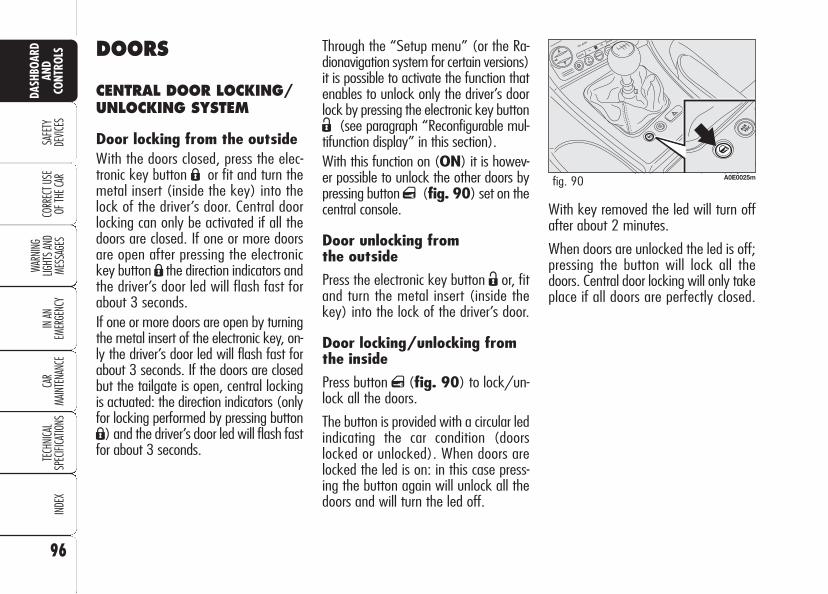
96
SAFE
TYDE
VICES
WARN
ING
LIGHT
S AN
D ME
SSAG
ESIN
AN
EMER
GENC
YCA
RMA
INTE
NANC
ETE
CHNI
CAL
SPEC
IFICA
TIONS
INDE
XCO
RREC
T USE
OF
THE C
AR
DASH
BOAR
DAN
DCO
NTRO
LS
With key removed the led will turn offafter about 2 minutes.
When doors are unlocked the led is off;pressing the button will lock all thedoors. Central door locking will only takeplace if all doors are perfectly closed.
DOORS
CENTRAL DOOR LOCKING/UNLOCKING SYSTEM
Door locking from the outsideWith the doors closed, press the elec-tronic key button Á or fit and turn themetal insert (inside the key) into thelock of the driver’s door. Central doorlocking can only be activated if all thedoors are closed. If one or more doorsare open after pressing the electronickey button Á the direction indicators andthe driver’s door led will flash fast forabout 3 seconds.If one or more doors are open by turningthe metal insert of the electronic key, on-ly the driver’s door led will flash fast forabout 3 seconds. If the doors are closedbut the tailgate is open, central lockingis actuated: the direction indicators (onlyfor locking performed by pressing buttonÁ) and the driver’s door led will flash fastfor about 3 seconds.
A0E0025mfig. 90
Through the “Setup menu” (or the Ra-dionavigation system for certain versions)it is possible to activate the function thatenables to unlock only the driver’s doorlock by pressing the electronic key buttonË (see paragraph “Reconfigurable mul-tifunction display” in this section).With this function on (ON) it is howev-er possible to unlock the other doors bypressing button q (fig. 90) set on thecentral console.
Door unlocking from the outside
Press the electronic key button Ë or, fitand turn the metal insert (inside thekey) into the lock of the driver’s door.
Door locking/unlocking fromthe inside
Press button q (fig. 90) to lock/un-lock all the doors.
The button is provided with a circular ledindicating the car condition (doorslocked or unlocked). When doors arelocked the led is on: in this case press-ing the button again will unlock all thedoors and will turn the led off.

97
SAFE
TYDE
VICES
WARN
ING
LIGHT
S AN
D ME
SSAG
ES
IN AN
EM
ERGE
NCY
CAR
MAIN
TENA
NCE
TECH
NICA
LSP
ECIFI
CATIO
NSIN
DEX
CORR
ECT U
SE
OF TH
E CAR
DASH
BOAR
DAN
DCO
NTRO
LS
CHILD LOCK
Rear doors are fitted with a locking de-vice fig. 91 that inhibits door open-ing from the inside.
This device can be engaged/disengaged(by the metal insert of the key) onlywith doors open:
❒ position 1: engaged (door locked);
❒ position 2: disengaged (door canbe opened from the inside).
IMPORTANT Each device acts onlyon the relevant door.
IMPORTANT Always use this devicewhen transporting children.
IMPORTANT After engaging the childlock on both rear doors, check for prop-er engagement by trying to open a reardoor with the internal handle.
Buttonq is disabled after door lockingcarried out by operating the remote con-trol, the driver's door revolving plug, orby automatic door locking after about2.5 minutes and it will be enabled againafter door unlocking carried out by press-ing the key button Ë, by turning themetal insert of the key into the driver'sdoor lock or by fitting the key into theignition device.
IMPORTANT With central locking sys-tem on, pulling the internal door handlewill unlock all the doors. Lacking pow-er (blown fuse, battery disconnected,etc.) it is however possible to lock thedoors manually.
A0E0155mfig. 91

Doorknobs can be realigned (only afterrecharging the battery) as follows:
❒ pressing the electronic key button Ë;
❒ pressing door locking/unlocking but-tonq;
❒ opening with the key in front door re-volving plug;
❒ pulling internal door handle.
IMPORTANT As concerns rear doors,with child lock device on and the previ-ously described locking active, operat-ing the internal door handle will notopen the door but will only realign door-knobs; to open the door pull the exter-nal door handle. Emergency locking willnot disable central door locking/un-locking button q.
IMPORTANT After disconnecting thebattery or failing the protection fuse, thedoor locking/unlocking mechanism shallbe “initialised” again, proceed as fol-lows:
❒ lock the doors;
❒ press the remote control button Á orthe button q on the central console;
❒ press the remote control button Ë orthe button q on the central console.
DOOR LOCKING WITH RUNDOWN BATTERY
If the car battery is run down, to lockthe doors proceed as described in thefollowing points.
Right front door
Proceed as follows:
❒ remove the protection plug on thedoor;
❒ fit the electronic key metal insert in-to A-fig. 92;
❒ turn the key clockwise (counter-clock-wise for right-hand drive versions);
❒ remove the key from A-fig. 92 andthen efit the plug on the door.
98
SAFE
TYDE
VICES
WARN
ING
LIGHT
S AN
D ME
SSAG
ESIN
AN
EMER
GENC
YCA
RMA
INTE
NANC
ETE
CHNI
CAL
SPEC
IFICA
TIONS
INDE
XCO
RREC
T USE
OF
THE C
AR
DASH
BOAR
DAN
DCO
NTRO
LS
A0E0237mfig. 92

99
SAFE
TYDE
VICES
WARN
ING
LIGHT
S AN
D ME
SSAG
ES
IN AN
EM
ERGE
NCY
CAR
MAIN
TENA
NCE
TECH
NICA
LSP
ECIFI
CATIO
NSIN
DEX
CORR
ECT U
SE
OF TH
E CAR
DASH
BOAR
DAN
DCO
NTRO
LSIn this case it is necessary to carry outsystem restore procedure as follows:
❒ open the windows;
or
❒ remove and then refit the key into theignition device.
If no malfunction is present, the windowreturns to its normal operation automat-ically. In the event of a failure see section“Warning lights and messages”.
Windows and sunroofopening/closing by theelectronic key (where provided)
By the metal insert of the key
On all versions:
❒ turning clockwise the metal insert ofthe key into the driver's door re-volving plug will open all the win-dows and the sunroof (where pro-vided) at the same time.
❒ turning counterclockwise the metalinsert of the key into the driver'sdoor revolving plug will close all thewindows and the sunroof (whereprovided) at the same time.
By remote control
On all versions, keep button Ë pressedfor over 2 seconds to open all the win-dows and the sunroof (where provided)at the same time.
On versions provided with 4 power win-dow, keep button Á pressed for over 2seconds to close all the windows andthe sunroof (where provided) at thesame time.
POWER WINDOWS
Versions with 2 front power windowsare fitted with automatic window open-ing/closing only on the driver’s side.
Versions with 4 power windows are fit-ted with automatic window opening/closing on all doors. For certain ver-sions/markets the electric windowsmay have a safety system with anti-crushing gaskets that identify any ob-stacles present when the window is clos-ing. If this happens, the system imme-diately interrupts and changes the di-rection of the window movement.
This system is particularly useful whenchildren operate the windows inadver-tently and make it possible to close/open (where provided) the windows us-ing the remote control when leaving thecar.
IMPORTANT In the event the anti-crushing function is activated 5 times inonly 1 minute or in the event of a fail-ure, the system will automatically enterthe “recovery” mode (self-protection).This condition is pointed out by the factthat, in the closing stroke, the windowsgoes up in jerks.
The system complieswith the forthcomingStandard 2000/4/ EC
concerning the safety of pas-sengers leaning out of the pas-senger compartment.

100
SAFE
TYDE
VICES
WARN
ING
LIGHT
S AN
D ME
SSAG
ESIN
AN
EMER
GENC
YCA
RMA
INTE
NANC
ETE
CHNI
CAL
SPEC
IFICA
TIONS
INDE
XCO
RREC
T USE
OF
THE C
AR
DASH
BOAR
DAN
DCO
NTRO
LS C (where provided) – rear left windowopening/closing; “automatic continu-ous” mode operation during windowopening/closing;
D (where provided) – rear right win-dow opening/closing; “automatic con-tinuous” mode operation just during win-dow opening;
E (where provided) – rear power win-dow enabling/disabling controls (whenrear power window controls are dis-abled, the led on button E will turn onand disabled controls will turn off).
Press buttons A, B, C or D to open/close the required window.
Pressing briefly one of the buttons thewindow “jerks” whereas a prolongedpressing makes the window opening orclosing in “automatic continuous”mode.
Pressing button A, B, C or D again willstop the window in the required posi-tion.
Front passenger door/rear doors
Front passenger door and, on certainversions, rear doors are fitted with but-ton panels controlling opening/closingof the corresponding window.
CONTROLS
Driver side
On the driver’s door panel are set thebuttons fig. 93 for controlling, withelectronic key fitted into the ignition de-vice:
A – front left window opening/closing;window opening or closing in “auto-matic continuous” mode;
B – front right window opening/clos-ing; window opening or closing in “au-tomatic continuous” mode (only ver-sions with 4 power windows);
A0E0051mfig. 93
Improper use of thepower windows can bedangerous. Before and
during its operation ensure thatany passengers are not at riskfrom the moving glass either bypersonal objects getting caughtin the mechanism or by being in-jured by it directly. Always re-move the ignition key whengetting out of the car to preventthe power windows being op-erated accidentally and consti-tuting a danger to the passen-gers in the car.

101
SAFE
TYDE
VICES
WARN
ING
LIGHT
S AN
D ME
SSAG
ES
IN AN
EM
ERGE
NCY
CAR
MAIN
TENA
NCE
TECH
NICA
LSP
ECIFI
CATIO
NSIN
DEX
CORR
ECT U
SE
OF TH
E CAR
DASH
BOAR
DAN
DCO
NTRO
LS
On certain versions, improper bootclosing is indicated by the instrumentpanel warning light ´, whereas onother versions the symbol R and amessage are displayed (see section“Warning lights and messages”).
OPENING FROM THE INSIDE
Press button A-fig. 94 set on thefront ceiling light.
Button A-fig. 94 is disabled whenlocking the doors by:
❒ pressing the electronic key buttonÁ;
❒ turning the metal insert of the keyinto the driver's door lock;
❒ automatic locking of the doorsafter about 2.5 minutes.
Tailgate opening is facilitated by theside gas shock springs.
Opening the boot its internal light willturn on and it will turn off automati-cally when re-closing the tailgate.Leaving the tailgate inadvertentlyopen, the light will turn off automati-cally after a few minutes.
BOOT
The boot lock is electric and it is dis-abled when the car is running.
Through the “Setup menu” (or theRadionavigation system for certainversions) boot opening can be set byselecting the option “Indep. boot”(see paragraph “Reconfigurable multi-function display” in this section):when this function is on, the boot canonly be opened by pressing the elec-tronic key button `, thus inhibit-ing the boot opening button on theceiling light A-fig. 94.
A0E0096mfig. 94

102
SAFE
TYDE
VICES
WARN
ING
LIGHT
S AN
D ME
SSAG
ESIN
AN
EMER
GENC
YCA
RMA
INTE
NANC
ETE
CHNI
CAL
SPEC
IFICA
TIONS
INDE
XCO
RREC
T USE
OF
THE C
AR
DASH
BOAR
DAN
DCO
NTRO
LS OPENING BY REMOTECONTROL
Press the electronic key button `.Opening is indicated by double flashingof direction indicators.
Opening the boot with alarm (whereprovided) on will cause the following:
❒ volumetric protection deactivation;
❒ anti-raising protection deactivation;
❒ tailgate monitoring sensor.
Re-closing the tailgate will restore all theabove functions and direction indicatorswill turn on for about 1 second.
Emergency opening of theboot from the passengercompartment (foreseen onlyon the 3-volume saloonversion)
If the battery is disconnected, the bootcan be opened by pulling the lever A-fig. 95 set under the rear left seat.
Refit the handle under the cushion afterusing it.
A0E0228mfig. 95
IMPORTANT After disconnecting thebattery or failing the protection fuse, thetailgate locking/unlocking mechanismshall be “initialised” again, proceed asfollows:
❒ lock the doors and the tailgate;
❒ press the remote control button Á orthe button q on the central console;
❒ press the remote control button Ë orthe button q on the central console.

103
SAFE
TYDE
VICES
WARN
ING
LIGHT
S AN
D ME
SSAG
ES
IN AN
EM
ERGE
NCY
CAR
MAIN
TENA
NCE
TECH
NICA
LSP
ECIFI
CATIO
NSIN
DEX
CORR
ECT U
SE
OF TH
E CAR
DASH
BOAR
DAN
DCO
NTRO
LSTAILGATE CLOSING
Lower the tailgate pressing the lock un-til hearing the locking click.
IMPORTANT If the option for ”Indep.boot” is on, before closing the boot,check whether you have with you theignition key since the boot will be lockedautomatically.
The addition of objects(speakers, spoilers, etc.)on the rear shelf or boot
lid, except those envisaged bythe manufacturer, may preventthe gas filled struts at the sidesof the boot from working prop-erly.
When using the boot,make sure the loads do
not exceed the permittedweight (see “Technical specifi-cations” chapter). Also makesure the items in the boot arearranged properly to preventthem being thrown forwardsand injuring passengers shouldyou brake sharply.
WARNING
Never travel with ob-jects on the rear shelf
to prevent them being thrownforwards and injuring passen-gers in case of accident orsharp braking.
WARNING
EXTENDING THE BOOT(where provided)
To extend the boot proceed as follows:
❒ remove rear head restraints;
❒ turn head restraints by 180° and fitthem into their seat;
❒ move aside the seat belt, check thatit is not twisted;
❒ lift seat back lever A-fig. 96 andtilt the seat back forward. Lever rais-ing is indicated by a “red band” B.
A0E0085mfig. 96

104
SAFE
TYDE
VICES
WARN
ING
LIGHT
S AN
D ME
SSAG
ESIN
AN
EMER
GENC
YCA
RMA
INTE
NANC
ETE
CHNI
CAL
SPEC
IFICA
TIONS
INDE
XCO
RREC
T USE
OF
THE C
AR
DASH
BOAR
DAN
DCO
NTRO
LS
ANCHORING THE LOAD
The boot houses 4 hooks A-fig. 97for anchoring ropes in order to guaran-tee perfect load anchoring.
A0E0131mfig. 97
A heavy load that hasnot been secured may
cause serious harm.
WARNING
If you want to carryreserve fuel in a can,
follow law regulations, onlyusing a certified can, suitablyfastened to the load securingeyelets. Even in this way therisk of fire is increased in thecase of an accident.
WARNINGTO RETURN THE REAR SEATBACK TO ITS ORIGINALPOSITION
Move aside the seat belts, check thatthey are not twisted.
Raise the seat backrests and push themback until hearing the locking click ofboth retainers; the “red band” B asidethe levers A shall no longer be visible.The “red band” B actually indicates thatthe backrest is not properly secured.
IMPORTANT Make sure the head re-straints are properly positioned.
Make sure the backrestis properly secured at
both sides (“red bands” B-fig.96 not visible) to prevent itmoves forward in the event ofsharp braking causing injuriesto passengers.
WARNING

105
SAFE
TYDE
VICES
WARN
ING
LIGHT
S AN
D ME
SSAG
ES
IN AN
EM
ERGE
NCY
CAR
MAIN
TENA
NCE
TECH
NICA
LSP
ECIFI
CATIO
NSIN
DEX
CORR
ECT U
SE
OF TH
E CAR
DASH
BOAR
DAN
DCO
NTRO
LSImproper bonnet closing is indicated (oncertain versions) by the instrument pan-el warning light ́ (where provided), orby symbol S and a message on thedisplay (see section “Warning lights andmessages”).
IMPORTANT Always check that thebonnet is closed properly to avoid itsopening while the car is travelling.
BONNET
TO OPEN THE BONNET
Proceed as follows:
❒ pull lever A-fig. 98 until hearingthe releasing click;
❒ pull lever B-fig. 99 and raise thebonnet keeping the lever pulled
IMPORTANT Bonnet raising is aidedby two gas springs. Do not tamper withthese springs and guide the bonnetwhile raising it.
IMPORTANT Before opening the bon-net, check that windscreen wiper armsare not lifted from the windscreen.
A0E0122mfig. 98
A0E0158mfig. 99
TO CLOSE THE BONNET
Lower the bonnet at approx. 20 cen-timetres from the engine compartmentand then let it drop, ensuring that it isfully closed and not just held in positionby the safety catch. If the bonnet doesnot close properly, do not push it downbut open it again and repeat the aboveprocedure.
Carry out operationsonly when the car is
stationary.
WARNING
For safety reasons thebonnet must be closed
properly to avoid its openingwhile the car is travelling.Therefore, always check it isproperly closed and the catchengaged. Should you noticethat the catch is not perfectlyengaged when travelling, stopthe car immediately and closethe bonnet.
WARNING

106
SAFE
TYDE
VICES
WARN
ING
LIGHT
S AN
D ME
SSAG
ESIN
AN
EMER
GENC
YCA
RMA
INTE
NANC
ETE
CHNI
CAL
SPEC
IFICA
TIONS
INDE
XCO
RREC
T USE
OF
THE C
AR
DASH
BOAR
DAN
DCO
NTRO
LS ROOF RACK/SKI RACK
The car is preset for mounting roofracks/ski racks.
Front hooks are in points A-fig. 100.
Rear hooks are in points B. A0E0097mfig. 100
HEADLIGHTS
ADJUSTING THE HEADLIGHTBEAM
Proper adjustment of the headlightbeams is of vital importance for yoursafety and comfort and also for the oth-er road users. To ensure you and otherdrivers have the best visibility conditionswhen travelling with the headlights on,the headlights must be set properly. Con-tact Alfa Romeo Authorized Services tohave the headlights properly adjusted.
HEADLIGHT AIMING DEVICE
It works with the key fitted into the ig-nition device and dipped beams on.
When the car is loaded, it slopes back-wards. This means that the headlightbeam rises. In this case, it is necessaryto return it to the correct position.
Distribute the load even-ly and when driving, bearin mind the increased
sensitivity to side wind.
IMPORTANT After few kilometers,check that fastening screws are firmlytightened.
IMPORTANT Never exceed the max.permissible loads (see section “”Tech-nical specifications”).
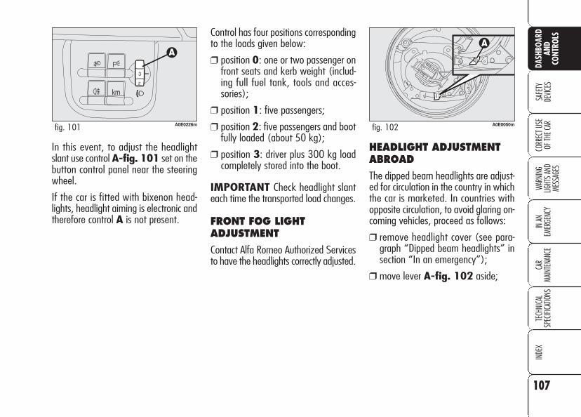
107
SAFE
TYDE
VICES
WARN
ING
LIGHT
S AN
D ME
SSAG
ES
IN AN
EM
ERGE
NCY
CAR
MAIN
TENA
NCE
TECH
NICA
LSP
ECIFI
CATIO
NSIN
DEX
CORR
ECT U
SE
OF TH
E CAR
DASH
BOAR
DAN
DCO
NTRO
LS
In this event, to adjust the headlightslant use control A-fig. 101 set on thebutton control panel near the steeringwheel.
If the car is fitted with bixenon head-lights, headlight aiming is electronic andtherefore control A is not present.
Control has four positions correspondingto the loads given below:
❒ position 0: one or two passenger onfront seats and kerb weight (includ-ing full fuel tank, tools and acces-sories);
❒ position 1: five passengers;
❒ position 2: five passengers and bootfully loaded (about 50 kg);
❒ position 3: driver plus 300 kg loadcompletely stored into the boot.
IMPORTANT Check headlight slanteach time the transported load changes.
FRONT FOG LIGHTADJUSTMENT
Contact Alfa Romeo Authorized Servicesto have the headlights correctly adjusted.
A0E0226mfig. 101
HEADLIGHT ADJUSTMENTABROAD
The dipped beam headlights are adjust-ed for circulation in the country in whichthe car is marketed. In countries withopposite circulation, to avoid glaring on-coming vehicles, proceed as follows:
❒ remove headlight cover (see para-graph “Dipped beam headlights” insection “In an emergency”);
❒ move lever A-fig. 102 aside;
A0E0050mfig. 102
108
SAFE
TYDE
VICES
WARN
ING
LIGHT
S AN
D ME
SSAG
ESIN
AN
EMER
GENC
YCA
RMA
INTE
NANC
ETE
CHNI
CAL
SPEC
IFICA
TIONS
INDE
XCO
RREC
T USE
OF
THE C
AR
DASH
BOAR
DAN
DCO
NTRO
LS ABS SYSTEM
The car is fitted with ABS braking sys-tem, which prevents the wheels fromlocking when braking, makes the mostof road grip and gives the best controlwhen emergency braking under difficultroad conditions.
System is completed by EBD (Electron-ic Braking Force Distribution), which dis-tributes the braking action between frontand rear wheels.
IMPORTANT To have the maximumefficiency of the braking system, it isnecessary a setting period of about 500km: during this period it is better toavoid sharp, repeated and prolongedbrakes.
ABS SYSTEMINTERVENTION
The driver can tell the ABS system hascome into action because the brake ped-al pulsates slightly and the system getsnoisier: it means that the car speedshould be altered to fit the type of roadsurface.
If the ABS system cutsin, it is a sign that the
grip between tyre and theroad surface has reached thelimit: you must slow down tomatch the speed to the roadgrip available.
WARNING
The ABS exploits thetyre-road grip at the
best, but it cannot improve it;you should therefore takeevery care when driving onslippery surfaces without tak-ing unnecessary risks.
WARNING
When the ABS cuts in,and you feel the brake
pedal pulsating, do not removeyour foot, but keep it pressed;in doing so you will stop in theshortest amount of space pos-sible under the current roadconditions.
WARNING

109
SAFE
TYDE
VICES
WARN
ING
LIGHT
S AN
D ME
SSAG
ES
IN AN
EM
ERGE
NCY
CAR
MAIN
TENA
NCE
TECH
NICA
LSP
ECIFI
CATIO
NSIN
DEX
CORR
ECT U
SE
OF TH
E CAR
DASH
BOAR
DAN
DCO
NTRO
LSEBD failure
EBD failure is indicated by the turningon of warning lights > +x on the in-strument panel (on certain versions to-gether with the dedicated message onthe display) (see section “Warning lightsand messages”).
In this case with sharp braking the rearwheels might lock too early, with thepossibility of skidding. Drive extremelycarefully to the closest Alfa Romeo Au-thorized Services to have the systemchecked.
BRAKE ASSIST (emergency brakingassistance)
The system, which cannot be cut out,recognizes emergency braking (on theground of the brake pedal operationspeed) and considerably increases thepressure in the brake circuit.
Brake Assist is deactivated on the ver-sions equipped with VDC system in theevent of VDC system failure, indicatedby the turning on of warning light á onthe instrument panel (on certain ver-sions together with a message on thedisplay).
FAILURE WARNING LIGHTS
ABS failure
ABS failure is indicated by the turningon of warning light > on the instru-ment panel (on certain versions togetherwith the dedicated message on the dis-play) (see section “Warning lights andmessages”). In this case the brakingsystem is still efficient, though withoutthe aid of the ABS system.
Drive carefully to the closest Alfa RomeoAuthorized Services to have the systemchecked.

110
SAFE
TYDE
VICES
WARN
ING
LIGHT
S AN
D ME
SSAG
ESIN
AN
EMER
GENC
YCA
RMA
INTE
NANC
ETE
CHNI
CAL
SPEC
IFICA
TIONS
INDE
XCO
RREC
T USE
OF
THE C
AR
DASH
BOAR
DAN
DCO
NTRO
LS VDC SYSTEM(Vehicle DynamicsControl)(where provided)
The VDC system is an electronic systemcontrolling the car stability in the eventof tyre grip loss.
The VDC system is therefore particular-ly useful when grip conditions of theroad surfaces changes.
VDC SYSTEMINTERVENTION
It is signalled by the blinking of thewarning light á on the instrument pan-el, to inform the driver that the car isin critical stability and grip conditions.
TURNING THE VDC SYSTEMON/OFF
The VDC system is automatically acti-vated when the engine is started. Whentravelling, to turn the VDC off press theASR/ VDC button on the central consolefig. 103 for 2 seconds. Turning off theVDC will also turn off the ASR. Both func-tions can be reactivated by pressing theASR/VDC button.
VDC system deactivation is indicatedby the instrument panel warning lightá (on certain versions a symbol is dis-played) and by the circular led aroundthe ASR/VDC button.
If the VDC has been turned off whentravelling, at next engine start-up it willturn on again automatically.
FAILURE WARNING LIGHTS
In the event of failure, the VDC systemis automatically disconnected and thewarning light á comes on with fixedlight on the instrument panel (on cer-tain versions together with a messageon the display) (see section “Warninglights and messages”). In this case con-tact Alfa Romeo Authorized Services assoon as possible.
A0E0026mfig. 103

111
SAFE
TYDE
VICES
WARN
ING
LIGHT
S AN
D ME
SSAG
ES
IN AN
EM
ERGE
NCY
CAR
MAIN
TENA
NCE
TECH
NICA
LSP
ECIFI
CATIO
NSIN
DEX
CORR
ECT U
SE
OF TH
E CAR
DASH
BOAR
DAN
DCO
NTRO
LS
Performance of theVDC system, in terms
of active safety should not in-duce the driver to take point-less and unnecessary risks.The style of driving must inany case always be adapted tothe conditions of the road sur-face, visibility an traffic. Roadsafety is always the driver’sresponsibility.
WARNINGDuring the use of thespace-saver spare
wheel (where provided), theVDC system carries on work-ing. However, you must re-mind that the space-saverspare wheel has dimensionssmaller than the standard tyreand therefore its grip is re-duced as to the other car tyres.
WARNING
For correct operation ofthe VDC system, the
tyres must absolutely be ofthe same brand and type on allwheels, in perfect conditionsand, above all, of type, brandand size specified.
WARNING
HILL HOLDER SYSTEM (where provided)
This system is an integral part of the VDCsystem and it is provided to facilitatestarting on slopes:
❒ uphill: car at a standstill on a roadwith a gradient higher than 6%, en-gine running, clutch and brake ped-al depressed, gearbox to neutral orengaged gear other than reverse;
❒ downhill: car at a standstill on a roadwith a gradient higher than 6%, en-gine running, clutch and brake ped-al depressed and reverse gear en-gaged.
At pickup the VDC system control unitwill keep brake force on wheels untilreaching the torque suitable for starting,or in any case for about 1 second in or-der to pass easily from the brake pedalto the accelerator pedal.

Failure warnings
System failure is indicated by the turn-ing on of warning light * (where pro-vided) on the instrument panel (on cer-tain versions together with the dedicat-ed message on the display) (see section“Warning lights and messages”).
IMPORTANT The Hill Holder systemis not a parking brake. Never get outof the car without engaging the hand-brake, switching the engine off and en-gaging the first gear.
ASR SYSTEM (AntiSlip Regulation)
This system is an integral part of the VDCsystem, it controls car drive and cuts inautomatically every time one or both dri-ving wheels slip.
According to slipping conditions, two dif-ferent control systems are activated:
❒ if slipping involves both drivingwheels, the ASR function intervenesreducing the power transmitted bythe engine;
❒ if slipping involves only one drivingwheel, the ASR system cuts in auto-matically braking the wheel that isslipping.
This time elapsing without starting, thesystem will deactivate automatically byreleasing gradually the brake force.
At releasing, the typical brake disen-gagement noise indicating that the caris going to move will be heard.
112
SAFE
TYDE
VICES
WARN
ING
LIGHT
S AN
D ME
SSAG
ESIN
AN
EMER
GENC
YCA
RMA
INTE
NANC
ETE
CHNI
CAL
SPEC
IFICA
TIONS
INDE
XCO
RREC
T USE
OF
THE C
AR
DASH
BOAR
DAN
DCO
NTRO
LS

113
SAFE
TYDE
VICES
WARN
ING
LIGHT
S AN
D ME
SSAG
ES
IN AN
EM
ERGE
NCY
CAR
MAIN
TENA
NCE
TECH
NICA
LSP
ECIFI
CATIO
NSIN
DEX
CORR
ECT U
SE
OF TH
E CAR
DASH
BOAR
DAN
DCO
NTRO
LS
The performance of thesystem, in terms of ac-
tive safety should not inducethe driver to take pointlessand unnecessary risks. Thestyle of driving must in anycase always be adapted to theconditions of the road surface,visibility an traffic. Road safe-ty is always the driver’s re-sponsibility.
WARNINGThe action of the ASR is particularly help-ful in the following circumstances:
❒ slipping of the inner wheel due to theeffect of dynamic load changes or ex-cessive acceleration;
❒ too much power transmitted to thewheels also in relation to the condi-tions of the road surface;
❒ acceleration on slippery, snowy orfrozen surfaces;
❒ in the case of loss of grip on a wetsurface (aquaplaning).
Switching the ASR system on/off
ASR turns on automatically when turn-ing the instrument panel on.
When travelling the ASR can beswitched off by pressing briefly theASR/VDC button on the central console.
When the ASR is switched off this isshown by the lighting up of theASR/VDC button led (on versions fittedwith “Reconfigurable multifunction dis-play” symbol V will also be dis-played).
If the ASR is switched off when travel-ling, it will turn on again automaticallythe next time the engine is started.
When travelling on snowy roads withsnow chains, it may be helpful to turnthe ASR off: in fact, in these conditions,slipping of the driving wheels when mov-ing off makes it possible to obtain bet-ter drive.

Failure warnings
In the event of malfunctioning, the ASRsystem is automatically disconnectedand on versions fitted with “Reconfig-urable multifunction display” symbolV is displayed. In this case contact Al-fa Romeo Authorized Services as soonas possible.
114
SAFE
TYDE
VICES
WARN
ING
LIGHT
S AN
D ME
SSAG
ESIN
AN
EMER
GENC
YCA
RMA
INTE
NANC
ETE
CHNI
CAL
SPEC
IFICA
TIONS
INDE
XCO
RREC
T USE
OF
THE C
AR
DASH
BOAR
DAN
DCO
NTRO
LS MSR system (engine brakingtorque control)
It is an integral part of the ASR systemthat in case of sudden gear shifting, cutsin providing torque to the engine thuspreventing excessive driving wheel dri-ve that, specially in poor grip conditions,can lead to loss of stability.
For correct operation ofthe ASR system, the
tyres must absolutely be ofthe same brand and type on allwheels, in normal conditions ofuse, at the proper inflationpressure values and, above all,of type, brand and size speci-fied (see paragraph “Wheels”in section “Technical Specifica-tions”).
WARNING

115
SAFE
TYDE
VICES
WARN
ING
LIGHT
S AN
D ME
SSAG
ES
IN AN
EM
ERGE
NCY
CAR
MAIN
TENA
NCE
TECH
NICA
LSP
ECIFI
CATIO
NSIN
DEX
CORR
ECT U
SE
OF TH
E CAR
DASH
BOAR
DAN
DCO
NTRO
LS
115
EOBD SYSTEM(optional forversions/marketswhere applicable)
The EOBD system (European On BoardDiagnosis) allows continuous diagnosisof the components of the car correlat-ed with emissions.
It also alerts the driver, by turning on thewarning light U on the instrument pan-el (on certain versions together with themessage on the display) (see section“Warning lights and messages”), whenthese conditions are no longer in peakconditions.
If when fitting the keyinto the ignition device,the warning light U
does not turn on or if, whiletravelling it turns on glowingsteadily or flashing, contact Al-fa Romeo Authorized Servicesas soon as possible. Warninglight U operation can bechecked by means of specialequipment by traffic agents. Al-ways comply with the trafficregulations in force in the coun-try where you are travelling.
The objective is:
❒ to keep system efficiency under con-trol;
❒ to warn when a fault causes emissionlevels to increase;
❒ to warn of the need to replace dete-riorated components.
The system also has a diagnostic con-nector that can be interfaced with ap-propriate tools, which makes it possibleto read the error codes stored in the con-trol unit, together with a series of spe-cific parameters for engine operationand diagnosis. This check can also becarried out by the traffic police.
IMPORTANT After eliminating the in-convenience, to check the system com-pletely, Alfa Romeo Authorized Servicesare obliged to run a bench test and, ifnecessary, road tests which may alsocall for a long journey.
116
SAFE
TYDE
VICES
WARN
ING
LIGHT
S AN
D ME
SSAG
ESIN
AN
EMER
GENC
YCA
RMA
INTE
NANC
ETE
CHNI
CAL
SPEC
IFICA
TIONS
INDE
XCO
RREC
T USE
OF
THE C
AR
DASH
BOAR
DAN
DCO
NTRO
LS Sound system presetting includes:
❒ sound system power cables;
❒ front and rear speakers cables;
❒ aerial power cable;
❒ sound system compartment;
❒ aerial on car roof.
The sound system shall be installed inthe proper space occupied by the odd-ment compartment that shall be re-moved by pressing the two retainingtabs set in the oddment compartment:here you will find the power cables.
SOUND SYSTEMPRESETTING(where provided)
When the sound system has not beenrequested the car is provided with twooddment compartments on the instru-ment panel.
If you decide to installthe sound system afterbuying the car, contact
first Alfa Romeo AuthorizedServices that will give you use-ful advice about installation andhow to safeguard the battery.Excessive loadless absorptiondamages the battery and thebattery warranty can be inval-idated.

117
SAFE
TYDE
VICES
WARN
ING
LIGHT
S AN
D ME
SSAG
ES
IN AN
EM
ERGE
NCY
CAR
MAIN
TENA
NCE
TECH
NICA
LSP
ECIFI
CATIO
NSIN
DEX
CORR
ECT U
SE
OF TH
E CAR
DASH
BOAR
DAN
DCO
NTRO
LSRADIO TRANSMITTERS ANDCELLULAR TELEPHONES
Mobile phones and other radio trans-ceiver equipment (e.g.: HAM radio sys-tems and the like) shall not be used in-side the car unless a separate aerial ismounted.
IMPORTANT The use of mobilephones, HAM radio systems or othersimilar devices inside the passengercompartment (without separate aerial)may cause electronic systems equippingthe car to malfunction. This could com-promise safety in addition to constitut-ing a potential hazard for the passen-gers.
In addition, transmission and receptionof these devices may be affected by theshielding effect of the car body.
As concerns the use of mobile phones(GSM, GPRS, UMTS) with homologa-tion , keep strictly to the mobilephone manufacturer’s specifications.
ACCESSORIESPURCHASEDBY THE OWNER If after buying the car, you decide to in-stall electrical accessories that require apermanent electric supply (alarm, satel-lite antitheft system, etc.) or accessoriesthat in any case burden the electric sup-ply, contact Alfa Romeo Authorized Ser-vices, whose qualified personnel, besidessuggesting the most suitable devices be-longing to Lineaccessori Alfa Romeo, willalso evaluate the overall electric absorp-tion, checking whether the car’s electricsystem is able to withstand the load re-quired, or whether it needs to be inte-grated with a more powerful battery.
Take care when fittingadditional spoilers, al-
loy rims and non-standardwheel caps: they might reduceventilation of the brakes, thustheir efficiency, during abruptand repeated braking, or longdownhill slopes. Make surethat nothing (mats, etc.) getsin the way of the pedals whenthey are pushed down.
WARNING
INSTALLATION OFELECTRIC/ELECTRONICDEVICESElectric/electronic devices installed af-ter buying the car or in aftermarket shallbear the and marking:
Fiat Auto S.p.A. authorizes the installa-tion of transceivers provided that instal-lation is carried out at a specializedshop, workmanlike performed and incompliance with manufacturer’s speci-fications.
IMPORTANT Installation of devicesresulting in modifications of car charac-teristics may cause driving license seiz-ing by traffic agents and also the lapseof the warranty as concerns defects dueto the abovementioned modification ortraceable back to it directly or indirectly.
Fiat Auto S.p.A. declines all responsibil-ity for damages caused by the installa-tion of non-genuine accessories or notrecommended by Fiat Auto S.p.A. andinstalled not in compliance with the spec-ified requirements.

118
SAFE
TYDE
VICES
WARN
ING
LIGHT
S AN
D ME
SSAG
ESIN
AN
EMER
GENC
YCA
RMA
INTE
NANC
ETE
CHNI
CAL
SPEC
IFICA
TIONS
INDE
XCO
RREC
T USE
OF
THE C
AR
DASH
BOAR
DAN
DCO
NTRO
LS PARKING SENSORS(where provided)
Parking sensors inform the driver aboutthe presence of obstacles behind the car(versions fitted with 4 rear sensors) orbehind and in front of the car (versionsfitted with 4 rear sensors and 4 frontsensors).
This system is therefore an aid for thedriver when parking the car since it de-tects obstacles out of the driver’s sightrange.
The presence and the distance from thecar of an obstacle is indicated by a warn-ing buzzer - as the distance from the ob-stacle decreases, the acoustic alarm be-comes more frequent - and, only on cer-tain versions, by an image on the dis-play (see paragraph “Indications on thedisplay).
A0E0087mfig. 104
ACTIVATION
Versions with 4 sensors
Front sensors are automatically activat-ed with electronic key fitted into the ig-nition device when reverse gear is en-gaged or when pressing the front ceil-ing light button A-fig. 104 with speedbelow 15 km/h.
Sensors are deactivated when exceed-ing 18 km/h or, on certain versions bypressing again the button if the speed islower than 15 km/h A-fig. 104. Ifthe system is off on versions with de-activation button, the button led is off.
Versions with 8 sensors
Front and rear sensors are automatical-ly activated with electronic key fitted in-to the ignition device when reverse gearis engaged or when pressing the frontceiling light button A-fig. 104 withspeed below 15 km/h.
Sensors are deactivated by pressingagain button A-fig. 104 if the speedis lower than 15 km/h or when ex-ceeding 18 km/h. If the system is off,the button led is off.
When sensors are on, front and rear in-dicators will sound warning signals assoon as an obstacle is detected: as thedistance from the obstacle decreases,the acoustic alarm becomes more fre-quent.
When the distance between the car andthe obstacle is less than 30 cm, theacoustic alarm becomes continuous. Ac-cording to obstacle position (in front orbehind the car), the acoustic alarm willbe emitted by front or rear indicators.
In any case the system will indicate theobstacle closest to the car.

119
SAFE
TYDE
VICES
WARN
ING
LIGHT
S AN
D ME
SSAG
ES
IN AN
EM
ERGE
NCY
CAR
MAIN
TENA
NCE
TECH
NICA
LSP
ECIFI
CATIO
NSIN
DEX
CORR
ECT U
SE
OF TH
E CAR
DASH
BOAR
DAN
DCO
NTRO
LSThe acoustic alarm will stop immediatelyas distance raises. The acoustic alarm isconstant if the distance measured bycentral sensors is unvaried, whereas ifthis situation takes place for side sen-sors the acoustic alarm is muted afterabout 3 seconds to prevent sound indi-cations when performing manoeuvresnear walls.
SENSORS
Obstacles are detected by 4 sensors lo-cated in the front bumper (where pro-vided) fig. 105 and 4 sensors locatedin the rear bumper fig. 106.
Parking manoeuvreshowever are always
under the driver’s responsibil-ity that shall always check theabsence of people (speciallychildren) or animals in the ma-noeuvre space. This system isjust a help for the driver butshe/he shall never reduce at-tention during dangerous ma-noeuvres even if performed atlow speed.
WARNING
A0E0231mfig. 105
A0E0232mfig. 106
BUZZER
The presence of any obstacle and its dis-tance from the car is indicated by thebuzzers installed inside the passengercompartment:
❒ on versions with 4 rear sensors, therear buzzer will indicate the presenceof rear obstacles;
❒ on versions with 8 sensors (4 frontsensors and 4 rear sensors) obstaclesare indicated by rear and frontbuzzers. This feature gives the dri-ver the direction (front/rear) of theobstacle.

120
SAFE
TYDE
VICES
WARN
ING
LIGHT
S AN
D ME
SSAG
ESIN
AN
EMER
GENC
YCA
RMA
INTE
NANC
ETE
CHNI
CAL
SPEC
IFICA
TIONS
INDE
XCO
RREC
T USE
OF
THE C
AR
DASH
BOAR
DAN
DCO
NTRO
LS SENSOR DETECTION RANGE
Sensors enable the system to monitorthe front part (versions with 8 sensors)and the rear part of the car.
Actually their position covers the centraland side areas of the front and rear partof the car.
An obstacle positioned at central area isdetected at a distance less than 0.9 m(front) and 1.40 m (rear).
An obstacle positioned at side area is de-tected at a distance less than 0.6 m.
For proper operation,the parking sensors shallalways be clean from
mud, dirt, snow or ice. Whencleaning the sensors, take theutmost care to prevent theirdamaging; do not use thereforedry or rough clothes. Sensorsshall be washed with clean wa-ter and car detergent, if re-quired. In washing stations,clean sensors quickly keepingthe vapour jet/high pressurewashing nozzles at 10 cm atleast from the sensors.
Repainting the bumpersor touch-up in the sen-sor area, if required,
shall be carried out at AlfaRomeo Authorized Services on-ly. Incorrect repainting may im-pair regular operation of theparking sensors.
INDICATIONS ON THEDISPLAY (where provided)
On versions with 8 sensors, sensor acti-vation is indicated on the “Reconfig-urable multifunction display” (where pro-vided) by screen fig.107; therefore ob-stacle presence and distance is indicated(in addition to buzzer) also on the in-strument panel display.
In the event of several obstacles, the ob-stacle closest to the car will be indicat-ed.
A0E0239mfig. 107

121
SAFE
TYDE
VICES
WARN
ING
LIGHT
S AN
D ME
SSAG
ES
IN AN
EM
ERGE
NCY
CAR
MAIN
TENA
NCE
TECH
NICA
LSP
ECIFI
CATIO
NSIN
DEX
CORR
ECT U
SE
OF TH
E CAR
DASH
BOAR
DAN
DCO
NTRO
LSIf a failure is indicated, stop the car, turnthe engine off and then clean the sen-sors. Make sure to be far from possibleultrasound sources (e.g.: truck pneu-matic brakes or pneumatic hammers).If failure cause has been eliminated thesystem will resume regular operationand warning t and the correspondingwarning message will turn off.
If the warning light stays on, contact Al-fa Romeo Authorized Services to havethe system inspected, although the sys-tem keeps on working. If the failure de-tected does not impair system operation,the system keeps on working and fail-ure is stored in order to be then detect-ed by Alfa Romeo Authorized Servicesat next inspection.
GENERAL WARNINGS
When parking, take the utmost care toobstacles that may be set above or un-der the sensors. Objects set close to thecar front or rear part, under certain cir-cumstances are not detected and couldtherefore cause damages to the car orbe damaged.
Indications sent by the sensors can bealtered by dirt, snow or ice deposited onthe sensors or by ultrasound systems(e.g.: truck pneumatic brakes or pneu-matic hammers) set nearby the car.
TOWING TRAILERS
Rear sensors are reactivated automati-cally when removing the trailer cableplug.
FAILURE INDICATIONS
The system control unit checks everysystem component each time the key isfitted into the ignition device. Sensorsand relevant electrical connections arethen constantly monitored during sys-tem operation.
Sensor failure is indicated by turning onof warning light t (where provided)on the instrument panel (on certain ver-sions together with the message on thedisplay) (see section “Warning lightsand messages”).
Rear sensors operationis deactivated automat-ically when the trailer
electric cable plug is fitted intothe car tow hook socket.

122
SAFE
TYDE
VICES
WARN
ING
LIGHT
S AN
D ME
SSAG
ESIN
AN
EMER
GENC
YCA
RMA
INTE
NANC
ETE
CHNI
CAL
SPEC
IFICA
TIONS
INDE
XCO
RREC
T USE
OF
THE C
AR
DASH
BOAR
DAN
DCO
NTRO
LS
The car can be equipped with theT.P.M.S. (Tyre Pressure Monitoring Sys-tem). This system consists of a radio-fre-quency sensor, installed on each wheel(on the rim inside the tyre) that sendspressure information to the control unit.
IMPORTANT NOTES
Failure indications will not be stored andtherefore will not be displayed whenturning the engine off and on again. Iffailure persists, the control unit will sendwarning indications to the instrumentpanel only after a few seconds when thecar is moving.
Tyre pressure should be checked withtyres cold. Should it become necessaryfor whatever reason to check pressurewith hot tyres, do not reduce pressurealthough it is higher than the prescribedvalue but repeat the check when tyresare cold (see section “Wheels” in sec-tion “Technical Specifications”).
TYRE PRESSURE MONITORING SYSTEM -T.P.M.S. (where provided)
The T.P.M.S. does notexempt the driver from
checking tyre pressure, includ-ing the space-saver sparewheel (where provided) atregular intervals.
WARNING
T.P.M.S. cannot indicate sudden tyrepressure drops (e.g.: tyre burst). In thisevent, brake the car cautiously andavoid sudden steering.
The T.P.M.S. system requires specialequipment. Consult Alfa Romeo Autho-rized Services to know what type of ac-cessories are compatible with the sys-tem (wheels, wheel caps, etc.). Usingother accessories could cause systemmalfunctioning. Due to inflation valvespecial characteristics, use only tyre re-pair sealants approved by Alfa Romeo;other sealants could cause system mal-functioning.

123
SAFE
TYDE
VICES
WARN
ING
LIGHT
S AN
D ME
SSAG
ES
IN AN
EM
ERGE
NCY
CAR
MAIN
TENA
NCE
TECH
NICA
LSP
ECIFI
CATIO
NSIN
DEX
CORR
ECT U
SE
OF TH
E CAR
DASH
BOAR
DAN
DCO
NTRO
LSIf after repairing a punctured tyre withthe Fix&Go automatic kit and restoringthe initial conditions the flat tyre warn-ing light continues to stay on, contactAlfa Romeo Authorized Services.
Tyre pressure could change according tooutside temperature. For this reason theT.P.M.S. system could temporarily indi-cate low tyre pressure. In this eventcheck pressure with cold tyres and re-store proper inflation values if required.
If the car is fitted with T.P.M.S. system,when changing a tyre, change also therubber seal of the valve and the fas-tening ring of the sensor. Contact AlfaRomeo Authorized Services.
Strong radio-frequency disturbancescould inhibit proper TPMS system oper-ation. This condition is indicated by adedicated massage on the display. Thisindication will go off automatically assoon as the radio-frequency disturbanceceases.
If the car is fitted with T.P.M.S. system,tyre and/or rim removal and refittingoperations involve special precautions;to prevent damages or wrong sensor re-fitting, contact Alfa Romeo AuthorizedServices to have tyre and/or rimchanged.

124
SAFE
TYDE
VICES
WARN
ING
LIGHT
S AN
D ME
SSAG
ESIN
AN
EMER
GENC
YCA
RMA
INTE
NANC
ETE
CHNI
CAL
SPEC
IFICA
TIONS
INDE
XCO
RREC
T USE
OF
THE C
AR
DASH
BOAR
DAN
DCO
NTRO
LS In order to use the system properly, refer to the following table when you have to change wheels/tyres:
(*) Given as an alternative on the owner's manual and to be found in Lineaccessori Alfa Romeo.
(**) Not crossed (tyres shall remain on the same side).
Operation
–
Wheel change with space-saver spare wheel
Wheel change with snow tyres
Wheel change with snow tyres
Wheel change with others of different
size (*)
Wheel cross switching (front/rear) (**)
Sensor presence
–
NO
NO
YES
YES
YES
Failure Indication
YES
YES
YES
NO
NO
NO
Alfa Romeo Authorized Services operation
Contact Alfa Romeo Authorized Services
Repair damaged wheel
Contact Alfa Romeo Authorized Services
–
–
–

125
SAFE
TYDE
VICES
WARN
ING
LIGHT
S AN
D ME
SSAG
ES
IN AN
EM
ERGE
NCY
CAR
MAIN
TENA
NCE
TECH
NICA
LSP
ECIFI
CATIO
NSIN
DEX
CORR
ECT U
SE
OF TH
E CAR
DASH
BOAR
DAN
DCO
NTRO
LSPETROL ENGINES
Use only unleaded petrol. To prevent er-rors, the diameter of the fuel tank filleris too small to introduce a lead petrolpump filler. Use petrol with a rated oc-tane number (R.O.N.) not lower than95.
IMPORTANT An inefficient catalystleads to harmful exhaust emissions, thuscontributing to air pollution.
IMPORTANT Never use leadedpetrol, even in small amount or in anemergency, as this would damage thecatalyst beyond repair.
AT THE FILLINGSTATION
IMPORTANT Refuelling shall alwaysbe performed with engine off. Failing toobserve this precaution could cause thegauge to provide wrong indications.Should this occur, to restore proper in-dication just have next refuelling withthe engine off. Otherwise contact AlfaRomeo Authorized Services.
DIESEL ENGINES
If the outside temperature is very low,the diesel thickens due to the formationof paraffins and could clog the diesel fu-el filter.
In order to avoid these problems, dif-ferent types of diesel are distributed ac-cording to the season: summer type,winter type arctic type (mountains/coldareas).
If refuelling with diesel fuel not suitablefor the current temperature, mix dieselfuel with TUTELA DIESEL ART ad-ditive in the proportions stated on thecan, putting first the antifreeze in thetank and then the diesel fuel.
If driving or parking the vehicle for a longperiod in cold areas/mountains, refuelwith the diesel fuel available at local fill-ing stations. In this situation you are al-so recommended to have in the tank anamount of fuel 50% higher than usablecapacity.

126
SAFE
TYDE
VICES
WARN
ING
LIGHT
S AN
D ME
SSAG
ESIN
AN
EMER
GENC
YCA
RMA
INTE
NANC
ETE
CHNI
CAL
SPEC
IFICA
TIONS
INDE
XCO
RREC
T USE
OF
THE C
AR
DASH
BOAR
DAN
DCO
NTRO
LS
FUEL FILLER CAP
The fuel filler cap is unlocked when cen-tral door locking is off and it is auto-matically locked when activating thecentral door locking. To open the fuelfiller cap, operate as shown by the ar-row in fig. 108.
The fuel filler cap is A-fig. 109 fittedwith an antiloss device B which fastensit to the flap C so it cannot be mislaid.
A0E0159mfig. 108 A0E0160mfig. 109
Do not put naked flamesor lighted cigarettes
near the fuel filler hole as thereis danger of fire. Do not bendtoo close to the hole either soas not to breathe in harmfulvapours.
WARNING
When refuelling, position the cap on thedevice inside the flap as shown in thefigure.
IMPORTANT The sealing of the tankmay cause light pressurising in the tank.A little breathing off, while slackeningthe cap, is absolutely normal.
The car must only befilled with diesel fuel formotor vehicles, in com-
pliance with European StandardEN590. The use of other prod-ucts or mixtures may irrepara-bly damage the engine with in-validation of the warranty dueto the damage caused. In theevent of accidentally filling withanother type of fuel, do notstart the engine and empty thetank. If the engine has been runeven for only a very short time,in addition to the tank, it is al-so necessary to drain out thewhole fuel circuit.
REFUELLING
To guarantee full tank filling, carry outtwo refuelling operations after the firstclick of the fuel delivery gun. Avoid fur-ther topping up operations that couldcause damages to the fuel system.

127
SAFE
TYDE
VICES
WARN
ING
LIGHT
S AN
D ME
SSAG
ES
IN AN
EM
ERGE
NCY
CAR
MAIN
TENA
NCE
TECH
NICA
LSP
ECIFI
CATIO
NSIN
DEX
CORR
ECT U
SE
OF TH
E CAR
DASH
BOAR
DAN
DCO
NTRO
LSPROTECTING THEENVIRONMENT
The devices for curtailing petrol engineemissions are the following:
❒ three-way catalytic converter;
❒ Lambda sensor;
❒ fuel evaporation system.
In addition, do not let the engine run,even for a test, with one or more sparkplugs disconnected.
The devices for curtailing diesel fuel en-gine emissions are the following:
❒ oxidising catalytic converter;
❒ exhaust gas recirculation system(E.G.R.);
❒ diesel particulate filter (DPF).
EMERGENCY OPENING OFTHE FUEL FILLER CAP
In case of failure, the fuel filler cap canbe opened by pulling string set on theright side of the boot fig. 110.
During normal servicethe diesel particulate
filter (DPF) reaches high tem-peratures. Do not thereforepark the car over inflammablematerials (grass, dry leaves,pine needles, etc.): fire hazard.
WARNING
A0E0130mfig. 110

128
SAFE
TYDE
VICES
WARN
ING
LIGHT
S AN
D ME
SSAG
ESIN
AN
EMER
GENC
YCA
RMA
INTE
NANC
ETE
CHNI
CAL
SPEC
IFICA
TIONS
INDE
XCO
RREC
T USE
OF
THE C
AR
DASH
BOAR
DAN
DCO
NTRO
LS Since this filter physically traps particu-lates, it shall be cleaned (reclaimed) atregular intervals by burning carbon par-ticles. Reclaiming procedure is controlledautomatically by the engine control unitaccording to the filter conditions and theconditions of use of the car. During re-claiming the following phenomena couldtake place: idling slight increase, fan ac-tivation, slight smoke increase, high ex-haust temperatures. These situationsshall not be considered as faults and theydo not affect car performance and envi-ronment.
DIESEL PARTICULATE FILTER (DPF)
The Diesel Particulate Filter is a me-chanical filter, integral with the exhaustsystem, that physically traps particulatepresent in the exhaust gases of Dieselengines.
The diesel particular filter has beenadopted to eliminate almost totally par-ticulates in compliance with current /future law regulations.
During normal use of the car, the enginecontrol unit records a set of data (e.g.:travel time, type of route, temperatures,etc.) and it will then calculate how muchparticulates has been trapped by the fil-ter.
Diesel particulate filterclogged
When the Diesel particulate filter isclogged, the instrument panel warninglighth will turn on (on certain ver-sions symbol h is displayed). Inthis case keep the car running untilwarning light h (or symbolh) turns off.

129
WARN
ING
LIGHT
S AN
D ME
SSAG
ES
IN AN
EM
ERGE
NCY
CAR
MAIN
TENA
NCE
TECH
NICA
LSP
ECIFI
CATIO
NSIN
DEX
CORR
ECT U
SE
OF TH
E CAR
DASH
BOAR
DAN
DCO
NTRO
LS
SAFE
TYDE
VICE
S
SSAAFFEETTYY DDEEVVIICCEESSSEAT BELTS ....................................................... 130
S.B.R. SYSTEM ................................................. 131
PRETENSIONERS ................................................ 132
CARRYING CHILDREN SAFELY ............................... 135
PRESETTING FOR MOUNTING THE “UNIVERSAL ISOFIX”CHILD RESTRAINT SYSTEM..... 140
FRONT AIR BAGS................................................ 142
SIDE AIR BAGS (Side bag - Window bag) ............. 146

130
WARN
ING
LIGHT
S AN
D ME
SSAG
ESIN
AN
EMER
GENC
YCA
RMA
INTE
NANC
ETE
CHNI
CAL
SPEC
IFICA
TIONS
INDE
XCO
RREC
T USE
OF
THE C
AR
DASH
BOAR
DAN
DCO
NTRO
LSSA
FETY
DEVI
CES
Never press button Cwhen travelling.
Through the reel, the belt automaticallyadapts to the body of the passengerwearing it, allowing freedom of move-ment.
When the car is parked on a steep slopethe reel mechanism may block; this isnormal. The reel mechanism preventsthe webbing coming out when it is jerkedor if the car brakes sharply, in a collisionor when cornering at high speed.
The rear seat is fitted with inertial seatbelts with three anchor points and reelfor side and central seats.
Rear seat belts shall be worn as shownin the figure fig. 2.
To unfasten the seat belts, press buttonC. Guide the seat belt with your handwhile it is rewinding, to prevent it fromtwisting.
SEAT BELTS
USING THE SEAT BELTS
The belt should be worn keeping thechest straight and rested against the seatback.
To fasten seat belts, take the tongue A-fig. 1 and insert it into the buckle B,until hearing the locking click.
At removal, if it jams, let it rewind fora short stretch, then pull it out againwithout jerking.
WARNING
A0E0083mfig. 1 A0E0055mfig. 2

131
WARN
ING
LIGHT
S AN
D ME
SSAG
ES
IN AN
EM
ERGE
NCY
CAR
MAIN
TENA
NCE
TECH
NICA
LSP
ECIFI
CATIO
NSIN
DEX
CORR
ECT U
SE
OF TH
E CAR
DASH
BOAR
DAN
DCO
NTRO
LS
SAFE
TYDE
VICE
S
S.B.R. SYSTEM(Seat Belt Reminder)The car is fitted with the S.B.R. system(Seat Belt Reminder), consisting of abuzzer which, together with the turningon of warning light <, warns the driverand the front passenger to fasten theseat belt. The buzzer can be muted tem-porarily by the following procedure:
❒ fasten the front seat belts;
❒ fit the electronic key into the ignition de-vice;
❒ wait for over 20 seconds but less than1 minute and then unfasten one of thefront seat belts.
This procedure will stand valid till next en-gine switching off.
For permanent deactivation, contact AlfaRomeo Authorized Services. The S.B.R.system can only be reset through the set-up menu (see paragraph “Reconfigurablemultifunction display“ in section “Dash-board and controls”).
IMPORTANT On certain versions, cor-rect backrest fastening is guaranteedwhen the “red band” A-fig. 3 asidelevers B is no longer visible. The “redband” actually indicates that the back-rest is not properly secured.
IMPORTANT After putting the seatsback to their travelling position, restorethe seat belt position to make themready for use.
A0E0085mfig. 3
Make sure the backrestis properly secured at
both sides (red band A-fig. 3not visible) to prevent it movesforward in the event of sharpbraking causing injuries to pas-sengers.
WARNING
Remember that in theevent of a violent colli-
sion, back seat passengers notwearing seat belts also repre-sent a serious danger for thefront seat passengers.
WARNING

132
WARN
ING
LIGHT
S AN
D ME
SSAG
ESIN
AN
EMER
GENC
YCA
RMA
INTE
NANC
ETE
CHNI
CAL
SPEC
IFICA
TIONS
INDE
XCO
RREC
T USE
OF
THE C
AR
DASH
BOAR
DAN
DCO
NTRO
LSSA
FETY
DEVI
CES
Anything that modifies its original con-ditions invalidates its efficiency. Anythingthat modifies its original conditions in-validates its efficiency. If due to unusu-al natural events (floods, seas storm,etc.) the device has been affected bywater and mud, it must necessarily bereplaced.
PRETENSIONERS
To increase the efficiency of the seatbelts, the car is fitted with front preten-sioners. These devices, in the event ofa violent crash, rewind the seat belts afew centimetres. In this way they en-sure that the seat belt adheres perfect-ly to the wearer before the restrainingaction begins.
Front pretensioners activation is indi-cated by buckle withdrawal downwards.
IMPORTANT To obtain the highestdegree of protection from the action ofthe pretensioning device, wear the seatbelt keeping it firmly close to the chestand pelvis.
Front seat pretensioners activate onlyif front seat belts are properly fitted in-to buckles.
A small amount of smoke may be pro-duced. This smoke is in no way toxic andpresents no fire hazard.
The pretensioner canonly be used once. Af-
ter a collision that has trig-gered it, have it replaced at Al-fa Romeo Authorized Services.Pretensioner validity is indi-cated on the label inside theglovebox. Pretensioners shouldbe replaced at Alfa Romeo Au-thorized Services as this dateapproaches.
WARNING
Operations which leadto knocks, vibrations orlocalised heating (over
100°C for a maximum of 6hours) in the area around thepretensioners may cause dam-age or trigger them. These de-vices are not affected by vibra-tions caused by irregularities ofthe road surface or low obsta-cles such as kerbs, etc. ContactAlfa Romeo Authorized Servicesfor any assistance.
LOAD LIMITERS
To increase passenger’s safety, the frontseat belt reels contain a load limiterwhich allows controlled sag in such away as to dose the force acting on thechest and shoulders during the belt re-straining action in case of front crash.

133
WARN
ING
LIGHT
S AN
D ME
SSAG
ES
IN AN
EM
ERGE
NCY
CAR
MAIN
TENA
NCE
TECH
NICA
LSP
ECIFI
CATIO
NSIN
DEX
CORR
ECT U
SE
OF TH
E CAR
DASH
BOAR
DAN
DCO
NTRO
LS
SAFE
TYDE
VICE
S
IMPORTANT The belt should not betwisted. The upper part should pass overthe shoulder and cross the chest diago-nally. The lower part should adhere tothe pelvis fig. 5 and not the abdomenof the passenger. Do not use any objects(pegs, stoppers, etc.) to keep the beltsaway from the body.
GENERAL INSTRUCTIONSFOR USING THE SEAT BELTS
The driver must comply with (and havethe vehicle occupants follow) all the lo-cal legal regulations concerning the useof seat belts.
Always fasten the seat belts before start-ing.
Seat belts are also to be worn by ex-pectant mothers: the risk of injury in thecase of accident is greatly reduced forthem and the unborn child if they arewearing a seat belt. Of course they mustposition the lower part of the belt verylow down so that it passes under the ab-domen fig. 4.
A0E0104mfig. 4 A0E0103mfig. 5
For maximum protec-tion keep the back of
your seat upright, lean back in-to it and make sure the seatbelt fits closely across yourchest and hips. Make sure thatthe seat belts of the front andrear passengers are fastenedat all times! You increase therisk of serious injury or deathin a collision if you travel withthe belts unfastened.
WARNING

134
WARN
ING
LIGHT
S AN
D ME
SSAG
ESIN
AN
EMER
GENC
YCA
RMA
INTE
NANC
ETE
CHNI
CAL
SPEC
IFICA
TIONS
INDE
XCO
RREC
T USE
OF
THE C
AR
DASH
BOAR
DAN
DCO
NTRO
LSSA
FETY
DEVI
CES
HOW TO KEEP THE SEATBELTS ALWAYS IN EFFICIENT CONDITIONS❒ Always use the belt with the tape taut
and never twisted; make sure thatit is free to run without impediments;
❒ after a serious accident, replace thebelt being worn at that time, even ifit does not appear damaged. Alwaysreplace the seat belts if pretensionershave been activated;
❒ to clean the belts, wash by hand withneutral soap, rinse and leave to dryin the shade. Never use strong de-tergents, bleach or dyes or otherchemical substance that might weak-en the fibres;
❒ prevent the reels from getting wet:their correct operation is only guar-anteed if water does not get inside;
❒ replace the seat belt when showingsignificant wear or cut signs.
IMPORTANT Never travel with a childsitting on the passenger’s lap with a sin-gle belt to protect them both fig. 6. Donot fasten other objects to the body.
A0E0105mfig. 6
Under no circumstancesshould the components
of the seat belts and preten-sioners be tampered with orremoved. Any operationshould be carried out by qual-ified and authorised personnel.Always contact Alfa RomeoAuthorized Services.
WARNING
If the belt has beensubjected to heavy
stress, for example after anaccident, it should be changedcompletely together with theanchors, anchor fasteningscrews and the pretensioners.In fact, even if the belt has novisible defects, it could havelost its resilience.
WARNING

135
WARN
ING
LIGHT
S AN
D ME
SSAG
ES
IN AN
EM
ERGE
NCY
CAR
MAIN
TENA
NCE
TECH
NICA
LSP
ECIFI
CATIO
NSIN
DEX
CORR
ECT U
SE
OF TH
E CAR
DASH
BOAR
DAN
DCO
NTRO
LS
SAFE
TYDE
VICE
S
The results of research on the best childrestraint systems are contained in theEuropean Standard ECE-R44. This Stan-dard enforces the use of restraint sys-tems classified in five groups:
Group 0 - 0-10 kg in weight
Group 0+ - 0-13 kg in weight
Group 1 9-18 kg in weight
Group 2 15-25 kg in weight
Group 3 22-36 kg in weight
As it may be noted, the groups overlappartly and in fact, in commerce it is pos-sible to find devices that cover morethan one weight group.
All restraint devices must bear the cer-tification data, together with the controlbrand, on a solidly fixed label whichmust absolutely never be removed.
Over 1.50 m in height, from the pointof view of restraint systems, children areconsidered as adults and wear the seatbelts normally.
Lineaccessori Alfa Romeo offers seats foreach weight group, which are the rec-ommended choice, as they have beendesigned and experimented specifical-ly for Alfa Romeo cars.
CARRYINGCHILDREN SAFELY
For optimal protection in the event ofa crash, all passengers must be seatedand wearing adequate restraint systems.This is even more important for children.
This prescription is compulsory in all ECcountries according to EC Directive2003/20/EC.
Compared with adults, a child’s head isproportionately larger and heavier thanthe rest of the body, while muscles andbone structure are not completely de-veloped. Therefore, in order to restraintthem correctly in the event of a crash,different systems are needed than adultseat belts.
With passenger’s airbag active, never place
child’s seats with the cradlefacing backwards since the airbag activation could cause tothe child serious injuries, evenmortal, regardless of the seri-ousness of the crash that trig-gered it. You are advised tocarry children always withproper restraint systems onthe rear seats, as this is themost protected position in thecase of a crash.
WARNING

136
WARN
ING
LIGHT
S AN
D ME
SSAG
ESIN
AN
EMER
GENC
YCA
RMA
INTE
NANC
ETE
CHNI
CAL
SPEC
IFICA
TIONS
INDE
XCO
RREC
T USE
OF
THE C
AR
DASH
BOAR
DAN
DCO
NTRO
LSSA
FETY
DEVI
CES
GROUP 0 and 0+
Babies up to 13 kg must be carried fac-ing backwards fig. 7 on a cradle seat,which, supporting the head, does not in-duce stress on the neck in the event ofsharp deceleration.
The cradle is restrained by the car seatbelts and in turn it must restrain the childwith its own belts.
SERIOUS DANGER If itis absolutely necessaryto carry a child on thefront passenger seatwith the cradle child’s
seat facing backwards, thefront passenger’s air bags(front air bag, knees air bag,where provided, and side bagon seat), must be deactivatedusing the key switch. In thiscase it is absolutely necessaryto check the warning light Fon the front ceiling light pan-el (see paragraph “Passen-ger’s front air bag”) to makesure that deactivation has ac-tually taken place. Moreover,the front passenger’s seatshall be adjusted in the mostbackward position to preventany contact between thechild’s seat and the dashboard.
WARNING
A0E0106mfig. 7
The figure is only an ex-ample for mounting. At-
tain to the instructions for fas-tening which must be enclosedwith the specific child restrain-ing system you are using.
WARNING
A0E0106mfig. 8
GROUP 1
Starting from 9 kg to 18 kg in weight,children may be carried facing forwards,with seat fitted with front cushion fig.8, through which the car seat belt re-strains both child and seat.

137
WARN
ING
LIGHT
S AN
D ME
SSAG
ES
IN AN
EM
ERGE
NCY
CAR
MAIN
TENA
NCE
TECH
NICA
LSP
ECIFI
CATIO
NSIN
DEX
CORR
ECT U
SE
OF TH
E CAR
DASH
BOAR
DAN
DCO
NTRO
LS
SAFE
TYDE
VICE
S
GROUP 2
Starting from 15 kg to 25 kg in weight,children may be restrained directly bythe car belts. The only function of theseat is to position the child correctly inrelation to the belts, so that the diago-nal part adheres to the chest and notto the neck and that the horizontal partclings to the child’s pelvis and not theabdomen fig. 9.
GROUP 3
For children from 22 kg to 36 kg thesize of the child’s chest no longer re-quires a support to space the child’s backfrom the seat back. Fig. 10 showsproper child seat positioning on the rearseat.
Children taller than 1.50 m can wearseat belts like adults.
Seats exist which aresuitable for covering
weight groups 0 and 1 with arear connection to the car beltsand their own belts to restrainthe child. Due to their size, theycan be dangerous if installed in-correctly fastened to the carbelts with a cushion. Carefullyfollow the instructions for in-stallation provided with theseat.
WARNING
A0E0108mfig. 9 A0E0109mfig. 10
The illustrations are in-dicative only for as-
sembly. Assemble the seat ac-cording to the compulsory in-structions provided with it.
WARNING

138
WARN
ING
LIGHT
S AN
D ME
SSAG
ESIN
AN
EMER
GENC
YCA
RMA
INTE
NANC
ETE
CHNI
CAL
SPEC
IFICA
TIONS
INDE
XCO
RREC
T USE
OF
THE C
AR
DASH
BOAR
DAN
DCO
NTRO
LSSA
FETY
DEVI
CES
SEAT
Group Range Front Rearof weight
Seat with Seat with Rear seat side Rear seat central6 positions 8 positions
Group 0, 0+ up to 13 kg U (*) U (*) U U
Group 1 9-18 kg U (*) U (*) U U
Group 2 15-25 kg U (*) U (*) U U
Group 3 22-36 kg U (*) U (*) U U
Key:
U = suitable for child restraint systems of the “Universal” category, according to European Standard EEC-R44 for the specified “Groups”.
(*) = on cars not fitted with passenger’s seat adjustable in height, the seat back shall be positioned perfectly upright. On cars fitted withpassenger’s seat adjustable in height, the seat shall be raised as much as possible.
PASSENGER SEAT COMPLIANCE WITH REGULATIONS ON CHILD’S SEAT USE
Your car complies with the new European Directive 2000/3/EC regulating child’s seat assembling on the different car seatsaccording to the following tables:
Front and rear seat (fixed and double seat)

139
WARN
ING
LIGHT
S AN
D ME
SSAG
ES
IN AN
EM
ERGE
NCY
CAR
MAIN
TENA
NCE
TECH
NICA
LSP
ECIFI
CATIO
NSIN
DEX
CORR
ECT U
SE
OF TH
E CAR
DASH
BOAR
DAN
DCO
NTRO
LS
SAFE
TYDE
VICE
S
❒ always check the seat belt is well fas-tened by pulling the webbing;
❒ only one child is to be strapped toeach retaining system;
❒ always check the seat belts do not fitaround the child’s throat;
❒ while travelling, do not let the childsit incorrectly or release the belts;
❒ passengers should never carry chil-dren on their laps. No-one, howeverstrong they are, can hold a child inthe event of a crash;
❒ in case of an accident, replace theseat with a new one.
Below is a summary of therules of safety to be followedfor carrying children:
❒ the recommended position for in-stalling child’s seat is on the rear seat,as it is the most protected in the caseof a crash;
❒ if the passenger’s air bag is deacti-vated always check that the warn-ing light F on the front ceiling lightpanel is glowing steadily to indicatethat the air bag has been deactivat-ed;
❒ attain to the instructions for fasten-ing the specific child restraint systemwhich you are using. These instruc-tions must be provided by the man-ufacturer. Keep the child restraint sys-tem installation instructions with thecar documents and this Handbook.Never use a child restraint systemwithout installation instructions;
With passenger’s airbag active, never place
child’s seats with the cradlefacing backwards since the airbag activation could cause tothe child serious injuries, evenmortal, regardless of the seri-ousness of the crash that trig-gered it. You are advised tocarry children always withproper restraint systems onthe rear seats, as this is themost protected position in thecase of a crash.
WARNING

140
WARN
ING
LIGHT
S AN
D ME
SSAG
ESIN
AN
EMER
GENC
YCA
RMA
INTE
NANC
ETE
CHNI
CAL
SPEC
IFICA
TIONS
INDE
XCO
RREC
T USE
OF
THE C
AR
DASH
BOAR
DAN
DCO
NTRO
LSSA
FETY
DEVI
CES
Mount the child restraintsystem only with the car
stationary. The Isofix child re-straint system is properly an-chored to the mounting bracketswhen clicks are heard. In anycase, keep to the installation in-structions that must be provid-ed by the child restraint systemManufacturer.
WARNING
PRESETTING FORMOUNTING THE“UNIVERSALISOFIX” CHILDRESTRAINT SYSTEM
This car is preset for mounting the Uni-versal Isofix child restraint system, anew European standardised system forcarrying children safely.
Fig. 11 shows an example of child re-straint system. The Universal Isofixchild’s seat covers weight group: 1.
Due to its different anchoring system,the Universal Isofix child's seat shall beanchored to the proper lower metal ringsA-fig.12, set between rear seat backand cushion. The upper belt (providedwith the child's seat) shall be then se-cured to fasteners B-fig.13 set on therear seat back (behind head restraints).
It is possible to mount at the same timeboth the traditional restraint system andthe “Universal Isofix” one.
Remember that in case of Universal Isofixchild’s seat, you can only use all thoseseats approved with the marking ECER44/03 “Universal Isofix”.
At Lineaccessori Alfa Romeo is availablethe “Universal Isofix” “Duo Plus” child’sseat shown in.
For any further installation/use detail,refer to the “Instructions Manual” thatmust be provided by the child restraintsystem Manufacturer.
A0E0174mfig. 12
fig. 11 A0E0241m A0E0190mfig. 13

141
WARN
ING
LIGHT
S AN
D ME
SSAG
ES
IN AN
EM
ERGE
NCY
CAR
MAIN
TENA
NCE
TECH
NICA
LSP
ECIFI
CATIO
NSIN
DEX
CORR
ECT U
SE
OF TH
E CAR
DASH
BOAR
DAN
DCO
NTRO
LS
SAFE
TYDE
VICE
S
PASSENGER SEAT COMPLIANCE WITH REGULATIONS ON UNIVERSALS ISOFIX CHILD’SSEAT USE
The table below, according to ECE 16 European Directive, shows the different installation possibilities of Isofix restraint sys-tems on seats fitted with Universals Isofix fasteners.
IUF: suitable for Isofix child restraint systems to be set facing forwards, universal class (fitted with third upper fastener), approved forthe weight group.
IL: suitable for Isofix Type child restraint systems, specific and approved for this type of car. The child's seat can be installed by movingforward the front seat
Facing backwards
Facing backwards
Facing backwards
Facing backwards
Facing backwards
Facing backwards
Facing forwards
Facing forwards
Facing forwards
E
E
D
C
D
C
B
BI
A
IL
IL
IL
IL
IL
IL
IUF
IUF
IUF
Range of weight Child’s seat Isofix Isofix position direction size group side rear
Group 0 - 0 to 10 kg
Group 0+ - 0 to 13 kg
Group I - 9
to 18 kg

142
WARN
ING
LIGHT
S AN
D ME
SSAG
ESIN
AN
EMER
GENC
YCA
RMA
INTE
NANC
ETE
CHNI
CAL
SPEC
IFICA
TIONS
INDE
XCO
RREC
T USE
OF
THE C
AR
DASH
BOAR
DAN
DCO
NTRO
LSSA
FETY
DEVI
CES
FRONT AIR BAGS
The car is fitted with front multistage airbags (“Smart bags”) for the driver andthe passenger and with knees air bagfor the driver and for the passenger(where provided).
The front air bags (driver and passen-ger) and knees air bags (driver and pas-senger) are not a replacement of butcomplementary to the use of belts,which should always be worn, as spec-ified by law in Europe and most non Eu-ropean countries.
In case of crash, a person not wearingthe seat belt moves forward and maycome into contact with the cushion whileit is still inflating. Under this circum-stance the protection offered by the airbag is reduced.
“SMART BAG” SYSTEM(FRONT MULTISTAGE AIRBAGS)
The front air bags (driver and passen-ger) and knees air bags (driver and pas-senger) have been designed to protectthe occupants in the event of head-oncrashes of medium-high severity, by plac-ing cushions between the occupant andthe steering wheel or dashboard.
In case of crash, an electronic controlunit, when required, triggers the infla-tion of the cushions that inflate, as a pro-tection, between the body of the frontoccupants and the structure that couldcause injuries. Immediately after, thecushions deflate.
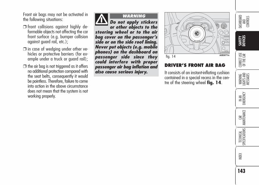
143
WARN
ING
LIGHT
S AN
D ME
SSAG
ES
IN AN
EM
ERGE
NCY
CAR
MAIN
TENA
NCE
TECH
NICA
LSP
ECIFI
CATIO
NSIN
DEX
CORR
ECT U
SE
OF TH
E CAR
DASH
BOAR
DAN
DCO
NTRO
LS
SAFE
TYDE
VICE
S
DRIVER’S FRONT AIR BAG
It consists of an instant-inflating cushioncontained in a special recess in the cen-tre of the steering wheel fig. 14.
Front air bags may not be activated inthe following situations:
❒ front collisions against highly de-formable objects not affecting the carfront surface (e.g. bumper collisionagainst guard rail, etc.);
❒ in case of wedging under other ve-hicles or protective barriers (for ex-ample under a truck or guard rail);
❒ the air bag is not triggered as it offersno additional protection compared withthe seat belts, consequently it wouldbe pointless. Therefore, failure to comeinto action in the above circumstancedoes not mean that the system is notworking properly.
Do not apply stickersor other objects to the
steering wheel or to the airbag cover on the passenger’sside or on the side roof lining.Never put objects (e.g. mobilephones) on the dashboard onpassenger side since theycould interfere with properpassenger air bag inflation andalso cause serious injury.
WARNING
A0E0077mfig. 14

144
WARN
ING
LIGHT
S AN
D ME
SSAG
ESIN
AN
EMER
GENC
YCA
RMA
INTE
NANC
ETE
CHNI
CAL
SPEC
IFICA
TIONS
INDE
XCO
RREC
T USE
OF
THE C
AR
DASH
BOAR
DAN
DCO
NTRO
LSSA
FETY
DEVI
CES
On cars fitted with front passenger’s air bag deactivation(front air bag, knees air bag (where provided) and sideon seat), these air bags shall be deactivated when plac-ing the child’s seat on the front passenger’s seat. More-over, the front passenger’s seat shall be adjusted in the
most backward position to prevent any contact between thechild’s seat and the dashboard. Even if not compulsory by law,you are recommended to reactivate the air bag immediately assoon as the child transport is no longer necessary.
A0E0078mfig. 15
With passenger’s air bag active, never place child’s seatswith the cradle facing backwards since the air bag acti-
vation could cause to the child serious injuries, even mortal.
WARNING
WARNINGPASSENGER’S FRONT AIR BAG
It consists of an instant-inflating cush-ion contained into a special recess in thedashboard fig. 15, this cushion has avolume bigger than that of the driver.

145
WARN
ING
LIGHT
S AN
D ME
SSAG
ES
IN AN
EM
ERGE
NCY
CAR
MAIN
TENA
NCE
TECH
NICA
LSP
ECIFI
CATIO
NSIN
DEX
CORR
ECT U
SE
OF TH
E CAR
DASH
BOAR
DAN
DCO
NTRO
LS
SAFE
TYDE
VICE
S
MANUAL DEACTIVATION (where provided) OF PASSENGER’S FRONT AIR BAG , KNEES AIR BAG (where provided) ANDPASSENGER’S FRONT SIDE BAG
DRIVER’S ANDPASSENGER’S KNEES AIRBAG (where provided)
Knees air bag consists of an instant-in-flating cushion housed into a specialcompartment provided for the purposeunder the steering wheel for the driverfig. 16 and into the lower part of thedashboard for the passenger fig. 17,to give further protection in the event offrontal crash.
A0E0092mfig. 17A0E0079mfig. 16
Should it be absolutely necessary to car-ry a child on the front seat, the pas-senger’s front air bag, knees air bag(where provided) and the side bag canbe deactivated. Deactivation/activationshall be performed (with key removedfrom ignition device) using the keyswitch set on the right side of dashboardfig. 18. You can reach the switch on-ly if the door is opened. When the dooris open, the metal insert of the key canbe inserted and removed in both posi-tions.
IMPORTANT Operate the switch on-ly when the engine is not running andthe ignition key is removed.The key-operated switch has two posi-tions:
❒ passenger's front air bag and kneesair bag (where provided) and sidebag activated (ON position P):warning light Fon front ceiling lightpanel off; it is absolutely prohibitedto carry a child on the front seat;
A0E0062mfig. 18

146
WARN
ING
LIGHT
S AN
D ME
SSAG
ESIN
AN
EMER
GENC
YCA
RMA
INTE
NANC
ETE
CHNI
CAL
SPEC
IFICA
TIONS
INDE
XCO
RREC
T USE
OF
THE C
AR
DASH
BOAR
DAN
DCO
NTRO
LSSA
FETY
DEVI
CES
❒ passenger's front air bag and kneesair bag (where provided) and sidebag deactivated (OFF positionF):warning light Fon front ceiling lightpanel on; it is possible to carry a childprotected by special restraint systemson the front seat.
The warning light F on front ceilinglight panel stays on permanently until thepassenger’s air bags are reactivated.
Passenger's air bags deactivation willnot inhibit the operation of the head pro-tection side bag (Window Bag).
SIDE AIR BAGS(Side bag -Window bag)
The car is fitted with front side bags fordriver and passenger for protecting thechest and window bags for protecting frontand rear occupant’s head.
Side bags protect car occupants fromside crashes of medium-high severity, byplacing the cushion between the occu-pant and the internal parts of the sidestructure of the car.
Non-activation of side bags in othertypes of collisions (front collisions, rearshunts, roll-overs, etc...) is not a systemmalfunction.
In case of side crash, an electronic con-trol unit, when required triggers the in-flation of the cushion. The cushion im-mediately inflates, placing itself as a pro-tection, between the occupant’s bodyand the structure that could cause in-juries. Immediately after, the cushion de-flates.
Side air bags are not a replacement ofbut complementary to the belts, whichyou are recommended to always wear,as specified by law in Europe and mostnon-European countries.
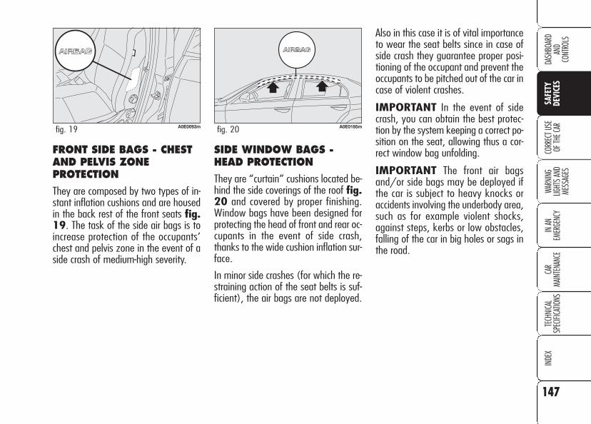
147
WARN
ING
LIGHT
S AN
D ME
SSAG
ES
IN AN
EM
ERGE
NCY
CAR
MAIN
TENA
NCE
TECH
NICA
LSP
ECIFI
CATIO
NSIN
DEX
CORR
ECT U
SE
OF TH
E CAR
DASH
BOAR
DAN
DCO
NTRO
LS
SAFE
TYDE
VICE
S
SIDE WINDOW BAGS -HEAD PROTECTION
They are “curtain” cushions located be-hind the side coverings of the roof fig.20 and covered by proper finishing.Window bags have been designed forprotecting the head of front and rear oc-cupants in the event of side crash,thanks to the wide cushion inflation sur-face.
In minor side crashes (for which the re-straining action of the seat belts is suf-ficient), the air bags are not deployed.
Also in this case it is of vital importanceto wear the seat belts since in case ofside crash they guarantee proper posi-tioning of the occupant and prevent theoccupants to be pitched out of the car incase of violent crashes.
IMPORTANT In the event of sidecrash, you can obtain the best protec-tion by the system keeping a correct po-sition on the seat, allowing thus a cor-rect window bag unfolding.
IMPORTANT The front air bagsand/or side bags may be deployed ifthe car is subject to heavy knocks oraccidents involving the underbody area,such as for example violent shocks,against steps, kerbs or low obstacles,falling of the car in big holes or sags inthe road.
FRONT SIDE BAGS - CHESTAND PELVIS ZONEPROTECTION
They are composed by two types of in-stant inflation cushions and are housedin the back rest of the front seats fig.19. The task of the side air bags is toincrease protection of the occupants’chest and pelvis zone in the event of aside crash of medium-high severity.
A0E0093mfig. 19 A0E0185mfig. 20

148
WARN
ING
LIGHT
S AN
D ME
SSAG
ESIN
AN
EMER
GENC
YCA
RMA
INTE
NANC
ETE
CHNI
CAL
SPEC
IFICA
TIONS
INDE
XCO
RREC
T USE
OF
THE C
AR
DASH
BOAR
DAN
DCO
NTRO
LSSA
FETY
DEVI
CES
IMPORTANT When the airbag in-flates it emits a small amount of dusts.These dusts are harmless and is not thebeginning of a fire; then the unfold cush-ion surface and the car interiors can becovered by a dusty remains: this dustcan irritate skin and eyes. In case of con-tact, wash yourself using neutral soapand water.
Expiration dates of pyrotechnic chargeand coil contact are indicated on the la-bel inside the glovebox. As this date ap-proaches, contact Alfa Romeo Autho-rized Services to have the device re-placed.
IMPORTANT Should an accident oc-cur in which any of the safety devices isactivated, take the car to Alfa RomeoAuthorized Services to have the devicesactivated replaced and to have the sys-tem checked.
All control, repair and replacement op-erations concerning the air bags mustonly be carried out c/o Alfa Romeo Au-thorized Services.
If you are having the car scrapped, havethe air bag system deactivated at AlfaRomeo Authorized Services first. If the carchanges ownership, the new owner mustbe informed of the method of use of airbags and the above warnings and alsobe given this “Owner’s Manual”.
IMPORTANT The triggering of pre-tensioners, front air bags and side bagsis decided in a differentiated manner ac-cording to the type of impact. The fail-ure to deploy one or more of them doesnot mean that the system is not work-ing properly.
Never rest head, armsand elbows on the
door, on the windows and inthe window bag unfoldingarea to prevent possible in-juries during the inflationphase.
WARNING
Never lean head, armsand elbows out of the
window.
WARNING

149
WARN
ING
LIGHT
S AN
D ME
SSAG
ES
IN AN
EM
ERGE
NCY
CAR
MAIN
TENA
NCE
TECH
NICA
LSP
ECIFI
CATIO
NSIN
DEX
CORR
ECT U
SE
OF TH
E CAR
DASH
BOAR
DAN
DCO
NTRO
LS
SAFE
TYDE
VICE
S
GENERAL WARNINGS
If when fitting the keyinto the ignition device,
the warning light ¬ does notturn on or if it stays on whentravelling (on certain versionstogether with the message onthe display) there could be afailure in safety systems; inthis event air bags or preten-sioners could not trigger incase of impact or, in a minornumber of cases, they couldtrigger accidentally. ContactAlfa Romeo Authorized Ser-vices immediately to have thesystem checked.
WARNINGDo not cover the back-rest of front seats with
trims or covers that are notsuitable to be used with sidebags.
WARNING
Never travel with ob-jects on your lap, in
front of your chest or with apipe, pencil, etc. between yourlips; injury may result in theevent of the air bag being trig-gered.
WARNING
Always keep yourhands on the steering
wheel rim when driving, sothat if the air bag is triggered,it can inflate without meetingany obstacles which couldcause serious harm to you. Donot drive with the body bentforwards, keep the seat backrest in the erect position andlean your back well against it.
WARNING
If the car has beenstolen or an attempt to
steal it has been made, if ithas been subjected to vandalsor floods, have the air bagsystem checked by Alfa RomeoAuthorized Services.
WARNING
Remember that withthe key fitted into the
ignition device and engine off,the air bags may be triggeredon a stationary car if it isbumped by another movingcar. Therefore, never seat chil-dren on the front seat evenwhen the car is stationary. Onthe other hand remember thatif the key is not fitted into theignition device, no safety sys-tem (air bags or pretension-ers) is triggered in the eventof an impact; in this case, fail-ure to come into action cannotbe considered as a sign thatthe system is not workingproperly.
WARNING

150
WARN
ING
LIGHT
S AN
D ME
SSAG
ESIN
AN
EMER
GENC
YCA
RMA
INTE
NANC
ETE
CHNI
CAL
SPEC
IFICA
TIONS
INDE
XCO
RREC
T USE
OF
THE C
AR
DASH
BOAR
DAN
DCO
NTRO
LSSA
FETY
DEVI
CES
The front air bag is trig-gered for shocks
greater in magnitude than thepretensioners. For impacts be-tween these two thresholds,it is therefore normal that on-ly the pretensioners are trig-gered.
WARNING
Do not hook rigid ob-jects to the coat hooks
and to the support handles.
WARNING
The air bag does notsubstitute the seat
belts, but only increases theireffectiveness. Moreover, sincethe front air bags do not comeinto operation in the event offront impact at low speed, sidecollisions, bumps from behindor overturning, in these cir-cumstances the occupantswould only be protected bythe seat belts which musttherefore always be fastened.
WARNING
Never wash seat back-rests with pressurised
water or steam (by hand or atautomatic seat washing sta-tions).
WARNING
When the key is fittedinto the ignition device,
the warning light F (with pas-senger’s front air bags deacti-vation switch at ON) turns onand flashes for few seconds toremind that passenger’s frontair bag, knees air bag and sidebag will be deployed in a crash,after which it should go off.
WARNING
151
SAFE
TYDE
VICES
WARN
ING
LIGHT
S AN
D ME
SSAG
ES
IN AN
EM
ERGE
NCY
CAR
MAIN
TENA
NCE
TECH
NICA
LSP
ECIFI
CATIO
NSIN
DEX
DASH
BOAR
DAN
DCO
NTRO
LS
CORR
ECT
USE
OF T
HE C
AR
CCOORRRREECCTT UUSSEE OOFF TTHHEE CCAARRENGINE STARTING .............................................. 152
PARKING ........................................................... 155
USING THE GEARBOX ......................................... 156
CONTAINING RUNNING COSTS ............................. 157
TOWING TRAILERS.............................................. 159
SNOW TYRES .................................................... 162
SNOW CHAINS .................................................. 163
CAR INACTIVITY ................................................ 164
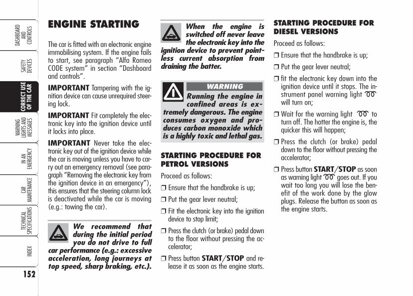
152
SAFE
TYDE
VICES
WARN
ING
LIGHT
S AN
D ME
SSAG
ESIN
AN
EMER
GENC
YCA
RMA
INTE
NANC
ETE
CHNI
CAL
SPEC
IFICA
TIONS
INDE
X
DASH
BOAR
DAN
DCO
NTRO
LSCO
RREC
T US
E OF
THE
CAR
STARTING PROCEDURE FORPETROL VERSIONS
Proceed as follows:
❒ Ensure that the handbrake is up;
❒ Put the gear lever neutral;
❒ Fit the electronic key into the ignitiondevice to stop limit;
❒ Press the clutch (or brake) pedal downto the floor without pressing the ac-celerator;
❒ Press button START/STOP and re-lease it as soon as the engine starts.
We recommend thatduring the initial periodyou do not drive to full
car performance (e.g.: excessiveacceleration, long journeys attop speed, sharp braking, etc.).
Running the engine inconfined areas is ex-
tremely dangerous. The engineconsumes oxygen and pro-duces carbon monoxide whichis a highly toxic and lethal gas.
WARNING
When the engine isswitched off never leavethe electronic key into the
ignition device to prevent point-less current absorption fromdraining the batter.
STARTING PROCEDURE FOR DIESEL VERSIONS
Proceed as follows:
❒ Ensure that the handbrake is up;
❒ Put the gear lever neutral;
❒ fit the electronic key down into theignition device until it stops. The in-strument panel warning light mwill turn on;
❒ Wait for the warning light m toturn off. The hotter the engine is, thequicker this will happen;
❒ Press the clutch (or brake) pedaldown to the floor without pressing theaccelerator;
❒ Press button START/STOP as soonas warning light m goes out. If youwait too long you will lose the ben-efit of the work done by the glowplugs. Release the button as soon asthe engine starts.
ENGINE STARTING
The car is fitted with an electronic engineimmobilising system. If the engine failsto start, see paragraph “Alfa RomeoCODE system” in section “Dashboardand controls”.
IMPORTANT Tampering with the ig-nition device can cause unrequired steer-ing lock.
IMPORTANT Fit completely the elec-tronic key into the ignition device untilit locks into place.
IMPORTANT Never take the elec-tronic key out of the ignition device whilethe car is moving unless you have to car-ry out an emergency removal (see para-graph “Removing the electronic key fromthe ignition device in an emergency”),this ensures that the steering column lockis deactivated while the car is moving(e.g.: towing the car).

153
SAFE
TYDE
VICES
WARN
ING
LIGHT
S AN
D ME
SSAG
ES
IN AN
EM
ERGE
NCY
CAR
MAIN
TENA
NCE
TECH
NICA
LSP
ECIFI
CATIO
NSIN
DEX
DASH
BOAR
DAN
DCO
NTRO
LS
CORR
ECT
USE
OF T
HE C
AR
IMPORTANT
If at start-up the engine turns off, restartit by pressing the clutch or brake pedaland then press button START/STOP.
If after a few attempts the engine doesnot start, do not insist but contact AlfaRomeo Authorized Services.
With car started the electronic key islocked into the ignition device and it canbe removed only after switching the en-gine off. With car running and keylocked into the ignition device, forcedkey removal could damage the ignitiondevice.
Start-up failures, if any, are indicated bythe turning on of the warning light Yon the instrument panel (on certain ver-sions a dedicated message is displayed).In this case contact Alfa Romeo Autho-rized Services.
If the engine will not start after pressingbutton START/STOP, repeat thestart-up procedure by pressing the oth-er pedal (clutch or brake).
Start-up failures
The system can recognise start-up fail-ures.
In the event of failure, the electronic keycan be removed from the ignition device toenable the driver to carry out the follow-ing operations:
❒ turn the instrument panel off bypressing button START/STOP orremoving the electronic key from theignition device;
❒ start the engine again by pressing theclutch/brake pedal and buttonSTART/STOP.
IMPORTANT In the event of enginelocking while the car is running, due tosafety reasons it will not be possible totake the electronic key out of the igni-tion device. To remove it, press buttonSTART/STOP with brake pedal (orclutch pedal) released and car stopped.
HOW TO WARM UP THEENGINE AFTER IT HAS JUST STARTED(petrol and diesel engines)
Proceed as follows:
❒ Drive off slowly, letting the engineturn at medium revs. Do not acceler-ate abruptly;
❒ Do not drive at full performance forthe initial kilometres. Wait until thecoolant temperature gauge startsmoving.
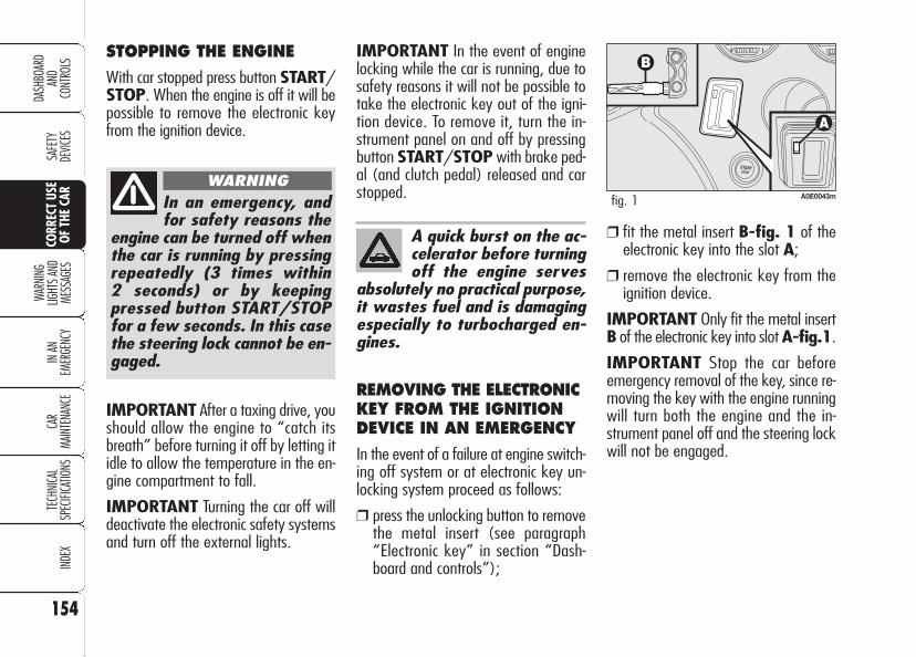
154
SAFE
TYDE
VICES
WARN
ING
LIGHT
S AN
D ME
SSAG
ESIN
AN
EMER
GENC
YCA
RMA
INTE
NANC
ETE
CHNI
CAL
SPEC
IFICA
TIONS
INDE
X
DASH
BOAR
DAN
DCO
NTRO
LSCO
RREC
T US
E OF
THE
CAR
IMPORTANT After a taxing drive, youshould allow the engine to “catch itsbreath” before turning it off by letting itidle to allow the temperature in the en-gine compartment to fall.
IMPORTANT Turning the car off willdeactivate the electronic safety systemsand turn off the external lights.
IMPORTANT In the event of enginelocking while the car is running, due tosafety reasons it will not be possible totake the electronic key out of the igni-tion device. To remove it, turn the in-strument panel on and off by pressingbutton START/STOP with brake ped-al (and clutch pedal) released and carstopped.
REMOVING THE ELECTRONICKEY FROM THE IGNITIONDEVICE IN AN EMERGENCY
In the event of a failure at engine switch-ing off system or at electronic key un-locking system proceed as follows:
❒ press the unlocking button to removethe metal insert (see paragraph“Electronic key” in section “Dash-board and controls”);
STOPPING THE ENGINE
With car stopped press button START/STOP. When the engine is off it will bepossible to remove the electronic keyfrom the ignition device.
A quick burst on the ac-celerator before turningoff the engine serves
absolutely no practical purpose,it wastes fuel and is damagingespecially to turbocharged en-gines.
❒ fit the metal insert B-fig. 1 of theelectronic key into the slot A;
❒ remove the electronic key from theignition device.
IMPORTANT Only fit the metal insertB of the electronic key into slot A-fig.1.
IMPORTANT Stop the car beforeemergency removal of the key, since re-moving the key with the engine runningwill turn both the engine and the in-strument panel off and the steering lockwill not be engaged.
A0E0043mfig. 1In an emergency, andfor safety reasons the
engine can be turned off whenthe car is running by pressingrepeatedly (3 times within 2 seconds) or by keepingpressed button START/STOPfor a few seconds. In this casethe steering lock cannot be en-gaged.
WARNING

155
SAFE
TYDE
VICES
WARN
ING
LIGHT
S AN
D ME
SSAG
ES
IN AN
EM
ERGE
NCY
CAR
MAIN
TENA
NCE
TECH
NICA
LSP
ECIFI
CATIO
NSIN
DEX
DASH
BOAR
DAN
DCO
NTRO
LS
CORR
ECT
USE
OF T
HE C
AR
To release the handbrake proceed as fol-lows:
❒ Slightly lift the handbrake A andpress release button B;
❒ Keep button B pressed and lower thelever. Warning light x on the in-strument panel will turn off.
Press the brake pedal when carrying outthis operation to prevent the car frommoving accidentally.HANDBRAKE
The handbrake lever A-fig. 2 is locat-ed between the two front seats. Pull thehandbrake lever A upwards, until thecar cannot be moved.
With electronic key fitted into the igni-tion device, the instrument panel warn-ing light x will come on.
IMPORTANT The car shall stop aftera few clicks of the handbrake lever. Ifthis is not the case, contact Alfa RomeoAuthorized Services to have the hand-brake adjusted.
A0E0030mfig. 2
PARKING THE CAR
Proceed as follows:
❒ Stop the engine and engage thehandbrake;
❒ Engage a gear (on a slope, engagefirst gear if the car is faced uphill orreverse if it is faced downhill) andleave the wheels steered.
Block the wheels with a wedge or a stoneif the car is parked on a steep slope. Donot leave the electronic key in the igni-tion switch to prevent draining the bat-tery.
Never leave children un-attended in the car. Al-
ways remove the electronic keyfrom the ignition device whenleaving the car and take it outwith you.
WARNING

156
SAFE
TYDE
VICES
WARN
ING
LIGHT
S AN
D ME
SSAG
ESIN
AN
EMER
GENC
YCA
RMA
INTE
NANC
ETE
CHNI
CAL
SPEC
IFICA
TIONS
INDE
X
DASH
BOAR
DAN
DCO
NTRO
LSCO
RREC
T US
E OF
THE
CAR
IMPORTANT The car can only be putinto reverse gear when it has stoppedmoving completely. With the engine run-ning, before engaging the reverse, waitat least 3 seconds with the clutch ped-al fully down to prevent damage andgrating of the gears.
A0E0151mfig. 4
To change gears prop-erly you must push the
clutch pedal fully down. It istherefore essential that thereis nothing under the pedals:make sure mats are lying flatand do not get in the way ofthe pedals.
WARNING
Do not drive with yourhand resting on the gearlever as the force ex-
erted, even if slight, could leadover time to premature wear onthe gearbox internal compo-nents.
USING THEGEARBOX
The car can be fitted with 6-gear or 5-gear manual gearbox (1.8 version).Gear positions are shown on thegearshift lever knob.
Always press down the clutch pedalwhen shifting gears. To engage the 6th
gear, move the gearshift lever pressingslightly rightwards to prevent engagingthe 4th gear accidentally.
To engage reverse R from neutral, raisering A-fig. 3 or A-fig. 4 under theknob and at the same time move thegearshift lever leftwards and then for-ward. After engaging reverse release thering. To shift from reverse to anothergear it is not necessary to raise the ring.
A0E0397mfig. 3

157
SAFE
TYDE
VICES
WARN
ING
LIGHT
S AN
D ME
SSAG
ES
IN AN
EM
ERGE
NCY
CAR
MAIN
TENA
NCE
TECH
NICA
LSP
ECIFI
CATIO
NSIN
DEX
DASH
BOAR
DAN
DCO
NTRO
LS
CORR
ECT
USE
OF T
HE C
AR
Climate control
The air conditioner is an additional loadwhich greatly affects the engine leadingto higher consumption. When the tem-perature outside the car permits it, usethe air vents where possible.
Spoilers
The use of aerodynamic optional extraswhich are not certified for the specificuse on the vehicle, may reduce the aero-dynamic penetration of the vehicle andincrease consumption.
Unnecessary loads
Do not travel with too much luggagestowed in the boot. The weight of thecar (especially when driving in town)and its trim greatly affects consumptionand stability.
Roof rack/ski rack
Remove the roof rack or the ski rackfrom the roof as soon as they are nolonger used. These accessories lower airpenetration and adversely affect con-sumption levels. When needing to car-ry particularly voluminous objects, prefer-ably use a trailer.
Electric devices
Use electric devices only for the amountof time needed. Rear heated window,additional headlights, windscreen wipersand heater fan need a considerableamount of energy, therefore increasingthe requirement of current increases fu-el consumption (up to +25% in the ur-ban cycle).
CONTAININGRUNNING COSTSHere are some suggestions which mayhelp you to keep the running costs ofyour car down and lower the amount oftoxic emissions released into the at-mosphere.
GENERAL CONSIDERATIONS
Car maintenance
Have checks and adjustments carried outin accordance with the “Service sched-ule”.
Tyres
Check the pressure of the tyres routine-ly at an interval of no more than 4weeks: if the pressure is too low, con-sumption levels increase as resistanceto rolling is higher.
158
SAFE
TYDE
VICES
WARN
ING
LIGHT
S AN
D ME
SSAG
ESIN
AN
EMER
GENC
YCA
RMA
INTE
NANC
ETE
CHNI
CAL
SPEC
IFICA
TIONS
INDE
X
DASH
BOAR
DAN
DCO
NTRO
LSCO
RREC
T US
E OF
THE
CAR
Gear selection
As soon as the conditions of the trafficand road allow, use a higher gear. Us-ing a low gear to obtain brilliant perfor-mance increases consumption. In thesame way improper use of a high gearincreases consumption, emissions an en-gine wear.
Top speed
Fuel consumption considerably increas-es with speed. Avoid superfluous brak-ing and accelerating, which cost in termsof both fuel and emissions.
Acceleration
Accelerating violently increasing the revswill greatly affect consumption and emis-sions: acceleration should be gradual andshould not exceed the maximum torque.
CONDITIONS OF USE
Cold starting
Short journeys and frequent cold startsdo not allow the engine to reach opti-mum operating temperature. This resultsin a significant increase in consumptionlevels (from +15 to +30% on the urbancycle) and emission of harmful sub-stances.
Traffic and road conditions
Rather high consumption levels are tiedto situations with heavy traffic, for ex-ample in queues with frequent use ofthe lower gears or in cities with manytraffic lights. Also winding mountainroads and rough road surfaces adverse-ly affect consumption.
Traffic hold-ups
During prolonged hold-ups (e.g.: levelcrossings) the engine should beswitched off.
DRIVING STYLE
Starting
Do not warm the engine with the carat a standstill or at idle or high speed:under these conditions the enginewarms up much more slowly, increasingelectrical consumption and emissions. Itis therefore advisable to move off im-mediately, slowly, avoiding high speeds.This way the engine will warm faster.
Unnecessary actions
Avoid accelerating when waiting at traf-fic lights or before switching off the en-gine. This and also double declutchingis absolutely pointless on modern carsand also increase consumption and pol-lution.

159
SAFE
TYDE
VICES
WARN
ING
LIGHT
S AN
D ME
SSAG
ES
IN AN
EM
ERGE
NCY
CAR
MAIN
TENA
NCE
TECH
NICA
LSP
ECIFI
CATIO
NSIN
DEX
DASH
BOAR
DAN
DCO
NTRO
LS
CORR
ECT
USE
OF T
HE C
AR
Engage a low gear when driving down-hill, rather than constantly using thebrake.
The weight the trailer exerts on the cartow hook reduces by the same amountthe actual car loading capacity. To makesure the maximum towable weight isnot exceeded (given in the log book)account should be taken of the fullyladen trailer, including accessories andpersonal belongings.
Do not exceed the speed limits of thecountry you are driving in. In any casedo not exceed 100 km/h.
TOWING TRAILERS
IMPORTANT NOTES
For towing caravans or trailers the carmust be fitted with a certified tow hookand an adequate electric system. In-stallation should be carried out by spe-cialised personnel who release a specialdocument for circulation on the road.
Install any specific and/or additionalrear-view mirrors as specified by law.
Remember that when towing a trailer,steep hills are harder to climb, the brak-ing spaces increase and overtaking takeslonger depending on the overall weight.
The ABS system withwhich the car may be
fitted does not control thetrailer braking system. Drivewith extreme care on slipperyroadbeds.
WARNING
Under no circumstancesshould the car brake
system be altered to controlthe trailer brake. The trailerbraking system must be fullyindependent of the car hy-draulic system.
WARNING

160
SAFE
TYDE
VICES
WARN
ING
LIGHT
S AN
D ME
SSAG
ESIN
AN
EMER
GENC
YCA
RMA
INTE
NANC
ETE
CHNI
CAL
SPEC
IFICA
TIONS
INDE
X
DASH
BOAR
DAN
DCO
NTRO
LSCO
RREC
T US
E OF
THE
CAR
For the electric connection a unified con-nector should be used which is gener-ally placed on a special bracket normallyfastened to the towing device.
For the electrical connection, 7 pin12VDC connection is to be used (CU-NA/UNI and ISO/DIN Standards). Fol-low the instructions provided by the carmanufacturer and/or the tow hitch man-ufacturer.
An electric brake or other device (elec-tric winch, etc.), if required, should besupplied directly by the battery througha cable with a cross section of no lessthan 2.5 mm2. In addition to the elec-trical branches, the car’s electric systemcan only be connected to the supply ca-ble for an electric brake and to the ca-ble for an internal light, though notabove 15W.
Assembly diagram fig. 4
The tow hook structure must be fas-tened in the points shown by the sym-bol Ø using a total of 8 M10 screws.
Fastening points (1) shall be fitted withspacers with 20x4 mm diameter.
Counterplate (2) shall have 5 mm min-imum thickness.
The counter-plates (3) shall have min.thickness of 6 mm.
IMPORTANT It is compulsory to fas-ten a label (plainly visible) of suitablesize and material with the followingwording:
MAX LOAD ON BALL 75 kg
After fitting, screw holes shall be sealedto prevent exhaust gas inlet.
IMPORTANT The hook should be fas-tened to the body avoiding any type ofdrilling and trimming of the bumper.
INSTALLING THE TOW HOOK
The towing device should be fastenedto the body by specialised personnel ac-cording to any additional and/or inte-grative information supplied by the Man-ufacturer of the device.
The towing device must meet currentregulations with reference to 94/20/ECDirective and subsequent amendments.
For any version the towing device usedmust match the towable weight of thecar on which it is to be installed.

161
SAFE
TYDE
VICES
WARN
ING
LIGHT
S AN
D ME
SSAG
ES
IN AN
EM
ERGE
NCY
CAR
MAIN
TENA
NCE
TECH
NICA
LSP
ECIFI
CATIO
NSIN
DEX
DASH
BOAR
DAN
DCO
NTRO
LS
CORR
ECT
USE
OF T
HE C
AR
fig. 4 A0E0398m
REAR
AXL
E
Stan
dard
tow
bal
l
full
load

162
SAFE
TYDE
VICES
WARN
ING
LIGHT
S AN
D ME
SSAG
ESIN
AN
EMER
GENC
YCA
RMA
INTE
NANC
ETE
CHNI
CAL
SPEC
IFICA
TIONS
INDE
X
DASH
BOAR
DAN
DCO
NTRO
LSCO
RREC
T US
E OF
THE
CAR
Due to the snow tyre features, undernormal conditions of use or on long mo-torway journeys, the performance ofthese tyres is lower than that of normaltyres. It is therefore necessary to limittheir use to the purposes for which theyare certified.
IMPORTANT When snow tyres areused with a max speed index below theone that can be reached by the car (in-creased by 5%), place a notice in thepassenger compartment, plainly in thedriver’s view which states the max per-missible speed of the snow tyres (as perEC Directive).
All four tyres should be the same (brandand track) to ensure greater safetywhen driving and braking and better dri-veability.
Remember that it is inappropriate tochange the direction of rotation of tyres.
SNOW TYRES
Use snow tyres of the same size as thenormal tyres provided with the car.
Alfa Romeo Authorized Services will beglad to provide advice concerning themost suitable type of tyre for the cus-tomer’s requirements.
For the type of tyre to be used, inflationpressures and the specifications of snowtyres, follow the instructions given in para-graph “Wheels” in section “Technicalspecifications”.
The winter features of these tyres are re-duced considerably when the treaddepth is below 4 mm. In this case, theyshould be replaced.
The max speed forsnow tyres with “Q”
marking is 160 km/h; 190km/h for tyres with “T”marking and 210 km/h fortyres with H marking. TheRoad Traffic Code speed lim-its must however be alwaysstrictly observed.
WARNING

163
SAFE
TYDE
VICES
WARN
ING
LIGHT
S AN
D ME
SSAG
ES
IN AN
EM
ERGE
NCY
CAR
MAIN
TENA
NCE
TECH
NICA
LSP
ECIFI
CATIO
NSIN
DEX
DASH
BOAR
DAN
DCO
NTRO
LS
CORR
ECT
USE
OF T
HE C
AR
IMPORTANT Snow chains cannot befitted to the space-saver spare wheel.So, if a front (drive) wheel is puncturedand chains are needed, a rear wheelshould be fitted to the front of the carand the spare wheel should be fitted tothe rear (adjust tyre pressure to the spec-ified value as soon as possible). Thisway with two normal drive wheels,snow chains can be fitted to them tosolve an emergency.
Tyres 235/45 R18” can-not be fitted with snowchains due to interference
with the fender.
Also for 3.2 JTS version,snow chains shall be fit-ted on the FRONT axle of
the car.
SNOW CHAINS
Use of snow chains should be in compli-ance with local regulations.
Snow chains should only be applied tothe driving wheels (front wheels).
Check the tension of the chains after thefirst few metres have been driven.
Use snow chains with reduced size: fortyres 205/55 R16” and 215/55R16” use snow chains with reduced sizewith max protrusion beyond the tyre pro-file of 9 mm.
Use of snow chains may be compulso-ry also for cars with four-wheel drive.
Traditional snow chainsmay not be used on tyrestype 225/50 R17” on-
ly spider type chains can be used.
Keep your speed downwhen snow chains arefitted. Do not exceed40 km/h. Avoid pot-holes, steps and pave-
ments and avoid also to drivefor long distances on roads notcovered with snow to preventdamaging the car and theroadbed.
WARNING
When snow chains arefitted, switch the ASRsystem off. Press the
ASR/VDC button (see para-graph “ASR system” in section“Dashboard and controls”).

164
SAFE
TYDE
VICES
WARN
ING
LIGHT
S AN
D ME
SSAG
ESIN
AN
EMER
GENC
YCA
RMA
INTE
NANC
ETE
CHNI
CAL
SPEC
IFICA
TIONS
INDE
X
DASH
BOAR
DAN
DCO
NTRO
LSCO
RREC
T US
E OF
THE
CAR
CAR INACTIVITY
If the car is to be left inactive for longerthan a month, the following precautionsshould be noted:
❒ park the car in covered, dry and ifpossible well-ventilated premises;
❒ engage a gear;
❒ check that the handbrake is not en-gaged;
❒ disconnect battery negative terminaland check the battery charge. Thischeck is to be repeated every threemonths when the car is left inactive.Recharge if the optical(where pro-vided) indicator shows a dark colourwithout the central green area (seeparagraph “Battery” in “Car main-tenance” section);
❒ clean and protect the painted partsusing protective wax;
❒ clean and protect the shiny metalparts using special compounds read-ily available;
❒ sprinkle talcum powder on the rubberwindscreen and rear window wiperblades and lift them off the glass;
❒ slightly open the windows;
❒ cover the car with a cloth or perfo-rated plastic sheet. Do not use sheetsof non-perforated plastic as they donot allow moisture on the car bodyto evaporate;
❒ inflate tyres to +0.5 bar above thenormal specified pressure and checkit at intervals;
❒ if you don’t disconnect the batteryfrom the electric system, check itscharge every month and recharge itif the optical indicator shows a darkcolour without the central green area;
❒ do not drain the engine cooling sys-tem.
IMPORTANT If the car is fitted withalarm system, switch off the alarm withthe remote control.

165
SAFE
TYDE
VICES
IN AN
EM
ERGE
NCY
CAR
MAIN
TENA
NCE
TECH
NICA
LSP
ECIFI
CATIO
NSIN
DEX
CORR
ECT U
SE
OF TH
E CAR
DASH
BOAR
DAN
DCO
NTRO
LS
WAR
NING
LIG
HTS
AND
MES
SAGE
S
WWAARRNNIINNGG LLIIGGHHTTSS AANNDD MMEESSSSAAGGEESSLOW BRAKE FLUID/HANDBRAKE ON..................... 167BRAKE PAD WEAR ............................................. 167SEAT BELTS NOT FASTENED ................................. 167AIR BAG FAILURE................................................ 168PASSANGER’S FRONT AIR BAGS DEACTIVATED ........ 169ENGINE COOLANT HIGH TEMPERATURE.................. 169ENGINE OIL HIGH TEMPERATURE .......................... 170LOW ENGINE OIL PRESSURE/ EXHAUST OIL..................................................... 170LOW BATTERY CHARGE ....................................... 170INCOMPLETE DOOR LOCKING ............................... 171BONNET OPEN................................................... 171BOOT OPEN....................................................... 171INJECTION SYSTEM FAILURE/EOBD SYSTEM FAILURE....................................... 171CAR PROTECTION SYSTEM FAILURE/STEERING LOCK INHIBITION................................. 172ALARM FAILURE/BREAK-IN ATTEMPTELECTRONIC KEY NOT RECOGNIZED ...................... 172POSSIBLE PRESENCE OF ICE ON THE ROAD............ 173PRE-HEATING GLOW PLUGS/PRE-HEATING GLOW PLUG FAILURE ....................... 173WATER IN DIESEL FUEL FILTER ............................. 174INERTIAL FUEL CUT-OFF SWITCHED ON ................. 174ABS SYSTEM FAILURE......................................... 175EBD SYSTEM FAILURE......................................... 175
VDC SYSTEM .................................................... 175HILL HOLDER FAILURE ........................................ 176ASR SYSTEM (WHEEL ANTISKID SYSTEM)............. 176EXTERNAL LIGHTS FAILURE .................................. 176BRAKE LIGHTS FAILURE ....................................... 177REAR FOGLIGHTS ............................................... 177FRONT FOG LIGHTS ............................................ 177SIDE/TAILLIGHTS/FOLLOW ME HOME.................. 177DIPPED BEAM HEADLIGHTS.................................. 177MAIN BEAM HEADLIGHTS .................................... 177LEFT-HAND DIRECTION INDICATOR ........................ 177RIGHT-HAND DIRECTION INDICATOR ...................... 177LIGHT SENSOR FAILURE........................................ 178RAIN SENSOR FAILURE......................................... 178PARKING SENSORS FAILURE ................................ 178FUEL RESERVE – LIMITED CRUISING RANGE .......... 178CRUISE CONTROL .............................................. 178DIESEL PARTICULATE FILTER CLOGGED .................. 178ANTIPINCH SYSTEM FAILURE ............................... 179WINDSCREEN WASHER FLUID LOW LEVEL ............. 179SPEED LIMIT EXCEEDED ..................................... 179T.P.M.S. SYSTEM FAILURE ................................... 179CHECK TYRE PRESSURE ...................................... 179LOW INFLATION PRESSURE ................................. 180TYRE PRESSURE UNSUITABLE FOR SPEED ............. 180

166
SAFE
TYDE
VICES
IN AN
EM
ERGE
NCY
CAR
MAIN
TENA
NCE
TECH
NICA
LSP
ECIFI
CATIO
NSIN
DEX
CORR
ECT U
SE
OF TH
E CAR
DASH
BOAR
DAN
DCO
NTRO
LS
WAR
NING
LIG
HTS
AND
MES
SAGE
SVery serious failures
These failures are repeated on the displayindefinitely and stop any previous indi-cation on the display. These failures arerepeated each time the key is fitted intothe ignition device until the cause of mal-functioning is removed. To stop this “cy-cle” press button MENU: in this casethe failure symbol stays on the display atthe bottom of the screen until the causeof malfunctioning is removed.
WARNING LIGHTSAND MESSAGES
GENERAL WARNINGS
Failure indications shown on the displayare divided into two categories: very se-rious and less serious failures.
Every failure indication is accompaniedby the turning on of the relevant warn-ing light (where provided) and by ded-icated warning messages, if any.
In certain cases, failure indications canbe accompanied by the sound of abuzzer (adjustable).
These indications are concise and cau-tionary and are aimed to suggest theprompt action the driver must adoptwhen a car malfunctioning appears.These indications, however, shall not beconsidered as exhaustive and/or as analternative to the specifications con-tained in this “Owner’s Manual”, whichshall always be read through carefullyand thoroughly.
In case of failure indication always referto the specifications contained in thissection.
Serious failures
These failures are repeated on the displayfor about 20 seconds and then they gooff. These failures are repeated each timethe key is fitted into the ignition device.At the end of the displaying cycle (ap-prox. 20 seconds), or when pressing but-ton MENU, the failure symbol will stayon the display at the bottom of the screenuntil the cause of malfunctioning is re-moved.

167
SAFE
TYDE
VICES
IN AN
EM
ERGE
NCY
CAR
MAIN
TENA
NCE
TECH
NICA
LSP
ECIFI
CATIO
NSIN
DEX
CORR
ECT U
SE
OF TH
E CAR
DASH
BOAR
DAN
DCO
NTRO
LS
WAR
NING
LIG
HTS
AND
MES
SAGE
S
SEAT BELTS NOT FASTENED (red)
The warning light turns onglowing steadily when:
❒ the driver's seat belt is not fastenedcorrectly;
❒ the passenger's seat belt is not fas-tened correctly, heavy objects areplaced on the passenger's seat;
❒ unfastening the driver's or the pas-senger's seat belt.
With car moving the warning light willturn on flashing together with the buzzerfor a short time.
The warning light will then stay on glow-ing steadily.
BRAKE PAD WEAR (amber)
The warning light (where pro-vided) turn on (on certain versions to-gether with the message on the display)if the front brake pads are worn; in thiscase have them changed as soon as pos-sible.
IMPORTANT Since the car is fittedwith wear sensors for the front brakepads, when changing them, check alsothe rear brake pads.
d
<If the warning lightturns on when travel-
ling, check that the handbrakeis not engaged. If the warninglight stays on with handbrakedisengaged, stop the car im-mediately and contact AlfaRomeo Authorized Services.
WARNINGLOW BRAKEFLUID(red)
HANDBRAKE ON(red)
Fitting the key into the ignition devicethe warning light turns on, but it shouldgo off after few seconds.
Low brake fluid levelThe warning light turns on (on certainversions a dedicated message is dis-played) when the level of the brake flu-id in the reservoir falls below the mini-mum level, due to possible leak in thecircuit.
Handbrake onThe warning light turns on when thehandbrake is on.
x

168
SAFE
TYDE
VICES
IN AN
EM
ERGE
NCY
CAR
MAIN
TENA
NCE
TECH
NICA
LSP
ECIFI
CATIO
NSIN
DEX
CORR
ECT U
SE
OF TH
E CAR
DASH
BOAR
DAN
DCO
NTRO
LS
WAR
NING
LIG
HTS
AND
MES
SAGE
SAIR BAG FAILURE(red)
Fitting the key into the ignitiondevice the warning light turns on, butit should go off after few seconds.
The warning light stays on glowingsteadily (on certain versions togetherwith the message on the display) to in-dicate a failure in the air bag system.
¬
If the ¬ warning lightdoes not turn on when
fitting the key into the ignitiondevice, or if stays on whentravelling (on certain versionstogether with the message onthe display), this could indicatea failure in safety retaining sys-tem; under this condition airbags or pretensioners could nottrigger in the event of collisionor, in a restricted number ofcases, they could trigger acci-dentally. Before restarting con-tact Alfa Romeo AuthorizedServices.
WARNING
The buzzer can be muted temporarily bythe following procedure:
❒ fasten the front seat belts;
❒ fit the electronic key into the ignition de-vice;
❒ wait for over 20 seconds but less than1 minute and then unfasten one of thefront seat belts.
This procedure will stand valid till next en-gine switching off.
For permanent deactivation, contact AlfaRomeo Authorized Services. The S.B.R.system can only be reset through the set-up menu (see paragraph “Reconfigurablemultifunction display“ in section “Dash-board and controls”).
Failure of the ¬ warn-ing light is indicated by
the flashing for more than thenormal 4 seconds of the pas-senger's front air bag deacti-vated warning light F. In ad-dition, the air bag system willdeactivate automatically thepassenger's front air bag (frontand side where provided). Inthis event warning light ¬could not indicate failure insafety systems. Before restart-ing contact Alfa Romeo Autho-rized Services immediately tohave the system checked.
WARNING
169
SAFE
TYDE
VICES
IN AN
EM
ERGE
NCY
CAR
MAIN
TENA
NCE
TECH
NICA
LSP
ECIFI
CATIO
NSIN
DEX
CORR
ECT U
SE
OF TH
E CAR
DASH
BOAR
DAN
DCO
NTRO
LS
WAR
NING
LIG
HTS
AND
MES
SAGE
S
PASSENGER’SFRONT AIR BAGSDEACTIVATED (amber)
The warning light (set on the front ceil-ing light panel) turns on when passen-ger’s front air bags, passenger’s kneesair bag (where provided) and passen-ger’s front side bag are deactivatedthrough the relevant key switch (for ver-sions/markets where applicable).
With passenger's air bags active, whenfitting the electronic key into the ignitiondevice the warning light will turn on forabout 4 seconds, will flash for the next4 seconds and then it will turn off.
F– Car heavy duty(e.g.: towing trail-er uphill or fully laden car): decreasespeed, if the warning light stays on, stopthe car. Wait for 2 or 3 minutes leavingthe engine on and slightly accelerated tofurther activate the circulation of thecoolant fluid, then switch the engine off.
IMPORTANT Under severe use of thecar, keep the engine on and slightly ac-celerated for few minutes before switch-ing it off.
Warning light Ffailureis indicated by warning
light¬. In addition, the air bagsystem will deactivate auto-matically the passenger's frontair bag (front and side). Beforerestarting contact Alfa RomeoAuthorized Services immedi-ately to have the systemchecked.
WARNING
ENGINE COOLANT HIGH TEMPERATURE (red)
Fitting the key into the ignition device,the warning light (set on engine coolantgauge) turns on but it shall go off aftera few seconds.
The warning light turns on (on certainversions a dedicated message is dis-played) to indicate engine overheating.
If the warning light comes on, proceedas follows:
– Normal driving conditions: stopthe car, switch off the engine and checkwhether the water level in the reservoiris not below the MIN marl. Otherwisewait for few seconds to allow enginecooling, then open slowly and carefullythe cap, top up coolant and checkwhether its level is falling between MINand MAX marks in the reservoir. Checkvisually any leak. If when restarting thewarning light comes on again, contactAlfa Romeo Authorized Services.
u
With engine hot, do notremove the cap: risk of
burnt.
WARNING

170
SAFE
TYDE
VICES
IN AN
EM
ERGE
NCY
CAR
MAIN
TENA
NCE
TECH
NICA
LSP
ECIFI
CATIO
NSIN
DEX
CORR
ECT U
SE
OF TH
E CAR
DASH
BOAR
DAN
DCO
NTRO
LS
WAR
NING
LIG
HTS
AND
MES
SAGE
SENGINE OIL HIGH TEMPERATURE
Fitting the key into the ignitiondevice, the warning light (set on engineoil temperature gauge) turns on but itshould go off after a few seconds. Warn-ing light turning on when travelling (oncertain versions together with the mes-sage on the display) indicates that en-gine oil is too hot; switch the engine offand contact Alfa Romeo Authorized Ser-vices.
If warning light `starts flashing whentravelling contact Alfa
Romeo Authorized Services.
LOW ENGINE OIL PRESSURE
EXHAUST OIL (diesel versions)
Low engine oil pressure
On certain versions, fitting the key intothe ignition device, the warning lightturns on but it should go off as soon asthe engine has started.
After the first indication, at each enginestarting the warning light v will goon flashing for about 1 minute and thenevery 2 hours until oil is changed.
LOW BATTERYCHARGE (red)
The warning light (where pro-vided) turns on, but it should go off assoon as the engine has started (with theengine running at idle speed a brief de-lay in going out is allowed).
If the warning light (or as an alternative,on certain versions, a symbol and a mes-sage are displayed) stays on glowingsteadily or flashing contact immediate-ly Alfa Romeo Authorized Services.
w
` v
If the warning light(or as an alternative,
on certain versions, a symboland a message are displayed)comes on when travelling,stop immediately and contactAlfa Romeo Authorized Ser-vices.
WARNING
If warning light vstarts flashing, contactAlfa Romeo Authorized
Services as soon as possible tohave the engine oil changed andthe instrument panel (or symbolv on the display) switchedoff.
Exhaust oil (diesel versions)
The warning light (where provided) withturn on flashing (on certain versions amessage is displayed) when the systemdetects that the engine oil is exhaust.

171
SAFE
TYDE
VICES
IN AN
EM
ERGE
NCY
CAR
MAIN
TENA
NCE
TECH
NICA
LSP
ECIFI
CATIO
NSIN
DEX
CORR
ECT U
SE
OF TH
E CAR
DASH
BOAR
DAN
DCO
NTRO
LS
WAR
NING
LIG
HTS
AND
MES
SAGE
S
BOOT OPEN
On certain versions messageand symbol R (red) are
displayed to indicate that boot isopen.
BONNET OPEN (where provided)
On certain versions messageand symbol S (red) are displayed toindicate that bonnet is open.
INJECTION SYSTEM FAILURE (dieselversions - amber) EOBD SYSTEM FAILURE (petrol versions - amber)(optional forversions/marketswhere applicable)
Injection system failure
Fitting the key into the ignition devicethe warning light turns on, but it shouldgo off when the engine has started.
The warning light stays on or it turns onwhen travelling to indicate a malfunc-tion in the injection/exhaust systemwith possible lack of performance, poordriveability and high consumption.
In these conditions it is possible to con-tinue driving without however requiringheavy effort or high speed from the en-gine. In any case, contact Alfa RomeoAuthorized Services as soon as possible.
EOBD system failure(optional for versions/markets where applicable)
Under normal conditions, fitting the elec-tronic key into the ignition device, thewarning light turns on, but it should gooff when the engine has started. This in-dicates proper operation of the warn-ing light.
If the warning light stays on or turns onwhen travelling:
– glowing steadily (on certain ver-sions together with the message on thedisplay): means a fault in the sup-ply/ignition system which could causehigh emissions at the exhaust, possiblelack of performance, poor handling andhigh consumption levels. In these con-ditions it is possible to continue drivingwithout however requiring heavy effortor high speed from the engine. Pro-longed use of the car with the warninglight on may cause damages. ContactAlfa Romeo Authorized Services as soonas possible.
The warning light goes off if the faultdisappears, but it is however stored bythe system.
INCOMPLETE DOORLOCKING (red)
The warning light (where pro-vided) (or symbol on the display) turnson when one or more doors, the boot orthe bonnet (where provided) are notproperly shut.
U´
S
R
172
SAFE
TYDE
VICES
IN AN
EM
ERGE
NCY
CAR
MAIN
TENA
NCE
TECH
NICA
LSP
ECIFI
CATIO
NSIN
DEX
CORR
ECT U
SE
OF TH
E CAR
DASH
BOAR
DAN
DCO
NTRO
LS
WAR
NING
LIG
HTS
AND
MES
SAGE
SCAR PROTECTIONSYSTEM FAILURE (amber)
STEERING LOCKINHIBITION(amber)
Car protection system failure
Warning light (where provided) comingon (on certain versions a message is dis-played) indicates car protecting systemfailure: in this event contact Alfa RomeoAuthorized Services as soon as possible.
Steering lock inhibition
Warning light (where provided) turns on(on certain versions a message is dis-played) when removing the electronickey from the ignition device when thecar has turned off while travelling.
ALARM FAILURE(where provided)(amber)BREAK-IN ATTEMPT (amber)ELECTRONIC KEYNOT RECOGNIZED (amber)
Alarm failure
The turning on of the warning light (whereprovided) (on certain versions a messageis displayed) indicates that there is a fail-ure in the alarm system. Contact AlfaRomeo Authorized Services as soon aspossible.
Break-in attempt
The turning on of the warning light (whereprovided) (on certain versions a messageis displayed) indicates an attempt ofbreak-in. Contact Alfa Romeo AuthorizedServices as soon as possible.
Electronic key not recognized
The turning on of the warning light (whereprovided) (on certain versions a messageis displayed) indicates that the electronickey being used is not enabled.
– flashing: indicates the possibility ofdamage to the catalyst (see “EOBD sys-tem” in section “Dashboard and con-trols”). If the light flashes, it is neces-sary to release the accelerator pedal tolower the speed of the engine until thewarning light stops flashing; continuethe journey at moderate speed, tryingto avoid driving conditions that maycause further flashing and contact AlfaRomeo Authorized Services as soon aspossible.
If when fitting the key in-to the ignition device, thewarning light U does
not turn on or if turns on withfixed light or flashing when thecar is travelling, contact AlfaRomeo Authorized Services assoon as possible. Warning lightU operation can by checked bytraffic agents by proper equip-ment therefore, comply withlaws and regulations in force inthe country where you are dri-ving.
> Y

173
SAFE
TYDE
VICES
IN AN
EM
ERGE
NCY
CAR
MAIN
TENA
NCE
TECH
NICA
LSP
ECIFI
CATIO
NSIN
DEX
CORR
ECT U
SE
OF TH
E CAR
DASH
BOAR
DAN
DCO
NTRO
LS
WAR
NING
LIG
HTS
AND
MES
SAGE
S
This cycle is performed only once whenthe outside temperature read is lowerthan or equal to 3°C and it can be re-peated only when outside temperatureexceeds6 °C and then falls down to 3 °C or be-low.
IMPORTANT In the event of outsidetemperature sensor failure, the displaywill show dashes instead of the value.
PRE-HEATINGGLOW PLUGS(diesel versions - amber)
PRE-HEATINGGLOW PLUGSFAILURE (dieselversions - amber)
Pre-heating glow plugs
Fitting the key into the ignition devicethe warning light turns on and it will turnoff when glow plugs reach the presettemperature. Start the engine immedi-ately after warning light switching off.
IMPORTANT With mild or hot ambi-ent temperature, warning light stays onfor very short time.
m
POSSIBLE PRESENCE OF ICEON THE ROAD
When the outside temperature reachesor falls below 3°C, the display will showa warning message, symbol √, and abuzzer will sound to warn the driver ofthe possible presence of ice on the road.
On certain versions, once the abovewarning indication cycle is over or whenpressing briefly the button MENU:
– the displayed message goes off andpreviously active screen is displayedagain;
– temperature indication stops flashing;
– symbol √ stays displayed at the bot-tom right of the screen (until outsidetemperature is lower than or equal to6°C).

174
SAFE
TYDE
VICES
IN AN
EM
ERGE
NCY
CAR
MAIN
TENA
NCE
TECH
NICA
LSP
ECIFI
CATIO
NSIN
DEX
CORR
ECT U
SE
OF TH
E CAR
DASH
BOAR
DAN
DCO
NTRO
LS
WAR
NING
LIG
HTS
AND
MES
SAGE
SINERTIAL FUEL CUT-OFF SWITCHED ON
On certain versions, the inter-vention of the inertial fuel cut-off switchis indicated by a message + symbol(amber) on the display.
Pre-heating glow plugs failure
The warning light (on certain versionstogether with the message on the dis-play) will flash to indicate a failure inthe pre-heating glow plugs system. Con-tact Alfa Romeo Authorized Services assoon as possible to have the failure elim-inated.
WATER IN FUEL FILTER(diesel versions -amber)
The warning light turns on glowingsteadily when travelling (on certain ver-sions together with the message on thedisplay) to indicate that there is waterin the diesel fuel filter.
c
The presence of water inthe fuel circuit maycause serious damage to
the entire injection system andcause irregular engine opera-tion. If the warning light c onthe dial turns on (on certain ver-sions together with the mes-sage on the display) contact Al-fa Romeo Authorized Servicesas soon as possible to have thesystem relieved. If the aboveindications come on immediate-ly after refuelling, water hasprobably been poured into thetank: turn the engine off imme-diately and contact Alfa RomeoAuthorized Services.
If, after a crash, yousmell fuel or see leaks
from the fuel system, do notreset the switch to avoid firerisk.
WARNING
s

175
SAFE
TYDE
VICES
IN AN
EM
ERGE
NCY
CAR
MAIN
TENA
NCE
TECH
NICA
LSP
ECIFI
CATIO
NSIN
DEX
CORR
ECT U
SE
OF TH
E CAR
DASH
BOAR
DAN
DCO
NTRO
LS
WAR
NING
LIG
HTS
AND
MES
SAGE
S
EBD SYSTEMFAILURE (red)(amber)
With the engine running theturning on at the same time of
the> andx warning lights (on cer-tain versions together with the messageon the display) indicates that the EBDsystem is inefficient; in this case heavybraking may cause the rear wheels tolock before time, with the possibility ofskidding.
Drive with the utmost care to the near-est Alfa Romeo Authorized Service tohave the system checked.
VDC SYSTEM (where provided)(amber)
Fitting the key into the ignition devicethe warning light turns on, but it shouldgo off after few seconds.
The warning light flashes when the VDCcuts in, to alert the driver that the sys-tem is adapting to the road surface gripconditions.
VDC deactivation
When the VDC is deactivated manually(pressing the ASR/VDC button for 2 sec-onds) (see paragraph “VDC system” insection “Dashboard and controls”) theinstrument panel warning light turns on(on certain versions a message is dis-played).
VDC failure
In case of failure, the VDC system willdeactivate automatically and the in-strument panel warning light áwill turnon glowing steadily (on certain versionsa message will also be displayed). Inthis case contact Alfa Romeo AuthorizedServices as soon as possible.
ABS SYSTEMFAILURE (amber)
Fitting the key into the ignitiondevice the warning light turns on, butit should go off after few seconds.
The warning light turns on (on certainversions a dedicated message is dis-played) when the system is inefficient.In this case the braking system keepsits effectiveness unchanged, but withoutthe potential offered by the ABS system.Drive carefully and contact Alfa RomeoAuthorized Services as soon as possible.
>
>
x á
176
SAFE
TYDE
VICES
IN AN
EM
ERGE
NCY
CAR
MAIN
TENA
NCE
TECH
NICA
LSP
ECIFI
CATIO
NSIN
DEX
CORR
ECT U
SE
OF TH
E CAR
DASH
BOAR
DAN
DCO
NTRO
LS
WAR
NING
LIG
HTS
AND
MES
SAGE
SASR SYSTEM(WHEEL ANTISKIDSYSTEM)(amber)
Fitting the key into the ignition devicethe warning light turns on, but it shouldgo off after few seconds. The warninglight flashes when the system cuts in, toalert the driver that the system is adapt-ing to the road surface grip conditions.
ASR deactivation
When the ASR is deactivated manually(pressing the ASR/VDC button) (seeparagraph “ASR system” in section“Dashboard and controls”) theASR/VDC button turns on (on versionsfitted with “Reconfigurable multifunctiondisplay” symbol V is also displayed).
ASR failure
In the event of a failure the ASR systemis deactivated automatically and on ver-sions fitted with “Reconfigurable multi-function display” the symbol V is dis-played. In this case contact Alfa RomeoAuthorized Services as soon as possible.
áEXTERNAL LIGHTSFAILURE(amber)
The warning light (where provided)turns on (on certain versions a messageis displayed) when one of the followinglights is failing:
– sidelights– direction indicators– rear fog guards– number plate lights.
The failure referring to these lights couldbe: one or more blown bulbs, a blownprotection fuse or an electric connectioncut-off.
WHILL HOLDERFAILURE (where provided)(amber)
Fitting the key into the ignition device,the warning light (where provided) turnson, but it should go off after a few sec-onds.
If the warning light stays on (on certainversions a message is displayed) thereis a failure in the Hill Holder system. Con-tact Alfa Romeo Authorized Services.
*

177
SAFE
TYDE
VICES
IN AN
EM
ERGE
NCY
CAR
MAIN
TENA
NCE
TECH
NICA
LSP
ECIFI
CATIO
NSIN
DEX
CORR
ECT U
SE
OF TH
E CAR
DASH
BOAR
DAN
DCO
NTRO
LS
WAR
NING
LIG
HTS
AND
MES
SAGE
S
BRAKE LIGHTS FAILURE (amber)
The warning light (where provided) turnson (on certain versions a message is dis-played) when a failure at brake lights(stop) is detected. The failure could bedue to: blown bulb, blown protection fuseor electric connection cut-off.
T
REAR FOG LIGHTS(amber)
The warning light turns onwhen the rear fog lights are turned on.
FRONT FOG LIGHTS(green)
The warning light turns onwhen the front fog lights are turned on.
4
5
SIDE/TAILLIGHTS(green)
FOLLOW ME HOME(green)
Sidelights
The warning light turns on whenside/taillights are turned on.
Follow me home
The warning light comes on (together withthe message on the display) when theFollow me home device is activated (seeparagraph “Follow me home” in section“Dashboard and controls”).
3
2DIPPED BEAMHEADLIGHTS(green)
The warning light turns on when thedipped beams are turned on.
MAIN BEAMHEADLIGHTS (blue)
The warning light turns onwhen the main beams are turned on.
1
LEFT-HAND DIRECTIONINDICATOR (green)
The warning light turns on when the di-rection indicator stalk is moved down-wards or, together with the right indi-cator, when the hazard light button ispressed.
RIGHT-HANDDIRECTIONINDICATOR (green)
The warning light turns on when the di-rection indicator stalk is moved upwardsor, together with the left indicator, whenthe hazard light button is pressed.
R
E

178
SAFE
TYDE
VICES
IN AN
EM
ERGE
NCY
CAR
MAIN
TENA
NCE
TECH
NICA
LSP
ECIFI
CATIO
NSIN
DEX
CORR
ECT U
SE
OF TH
E CAR
DASH
BOAR
DAN
DCO
NTRO
LS
WAR
NING
LIG
HTS
AND
MES
SAGE
S
FUEL RESERVE – LIMITED CRUISINGRANGE (amber)
The warning light on the fuel level gaugeturns on when about 10 litres fuel areleft in the tank. On certain versions. thedisplay will show a warning messagewhen the cruising range is less than 50km (or 31 mi).
If warning light Kstarts flashing whentravelling contact Alfa
Romeo Authorized Services.
CRUISE CONTROL (where provided) (green)
The warning light turns on (on certainversions a dedicated message is dis-played) when turning the the knurledring of the Cruise Control to Ü.
LIGHT SENSORFAILURE(where provided)(amber)
The warning light (or as an alternative,on certain versions, a symbol and a mes-sage are displayed) turns on to indicatea failure at the light sensor.
PARKING SENSORFAILURE (where provided)(amber)
The warning light (or as an alternative,on certain versions, a symbol and a mes-sage are displayed) turns on to indicatea failure at parking sensors.
RAIN SENSORFAILURE(where provided)(amber)
The warning light (where provided) turnson (on certain versions a message is dis-played) when the rain sensor is failing.
1
u
t
K
Ü
DIESEL PARTICULATE FILTER CLOGGED (diesel versions)(amber)
The warning light (or as an alternative,on certain versions, a symbol and a mes-sage are displayed) turns on when thediesel particulate filter is clogged and thedriving conditions do not enable to ac-tivate automatically the reclaiming pro-cedure.
To enable the cleaning procedure, keepthe car running until the warning lightturns on (or, on certain versions, sym-bolh disappears from the display).
h

179
SAFE
TYDE
VICES
IN AN
EM
ERGE
NCY
CAR
MAIN
TENA
NCE
TECH
NICA
LSP
ECIFI
CATIO
NSIN
DEX
CORR
ECT U
SE
OF TH
E CAR
DASH
BOAR
DAN
DCO
NTRO
LS
WAR
NING
LIG
HTS
AND
MES
SAGE
S
ANTIPINCH SYSTEMFAILURE(amber)
The warning light (or as an alternative,on certain versions, a symbol and a mes-sage are displayed) turns on when a fail-ure is detected in the antipinch system.
Contact Alfa Romeo Authorized Services.
WINDSCREENWASHER FLUIDLOW LEVEL (amber)
The warning light (where provided)turns on (on certain versions a messageis displayed) when the windscreenwasher fluid level falls down the presetmin. level.
5
)
SPEED LIMITEXCEEDED
The display will show a warn-ing message + symbol (red) and thebuzzer will sound when the car exceedsthe speed limit set through the “Setupmenu” (e.g.: 120 km/h) (see para-graphs “Multifunction Display” or “Re-configurable Multifunction Display” insection “Dashboard and controls”).
T.P.M.S. SYSTEMFAILURE (where provided)
On certain versions the display will showa warning message + symbol (amber)when a failure is detected in the T.P.M.S.system (Tyre Pressure Monitoring Sys-tem). Contact Alfa Romeo AuthorizedServices as soon as possible.
Should one or more wheels without sen-sor be fitted, the display will show awarning message until initial conditionsare restored.
CHECK TYREPRESSURE(where provided)
On certain versions the display will showa warning message + symbol (amber)to indicate the flat tyre.
Should two or more tyre be flat, the dis-play will show the indications corre-sponding to each tyre in sequence.
Restore proper inflation pressure valuesas soon as possible (see paragraph“Cold inflation pressures” in section“Technical Specifications”).
X
n
n

180
SAFE
TYDE
VICES
IN AN
EM
ERGE
NCY
CAR
MAIN
TENA
NCE
TECH
NICA
LSP
ECIFI
CATIO
NSIN
DEX
CORR
ECT U
SE
OF TH
E CAR
DASH
BOAR
DAN
DCO
NTRO
LS
WAR
NING
LIG
HTS
AND
MES
SAGE
SLOW TYREPRESSURE(where provided)
On certain versions the display will showa warning message + symbol (red) (andbuzzer will sound) when the pressure ofone or more tyres falls below the presetthreshold. In this way the T.P.M.S. sys-tem warns the driver that tyre/s is/aredangerously flat; possible puncture.
IMPORTANT Stop immediately withone or more tyres flat, avoid brakingsharply and abrupt turns. Replace im-mediately the punctured tyre with thespace-saver spare wheel (where provid-ed) or repair the puncture tyre using theproper kit (see paragraph “If a tyre ispunctured” in section “In an emer-gency”) and then contact Alfa Romeo Au-thorized Services as soon as possible.
TYRE PRESSUREUNSUITABLE FORSPEED(where provided)
Should it be required to journey at aspeed higher than 160 km/h, inflatetyres at full load pressures (see paragraph“Cold inflation pressures” in section "Tech-nical Specifications").
On certain versions, if the T.P.M.S. sys-tem detects that the pressure of one ormore tyres is unsuitable for the currentspeed the display will show a message +symbol (amber) that will stay on until thecar speed slow downs below the presetthreshold.
IMPORTANT In this case slow downimmediately since tyre overheating couldimpair tyre performance and life beyondrepair, and even make the tyre to blow-out.
IMPORTANT Should you have to jour-ney anyway a speed higher than 160km/h, stop the car when the displayshows the warning symbol to inflate tyresto the proper pressure values (see para-graph "Cold inflation pressures" in section"Technical Specifications ").
n n

181
SAFE
TYDE
VICES
WARN
ING
LIGHT
S AN
D ME
SSAG
ES
CAR
MAIN
TENA
NCE
TECH
NICA
LSP
ECIFI
CATIO
NSIN
DEX
CORR
ECT U
SE
OF TH
E CAR
DASH
BOAR
DAN
DCO
NTRO
LS
IN A
N EM
ERGE
NCY
IINN AANN EEMMEERRGGEENNCCYYJUMP STARTING ................................................ 182
IF A TYRE IS PUNCTURED .................................... 183
QUICK TYRE REPAIR KITFIX&GO automatic ............................................. 190
WHEN NEEDING TO CHANGE A BULB ................... 196
IF AN EXTERIOR LIGHT BURNS OUT ...................... 199
IF AN INTERIOR LIGHT BURNS OUT ....................... 205
IF A FUSE BLOWS.............................................. 209
IF THE BATTERY IS FLAT ...................................... 219
JACKING THE CAR............................................... 220
TOWING THE CAR .............................................. 221

182
SAFE
TYDE
VICES
WARN
ING
LIGHT
S AN
D ME
SSAG
ESCA
RMA
INTE
NANC
ETE
CHNI
CAL
SPEC
IFICA
TIONS
INDE
XCO
RREC
T USE
OF
THE C
AR
DASH
BOAR
DAN
DCO
NTRO
LSIN
AN
EMER
GENC
YJUMP STARTING
If the battery is flat, it is possible to startthe engine using an auxiliary batterywith the same capacity or a little high-er than the flat one.
Proceed as follows fig. 1:
❒ Connect positive terminals (+ nearthe terminal) of the two batterieswith a jump lead;
❒ With a second lead, connect the neg-ative terminal (–) of the auxiliarybattery and to an earthing point Eon the engine of the car to be start-ed;
❒ Start the engine;
❒ When the engine has been started,remove the leads reversing the or-der above.
If after a few attempts the engine doesnot start, do not insist but contact AlfaRomeo Authorized Service.
IMPORTANT Do not directly connectthe negative terminals of the two bat-teries: sparks could ignite the flamma-ble gas from the battery. If the other bat-tery is fitted in another car, prevent ac-cidental contacts between the metalparts of the two cars.
Under no circumstancesshould a battery chargerbe used to start the en-
gine: it could damage the elec-tronic systems and in particularthe ignition and injection controlunits.
Do not carry out thisprocedure if you lack
experience; if it is not donecorrectly it can cause very in-tense electrical discharges. Inaddition, the fluid contained inthe battery is poisonous andcorrosive. Avoid contact withskin and eyes. You are also ad-vised not to put naked flamesor lighted cigarettes near thebattery and not to causesparks.
WARNING
A0E0201mfig. 1

183
SAFE
TYDE
VICES
WARN
ING
LIGHT
S AN
D ME
SSAG
ES
CAR
MAIN
TENA
NCE
TECH
NICA
LSP
ECIFI
CATIO
NSIN
DEX
CORR
ECT U
SE
OF TH
E CAR
DASH
BOAR
DAN
DCO
NTRO
LS
IN A
N EM
ERGE
NCY
IF A TYRE IS PUNCTURED
For versions/markets where applicable,the car can be equipped with the “Quicktyre repair kit Fix&Go automatic“. Op-erations required to change a wheel aredescribed in the following chapter.
As an alternative to the kit “Fix & Goautomatic”, the car can be provided (up-on request) with space-saver sparewheel or standard size spare wheel;wheel changing and correct use of thejack and space-saver spare wheel call forsome precautions as listed below.
BUMP STARTING
Never bump start the engine (by push-ing, towing, or coasting downhill) as thiscould cause fuel to flow into the catalyticexhaust system and damage it beyondrepair.
Remember that thebrake booster and the
power steering system are notoperating until the engine isstarted, a greater effort willtherefore be required to pressthe brake pedal or turn thesteering wheel.
WARNING
Alert other drivers thatthe car is stationary in
compliance with local regula-tions: hazard warning lights,warning triangle etc. Any pas-sengers on board should leavethe car, especially if it is heav-ily laden. Passengers shouldstay away from oncomingtraffic while the wheel is be-ing changed on. If the wheel isbeing changed on a steep orbadly surfaced road, place thewedges or other suitable ma-terial under the wheel to stopthe car. Never start the enginewhen the car is jacked up. Ifyou were towing a trailer, un-couple the trailer before jack-ing the car.
WARNING

184
SAFE
TYDE
VICES
WARN
ING
LIGHT
S AN
D ME
SSAG
ESCA
RMA
INTE
NANC
ETE
CHNI
CAL
SPEC
IFICA
TIONS
INDE
XCO
RREC
T USE
OF
THE C
AR
DASH
BOAR
DAN
DCO
NTRO
LSIN
AN
EMER
GENC
YThe space-saver sparewheel (for versions/
markets where applicable) isspecific to your car; do not useit on other models, or use thespare wheel of other modelson your car. The space-saverspare wheel shall only be usedin an emergency. It shall onlybe used for the distance nec-essary to reach a service pointand the car speed shall not ex-ceed 80 Km/h. The sparewheel has a sticker that sum-marises the main cautions foruse and limitations. The stick-er should never be removed orcovered!. Never fit a wheelcap on a space-saver sparewheel.
WARNINGWhen driving with aspace-saver spare
wheel fitted, the driving per-formance of the car changes.Avoid accelerating or brakingsharply, abrupt turns or fastcornerings. The life of thespare wheel is approx. 3000Km, after this distance itshould be replaced with an-other of the same type. Nev-er attempt to fit a conven-tional tyre on a rim designedfor use as a space-saver sparewheel. Have the puncturedwheel repaired and refitted assoon as possible. Two or morespace-saver spare wheelsshould never be used togeth-er. Do not grease the threadsof bolts before installing them:they might slip out.
WARNINGThe jack shall only beused for changing
wheels on the car with whichit is provided or on cars of thesame model. It must not be usedfor other purposes such as forinstance raising cars of othermodels. In no case should it beused for repairs under the car.Incorrect positioning of the jackmay cause the jacked car to fall.Do not use the jack for highercapacities than stated on its la-bel. Snow chains cannot be fit-ted to the space-saver sparewheel. So, if a front (drive)wheel is punctured and chainsare needed, a rear wheel shouldbe fitted to the front of the carand the spare wheel should befitted to the rear. This way withtwo normal drive wheels, snowchains can be fitted to them tosolve an emergency.
WARNING
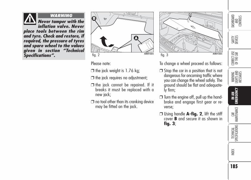
185
SAFE
TYDE
VICES
WARN
ING
LIGHT
S AN
D ME
SSAG
ES
CAR
MAIN
TENA
NCE
TECH
NICA
LSP
ECIFI
CATIO
NSIN
DEX
CORR
ECT U
SE
OF TH
E CAR
DASH
BOAR
DAN
DCO
NTRO
LS
IN A
N EM
ERGE
NCY
Please note:
❒ the jack weight is 1.76 kg;
❒ the jack requires no adjustment;
❒ the jack cannot be repaired. If itbreaks it must be replaced with anew jack;
❒ no tool other than its cranking devicemay be fitted on the jack.
To change a wheel proceed as follows:
❒ Stop the car in a position that is notdangerous for oncoming traffic whereyou can change the wheel safely. Theground should be flat and adequate-ly firm;
❒ Turn the engine off, pull up the hand-brake and engage first gear or re-verse;
❒ Using handle A-fig. 2, lift the stiffcover B and secure it as shown in fig. 3;
Never tamper with theinflation valve. Never
place tools between the rimand tyre. Check and restore, ifrequired, the pressure of tyresand spare wheel to the valuesgiven in section “TechnicalSpecifications”.
WARNING
A0E0132mfig. 2 A0E0133mfig. 3

186
SAFE
TYDE
VICES
WARN
ING
LIGHT
S AN
D ME
SSAG
ESCA
RMA
INTE
NANC
ETE
CHNI
CAL
SPEC
IFICA
TIONS
INDE
XCO
RREC
T USE
OF
THE C
AR
DASH
BOAR
DAN
DCO
NTRO
LSIN
AN
EMER
GENC
Y
❒ Loosen the bolts of the wheel to bereplaced by about one turn with thewrench provided A-fig. 5; if the caris fitted with alloy rims, shake the carto facilitate removing this rim fromthe wheel hub;
❒ Remove the wheel cap A-fig. 6(only versions with steel rims);
❒ Take out the tool container fig. 4;
A0E0134mfig. 4 A0E0206mfig. 5 A0E0207mfig. 6

187
SAFE
TYDE
VICES
WARN
ING
LIGHT
S AN
D ME
SSAG
ES
CAR
MAIN
TENA
NCE
TECH
NICA
LSP
ECIFI
CATIO
NSIN
DEX
CORR
ECT U
SE
OF TH
E CAR
DASH
BOAR
DAN
DCO
NTRO
LS
IN A
N EM
ERGE
NCY
❒ Fit the handle L-fig. 9 to operatethe jack and lift the car until thewheel to be changed is several cen-timetres off the ground;
❒ Operate the device F-fig. 9 to ex-tend the jack until the top of the jackG fits correctly into catch H;
A0E0208mfig. 9A0E0195mfig. 7
A0E0049mfig. 8
❒ The jack shall be fitted as shown infig. 7 (for versions fitted withsideskirts, before fitting the jack, re-move cover A-fig. 8 set on thesideskirt as shown in the figure);
❒ Warn anybody nearby that the car isabout to be lifted. They must stayclear and not touch the car until itis back on the ground;

188
SAFE
TYDE
VICES
WARN
ING
LIGHT
S AN
D ME
SSAG
ESCA
RMA
INTE
NANC
ETE
CHNI
CAL
SPEC
IFICA
TIONS
INDE
XCO
RREC
T USE
OF
THE C
AR
DASH
BOAR
DAN
DCO
NTRO
LSIN
AN
EMER
GENC
Y
❒ fit the space-saver spare wheel mak-ing one of the holes A-fig. 10 co-incide with the relevant pin B;
❒ Using the wrench provided, fully tight-en the five fastening bolts;
❒ Lower the car and remove the jack;
❒ Use the wrench provided to fastenthe bolts completely in a criss-crossfashion according to the sequenceshown in fig. 11.
❒ Loosen the fastening bolts and thenremove the wheel;
❒ Make sure the contact surfaces be-tween space-saver spare wheel andhub are clean so that the fasteningbolts will not come loose;
A0E0210mfig. 11A0E0209mfig. 10

189
SAFE
TYDE
VICES
WARN
ING
LIGHT
S AN
D ME
SSAG
ES
CAR
MAIN
TENA
NCE
TECH
NICA
LSP
ECIFI
CATIO
NSIN
DEX
CORR
ECT U
SE
OF TH
E CAR
DASH
BOAR
DAN
DCO
NTRO
LS
IN A
N EM
ERGE
NCY
REFITTING A NORMAL WHEEL
Following the procedure described pre-viously, raise the car and remove thespare wheel.
Versions with steel rims
Proceed as follows:❒ Make sure the contact surfaces be-
tween standard wheel and hub areclean so that the fastening bolts will notcome loose;
❒ Fit the standard wheel taking into ac-count that pin B-fig. 10 shall coin-cide with one of the holes A;
❒ Place the wheel cap on the wheel rimmaking symbol C, (marked inside thewheel cap), coincide with the inflationvalve fig. 12;
❒ Using the wrench provided, tighten thefastening bolts;
❒ Lower the car and remove the jack;❒ Using the wrench provided, fully tight-
en the bolts in the sequence shownin fig. 11;
A0E0211mfig. 13
Versions with alloy rims
Proceed as follows:
❒ tighten pin A-fig. 13 in one of theholes of the wheel hub fasteningbolts;
❒ insert the wheel on the pin and, us-ing the wrench provided, tighten thefour bolts available;
❒ loosen pin A-fig. 13 and tightenthe last fastening bolt;
❒ lower the car and remove the jack,then, using the wrench provided tight-en the bolts according to the sequencepreviously shown for the space-saverspare wheel fig. 11.
When you have finished:❒ Stow the spare wheel in the space
provided in the boot;❒ Fit the jack partially open in its con-
tainer forcing it lightly to prevent itfrom vibrating when travelling;
❒ Put the tools back into their places inthe container;
❒ Arrange the container complete withtools on the space-saver spare wheel;
❒ Reposition properly the boot stiff cov-ering.
A0E0236mfig. 12

190
SAFE
TYDE
VICES
WARN
ING
LIGHT
S AN
D ME
SSAG
ESCA
RMA
INTE
NANC
ETE
CHNI
CAL
SPEC
IFICA
TIONS
INDE
XCO
RREC
T USE
OF
THE C
AR
DASH
BOAR
DAN
DCO
NTRO
LSIN
AN
EMER
GENC
Y
The quick tyre repair kit includes:❒ a bottle A-fig. 14 containing the
sealer, fitted with:- filling pipe B- sticker C bearing the notice “max.80 km/h”, to be placed in a posi-tion visible to the driver (on the in-strument panel) after fixing the tyre;
❒ compressor D with pressure gaugeand fittings;
QUICK TYRE REPAIRKIT FIX&GOautomatic
The car is provided with the quick tyrerepair kit “FIX&GO automatic”, insteadof the traditional tool kit and space-saverspare wheel.
The kit fig. 14 is placed in the boot. Inthis container are also housed the screw-driver and the tow hitch.
A0E0114mfig. 14 A0E0048mfig. 15
❒ instruction brochure fig. 15, to beused for prompt and proper use of thequick repair kit and to be then hand-ed to the personnel charged with han-dling the tyre treated with the tyre re-pair kit;
❒ a pair of protection gloves located inthe side space of the compressor;
❒ adapters for inflating different ele-ments.
191
SAFE
TYDE
VICES
WARN
ING
LIGHT
S AN
D ME
SSAG
ES
CAR
MAIN
TENA
NCE
TECH
NICA
LSP
ECIFI
CATIO
NSIN
DEX
CORR
ECT U
SE
OF TH
E CAR
DASH
BOAR
DAN
DCO
NTRO
LS
IN A
N EM
ERGE
NCY
The cylinder containsethylene glycol. The
cylinder contains latex: it cancause allergic reactions. It isharmful if ingested or inhaledand irritant for the eyes and incase of contact. In case of con-tact rinse immediately withwater and take off contami-nated clothes. If swallowed,do not induce vomit, rinse outthe mouth, drink a lot of wa-ter and call the doctor imme-diately. Keep away from chil-dren. This product must not beused by asthmatics. Do not in-hale vapours. Call the doctorimmediately in case of aller-gic reactions. Keep the cylin-der in the space provided forthe purpose and far from heat.The sealing fluid has limitedlife.
WARNINGIt should be noticed that:
The sealing fluid of the quick tyre re-pair kit is effective with external tem-peratures between –20°C and +50°C.The sealing fluid has limited life.
Hand the instructionbrochure to the per-
sonnel charged with treatingthe tyre repaired with the kit.
WARNING
In the event of a punc-ture caused by foreignbodies, it is possible to
repair tyres showing damageson the track or shoulder up tomax 4 mm diameter.
Holes and damages onthe tyre side walls can-
not be repaired. Do not use thequick tyre repair kit if damag-ing is due to running with flattyre.
WARNING
Repairs are not possi-ble in case of damages
on the wheel rim (bad groovedistortion causing air loss). Donot remove foreign bodies(screws or nails) from thetyre.
WARNING

192
SAFE
TYDE
VICES
WARN
ING
LIGHT
S AN
D ME
SSAG
ESCA
RMA
INTE
NANC
ETE
CHNI
CAL
SPEC
IFICA
TIONS
INDE
XCO
RREC
T USE
OF
THE C
AR
DASH
BOAR
DAN
DCO
NTRO
LSIN
AN
EMER
GENC
Y
Proceed as follows:
❒ set the wheel to be repaired withvalve A-fig. 16 in the positionshown in the figure, then pull upthe handbrake, take the quicktyre repair kit and put it on theground near the wheel to be repaired;
❒ loosen tyre inflation valve cap, takeout the filler hose A-fig. 17 andscrew the ring nut B-fig. 18 on thetyre valve;
A0E0116mfig. 17
A0E0214mfig. 18
INFLATING PROCEDURE
A0E0212mfig. 16
Put on the protectiongloves provided to-
gether with quick tyre repairkit.
WARNING
The compressor shallnot be operated for
more than 20 minutes. Risk ofoverheating!. Tyres repairedwith the quick tyre repair kitshall be used temporarily only.
WARNING
Replace the cylinder ifsealer has run out. Donot throw away the
cylinder and the sealing fluid.Have the sealing fluid and thecylinder disposed of in compli-ance with national and local reg-ulations.

193
SAFE
TYDE
VICES
WARN
ING
LIGHT
S AN
D ME
SSAG
ES
CAR
MAIN
TENA
NCE
TECH
NICA
LSP
ECIFI
CATIO
NSIN
DEX
CORR
ECT U
SE
OF TH
E CAR
DASH
BOAR
DAN
DCO
NTRO
LS
IN A
N EM
ERGE
NCY
❒ after reaching the tyre pressure spec-ified in paragraph “Wheels” in sec-tion “Technical Specifications”, startdriving immediately;
❒ if after 5 minutes it is still impossi-ble to reach at least 1.5 bar, disen-gage compressor from valve and cur-rent outlet, then move the car forthfor approx. 10 metres in order to dis-tribute the sealing fluid inside the tyreevenly, then repeat the inflation op-eration;
❒ If after this operation it is still im-possible after 5 minutes to reach atleast 1.8 bar, do start driving sincethe tyre is excessively damaged andthe quick tyre repair kit cannot guar-antee suitable sealing, contact AlfaRomeo Authorized Services;
❒ make sure the compressor switch A-fig. 19 is set to 0 (off), start theengine and fit plug A-fig. 20 intothe outlet/cigar lighter on the frontconsole and then turn on the com-pressor by setting switch A-fig. 19to I (on);
❒ Inflate the tyre to the pressure speci-fied in paragraph “Wheels” in section“Technical Specifications”. Check tyrepressure on gauge B-fig. 19 withcompressor off to obtain precise read-ing;
A0E0213mfig. 19 A0E0217mfig. 20Apply the sticker in avisible position for the
driver to indicate that the tyrehas been treated with thequick tyre repair kit. Drivecarefully especially when cor-nering and do not exceed 80km/h. Avoid heavy brakingand accelerating.
WARNING

194
SAFE
TYDE
VICES
WARN
ING
LIGHT
S AN
D ME
SSAG
ESCA
RMA
INTE
NANC
ETE
CHNI
CAL
SPEC
IFICA
TIONS
INDE
XCO
RREC
T USE
OF
THE C
AR
DASH
BOAR
DAN
DCO
NTRO
LSIN
AN
EMER
GENC
Y
You shall absolutelycommunicate that the
tyre has been repaired withthe quick tyre repair kit. Handthe instruction brochure to thepersonnel charged with treat-ing the tyre repaired with thekit.
WARNING
A0E0215mfig. 21
A0E0216mfig. 22
CHECKING AND RESTORINGPRESSURE ONLY
The compressor can be also used just forrestoring pressure. Disconnect the quickconnection A-fig. 21 and connect itdirectly to the tyre valve fig. 22; in thisway the cylinder is not connected tocompressor and the sealing fluid will notflow into the tyre.
If pressure falls below1.8 bar, stop the car
since the tyre is excessivelydamaged and the quick tyrerepair kit Fix & Go automaticcannot guarantee suitablesealing, contact Alfa RomeoAuthorized Services.
WARNING
❒ after driving for about 10 minutesstop and check again the tyre pres-sure; pull up the handbrake;
❒ if at least 1.8 bar pressure is read, re-store proper pressure (with enginerunning and handbrake on) andrestart;
❒ drive with the utmost care to thenearest Alfa Romeo Authorized Service.
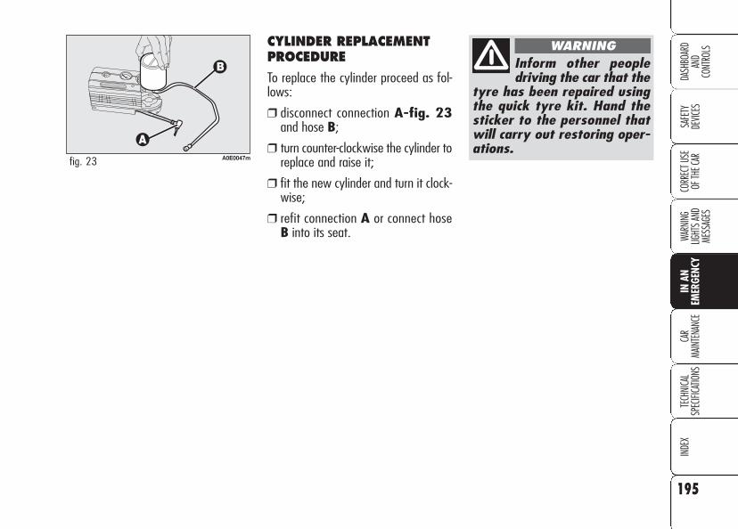
195
SAFE
TYDE
VICES
WARN
ING
LIGHT
S AN
D ME
SSAG
ES
CAR
MAIN
TENA
NCE
TECH
NICA
LSP
ECIFI
CATIO
NSIN
DEX
CORR
ECT U
SE
OF TH
E CAR
DASH
BOAR
DAN
DCO
NTRO
LS
IN A
N EM
ERGE
NCY
CYLINDER REPLACEMENTPROCEDURE
To replace the cylinder proceed as fol-lows:
❒ disconnect connection A-fig. 23and hose B;
❒ turn counter-clockwise the cylinder toreplace and raise it;
❒ fit the new cylinder and turn it clock-wise;
❒ refit connection A or connect hoseB into its seat.
A0E0047mfig. 23
Inform other peopledriving the car that the
tyre has been repaired usingthe quick tyre kit. Hand thesticker to the personnel thatwill carry out restoring oper-ations.
WARNING

196
SAFE
TYDE
VICES
WARN
ING
LIGHT
S AN
D ME
SSAG
ESCA
RMA
INTE
NANC
ETE
CHNI
CAL
SPEC
IFICA
TIONS
INDE
XCO
RREC
T USE
OF
THE C
AR
DASH
BOAR
DAN
DCO
NTRO
LSIN
AN
EMER
GENC
Y
GENERAL INSTRUCTIONS
❒ When a light is not working, checkthat the corresponding fuse is intactbefore changing a bulb. For the lo-cation of fuses, refer to the paragraph“If a fuse blows” in this section;
❒ Before changing a bulb check the con-tacts for oxidation;
❒ Burnt bulbs must be replaced by oth-ers of the same type and power;
❒ Always check the height of the head-light beam after changing a bulb.
IMPORTANT The headlight inner sur-face may be lightly misted over: this isnot a fault but a natural fact due to lowtemperature and the level of air humid-ity. It will disappear as soon the head-lights are turned on. The presence ofdrops inside the headlights means wa-ter infiltration, therefore contact AlfaRomeo Authorized Services.
WHEN NEEDING TO CHANGE A BULB
Modifications or re-pairs to the electrical
system (electronic controlunits) carried out incorrectlyand without bearing the fea-tures of the system in mindcan cause malfunctions withthe risk of fire.
WARNING
Due to high voltage,the bulb of (Bixenon)
gas-discharge headlights mustonly be replaced by experts:danger of death! Contact AlfaRomeo Authorized Services.
WARNING
Halogen bulbs containpressurised gas which,
if broken, may cause smallfragments of glass to be pro-jected outwards.
WARNING
Halogen bulbs must behandled touching only
the metallic part. If the trans-parent bulb is touched with thefingers, its lighting intensity isreduced and life of the bulbmay be compromised. Iftouched accidentally, rub thebulb with a cloth moistenedwith alcohol and allow to dry.
WARNING

197
SAFE
TYDE
VICES
WARN
ING
LIGHT
S AN
D ME
SSAG
ES
CAR
MAIN
TENA
NCE
TECH
NICA
LSP
ECIFI
CATIO
NSIN
DEX
CORR
ECT U
SE
OF TH
E CAR
DASH
BOAR
DAN
DCO
NTRO
LS
IN A
N EM
ERGE
NCY
B Bayonet type bulbs: press thebulb, turn counter-clockwise to re-move this type of bulb from itsholder.
C Tubular bulbs: release themfrom their contacts to remove.
D-E Halogen bulbs: to remove thebulb, release the clip holding thebulb in place.
F Gas-discharge bulbs(Bixenon).
TYPES OF BULBS fig. 24
Various types of bulbs are fitted to yourcar:
A Glass bulbs: clipped into posi-tion. Pull to remove.
A0E0117mfig. 24

198
SAFE
TYDE
VICES
WARN
ING
LIGHT
S AN
D ME
SSAG
ESCA
RMA
INTE
NANC
ETE
CHNI
CAL
SPEC
IFICA
TIONS
INDE
XCO
RREC
T USE
OF
THE C
AR
DASH
BOAR
DAN
DCO
NTRO
LSIN
AN
EMER
GENC
YBULBS FIGURE 24 TYPE POWER
Main beam headlights D H7 55W
Dipped beam headlights D H7 55W
Main beams/Dipped beams (versions with Bixenon headlights) (where provided) F D1S 55W
Additional main beams (where provided) D H1 55W
Front sidelights (1 per headlight) A W5WB 5W
Taillights (1 on fixed light unit - 1 on mobile light unit) B P21/5W 5W
Front fog lights E H7 55W
Front direction indicator B PY21W 21W
Side direction indicator A W5W 5W
Rear direction indicator B P21W 21W
Brake lights B P21/5W 21W
Third brake light A W2,3W 2,3W
Reversing light B P21W 21W
Rear fog lights B P21W 21W
Number plate lights A W5W 5W
Front ceiling light 2xA+1C 2xW5+10W 5+5+10W
Boot light C 10W 10W
Rear ceiling light A 2xW5W 5+5W
Courtesy mirror lights A 1,5W 1.5W
Glovebox light A W5W 5W
Puddle/door lights A W5W 5W

199
SAFE
TYDE
VICES
WARN
ING
LIGHT
S AN
D ME
SSAG
ES
CAR
MAIN
TENA
NCE
TECH
NICA
LSP
ECIFI
CATIO
NSIN
DEX
CORR
ECT U
SE
OF TH
E CAR
DASH
BOAR
DAN
DCO
NTRO
LS
IN A
N EM
ERGE
NCY
Main beam headlights (halogen bulbs)
To change the bulb, proceed as follows:
❒ remove cover A-fig. 25 by turningit counter-clockwise;
❒ disconnect the electric connector A-fig. 25;
❒ release the bulb holder catch B;
IF AN EXTERIORLIGHT BURNS OUT
For the type of bulb and power rating,see “When needing to change a bulb”.
FRONT LIGHT UNITS
The front light units contain main beam,sidelights, direction indicator and dippedbeam bulbs.
To change the bulbs, turn cap counter-clockwise and then remove it.
The bulbs are arranged inside the lightunit fig. 25 as follows:
A Main beam headlights
B Sidelights/direction indicators
C Dipped beam headlights
A0E0191mfig. 25
After replacement, re-fit the covers correctly
checking that they are proper-ly secured.
WARNING
A0E0223mfig. 26
❒ remove the bulb and replace it;
❒ fit the new bulb and refit bulb hold-er catch B-fig. 26;
❒ reconnect the electrical connector A;
❒ refit the protective cover properly.

200
SAFE
TYDE
VICES
WARN
ING
LIGHT
S AN
D ME
SSAG
ESCA
RMA
INTE
NANC
ETE
CHNI
CAL
SPEC
IFICA
TIONS
INDE
XCO
RREC
T USE
OF
THE C
AR
DASH
BOAR
DAN
DCO
NTRO
LSIN
AN
EMER
GENC
Y
Sidelights
To change the bulb, proceed as follows:
❒ turn cover B-fig. 25 counter-clock-wise;
❒ press tab A-fig. 27, remove thebulb and replace it;
❒ refit the bulb holder, it shall click in-to place; look at the light from theoutside to check for proper bulb po-sitioning;
❒ refit the protective cover properly.
A0E0193mfig. 27 A0E0194mfig. 28 A0E0192mfig. 29
Front direction indicators
To change the bulb, proceed as follows:
❒ turn cover B-fig. 25 counter-clock-wise;
❒ turn the bulb holder A-fig. 28 coun-terclockwise, remove the bulb and re-place it;
❒ refit the bulb holder, it shall click intoplace; look at the light from the out-side to check for proper bulb position-ing;
❒ refit the protective cover properly.
Dipped beam headlights (halogen bulbs)
To change the bulb, proceed as follows:
❒ turn cover C-fig. 25 counter-clock-wise;
❒ disconnect the electric connector A-fig. 29;
❒ release the bulb holder catch B;
❒ remove the bulb and replace it;
❒ fit the new bulb and refit bulb holdercatch B-fig. 29;

201
SAFE
TYDE
VICES
WARN
ING
LIGHT
S AN
D ME
SSAG
ES
CAR
MAIN
TENA
NCE
TECH
NICA
LSP
ECIFI
CATIO
NSIN
DEX
CORR
ECT U
SE
OF TH
E CAR
DASH
BOAR
DAN
DCO
NTRO
LS
IN A
N EM
ERGE
NCY
Side direction indicators
To change the bulb, proceed as follows:
❒ push the lens by hand in opposite run-ning direction in order to press thecatch A-fig. 30. Release the frontpart and remove the unit;
❒ turn the bulb holder B-fig. 31 coun-terclockwise and remove it from lensC.
❒ remove bulb D and replace it;
❒ fit the bulb holder B into the lens Cthen position the unit, the catch shallclick into place A-fig. 30.
Front fog lights fig. 32(where provided)
IMPORTANT Contact Alfa Romeo Au-thorized Services to have front fog lightsreplaced and adjusted.
A0E0163mfig. 30 A0E0164mfig. 31
Be careful not to dam-age the car body or thelens.
A0E0196mfig. 32
Due to high voltage,the bulb of (Bixenon)
gas-discharge headlights mustonly be replaced by experts:danger of death! Contact AlfaRomeo Authorized Services.
WARNING
Gas-discharge dippedbeam/main beam headlights(Bixenon) (where provided)

202
SAFE
TYDE
VICES
WARN
ING
LIGHT
S AN
D ME
SSAG
ESCA
RMA
INTE
NANC
ETE
CHNI
CAL
SPEC
IFICA
TIONS
INDE
XCO
RREC
T USE
OF
THE C
AR
DASH
BOAR
DAN
DCO
NTRO
LSIN
AN
EMER
GENC
Y
Reversing light/rear foglights
To replace the bulbs proceed as follows:
❒ open the tailgate;
❒ turn device A-fig. 33 to open lidB;
❒ lower the lid and remove the bulbholder unit by pressing the retaining tabsC-fig. 34;
❒ remove and replace the burnt-outbulb by pressing it slightly and turn-ing it counterclockwise fig. 35:
D: reversing light bulb on passengerside (or right side);
D: reversing light bulb on driver side (orleft side)
❒ refit the bulb holder unit securing itproperly using the retaining tabs C-fig. 34;
❒ close lid B-fig. 33.
REAR LIGHT UNITS
Rear light units contain: reversing light,rear fog light, direction indicators, tail-lights, number plate lights, brake lightand third brake light bulbs.
A0E0165mfig. 33 A0E0166mfig. 34 A0E0167mfig. 35

203
SAFE
TYDE
VICES
WARN
ING
LIGHT
S AN
D ME
SSAG
ES
CAR
MAIN
TENA
NCE
TECH
NICA
LSP
ECIFI
CATIO
NSIN
DEX
CORR
ECT U
SE
OF TH
E CAR
DASH
BOAR
DAN
DCO
NTRO
LS
IN A
N EM
ERGE
NCY
Direction indicators/Taillights/Brake lights
To replace the bulbs proceed as follows:
❒ open the tailgate;
❒ loosen screw A-fig. 37 and removethe protection cover B;
❒ remove the bulb holder unit C-fig. 38 by pressing the retainingtabs D.
A0E0170mfig. 37
Taillight bulb on tailgate
To replace the bulbs proceed as follows:
❒ open the tailgate;
❒ turn device A-fig. 33 to open lidB;
❒ lower the lid and remove the bulbholder unit by pressing the retainingtabs C-fig. 34;
A0E0229mfig. 36
❒ remove and replace the burnt-outbulb by pressing it slightly and turn-ing it counterclockwise fig. 36:
D: taillight bulb on right/left headlight
❒ refit the bulb holder unit securing itproperly using the retaining tabs C-fig. 34;
❒ close lid B-fig. 33.
A0E0040mfig. 38

204
SAFE
TYDE
VICES
WARN
ING
LIGHT
S AN
D ME
SSAG
ESCA
RMA
INTE
NANC
ETE
CHNI
CAL
SPEC
IFICA
TIONS
INDE
XCO
RREC
T USE
OF
THE C
AR
DASH
BOAR
DAN
DCO
NTRO
LSIN
AN
EMER
GENC
Y
Additional brake light (third stop)
Contact Alfa Romeo Authorized Servicesto have the third brake light replaced.
❒ remove and replace the burnt-outbulb by pressing it slightly and turn-ing it counter-clockwise fig. 39:
E taillight/brake light bulb;
F direction indicator bulb.
❒ refit the bulb holder unit securing itproperly using the retaining tabs D-fig. 38;
❒ refit the protection cover B-fig. 37and tighten screw A.
Number plate light
To replace the bulbs proceed as follows:
❒ operate with a flat blade screwdriver pro-tected by a soft cloth on device A-fig.40 to remove the light unit B;
❒ remove the bulb holder C-fig. 41 byturning it slightly and replace the snap-fitted bulb D.
A0E0041mfig. 39 A0E0168mfig. 40 A0E0169mfig. 41

205
SAFE
TYDE
VICES
WARN
ING
LIGHT
S AN
D ME
SSAG
ES
CAR
MAIN
TENA
NCE
TECH
NICA
LSP
ECIFI
CATIO
NSIN
DEX
CORR
ECT U
SE
OF TH
E CAR
DASH
BOAR
DAN
DCO
NTRO
LS
IN A
N EM
ERGE
NCY
IF AN INTERIORLIGHT BURNS OUT
For the type of bulb and power rating,see “When needing to change a bulb”.
FRONT CEILING LIGHT
Contact Alfa Romeo Authorized Servicesto change the bulb.
❒ turn the 2 bulb holders A-fig. 43counter-clockwise, remove and re-place bulbs.
A0E0183mfig. 42 A0E0084mfig. 43
REAR CEILING LIGHT
Versions without sunroofTo change the bulb, proceed as follows:
❒ remove the front ceiling light work-ing in the points shown by the arrows(see fig. 42);

206
SAFE
TYDE
VICES
WARN
ING
LIGHT
S AN
D ME
SSAG
ESCA
RMA
INTE
NANC
ETE
CHNI
CAL
SPEC
IFICA
TIONS
INDE
XCO
RREC
T USE
OF
THE C
AR
DASH
BOAR
DAN
DCO
NTRO
LSIN
AN
EMER
GENC
Y
Versions with sunroof
To replace the bulbs proceed as follows:
❒ remove the ceiling light A-fig. 44working in the points shown by the ar-rows;
❒ replace the bulb B-fig. 45 releas-ing it from the side contacts makingsure that the new bulb is correctlyclamped between the contacts.
A0E0098mfig. 44 A0E0099mfig. 45
COURTESY MIRROR LIGHTS(where provided)
To change the bulb, proceed as follows:
❒ open the mirror cover A-fig. 46;
❒ remove the bulb B levering in thepoints shown by the arrows;
A0E0118mfig. 46

207
SAFE
TYDE
VICES
WARN
ING
LIGHT
S AN
D ME
SSAG
ES
CAR
MAIN
TENA
NCE
TECH
NICA
LSP
ECIFI
CATIO
NSIN
DEX
CORR
ECT U
SE
OF TH
E CAR
DASH
BOAR
DAN
DCO
NTRO
LS
IN A
N EM
ERGE
NCY
❒ close protection B-fig. 49 on lightunit A-fig. 48;
❒ refit the light unit inserting first oneside and then the other one untilhearing the locking click.
GLOVEBOX LIGHT
To change the bulb, proceed as follows:
❒ open the glovebox;
❒ remove the light unit A-fig. 48 lev-ering in the point shown by the ar-row;
❒ raise protection B-fig. 49 and re-place the snap-fitted bulb;
A0E0172mfig. 48 A0E0173mfig. 49
❒ replace the bulb C-fig. 47 releas-ing it from the side contacts makingsure that the new bulb is correctlyclamped between the contacts.
A0E0171mfig. 47

208
SAFE
TYDE
VICES
WARN
ING
LIGHT
S AN
D ME
SSAG
ESCA
RMA
INTE
NANC
ETE
CHNI
CAL
SPEC
IFICA
TIONS
INDE
XCO
RREC
T USE
OF
THE C
AR
DASH
BOAR
DAN
DCO
NTRO
LSIN
AN
EMER
GENC
Y
BOOT LIGHT
To change the bulb, proceed as follows:
❒ open the tailgate;
❒ remove the light unit A-fig. 50 lev-ering in the point shown by the ar-row;
❒ open the protection cover B-fig. 51and replace the bulb releasing it fromthe side contacts making sure thatthe new bulb is correctly clamped be-tween the contacts;
❒ re-close the protective cover B;
❒ refit the light unit inserting first oneside and then the other one untilhearing the locking click.
❒ close protection B-fig. 53 on lightunit A-fig. 52;
❒ refit the light unit inserting first oneside and then the other one untilhearing the locking click.
A0E0205mfig. 50 A0E0075mfig. 52A0E0204mfig. 51
PUDDLE LIGHT
To change the bulb, proceed as follows:
❒ open the door and remove lens A-fig. 52 levering in the point shownby the arrow;
❒ raise protection B-fig. 53 and re-place the snap-fitted bulb;
A0E0235mfig. 53

209
SAFE
TYDE
VICES
WARN
ING
LIGHT
S AN
D ME
SSAG
ES
CAR
MAIN
TENA
NCE
TECH
NICA
LSP
ECIFI
CATIO
NSIN
DEX
CORR
ECT U
SE
OF TH
E CAR
DASH
BOAR
DAN
DCO
NTRO
LS
IN A
N EM
ERGE
NCY
IF A FUSE BLOWS
GENERAL
The fuse is a protective device for theelectric system: it comes into action (i.e.it cuts off) mainly due to a fault or im-proper action on the system.
When a device does not work, check theefficiency of its fuse. The conductor el-ement must be intact; if not, replace thefuse with one of the same amp rating(same colour).
A: undamaged fuse
B: fuse with damaged filament.
To replace a fuse, use the pliers Chooked to the fusebox on the dash-board.
A0E0119mfig. 54
Never replace a brokenfuse with anything oth-er than a new fuse.
Never change a fusewith another with a
higher amp rating, danger offire.
WARNING
If a general fuse(MEGA-FUSE, MAXI-
FUSE) cuts in, do not attemptany repair and contact AlfaRomeo Authorized Services.Before changing a fuse, checkthe ignition key has been re-moved and that all the otherelectric devices have beenturned off/disabled.
WARNING
If the fuse blows again,contact Alfa Romeo Au-
thorized Services.
WARNING

210
SAFE
TYDE
VICES
WARN
ING
LIGHT
S AN
D ME
SSAG
ESCA
RMA
INTE
NANC
ETE
CHNI
CAL
SPEC
IFICA
TIONS
INDE
XCO
RREC
T USE
OF
THE C
AR
DASH
BOAR
DAN
DCO
NTRO
LSIN
AN
EMER
GENC
Y
FUSE LOCATION
Fuses are grouped into four fuse boxesto be found respectively on the dash-board, on the battery positive pole, nearthe battery and inside the boot (right-hand side).
Fuse box on the dashboard
To gain access to the fuses in the fusebox on the dashboard, loosen the fas-tening screw A-fig. 55 and removethe cover B.
A0E0157mfig. 55
A0E0124mfig. 56

211
SAFE
TYDE
VICES
WARN
ING
LIGHT
S AN
D ME
SSAG
ES
CAR
MAIN
TENA
NCE
TECH
NICA
LSP
ECIFI
CATIO
NSIN
DEX
CORR
ECT U
SE
OF TH
E CAR
DASH
BOAR
DAN
DCO
NTRO
LS
IN A
N EM
ERGE
NCY
Fuse box on the batterypositive pole
To gain access to the fuses in the fusebox on the battery positive pole pressthe retainers A-fig. 57 and removethe protection cover B.
A0E0126mfig. 57
A0E0125mfig. 58

212
SAFE
TYDE
VICES
WARN
ING
LIGHT
S AN
D ME
SSAG
ESCA
RMA
INTE
NANC
ETE
CHNI
CAL
SPEC
IFICA
TIONS
INDE
XCO
RREC
T USE
OF
THE C
AR
DASH
BOAR
DAN
DCO
NTRO
LSIN
AN
EMER
GENC
Y
Fuse box near the battery
To gain access to the fuses, loosen thetwo fastening screws A-fig. 59 andremove the protection cover B.
A0E0128mfig. 59
A0E0123mfig. 60

213
SAFE
TYDE
VICES
WARN
ING
LIGHT
S AN
D ME
SSAG
ES
CAR
MAIN
TENA
NCE
TECH
NICA
LSP
ECIFI
CATIO
NSIN
DEX
CORR
ECT U
SE
OF TH
E CAR
DASH
BOAR
DAN
DCO
NTRO
LS
IN A
N EM
ERGE
NCY
Fuse box in the boot (left-hand side)
To gain access to the fuses, open the lidon the left side of the boot as shown bythe arrow A-fig. 61.
A0E0129mfig. 61
A0E0224mfig. 62

214
SAFE
TYDE
VICES
WARN
ING
LIGHT
S AN
D ME
SSAG
ESCA
RMA
INTE
NANC
ETE
CHNI
CAL
SPEC
IFICA
TIONS
INDE
XCO
RREC
T USE
OF
THE C
AR
DASH
BOAR
DAN
DCO
NTRO
LSIN
AN
EMER
GENC
YFUSE SUMMARY TABLE
LIGTHS FUSE AMPERE FIGURE
Right main beam headlight F14 10 60
Left main beam headlight F15 10 60
Right dipped beam headlight F12 15 56
Left dipped beam headlight F13 15 56
Front fog light F30 15 60
Reversing light F35 7.5 56
Third brake light F37 7.5 56
Front/rear ceiling light F39 10 56
Front ceiling light F49 7.5 56
Direction indicators F53 10 56
Hazard lights F53 10 56
USERS FUSE AMPERE FIGURE
Engine compartment control unit F70 (MEGA-FUSE) 150 58
Instrument panel control unit F71 70 58
Fuel pre-heating unit (diesel versions) F73 60 58
Boot control unit F01 (MAXI-FUSE) 70 60
Instrument panel control unit F01 (MAXI-FUSE) 70 60

215
SAFE
TYDE
VICES
WARN
ING
LIGHT
S AN
D ME
SSAG
ES
CAR
MAIN
TENA
NCE
TECH
NICA
LSP
ECIFI
CATIO
NSIN
DEX
CORR
ECT U
SE
OF TH
E CAR
DASH
BOAR
DAN
DCO
NTRO
LS
IN A
N EM
ERGE
NCY
USERS FUSE AMPERE FIGURE
Climate control system fan F02 (MAXI-FUSE) 40 60
Electric steering lock F03 (MAXI-FUSE) 20 60
Brake branch point (pump) F04 (MAXI-FUSE) 40 60
Brake branch point (solenoid valve) F05 (MAXI-FUSE) 40 60
Radiator fan (low speed) F06 (MAXI-FUSE) 40 60
Radiator fan (high speed) F07 (MAXI-FUSE) 50 60
Headlight washer F09 20 60
Horns F10 15 60
Electronic injection sundry secondary services F11 15 60
+ INT for electronic injection system F16 7.5 60
Electronic injection primary services F17 10 60
Engine control branch point F18 15 60
Climate control system compressor F19 7.5 60
Rear window heating F20 20 60
Fuel pump supply F21 20 60
Ignition coils/injectors (petrol versions) F22 15 60
Electronic injection primary services diesel versions) F22 20 60
Sound system/radionavigation system power F23 15 60
Body Computer branch point/Headlight washer relay coil F31 7.5 56
Driver’s door branch point/passenger’s door branch point/ignition device F32 15 56
Rear left power window F33 20 56
Rear right power window F34 20 56

216
SAFE
TYDE
VICES
WARN
ING
LIGHT
S AN
D ME
SSAG
ESCA
RMA
INTE
NANC
ETE
CHNI
CAL
SPEC
IFICA
TIONS
INDE
XCO
RREC
T USE
OF
THE C
AR
DASH
BOAR
DAN
DCO
NTRO
LSIN
AN
EMER
GENC
YUSERS FUSE AMPERE FIGURE
Water in diesel fuel filter sensor/flow meter F35 7.5 56
Brake light switch/central console control panel F35 7.5 56
Cruise Control F35 7.5 56
AQS sensor F35 7.5 56
Boot branch point/front door branch point power F36 20 56
Instrument panel branch point F37 7.5 56
Front headlight control unit/Power to control unit for gas-dischargeheadights (Bixenon) (where provided) F37 7.5 56
Boot locking/unlocking gearmotor F38 15 56
EOBD system diagnostic socket F39 10 56
T.P.M.S. control unit F39 10 56
Mobile phone presetting F39 10 56
Alarm system control unit (where provided) F39 10 56
Climate control system F39 10 56
Heated rear window F40 30 56
Windscreen washer/rear window washer nozzle demister F41 7.5 56
Heated mirror demister F41 7.5 56
Brake branch point power (ABS/VDC) – Steering angle branch point – Yawing sensor F42 7.5 56
Windscreen wiper/washer F43 30 56

217
SAFE
TYDE
VICES
WARN
ING
LIGHT
S AN
D ME
SSAG
ES
CAR
MAIN
TENA
NCE
TECH
NICA
LSP
ECIFI
CATIO
NSIN
DEX
CORR
ECT U
SE
OF TH
E CAR
DASH
BOAR
DAN
DCO
NTRO
LS
IN A
N EM
ERGE
NCY
USERS FUSE AMPERE FIGURE
Front cigar lighter on central console F44 10 56
Sunroof control unit (curtain) F45 15 56
Sunroof F46 20 56
Left front power window F47 20 56
Right front power window/passenger’s door control unit F48 30 56
Radionavigation system F49 7.5 56
Rain sensor control unit F49 7.5 56
Steering wheel branch point F49 7.5 56
Sunroof F49 7.5 56
Control buttons panel F49 7.5 56
Volumetric alarm control unit F49 7.5 56
Parking sensor branch point F49 7.5 56
Central console button panel F49 7.5 56
Front seat controls light F49 7.5 56
Windscreen services F49 7.5 56
Mobile phone presetting F39 10 56
START/STOP button F49 7.5 56
Air Bag system F50 7.5 56
Tyer pressure monitoring system control unit F51 7.5 56

218
SAFE
TYDE
VICES
WARN
ING
LIGHT
S AN
D ME
SSAG
ESCA
RMA
INTE
NANC
ETE
CHNI
CAL
SPEC
IFICA
TIONS
INDE
XCO
RREC
T USE
OF
THE C
AR
DASH
BOAR
DAN
DCO
NTRO
LSIN
AN
EMER
GENC
YUSERS FUSE AMPERE FIGURE
Sound system presetting F51 7.5 56
Rear window washer/wiper F52 15 56
Rear cigar lighter F52 15 56
Instrument panel branch point F53 10 56
Sound system amplifier with DSP F54 30 62
Front left seat movement control F56 25 62
Driver’s seat warming left F57 7.5 62
Front right seat movement control F60 25 62
Amplifier on rear parcel shelf F61 15 62
Front passenger’ seat warming right F67 7.5 62
Free F58 --- 62
Free F58 --- 62
Free F58 --- 62
Free F58 --- 62
Free F58 --- 62
Free F58 --- 62
Free F58 --- 62
Free F58 --- 62
Free F58 --- 62
Free F58 --- 62
Free F58 --- 62
Free F80 --- 62

219
SAFE
TYDE
VICES
WARN
ING
LIGHT
S AN
D ME
SSAG
ES
CAR
MAIN
TENA
NCE
TECH
NICA
LSP
ECIFI
CATIO
NSIN
DEX
CORR
ECT U
SE
OF TH
E CAR
DASH
BOAR
DAN
DCO
NTRO
LS
IN A
N EM
ERGE
NCY
IF THE BATTERY IS FLAT
IMPORTANT The description of thebattery charging procedure is describedonly for informative purposes. This op-eration should be carried out by AlfaRomeo Authorized Services.
Charging should be slow at a low amprating for 24 hours. Charging for alonger time may damage the battery.
Charge the battery as follows:
❒ disconnect battery negative terminal(–);
❒ connect the charger cables to the bat-tery terminals, observing the poles;
❒ turn on the charger;
❒ when you have finished, turn thecharger off before disconnecting thebattery;
❒ reconnect battery negative terminal(–).
The liquid in the batteryis poisonous and corro-
sive. Do not let it touch theskin or eyes. Recharging thebattery should be done in awell ventilated area awayfrom naked flames or possiblesources of sparks: explosionand fire risk.
WARNING
Do not attempt torecharge a frozen bat-
tery. Thaw it first, otherwiseit could explode. If the batteryfroze, make sure the internalelements are not broken andthat the casing is not cracked:risk of spilling the poisonousand corrosive fluid.
WARNING

220
SAFE
TYDE
VICES
WARN
ING
LIGHT
S AN
D ME
SSAG
ESCA
RMA
INTE
NANC
ETE
CHNI
CAL
SPEC
IFICA
TIONS
INDE
XCO
RREC
T USE
OF
THE C
AR
DASH
BOAR
DAN
DCO
NTRO
LSIN
AN
EMER
GENC
YWITH THE JACK
See instructions given in paragraph“Wheel replacement” in this section
JACKING THE CAR
USING AN ARM LIFT ORWORKSHOP LIFT
Never jack the car from the front side,the car can only be jacked at the sides,jack arms or workshop lift shall beplaced as shown in fig. 63. In anycase, contact Alfa Romeo AuthorizedServices.
A0E0195mfig. 63

221
SAFE
TYDE
VICES
WARN
ING
LIGHT
S AN
D ME
SSAG
ES
CAR
MAIN
TENA
NCE
TECH
NICA
LSP
ECIFI
CATIO
NSIN
DEX
CORR
ECT U
SE
OF TH
E CAR
DASH
BOAR
DAN
DCO
NTRO
LS
IN A
N EM
ERGE
NCY
TOWING THE CAR
The tow hook provided with the car iscontained into the Fix&Go automaticcontainer.
A0E0111mfig. 64
PRECAUTIONS FORTOWING THE CAR
To prevent damaging the transmissioncomponents, tow the car only in one offollowing ways:
❒ with front wheels raised and rearwheels resting on a truck provided forthe purpose;
❒ with rear wheels raised and frontwheels resting on a truck provided forthe purpose;
❒ with front and rear wheels on theflatbed of a wrecker or maintenancevehicle.
TOW RING HOOKING
Front
Proceed as follows:
❒ take the tow hook A-fig. 64 fromthe Fix&Go automatic container.

222
SAFE
TYDE
VICES
WARN
ING
LIGHT
S AN
D ME
SSAG
ESCA
RMA
INTE
NANC
ETE
CHNI
CAL
SPEC
IFICA
TIONS
INDE
XCO
RREC
T USE
OF
THE C
AR
DASH
BOAR
DAN
DCO
NTRO
LSIN
AN
EMER
GENC
Y
Do not start the enginewhen towing the car.
WARNING
Before fitting the hook,clean accurately its
threaded seat. Before startingto tow, make sure to havetighten the hook.
WARNING
Before starting to tow,disengage the steering
lock (see paragraph “Ignition de-vice” in section “Dashboard andcontrols”). When towing, re-member that without the help ofthe brake booster and powersteering, a greater effort is re-quired on the pedal and steer-ing wheel. Do not use flexible ca-bles for towing and avoid jerks.During towing operations makesure that fastening the joint tothe car does not damage thecomponents in contact with it.When towing the car, you mustcomply with the specific trafficregulations regarding the towring and how to tow on the road.
WARNING
Rear
The tow hook A-fig. 66 for the rearbumper is fixed.
A0E0176mfig. 66
❒ remove the snap-fitted plug A-fig. 65from the front bumper. If using the flatblade screwdriver B-fig. 64 providedas standard, protect its tip with a softcloth to prevent damaging the car.
❒ tighten the tow hook in its seat.
A0E0230mfig. 65

223
SAFE
TYDE
VICES
WARN
ING
LIGHT
S AN
D ME
SSAG
ES
IN AN
EM
ERGE
NCY
TECH
NICA
LSP
ECIFI
CATIO
NSIN
DEX
CORR
ECT U
SE
OF TH
E CAR
DASH
BOAR
DAN
DCO
NTRO
LS
CAR
MAI
NTEN
ANCE
CCAARR MMAAIINNTTEENNAANNCCEESCHEDULED SERVICING....................................... 224
SERVICE SCHEDULE............................................ 225
PERIODICAL CHECKS........................................... 227
USE OF THE CAR UNDER HEAVY CONDITIONS ........ 227
CHECKING FLUID LEVELS..................................... 228
AIR FILTER/POLLEN FILTER ................................. 236
DIESEL FUEL FILTER ........................................... 236
BATTERY ........................................................... 237
WHEELS AND TYRES........................................... 241
RUBBER HOSES ................................................. 243
WINDSCREEN WIPER ......................................... 243
BODYWORK ...................................................... 245
INTERIORS ........................................................ 247
224
SAFE
TYDE
VICES
WARN
ING
LIGHT
S AN
D ME
SSAG
ESIN
AN
EMER
GENC
YTE
CHNI
CAL
SPEC
IFICA
TIONS
INDE
XCO
RREC
T USE
OF
THE C
AR
DASH
BOAR
DAN
DCO
NTRO
LSCA
RM
AINT
ENAN
CESCHEDULEDSERVICING
Correct maintenance is essential for en-suring long car life under the best condi-tions.
This is why Alfa Romeo has programmeda series of checks and maintenance op-erations every 30,000 km.
IMPORTANT At 2,000 km from thescheduled service, the display will showa dedicated message.
It is however important to remember thatscheduled servicing does not completelycover all the car’s requirements: also inthe initial period before 30,000 km ser-vice coupon and later, between onecoupon and another, ordinary care is stillrequired such as for example routinecheck and topping up the level of fluids,tyre pressure check, etc...
IMPORTANT The Programmed Main-tenance coupons are specified by theManufacturer. The failure to have themcarried out may invalidate the warranty.
Scheduled Servicing is performed by allAlfa Romeo Authorized Services, at pre-established times.
If during whatever service operation, inaddition to the ones programmed, theneed arises for further replacements orrepairs, these may be carried out onlywith the explicit agreement of the Cus-tomer.
IMPORTANT You are advised to con-tact Alfa Romeo Authorized Services inthe event of any minor operating faults,without waiting for the next servicecoupon.
If your car is used frequently for towing,the interval between one service couponand the other must be reduced.

225
SAFE
TYDE
VICES
WARN
ING
LIGHT
S AN
D ME
SSAG
ES
IN AN
EM
ERGE
NCY
TECH
NICA
LSP
ECIFI
CATIO
NSIN
DEX
CORR
ECT U
SE
OF TH
E CAR
DASH
BOAR
DAN
DCO
NTRO
LS
CAR
MAI
NTEN
ANCE
30 60 90 120 150 180
● ● ● ● ● ●
● ● ● ● ● ●
● ● ● ● ● ●
● ● ● ● ● ●
● ● ● ● ● ●
● ● ●
● ● ● ● ● ●
● ● ● ● ● ●
● ● ● ● ● ●
● ● ●
● ●
● ●
● ●
SERVICE SCHEDULE
Thousands of km
Check tyre conditions/wear and adjust pressure if required
Check light system operation (headlights, direction indicators, hazard lights, boot lights, passenger compartment lights, glovebox lights, warning lights, etc.)Check windscreen wiper/washer operation,adjust nozzles if requiredCheck windscreen/rear window blade position/wearCheck front disk brake pad conditions and wearand wear indicator operationCheck rear disk brake pad conditions and wearSight inspect the conditions of: body external parts, underbody protection, pipes and hoses (exhaust - fuel - brakes), rubber parts (boots, sleeves, bushes, etc.)Check cleanness of locks, bonnet and boot and lever cleanness and lubricationCheck and top up, if required, fluid levels(brakes/hydraulic clutch, power steering, windscreen washer, battery, engine coolant, etc.)Check and adjust handbrake lever strokeSight inspect accessory drive belt conditionsSight inspect accessory drive belt conditions (1.8 version)Sight inspect timing belt conditions (1.8 version)

226
SAFE
TYDE
VICES
WARN
ING
LIGHT
S AN
D ME
SSAG
ESIN
AN
EMER
GENC
YTE
CHNI
CAL
SPEC
IFICA
TIONS
INDE
XCO
RREC
T USE
OF
THE C
AR
DASH
BOAR
DAN
DCO
NTRO
LSCA
RM
AINT
ENAN
CEThousands of km
Check and adjust tappet clearance (1.9 JTDM 8v version)Check and adjust tappet clearance, if required (1.8 version)Check exhaust emissions (petrol versions)Check exhaust emissions/smoke (diesel versions)Check antievaporation system (petrol versions)Check engine control system operation (through diagnosis socket)Replace accessory drive belt/sReplace accessory drive belt/s (1.8 version)Replace timing belt (1.8 version) (*)Replace timing belt (diesel versions) (*)Change spark plugs (petrol versions except 1.8)Change spark plugs (1.8 version)Replace diesel fuel filter (diesel versions)Change air cleaner cartridge (petrol versions)Change air cleaner cartridge (diesel versions)Change front transmission gear oil (3.2 JTS versions)Change engine oil and oil filter (petrol versions) (or every 24 months)Change engine oil and oil filter (diesel versions)(**) (or every 24 months)Change brake fluid (or every 24 months)Change pollen filter (or every 24 months)(*) Regardless of the km covered, the timing belt shall be replaced every 4 years for particularly demanding use (cold climates, driving in the city, idling
for a long time) or in any case every 5 years.(**) Engine oil and oil filter shall actually be changed according to the conditions of use of the car and it is indicated by the relevant warning light or
message (where provided) on the instrument panel (see section “Warning lights and messages”).
30 60 90 120 150 180
● ● ●
●
● ● ● ● ● ●
● ● ● ● ● ●
● ●
● ● ● ● ● ●
●
●
●
●
●
● ● ●
● ● ●
● ● ●
● ● ● ● ● ●
●
● ● ● ● ● ●
(●) (●) (●) (●) (●) (●)● ● ●
● ● ● ● ● ●

227
SAFE
TYDE
VICES
WARN
ING
LIGHT
S AN
D ME
SSAG
ES
IN AN
EM
ERGE
NCY
TECH
NICA
LSP
ECIFI
CATIO
NSIN
DEX
CORR
ECT U
SE
OF TH
E CAR
DASH
BOAR
DAN
DCO
NTRO
LS
CAR
MAI
NTEN
ANCE
USE OF THE CARUNDER HEAVYCONDITIONS
Should prevailing use of the car be un-der one of the following specially heavyconditions:
❒ trailer or caravan towing;
❒ dusty roads;
❒ short distances (less than 7-8 km)and repeated with external temper-atures below zero;
❒ frequently idling engines or long dis-tance low speed driving (e.g.: door-to-door deliveries) or in case of a longterm inactivity;
❒ urban routes;
carry out checks more frequently thanrequired on Service Schedule:
❒ check front disk brake pad conditionsand wear;
❒ check cleanness of bonnet and bootlocks and lever cleanness and lubri-cation;
❒ sight inspect the conditions of: en-gine, gearbox, transmission, pipesand hoses (exhaust - fuel - brakes),rubber parts (boots, sleeves, bushes,etc.);
❒ check battery charge and fluid level(electrolyte);
❒ visual check on various drive belt con-ditions;
❒ change engine oil and oil filter, if re-quired;
❒ check and replace pollen filter, if re-quired;
❒ check and replace air cleaner, if re-quired.
PERIODICAL CHECKS
Every 1,000 km or before long jour-neys, check and top up if required:
❒ engine coolant fluid level;
❒ brake fluid level;
❒ windscreen washer fluid level;
❒ tyre pressure and conditions.
❒ check light system operation (head-lights, direction indicators, hazardlights, etc.);
❒ check windscreen wiper/washer op-eration and windscreen/rear windowblade position/wear;
Every 3,000 km check and top up if re-quired: engine oil level.
You are recommended to use FL Se-lenia products, designed and producedspecifically for Alfa Romeo cars (seetable “Capacities” in section “Techni-cal specifications”).

228
SAFE
TYDE
VICES
WARN
ING
LIGHT
S AN
D ME
SSAG
ESIN
AN
EMER
GENC
YTE
CHNI
CAL
SPEC
IFICA
TIONS
INDE
XCO
RREC
T USE
OF
THE C
AR
DASH
BOAR
DAN
DCO
NTRO
LSCA
RM
AINT
ENAN
CECHECKINGFLUID LEVELS
For refilling amounts refer to TechnicalSpecifications section.
1. Engine oil - 2. Battery 3. Brake fluid - 4. Windscreen washerfluid - 5. Engine coolant - 6. Power steering fluid
fig. 2 - 1.9 JTS - 2.2 JTS versions A0E0161m
Never smoke whileworking in the engine
compartment; gas and inflam-mable vapours may be pre-sent, with the risk of fire.
WARNING
When topping up takecare not to confuse thevarious types of fluids:
they are all incompatible withone another and could serious-ly damage the car. A0E0374m
fig. 1 - 1.8 version

229
SAFE
TYDE
VICES
WARN
ING
LIGHT
S AN
D ME
SSAG
ES
IN AN
EM
ERGE
NCY
TECH
NICA
LSP
ECIFI
CATIO
NSIN
DEX
CORR
ECT U
SE
OF TH
E CAR
DASH
BOAR
DAN
DCO
NTRO
LS
CAR
MAI
NTEN
ANCE
fig. 3 - 3.2 JTS versionA0E0038m
fig. 4 - 1.9 JTDM 8v - 1.9 JTDM 16v versions A0E0162m
1. Engine oil - 2. Battery 3. Brake fluid - 4. Windscreen washerfluid - 5. Engine coolant 6. Power steering fluid
1. Engine oil - 2. Battery 3. Brake fluid - 4. Windscreen washerfluid - 5. Engine coolant 6. Power steering fluid

230
SAFE
TYDE
VICES
WARN
ING
LIGHT
S AN
D ME
SSAG
ESIN
AN
EMER
GENC
YTE
CHNI
CAL
SPEC
IFICA
TIONS
INDE
XCO
RREC
T USE
OF
THE C
AR
DASH
BOAR
DAN
DCO
NTRO
LSCA
RM
AINT
ENAN
CE
fig. 5 - 2.4 JTDM version A0E0203m
1. Engine oil - 2. Battery 3. Brake fluid - 4. Windscreen washerfluid - 5. Engine coolant 6. Power steering fluid

231
SAFE
TYDE
VICES
WARN
ING
LIGHT
S AN
D ME
SSAG
ES
IN AN
EM
ERGE
NCY
TECH
NICA
LSP
ECIFI
CATIO
NSIN
DEX
CORR
ECT U
SE
OF TH
E CAR
DASH
BOAR
DAN
DCO
NTRO
LS
CAR
MAI
NTEN
ANCE
ENGINE OIL
Fig. 6: 1.8 version
Fig. 7: 1.9 JTS - 2.2 JTS versions
Fig. 8: 3.2 JTS version
Fig. 9: 1.9 JTDM 8V -1.9 JTDM 16V versions
Fig. 10: 2.4 JTDM version
Checking engine oil
Check the oil level a few minutes (about5) after the engine has stopped, withthe car parked on level ground.
Remove the dipstick A and clean it, put itback in completely, remove it and checkthat the level is within the MIN andMAX marks on the dipstick. The gap be-tween the MIN and MAX marks cor-responds to about one litre of oil.
A0E0018mfig. 7
A0E0069mfig. 8
A0E0233mfig. 9
A0E0202mfig. 10A0E0400mfig. 6

232
SAFE
TYDE
VICES
WARN
ING
LIGHT
S AN
D ME
SSAG
ESIN
AN
EMER
GENC
YTE
CHNI
CAL
SPEC
IFICA
TIONS
INDE
XCO
RREC
T USE
OF
THE C
AR
DASH
BOAR
DAN
DCO
NTRO
LSCA
RM
AINT
ENAN
CEEngine oil consumption
Max engine oil consumption is usually400 grams every 1000 km.
When the car is new, the engine needsto run in, therefore the engine oil con-sumption can only be considered sta-bilised after the first 5000 - 6000 km.
IMPORTANT The oil consumption de-pends on driving style and the conditionsunder which the car is used.
IMPORTANT Do not add oil withspecifications other than that alreadyin the engine.
Topping up engine oil
If the oil level is near or even below theMIN mark, add oil through the fillerneck B, until reaching the MAX mark.Oil level shall never exceed the MAXmark.
IMPORTANT If a routine check re-veals that the oil level is above theMAX mark, contact Alfa Romeo Au-thorized Services to have the correct lev-el restored.
IMPORTANT After adding or changingthe oil, let the engine turn over for a fewseconds and wait a few minutes afterturning it off before you check the level.
When the engine is hot,take care when work-
ing inside the engine compart-ment to avoid burns. Remem-ber that when the engine ishot, the fan may cut in: dangerof injury. Scarves, ties andother loose clothing might bepulled by moving parts.
WARNING
Used engine oil and fil-ter contain harmful sub-stances for the environ-
ment. Contact Alfa Romeo Au-thorized Services to have the oiland filter changed.

233
SAFE
TYDE
VICES
WARN
ING
LIGHT
S AN
D ME
SSAG
ES
IN AN
EM
ERGE
NCY
TECH
NICA
LSP
ECIFI
CATIO
NSIN
DEX
CORR
ECT U
SE
OF TH
E CAR
DASH
BOAR
DAN
DCO
NTRO
LS
CAR
MAI
NTEN
ANCE
ENGINE COOLANT FLUIDfig. 11
If the level is low, pour slowly a mixtureof 50% distilled water and 50%PARAFLU UP through the filler neckA.
A 50% mixture of distilled water andPARAFLU UP gives freeze protectionto –35°C.
A0E0017mfig. 11
The cooling system usesPARAFLU UP that shallbe used for topping up
and that cannot be mixed withother types of fluids. Shouldother fluids be added, do notstart the engine and contact Al-fa Romeo Authorized Servicesas soon as possible.
Do not remove thereservoir cap when the
engine is hot: you risk scaldingyourself.
WARNING
The cooling system ispressurised. If neces-
sary, replace the cap only withanother genuine one, other-wise system efficiency couldbe compromised.
WARNING
WINDSCREEN/HEADLIGHTWASHER FLUID fig. 12
To top up, remove the cap A and thenpour a mixture of water and TUTELAPROFESSIONAL SC 35, in the fol-lowing concentrations:
❒ 30% TUTELA PROFESSIONALSC 35 and 70% water in summer;
❒ 50% TUTELA PROFESSIONALSC 35 and 50% water in winter.
In case of temperatures below –20°C,use undiluted TUTELA PROFES-SIONAL SC 35.
A0E0029mfig. 12

234
SAFE
TYDE
VICES
WARN
ING
LIGHT
S AN
D ME
SSAG
ESIN
AN
EMER
GENC
YTE
CHNI
CAL
SPEC
IFICA
TIONS
INDE
XCO
RREC
T USE
OF
THE C
AR
DASH
BOAR
DAN
DCO
NTRO
LSCA
RM
AINT
ENAN
CEDo not travel with thewindscreen washer
reservoir empty. The wind-screen washer is fundamentalfor improving visibility.
WARNING
Certain commercial ad-ditives for windscreen
washers are inflammable. Theengine compartment containshot components which may setit on fire.
WARNING POWER STEERING FLUID fig. 13-14
Check that the fluid level in the reservoiris at maximum level: this operation shallbe carried out with the car on level sur-face, engine not running and cold.
Check that the fluid level is at the MAXmark on the reservoir or at the top mark(maximum level) shown on the dipstickunder the reservoir cap.
A0E0027mfig. 13 1.8 - 1.9 JTS - 2.2 JTS - 2.4 JTDM versions
A0E0234mfig. 14 3.2 JTS - 1.9 JTDM 8V -1.9 JTDM 16V versions
If the fluid level in the reservoir is belowthe specified level, top up as follows:
❒ start the engine and wait until the flu-id level in the reservoir has stabilized;
❒ with the engine started, turn repeat-edly the steering wheel fully right-wards and leftwards;
❒ top up until reaching the MAX markthen refit the cap.

235
SAFE
TYDE
VICES
WARN
ING
LIGHT
S AN
D ME
SSAG
ES
IN AN
EM
ERGE
NCY
TECH
NICA
LSP
ECIFI
CATIO
NSIN
DEX
CORR
ECT U
SE
OF TH
E CAR
DASH
BOAR
DAN
DCO
NTRO
LS
CAR
MAI
NTEN
ANCE
IMPORTANT For this operation it ishowever recommended to always con-tact Alfa Romeo Authorized Services.
Do not allow the pow-er steering fluid to
touch the hot parts of the en-gine: it is inflammable.
WARNING
BRAKE FLUID fig. 15
Check that the fluid level in the reservoiris at maximum. Top up with the brakefluid specified in the table “Fluids andlubricants” (see section “Technical Spec-ifications ").
NOTE Clean accurately the tank cap Aand the surrounding surface. Whenopening the cap take the utmost care toprevent impurities entering the tank.When topping up, always use a funnelwith built-in filter with mesh equal toor lower than 0.12 mm.
A0E0016mfig. 15
Make sure that the high-ly corrosive brake fluiddoes not drip onto the
paintwork. If it does, wash it offimmediately with water.
IMPORTANT For this operation it ishowever recommended to contact AlfaRomeo Authorised Services.
From time to time, check the instrumentpanel warning light x: pressing on capA (with key fitted into the ignition de-vice) the warning light shall turn on.
IMPORTANT Brake fluid absorbsmoisture. For this reason, if the car ismainly used in areas with a high degreeof atmospheric humidity, the fluid shouldbe replaced at more frequent intervalsthan specified in the Service schedule.

236
SAFE
TYDE
VICES
WARN
ING
LIGHT
S AN
D ME
SSAG
ESIN
AN
EMER
GENC
YTE
CHNI
CAL
SPEC
IFICA
TIONS
INDE
XCO
RREC
T USE
OF
THE C
AR
DASH
BOAR
DAN
DCO
NTRO
LSCA
RM
AINT
ENAN
CEBrake fluid is poisonousand highly corrosive. In
the event of accidental contact,wash the parts involved im-mediately with neutral soapand water, then rinse thor-oughly. Call the doctor imme-diately if the fluid is swal-lowed.
WARNING
Symbol π on the con-tainer indicates syn-
thetic brake fluid, distinguish-ing it from the mineral kind.Using mineral fluids irre-versibly damages the specialbraking system rubber seals.
WARNING
AIR FILTER/POLLEN FILTER
Air cleaner or pollen filter replacementshall be carried out at Alfa Romeo Au-thorized Services.
DIESEL FUEL FILTER
DRAINING THE CONDENSE
The presence of water inthe fuel circuit can se-verely damage the in-
jection system and make the en-gine misfire. If the warning lightc turns on (on certain versionstogether with a message on thedisplay) contact Alfa Romeo Au-thorized Services as soon aspossible to have the bleedingoperation carried out. Shouldthe warning light turn on afterrefuelling, water has probablybeen poured into the tank: turnthe engine off immediately andcontact Alfa Romeo AuthorizedServices.
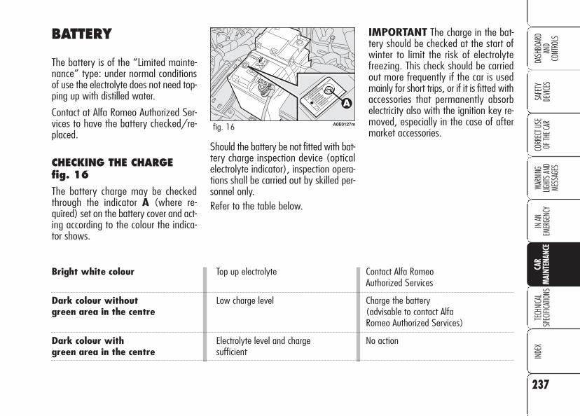
237
SAFE
TYDE
VICES
WARN
ING
LIGHT
S AN
D ME
SSAG
ES
IN AN
EM
ERGE
NCY
TECH
NICA
LSP
ECIFI
CATIO
NSIN
DEX
CORR
ECT U
SE
OF TH
E CAR
DASH
BOAR
DAN
DCO
NTRO
LS
CAR
MAI
NTEN
ANCE
BATTERY
The battery is of the “Limited mainte-nance” type: under normal conditionsof use the electrolyte does not need top-ping up with distilled water.
Contact at Alfa Romeo Authorized Ser-vices to have the battery checked/re-placed.
CHECKING THE CHARGE fig. 16
The battery charge may be checkedthrough the indicator A (where re-quired) set on the battery cover and act-ing according to the colour the indica-tor shows.
Should the battery be not fitted with bat-tery charge inspection device (opticalelectrolyte indicator), inspection opera-tions shall be carried out by skilled per-sonnel only.Refer to the table below.
A0E0127mfig. 16
Bright white colour Top up electrolyte Contact Alfa RomeoAuthorized Services
Dark colour without Low charge level Charge the batterygreen area in the centre (advisable to contact Alfa
Romeo Authorized Services)
Dark colour with Electrolyte level and charge No actiongreen area in the centre sufficient
IMPORTANT The charge in the bat-tery should be checked at the start ofwinter to limit the risk of electrolytefreezing. This check should be carriedout more frequently if the car is usedmainly for short trips, or if it is fitted withaccessories that permanently absorbelectricity also with the ignition key re-moved, especially in the case of aftermarket accessories.

238
SAFE
TYDE
VICES
WARN
ING
LIGHT
S AN
D ME
SSAG
ESIN
AN
EMER
GENC
YTE
CHNI
CAL
SPEC
IFICA
TIONS
INDE
XCO
RREC
T USE
OF
THE C
AR
DASH
BOAR
DAN
DCO
NTRO
LSCA
RM
AINT
ENAN
CEREPLACING THE BATTERY
If required, replace the battery with agenuine spare part having the samespecifications.
If a battery with different specificationsis fitted, the service intervals given inthe Service schedule in this section willno longer be valid.
Refer therefore to the instructions pro-vided by the battery manufacturer.
Incorrect fitting of elec-trical and electronic ac-cessories can seriously
damage the car. If after buyingthe car, you want to install elec-tric accessories which require per-manent electric supply (alarm,free-hand phone kit, etc.) contactAlfa Romeo Authorized Serviceswhose qualified personnel, in ad-dition to suggesting the mostsuitable devices, will evaluate theoverall electric absorption, check-ing whether the car’s electric sys-tem is capable of withstandingthe load required, or whether itshould be integrated with a morepowerful battery.
Batteries contain sub-stances that are veryharmful for the environ-
ment. You are advised to havethe battery changed at AlfaRomeo Authorized Services,which is properly equipped fordisposing of used batteries re-specting nature and the law.
The liquid in the bat-tery is poisonous and
corrosive. Avoid contact witheyes and skin. Do not bringnaked flames or possiblesources of sparks near to thebattery: risk of fire and ex-plosion.
WARNING
Running the batterywith low fluid level can
damage the battery beyondrepair and could also cause itsexplosion.
WARNING
After connecting/dis-connecting the battery,wait for 3 minutes at
least before fitting the electronickey into the ignition device inorder to allow the climate con-trol system control unit to resetthe positions of the electric ac-tuators that adjust air temper-ature and distribution.

239
SAFE
TYDE
VICES
WARN
ING
LIGHT
S AN
D ME
SSAG
ES
IN AN
EM
ERGE
NCY
TECH
NICA
LSP
ECIFI
CATIO
NSIN
DEX
CORR
ECT U
SE
OF TH
E CAR
DASH
BOAR
DAN
DCO
NTRO
LS
CAR
MAI
NTEN
ANCE
If the car is left inactivefor long periods at cold,
remove the battery and storeit in a warm place to preventfreezing.
WARNING
When working on thebattery or near it, al-
ways wear the proper gog-gles.
WARNING
USEFUL ADVICE FOR LENGTHENING THE LIFE OF YOUR BATTERY
To avoid draining your battery andlengthen its life, observe the followingindications:❒ when you park the car, ensure the
doors, tailgate and bonnet are closedproperly;
❒ the ceiling lights must be off. The caris however provided with an auto-matic system for switching off inter-nal lights;
❒ do not keep accessories (e.g.: soundsystem, hazard lights, etc.) switchedon for a long time when the engineis not running;
❒ before performing any operation onthe electrical system, disconnect thebattery negative terminal cable;
❒ battery terminals shall always be per-fectly tightened.
IMPORTANT A battery which is keptat a charge of less than 50% (optical in-dicator with dark colour without greenarea in the middle) for any length of timewill be damaged by sulphation leading toa reduction in cranking power.

240
SAFE
TYDE
VICES
WARN
ING
LIGHT
S AN
D ME
SSAG
ESIN
AN
EMER
GENC
YTE
CHNI
CAL
SPEC
IFICA
TIONS
INDE
XCO
RREC
T USE
OF
THE C
AR
DASH
BOAR
DAN
DCO
NTRO
LSCA
RM
AINT
ENAN
CEMoreover, this might lead to a higherrisk of the battery electrolyte freezing(this may even occur at –10°C). If thecar is inactive for a long period of time,refer to “Car inactivity”, in section “Cor-rect use of the car”.
In fact, since these devices continue ab-sorbing energy even when the ignitionkey is off, they gradually run down thebattery.
The total intake of these systems (factory and after-market) must be less than 0.6 mA x Ah (of the battery) as shown inthe following table:
Battery Maximum admitted stand-by intake
60 Ah 36 mA
70 Ah 42 mA
90 Ah 54 mA
If after buying the car, you want to in-stall electric accessories which requirepermanent electric supply (alarm, etc.)contact Alfa Romeo Authorized Serviceswhose qualified personnel, in additionto suggesting the most suitable devicesavailable at Lineaccessori Alfa Romeo,will evaluate the overall electric ab-sorption, checking whether the car’selectric system is capable of withstand-ing the load required, or whether itshould be integrated with a more pow-erful battery.

241
SAFE
TYDE
VICES
WARN
ING
LIGHT
S AN
D ME
SSAG
ES
IN AN
EM
ERGE
NCY
TECH
NICA
LSP
ECIFI
CATIO
NSIN
DEX
CORR
ECT U
SE
OF TH
E CAR
DASH
BOAR
DAN
DCO
NTRO
LS
CAR
MAI
NTEN
ANCE
Incorrect pressure causes abnormal tyrewear fig. 17:
A normal pressure: tread evenly worn.
B low pressure: tread particularly wornat the edges.
C high pressure: tread particularly wornin the centre.
Tyres must be replaced when the treadwears down to 1.6 mm. In any case,comply with the laws in the countrywhere the car is being driven.
IMPORTANT NOTES
As far as possible, avoid sharp brakingand screech starts, etc. Be careful not tohit the kerb, potholes or other obstacleshard. Driving for long stretches overbumpy roads can damage the tyres.
Periodically check that the tyres have nocuts in the side wall, abnormal swellingor irregular tyre wear. If any of these oc-cur, have the car seen to at Alfa RomeoAuthorized Services.
Avoid overloading the car when travel-ling: this may cause serious damage tothe wheels and tyres; if a tyre is punc-tured, stop immediately and change itto avoid damage to the tyre, the rim,suspensions and steering system.
WHEELS AND TYRES
Check the pressure of each tyre, includ-ing the space-saver spare wheel, everyfour weeks and before long journeys:pressure should be checked with the tyrerested and cold.
For the correct tyre inflation pressure,see “Wheels” in “Technical specifica-tions” section.
A0E0120mfig. 17

242
SAFE
TYDE
VICES
WARN
ING
LIGHT
S AN
D ME
SSAG
ESIN
AN
EMER
GENC
YTE
CHNI
CAL
SPEC
IFICA
TIONS
INDE
XCO
RREC
T USE
OF
THE C
AR
DASH
BOAR
DAN
DCO
NTRO
LSCA
RM
AINT
ENAN
CERemember that roadholding depends also
on the correct tyre inflatingpressure.
WARNING
If the pressure is toolow the tyre overheats
and this can cause it seriousdamage.
WARNINGNever submit alloyrims to repainting
treatments requiring to usetemperatures exceeding150°C since the mechanicalproperties of the wheels couldbe impaired.
WARNING
Do not cross switch thetyres, moving them
from the right of the car to theleft and vice versa.
WARNINGTyres age even if they are not usedmuch. Cracks in the tread rubber are asign of ageing. In any case, if the tyreshave been on the car for over 6 years,they should be checked by specialisedpersonnel, to see if they can still beused. Also remember to check the space-saver spare wheel.
In the case of replacement, always fitnew tyres, avoiding those of dubious ori-gin.
If a tyre is changed, also change the in-flation valve; to allow even wear be-tween the front and rear tyres, it is ad-visable to change them over every 10-15 thousand kilometres, keeping themon the same side of the car so as to notreverse the direction of rotation.

243
SAFE
TYDE
VICES
WARN
ING
LIGHT
S AN
D ME
SSAG
ES
IN AN
EM
ERGE
NCY
TECH
NICA
LSP
ECIFI
CATIO
NSIN
DEX
CORR
ECT U
SE
OF TH
E CAR
DASH
BOAR
DAN
DCO
NTRO
LS
CAR
MAI
NTEN
ANCE
WINDSCREEN/REARSCREEN WIPERS
BLADES
Periodically clean the rubber part usingspecial products TUTELA PROFES-SIONAL SC 35 is recommended.
If the rubber blades are bent or wornthey should be replaced. In any casethey should be changed once a year.
A few simple notions can reduce the pos-sibility of damage to the blades:
❒ if the temperature fall below zero,make sure that ice has not frozen therubber against glass. If necessary,thaw using an antifreeze product;
❒ remove any snow from the glass: inaddition to protecting the blades, thisprevents effort on the motor andoverheating;
❒ do not operate the windscreen wiperson dry glass.
RUBBER HOSES
As far as the brake system and fuel rub-ber hoses are concerned, carefully fol-low the Service schedule in this section.
Indeed ozone, high temperatures andprolonged lack of fluid in the systemmay cause hardening and cracking ofthe hoses, with possible leaks. Carefulcontrol is therefore necessary.
Driving with wornwiper blades is a seri-
ous hazard, because visibilityis reduced in bad weather.
WARNING

244
SAFE
TYDE
VICES
WARN
ING
LIGHT
S AN
D ME
SSAG
ESIN
AN
EMER
GENC
YTE
CHNI
CAL
SPEC
IFICA
TIONS
INDE
XCO
RREC
T USE
OF
THE C
AR
DASH
BOAR
DAN
DCO
NTRO
LSCA
RM
AINT
ENAN
CESPRAY NOZZLES
If the jet of fluid is missing, firstly checkthat there is fluid in the reservoir: see“Checking fluid levels” in this section).
Then check that the nozzle holes are notclogged, if necessary use a needle.
Fluid jets shall be directed at about 1/3height from the window upper edge.
HEADLIGHT WASHERS
Regularly check that the spray jets areintact and clean.
The headlight washers are automatical-ly switched on when the windscreenwasher is operated and the dippedbeams are on.
Changing the windscreenwiper blades fig. 18
How to remove the blade:
– raise the windscreen wiper arm A;
– turn the blade B by 90° around pinC, on the final section of the arm;
– remove the blade from the pin C.
How to refit the new blade:
– fit pin C into the hole in the middleof the blade B;
– refit the arm with the blade on thewindscreen.
A0E0080mfig. 18
245
SAFE
TYDE
VICES
WARN
ING
LIGHT
S AN
D ME
SSAG
ES
IN AN
EM
ERGE
NCY
TECH
NICA
LSP
ECIFI
CATIO
NSIN
DEX
CORR
ECT U
SE
OF TH
E CAR
DASH
BOAR
DAN
DCO
NTRO
LS
CAR
MAI
NTEN
ANCE
245
These include:
❒ Painting products and systems whichgive the car particular resistance tocorrosion and abrasion;
❒ Use of galvanised (or pretreated)steel sheets, with high resistance tocorrosion;
❒ Spraying of plastic parts, with a pro-tective function, in the more exposedpoints: underdoor, inner fender parts,edges, etc.;
❒ Use of “open” boxed sections to pre-vent condensation and pockets ofmoisture from triggering rust inside;
❒ use of special anti-abrasion protectivetapes in the most exposed areas(e.g.: rear mudguard, rear door,etc.).
BODY AND UNDERBODYWARRANTY
Your car is covered by warranty againstperforation due to rust of any original el-ement of the structure or body. For thegeneral terms of this warranty, refer tothe Alfa Romeo Warranty booklet.
ADVICE FOR PRESERVINGTHE BODYWORK
Paint
Paintwork does not only serve anaestethic purpose, but also protects theunderlying sheet metal.
In the case of deep scrapes or scores,you are advised to have the necessarytouching up carried out immediately toavoid the formation of rust. Use onlyoriginal paint products for touching up(see “Bodywork paint identificationplate” in section “Technical specifica-tion”).
Normal paint maintenance consists inwashing at intervals depending on theconditions and environment of use. Forexample, in highly polluted areas, or ifthe roads are sprayed with salt, it is wiseto wash the car more frequently.
BODYWORK
PROTECTION FROM ATMOSPHERIC AGENTS
The main causes of corrosion are the fol-lowing:
❒ atmospheric pollution;
❒ salty air and humidity (coastal areas,or hot humid climates);
❒ seasonal environment conditions.
Not to be underestimated is also theabrasive action of wind-borne atmos-pheric dust and sand and mud and grav-el raised by other cars.
On your car, Alfa Romeo implementedthe best manufacturing technologies toeffectively protect the bodywork againstcorrosion.

Exterior plastic parts must be cleaned inthe same way as the rest of the car.
Where possible, do not park under trees;the resinous substance many species re-lease give the paint a dull appearanceand increase the possibility of triggeringrust processes.
IMPORTANT Bird droppings must bewashed off immediately and thorough-ly as the acid they contain is particular-ly aggressive.
246
SAFE
TYDE
VICES
WARN
ING
LIGHT
S AN
D ME
SSAG
ESIN
AN
EMER
GENC
YTE
CHNI
CAL
SPEC
IFICA
TIONS
INDE
XCO
RREC
T USE
OF
THE C
AR
DASH
BOAR
DAN
DCO
NTRO
LSCA
RM
AINT
ENAN
CEWindows
Use specific window cleaner products. Usealso clean cloths to avoid scratching theglass or damaging the transparency.
IMPORTANT The inside of therearscreen should be wiped gently witha cloth in the direction of the filamentsto avoid damaging the heating device.
Front headlights
Front headlights shall be washed withsoft cloth moistened with water and cardetergent.
IMPORTANT Cleaning headlight lens-es with a dry cloth will damage theheadlights with lack of performance asa consequence. Solvents mat the lens-es with lack of performance as a con-sequence.
IMPORTANT When washing the frontheadlights with a water monitor noz-zle keep at least 2 cm away from thelenses.
To wash the car correctly proceed as fol-lows:
❒ remove the aerial from the roof toprevent damage to it if the car iswashed in an automatic system;
❒ wash the body using a low pressurejet of water;
❒ wipe a sponge with a slightly soapysolution over the bodywork, fre-quently rinsing with the sponge;
❒ rinse well with water and dry with ajet of air or a chamois leather.
When drying, take particular care withthe less visible parts like door surrounds,bonnet and around the headlights wherewater may stagnate. The car should notbe taken to a closed area immediately,but left in the open so that residual wa-ter can evaporate.
Do not wash the car after it has been leftin the sun or with the bonnet hot: thismay alter the shine of the paintwork.
Detergents cause waterpollution. Therefore thecar should be washed
in areas equipped for collectingand purifying the liquid used inthe washing process.

LEANING LEATHER SEATS
Remove dried on dirt with lightly moist-ened chamois leather or cloth withoutpressing too hard.
Remove liquid or grease stains with a dryabsorbent cloth without rubbing. Thenwipe with a soft cloth or chamois leatherwith water and neutral soap.
If the stain persists, use specific prod-ucts, carefully following the instructionsfor use.
IMPORTANT Never use spirit or al-cohol-based products.
247
SAFE
TYDE
VICES
WARN
ING
LIGHT
S AN
D ME
SSAG
ES
IN AN
EM
ERGE
NCY
TECH
NICA
LSP
ECIFI
CATIO
NSIN
DEX
CORR
ECT U
SE
OF TH
E CAR
DASH
BOAR
DAN
DCO
NTRO
LS
CAR
MAI
NTEN
ANCE
Engine compartment
At the end of the winter the engine com-partment should be carefully washed,without directing the jet against electroniccontrol units. Contact a specialised work-shop to have this done.
IMPORTANT The car should bewashed with the engine cold and the keyremoved from the ignition device. Afterwashing make sure that the various pro-tections (e.g. rubber caps and various cov-ers) have not been damaged or removed.
INTERIORS
Periodically check that water is nottrapped under the mats (due to waterdripping off shoes, umbrellas, etc.)which could cause oxidisation of thesheet metal.
CLEANING SEATS ANDFABRIC AND VELVET PARTS
Use a soft brush or vacuum cleaner toremove dust. Velvet is cleaned better ifthe brush is moistened.
Rub the seats with a sponge moistenedwith a solution of water and neutral de-tergent.

Upholstery of your carhas been designed towithstand wear deriv-
ing from common use of the car.You are however recommendedto avoid strong and/or contin-uous scratching with clothingaccessories such as metallicbuckles, studs, Velcro fasten-ings and the like, since theseitems cause circumscribed stressof the cover fabric that couldlead to yarn breaking, and dam-age the cover as a consequence.
248
SAFE
TYDE
VICES
WARN
ING
LIGHT
S AN
D ME
SSAG
ESIN
AN
EMER
GENC
YTE
CHNI
CAL
SPEC
IFICA
TIONS
INDE
XCO
RREC
T USE
OF
THE C
AR
DASH
BOAR
DAN
DCO
NTRO
LSCA
RM
AINT
ENAN
CE
INTERIOR PLASTIC PARTS
Clean plastic parts with a cloth moist-ened with water and non-abrasive neu-tral detergent. To remove grease or hardstains, use appropriate products de-signed to preserve the appearance ofcomponents.
IMPORTANT Never use spirit or pe-troleum to clean the instrument panelor other plastic parts.
Never use flammableproducts like oil ether
or rectified petrol for cleaningcar interiors. Electrostatic dis-charges generated by rubbingduring cleaning operationscould cause fire.
WARNING
Do not keep aerosolcans in the car: they
might explode. Aerosol cansmust never be exposed to atemperature above 50°C. Thetemperature inside the car ex-posed to the sun may go wellbeyond that figure.
WARNING
STEERING WHEEL/GEAR LEVER KNOB WITHGENUINE LEATHERCOVERING
These components shall only be cleanedwith water and neutral soap. Never usespirit or alcohol-based products.
Before using special products for clean-ing interiors, read carefully label in-structions and indications to make surethey are free from spirit and/or alcohol-based substances.
If when cleaning the windscreen withspecial glass products, some drops fallon the leather covering of the steeringwheel/gear lever knob remove themimmediately and then clean with wa-ter and neutral soap.
IMPORTANT Take the utmost carewhen engaging the steering lock to pre-vent scratching the leather covering.

249
SAFE
TYDE
VICES
WARN
ING
LIGHT
S AN
D ME
SSAG
ES
IN AN
EM
ERGE
NCY
CAR
MAIN
TENA
NCE
INDE
XCO
RREC
T USE
OF
THE C
ARDA
SHBO
ARD
AND
CONT
ROLS
TECH
NICA
LSP
ECIFI
CATIO
NS
TTEECCHHNNIICCAALL SSPPEECCIIFFIICCAATTIIOONNSSIDENTIFICATION DATA ......................................... 250
ENGINE CODES - BODYWORK VERSIONS ............... 252
ENGINE ............................................................ 253
FUEL FEED/IGNITION ........................................ 255
TRANSMISSION ................................................ 255
BRAKES ............................................................ 256
STEERING.......................................................... 256
SUSPENSIONS................................................... 256
WHEELS ........................................................... 257
DIMENSIONS..................................................... 261
PERFORMANCE .................................................. 263
WEIGHTS .......................................................... 264
CAPACITIES........................................................ 266
FLUIDS AND LUBRICANTS.................................... 267
FUEL CONSUMPTION .......................................... 269
CO2 EMISSIONS ............................................... 270
RADIO FREQUENCY REMOTE CONTROL: MINISTERIAL CERTIFICATIONS ............................. 271

250
SAFE
TYDE
VICES
WARN
ING
LIGHT
S AN
D ME
SSAG
ESIN
AN
EMER
GENC
YCA
RMA
INTE
NANC
EIN
DEX
CORR
ECT U
SE
OF TH
E CAR
DASH
BOAR
DAN
DCO
NTRO
LSTE
CHNI
CAL
SPEC
IFICA
TIONS
IDENTIFICATION LABEL
This is to be found in the engine com-partment, aside the upper right shock-absorber connection and it bears the fol-lowing identification data:
A. Space for details of national ho-mologation
B. Space for punching the consecutivechassis number
IDENTIFICATION DATA
You are advised to note the identifica-tion codes. The identification datastamped and given on the plates andtheir position are the following fig. 1:
1 - Identification label
2 - Body label
3 - Bodywork paint identification label
4 - Engine label.
C. Space available for maximumweights authorised by various nationalregulations
D.Space for version and any supple-mentary indications to those specified
E. Space for smoke coefficient (dieselversions only)
F. Space for punching the Manufactur-er’s name.
A0A0045mfig. 1 A0E0013mfig. 2

BODYWORK PAINT IDENTIFICATION LABEL
This is located in the inner side of thetailgate fig. 4 and it includes:
A. Paint manufacturer
B. Name of colour
C. Colour code.
D. Colour code for touching up and re-spraying.
ENGINE MARKING
Engine marking is stamped on the gear-box side, on the rear left side.
BODYWORK LABEL
This is located on the passenger com-partment floor near the front passen-ger’s seat.
It can be reached by raising cover A-fig. 3 and it includes:
❒ type of vehicle (ZAR 939000);
❒ Manufacturer’s serial number (chas-sis number).
251
SAFE
TYDE
VICES
WARN
ING
LIGHT
S AN
D ME
SSAG
ES
IN AN
EM
ERGE
NCY
CAR
MAIN
TENA
NCE
INDE
XCO
RREC
T USE
OF
THE C
ARDA
SHBO
ARD
AND
CONT
ROLS
TECH
NICA
LSP
ECIFI
CATIO
NS
A0A0222mfig. 4A0A0175mfig. 3

252
SAFE
TYDE
VICES
WARN
ING
LIGHT
S AN
D ME
SSAG
ESIN
AN
EMER
GENC
YCA
RMA
INTE
NANC
EIN
DEX
CORR
ECT U
SE
OF TH
E CAR
DASH
BOAR
DAN
DCO
NTRO
LSTE
CHNI
CAL
SPEC
IFICA
TIONS
ENGINE CODES - BODYWORK VERSIONS
Versions Engine code Body version
1.8 939A4000 939AXL1A 21939BXL1A 22 (�)
1.9 JTS 939A6000 939AXA1B 00939BXA1B 10 (�)
2.2 JTS 939A5000 939AXB1B 03939BXB1B 11 (�)
3.2 JTS 939A000 939AXG2B 09939BXG2B 16 (�)
1.9 JTDM 8v 939A1000 939AXE1B 04939A7000 (*) 939AXH1B 06 (*)
939BXE1B 14 (�)939BXH1B 17 (�)(*)
1.9 JTDM 16v 939A2000 939AXC1B 01939A8000 (*) 939AXF1B 05 (*)
939BXC1B 12 (�)939BXF1B 15 (�) (*)
2.4 JTDM 939A3000 939AXD1B 02939BXD1B 13 (�)
(*) For specific markets (�) Sportwagon versions

253
SAFE
TYDE
VICES
WARN
ING
LIGHT
S AN
D ME
SSAG
ES
IN AN
EM
ERGE
NCY
CAR
MAIN
TENA
NCE
INDE
XCO
RREC
T USE
OF
THE C
ARDA
SHBO
ARD
AND
CONT
ROLS
TECH
NICA
LSP
ECIFI
CATIO
NS
1.9 JTS
939A6000
Otto
4 in line
4
86 x 80
1859
1181606500
19019.44500
NGKFR5CP
Unleaded petrol95 RON
(SpecificationEN228)
2.2 JTS
939A5000
Otto
4 in line
4
86 X 94.6
2198
1361856500
23023.44500
NGKFR5CP
Unleaded petrol95 RON
(SpecificationEN228)
3.2 JTS
939A000
Otto
6 in 60° V
4
85.6 X 89
3195
1912606200
32232.84500
BOSCHHR7MPP152
Unleaded petrol95 RON
(SpecificationEN228)
1.8
939A4000
Otto
4 in line
4
80.5 x 88.2
1796
1031406500
17517.83800
BOSCHFQR8 LEU2
Unleaded petrol95 RON
(SpecificationEN228)
To change plugs contact Alfa Romeo Authorized Services.
ENGINE
GENERAL
Engine code
Cycle
Number and layout of cylinders
Valves per cylinder
Piston bore and stroke mm
Total displacement cm3
Maximum power (EEC) kWHP
corresponding ratio rpm
Maximum torque (EEC) Nmkgm
corresponding ratio rpm
Spark plugs
Fuel

254
SAFE
TYDE
VICES
WARN
ING
LIGHT
S AN
D ME
SSAG
ESIN
AN
EMER
GENC
YCA
RMA
INTE
NANC
EIN
DEX
CORR
ECT U
SE
OF TH
E CAR
DASH
BOAR
DAN
DCO
NTRO
LSTE
CHNI
CAL
SPEC
IFICA
TIONS
1.9JTDM 8v
939A1000
Diesel
4 in line
2
82 x 90.4
1910
881204000
28028.62000
–
Diesel fuel for motor vehicles
(SpecificationEN590)
1.9JTDM 16v
939A2000
Diesel
4 in line
4
82 x 90.4
1910
1101504000
32032.62000
–
Diesel fuel for motor vehicles
(SpecificationEN590)
2.4 JTDM
939A3000
Diesel
5 in line
4
82 X 90.4
2387
1472004000
40040.82000
–
Diesel fuel for motor vehicles
(SpecificationEN590)
(*) For specific markets
1.9JTDM 8v (*)
939A7000
Diesel
4 in line
2
82 x 90,4
1910
851154000
27528
2000
–
Diesel fuel for motor vehicles
(SpecificationEN590)
1.9JTDM 16v (*)
939A8000
Diesel
4 in line
4
82 x 90,4
1910
1001364000
30531
2000
–
Diesel fuel for motor vehicles
(SpecificationEN590)
GENERAL
Engine code
Cycle
Number and layout of cylinders
Valves per cylinder
Piston bore and stroke mm
Total displacement cm3
Maximum power (EEC) kWHP
corresponding ratio rpm
Maximum torque (EEC) Nmkgm
corresponding ratio rpm
Spark plugs
Fuel
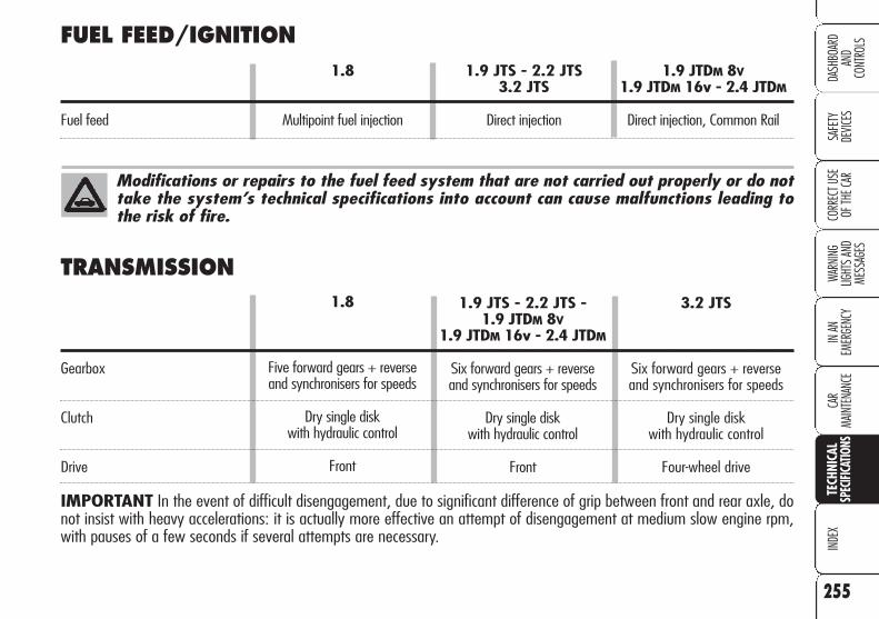
255
SAFE
TYDE
VICES
WARN
ING
LIGHT
S AN
D ME
SSAG
ES
IN AN
EM
ERGE
NCY
CAR
MAIN
TENA
NCE
INDE
XCO
RREC
T USE
OF
THE C
ARDA
SHBO
ARD
AND
CONT
ROLS
TECH
NICA
LSP
ECIFI
CATIO
NS
FUEL FEED/IGNITION1.8 1.9 JTS - 2.2 JTS 1.9 JTDM 8V
3.2 JTS 1.9 JTDM 16v - 2.4 JTDM
Fuel feed Multipoint fuel injection Direct injection Direct injection, Common Rail
Modifications or repairs to the fuel feed system that are not carried out properly or do nottake the system’s technical specifications into account can cause malfunctions leading tothe risk of fire.
1.9 JTS - 2.2 JTS - 1.9 JTDM 8V
1.9 JTDM 16v - 2.4 JTDM
Six forward gears + reverse and synchronisers for speeds
Dry single disk with hydraulic control
Front
1.8
Five forward gears + reverse and synchronisers for speeds
Dry single disk with hydraulic control
Front
TRANSMISSION
Gearbox
Clutch
Drive
IMPORTANT In the event of difficult disengagement, due to significant difference of grip between front and rear axle, donot insist with heavy accelerations: it is actually more effective an attempt of disengagement at medium slow engine rpm,with pauses of a few seconds if several attempts are necessary.
3.2 JTS
Six forward gears + reverse and synchronisers for speeds
Dry single disk with hydraulic control
Four-wheel drive

256
SAFE
TYDE
VICES
WARN
ING
LIGHT
S AN
D ME
SSAG
ESIN
AN
EMER
GENC
YCA
RMA
INTE
NANC
EIN
DEX
CORR
ECT U
SE
OF TH
E CAR
DASH
BOAR
DAN
DCO
NTRO
LSTE
CHNI
CAL
SPEC
IFICA
TIONS
1.8 - 1.9 JTS - 2.2 JTS - 3.2 JTS - 2.4 JTDM1.9 JTDM 8v - 1.9 JTDM 16v
Service brakes:
– front Disc, self-ventilating Disc, self-ventilating– rear Disc Disc, self-ventilating
Parking brake Controlled by hand lever, it works on rear brakes
IMPORTANT Water, ice and antifreeze salt on roads may deposit on the brake discs thus reducing braking efficiency at first braking.
1.8 - 1.9 JTS - 2.2 JTS - 3.2 JTS - 1.9 JTDM 8V - 1.9 JTDM 16v - 2.4 JTDM
Type Rack and pinion with hydraulic power steering
Turning radius (between pavements) 11.1
BRAKES
STEERING
1.8 - 1.9 JTS - 2.2 JTS - 3.2 JTS - 1.9 JTDM 8V - 1.9 JTDM 16v - 2.4 JTDM
Front High quadrilateral system
Rear Multi-link system
SUSPENSIONS

257
SAFE
TYDE
VICES
WARN
ING
LIGHT
S AN
D ME
SSAG
ES
IN AN
EM
ERGE
NCY
CAR
MAIN
TENA
NCE
INDE
XCO
RREC
T USE
OF
THE C
ARDA
SHBO
ARD
AND
CONT
ROLS
TECH
NICA
LSP
ECIFI
CATIO
NS
UNDERSTANDING TYRE MARKING fig. 5
Example: 205/55 R 16 91 V
205= Nominal width (S, distance be-tween sidewalls in mm).
55 = Percentage height/width ratio(H/S).
R = Radial tyre.
16 = Rim diameter in inches. (Ø).
91 = Load rating (capacity).
V = Maximum speed index.
WHEELS
RIMS AND TYRES
Pressed steel or alloy rims. Tubeless tyreswith radial carcass. The homologatedtyres are listed in the Log book.
IMPORTANT In the event of discrep-ancies between the information provid-ed on this “Owner’s Manual” and the“Log book”, consider the specificationsshown in the log book only.
A0E0186mfig. 5
On cars fitted with four-wheel drive, allfour tyres should be the same (brandand track) to prevent damaging the 4-WD system. The efficiency of the 4-WDsystem however, is not jeopardized iftyres with different wear conditions arefitted.
Attaining to the prescribed size, to en-sure safety of the car in movement, itmust be fitted with tyres of the samemake and type on all wheels.
IMPORTANT Do not use inner tubeswith Tubeless tyres.
SPACE-SAVER SPARE WHEELPressed steel rim. Tubeless tyre.

258
SAFE
TYDE
VICES
WARN
ING
LIGHT
S AN
D ME
SSAG
ESIN
AN
EMER
GENC
YCA
RMA
INTE
NANC
EIN
DEX
CORR
ECT U
SE
OF TH
E CAR
DASH
BOAR
DAN
DCO
NTRO
LSTE
CHNI
CAL
SPEC
IFICA
TIONS
UNDERSTANDING RIM MARKING
Example: 7 J x 16 H2 ET 43
7 = rim width in inches 1.
J = rim drop center outline (sideprojection where the tyre beadrests) 2.
16 = rim nominal diameter in inch-es (corresponds to diameter ofthe tyre to be mounted) (3 =Ø).
H2 = “hump” shape and number (re-lief on the circumference hold-ing the Tubeless tyre bead onthe rim).
43 = wheel camber angle (distancebetween the disc/rim support-ing plane and the wheel rimcentre line).
Maximum speed rating
Q = up to 160 km/h.R = up to 170 km/h.S = up to 180 km/h.T = up to 190 km/h.U = up to 200 km/h.H = up to 210 km/h.V = up to 240 km/h.W = up to 270 km/h.Y = up to 300 km/h.
Maximum speed ratingfor snow tyres
Q M + S = up to 160 km/h.T M + S = up to 190 km/h.H M + S = up to 210 km/h.
Load rating (capacity)
60 = 250 kg 84 = 500 kg61 = 257 kg 85 = 515 kg62 = 265 kg 86 = 530 kg63 = 272 kg 87 = 545 kg64 = 280 kg 88 = 560 kg65 = 290 kg 89 = 580 kg66 = 300 kg 90 = 600 kg67 = 307 kg 91 = 615 kg68 = 315 kg 92 = 630 kg69 = 325 kg 93 = 650 kg70 = 335 kg 94 = 670 kg71 = 345 kg 95 = 690 kg72 = 355 kg 96 = 710 kg73 = 365 kg 97 = 730 kg74 = 375 kg 98 = 750 kg75 = 387 kg 99 = 775 kg76 = 400 kg 100 = 800 kg77 = 412 kg 101 = 825 kg78 = 425 kg 102 = 850 kg79 = 437 kg 103 = 875 kg80 = 450 kg 104 = 900 kg81 = 462 kg 105 = 925 kg82 = 475 kg 106 = 950 kg83 = 487 kg

259
SAFE
TYDE
VICES
WARN
ING
LIGHT
S AN
D ME
SSAG
ES
IN AN
EM
ERGE
NCY
CAR
MAIN
TENA
NCE
INDE
XCO
RREC
T USE
OF
THE C
ARDA
SHBO
ARD
AND
CONT
ROLS
TECH
NICA
LSP
ECIFI
CATIO
NS
Traditional snow chains may not be used on tyres type 225/50 R17” only spider type chainscan be used. Tyres 235/45 R18” cannot be fitted with snow chains due to interference with thefender.
Also for 3.2 JTS version, snow chains shall be fitted on the FRONT axle of the car.
4,00B x17"
T125/80 R17
1.81.9 JTS
7Jx16” steel
205/55 R16 91V
7Jx16” steel
215/55 R16 93V
7Jx16” alloy
215/55 R16 93V
7,5Jx17” (*) alloy
225/50 R17 98W
8Jx18” alloy
235/45 R18 98W
2.2 JTS
7Jx16” steel
215/55 R16 93V
7Jx16” alloy
215/55 R16 93V
7,5Jx17” (*) alloy
225/50 R17 98W
8Jx18” alloy
235/45 R18 98W
3.2 JTS
7,5Jx17” (*) alloy
225/50 R17 98W
8Jx18” alloy
235/45 R18 98W
1.9 JTDM8v
7Jx16” steel
215/55 R16 93V
7Jx16” alloy
215/55 R16 93V
7,5Jx17” (*) alloy
225/50 R17 98W
8Jx18” alloy
235/45 R18 98W
1.9 JTDM16v
7Jx16” steel
215/55 R16 93V
7Jx16” alloy
215/55 R16 93V
7,5Jx17” (*) alloy
225/50 R17 98W
8Jx18” alloy
235/45 R18 98W
2.4 JTDM
7,5Jx17” (*) alloy
225/50 R17 98W
8Jx18” alloy
235/45 R18 98W
(*) Tyres that cannot be fitted with traditional snow chains. Only “spider” type chains can be used.
IMPORTANT Snow tyres with speed index H or superior are recommended.(▼) Unchainable tyres. Size certified and admitted only for PIRELLI 235/40 R19 96Y. When using winter tyres, use 225/50R17 98 tyres or 235/45 R18 98. Vehicles with TI fittings should not use 16” wheel rims.
TIVersions
8Jx19" alloy
235/40 R19 96Y (▼)
tyre
rim
tyre
rim
tyre
rim
tyre
rim
tyre
rim
tyre
rim
TYRES
Standardtyres
For versions/markets where applicable
Optionals
Space-saverspare wheel(for versions/markets where applicable)

260
SAFE
TYDE
VICES
WARN
ING
LIGHT
S AN
D ME
SSAG
ESIN
AN
EMER
GENC
YCA
RMA
INTE
NANC
EIN
DEX
CORR
ECT U
SE
OF TH
E CAR
DASH
BOAR
DAN
DCO
NTRO
LSTE
CHNI
CAL
SPEC
IFICA
TIONS
COLD TYRE INFLATION PRESSURE
(▼) Unchainable tyres. Size certified and admitted only for PIRELLI 235/40 R19 96Y. When using winter tyres, use 225/50 R17 98 tyres or235/45 R18 98. Vehicles with TI fittings should not use 16” wheel rims.Add +0.3 bar to the prescribed inflation pressure when the tyres are warm. Recheck pressure value with cold tyres.With snow tyres, add +0.2 bar to the inflation pressure value prescribed for standard tyres.
Inflate tyres to full load pressures if driving at continuous speed exceeding 160 km/h.
Space-saverspare wheel
T125/80 R17
4.2
WHEEL ANGLES
Tyres205/55 R16 91V
front rear
2.3 2.3
2.6 2.6
Tyres215/55 R16 93V
front rear
2.3 2.3
2.6 2.6
Tyres225/50 R17 98W
front rear
2.5 2.5
2.7 2.7
Tyres235/45 R18 98W
front rear
2.7 2.5
2.8 2.6
Tyres235/40 R19 96Y (▼)
front rear
2.7 2.5
2.8 2.6
average load bar
full load bar
All types
–35’ ± 18’max. difference right/left: 24’4° 15’ ± 18’
max. differenceright/left: 18’
–8’ ± 4’max. difference right/left: 4’
–40’ ± 18’max. difference right/left: 24’
13’ ± 7’(total toe-in: 26’ ± 7’)
4x2 Versions
–1° 1’± 18’max. difference right/left: 24’4° 15’± 18’
max. difference right/left: 18’
–7’± 4’max. difference right/left: 4’–1° 3’± 18’
max. difference right/left: 24’
11’± 7’(total toe-in: 22’± 7’)
4x4 Versions
–38’±18’max. difference right/left: 24’4° 15’ ± 18’
max. difference right/left: 18’
–7’ ± 4’max. difference right/left: 4’
–1° 3’ ± 18’max. difference right/left: 24’
11’ ± 7’(total toe-in: 22’ ± 7’)
TI Versions
Frontwheels
Rearwheels
– camber
– caster
– half toe-in (per wheel)
– camber
– half toe-in (per wheel)
VEHICLE GEOMETRY The TI fittings present lower suspensions of 20 mm with respects to the other versions.

261
SAFE
TYDE
VICES
WARN
ING
LIGHT
S AN
D ME
SSAG
ES
IN AN
EM
ERGE
NCY
CAR
MAIN
TENA
NCE
INDE
XCO
RREC
T USE
OF
THE C
ARDA
SHBO
ARD
AND
CONT
ROLS
TECH
NICA
LSP
ECIFI
CATIO
NSVersions A B C D E F G H
1.8 - 1.9 JTS - 2.2 JTS - 3.2 JTS - 1.9 JTDM 8v - 4660 1000 2700 960 1422 1578 1828 1555
1.9 JTDM 16v - 2.4 JTDM1417 (■) 1593 (■) 1573 (■)
DIMENSIONSDimensions are expressed in mm and refer to the car fitted with standard tyres.
Min. size variations when optional tyres arefitted.
The height refers to the car unladen.
BOOT VOLUME
Boot volume .............. 405 dm3
A0E0044mfig. 6
(■) With tyres 215/55 R16”

262
SAFE
TYDE
VICES
WARN
ING
LIGHT
S AN
D ME
SSAG
ESIN
AN
EMER
GENC
YCA
RMA
INTE
NANC
EIN
DEX
CORR
ECT U
SE
OF TH
E CAR
DASH
BOAR
DAN
DCO
NTRO
LSTE
CHNI
CAL
SPEC
IFICA
TIONS
Dimensions are expressed in mm and refer to the car fitted with standard tyres.
Min. size variations when optional tyres arefitted.
The height refers to the car unladen.
BOOT VOLUME
Boot volume .............. 445 dm3
A0E0307mfig. 7
Versions A B C D E (*) F G H
1.8 - 1.9 JTS - 2.2 JTS - 3.2 JTS - 1.9 JTDM 8v - 4660 1000 2700 960 1422 1578 1828 1555
1.9 JTDM 16v - 2.4 JTDM1417 (■) 1593 (■) 1573 (■)
(■) With tyres 215/55 R16”
(*) With roof racks/ski racks (where provided): 1452/1447 (with 215/55 R16" tyres)

263
SAFE
TYDE
VICES
WARN
ING
LIGHT
S AN
D ME
SSAG
ES
IN AN
EM
ERGE
NCY
CAR
MAIN
TENA
NCE
INDE
XCO
RREC
T USE
OF
THE C
ARDA
SHBO
ARD
AND
CONT
ROLS
TECH
NICA
LSP
ECIFI
CATIO
NS
PERFORMANCESALOON VERSIONS Top speed Acceleration Kilometer with standing start
from 0-100 km/hkm/h sec. sec.
1.8 206 10.2 31.3
1.9 JTS 212 9.7 30.7
2.2 JTS 222 8.8 29.6
3.2 JTS 240 7.0 27.5
1.9 JTDM 8v 191 11.0 32.8
1.9 JTDM 16v 210 9.4 30.8
2.4 JTDM 228 8.4 29.2
SPORTWAGON VERSIONS Top speed Acceleration Kilometer with standing startfrom 0-100 km/h
km/h sec. sec.
1.8 204 10.4 31.5
1.9 JTS 210 9.9 31.3
2.2 JTS 220 9.0 30.3
3.2 JTS 237 7.2 27.9
1.9 JTDM 8v 190 11.2 33.3
1.9 JTDM 16v 208 9.6 31.3
2.4 JTDM 226 8.6 29.7

2.2 JTS
1490
120011002010
520
1500
75
50
3.2 JTS
1680
130011002200
520
1700
75
50
1.9 JTDM 8v
1525
120011002045
520
1500
75
50
1.9 JTDM 16v
1535
120011002055
520
1500
75
50
2.4 JTDM
1630
130011002150
520
1500
75
50
1.9 JTS
1480
120011002000
520
1500
75
50
264
SAFE
TYDE
VICES
WARN
ING
LIGHT
S AN
D ME
SSAG
ESIN
AN
EMER
GENC
YCA
RMA
INTE
NANC
EIN
DEX
CORR
ECT U
SE
OF TH
E CAR
DASH
BOAR
DAN
DCO
NTRO
LSTE
CHNI
CAL
SPEC
IFICA
TIONS
WEIGHTS1.8
1430
120011001950
520
1400
75
50
Weights (kg)Saloon versions
Weight empty (including fluids, 90% fuel in the tank and no optional)
Maximumadmitted load (*)
– front axle– rear axle– total
Payload includingdriver (**)
Towable loads
Max. load on ball
Maximum load on roof
(*) Loads not to be exceeded. The driver is responsible for arranging the loads in the boot an/or on the roof so that they comply with these limits.
(**) If special equipment is fitted (sunroof, tow hitch etc.) the unladen weight increases, thus reducing the payload as specified inthe maximum weight allowed.

1.9 JTS
1530
120011002050
520
1500
75
80
2.2 JTS
1540
120011002060
520
1500
75
80
3.2 JTS
1730
130011002250
520
1800
75
80
1.9 JTDM 8v
1575
120011002095
520
1500
75
80
1.9 JTDM 16v
1585
120011002105
520
1500
75
80
2.4 JTDM
1680
130011002200
520
1500
75
80
265
SAFE
TYDE
VICES
WARN
ING
LIGHT
S AN
D ME
SSAG
ES
IN AN
EM
ERGE
NCY
CAR
MAIN
TENA
NCE
INDE
XCO
RREC
T USE
OF
THE C
ARDA
SHBO
ARD
AND
CONT
ROLS
TECH
NICA
LSP
ECIFI
CATIO
NS
1.8
1480
120011002000
520
1400
75
80
Weights (kg)Sportwagon versions
Weight empty (including fluids, 90% fuel in the tank and no optional)
Maximumadmitted load (*)
– front axle– rear axle– total
Payload includingdriver (**)
Towable loads
Max. load on ball
Maximum load on roof (***)
(*) Loads not to be exceeded. The driver is responsible for arranging the loads in the boot an/or on the roof so that they comply with these limits.
(**) If special equipment is fitted (sunroof, tow hitch etc.) the unladen weight increases, thus reducing the payload as specified inthe maximum weight allowed.
(***) Lineaccessori Alfa Romeo roof rack, max capacity: 50 kg.

1.9 JTDM8v
70 ❍
10 ❍
7.5
4.6 ❑
2.3
6.0
1.9 JTDM16v
70 ❍
10 ❍
7.5
4.6 ❑
2.3
6.0
2.4 JTDM
70 ❍
10 ❍
7.35
6.4 ❑
2.8
6.0
1.9 JTS
70 ●
10 ●
8.15
5.4 ■
2.3
6.0
2.2 JTS
70 ●
10 ●
8.15
5.4 ■
2.3
6.0
3.2 JTS
69 ●
10 ●
10.3
5.4 ■
2.8 (Õ)
6.0
266
SAFE
TYDE
VICES
WARN
ING
LIGHT
S AN
D ME
SSAG
ESIN
AN
EMER
GENC
YCA
RMA
INTE
NANC
EIN
DEX
CORR
ECT U
SE
OF TH
E CAR
DASH
BOAR
DAN
DCO
NTRO
LSTE
CHNI
CAL
SPEC
IFICA
TIONS
CAPACITIESSpecified fuels andoriginal lubricants
● Unleaded petrolwith no less than 95 R.O.N. (EN228 Specification)❍ Diesel fuel for motor vehi-cles (EN590 Specification)
Mixture of 50% water andPARAFLUUP
■ SELENIA StAR❑ SELENIA WR
TUTELA CAR MATRYX(Õ) TUTELA MULTIAXLE
Mixture of water and liquidTUTELAPROFESSIONAL SC 35
1.8
70 ●
10 ●
8.0
4.5 ■
1.6
6.0
Fuel tank: litres– including
a reserve of litres
Engine cooling systemlitres
Lubrication system litresengine
Mechanical gearbox/differential litres
Windscreen/headlight washer fluid reservoir: litres
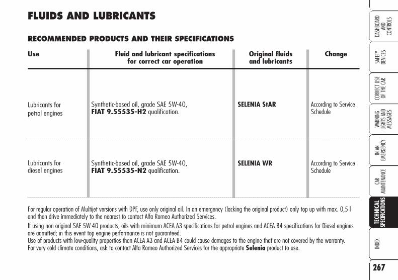
267
SAFE
TYDE
VICES
WARN
ING
LIGHT
S AN
D ME
SSAG
ES
IN AN
EM
ERGE
NCY
CAR
MAIN
TENA
NCE
INDE
XCO
RREC
T USE
OF
THE C
ARDA
SHBO
ARD
AND
CONT
ROLS
TECH
NICA
LSP
ECIFI
CATIO
NS
FLUIDS AND LUBRICANTS
RECOMMENDED PRODUCTS AND THEIR SPECIFICATIONS
Use Fluid and lubricant specifications Original fluids Changefor correct car operation and lubricants
Lubricants forpetrol engines
Lubricants for diesel engines
Synthetic-based oil, grade SAE 5W-40, FIAT 9.55535-H2 qualification.
Synthetic-based oil, grade SAE 5W-40,FIAT 9.55535-N2 qualification.
SELENIA StAR
SELENIA WR
According to ServiceSchedule
According to ServiceSchedule
For regular operation of Multijet versions with DPF, use only original oil. In an emergency (lacking the original product) only top up with max. 0,5 land then drive immediately to the nearest to contact Alfa Romeo Authorized Services.If using non original SAE 5W-40 products, oils with minimum ACEA A3 specifications for petrol engines and ACEA B4 specifications for Diesel enginesare admitted; in this event top engine performance is not guaranteed.Use of products with low-quality properties than ACEA A3 and ACEA B4 could cause damages to the engine that are not covered by the warranty.For very cold climate conditions, ask to contact Alfa Romeo Authorized Services for the appropriate Selenia product to use.

268
SAFE
TYDE
VICES
WARN
ING
LIGHT
S AN
D ME
SSAG
ESIN
AN
EMER
GENC
YCA
RMA
INTE
NANC
EIN
DEX
CORR
ECT U
SE
OF TH
E CAR
DASH
BOAR
DAN
DCO
NTRO
LSTE
CHNI
CAL
SPEC
IFICA
TIONS
Synthetic-based oil, grade SAE 75W-85 that passes API GL 4 specifications, FIAT 9.55550
Synthetic-based oil, grade SAE 75W-90 that passes API GL-5 specifications, ZF-TE ML 18
Lubricant for automatic transmissions that passes "ATF DEXRON III" specification
Lithium-soap-based grease with molybdenum bisulphate.
Lithium soap based grease. NLGI 0 consistency
Synthetic fluid FMVSS no. 116, DOT 4, ISO 4925, SAE J-1704CUNA NC 956-01
Protective with antifreeze action, red colour based on inhibitedmonoethylen glycol and organic formula,that passes CUNA NC 956-16, ASTM D 3306 specifications
Mixture of alcohol and surfactants CUNA NC 956-11
TUTELA CARMATRYX
TUTELAMULTIAXLE
TUTELA GI/E
TUTELA STAR 500
TUTELAMRM ZERO
TUTELA TOP 4
PARAFLUUP
TUTELAPROFESSIONALSC 35
Mechanical gearbox anddifferential
Rear differential andtransmission unit(3.2 JTS version)
Power steering
CV joints on wheel side
CV jointson differential side
Brake and clutchhydraulic controls
Cooling circuits.Proportion: 50% down to–35° C. Not to be mixedwith products havingdifferent formulas
To be used diluted or undiluted
Use Fluid and lubricant specifications Original fluids Applicationsfor correct car operation and lubricants
Lubricants andgreasesfor transmission
Windscreen/headlight washerfluid
Protective agent forradiators
Brake fluid

269
SAFE
TYDE
VICES
WARN
ING
LIGHT
S AN
D ME
SSAG
ES
IN AN
EM
ERGE
NCY
CAR
MAIN
TENA
NCE
INDE
XCO
RREC
T USE
OF
THE C
ARDA
SHBO
ARD
AND
CONT
ROLS
TECH
NICA
LSP
ECIFI
CATIO
NS
– extra-urban cycle: frequent ac-celerating in all gears, simulating ex-traurban use of the car; the speed variesbetween 0 and 120 km/h;
– combined consumption: is cal-culated weighing about 37% of urbancycle consumption and about 63% ofextraurban consumption.
IMPORTANT The type of route,traffic situations, weather condi-tions, driving style, general con-ditions of the car, trim level/equipment/accessories, load, cli-mate control system, roof rack,other situations that affect airdrag may lead to different fuelconsumption levels than thosemeasured.
FUEL CONSUMPTIONThe fuel consumption figures given inthe table below are determined on thebasis of the homologation tests setdown by specific European Directives.The procedures below are followed formeasuring consumption:
– urban cycle: cold starting followedby driving that simulates urban use ofthe car;
Fuel consumption according to Urban Extra-urban Combined1999/100/EC Directive (litres x 100 km)
1.8 10.4 (�) 6.1 (�) 7.7 (�)10.7 (�) 6.3 (�) 7.9 (�)
1.9 JTS 12,2 (�) 6.6 (�) 8.7 (�)12.4 (�) 6.7 (�) 8.8 (�)
2.2 JTS 13.0 (�) 7.3 (�) 9.4 (�)13.2 (�) 7.3 (�) 9.5 (�)
3.2 JTS 16.9 (�) 8.4 (�) 11.5 (�)17.0 (�) 8.4 (�) 11.6 (�)
1.9 JTDM 8v 7.8 (�) 4.9 (�) 5.9 (�)7.9 (�) 4.9 (�) 6.0 (�)
1.9 JTDM 16v 8.1 (�) 4.8 (�) 6.0 (�)8.3 (�) 4.8 (�) 6.1 (�)
2.4 JTDM 9.2 (�) 5.4 (�) 6.8 (�)9.4 (�) 5.6 (�) 7.0 (�)
(�) Saloon versions (�) Sportwagon versions

270
SAFE
TYDE
VICES
WARN
ING
LIGHT
S AN
D ME
SSAG
ESIN
AN
EMER
GENC
YCA
RMA
INTE
NANC
EIN
DEX
CORR
ECT U
SE
OF TH
E CAR
DASH
BOAR
DAN
DCO
NTRO
LSTE
CHNI
CAL
SPEC
IFICA
TIONS
CO2 EMISSIONS
The CO2 emission levels given in the following tables refer to combined consumption.
CO2 EMISSIONS ACCORDING TO 1999/100/EC DIRECTIVE (g/km)
Sportwagon versions
Saloon versions
1.8 1.9 JTS 2.2 JTS 3.2 JTS 1.9 JTDM 8v 1.9 JTDM 16v 2.4 JTDM
181 205 221 273 157 159 179
1.8 1.9 JTS 2.2 JTS 3.2 JTS 1.9 JTDM 8v 1.9 JTDM 16v 2.4 JTDM
187 209 224 275 159 162 184
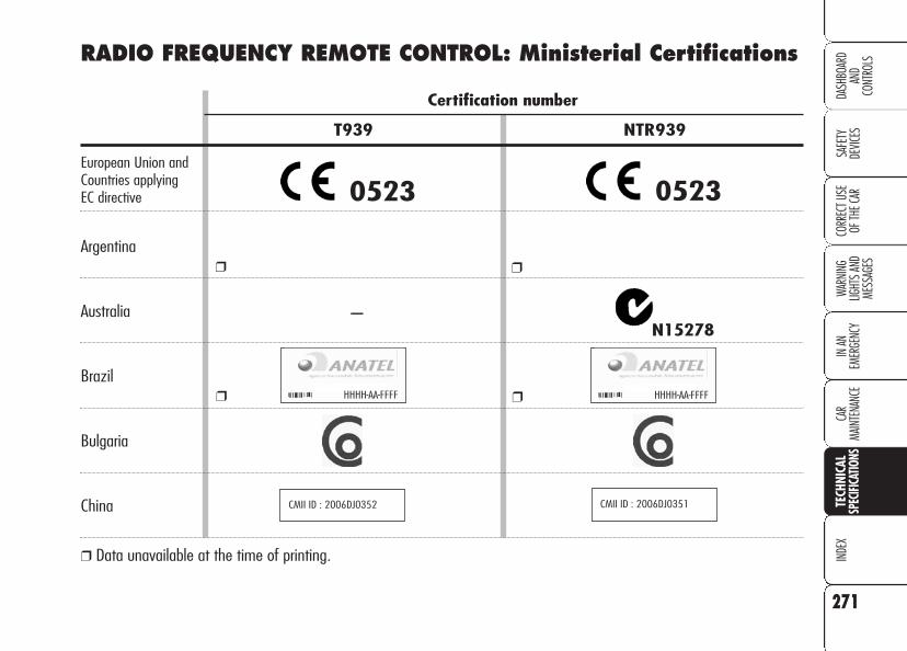
271
SAFE
TYDE
VICES
WARN
ING
LIGHT
S AN
D ME
SSAG
ES
IN AN
EM
ERGE
NCY
CAR
MAIN
TENA
NCE
INDE
XCO
RREC
T USE
OF
THE C
ARDA
SHBO
ARD
AND
CONT
ROLS
TECH
NICA
LSP
ECIFI
CATIO
NS
Certification number
T939 NTR939
European Union and Countries applying EC directive
Argentina
Australia
Brazil
Bulgaria
China
❒ Data unavailable at the time of printing.
N15278
HHHH-AA-FFFFHHHH-AA-FFFF
CMII ID : 2006DJ0352 CMII ID : 2006DJ0351
RADIO FREQUENCY REMOTE CONTROL: Ministerial Certifications
0523 0523
❒ ❒
–
❒ ❒

272
SAFE
TYDE
VICES
WARN
ING
LIGHT
S AN
D ME
SSAG
ESIN
AN
EMER
GENC
YCA
RMA
INTE
NANC
EIN
DEX
CORR
ECT U
SE
OF TH
E CAR
DASH
BOAR
DAN
DCO
NTRO
LSTE
CHNI
CAL
SPEC
IFICA
TIONS
Certification number
T939 NTR939
Malaysia
Mexico
Morocco
Singapore
South Africa
Taiwan
❒ Data unavailable at the time of printing.
AGREE PAR L’ANRT MAROCNuméro d’agrément : MR 2395 ANRT 2006
Date d’agrément : 13/01/2006
AGREE PAR L’ANRT MAROCNuméro d’agrément : MR 2394 ANRT 2006
Date d’agrément : 13/01/2006
Complies with IDA StandardsDA 104022
Complies with IDA StandardsDA 104022
TA-2005/701APPROVED
TA-2005/702APPROVED
YYYYXXXX-XXX YYYYXXXX-XXX
AA 000000 E AA 000000 E
❒ ❒
❒ ❒
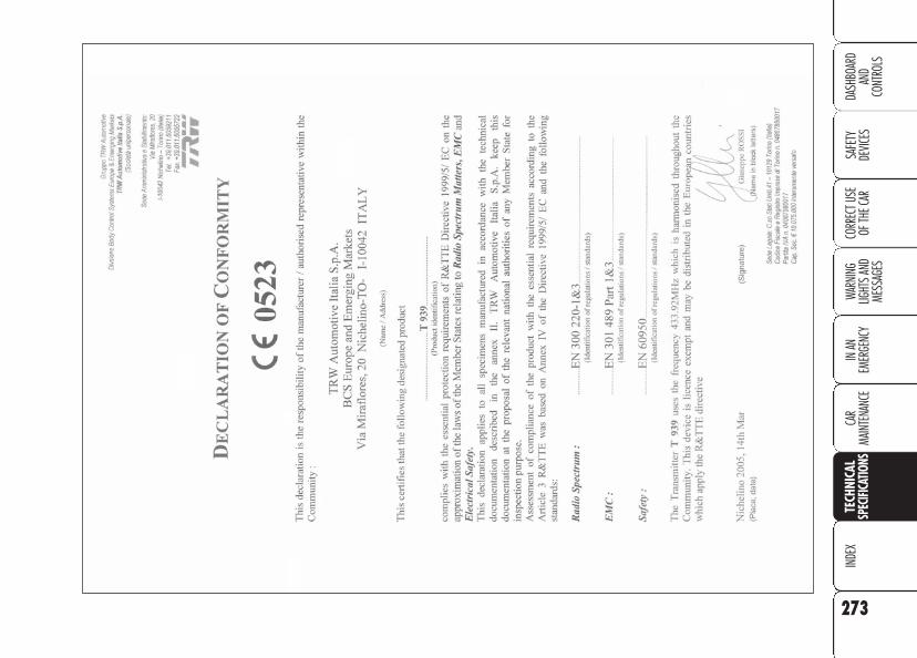
273
SAFE
TYDE
VICES
WARN
ING
LIGHT
S AN
D ME
SSAG
ES
IN AN
EM
ERGE
NCY
CAR
MAIN
TENA
NCE
INDE
XCO
RREC
T USE
OF
THE C
ARDA
SHBO
ARD
AND
CONT
ROLS
TECH
NICA
LSP
ECIFI
CATIO
NS

274
SAFE
TYDE
VICES
WARN
ING
LIGHT
S AN
D ME
SSAG
ESIN
AN
EMER
GENC
YCA
RMA
INTE
NANC
EIN
DEX
CORR
ECT U
SE
OF TH
E CAR
DASH
BOAR
DAN
DCO
NTRO
LSTE
CHNI
CAL
SPEC
IFICA
TIONS

AALLFFAA 115599 SSPPOORRTTWWAAGGOONNREARSCREEN WIPER .......................................... 276
BOOT ............................................................... 277
ROOF RACK/SKI RACK ....................................... 284
PRESETTING FOR MOUNTING THE "UNIVERSAL ISOFIX" CHILD RESTRAINT SYSTEM ... 285
IF AN EXTERIOR LIGHT BURNS OUT ..................... 286
IF AN INTERIOR LIGHT BURNS OUT ...................... 289
IF A FUSE BLOWS.............................................. 291
275
ALFA
159 S
PORT
WAGO
N

Never use the wiper toremove ice or snow fromthe rear window. In these
conditions, the wiper is submittedto excessive effort that results inmotor protection cutting in andwiper operation inhibition for fewseconds as a consequence. Shouldit be not possible to restore itsoperation, contact Alfa RomeoAuthorized Service.
HANGING THE REARSCREENWIPER BLADE
Proceed as follows:
❒ raise the cover A-fig. 2, slackenthe nut B and remove the arm C;
❒ position the new arm correctly, ful-ly tighten the nut B and then lowerthe cover A.
REARSCREEN WIPER
OPERATION
Rear window wiperactivation/deactivation
Turning the unstable ring nut A-fig. 1to position 'ON/OFF will obtain flickwipe of the rear window wiper. To turnit off, turn the ring nut back to position' ON/OFF.
Rear window "smart"washing
Turning the unstable ring nut A-fig. 1to position & will obtain rear windowwashing. Keeping the unstable ring nutat position & it will be possible to acti-vate with just one movement both thewindscreen wiper and the rear windowwiper; the latter comes actually into ac-tion automatically when the unstablering nut is kept at position & for overhalf a second.
276
ALFA
159
SPO
RTW
AGON
A0E0264mfig. 1 A0E0267mfig. 2
The rear window wiper stops workinga few strokes after releasing the ringnut; a further stroke after about 6 sec-onds completes the wiping operation.

SPRAY NOZZLE
If the jet of fluid is inadequate, firstlycheck that there is fluid in the reservoir(see "Checking fluid levels" in section"Car maintenance").
Then check that the nozzle holes A-fig. 3 are not clogged, if necessary usea needle to clean them.
277
ALFA
159
SPO
RTW
AGON
A0E0269mfig. 4
A0E0263mfig. 5
A0E0268mfig. 3
BOOT
TAILGATE EMERGENCYOPENING FROM THE INSIDE
To open the tailgate from the inside ifthe battery is flat or the electric tailgatelock is failing, proceed as follows:
❒ tilt the rear seats completely (seeparagraph "Extending the boot" insection "Dashboard and controls");
❒ remove the rear head restraints;
❒ take the screwdriver from the toolcontainer and working inside theboot (on the rear part), fit it into seatA-fig. 4 and then operate lever B-fig. 5.

ODDMENT COMPARTMENTSfig. 8 - 9
The boot sides are equipped with two odd-ment compartments closed by a cover.
To open the cover press button A andturn it downwards.
278
ALFA
159
SPO
RTW
AGON
If you want to carryreserve fuel in a can,
follow law regulations, onlyusing a certified can, suitablyfastened to the load securingeyelets. Even in this way therisk of fire is increased in thecase of an accident.
WARNING
A heavy load that hasnot been secured may
cause serious harm.
WARNING
A0E0273mfig. 8
A0E0272mfig. 9
A0E0270mfig. 6 A0E0271mfig. 7
ANCHORING THE LOAD
The boot houses 4 hooks (see fig. 6and fig. 7) for anchoring ropes in or-der to guarantee perfect load anchoring.
Hooks shall also be used to secure theluggage retaining net (available as op-tional, for versions/markets where ap-plicable, at Alfa Romeo Authorised Ser-vices).

CURRENT OUTLET (optional for versions/markets where applicable)
The current outlet is located on the leftside of the boot.
To use the current outlet, open the lidA-fig. 10. The current outlet onlyworks with the key fitted into the igni-tion device and can only be used to pow-er accessories having max. 15A intake(180 W).
279
ALFA
159
SPO
RTW
AGON
A0E0274mfig. 10
Never use the outlet foraccessories with powerover the max. specified
one. Long power intake can rundown the battery and inhibitengine starting.
A0E0281mfig. 11 A0E0282mfig. 12
LUGGAGE NET (optional for versions/markets where applicable)
The left and right sides of the boot arequipped with a luggage retainer net.
– fig. 11 - version with side lid(where provided)
– fig. 12 - version without side lid
As optional, for versions/markets whereapplicable, an additional luggage re-tainer net can be fitted.

Use the seats A-fig. 13 located in thefront part of the boot to hook the net asshown in fig. 16.
Using seats B-fig. 14 to secure the netto the rear side of the boot.
280
ALFA
159
SPO
RTW
AGON
A0E0275mfig. 13 A0E0276mfig. 15
A0E0277mfig. 16
To secure the net, fit hooks A-fig. 15into seats B and press downwards.
To release the net, take it out upwardswhile keeping button C pressed.
A0E0308mfig. 14

281
ALFA
159
SPO
RTW
AGON
IMPORTANT To remove the net rollit up and check whether also the pas-senger's compartment separation net(where provided) is rolled up (seenext paragraph), then pull up lever D-fig. 19. Raise the net and take it outfrom the boot.
LUGGAGE COMPARTMENTCOVER
The luggage compartment cover A-fig.17 can be rolled up and removed.
To roll it up remove the two rear pins B-fig. 18 from their housings.
IMPORTANT Hold the cover by han-dle C-fig. 17 and guide it during rollingup.
A0E0278mfig. 17 A0E0279mfig. 18 A0E0280mfig. 19
To refit the net, proceed as follows:
❒ fit the net into the proper seat on theleft side (side without lever);
❒ keep the lever D-fig. 19 up and fitthe net into the proper seat on theright side;
❒ release lever D.

PASSENGER'SCOMPARTMENT UPPERSEPARATION NET (where provided)
In addition to the luggage compartmentcover, certain versions are also fittedwith a passenger's compartment upperseparation net fig. 20.
The net for separating the passenger'scompartment from the boot is containedinto a special bar.
A0E0283mfig. 20 A0E0287mfig. 21
A0E0288mfig. 22
To extend it, take it out of the reel bytaking tongue A-fig. 21 and secureends B-fig. 22 into the two housingsC-fig. 23 (one per side) located onthe roof of the car.
282
ALFA
159
SPO
RTW
AGON
Do not put objects onthe cover which maydamage it.
The objects put on thecover may be thrown
forwards and injure passen-gers should you brake sharplyor in the event of an accident.Your are recommended to usethe passenger's compartmentseparation net.
WARNING

SOUND SYSTEM
CD Changer (where provided)
O certain versions, behind the right bootlid, is fitted a CD Changer for 10 discs(see fig. 25).
Amplifier (where provided)
Versions equipped with Bose Hi-Fi sys-tem also have an amplifier behind theleft boot lid.
283
ALFA
159
SPO
RTW
AGON
To roll up the net, release ends B-fig. 22 from housings C-fig. 23 andguide it during rolling.
A0E0291mfig. 24A0E0284mfig. 23 A0E0305mfig. 25
Passenger's compartmentseparating netremoval/refitting
To remove the net proceed as follows:
Press button D-fig. 24 as shown inthe figure, move the separating net re-leasing it from its seat, on both left andright side. make the net slide as shownin the figure, removing the pins fromtheir seats.
To refit the net reverse the removal op-erations described previously.

284
ALFA
159
SPO
RTW
AGON
A0E0286mfig. 27
ROOF RACK/SKI RACK(optional for versions/markets where applicable)
The car can be fitted with two longitu-dinal bars fig. 27 that can be used, byadding special accessories to carry var-ious objects (e.g.: skis, windsurf, etc.)
IMPORTANT Never exceed the max.permissible loads (see section "Techni-cal Specifications").
FUEL CAP EMERGENCYOPENING
In the event of a failure, to open thefuel cap proceed as follows:
❒ open the fuse box lid A-fig. 26 onthe right side of the boot as shownby the arrow;
❒ pull the string B set aside the usebox.
A0E0285mfig. 26

285
ALFA
159
SPO
RTW
AGON
It is possible to mount both the tradi-tional restraint system and the "Univer-sal Isofix" one. Remember that in caseof Universal Isofix child's seats, you canonly use all those seats approved withthe ECE R44/03 writing "UniversalIsofix".
PRESETTING FORMOUNTING THE"UNIVERSALISOFIX" CHILDRESTRAINT SYSTEM
This car is preset for mounting the Uni-versal Isofix child restraint system, anew European standardised system forcarrying children safely. fig. 28 showsan example of child restraint system.The Universal Isofix child's seat coversweight group 1.
Due to its different anchoring system,the Universal Isofix child's seat shall beanchored to the proper lower metal fas-teners A-fig. 29, set between rearseat back and cushion. The upper belt(available with the child's seat) shall bethen secured to fastener B-fig. 30 setin the boot at child's seat level.
To use fastener B, proceed as follows:
❒ tilt the rear set backrest (see para-graph "Boot" in section "Dashboardand controls");
❒ pull up fastener B and then securethe belt to the fastener.
A0E0174mfig. 29
A0E0289mfig. 30fig. 28 A0E0241m

❒ remove the bulb holder unit by press-ing the retaining tabs B-fig. 32;
286
ALFA
159
SPO
RTW
AGON
IF AN EXTERIORLIGHT BURNS OUT
For the type of bulb and power rating,see paragraph “When needing tochange a bulb" in section "In an emer-gency".
IMPORTANT Before changing a bulb,read carefully the instructions given insection "In an emergency".
REAR LIGHT UNITS
Reversing light/rear fog lights
To replace the bulbs proceed as follows:
❒ open the tailgate;
❒ remove cover A-fig. 31 workingwith a screwdriver in the point indi-cated by the arrow;
IMPORTANT To release the inspec-tion lid, protect the screwdriver tip witha cloth to prevent scratching.
Mount the child re-straint system only
with the car stationary. TheUniversal Isofix child restraintsystem is properly anchored tothe mounting brackets whenclicks are heard. In any case,keep to the installation in-structions that must be pro-vided by the child restraintsystem's Manufacturer.
WARNING
At Lineaccessori Alfa Romeo you canfind the "Universal Isofix" "Duo Plus"child's seat.
For any further detail on installationand/or use, refer to the “InstructionsManual” that must be provided by thechild restraint system's Manufacturer.
A0E0292mfig. 31
A0E0293mfig. 32

287
ALFA
159
SPO
RTW
AGON
Taillight bulb on tailgate
To replace the bulbs proceed as follows:
❒ open the tailgate;
❒ remove the cover A-fig. 31 work-ing in the point shown by the arrow;
❒ remove the bulb holder unit by press-ing the retaining tabs B-fig. 32;
❒ remove and replace the burnt-outbulb by pressing it slightly and turn-ing it counterclockwise fig. 33:
C: reversing light bulb on passengerside or right side;
C: rear fog light bulb on driver side orleft side;
❒ refit the bulb holder unit securing itproperly using the retaining tabs B-fig. 32;
❒ close cover A-fig. 31.
A0E0294mfig. 33
❒ remove and replace the burnt-outbulb by pressing it slightly and turn-ing it counterclockwise fig. 33:
D: taillight bulb on right/left headlight
❒ refit the bulb holder unit securing itproperly using the retaining tabs B-fig. 32;
❒ close cover A-fig. 31.
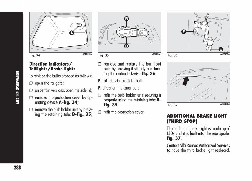
288
ALFA
159
SPO
RTW
AGON
Direction indicators/Taillights/Brake lights
To replace the bulbs proceed as follows:
❒ open the tailgate;
❒ on certain versions, open the side lid;
❒ remove the protection cover by op-erating device A-fig. 34;
❒ remove the bulb holder unit by press-ing the retaining tabs B-fig. 35;
A0E0296mfig. 35 A0E0297mfig. 36
A0E0298mfig. 37
❒ remove and replace the burnt-outbulb by pressing it slightly and turn-ing it counterclockwise fig. 36:
E: taillight/brake light bulb;
F: direction indicator bulb
❒ refit the bulb holder unit securing itproperly using the retaining tabs B-fig. 35;
❒ refit the protection cover.
A0E0295mfig. 34
ADDITIONAL BRAKE LIGHT(THIRD STOP)
The additional brake light is made up ofLEDs and it is built into the rear spoilerfig. 37.
Contact Alfa Romeo Authorized Servicesto have the third brake light replaced.
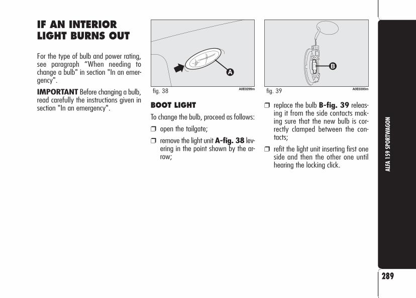
289
ALFA
159
SPO
RTW
AGON
BOOT LIGHT
To change the bulb, proceed as follows:
❒ open the tailgate;
❒ remove the light unit A-fig. 38 lev-ering in the point shown by the ar-row;
❒ replace the bulb B-fig. 39 releas-ing it from the side contacts mak-ing sure that the new bulb is cor-rectly clamped between the con-tacts;
❒ refit the light unit inserting first oneside and then the other one untilhearing the locking click.
IF AN INTERIORLIGHT BURNS OUT
For the type of bulb and power rating,see paragraph “When needing tochange a bulb" in section "In an emer-gency".
IMPORTANT Before changing a bulb,read carefully the instructions given insection "In an emergency".
A0E0299mfig. 38 A0E0300mfig. 39
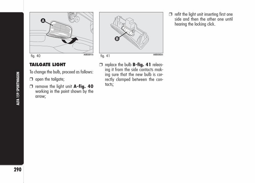
❒ replace the bulb B-fig. 41 releas-ing it from the side contacts mak-ing sure that the new bulb is cor-rectly clamped between the con-tacts;
❒ refit the light unit inserting first oneside and then the other one untilhearing the locking click.
TAILGATE LIGHT
To change the bulb, proceed as follows:
❒ open the tailgate;
❒ remove the light unit A-fig. 40working in the point shown by thearrow;
290
ALFA
159
SPO
RTW
AGON
A0E0301mfig. 40 A0E0302mfig. 41

IF A FUSE BLOWS
The fuse specific for the Sportwagon ver-sion is located in the fuse box at theright side of the boot (see “In an emer-gency” chapter).
IMPORTANT Before changing a bulb,read carefully the instructions given insection "In an emergency".
291
ALFA
159
SPO
RTW
AGON
A0E0303mfig. 42 A0E0304mfig. 43
To open the fuse box, proceed as fol-lows:
❒ use handle B to open the right lid(where provided) A-fig. 42;
COMPONENT FUSE AMPERE
Cigar lighter outlet F55 15
❒ open the fuse box lid C-fig. 43working in the point shown by thearrow.

292
SAFE
TYDE
VICES
WARN
ING
LIGHT
S AN
D ME
SSAG
ESIN
AN
EMER
GENC
YCA
RMA
INTE
NANC
ETE
CHNI
CAL
SPEC
IFICA
TIONS
CORR
ECT U
SE
OF TH
E CAR
DASH
BOAR
DAN
DCO
NTRO
LSIN
DEX
Bodywork (cleaning) ................245Bonnet ...................................105Boot ................................101-277– light replacement ................208
Brakes ....................................256Bulb (replacement) ..................196– general instructions .............196– types of bulbs .....................197
Capacities ...............................266Car inactivity ............................164Car maintenance .................223– periodical checks .................227– use of the car under heavy
conditions ..........................227– service Schedule .................225– scheduled service ................224
Carrying children safely .............135– child restraint systems .........138– passenger’s seat compliance .138– presetting for mounting the
“Universal Isofix” child restraint system .......................140-285
Ceiling lights– front ................................. 78– rear .................................. 80
Checking fluid levels .................228Child lock device ...................... 97Cigar lighter ............................. 85Climate control system .............. 53– automatic two-/three-zone .. 58– manual .............................. 55
CO2 emissions .........................270CODE card ............................... 12Containing running costs ...........157Controls .................................. 81Correct use of the car ........151Courtesy mirror light– bulb replacement ................206
Cruise Control .......................... 76
Dashboard and controls .... 6Dashboard buttons ................... 72Diesel fuel filter ........................236Dimensions .............................261Dipped beam headlights– bulb replacement ................200– control ............................... 70
Direction indicators– bulb replacement 200-201-203– control ............................... 70
Doors ..................................... 96
ABS system ............................108Accessories purchased by the owner .........................117
Additional heater ...................... 69Air/pollen filter ........................236Air vents ................................. 54Alarm ..................................... 17Alfa Romeo CODE system .......... 10Alfa 159 Sportwagon .......275Armrest– central ............................... 82– rear ............................ 83-84
Ashtray ................................... 87ASR system .............................112At the filling station ..................125Automatic headlight sensor ........ 71Automatic two/three-zone climate control system ............ 58
Battery– checking the charge ............237– jump starting ......................182– recharging ..........................219– replacing ............................238– useful advice for
lengthening the life .............239
IINNDDEEXX

293
SAFE
TYDE
VICES
WARN
ING
LIGHT
S AN
D ME
SSAG
ES
IN AN
EM
ERGE
NCY
CAR
MAIN
TENA
NCE
TECH
NICA
LSP
ECIFI
CATIO
NSCO
RREC
T USE
OF
THE C
ARDA
SHBO
ARD
AND
CONT
ROLS
INDE
X
Fuel cut-off and power supply switches ................................ 81
Fuel feed ................................255Fuel filler cap ...........................126Fuses (replacement) ..........209-291
Gearbox (use) ........................156Glass/can holder ...................... 87Glove compartment .................. 85Glove compartment light– bulb replacement ................207
Handbrake ..............................155Hazard lights ........................... 72Head restraints .................. 48-49Headlight washer– control ............................... 73– fluid level ...........................232
Headlights ............................... 65– adjusting headlight beam .....106– headlight adjustment abroad 107– headlight aiming device .......106– front fog light adjustment .....107
Hill Holder system ....................111Homelink ................................ 89
Identification data ....................250If an exterior light burns out 196-286If an interior light burns out .205-289Ignition device ......................... 19In an emergency .................181Inactivity of the car ...................164
Inertial fuel cut-off switch .......... 80Installation of electric/electronic devices ...................117
Instrument panel ...................... 7-8Instruments ............................. 21Interior fittings ......................... 83Interiors ..................................247Isofix universal (child's seat) ..................140-285
Jacking the car ........................220
Labels– identification data ...............250– bodywork paint ..................251
Level checks ............................230
Main beam headlights– bulb replacement ................199– control ............................... 70
Manual climate control system ... 55MSR system ............................114Multifunction display ................. 25
Number plate light ...................204
Oddments compartments .......... 88
Paint ......................................246Parking ...................................155Parking lights– control ............................... 72
Electronic key .......................... 12Engine– identification code ...............252– marking .............................251– technical data .....................253
Engine oil– consumption ......................232– level check .........................231– specifications ......................266
Engine starting .........................152Environment protection .............127EOBD system ...........................115External lights .......................... 70Eyeglasses holder ..................... 87
Fix&Go automatic (device) .......190Flashing the headlights ............. 70Fluid level checks .....................230Fluids and lubricants .................267Follow me home (device) ......... 71Front air bags ..........................141Front ceiling lights– bulb replacement ................205– control ............................... 78
Front fog lights– bulb replacement ................201– control ............................... 72
Fuel– consumption ......................269– fuel cut-off switch ................ 81– fuel gauge ......................... 22

294
SAFE
TYDE
VICES
WARN
ING
LIGHT
S AN
D ME
SSAG
ESIN
AN
EMER
GENC
YCA
RMA
INTE
NANC
ETE
CHNI
CAL
SPEC
IFICA
TIONS
CORR
ECT U
SE
OF TH
E CAR
DASH
BOAR
DAN
DCO
NTRO
LSIN
DEX
Roof rack/ski rack .............106-284Rubber hoses ...........................243
Safe lock device ....................... 14Safety devices ....................129S.B.R. system ..........................131Seat belts ...............................130Seats ...................................... 45Side/taillights– bulb replacement .........200-203– control ............................... 70
Ski tunnel ............................... 84Smart washing ........................ 74Snow chains ............................163Sound system (presetting) ........116Steering ..................................256Steering lock ........................... 21Steering wheel (adjustment) ..... 49Sun curtains ............................ 88Sun visors ............................... 88Sunroof .................................. 93Suspensions ............................256Symbols ................................. 10
Technical Specifications ......249Third brake light .......................204Top speeds ..............................263Towing the car .........................221Towing trailers– installing the tow hook ........159
T.P.M.S. system ........................122Transmission ............................255Tyres
– changing ...........................183– inflation pressures ...............260– snow tyres .........................162– standard tyres ....................259– understanding tyre marking ..257
VDC system ............................110
Warning lights and messages ..........................165
Weights ..................................264Wheel geometry ......................260Wheel rims– understanding rim marking ...258
Wheels– changing ...........................183– technical data .....................257
Wheels and tyres .....................241Windows (cleaning) .................247Windscreen washer– control ............................... 75– fluid level ...........................232
Windscreen wiper– blades ...............................243– control ............................... 73– nozzle ...............................244
Parking sensors ........................118Performance ............................263Power windows ....................... 99Pretensioners ...........................132Protecting the environment ........127Puddle light– bulb replacement ................208
Quick tyre repair kit Fix&Go automatic ..................190
Radio frequency remote control: ministerial certifications ...........271
Radio transmittersand cellular telephones ............117
Rain sensor ............................. 74Rear ceiling lights– bulb replacement ................205– control ............................... 80
Rear fog lights– bulb replacement ................202– control ............................... 72
Rearview mirrors ...................... 50Reconfigurable multifunctiondisplay .................................. 30
Rev counter ............................. 21Reverse light– bulb replacement ................202
Right hand drive version ..292Rims– understanding rim marking ...258

PROVISIONS FOR THE PROCESSING OF A VEHICLE AT THE END OF ITS LIFE-CYCLE
For years now Alfa Romeo has been developing its global commitment towards the safeguarding and protection of the Environmentthrough the continuous improvement of its production processes and the making of increasingly more “eco friendly” products. With a viewto guaranteeing the best possible service to clients in full observance of environmental standards and in response to the obligations im-posed by European Directive 2000/53/EC on end-of-life vehicles, Alfa Romeo offers its clients the possibility to hand in their vehicle*at the end of its life span without additional costs.
The European Directive, in fact, provides for the take-back of the vehicle without the last holder or owner of the same incurring ex-penses due to the fact that the market value of the vehicle is zero or negative. In particular, in almost all of the countries of the European Union, up until 1st January 2007, take-back of the vehicle free of charge only applies to vehicles registered from 1 July 2002on, while, from 2007 on, take-back will be carried out free of charge, independently of the year of registration, provided that the vehi-cle still contains all its essential component parts (especially engine and body) and is free from additional waste materials.
Our contracted network of authorised treatment facilities has been carefully selected in order to provide a quality service to our customersby de-polluting and recycling “End of Life Vehicles” to approved environmental standards. To find out the location of your nearest autho-rised treatment facility, offering free of charge take-back, simply contact one of our dealers or refer to the Alfa Romeo web site or callthe toll free number 00800 2532 0000.
* Passenger transportation vehicles to seat a max. of nine persons, having a total admissible weight of 3.5 t

fig. 1
1. Adjustable swivel side air vents - 2. Front side window demisting/defrosting vents - 3. Passenger’s air bag - 4. Fuel lev-el gauge/engine coolant temperature gauge/engine oil temperature gauge (petrol versions) or turbocharger pressuregauge (diesel versions) - 5. Adjustable swivel centre air vents - 6. Upper central vent - 7. External lights control lever - 8. Driver’s air bag and horn - 9. Instrument panel - 10. Windscreen wiper control lever - 11. Front side window demist-ing/defrosting vents - 12. Adjustable swivel side air vents - 13. Switches for external lights, trip meter reset and headlampaiming device. - 14. Dashboard fusebox lid - 15. Bonnet opening lever - 16. Sound system controls on the steering wheel(where provided) - 17. Driver’s knees air bag - 18. Cruise Control lever (where provided) - 19. Ignition device - 20. En-gine START/STOP button - 21. Heating/ventilation/climate controls - 22. Sound system (where provided) - 23. Glovebox - 24. Passenger’s knees air bag (where provided)
DASHBOARD
296
RIGH
T HA
ND D
RIVE
VER
SION

INSTRUMENT PANEL
A. Speedometer (speed indicator) B. Warning lights - C. Rev counter - D. Multifunction display
hcm Warning lights ondiesel versions only
On diesel versions the rev counter end scale value is at 6000 rpm.
A0E0309m
A0E0310m
A. Speedometer (speed indicator) B. Warning lights - C. Rev counter - D. Reconfigurable multifunction display
cm Warning lights on diesel ver-sions only
On diesel versions the rev counter end scale value is at 6000 rpm.
NOTE TI versions are equipped withan instrument panel with specialgraphics.
fig. 2 - Versions with multifunction display
fig. 3 - Versions with reconfigurable multifunction display
297
RIGH
T HA
ND D
RIVE
VER
SION


ENGINE OIL REPLEACEMENT (litres)
REFUELLING (litres)
QUALITYASSISTENZA TECNICA - INGEGNERIA ASSISTENZIALELargo Senatore G. Agnelli, 5 - 10040 Volvera - Torino (Italia)Fiat Auto S.p.A.Publication no. 60431670 - 1st Edition - 01/2007All rights reserved. Reproduction, even in part is prohibited without written permissionfrom Fiat Auto S.p.A.
S E R V I C E
1.8 1.9 JTS - 2.2 JTS - 3.2 JTS 1.9 JTDM 8v 2.4 JTDM1.9 JTDM 16v
Lubrication system engine 4.5 5.4 4.6 6.4
Do not discard used oil in the environment.
COLD TYRE INFLATION PRESSURE
(▼) Unchainable tyres. Size certified and admitted only for PIRELLI 235/40 R19 96Y. When using winter tyres, use 225/50 R17 98 tyres or235/45 R18 98. Vehicles with TI fittings should not use 16” wheel rims.Add +0.3 bar to the prescribed inflation pressure when the tyres are warm. Recheck pressure value with cold tyres.With snow tyres, add +0.2 bar to the inflation pressure value prescribed for standard tyres.Inflate tyres to full load pressures if driving at continuous speed exceeding 160 km/h.
Space-saverspare wheel
T125/80 R17
4.2
1.8 - 1.9 JTS - 2.2 JTS - 1.9 JTDM 8v - 1.9 JTDM 16v - 2.4 JTDM 3.2 JTS
Fuel tank capacity 70 69
Reserve 10 10
For cars with petrol engine, only use unleaded petrol with over 95 R.O.N. (Specification EN228).For cars with diesel engine only use Diesel fuel for motor vehicles (Specification EN590).
Tyres205/55 R16 91V
front rear
2.3 2.3
2.6 2.6
Tyres215/55 R16 93V
front rear
2.3 2.3
2.6 2.6
Tyres225/50 R17 98W
front rear
2.5 2.5
2.7 2.7
Tyres235/45 R18 98W
front rear
2.7 2.5
2.8 2.6
Tyres235/40 R19 96Y (▼)
front rear
2.7 2.5
2.8 2.6
average load bar
full load bar

OWNER’S MANUAL ALFA159
SERVICE
ENGLISH
Alfa 159 cop. LUM GB 1-10-2007 9:40 Pagina 1