002026spc-01 (issue 04) - w-300-h r410a 60hz
TRANSCRIPT
Maritime Geothermal Ltd. P.O. Box 2555, 170 Plantation Road Petitcodiac, NB E4Z 6H4 (506) 756-8135
W-300-H-P-*D-PP Commercial Water to Water Heat Pump
Dual Refrigeration Circuit, R410a Nominal Size 23 Ton
Non-Reversing
[email protected] www.nordicghp.com
002026SPC-01
ISSUE 04 11-Jan-2018
Engineering Specification

11-Jan-2018 Page 2 002026SPC-01 ISSUE 04
Maritime Geothermal Ltd. has a continuous improvement policy and reserves the right to modify specification data at any time without prior notice .
APPLICATION TABLE
MODEL SIZE FUNCTION REFRIGERANT VOLTAGE COMPRESSOR OUTDOOR
COIL INDOOR
COIL REVISIONS
W-300 H P 2 4 5
D P P 01
This manual applies only to the models and revisions listed in this table.
Model Nomenclature W—300—H—P—5D—PP—xx
Series: W = liquid to water (hydronic)
Nominal Size: 150 = 12 ton 185 = 17 ton 240 = 20 ton 300 = 23 ton 400 = 30 ton
Functions: H = Heating
Refrigerant: P = R410a
Voltage Code: 2 = 208-3-60 4 = 460-3-60 5 = 575-3-60
Compressor Type: D = dual scroll
Outdoor Loop Exchanger: P = brazed plate
Indoor Loop Exchanger: P = brazed plate
Revision: 01, 02 etc.
11-Jan-2018 Page 3 002026SPC-01 ISSUE 04
TUV listed for electrical certification
11 gauge heavy duty standalone frame with slots for 4-side fork lift access
Rubber mounting feet (optional spring foot kit, below)
Insulated heat exchangers and piping
Dual refrigeration circuits: each circuit operates independently
Bitzer Orbit 8 Boreal scroll compressors with crankcase heaters
Suction and discharge vibration absorbers (each circuit)
Suction line accumulator (each circuit)
Liquid line solid core filter-dryer (each circuit)
Liquid line sight glass (each circuit)
Electronic Expansion Valve (EEV) with built in sight glass (each circuit)
Refrigeration service ports for each refrigeration circuit (1/4” Schrader)
316 stainless steel brazed plate heat exchangers
316 stainless piping with 3” Victaulic connections for the outdoor and indoor loops
3-phase protection
High and low pressure sensors (each circuit)
Suction line temperature sensor (each circuit)
Manual reset high pressure control (each circuit)
Flow switch for outdoor loop, and also for indoor loop on reversing units
Temperature sensor and P/T port on all four water lines (Outdoor In, Outdoor Out, Indoor In and Indoor Out)
Advanced control board with BACNet interface for remote operation and data access including all sensor data and alarm conditions, PWM outputs (or 0-10VDC), configurable analog inputs (0-10VDC or 4-20mA) with on board 5VDC, 12VDC and 24VDC power supplies.
USB port for complete data access using laptop computer and provided software; including real-time charting, data logging, and diagnostic functionality with manual override operation
2 x 16 LCD display for control and data access; unit may be configured for stand alone operation (requires optional temperature sensor(s))
Random start on power up (between 0-2 minutes)
Dry contacts for external pump control (24VAC 5A MAX)
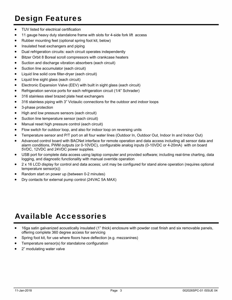
16ga satin galvanized acoustically insulated (1” thick) enclosure with powder coat finish and six removable panels, offering complete 360 degree access for servicing
Spring foot kit, for use where floors have deflection (e.g. mezzanines)
Temperature sensor(s) for standalone configuration
2” modulating water valve
Design Features
Available Accessories
11-Jan-2018 Page 4 002026SPC-01 ISSUE 04
Design Features
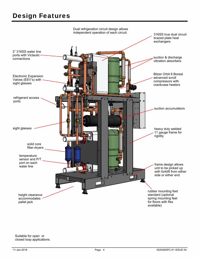
316SS true dual circuit brazed plate heat exchangers
Suitable for open or closed loop applications.
refrigerant access ports
Electronic Expansion Valves (EEV’s) with sight glasses
suction accumulators
suction & discharge vibration absorbers
sight glasses
2” 316SS water line ports with Victaulic connections
frame design allows unit to be picked up with forklift from either side or either end
Dual refrigeration circuit design allows independent operation of each circuit.
Bitzer Orbit 6 Boreal advanced scroll compressors with crankcase heaters
heavy duty welded 11 gauge frame for rigidity
rubber mounting feet standard (optional spring mounting feet for floors with flex available)
height clearance accommodates pallet jack
temperature sensor and P/T port on each water line
solid core filter-dryers
11-Jan-2018 Page 5 002026SPC-01 ISSUE 04
Design Features
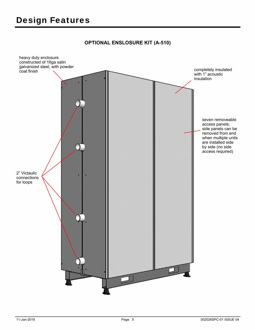
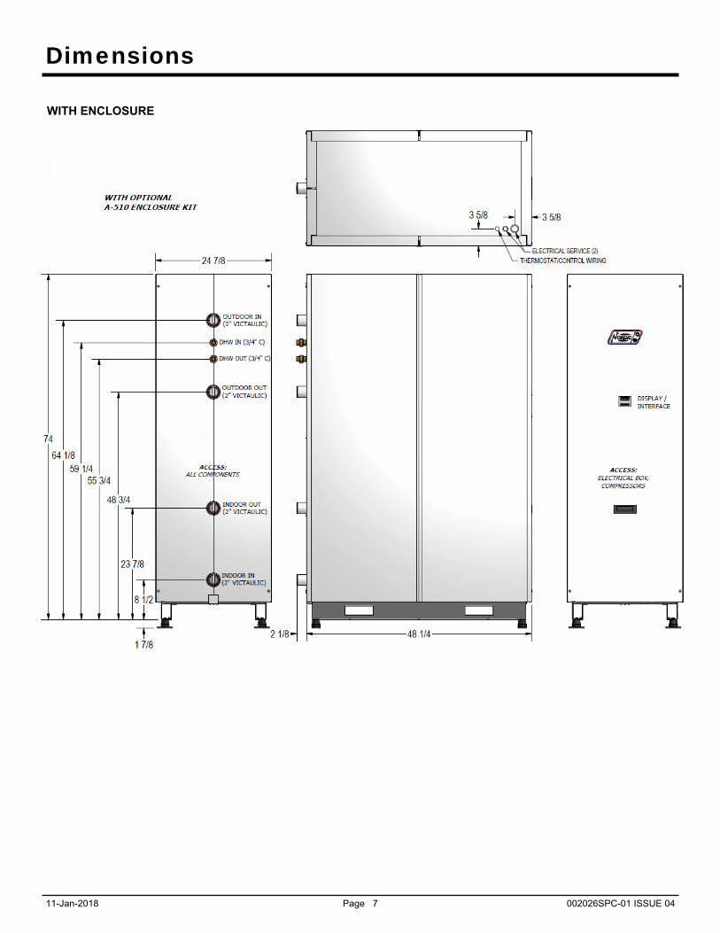
OPTIONAL ENSLOSURE KIT (A-510)
completely insulated with 1” acoustic insulation
seven removeable access panels; side panels can be removed from end when multiple units are installed side by side (no side access required)
2” Victaulic connections for loops
heavy duty enclosure constructed of 16ga satin galvanized steel, with powder coat finish
11-Jan-2018 Page 6 002026SPC-01 ISSUE 04
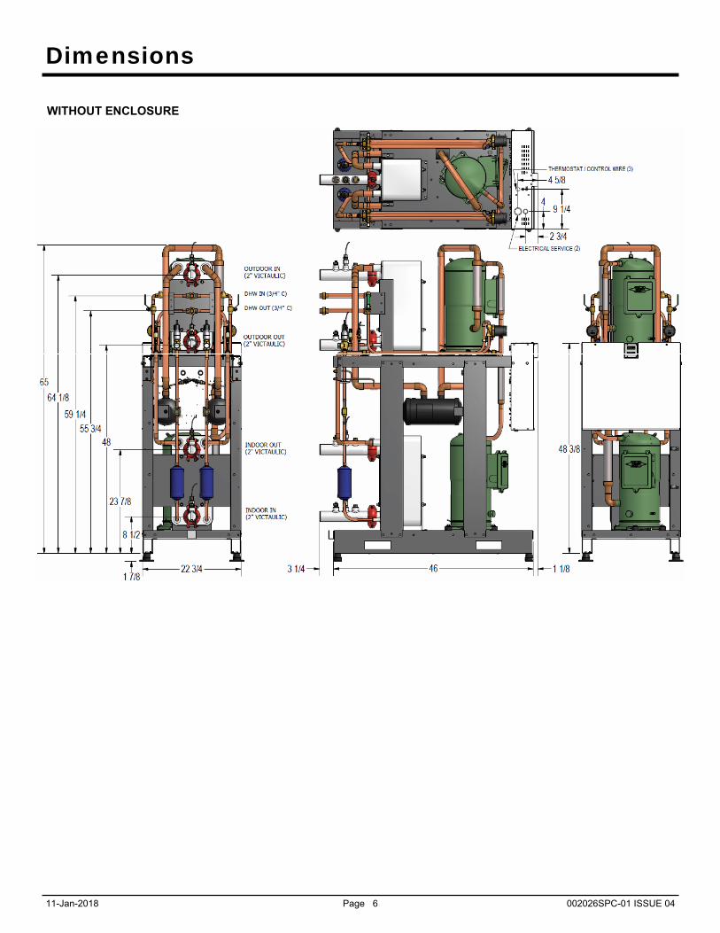
Dimensions
WITHOUT ENCLOSURE
11-Jan-2018 Page 7 002026SPC-01 ISSUE 04
Dimensions
WITH ENCLOSURE

11-Jan-2018 Page 8 002026SPC-01 ISSUE 04
Specifications
Shipping Information
WEIGHT DIMENSIONS in (cm)
lb. (kg) L W H
W-300 1386 (630) 78 (198) 32 (81) 82 (208)
MODEL
Pressure Drops
INDOOR (water 104°F)
OUTDOOR (water 50°F)
OUTDOOR (35% prop. glycol 32°F)
gpm L/s psi kPa psi kPa psi kPa
40 2.5 0.9 6.2 1.0 6.9 2.1 14
48 3.0 1.2 8.3 1.3 9.0 2.5 17
60 3.8 1.8 12 1.9 13 3.1 21
72 4.5 2.6 18 2.7 19 3.7 26
90 5.7 4.0 28 4.1 28 4.8 33
Electrical Information
Power Supply Compressors (each) FLA MCA Maximum
Fuse/Breaker * Minimum Wire Size*
V-ø-Hz MIN MAX RLA LRA Amps Amps Amps ga
4 460-3-60 414 506 25.1 137 50.7 57.0 80 #4-3
5 575-3-60 518 632 21.4 103 43.3 48.7 60 #6-3
* Wire and breaker sizes should be verified by a qualified professional to verify conformance to local codes.
Nomenclature Identifier
2 208-3-60 187 229 49.3 252 99.5 111.8 150 #1-3
Refrigerant Charge (Per Circuit)
MODEL lb kg Oil Type
W-300 11 5.0 PVE-BVC32
- Oil capacity is marked on the compressor label. - Refrigerant charge is subject to revision; actual charge is indicated on the unit nameplate.
Standard Capacity Ratings - Ground Loop Heating* 60Hz EWT 104°F (40°C) ELT 32°F (0°C)
Liquid Flow (Outdoor & Indoor)
Outdoor Pressure Drop*
Indoor Pressure Drop
Input Energy Capacity COPH
gpm L/s psi kPa psi kPa Watts Btu/hr kW W/W
W-300 72 4.6 3.7 26 2.6 18 18,650 231,000 68 3.66
* 35% Propylene Glycol by Volume Outdoor (Ground) Loop Fluid
Model
Standard Capacity Ratings - Ground Water Heating 60Hz EWT 104°F (40°C) ELT 50°F (10°C)
Liquid Flow (Outdoor & Indoor)
Outdoor Pressure Drop
Indoor Pressure Drop
Input Energy Capacity COPH
gpm L/s psi kPa psi kPa Watts Btu/hr kW W/W
W-300 72 4.6 2.7 19 2.6 18 19,360 316,900 93 4.80
Model
Standard Capacity Ratings - Ground Water Cooling 60Hz EWT 53.6°F (12°C) ELT 59°F (15°C)
Liquid Flow (Outdoor & Indoor)
Outdoor Pressure Drop
Indoor Pressure Drop
Input Energy Evap. Capacity COPC EER
gpm L/s psi kPa psi kPa Watts Btu/hr kW W/W Btu/hr/W
W-300 72 4.6 2.7 19 2.7 19 13,330 297,700 87 6.54 22.3
Model
Standard Capacity Ratings - Ground Loop Cooling* 60Hz EWT 53.6°F (12°C) ELT 77°F (25°C)
Liquid Flow (Outdoor & Indoor)
Outdoor Pressure Drop*
Indoor Pressure Drop
Input Energy Evap. Capacity COPC EER
gpm L/s psi kPa psi kPa Watts Btu/hr kW W/W Btu/hr/W
W-300 72 4.6 2.8 19 2.7 19 15,960 272,500 80 5.00 17.1
* 35% Propylene Glycol by Volume Outdoor (Ground) Loop Fluid
Model
11-Jan-2018 Page 9 002026SPC-01 ISSUE 04
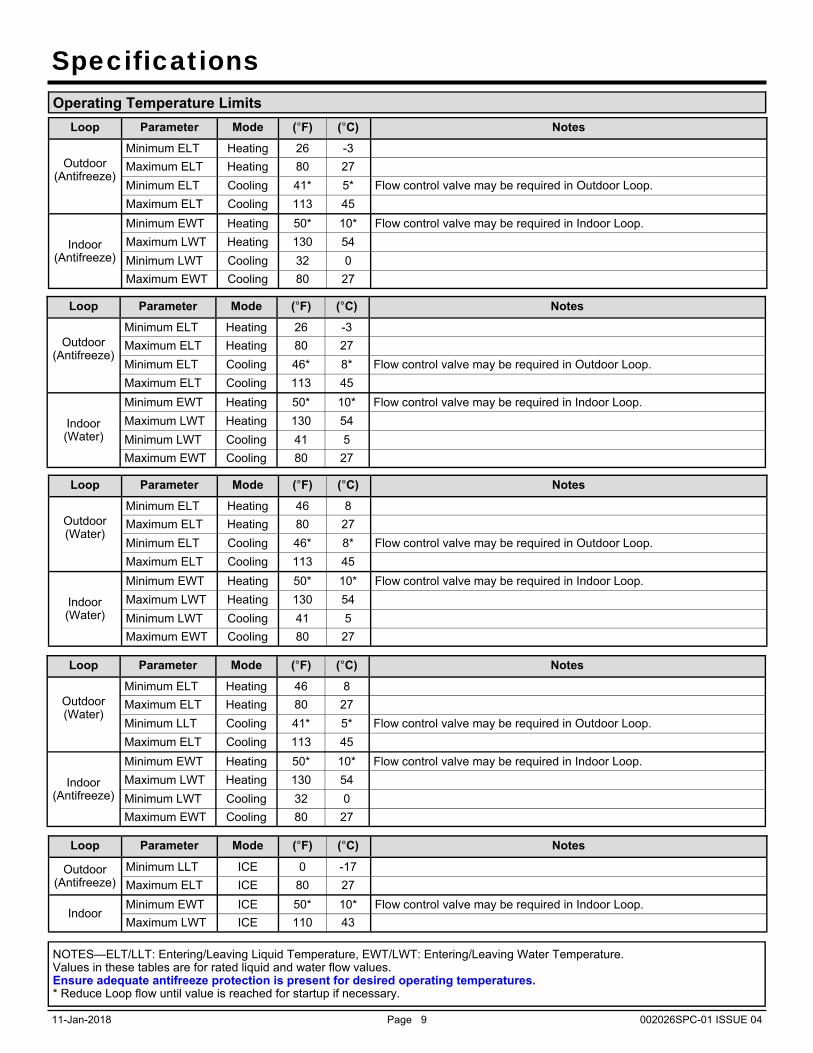
Specifications Operating Temperature Limits
Loop Parameter Mode (°F) (°C) Notes
Outdoor (Antifreeze)
Minimum ELT Heating 26 -3
Maximum ELT Heating 80 27
Minimum ELT Cooling 41* 5* Flow control valve may be required in Outdoor Loop.
Maximum ELT Cooling 113 45
Indoor (Antifreeze)
Minimum EWT Heating 50* 10* Flow control valve may be required in Indoor Loop.
Maximum LWT Heating 130 54
Minimum LWT Cooling 32 0
Maximum EWT Cooling 80 27
NOTES—ELT/LLT: Entering/Leaving Liquid Temperature, EWT/LWT: Entering/Leaving Water Temperature. Values in these tables are for rated liquid and water flow values. Ensure adequate antifreeze protection is present for desired operating temperatures. * Reduce Loop flow until value is reached for startup if necessary.
Loop Parameter Mode (°F) (°C) Notes
Outdoor (Antifreeze)
Minimum ELT Heating 26 -3
Maximum ELT Heating 80 27
Minimum ELT Cooling 46* 8* Flow control valve may be required in Outdoor Loop.
Maximum ELT Cooling 113 45
Indoor (Water)
Minimum EWT Heating 50* 10* Flow control valve may be required in Indoor Loop.
Maximum LWT Heating 130 54
Minimum LWT Cooling 41 5
Maximum EWT Cooling 80 27
Loop Parameter Mode (°F) (°C) Notes
Outdoor (Water)
Minimum ELT Heating 46 8
Maximum ELT Heating 80 27
Minimum LLT Cooling 41* 5* Flow control valve may be required in Outdoor Loop.
Maximum ELT Cooling 113 45
Indoor (Antifreeze)
Minimum EWT Heating 50* 10* Flow control valve may be required in Indoor Loop.
Maximum LWT Heating 130 54
Minimum LWT Cooling 32 0
Maximum EWT Cooling 80 27
Loop Parameter Mode (°F) (°C) Notes
Outdoor (Antifreeze)
Minimum LLT ICE 0 -17
Maximum ELT ICE 80 27
Indoor Minimum EWT ICE 50* 10* Flow control valve may be required in Indoor Loop.
Maximum LWT ICE 110 43
11-Jan-2018 Page 10 002026SPC-01 ISSUE 04
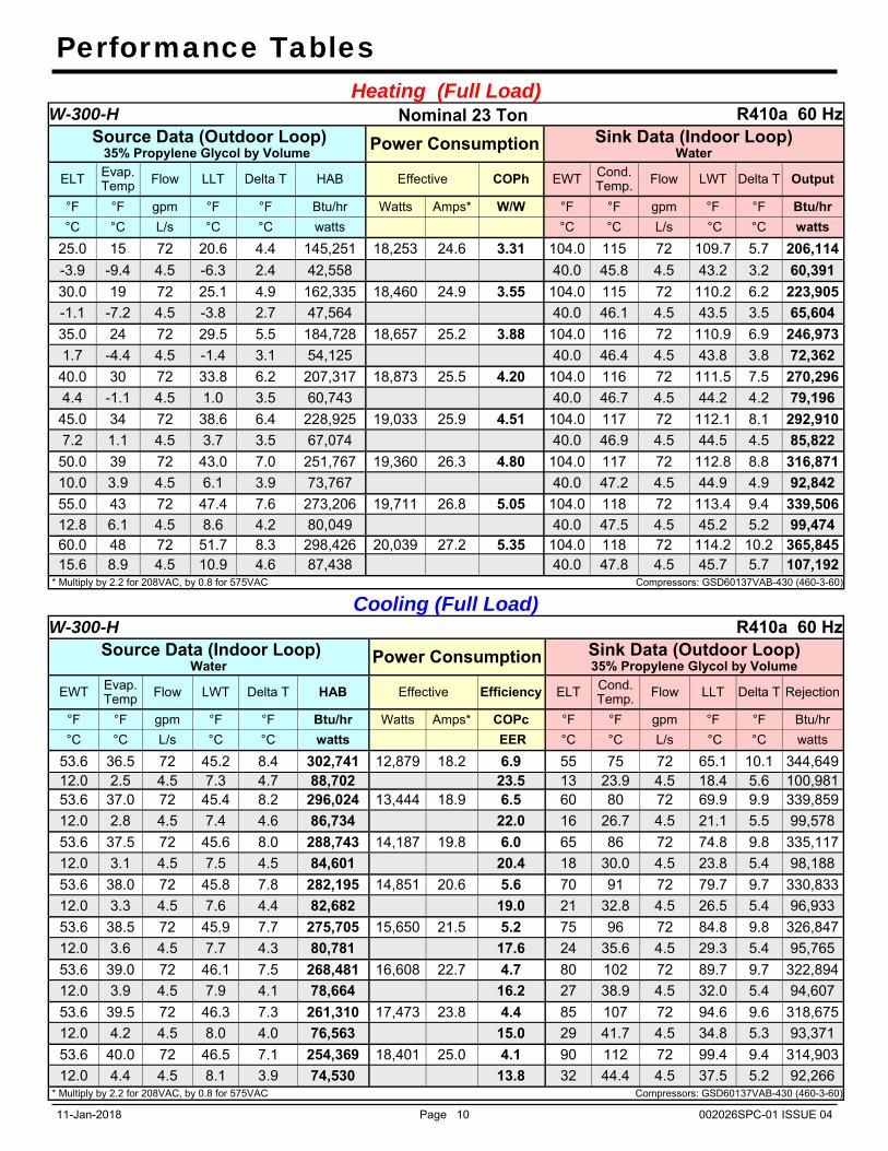
Performance Tables Heating (Full Load)
W-300-H Nominal 23 Ton R410a 60 Hz Source Data (Outdoor Loop)
35% Propylene Glycol by Volume Power Consumption Sink Data (Indoor Loop) Water
ELT Evap. Temp Flow LLT Delta T HAB Effective COPh EWT Cond.
Temp. Flow LWT Delta T Output
°F °F gpm °F °F Btu/hr Watts Amps* W/W °F °F gpm °F °F Btu/hr
°C °C L/s °C °C watts °C °C L/s °C °C watts
25.0 15 72 20.6 4.4 145,251 18,253 24.6 3.31 104.0 115 72 109.7 5.7 206,114
-3.9 -9.4 4.5 -6.3 2.4 42,558 40.0 45.8 4.5 43.2 3.2 60,391
30.0 19 72 25.1 4.9 162,335 18,460 24.9 3.55 104.0 115 72 110.2 6.2 223,905
-1.1 -7.2 4.5 -3.8 2.7 47,564 40.0 46.1 4.5 43.5 3.5 65,604
35.0 24 72 29.5 5.5 184,728 18,657 25.2 3.88 104.0 116 72 110.9 6.9 246,973
1.7 -4.4 4.5 -1.4 3.1 54,125 40.0 46.4 4.5 43.8 3.8 72,362
40.0 30 72 33.8 6.2 207,317 18,873 25.5 4.20 104.0 116 72 111.5 7.5 270,296
4.4 -1.1 4.5 1.0 3.5 60,743 40.0 46.7 4.5 44.2 4.2 79,196
45.0 34 72 38.6 6.4 228,925 19,033 25.9 4.51 104.0 117 72 112.1 8.1 292,910
7.2 1.1 4.5 3.7 3.5 67,074 40.0 46.9 4.5 44.5 4.5 85,822
50.0 39 72 43.0 7.0 251,767 19,360 26.3 4.80 104.0 117 72 112.8 8.8 316,871
10.0 3.9 4.5 6.1 3.9 73,767 40.0 47.2 4.5 44.9 4.9 92,842
55.0 43 72 47.4 7.6 273,206 19,711 26.8 5.05 104.0 118 72 113.4 9.4 339,506
12.8 6.1 4.5 8.6 4.2 80,049 40.0 47.5 4.5 45.2 5.2 99,474 60.0 48 72 51.7 8.3 298,426 20,039 27.2 5.35 104.0 118 72 114.2 10.2 365,845 15.6 8.9 4.5 10.9 4.6 87,438 40.0 47.8 4.5 45.7 5.7 107,192
* Multiply by 2.2 for 208VAC, by 0.8 for 575VAC Compressors: GSD60137VAB-430 (460-3-60)
Cooling (Full Load) W-300-H R410a 60 Hz
Source Data (Indoor Loop) Water Power Consumption Sink Data (Outdoor Loop)
35% Propylene Glycol by Volume
EWT Evap. Temp Flow LWT Delta T HAB Effective Efficiency ELT Cond.
Temp. Flow LLT Delta T Rejection
°F °F gpm °F °F Btu/hr Watts Amps* COPc °F °F gpm °F °F Btu/hr
°C °C L/s °C °C watts EER °C °C L/s °C °C watts
53.6 36.5 72 45.2 8.4 302,741 12,879 18.2 6.9 55 75 72 65.1 10.1 344,649 12.0 2.5 4.5 7.3 4.7 88,702 23.5 13 23.9 4.5 18.4 5.6 100,981 53.6 37.0 72 45.4 8.2 296,024 13,444 18.9 6.5 60 80 72 69.9 9.9 339,859
12.0 2.8 4.5 7.4 4.6 86,734 22.0 16 26.7 4.5 21.1 5.5 99,578
53.6 37.5 72 45.6 8.0 288,743 14,187 19.8 6.0 65 86 72 74.8 9.8 335,117
12.0 3.1 4.5 7.5 4.5 84,601 20.4 18 30.0 4.5 23.8 5.4 98,188
53.6 38.0 72 45.8 7.8 282,195 14,851 20.6 5.6 70 91 72 79.7 9.7 330,833
12.0 3.3 4.5 7.6 4.4 82,682 19.0 21 32.8 4.5 26.5 5.4 96,933
53.6 38.5 72 45.9 7.7 275,705 15,650 21.5 5.2 75 96 72 84.8 9.8 326,847
12.0 3.6 4.5 7.7 4.3 80,781 17.6 24 35.6 4.5 29.3 5.4 95,765
53.6 39.0 72 46.1 7.5 268,481 16,608 22.7 4.7 80 102 72 89.7 9.7 322,894
12.0 3.9 4.5 7.9 4.1 78,664 16.2 27 38.9 4.5 32.0 5.4 94,607
53.6 39.5 72 46.3 7.3 261,310 17,473 23.8 4.4 85 107 72 94.6 9.6 318,675
12.0 4.2 4.5 8.0 4.0 76,563 15.0 29 41.7 4.5 34.8 5.3 93,371
53.6 40.0 72 46.5 7.1 254,369 18,401 25.0 4.1 90 112 72 99.4 9.4 314,903
12.0 4.4 4.5 8.1 3.9 74,530 13.8 32 44.4 4.5 37.5 5.2 92,266 * Multiply by 2.2 for 208VAC, by 0.8 for 575VAC Compressors: GSD60137VAB-430 (460-3-60)

11-Jan-2018 Page 11 002026SPC-01 ISSUE 04
Performance Tables
ICE Cooling Full Load W-300-H R410a 60 Hz
Source Data (Outdoor Loop) 50% Propylene Glycol by Volume Power Consumption Sink Data (Indoor Loop)
Water
ELT Evap. Temp Flow LLT Delta T HAB COPc
EER Effective COPh EWT Cond. Temp. Flow LWT Delta T Output
°F °F gpm °F °F Btu/hr W/W Watts Amps* W/W °F °F gpm °F °F Btu/hr
°C °C L/s °C °C watts Btu/hr/W °C °C L/s °C °C watts
5.0 -3 72.0 1.9 3.1 97,726 1.89 15,127 20.1 2.83 85.0 94 72.0 89.1 4.1 146,114
-15.0 -19.4 4.542 -16.7 1.7 28,634 6.5 29.4 34.4 4.542 31.7 2.3 42,811
10.0 2 72.0 6.5 3.5 109,561 2.09 15,394 20.4 3.02 85.0 95 72.0 89.4 4.4 158,860
-12.2 -16.7 4.542 -14.2 1.9 32,101 7.1 29.4 35.0 4.542 31.9 2.5 46,546
15.0 7 72.0 11.1 3.9 122,020 2.29 15,646 20.7 3.22 85.0 96 72.0 89.8 4.8 172,178
-9.4 -13.9 4.542 -11.6 2.2 35,752 7.8 29.4 35.6 4.542 32.1 2.7 50,448 20.0 12 72.0 15.7 4.3 135,425 2.50 15,889 21.0 3.44 85.0 97 72.0 90.2 5.2 186,411 -6.7 -11.1 4.542 -9.1 2.4 39,679 8.5 29.4 36.1 4.542 32.3 2.9 54,618
* Multiply by 2.2 for 208VAC, by 0.8 for 575VAC Compressors: GSD60137VAB-521 (460-3-60)
11-Jan-2018 Page 12 002026SPC-01 ISSUE 04

11-Jan-2018 Page 13 002026SPC-01 ISSUE 04
11-Jan-2018 Page 14 002026SPC-01 ISSUE 04

11-Jan-2018 Page 15 002026SPC-01 ISSUE 04

11-Jan-2018 Page 16 002026SPC-01 ISSUE 04
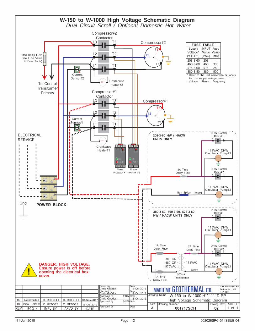
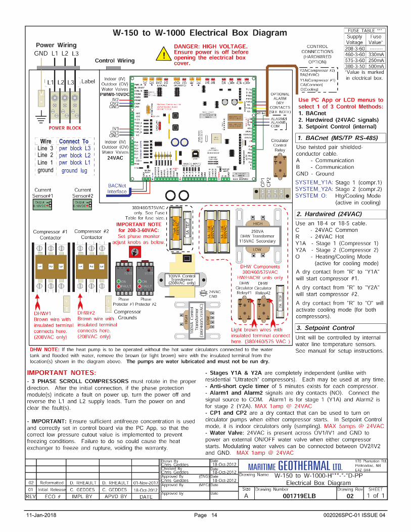
The BACnet interface is an MS/TP connection via RS-485 twisted pair. There is a termination jumper if required to terminate the con-nection. It is located just above the BACnet connector, marked as TERM on the control board. The connector on the control board is a three wire removable screw connector. The signals are as follows: A: Communications line (+) (right pin) B: Communications line (-) (middle pin) C: Ground connection (left pin) Vendor: Maritime Geothermal Ltd. Vendor ID: 260 Model Name: MGT GEN2 Control Board
The following parameters can be set via the LED Display Configuration Menu or via the PC APP Configuration Page.
1) Baud rate 2) Instance number 3) MAC address
The data is available regardless of the selected control method. In order to control the unit via the BACnet interface, set the Control Source to BACnet either by using the PC APP configuration page or the display menus.
The following tables provide a list of the objects applicable to this model series, along with a description of each. Note that there may be other objects available that do not apply to this model.
BACnet Interface
BACnet OBJECTS - CONTROL SIGNALS (READ/WRITE)
Name Data Type ID Property Description
SYSTEM_Y1A Binary Value BV0 Present Value Stage 1 - bottom compressor (active is on)
SYSTEM_Y2A Binary Value BV1 Present Value Stage 2 - top compressor (active is on)
BACnet_Units Binary Value BV9 Present Value Select the units to use for the BACnet objects
Note: object names may be subject to change without prior notice.

11-Jan-2018 Page 17 002026SPC-01 ISSUE 04
BACnet OBJECTS - DATA (READ ONLY)
Name Data Type ID Property Units Description
LPS1 Analog Input AI6 Present Value PSIG (kPa) Stage 1 Low pressure value (suction pressure)
HPS1 Analog Input AI7 Present Value PSIG (kPa) Stage 1 High pressure value (discharge pressure)
EVAP1 Analog Input AI8 Present Value degF (degC) Stage 1 Evaporating Temperature
COND1 Analog Input AI9 Setpoint Value degF (degC) Stage 1 Condensing Temperature
Suction_Line1 Analog Input AI10 Present Value degF (degC) Stage 1 Suction line temperature
Superheat1 Analog Input AI11 Setpoint Value degF (degC) Stage 1 Superheat
EEV1_POS Analog Input AI12 Present Value % Stage 1 EEV position (% open)
LPS2 Analog Input AI13 Present Value PSIG (kPa) Stage 2 Low pressure value (suction pressure)
HPS2 Analog Input AI14 Present Value PSIG (kPa) Stage 2 High pressure value (discharge pressure)
EVAP2 Analog Input AI15 Present Value degF (degC) Stage 2 Evaporating Temperature
COND2 Analog Input AI16 Setpoint Value degF (degC) Stage 2 Condensing Temperature
Suction_Line2 Analog Input AI17 Present Value degF (degC) Stage 2 Suction line temperature
Superheat2 Analog Input AI18 Setpoint Value degF (degC) Stage 2 Superheat
EEV2_POS Analog Input AI19 Present Value % Stage 2 EEV position (% open)
Outside_Temp Analog Input AI20 Present Value degF (degC) Outdoor Ambient temperature—ACCESSORY
O_IN Analog Input AI21 Present Value degF (degC) Indoor IN temperature
O_OUT Analog Input AI22 Present Value degF (degC) Indoor OUT temperature
I_IN Analog Input AI23 Present Value degF (degC) Indoor IN temperature
I_OUT Analog Input AI24 Present Value degF (degC) Indoor OUT temperature
Comp1_Current Analog Input AI0 Present Value A Stage1 compressor current draw (AI0)
Comp2_Current Analog Input AI1 Present Value A Stage2 compressor current draw (AI1)
AI_2 Analog Input AI2 Present Value User Selectable User defined (0-5VDC or 4-20mA)
AI_3 Analog Input AI3 Present Value User Selectable User defined (0-5VDC or 4-20mA)
AI_4 Analog Input AI4 Present Value User Selectable User defined (0-5VDC or 4-20mA)
AI_5 Analog Input AI5 Present Value User Selectable User defined (0-5VDC or 4-20mA)
PWM_IN Analog Value AV0 Present Value % PWM input (from external source)
PWM1 Analog Value AV1 Present Value % PWM output value (spare)
PWM2 Analog Value AV2 Present Value % PWM output value (spare)
PWM3 Analog Value AV3 Present Value % OV2 - PWM or 0-10VDC for Outdoor Loop water valve
PWM4 Analog Value AV4 Present Value % IV2 - PWM or 0-10VDC for Indoor Loop water valve
STAGE1 Binary Output BO0 Present Value N/A Compressor#1 contactor
STAGE2 Binary Output BO1 Present Value N/A Compressor#2 contactor
ICR Binary Output BO2 Present Value N/A Indoor circulator control
DO_0 Binary Output BO3 Present Value N/A OV1 (for 24VAC Outdoor Loop water valve)
DO_1 Binary Output BO4 Present Value N/A IV1 (for 24VAC Indoor Loop water valve)
HYD_AUX Binary Output BO5 Present Value N/A Hydronic Auxiliary
DO_3 Binary Output BO6 Present Value N/A Hydronic Auxiliary Only (without compressor)
PHS_1 Binary Output BO7 Present Value N/A Dry contact lockout pin for Stage 1
PHS_2 Binary Output BO8 Present Value N/A Dry contact lockout pin for Stage 2
Outdoor Flow Binary Value BV10 Present Value N/A Outdoor Loop flow switch
Indoor Flow Binary Value BV11 Present Value N/A Indoor Loop flow switch
Phase Monitor1 Binary Value BV12 Present Value N/A Phase Monitor Stage 1
Phase Monitor2 Binary Value BV13 Present Value N/A Phase Monitor Stage 2 Comp_Monitor1 Binary Value BV14 Present Value N/A Compressor Monitor Stage 1
Comp_Monitor2 Binary Value BV15 Present Value N/A Compressor Monitor Stage 2
Note: available objects may be subject to change without prior notice.
11-Jan-2018 Page 18 002026SPC-01 ISSUE 04
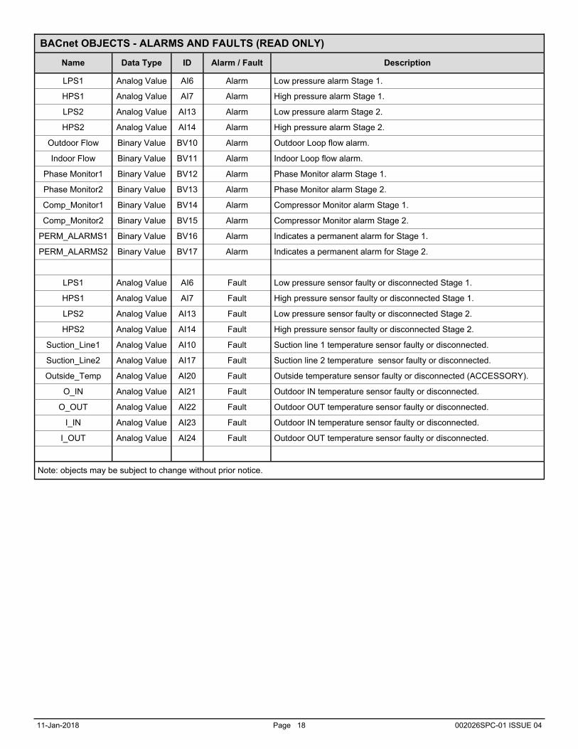
BACnet OBJECTS - ALARMS AND FAULTS (READ ONLY)
Name Data Type ID Alarm / Fault Description
LPS1 Analog Value AI6 Alarm Low pressure alarm Stage 1.
HPS1 Analog Value AI7 Alarm High pressure alarm Stage 1.
LPS2 Analog Value AI13 Alarm Low pressure alarm Stage 2.
HPS2 Analog Value AI14 Alarm High pressure alarm Stage 2.
Outdoor Flow Binary Value BV10 Alarm Outdoor Loop flow alarm.
Indoor Flow Binary Value BV11 Alarm Indoor Loop flow alarm.
Phase Monitor1 Binary Value BV12 Alarm Phase Monitor alarm Stage 1.
Phase Monitor2 Binary Value BV13 Alarm Phase Monitor alarm Stage 2.
Comp_Monitor1 Binary Value BV14 Alarm Compressor Monitor alarm Stage 1.
Comp_Monitor2 Binary Value BV15 Alarm Compressor Monitor alarm Stage 2.
PERM_ALARMS1 Binary Value BV16 Alarm Indicates a permanent alarm for Stage 1.
PERM_ALARMS2 Binary Value BV17 Alarm Indicates a permanent alarm for Stage 2.
LPS1 Analog Value AI6 Fault Low pressure sensor faulty or disconnected Stage 1.
HPS1 Analog Value AI7 Fault High pressure sensor faulty or disconnected Stage 1.
LPS2 Analog Value AI13 Fault Low pressure sensor faulty or disconnected Stage 2.
HPS2 Analog Value AI14 Fault High pressure sensor faulty or disconnected Stage 2.
Suction_Line1 Analog Value AI10 Fault Suction line 1 temperature sensor faulty or disconnected.
Suction_Line2 Analog Value AI17 Fault Suction line 2 temperature sensor faulty or disconnected.
Outside_Temp Analog Value AI20 Fault Outside temperature sensor faulty or disconnected (ACCESSORY).
O_IN Analog Value AI21 Fault Outdoor IN temperature sensor faulty or disconnected.
O_OUT Analog Value AI22 Fault Outdoor OUT temperature sensor faulty or disconnected.
I_IN Analog Value AI23 Fault Outdoor IN temperature sensor faulty or disconnected.
I_OUT Analog Value AI24 Fault Outdoor OUT temperature sensor faulty or disconnected.
Note: objects may be subject to change without prior notice.
11-Jan-2018 Page 19 002026SPC-01 ISSUE 04
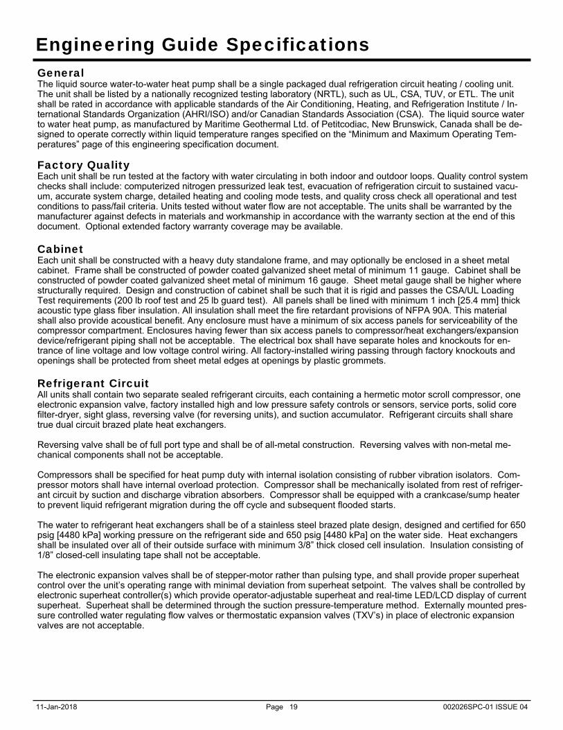
Engineering Guide Specifications General The liquid source water-to-water heat pump shall be a single packaged dual refrigeration circuit heating / cooling unit. The unit shall be listed by a nationally recognized testing laboratory (NRTL), such as UL, CSA, TUV, or ETL. The unit shall be rated in accordance with applicable standards of the Air Conditioning, Heating, and Refrigeration Institute / In-ternational Standards Organization (AHRI/ISO) and/or Canadian Standards Association (CSA). The liquid source water to water heat pump, as manufactured by Maritime Geothermal Ltd. of Petitcodiac, New Brunswick, Canada shall be de-signed to operate correctly within liquid temperature ranges specified on the “Minimum and Maximum Operating Tem-peratures” page of this engineering specification document. Factory Quality Each unit shall be run tested at the factory with water circulating in both indoor and outdoor loops. Quality control system checks shall include: computerized nitrogen pressurized leak test, evacuation of refrigeration circuit to sustained vacu-um, accurate system charge, detailed heating and cooling mode tests, and quality cross check all operational and test conditions to pass/fail criteria. Units tested without water flow are not acceptable. The units shall be warranted by the manufacturer against defects in materials and workmanship in accordance with the warranty section at the end of this document. Optional extended factory warranty coverage may be available. Cabinet Each unit shall be constructed with a heavy duty standalone frame, and may optionally be enclosed in a sheet metal cabinet. Frame shall be constructed of powder coated galvanized sheet metal of minimum 11 gauge. Cabinet shall be constructed of powder coated galvanized sheet metal of minimum 16 gauge. Sheet metal gauge shall be higher where structurally required. Design and construction of cabinet shall be such that it is rigid and passes the CSA/UL Loading Test requirements (200 lb roof test and 25 lb guard test). All panels shall be lined with minimum 1 inch [25.4 mm] thick acoustic type glass fiber insulation. All insulation shall meet the fire retardant provisions of NFPA 90A. This material shall also provide acoustical benefit. Any enclosure must have a minimum of six access panels for serviceability of the compressor compartment. Enclosures having fewer than six access panels to compressor/heat exchangers/expansion device/refrigerant piping shall not be acceptable. The electrical box shall have separate holes and knockouts for en-trance of line voltage and low voltage control wiring. All factory-installed wiring passing through factory knockouts and openings shall be protected from sheet metal edges at openings by plastic grommets. Refrigerant Circuit All units shall contain two separate sealed refrigerant circuits, each containing a hermetic motor scroll compressor, one electronic expansion valve, factory installed high and low pressure safety controls or sensors, service ports, solid core filter-dryer, sight glass, reversing valve (for reversing units), and suction accumulator. Refrigerant circuits shall share true dual circuit brazed plate heat exchangers. Reversing valve shall be of full port type and shall be of all-metal construction. Reversing valves with non-metal me-chanical components shall not be acceptable. Compressors shall be specified for heat pump duty with internal isolation consisting of rubber vibration isolators. Com-pressor motors shall have internal overload protection. Compressor shall be mechanically isolated from rest of refriger-ant circuit by suction and discharge vibration absorbers. Compressor shall be equipped with a crankcase/sump heater to prevent liquid refrigerant migration during the off cycle and subsequent flooded starts. The water to refrigerant heat exchangers shall be of a stainless steel brazed plate design, designed and certified for 650 psig [4480 kPa] working pressure on the refrigerant side and 650 psig [4480 kPa] on the water side. Heat exchangers shall be insulated over all of their outside surface with minimum 3/8” thick closed cell insulation. Insulation consisting of 1/8” closed-cell insulating tape shall not be acceptable. The electronic expansion valves shall be of stepper-motor rather than pulsing type, and shall provide proper superheat control over the unit’s operating range with minimal deviation from superheat setpoint. The valves shall be controlled by electronic superheat controller(s) which provide operator-adjustable superheat and real-time LED/LCD display of current superheat. Superheat shall be determined through the suction pressure-temperature method. Externally mounted pres-sure controlled water regulating flow valves or thermostatic expansion valves (TXV’s) in place of electronic expansion valves are not acceptable.
11-Jan-2018 Page 20 002026SPC-01 ISSUE 04
The suction accumulators shall be insulated with minimum 3/8” thick closed cell insulation to prevent condensation. The accumulator’s internal oil return port shall be sized properly for the unit’s operating range. To ensure proper oil return, suction accumulator shall not be ‘oversized’. Piping and Connections The unit shall have two sets of primary water in and water out connections (outdoor and indoor). The primary connec-tion type shall be 3” stainless steel pipe for Victaulic connection. All internal water and refrigerant piping shall be insulated with minimum 3/8” thick closed cell insulation. Insulation con-sisting of 1/8” closed-cell insulating tape shall not be acceptable. Electrical Controls and safety devices shall be factory wired and mounted within the unit. Controls shall include 24 volt alternating current (24VAC) activated compressor contactors, reversing valves, and 24VAC 100VA transformer with built in circuit breaker or fused on both primary and secondary sides. Units shall be name-plated for use with time delay fuses or cir-cuit breakers. Unit controls shall be 24VAC and provide heating or cooling as required by the remote thermostat or con-troller. 3-phase protection shall be present in each unit to protect the compressor against loss of phase and reverse rota-tion. 3-phase protection shall be factory installed. Unit shall have dry contacts for controlling loop circulating pumps via an external 24VAC contactor. Unit shall provide remote fault indication to the control system via serial communication and fault messages on front panel LCD display. Unit Control The control system shall have the following features: 1. Anti-short cycle time delay on compressor operation. Time delay shall be a minimum of 5 minutes, for both thermo-
stat demand and safety control reset starts. An override shall be provided to disable this delay for unit commission-ing and testing purposes.
2. Random compressor start delay of 0-120 seconds on unit power up to facilitate starting multiple units after a power failure.
3. Flow switch on outdoor loop, and also on indoor loop for reversing units. 4. Compressor shutdown for high or low refrigerant pressures, low flow conditions and for phase protection faults. 5. Automatic intelligent reset: unit shall automatically restart 5 minutes after trip if the fault has cleared. Should a fault
reoccur 3 times sequentially then permanent lockout shall occur, requiring cycling of the power to the unit in order to reset.
6. Manual reset high pressure in case of electronic board failure. 7. The low pressure shall not be monitored for the first 90 seconds after a compressor start to prevent nuisance safety
trips. 8. 2 x 16 backlit Liquid Crystal Display (LCD) and four buttons for limited data access. Unit may be configured for
stand alone operation with optional temperature sensor(s) 9. Universal Serial Bus (USB) port for full data access and diagnostic information, including real-time charting and
data-logging Maritime Geothermal works continually to improve its products. As a result, the design and specifications of any product may be changed without notice. Please contact Maritime Geothermal at 1-506-756-8135 or visit www.nordicghp.com for latest design and specifications. Purchaser’s approval of this data set signifies that the equipment is acceptable un-der the provisions of the job specification. Statements and other information contained herein are not express warran-ties and do not form the basis of any commercial contract or other agreement between any parties, but are merely Mari-time Geothermal’s statement of opinion regarding its products.
11-Jan-2018 Page 21 002026SPC-01 ISSUE 04
LIMITED WARRANTY
MARITIME GEOTHERMAL LTD. warrants that its commercial geothermal heat pumps shall be free from defects in materials and workmanship for a period of ONE (1) YEAR after the date of installation or for a period of ONE (1) YEAR AND SIXTY (60) DAYS after the date of shipment, whichever occurs first. This warranty covers all internal components of the heat pump. MARITIME GEOTHERMAL LTD. shall, at its option, repair or replace any part covered by this warranty. Defective parts shall be returned to MARITIME GEOTHERMAL LTD., transportation charges prepaid. Replacement of repaired parts and components are warranted only for the remaining portion of the original warranty period.
This warranty is subject to the following conditions:
1. The geothermal heat pump(s) must be properly installed and maintained in accordance with MARITIME GEOTHERMAL LTD.’s guidelines. Improper installation includes but is not limited to the following conditions: Indoor or outdoor loop flow lower than listed in engineering specification or as expressly
approved by MARITIME GEOTHERMAL LTD. Operating the heat pump either manually or with automated controls so that the unit is forced to
function outside its normal operating range or in a fashion which directly or indirectly leads to failure of components or the entire heat pump
Disabling of safety controls Insufficient loop antifreeze concentration for loop temperature, or antifreeze concentration
incorrectly set in control board Fouled heat exchangers due to poor water quality Failure to use strainers or clean them regularly Impact or physical damage sustained by the heat pump Poor refrigeration maintenance practices, including brazing without nitrogen flow, or using wrong
braze/flux Incorrect voltage or missing phase supplied to unit Unit modified electrically or mechanically from factory supplied condition Water quality outside of recommended limits (e.g. salinity or pH) Unit not mounted with supplied anti-vibration grommets or optional spring feet Corrosion damage due to corrosive ambient environment Failure due to excessive cycling caused by improper mechanical setup or improperly
programmed external controller Physical loads or pressures placed on unit from external equipment
2. The installer must complete the Startup Record and return it to MARITIME GEOTHERMAL LTD. within 21 days of unit installation.
3. For new construction, it is the responsibility of the building or general contractor to supply temporary heat to the structure prior to occupancy. Geothermal heat pumps are designed to provide heat only to the completely finished and insulated structure. Startup of the unit shall not be scheduled prior to completion of construction and final duct installation for validation of this warranty.
4. It is the customer's responsibility to supply the proper quantity and quality of water or properly sized ground loop with adequate freeze protection.
MARITIME GEOTHERMAL LTD.'s sole and exclusive liability shall be, at its option, to repair or replace any part or component which is returned by the customer during the applicable warranty period set forth above, provided that (1) MARITIME GEOTHERMAL LTD. is promptly notified in writing upon discovery by the customer that such part or component fails or is defective (2) the customer returns such part or component to MARITIME GEOTHERMAL LTD., transportation charges prepaid, within (30) thirty days of failure, and (3) MARITIME GEOTHERMAL LTD.'s examination of such component discloses to its satisfaction that such part or component has failed or is defective and was not caused by one of the circumstances listed above. MARITIME GEOTHERMAL LTD. will not be responsible for any consequential damages or labour costs incurred. In additional, MARITIME GEOTHERMAL LTD. will not be responsible for the cost of replacement parts purchased from a third party.