0027/nd guidelines for marine lifting and lowering...
TRANSCRIPT

TECHNICAL STANDARDS COMMITTEE
http://www.dnvgl.com/
GUIDELINES FOR MARINE LIFTING & LOWERING OPERATIONS
8 Jul 16 11.2 RLJ Replaced by DNVGL-ST-N001
14 Dec 15 11 MJR Technical Standards Committee
22 Jun 13 10 MJR Technical Policy Board
31 Mar 10 9 GPB Technical Policy Board
23 Jun 09 8 GPB Technical Policy Board
15 Apr 09 7 GPB Technical Policy Board
19 Jan 09 6 GPB Technical Policy Board
17 Feb 06 5 RLJ Technical Policy Board
30 Nov 05 4 JR Technical Policy Board
15 Oct 02 3 JR Technical Policy Board
01 May 02 2 JR Technical Policy Board
11 Aug 93 1 JR Technical Policy Board
31 Oct 90 0 JR Technical Policy Board
Date Revision Prepared by Authorised by
This document has been replaced by the standard DNVGL-ST-N001
which may be retrieved through https://my.dnvgl.com/ This document may still be valid for some existing projects.
This Guideline was updated as part of the first stage of the harmonisation between the GL Noble Denton and DNV heritage marine services requirements.
Various minor anomalies and errors were introduced into this guideline including some links to the associated 0001/ND. These have all been rectified in DNV-ST-N001 which now replaces both guidelines. DNVGL-ST-N001
should be referenced if there are any queries when 0027/ND is used in the change-over period.
Refer also to DNVGL-SE-0080 Noble Denton marine services – Marine Warranty Survey for further details.
All references to GL Noble Denton apply to the legal entity trading under the DNV GL or GL Noble Denton name which is contracted to carry out the scope of work and issues a Certificate of Approval, or provides a marine
related advisory or assurance service.
Once downloaded this document becomes UNCONTROLLED.
0027/ND
GUIDELINES FOR MARINE LIFTING & LOWERING OPERATIONS
0027/ND Rev 11 Page 2 of 84
PREFACE
This document has been drawn with care to address what are considered to be the primary issues in relation to the contents based on the experience of the GL Noble Denton Group of Companies (“the Group”). This should not, however, be taken to mean that this document deals comprehensively with all of the issues which will need to be addressed or even, where a particular matter is addressed, that this document sets out a definitive view for all situations. In using this document, it should be treated as giving guidelines for sound and prudent practice, but guidelines must be reviewed in each particular case by the responsible organisation in each project to ensure that the particular circumstances of that project are addressed in a way which is adequate and appropriate to ensure that the overall guidance given is sound and comprehensive.
Reasonable precaution has been taken in the preparation of this document to seek to ensure that the content is correct and error free. However, no company in the Group
shall be liable for any loss or damage incurred resulting from the use of the information contained herein or
shall voluntarily assume a responsibility in tort to any party or
shall owe a duty of care to any party other than to its contracting customer entity (subject always to the terms of contract between such Group company and subcontracting customer entity).
This document must be read in its entirety and is subject to any assumptions and qualifications expressed therein as well as in any other relevant communications by the Group in connection with it. Elements of this document contain detailed technical data which is intended for analysis only by persons possessing requisite expertise in its subject matter.
© 2015 Noble Denton Group Limited. The content of this document is the copyright of Noble Denton Group Limited. All rights reserved. Any reproduction in other material must have written permission. Extracts may be reproduced provided that their origin is clearly referenced.

GUIDELINES FOR MARINE LIFTING & LOWERING OPERATIONS
0027/ND Rev 11 Page 3 of 84
CONTENTS SECTION PAGE NO.
1 SUMMARY 6
2 INTRODUCTION 7
3 DEFINITIONS & ABBREVIATIONS 12
4 THE APPROVAL PROCESS 18 4.1 GL Noble Denton approval 18 4.2 Scope of work leading to an approval 18 4.3 Approval of moorings 19 4.4 Limitation of approval 19 4.5 Surveys 20
5 LOAD AND SAFETY FACTORS 21 5.1 Introduction 21 5.2 Weight contingency & centre of gravity factors 23 5.3 Module tilt for single crane lifts 23 5.4 2-Hook lift factors 23 5.5 Dynamic amplification factors 24 5.6 Skew load factor (SKL) 25 5.7 Additional factors 27 5.8 2-Part sling factor 27 5.9 Lift stability 27
6 DERIVATION OF HOOK, LIFT POINT, AND RIGGING LOADS 28 6.1 Introduction 28 6.2 Hook loads 28 6.3 Lift point loads 29 6.4 Sling loads 29
7 SLING AND GROMMET DESIGN 31 7.1 Introduction 31 7.2 Sling or grommet design 31 7.3 Sling or grommet nominal safety factors for design 31 7.4 Load factor f 32 7.5 Consequence factor c 32 7.6 Sling or grommet reduction factor r 32 7.7 Termination factor s 32 7.8 Bending factor b 33 7.9 Wear and application factor w 34 7.10 Material factor m 34 7.11 Twist factor tw 34
8 SHACKLE DESIGN 35 8.1 Introduction 35 8.2 Design considerations 35
9 OTHER LIFTING EQUIPMENT DESIGN 36 9.1 Introduction 36 9.2 Lifting tools 36 9.3 Spreader bars and spreader frames 36 9.4 Other lifting equipment 36 9.5 Fibre rope reployment systems 36
10 THE CRANE AND INSTALLATION VESSEL 38 10.1 Introduction 38 10.2 Cranes 38 10.3 Hook load 38 10.4 Heave compensation 38
GUIDELINES FOR MARINE LIFTING & LOWERING OPERATIONS
0027/ND Rev 11 Page 4 of 84
10.5 Installation vessel 39 10.6 DP systems (if applicable) 39 10.7 Mooring systems (if applicable) 39
11 STRUCTURAL CALCULATIONS 40 11.1 Codes and specifications 40 11.2 Load cases and structural modelling 40 11.3 Structure 40 11.4 Consequence factors 40 11.5 Lift points 40 11.6 Spreader bars, frames & other structural items of lifting equipment 41 11.7 Allowable stresses 41 11.8 Independent analysis 41
12 LIFT POINT DESIGN 42 12.1 Introduction 42 12.2 General design requirements 42 12.3 Lateral lift point load 42 12.4 Sling ovalisation 42 12.5 Padeyes 43 12.6 Cast Padears and welded trunnions 43 12.7 Inspection of lift points 43
13 FABRICATION YARD LIFTS 45 13.1 Introduction 45 13.2 Weight and CoG 45 13.3 Additional loads 45 13.4 Dynamic loads 45 13.5 Load cases 46 13.6 Lifting equipment 46 13.7 Fabrication yard cranes 46 13.8 Operational and practical considerations for onshore lifts 46
14 FABRICATION OF RIGGING AND LIFTING EQUIPMENT 48 14.1 Introduction 48 14.2 Materials and construction of steel slings and grommets 48 14.3 Materials and construction of fibre slings and grommets 48 14.4 Materials and construction of shackles 49 14.5 Materials and construction of lifting tools 49 14.6 Materials and construction of spreader bars and spreader frames 50 14.7 Materials and construction of other lifting equipment 51
15 CERTIFICATION AND INSPECTION OF RIGGING AND LIFTING EQUIPMENT 52 15.1 Introduction 52 15.2 Certification, inspection and revalidation of slings and grommets 52 15.3 Certification and Inspection of shackles 54 15.4 Certification and Inspection of lifting tools 55 15.5 Certification and Inspection of spreader bars and spreader frames 55 15.6 Certification and Inspection of other lifting equipment 55
16 CLEARANCES 57 16.1 Introduction 57 16.2 Clearances around lifted object (floating crane) 57 16.3 Clearances around lifted object (jacked-up crane) 57 16.4 Clearances around crane vessel 58 16.5 Clearances around mooring lines and anchors 58 16.6 Clearances for fabrication yard lifts 58
17 BUMPERS AND GUIDES 59 17.1 Introduction 59 17.2 Module movement 59
GUIDELINES FOR MARINE LIFTING & LOWERING OPERATIONS
0027/ND Rev 11 Page 5 of 84
17.3 Position of bumpers and guides 59 17.4 Bumper and guide forces 60 17.5 Design considerations 60
18 OPERATIONS AND PRACTICAL CONSIDERATIONS 62 18.1 Organisation, planning and documentation 62 18.2 Safety 64 18.3 Weather-restricted operations and weather forecasts 64 18.4 Environmental design criteria 64 18.5 Survey and positioning 64 18.6 Vessel motions and operational details 64 18.7 Safe access 65 18.8 Loose equipment 65 18.9 Seafastening removal and lifting operations 65 18.10 Slings & shackles 66 18.11 Spreader bars and spreader frames 68 18.12 Load and motion limiting systems 68
19 INSTALLATION OF SUBSEA EQUIPMENT 69 19.1 Scope 69 19.2 Design principles 69 19.3 Subsea lifting requirements (additional to those in air) 70 19.4 Deployment system 71 19.5 Positioning and landing 71 19.6 ROV systems 72 19.7 Testing 72 19.8 Suction piles & foundations 73 19.9 Driven anchor piles 73 19.10 Jumpers and tie-in spools 74 19.11 Rigid pipe riser installation 74 19.12 Subsea storage tanks 75
REFERENCES 77
APPENDIX A - INFORMATION REQUIRED FOR APPROVAL 78
APPENDIX B - GUIDELINES FOR DERIVATION OF DESIGN LOADS 81 TABLES Table 4-1 Typically Required Surveys 20 Table 5-1 Dynamic Amplification Factors (DAF) in Air 24 Table 7-1 Bending Factors 33 Table 11-1 Consequence Factors c 40 Table 17-1 Default Bumper & Guide Forces (Offshore) 60 FIGURES Figure 5-1 Lift Calculation Flowchart 22 Figure 6-1 Resolving Sling Loading 29 Figure 12-1 Indicative shaping of padear bearing surface 43 Figure B-1 Derivation of Tilt Factor for CoG Below Lift Points 82 Figure B-2 Derivation of Lift Point Loads 83

GUIDELINES FOR MARINE LIFTING & LOWERING OPERATIONS
0027/ND Rev 11 Page 6 of 84
1 SUMMARY 1.1 These guidelines have been developed for the design and approval of marine lifting operations,
including subsea installations (but excluding pipelines and flowlines).
1.2 This document supersedes the previous revision, document No. 0027/ND Rev 10 dated 23 June 2013. The changes are described in Section 2.14.
1.3 These guidelines cover lifting operations by floating crane vessels, including crane barges, crane ships, semi-submersible crane vessels and jack-up crane vessels. They also include subsea installations using a crane, winch or derrick. They may also be applied to lifting operations by land-based cranes for the purpose of load-out. They are intended to lead to an approval by GL Noble Denton, which may be sought where an operation is the subject of an insurance warranty, or where an independent third party review is required.
1.4 A description of the approval process is given for those projects which are the subject of an insurance warranty.
1.5 The report includes guidelines for the load and safety factors to be applied at the design stage.
1.6 Comments on the practical aspects of the management of the operation are also offered.

GUIDELINES FOR MARINE LIFTING & LOWERING OPERATIONS
0027/ND Rev 11 Page 7 of 84
2 INTRODUCTION 2.1 This document provides guidelines on which the design and approval of marine lifting operations may
be based.
2.2 It covers lifting operations by floating crane vessels, including crane barges, crane ships, semi-submersible crane vessels, jack-up crane vessels, winches or derricks. It refers to lifting operations inshore and offshore and to installation of subsea equipment excluding pipelines and flowlines which are covered in 0029/ND “Guidelines for Submarine Pipeline Installation”, Ref. [4]. Reference is also made to lifting operations by land-based cranes for the purpose of load-out or load-in onto or from a barge or other transportation vessel.
2.3 The guidelines and calculation methods set out in this report represent the views of GL Noble Denton and are considered to be sound and in accordance with offshore industry practice. Operators should also consider national and local regulations, which may be more stringent.
2.4 The Report includes guidelines for the safety factors to be applied, comments on safe rigging practice and the information and documentation to be produced by others in order to obtain GL Noble Denton approval.
2.5 Revision 2 superseded and replaced the previous version, Revision 1, dated 11th August 1993. Principal changes in Revision 2 included:
Reference to the ISO Draft Standard on weight control
Reserves specified on weights as calculated or measured according to the ISO/DIS
Limitations of GL Noble Denton Approval clarified
Changes to the required clearances on pipelines and other subsea assets
Addition to a section on heave-compensated lifts
Addition of a section on lifts using Dynamic Positioning.
2.6 Revision 3 superseded and replaced Revision 2, and includes additional clarification on safety factors for shackles, and testing and certification requirements.
2.7 Revision 4 superseded and replaced Revision 3, and includes:
Changes to referenced documents (Sections 2.3 and References)
Some changes to definitions (Section 3)
Changes to Dynamic Amplification Factors, to eliminate discontinuities (Section 5.7)
Elimination of an anomaly in the definition of Hook Load (Section 5.3)
Inclusion of consideration of fibre slings (Sections 5.10, 5.15 and 12)
Elimination of an anomaly in the treatment of spreader bars and frames (Sections 5.16 and 7.5)
Modification of the flow chart (old Section 5.16)
Changes to the derivation of bumper and guide design forces (Section 10.3).
2.8 Revision 5 superseded and replaced Revision 4, and corrected typographical errors in Table 5-1.
2.9 Revision 6 superseded and replaces Revision 5, and made the following principal revisions:
The Guideline refers as appropriate to other standards, including
ISO International Standard ISO 2408 - Steel wire ropes for General Purposes – Characteristics, Ref. [9]
ISO International Standard ISO 7531 - Wire Rope slings for General Purposes - Characteristics and Specifications, Ref. [10]
Definitions in Section 3 were generally revised and expanded.
Section 4.1.2 added for the Certificate of Approval

GUIDELINES FOR MARINE LIFTING & LOWERING OPERATIONS
0027/ND Rev 11 Page 8 of 84
Section 5 was re-ordered, Figure 5-1 revised, DAFs expanded to include submerged lifts, guidelines for 1 crane-2 hook lifts added, yaw factor for inshore lifts deleted, use of alternative codes added, minimum sling angles included
Old Section 11 (Underwater Lifting) moved into Section 5.7.7.
Section 5.6.8 added for inshore lifts made by jack-up crane vessels.
Section 5.6.9 expanded to include weather forecast levels.
Section 5.8.5 added: SKL for multi hook lifts.
Table 5-3: consequence factors revised.
Section 5.12.6 added: sling eye design.
Sections 6.3.1 and 8.7 added.
Old Section 12 (Heave compensated lifts) moved to Section 6.3.1.
Section 8.5 expanded to include trunnions and sling retainers.
Clearances in Section 9.4 generally updated and expanded.
Dimensional control requirements added to 10.3 and design requirements in Section 10.5.4.
Sections 9.2.6 – 9.2.8 added: bumper and guide clearances and dropped objects.
Limitation on number of chained shackles and shackle orientation added in Section 12.10.5.
Section 13 updated, showing requirements for sling certificates, doubled sling restrictions and requirements for wire/sling type.
Old Section 13 (Lifts using DP) moved to Sections 12.7.1 and 12.8.9.
Sections 12.8.7 and 12.8.8 amended for in field environmental condition monitoring.
Section 12.8.10 added for risk assessments and HAZOPs
General text changes and revisions made.
2.10 Revision 7 superseded and replaced Revision 6. The changes were the removal of “by Floating Crane Vessels” in the document title and a correction in Section 5.14.1.
2.11 Revision 8 superseded and replaced Revision 7. The change was a correction in Section 5.12.5.
2.12 Revision 9 superseded and replaced Revision 8. The changes were:
Definitions (Barge, IACS, Insurance Warranty, NDT, Survey, Vessel, Surveyor, Weather-Restricted Operation, and Weather-Unrestricted Operations) in Section 3 revised.
Text modified in Section 4.1.2.
Weather forecast needs modified in Section 4.3.1.
Weight and CoG factor for piles added in Section 5.2.5.
CoG factor included for lifts not using a CoG envelope in Section 5.5.4.
DAF for lifts 100t to 1000t revised in Table 5-1.
Text added in Section 5.8.6 for 4 unequal slings in a single hook lift.
Factor for fibre rope sling splices included in Section 5.11.1.
Radius changed to diameter in Section 5.12.5.
Shackle MBL used instead of sling MBL in Section 5.14.2
Text amended in Sections 6.2.4, 8.4.1 and 18.10.h.
Clause added for tuggers attached to lift points in Section 7.4.3.
Clearances clarified in Sections 8.7.2 and 9.2.1.
Bumper force increased in Section 10.4.1.d.
Secondary bumper and guide forces added in Section 10.4.4.
Set down loads added in Section 10.4.2.

GUIDELINES FOR MARINE LIFTING & LOWERING OPERATIONS
0027/ND Rev 11 Page 9 of 84
IACS member certification added in Sections 12.1.1 and 12.6.1.
Sling certificate validity added in (old) Section 12.6.3.
Spreader bar/frame certification added in (old) Sections 12.6.6 and 12.6.7
Reference [3] (0032/ND – Guidelines for Moorings) added.
Reference [9] (LR Lifting Code) added.
Mooring analysis requirements added to Sections 12.1.1 and 12.7.3 to 12.7.7.
2.13 Revision 10 superseded and replaced Revision 9. Major changes were:
The installation of subsea equipment has been added, mainly in Section 11.
Part of the Approval Process has been moved from Section 4 to Section 4 of 0001/ND “General Guidelines for Marine Projects”, Ref. [1].
Various changes and new headings in Figure 5-1.
Weight control in Section 5.2 now references Section 8 of 0001/ND, Ref. [1].
Clarification of Rigging Geometry in Section 5.4 and Lift Point Loads in Section5.5.
Text to consider measuring slings over pins included in Section 5.8.1.
Section 5.9.4 added for 2-hook load factors and Sections 5.10.2, 5.10.4 and 5.10.5 for 2-part sling factors.
Minimum safety factor for synthetic (fibre) slings reduced from 4.75 to 4.0 in Section 5.13.3
Clarification of shackle safety factors in Section 5.14.2 and grommets in Section 5.15.6.
Allowance is made for DAFs already included in certified capacity in Section 7.5.2.
Section 7.6.1now references 0001/ND, Ref. [1] for load factors for structural steel.
SLS and ULS limit states are replaced with LS1 (gravity dominated) and LS2 (environmental load dominated) in Sections 7.6.2 and 10.5.4.
Clarification of sling ovalisation in Section 8.2.
Extra details provide of lift point inspection added to Section 8.6.
Section 8.8 (lateral lift point load) relocated from Section 5.
Section 9.2.10 added for reduced clearances around lifted objects.
Clearances around mooring lines and anchors has been transferred from old Section 9.4 to 0032/ND, “Guidelines for Moorings”, Ref. [6].
Consideration of relative motion for lifting onto floating structures in included in Section 10.2.3.
Section 12.3 now references 0001/ND, Ref. [1], for Weather Restricted Operations and Metocean Reduction Factors.
Amplification of requirements for removing seafastenings and other secondary steel before lifting starting in Section 12.9.3 and moving the transport vessel in Section 12.9.4.
Additional guidance on slings and shackles in Section 12.10.
Ref. [11] changed in Section 12.10.11 and in the Reference section.
Guidance for use of Lifting Tools added in Section 12.11 and colour coding in Section 12.12.
Information required for approval has been moved from the old Section 13 to Appendix A and the criteria in that section have been moved to earlier sections in the document.

GUIDELINES FOR MARINE LIFTING & LOWERING OPERATIONS
0027/ND Rev 11 Page 10 of 84
2.14 Revision 11 superseded and replaced Revision 10. Extensive changes have been made to content and layout. Major changes are marked with a line in the right hand margin and are:
Definitions and Abbreviations updated in Section 3.1.
Typical required surveys updated in Section 4.5.1.
Weight Contingency Factors and Centre of Gravity Factors updated in Section 5.2 which refers to Section 8 of 0001/ND, Ref. [1].
Hook load requirements moved from Section 5.3 to Section 10.3.
Additional module tilt requirements for single crane lifts included in Section 5.3.
Lift point loads moved from Section 5.5 to Section 6.3.
Section 5.4 renamed “2-Hook Lift Factors” and contains requirements from old Section 5.9 with factors updated and additional requirements added.
Sling loads moved from Section 5.6 to Section 6.4.
Section 5.5 renamed “Dynamic Amplification Factors” and contains requirements from old Section 5.7 with factors updated and additional requirements added.
Section 5.6 renamed “Skew Load Factor (SKL)” and contains requirements from old Section 5.8 with factors updated and additional requirements added.
Section 5.7 renamed “Additional Factors” and contains new requirements for special loads.
Section 5.8 renamed “2-Part Sling Factor” and contains requirements from old Section 5.10 with factors updated and additional requirements added.
Section 5.9 added to incorporate stability checks required for lifting operations
Old Sections 5.11 (Termination Efficiency Factor), 5.12 (Bending Efficiency Factor), 5.13 (Sling or Grommet Safety Factors) and 5.15 (Grommets) updated in methodology for sling/grommet design and now contained in Section 7.
Old Section 5.14 (Shackle Safety Factors) updated in methodology for shackle design and now contained in Section 8.
Old Section 5.16 (Consequence Factors) moved to Section 11.4.
Old Section 5.17 (Fibre Rope Deployment Systems) moved to Section 9.5.
Old Section 6 (The Crane and Installation Vessel) moved to Section 10. Clarity added for IACS details.
Section 6 renamed “Derivation of Hook, Lift Point and Sling Loads” and contains relevant sections moved from the old Section 5 with guidance given on hook load derivation.
Old Section 7 (Structural Calculations) moved to Section 11.
Section 7 renamed “Sling and Grommet Design” and contains relevant sections moved from the old Section 5 with a comparison of safety factors with those in EN 13414-3:2003 contained in Section 7.1.2. Methodology for sling and grommet design completely updated.
Old Section 8 (Lift Point Design) moved to Section 12, and generally updated.
Section 8 renamed “Shackle Design” and contains relevant sections moved from the old Section 5. Methodology for shackle design updated.
Old Section 9 (Clearances) moved to new Section 16.
Section 9 renamed “Other Lifting Equipment” to cover new section for lifting tools, clarification on spreader bars/frames, other lifting equipment (chains, rings, hooks etc.) and contains the old Section 5.17 (Fibre Rope Deployment Systems).
Old Section 10 (Bumpers and Guides) moved to new Section 17.
Old Section 11 (Installation of Subsea Equipment) moved to new Section 19.
Section 11 renamed “Structural Calculations” and contains the old Section 7 and the consequence factors from the old Section 5.16.
11
GUIDELINES FOR MARINE LIFTING & LOWERING OPERATIONS
0027/ND Rev 11 Page 11 of 84
Old Section 12 (Operations and Practical Considerations) moved to new Section 18. Includes addition of operating manual contents and parameters for lift monitoring and subsea operations.
Section 13 added for “Fabrication Yard Lifts” and contains all requirements for fabrication yard lifting operations.
Section 14 added for “Fabrication of Rigging and Lifting Equipment”. Section consolidates fabrication for items from other sections of previous revision of guideline with many other requirements added.
Section 15 added for “Certification and Inspection of Rigging and Lifting Equipment”. Section consolidates certification for items from other sections of previous revision of guideline with many other requirements added.
APPENDIX A - generally updated with additional requirements
APPENDIX B - new appendix added to clarify the derivation of tilt factors
2.15 Revision 11.1 announced the replacement of this document by DNVGL-ST-N001 although it can still be used on existing projects during the change-over period. This Revision 11.2 corrects 2 broken links in Figure 5-1.
2.16 Electronic versions of GL Noble Denton Guidelines are available on:
https://www.dnvgl.com/rules-standards/noble-denton-maa-rules-and-guidelines.html
Care should be taken when referring to any GL Noble Denton Guideline document that the latest revision is being consulted.
2.17 Please contact the Technical Standards Committee Secretary at [email protected] with any queries or feedback.
11

GUIDELINES FOR MARINE LIFTING & LOWERING OPERATIONS
0027/ND Rev 11 Page 12 of 84
3 DEFINITIONS & ABBREVIATIONS 3.1 Referenced definitions are underlined.
Term or Acronym Definition
9-Part sling A sling made from a single laid sling braided nine times with the single laid sling eyes forming each eye of the 9-part sling.
Added Mass Added mass or virtual mass is the inertia added to a system because an accelerating or decelerating body must move some volume of surrounding water as it moves through it, since the object and fluid cannot occupy the same physical space simultaneously.
This is normally calculated as Mass of the water displaced by the structure multiplied by the added mass coefficient.
Added Mass Coefficient
Non-dimensional coefficient dependant on the overall shape of the structure
Alpha Factor The maximum ratio of operational criteria / design environmental condition to allow for weather forecasting inaccuracies. See Section 7.4.8 of 0001/ND, Ref. [1].
Approval The act, by the designated GL Noble Denton representative, of issuing a Certificate of Approval
ASD Allowable Stress Design (effectively the same as WSD)
Barge A non-propelled vessel commonly used to carry cargo or equipment. (For the purposes of this document, the term Barge can be considered to include Pontoon, Ship or Vessel where appropriate).
Bending Factor b A partial safety factor that accounts for the reduction in strength caused by bending round a shackle, trunnion, diverter or crane hook.
Cable-laid sling
A cable made up of 6 ropes laid up over a core rope, as shown in IMCA guidance, Ref. [7], with a hand spliced eye at each end.
Certificate of Approval
A formal document issued by GL Noble Denton stating that, in its judgement and opinion, all reasonable checks, preparations and precautions have been taken to keep risks within acceptable limits, and an operation may proceed.
Competent person
Someone who has sufficient training and experience or knowledge and other qualities that allow them to assist you properly. The level of competence required will depend on the complexity of the situation and the particular help required. See also Section 15.1.2 for a more detailed description.
Consequence Factor
c
A factor to ensure that main structural members, lift points, lifting beams and spreader bars /frames have an increased factor of safety (including lateral loads) related to the consequence of their failure. A consequence factor is also used in the design of slings and grommets used for lifting operations.
Crane vessel The vessel, ship or barge on which lifting equipment is mounted. For the purposes of this report it is considered to include: crane barge, crane ship, derrick barge, floating shear-leg, heavy lift vessel, semi-submersible crane vessel (SSCV) and jack-up crane vessel.
11
11
11

GUIDELINES FOR MARINE LIFTING & LOWERING OPERATIONS
0027/ND Rev 11 Page 13 of 84
Term or Acronym Definition
DAF / Dynamic Amplification Factor
The factor by which the gross weight is multiplied, to account for accelerations and impacts during the lifting operation
Dynamic hook load Static hook load multiplied by the DAF.
Determinate lift
A lift where the slinging arrangement is such that the sling loads are statically determinate, and are not significantly affected by minor differences in sling length or elasticity
DP Dynamic Positioning or Dynamically Positioned
FAT Factory Acceptance Test
FMEA or FMECA
Failure Modes and Effects Analysis or Failure Modes, Effects and Criticality Analysis
FoS Factor of Safety
FSD Sling or grommet design load
FSE Free Surface Effect
Gamma b, b See Bending Factor
Gamma c, c See Consequence Factor
Gamma f, f See Load Factor
Gamma m, m See Material Factor
Gamma r, r See Reduction Factor
Gamma s, s See Termination Factor
Gamma sf, sf The factor representing the combined factors of Load Factor, Consequence Factor, Reduction Factor, Wear Factor, Material Factor and Twist Factor
Gamma tw, tw See Twist Factor
Gamma w, w See Wear Factor
GL Noble Denton The legal entity trading under the DNV GL or GL Noble Denton name which is contracted to carry out the scope of work and issues a Certificate of Approval, or provides a marine related advisory or assurance service.
Grommet A grommet is comprised of a single length of unit rope laid up 6 times over a core, as shown in IMCA guidance, Ref. [7], to form an endless loop
Gross Weight The calculated or weighed weight of the structure to be lifted including a weight contingency factor and excluding lift rigging. See also NTE weight.
IACS International Association of Classification Societies
Indeterminate lift Any lift where the sling loads are not statically determinate
Insurance Warranty A clause in the insurance policy for a particular venture, requiring the approval of a marine operation by a specified independent survey house.
LARS Launch And Recovery System
LAT Lowest Astronomical Tide
LBL Long Baseline Array
11

GUIDELINES FOR MARINE LIFTING & LOWERING OPERATIONS
0027/ND Rev 11 Page 14 of 84
Term or Acronym Definition
Lift point The connection between the rigging and the structure to be lifted. May include padear, padeye or trunnion
Lifting Beam A lifting beam is a structure designed to be connected to a lifting appliance at a single point, and structure being lifted is connected to the bottom of the beam at two or more lift points. The beam shall resist the bending moments. It is not designed to carry compression loads.
Load Factor A factor used on a design load in a limit state analysis and is also used in the design of slings and grommets used for lifting operations.
Load-in The transfer of a major assembly or a module from a barge, e.g. by horizontal movement or by lifting
Load-out The transfer of a major assembly or a module onto a barge, e.g. by horizontal movement or by lifting
LS1 / Limit State 1
A design condition where the loading is gravity dominated; also used when the exclusions of Section 9.2.2 of 0001/ND, Ref. [1] apply.
LS2 / Limit State 2
A design condition where the loading is dominated by environmental / storm loads, e.g. at the 10- or 50-year return period level or, for weather-restricted operations, where an Alpha Factor according to Section 7.3.8 of 0001/ND, Ref [1], is to be applied.
Matched pair of slings
A matched pair of slings is fabricated or designed so that the difference in length does not exceed 0.5d for cable laid slings or grommets and 1.0d for single laid slings or grommets, where d is the nominal diameter of the sling or grommet. See Section 2.2 of IMCA, Ref. [7] for cable laid details.
Material Factor, m A factor used on a material’s yield stress in a limit state analysis and also a factor used in the design of slings and grommets used for lifting operations.
MBL / Minimum Breaking Load
The minimum allowable value of breaking load for a particular sling, grommet, wire, chain, or shackle etc.
Mechanical Termination
A sling eye termination formed by use of a ferrule that is mechanically swaged onto the rope. See ISO, Ref. [9] and [10]
MPI / Magnetic Particle Inspection
A Non-Destructive Testing (NDT) process for detecting surface and slightly subsurface discontinuities in ferroelectric materials such as iron
MWS Marine Warranty Surveyor
NDT / Non Destructive Testing
Ultrasonic scanning, magnetic particle inspection, eddy current inspection or radiographic imaging or similar. May include visual inspection.
Net weight The calculated or weighed weight of a structure, with no contingency or weighing allowance
NTE weight / Not To Exceed weight
Sometimes used in projects to define the maximum possible weight of a structure, excluding lift rigging.
Operation Duration The planned duration of the operation from the forecast prior to the Point of No Return to a condition when the operations /structures can safely withstand a seasonal design storm (also termed “safe to safe” duration); this excludes the contingency period.
11
11
11

GUIDELINES FOR MARINE LIFTING & LOWERING OPERATIONS
0027/ND Rev 11 Page 15 of 84
Term or Acronym Definition
Operational reference period
The Operation Duration, plus the contingency period
Padear A lift point consisting of a central member, which may be of tubular or flat plate form, with horizontal trunnions round which a sling or grommet may be passed
Padeye A lift point consisting essentially of a plate, reinforced by cheek plates if necessary, with a hole through which a shackle may be connected
PLEM Pipe Line End Manifold
PLET Pipe Line End Termination
PNR / Point of No Return
The last point in time, or a geographical point along a route, at which an operation could be aborted and returned to a safe condition
RAO Response Amplitude Operator
Reduction Factor, r The Reduction Factor used in the design of slings or grommets
representing the largest values of b and s.
Rigging The slings, shackles and other devices including spreaders used to connect the structure to be lifted to the crane
Rigging Weight The total weight of rigging, including slings, shackles and spreaders, including contingency.
Rope The unit rope from which a cable laid sling or grommet may be constructed, made from either 6 or 8 strands around a steel core, as indicated in ISO Refs. [9] & [10] and IMCA, Ref. [7].
ROV Remote Operated Vehicle
Seafastenings The means of restraining movement of the loaded structure on or within the barge or vessel
SHL /
Static Hook Load
The Hook Load is the Gross Weight or NTE weight plus the rigging weight
Single Laid Sling A cable made up of 6 ropes laid up over a core rope, as shown in ISO, Ref. [9] and [10], with terminations each end.
SKL / Skew Load Factor
A factor to account for additional loading caused by rigging fabrication tolerances, fabrication tolerances of the lifted structure and other uncertainties with respect to asymmetry and associated force distribution in the rigging arrangement.
Slamming loads Transient loads on the structure due to wave impact when lifting through the splash zone.
Sling eye A loop at each end of a sling, either formed by a splice or mechanical termination
Splice That length of sling where the rope is connected back into itself by tucking the tails of the unit ropes back through the main body of the rope, after forming the sling eye
11
11

GUIDELINES FOR MARINE LIFTING & LOWERING OPERATIONS
0027/ND Rev 11 Page 16 of 84
Term or Acronym Definition
Spreader bar (frame) A spreader bar or frame is a structure designed to resist the compression forces induced by angled slings, by altering the line of action of the force on a lift point into a vertical plane. The structure shall also resist bending moments due to geometry and tolerances.
Structure The object to be lifted
Submerged Weight Gross Weight of the Structure minus the weight of displaced water.
Survey Attendance and inspection by a GL Noble Denton Representative.
Other surveys which may be required for a marine operation, including suitability, dimensional, structural, navigational and, Class surveys.
Surveyor The GL Noble Denton representative carrying out a survey,
An employee of a contractor or Classification Society performing, for instance, a suitability, dimensional, structural, navigational or Class survey.
SWL / Safe Working Load
SWL is a derated value of WLL, following an assessment by a competent person of the maximum static load the item can sustain under the conditions in which the item is being used.
Termination factor s A partial safety factor that accounts for the reduction in strength caused by a splice or mechanical termination.
TMS Tether Management System
Tonnes Metric tonnes of 1,000 kg (approximately 2,204.6 lbs) are used throughout this document. The necessary conversions must be made for equipment rated in long tons (2,240 lbs, approximately 1,016 kg) or short tons (2,000 lbs, approximately 907 kg).
Trunnion A lift point consisting of a horizontal tubular cantilever, round which a sling or grommet may be passed. An upending trunnion is used to rotate a structure from horizontal to vertical, or vice versa, and the trunnion forms a bearing round which the sling, grommet or another structure will rotate.
Twist Factor, tw A partial safety factor used in the design of fibre slings and grommets used for lifting operations to account for the risk of the fibre sling or grommet twisting under load.
ULC / Ultimate Load Capacity
Ultimate load capacity of a wire sling, grommet, chain, shackle or similar is the certified minimum breaking load. The ULC of slings and grommets allows for good quality splices.
Ultimate load capacity of a padeye, clench plate, delta plate or similar structure, is defined as the load which will cause general failure of the structure or its connection into the barge or other structure.
USBL Ultra Short Baseline Array
UT / Ultrasonic Testing
Detection of flaws or measurement of thickness by the use of ultrasonic pulse-waves through steel or some other materials.
Vessel A marine craft designed for the purpose of transportation by sea or construction activities offshore. See Barge
Wear Factor, w A factor used in the design of slings and grommets used for lifting operations to account for physical condition of the sling or grommet.
11
11
GUIDELINES FOR MARINE LIFTING & LOWERING OPERATIONS
0027/ND Rev 11 Page 17 of 84
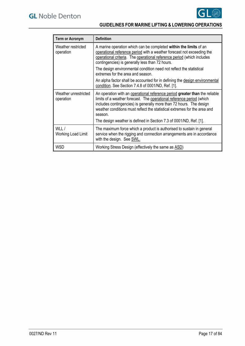
Term or Acronym Definition
Weather restricted operation
A marine operation which can be completed within the limits of an operational reference period with a weather forecast not exceeding the operational criteria. The operational reference period (which includes contingencies) is generally less than 72 hours.
The design environmental condition need not reflect the statistical extremes for the area and season.
An alpha factor shall be accounted for in defining the design environmental condition. See Section 7.4.8 of 0001/ND, Ref. [1].
Weather unrestricted operation
An operation with an operational reference period greater than the reliable limits of a weather forecast. The operational reference period (which includes contingencies) is generally more than 72 hours. The design weather conditions must reflect the statistical extremes for the area and season.
The design weather is defined in Section 7.3 of 0001/ND, Ref. [1].
WLL / Working Load Limit
The maximum force which a product is authorised to sustain in general service when the rigging and connection arrangements are in accordance with the design. See SWL.
WSD Working Stress Design (effectively the same as ASD)
GUIDELINES FOR MARINE LIFTING & LOWERING OPERATIONS
0027/ND Rev 11 Page 18 of 84
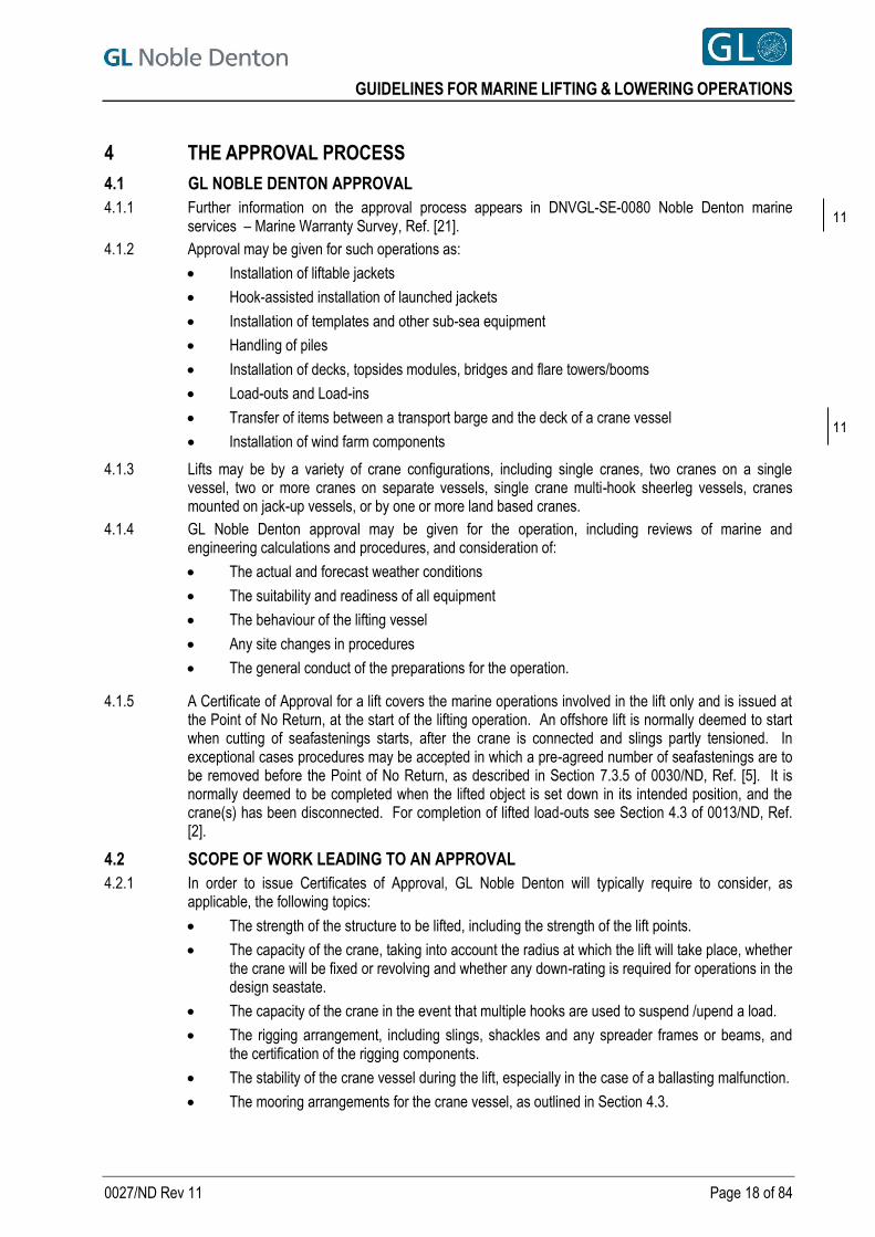
4 THE APPROVAL PROCESS
4.1 GL NOBLE DENTON APPROVAL
4.1.1 Further information on the approval process appears in DNVGL-SE-0080 Noble Denton marine services – Marine Warranty Survey, Ref. [21].
4.1.2 Approval may be given for such operations as:
Installation of liftable jackets
Hook-assisted installation of launched jackets
Installation of templates and other sub-sea equipment
Handling of piles
Installation of decks, topsides modules, bridges and flare towers/booms
Load-outs and Load-ins
Transfer of items between a transport barge and the deck of a crane vessel
Installation of wind farm components
4.1.3 Lifts may be by a variety of crane configurations, including single cranes, two cranes on a single vessel, two or more cranes on separate vessels, single crane multi-hook sheerleg vessels, cranes mounted on jack-up vessels, or by one or more land based cranes.
4.1.4 GL Noble Denton approval may be given for the operation, including reviews of marine and engineering calculations and procedures, and consideration of:
The actual and forecast weather conditions
The suitability and readiness of all equipment
The behaviour of the lifting vessel
Any site changes in procedures
The general conduct of the preparations for the operation.
4.1.5 A Certificate of Approval for a lift covers the marine operations involved in the lift only and is issued at the Point of No Return, at the start of the lifting operation. An offshore lift is normally deemed to start when cutting of seafastenings starts, after the crane is connected and slings partly tensioned. In exceptional cases procedures may be accepted in which a pre-agreed number of seafastenings are to be removed before the Point of No Return, as described in Section 7.3.5 of 0030/ND, Ref. [5]. It is normally deemed to be completed when the lifted object is set down in its intended position, and the crane(s) has been disconnected. For completion of lifted load-outs see Section 4.3 of 0013/ND, Ref. [2].
4.2 SCOPE OF WORK LEADING TO AN APPROVAL
4.2.1 In order to issue Certificates of Approval, GL Noble Denton will typically require to consider, as applicable, the following topics:
The strength of the structure to be lifted, including the strength of the lift points.
The capacity of the crane, taking into account the radius at which the lift will take place, whether the crane will be fixed or revolving and whether any down-rating is required for operations in the design seastate.
The capacity of the crane in the event that multiple hooks are used to suspend /upend a load.
The rigging arrangement, including slings, shackles and any spreader frames or beams, and the certification of the rigging components.
The stability of the crane vessel during the lift, especially in the case of a ballasting malfunction.
The mooring arrangements for the crane vessel, as outlined in Section 4.3.
11
11

GUIDELINES FOR MARINE LIFTING & LOWERING OPERATIONS
0027/ND Rev 11 Page 19 of 84
DP audit documentation and FMEA analysis and DP procedures detailing positioning systems (see Section 13.8 of 0001/ND, Ref. [1].)
The limiting design weather conditions proposed and the anticipated behaviour of the crane vessel and the transport barge or vessel carrying the structure in those conditions.
The arrangements for handling and mooring the transport barge or vessel alongside the crane vessel.
The arrangements for cutting seafastenings before lifting.
The management structure for the operations and Management of Change procedures.
ROV performance documentation.
Risk assessments, HAZOP / HAZID studies involving key personnel of all relevant parties.
Simultaneous Marine Operations (SIMOPS).
The completion of the preparations at the installation location to receive the structure.
4.2.2 The information required in order to issue a Certificate of Approval is listed in Appendix A.
4.2.3 Technical studies leading to the issue of a Certificate of Approval may consist of:
a. Reviews of specifications, procedures and calculations submitted by the client or his contractors, or
b. Independent analyses carried out by GL Noble Denton to verify the feasibility of the proposals, or
c. A combination of third party reviews and independent analyses.
4.3 APPROVAL OF MOORINGS
4.3.1 A lift may normally be considered a weather- restricted operation. Limiting weather conditions for the lift operation shall be defined, taking into account:
the weather forecast reliability and frequency for the area
the duration of the operation, including a suitable contingency period
the exposure of the site
the time required for any operations before or after the lift operation, including crane vessel and transport barge movements.
currents on the lifting vessel/transport barge during the lift.
currents on the lifted structure during lowering through the water column.
4.3.2 An approval of a lift will normally include the approval of the crane vessel and transport barge moorings in the limiting design weather conditions specified for the lifting operation. When operating alongside an offshore installation, procedures should be submitted which show that the crane vessel and transport barge can and will be removed to a safe distance when the weather conditions exceed a specified level. An approval of a lift does not include approval of the vessel moorings in extreme weather conditions.
4.3.3 Similarly, an approval of a lifted load-out will include the approval of the crane vessel and transport barge moorings at the load-out quay in the limiting design weather conditions specified for load-out. It does not necessarily include approval of the crane vessel and/or transport barge moorings in extreme weather conditions. Note that for approval of load-outs, reference should also be made to 0013/ND - Guidelines for Load-Outs, Ref. [2].
4.3.4 Additionally, and if specifically requested, GL Noble Denton will study and issue an approval of the moorings of the crane vessel or the transport barge, for a more extended period.
4.4 LIMITATION OF APPROVAL
4.4.1 See DNVGL-SE-0080 Noble Denton marine services – Marine Warranty Survey, Ref. [21].
11

GUIDELINES FOR MARINE LIFTING & LOWERING OPERATIONS
0027/ND Rev 11 Page 20 of 84
4.5 SURVEYS
4.5.1 Where GL Noble Denton approval for lifting operations is required, the surveys shown in Table 4-1 will usually be needed:
Table 4-1 Typically Required Surveys
Survey Time Place
Sighting of inspection / test certificates or release notes for spreader bars, lift points and attachments
Before departure of structure from shore and before offshore lift (if after a lifted load-out)
GL Noble Denton / client's office and / or fabrication yard Sighting of certificates and inspection reports for
slings and shackles. Inspection of rigging and laydown and rigging tie-down / seafastening
Witness or review relevant reports for testing of any items required for installation activities (e.g. rotational tests on spreader bars for jacket upending, testing of diaphragms required for water tight compartments, etc.)
Fabrication yard or subcontractor’s facility
Inspection of securing of loose items inside module
Inspection of Survey & Positioning equipment on structure and on seabed
Before departure and start of marine operations
Fabrication yard and lift site
Suitability survey of crane / installation vessel, if required
Before start of marine operations
As available
Crane / installation vessel mooring activities
At lift site Crane / installation vessel in field DP trials
Inspection of preparations for lift and issue of Certificate of Approval
Immediately before cutting seafastening
11
GUIDELINES FOR MARINE LIFTING & LOWERING OPERATIONS
0027/ND Rev 11 Page 21 of 84
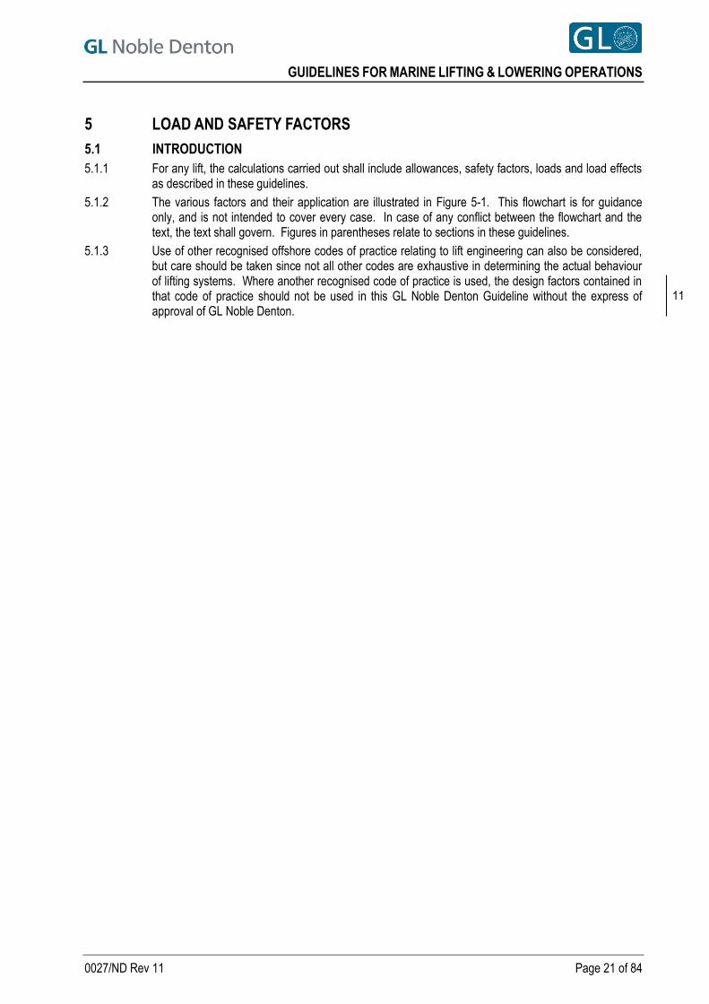
5 LOAD AND SAFETY FACTORS
5.1 INTRODUCTION
5.1.1 For any lift, the calculations carried out shall include allowances, safety factors, loads and load effects as described in these guidelines.
5.1.2 The various factors and their application are illustrated in Figure 5-1. This flowchart is for guidance only, and is not intended to cover every case. In case of any conflict between the flowchart and the text, the text shall govern. Figures in parentheses relate to sections in these guidelines.
5.1.3 Use of other recognised offshore codes of practice relating to lift engineering can also be considered, but care should be taken since not all other codes are exhaustive in determining the actual behaviour of lifting systems. Where another recognised code of practice is used, the design factors contained in that code of practice should not be used in this GL Noble Denton Guideline without the express of approval of GL Noble Denton.
11

GUIDELINES FOR MARINE LIFTING & LOWERING OPERATIONS
0027/ND Rev 11 Page 22 of 84
Figure 5-1 Lift Calculation Flowchart
(Numbers in [ ] indicate the referenced section of this document)
Apply weight contingency factor [5.2] Calculate lift point & sling loads [6.3] & [6.4]
DEFINE SLING / GROMMET MBL & SHACKLE WLL REQUIRED [7] & [8.2]
DETERMINE LATERAL LIFT POINT LOAD [12.3]
IDENTIFY / REPORT RIGGING UTILISATION FACTORS & RIGGING
GEOMETRY
CALCULATE STATIC and DYNAMIC HOOK LOADS [10.3]
LIFT POINT & SPREADER BAR OK RIGGING OK CRANE OK
VERIFY GLOBAL STRUCTURAL DESIGN OF
LIFTED STRUCTURE [11]
Check hook load with crane capacity (static & dynamic) at the given
radius [10.3]
OBTAIN
Crane data
Lift arrangement
Number of cranes & hooks
Structure Net or weighed weight
Lift point geometry
CoG location & envelope
In air or submerged lift
Barge ballast data
APPLY CONSEQUENCE FACTORS FOR SPREADER BAR & LIFT POINT DESIGN
CHECKS [11.4]
DETERMINE LIFT FACTORS
Minimum tilt angle [5.3]
Tilt effect (2-hook lift) [5.4]
Yaw factor (2-hook lift) [5.4]
DAF [5.5]
SKL factor [5.6]
Minimum sling angle [6.4]
VERIFY LIFT POINT AND SPREADER BAR DESIGN
[11] & [12]
REVIEW
Installation clearances above & below waterline [16]
Bumper & guide design &
geometry [17]
GUIDELINES FOR MARINE LIFTING & LOWERING OPERATIONS
0027/ND Rev 11 Page 23 of 84
5.2 WEIGHT CONTINGENCY & CENTRE OF GRAVITY FACTORS
5.2.1 Weight Contingency and Centre of Gravity control requirements are given in Section 8 of 0001/ND, Ref. [1], which in turn references ISO Standard 19901-5, Ref. [8].
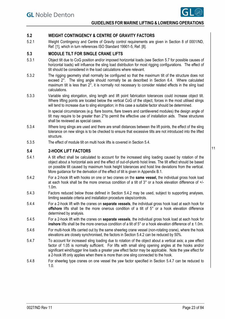
5.3 MODULE TILT FOR SINGLE CRANE LIFTS
5.3.1 Object tilt due to CoG position and/or imposed horizontal loads (see Section 5.7 for possible causes of horizontal loads) will influence the sling load distribution for most rigging configurations. The effect of tilt should be considered in the load calculations where relevant.
5.3.2 The rigging geometry shall normally be configured so that the maximum tilt of the structure does not exceed 2°. The sling angle should normally be as described in Section 6.4. Where calculated maximum tilt is less than 2°, it is normally not necessary to consider related effects in the sling load calculations.
5.3.3 Variable sling elongation, sling length and lift point fabrication tolerances could increase object tilt. Where lifting points are located below the vertical CoG of the object, forces in the most utilised slings will tend to increase due to sling elongation; in this case a suitable factor should be determined.
In special circumstances (e.g. flare booms, flare towers and cantilevered modules) the design angle of tilt may require to be greater than 2°to permit the effective use of installation aids. These structures shall be reviewed as special cases.
5.3.4 Where long slings are used and there are small distances between the lift points, the effect of the sling tolerance on new slings is to be checked to ensure that excessive tilts are not introduced into the lifted structure.
5.3.5 The effect of module tilt on multi hook lifts is covered in Section 5.4.
5.4 2-HOOK LIFT FACTORS
5.4.1 A tilt effect shall be calculated to account for the increased sling loading caused by rotation of the object about a horizontal axis and the effect of out-of-plumb hoist lines. The tilt effect should be based on possible tilt caused by maximum hook height tolerances and hoist line deviations from the vertical. More guidance for the derivation of the effect of tilt is given in Appendix B.1.
5.4.2 For a 2-hook lift with hooks on one or two cranes on the same vessel, the individual gross hook load at each hook shall be the more onerous condition of a tilt of 3° or a hook elevation difference of +/-1.0m.
5.4.3 Factors reduced below those defined in Section 5.4.2 may be used, subject to supporting analyses, limiting seastate criteria and installation procedure steps/controls.
5.4.4 For a 2-hook lift with the cranes on separate vessels, the individual gross hook load at each hook for offshore lifts shall be the more onerous condition of a tilt of 5° or a hook elevation difference determined by analysis.
5.4.5 For a 2-hook lift with the cranes on separate vessels, the individual gross hook load at each hook for inshore lifts shall be the more onerous condition of a tilt of 5° or a hook elevation difference of ± 1.0m.
5.4.6 For multi-hook lifts carried out by the same sheerleg crane vessel (non-rotating crane), where the hook elevations are closely synchronised, the factors in Section 5.4.2 can be reduced by 50%.
5.4.7 To account for increased sling loading due to rotation of the object about a vertical axis; a yaw effect factor of 1.05 is normally sufficient. For lifts with small sling opening angles at the hooks and/or significant wind/tugger line loads a greater yaw effect factor may be applicable. Note the yaw effect for a 2-hook lift only applies when there is more than one sling connected to the hook.
5.4.8 For sheerleg type cranes on one vessel the yaw factor specified in Section 5.4.7 can be reduced to 1.0.
11

GUIDELINES FOR MARINE LIFTING & LOWERING OPERATIONS
0027/ND Rev 11 Page 24 of 84
5.5 DYNAMIC AMPLIFICATION FACTORS
5.5.1 Unless operation-specific calculations show otherwise, for lifts by a single crane in air, the DAF shall be derived from Table 5-1.
Table 5-1 Dynamic Amplification Factors (DAF) in Air
Gross weight, W (tonnes)
DAF
Onshore 2) Inshore 3), 5) Offshore 4), 5)
31) < W ≤ 100 1.10 1.07 + 0.05√100/𝑆𝐻𝐿 1 + 0.25√100/𝑆𝐻𝐿
100 < W ≤ 300 1.05 1.12 1.25
300 < W ≤ 1000 1.05 1.10 1.20
1000 < W ≤ 2500 1.03 1.08 1.15
W > 2500 1.03 1.05 1.10
Note:
1) For lifted items weighing less than 3 tonnes, it is recommended to assume the item weighs 3 tonnes and this is used throughout the calculations for the rigging design.
2) For onshore crawler cranes travelling with load, possible dynamic effects should be evaluated thoroughly. Crane speeds and surface conditions should be considered. If no documentation is presented, the factors for “inshore lifts” should be used.
3) Inshore is applicable to a lift with a crane vessel to/from a vessel in sheltered waters and is also applicable to lifting from the deck of a crane vessel onto a fixed platform at an offshore location.
4) Offshore is applicable to a lift by a crane vessel from another vessel to a fixed platform.
5) SHL refers to the Static Hook Load (see Section 6.2.2 and Section 6.2.3).
5.5.2 The DAF as indicated in Table 5-1 above shall also apply to the following in air lift combinations of vessels, cranes and locations:
For lifts by 2 cranes on the same vessel
For onshore lifts by 2 or more cranes
For lifts by 2 or more hooks on the same crane boom (but see Section 5.5.6 for offshore lifts)
For inshore lifts, in totally sheltered waters, by 2 or more vessels.
5.5.3 The DAF as indicated in Table 5-1 above shall also apply to the following lifts by cranes on jacked-up crane vessels:
onto or from floating vessels use the “Offshore” or “Inshore” column, as appropriate
onto fixed structures from its own deck, use the “Inshore” column. If the crane is not moving horizontally on tracks or wheels, and horizontal motions of the load can be minimised by suitably located crane tuggers, a DAF of 1.0 may be used provided the lifting and lowering operations are carried out to avoid any dynamic snatching of the load.
5.5.4 For onshore lifts, where there is no crane movement other than lifting or lowering, a DAF of 1.0 may be used provided the lifting and lowering operations are carried to avoid any dynamic snatching of the load.
5.5.5 For offshore lifts by 2 or more vessels, the DAF shall be found by dynamic analysis.
5.5.6 For offshore lifts by 2 or more hooks on the same crane boom, total load on the crane boom structure shall be documented, based on Table 5-1 DAFs multiplied by 1.10 unless certified crane curves for this specific application can be provided.
11
GUIDELINES FOR MARINE LIFTING & LOWERING OPERATIONS
0027/ND Rev 11 Page 25 of 84
5.5.7 If any part of the lifting operation includes lifting or lowering a structure or spool through water, analyses shall be submitted, which either:
Show how the total in-water lifting loads are derived, taking into account weight, buoyancy, entrained mass, boom-tip velocities and accelerations, inertia and drag forces, or;
Calculate the dynamic sling and hook loads to document that slack slings do not occur and provide limiting seastate data for the offshore operation.
Calculate the local and global stresses in the spool;
Calculate slamming loads on the structure being lifted.
The dynamic analysis results for a submerged or partially submerged lift may restrict the operability of an operation that is subject to the issue of a Certificate of Approval, depending on the DAF used for rigging and structure design.
5.5.8 As an alternative to the DAFs in Table 5-1, the DAF may be derived from a suitable calculation or model test. Where the lift is from or onto a barge or vessel alongside the crane vessel, then the barge or vessel motions must be taken into account as well as the crane boom-tip motions.
5.6 SKEW LOAD FACTOR (SKL)
5.6.1 Skew loads are additional loading caused by rigging fabrication tolerances, fabrication tolerances of the lifted structure and other uncertainties with respect to asymmetry and associated force distribution in the rigging arrangement. The skew load factor (SKL) is a load distribution factor based on:
rigging length manufacturing tolerances,
sling / grommet measurement tolerances over measuring pins,
rigging arrangement and geometry,
fabrication tolerances for lift points,
sling / grommet elongation,
crane geometry,
and should be considered for any rigging arrangement and structure (see Sections 11.2 and 11.3) that is not 100% determinate. A significantly higher SKL factor may be required for new slings used together with existing slings as one sling may exhibit more elongation than the others.
5.6.2 For rigging configurations involving slings from more than 4 lift points connected to a single hook, skew load effects shall be calculated on a case by case basis.
5.6.3 When determining the length of a sling or grommet, the effect of the pin used in the measurement of the sling / grommet should be considered as the connection points for the sling / grommet may have a different diameter to the pin causing the in-use length to be different to the measured length.
5.6.4 When determining the rigging lengths and angles, the effect of the hook geometry and hook prong diameter should be considered as these will affect the working points for the rigging when determining lengths and the hook prong diameter may affect the measured length of the sling / grommet (see 5.6.3).
5.6.5 For determinate lifts (with or without a single spreader bar) the SKL may be taken to be 1.0, provided it can be demonstrated that sling length errors do not significantly affect the load attitude or lift system geometry. The permitted length tolerance on the slings / grommets for the use of the SKL of 1.0 is
such that the lengths shall be within ±0.5% of their nominal length. Where the tolerance is outside
this, the effect of the sling length should be considered on the load distribution to the lift points incorporating any tilt effects caused by the sling length tolerances.
5.6.6 For a lift system using matched pairs of slings and incorporating 2 or more spreader bars, a SKL of 1.10 is applicable provided the following conditions are achieved:
a) An approximately symmetric rigging geometry is utilised.
b) The sling lengths are within 0.5% of their nominal length. c) The calculated axial load in the spreader bar is at least 15% of the sling load
11

GUIDELINES FOR MARINE LIFTING & LOWERING OPERATIONS
0027/ND Rev 11 Page 26 of 84
If the stated conditions are not met, the SKL should normally be found by calculation. However, generally if the length tolerance is stricter than stated, the minimum axial load requirement in the spreader bars could be relaxed.
5.6.7 For lifts where more than two hooks are used and each hook is connected to a single spreader bar, a SKL of 1.1 should be used. A reduced value may be justified provided the hook elevations can be shown to be individually controlled and subject to evaluation of sling length tolerances, the rigging arrangement and crane operating procedures.
5.6.8 For indeterminate 4-sling lifts using matched pairs of cable laid slings or grommets, a Skew Load Factor (SKL) of 1.25 shall be applied to each diagonally opposite pair of lift points in turn provided the following are applicable:
For Slings:
The slings are fabricated with a length tolerance of ±1.5d and the difference between a matched pair of slings shall not be more than 0.5d where d is the sling diameter.
The slings are of a standard construction and meet the criteria of 160xW/d2 <1.0 where W is the weight in kilograms (kg) per metre (m) of the sling and d is the sling diameter.
The slings are installed so that the longer slings of each matched pair are not on the same diagonal.
Sling utilisation when checking with the termination factor (see Sections 7.3.1 and 7.7.1) and a skew factor of 1.25 should be more than 0.6.
For Grommets:
The grommets are fabricated with a circumferential length tolerance of ±3.0d and the difference between a matched pair of grommets shall not be more than 1.0d where d is the grommet diameter.
The grommets are of a standard construction and meet the criteria of 160xW/d2 <1.0 where W is the weight in kilograms (kg) per metre (m) of the each leg of the grommet and d is the grommet diameter.
The grommets are installed so that the longer grommets of each matched pair are not on the same diagonal.
Grommet utilisation when checking with a termination factor of 1.0 (see Sections 7.3.1 and 7.6.1) and a skew factor of 1.25 should be more than 0.6.
Note: where sling or grommet utilisations are less than 0.6, whilst a higher skew factor will not overload the slings/grommets, the load on the lift point may increase and the effect of this shall be included in the design for the lift points.
5.6.9 In lieu of the skew factors used in Section 5.6.8, the actual skew factor may be determined using a more detailed analysis allowing for actual rigging properties, extreme tolerances for new build rigging, and hook rotation. Where possible, the analysis should include the lifted structure so that the effect of the structure’s stiffness can be considered or where this is not carried out, the structure can be considered infinitely stiff and thus offers no reduction to the skew value determined.
5.6.10 For indeterminate 4-sling lifts using four cable laid slings of un-equal length, the skew load shall be calculated using an elastic modulus, E, of 25,000 N/mm2 with the sling area used based on a value of 0.785 x d2, where d is the sling diameter in mm, and the sling lengths based on the most onerous fabrication tolerances.
5.6.11 For indeterminate 4-grommet lift using four cable laid grommets of un-equal length, the skew load shall be calculated using an elastic modulus, E, of 25,000 N/mm2 with the grommet area used based on a value of 1.57 x d2, where d is the diameter in mm of one leg of the grommet, and the grommet lengths based on the most onerous fabrication tolerances.
11
GUIDELINES FOR MARINE LIFTING & LOWERING OPERATIONS
0027/ND Rev 11 Page 27 of 84
5.6.12 For indeterminate 4-sling lifts using matched pairs of single laid slings, a Skew Load Factor (SKL) of 1.25 shall be applied to each diagonally opposite pair of lift points in turn provided the following are applicable:
The slings are fabricated with a length tolerance of ±2.0d and the difference between a matched pair of slings shall not be more than 1.0d where d is the sling diameter;
The slings are of a standard construction and meet the criteria of 230xW/d2 <1.0 where W is the weight in kilograms (kg) per metre (m) of the sling and d is the sling diameter.
The slings are installed so that the longer slings of each matched pair are not on the same diagonal.
Sling utilisation when checking with the splice efficiency factor (see Sections 7.3.1and 7.7.1) and a skew factor of 1.25 should be more than 0.6.
Note, where utilisations are less than 0.6, whilst a higher skew factor will not overload the slings, the load on the lift point may increase and the effect of this shall be included in the design for the lift points.
5.6.13 For indeterminate 4-sling lifts using four single laid slings of un-equal length, the skew load shall be calculated using an elastic modulus, E, of 80,000 N/mm2 with the sling area used based on a value of 0.785 x d2, where d is the sling diameter in mm, and the sling lengths based on the most onerous fabrication tolerances.
5.7 ADDITIONAL FACTORS
5.7.1 When appropriate, allowances for special loads should be made in the derivation of loads on the lifted structure, lift points and rigging system. These special loads may include tugger line loads, guide loads, wind loads, hydrostatic and hydrodynamic loads.
5.8 2-PART SLING FACTOR
5.8.1 Where a 2-part sling or grommet passes over, round or through a shackle, trunnion, padear or crane hook, other than at a termination, the total sling force shall be distributed into each part in the ratio 45:55 to account for frictional losses over the bend.
5.8.2 Where upending a structure requires the sling or grommet to slide over a trunnion or crane hook utilising a 2-part sling or grommet, other than at a termination, the total sling force shall be distributed into each part in the ratio 32.5:67.5 to account for frictional effects as the wire slides over the bend. For this condition, the ratio may be reduced if the lifting contractor can demonstrate through documented evidence or testing that a lesser value can be adopted.
5.8.3 Where a 2-part sling or grommet passes over a rotating greased sheave on a trunnion the total sling force shall be distributed into each part in the ratio 49:51 to account for the frictional losses over the rotating sheave on the trunnion.
5.8.4 Where slings or grommets are used in any more that a 2-part configuration, calculations shall be submitted for review, and will require special consideration by GL Noble Denton. The calculations submitted shall allow for the frictional losses contained in 5.8.1 or 5.8.2 (e.g. the 45:55 effect in a double doubled sling would be 0.55 x 0.55 on the design load in each leg of the sling or grommet).
5.8.5 If a doubled sling consists of two parallel slings, the load distribution should be calculated considering the maximum sling length difference between the two slings and the maximum sling modulus of elasticity (E).
5.8.6 When using fibre slings or grommets (i.e. Dyneema, HMPE, Round slings or webbing slings) in a doubled configuration the 2-part sling factor referenced in Section 5.8.1 shall be used for guidance, but the specific recommendations of the sling supplier should govern, based on the planned mode of use and the specifics of the sling type.
5.9 LIFT STABILITY
For lifting operations carried out where the Centre of Gravity of the lifted object is above the lift points, care should be taken to ensure that the stability of the lifting arrangement is considered in the design. This is of particular concern where spreader bars or spreader frames are used as part of the lift system. Stability should be demonstrated for these conditions allowing for both vertical and horizontal offsets in the position of the Centre of Gravity.
11
11
11

GUIDELINES FOR MARINE LIFTING & LOWERING OPERATIONS
0027/ND Rev 11 Page 28 of 84
6 DERIVATION OF HOOK, LIFT POINT, AND RIGGING LOADS
6.1 INTRODUCTION
6.1.1 The following sections determine the loads to be used for confirming the suitability of the cranes and for the design of rigging components using the parameters laid down in Section 5.
6.2 HOOK LOADS
6.2.1 The total loading on the crane hook(s) should be based on the lifted item Design Weight, where the Design Weight is as follows:
Design Weight = Net Weight x Weight Contingency Factor (see Sections 8.3.1 to 8.3.3 of 0001/ND, Ref. [1]) or
Design Weight = Weighed Weight x Weight Contingency Factor (see Sections 8.3.8 and 8.3.9 of 0001/ND, Ref. [1]), or
Design Weight = NTE Weight x Weight Contingency Factor (see Section 8.1.1, 8.1.2, 8.3.5 and 8.3.6 of 0001/ND, Ref. [1]).
Note: for piles, the Design Weight shall be calculated based on Section 8.3.4 of 0001/ND, Ref. [1].
6.2.2 For single crane lifts, the hook loads are as follows:
Static Hook load = (Design Weight) + (Rigging Weight) + (Additional Loads)
Dynamic Hook load = Static Hook load x DAF
For Additional Loads, clarification is given in Section 5.7.1.
6.2.3 For twin hook lifts whether cranes are on the same vessel, or multiple vessels, or the structure is suspended from two hooks on the same crane on the same vessel, the load to each hook shall be based on the Design Weight (see Section 6.2.1) proportioned by the geometric distance of the centre of gravity from each of the hooks allowing for the effect of the module tilt / hook elevation tolerances given in Section 5.4. Where a CoG envelope is used (see Section 8.3 of 0001/ND, Ref. [1]), the hook loads should be calculated for a CoG position at the extremes of the CoG envelope. Where no CoG envelope is used, the hook loads are to be increased by the factor given in Section 8.3.3 of 0001/ND, Ref. [1].
The final static hook load is then determined by the additional rigging weight connected to the hook and the addition of additional loads in accordance with Section 5.7.1.
The dynamic hook load is then determined in a similar way to the formula for the dynamic hook load in Section 6.2.2.
6.2.4 Rigging weight includes all items between the lift points and the crane hook, including slings, shackles, lifting tools and spreader bars or frames as appropriate.
6.2.5 For lifting operations involving pivoting and/or upending manoeuvres (e.g. roll-up operation, jacket upending operation etc.), an adequate number of steps shall be analysed to ensure that the critical load cases for the derivation of hook loads are identified. Where it is noted that there is the possibility for higher loads to occur between the angles selected, then intermediate steps between the selected angles should be considered.
6.2.6 The calculated hook loads are to be checked against the crane capacities - see Section 10.3.
6.2.7 Beware of different approaches to crane capacity for land-based cranes, which typically specify the maximum load below the boom-head pulleys, and offshore cranes which typically specify the maximum hook load for a given radius. This is due to land-based cranes being more often re-reeved with different blocks to optimise crane capacity but requires the deduction of hook block and rope weight to find the hook load. For further details, see Section 13.7.
11

GUIDELINES FOR MARINE LIFTING & LOWERING OPERATIONS
0027/ND Rev 11 Page 29 of 84
6.3 LIFT POINT LOADS
6.3.1 The basic vertical lift point load is the load at a lift point, taking into account the Design Weight as given in Section 6.2.1 proportioned by the geometric distance of the centre of gravity, accounting for
Where a CoG envelope is used (see Section 8.4.1 of 0001/ND, Ref. [1]), the lift point loads should be calculated for a CoG position at the extremes of the CoG envelope. For twin hook lifts, the effect of tilt / hook elevation tolerances given in Section 5.4 should be accounted for.
Where no CoG envelope is used, the lift point loads are to be increased by the factor given in Section 8.4.3 of 0001/ND, Ref. [1]. For twin hook lifts, the effect of tilt / hook elevation tolerances given in Section 5.4 should be accounted for.
The basic lift point load is further increased by the following factors (as listed in Figure 5-1) as appropriate for the lifting arrangement under consideration:
Dynamic Amplification Factor (see Section 5.5)
Yaw Factor (see Section 5.4.7) for twin hook lifts
Skew Load Factor (see Section 5.6)
Additional Factors (see Section 5.7.1)
6.3.2 If the lift points are at different elevations as shown in Figure 6-1 then sling forces shall be resolved at the sling intersection point, IP, which will be above the hook (if connected directly to the hook) or, if connected to a shackle /sling system suspended from the hook, the IP will be above the connection point on the shackle. The design sling loads should consider a CoG envelope and the loads in the slings determined by positioning the extremes of the CoG envelope under the IP and the sling loads recalculated using the new sling angles α and β.
Figure 6-1 Resolving Sling Loading
6.3.3 For lift points where double trunnions or double padears are connected to a structure and are considered as a single lift point when determining loads, such as a double trunnion connected to the apex chord of a flare, the following effects of tilt and rotation shall be considered in the design of both structure and slings or grommets.
a) Tilt can cause uneven loading unless there is means to ensure that the load on the two sides of the trunnion or padear is equalised.
b) Tilt can also cause the rigging to shift along the bearing surface of the trunnion or padear such that increased moment is introduced into the trunnion or padear.
c) As a result of friction, rotation of the sling eye or grommet round the padear or trunnion can result in significant torque on the padear or trunnion (and unequal loading in the legs of a grommet or doubled sling).
The use of a “matched pair” of slings or grommets connected to a double trunnion or double padear should be avoided as they are rarely adequately matched. If they are used, then the slings or grommets must have identical lengths when measured under the same tension. Where there are differences in the lengths, the effect of unequal lengths shall be considered in the design (see Section 5.8.5 for further details).
6.4 SLING LOADS
6.4.1 The sling load is the vertical lift point load resolved by the sling angle to determine the direct (axial) load in the sling and lift point using the minimum possible sling angle.
6.4.2 The sling angle should not normally be less than 45º to the horizontal although for lifts that are installed at an angle this may not be the case, e.g. flare booms installed by a single crane, the upper rigging may be less than 45º.
Sling IP
`
α β
CoG
11
11
11
GUIDELINES FOR MARINE LIFTING & LOWERING OPERATIONS
0027/ND Rev 11 Page 30 of 84
6.4.3 Where long slings are used and there are small distances between the lift points, the effect of the sling tolerance on new build slings is to be checked to ensure that excessive tilts are not introduced into the lifted structure causing an increase in the lift point loads.
6.4.4 For lift point design, the rigging weight shall not form part of the lift point load.
6.4.5 For derivation of sling loads where the lift points are at different elevations, refer to Section 6.3.2.
11
GUIDELINES FOR MARINE LIFTING & LOWERING OPERATIONS
0027/ND Rev 11 Page 31 of 84
7 SLING AND GROMMET DESIGN
7.1 INTRODUCTION
7.1.1 The following section covers the design of slings and grommets using the loads derived in section 6. The various factors and their application are illustrated in Figure 5.1 which is for guidance only, and is not intended to cover every case. In case of any conflict between the flowchart and the text, the text shall govern.
7.1.2 The principles for design in this document are based on engineered and planned lifts using inspected and certified rigging. Rigging generally consists of purpose built slings or well-maintained stock slings. European code EN 13414-3, Ref [17], covers all aspects of lifting with grommets including engineered lifts and general site activities. This is recognised in the introduction to the EN code where justification for lower factors of safety on larger diameters is clarified in that the higher diameters are used for engineered lifts and not general service lifts. For the smaller diameters it is recognised that the use of these are likely to be based on basic weight and CoG parameters with the lift not fully engineered and planned. Hence the EN code uses higher safety factors for this size of rigging.
7.2 SLING OR GROMMET DESIGN
7.2.1 The calculated maximum dynamic sling load should comply with the following requirements:
FSD < MBL sf
Where: FSD = Sling design load (see Section 6.4) MBL = Minimum Breaking Load of sling (see Section 14.2 for steel slings or 14.3 for fibre slings) sf = Nominal safety factor for sling (see section 7.3)
7.2.2 In the absence of documentary evidence, it is assumed that the MBL provided for slings and grommets is specified without possible reductions due to end terminations (see Section 7.7).
7.2.3 When selecting a grommet, attention should be paid to the MBL quoted by the supplier as this is not normally that for a single leg of the grommet but is the total for both legs of the grommet without bending reductions or a reduction to account for unequal loading in each leg of the grommet (see Section 5.8). Consequently, grommets require special consideration to ensure that the MBL has been correctly taken into account. The load in a grommet shall be distributed into each part in the ratio as indicated by Section 5.8. Hence, when checking a grommet, the design load in one part of the grommet is to be checked against the MBL of the grommet part, i.e.:
when a grommet is used in a straight line pull, 50% of the quoted MBL will be used in the formula in Section 7.2.1,
when a grommet is used in a doubled configuration, 25% of the quoted MBL will be used in the formula in Section 7.2.1
7.3 SLING OR GROMMET NOMINAL SAFETY FACTORS FOR DESIGN
7.3.1 The nominal safety factor for slings and grommets, sf, should be taken as the greatest of the following
products of partial factors:
sf = f c r w mtw
sf = 2.3 r w tw
Details of the partial safety factors are given in Sections 7.4 to 7.10.4.
7.3.2 For fibre slings and grommets the minimum safety factor shall be not less than that recommended by the manufacturer or 2.3 if greater.
11

GUIDELINES FOR MARINE LIFTING & LOWERING OPERATIONS
0027/ND Rev 11 Page 32 of 84
7.4 LOAD FACTOR f
7.4.1 The load factor, f, should normally be taken as 1.3. A reduced load factor may be considered in some
cases which are given in 7.4.2 and 7.4.3. If alternative methods are used and a reduced load factor is adopted, this must be agreed with GL Noble Denton.
7.4.2 A reduced load factor, f, of 1.2 may be considered applicable provided the all skew load effects have
been accurately calculated and the dynamic load component is less than the permanent (dead) load component. The factor of 1.2 would also apply on any variable load caused by winches e.g. tugger lines, impact loads caused by bumpers/guides etc.
7.4.3 Where a detailed computer analysis of the lift is carried out the load factor, f, may be taken as the
greater of:
1.3 – (0.6 x EL / TL);
1.0 + (0.3 x EL / TL).
Where:
EL = Load in rigging caused by the environmental loading from wind, waves, current etc.
TL = Total load in rigging from permanent (dead) load, variable load (winch loads, impact loads etc.) and environmental loads (wind, waves, current etc.).
Note, this method is only applicable where a detailed analysis has been undertaken where the structure, rigging system and crane vessel are modelled and the environmental loading is considered in the load cases but it is not applicable if the environmental loading is based on the DAF value given in Table 5-1.
For onshore lifts where the structure remains in contact with some fabrication supports, e.g. for a roll-up operation, deformation due to support settlement may need to be considered. See Sections 13.3 to 13.5 for further details.
7.5 CONSEQUENCE FACTOR c
7.5.1 The consequence factor, c, should normally be taken as 1.3. A reduced consequence factor may be
considered in some cases which are given in 7.5.2 and 7.5.3. If an alternative consequence factor is used, this must be agreed with GL Noble Denton.
7.5.2 If a single sling failure does not result in the total loss of the lifted structure, or the consequences of sling failure may be regarded as negligible, a lower consequences factor may be applied subject to agreement with GL Noble Denton but see Section 18.1.8.
7.5.3 A lower consequence factor could be applicable if the consequence of failure is considered tolerable by all involved parties e.g. if the rigging is used for pulling/hold-back only and the consequences of rigging failure may be regarded as small, then a lower consequence factor may be applied subject to agreement with GL Noble Denton.
7.6 SLING OR GROMMET REDUCTION FACTOR r
7.6.1 The reduction factor, r, due to end termination or bending is to be taken as the greatest of s
(termination factor, see Section 7.7) and b (bending factor, see Section 7.8).
7.7 TERMINATION FACTOR s
7.7.1 The termination factor, s, for the end termination of the slings and wire ropes shall be documented.
The following minimum factors should normally be adopted and further details are given in EN 13411 (although nominally limited to wire ropes up to 60mm in diameter, the factors from EN 13411 are used here for larger diameters), Refs [14] to [16].
11

GUIDELINES FOR MARINE LIFTING & LOWERING OPERATIONS
0027/ND Rev 11 Page 33 of 84
For wire ropes:
Hand splices on wire ropes: 1.25 (refer to EN 13411-2 for requirements)
Steel ferrules (mechanical termination): 1.12 (refer to EN 13411-3 for requirements)
Resin sockets: 1.00 (refer to EN 13411-4 for requirements)
Swage fittings, e.g. “Superloop or Flemish Eye”: 1.00 (refer to EN 13411-4 for requirements)
Aluminium or aluminium alloy ferrules: 2.0 (see note 1 below) For cable laid slings and grommets:
Hand splices on cable laid slings 1.33 (refer to IMCA M 179 for requirements)
Cable laid grommets 1.00 (refer to IMCA M 179) For fibre rope slings (all diameters):
Fibre rope sling splices (Dyneema, HMPE): 1.0 (see note 2 below)
Note 1: The use of alloy or aluminium ferrules is not normally recommended for any lift in a marine environment due to corrosion and should only be used for light lifts with the slings stored in very dry conditions and care must be taken that the right sized ferrules have been used.
Note 2: Fibre slings shall be tested with the actual termination and so a s = 1.0 can be used
Other methods of termination (i.e. 9-part slings) will require special consideration and the termination efficiency documented.
7.7.2 It should be noted that termination and bending factors should not be applied simultaneously (see Section 7.8). The one which results in the lower value of breaking load will govern, and should be used.
7.8 BENDING FACTOR b
7.8.1 The bending factor shall be calculated where any steel wire rope sling or grommet is bent round a shackle, trunnion, padear or crane hook, resulting in a reduction of strength. The bending factor shall be calculated as follows (based on IMCA M 179, Ref. [7]):
Bending factor b = 1 / {1 - 0.5 / (D/d)}
where: d = the sling or cable laid rope diameter
D = the minimum diameter over which the sling body, sling eye, or grommet is bent.
7.8.2 For wire rope slings and grommets, this results in the bending factors detailed in the Table 7-1.
Table 7-1 Bending Factors
D/d <1.0 1.0 1.5 2.0 3.0 4.0 5.0 6.0 7.0
Factor See Section
7.8.5 2.00 1.69 1.55 1.41 1.33 1.29 1.26 1.23
7.8.3 The bending factors at each end of a sling or grommet may differ, and the more severe value should be taken.
7.8.4 For fibre rope slings, the bending factor may normally be taken as 1.0, provided the bending diameter is not less than the minimum specified by the manufacturer and subject to the specific recommendations of the sling manufacturer.
7.8.5 Under no circumstances should the sling or grommet body contact any surface where the diameter is less than 1.0d to maintain the sling / grommet in a good condition under load. Bending of a sling eye around a surface with a smaller diameter than the sling is permissible but this is not recommended as the applied bending factor on the sling eye will be greater than 2.0 and thus the eye capacity will be less than the capacity of the main body of the sling. Note, in order to maintain the sling eye in a good condition, it is normally recommended that the sling eye is not bent around a diameter less than two times the sling diameter.
7.8.6 Bending in way of splices shall be avoided unless recommended by the supplier as several suppliers of braided fibre rope grommets recommend placing the splice on the hook or shackle to ensure an even load distribution.
11

GUIDELINES FOR MARINE LIFTING & LOWERING OPERATIONS
0027/ND Rev 11 Page 34 of 84
7.8.7 Bending at the butt and tuck location of a grommet shall be avoided (unless specified by the supplier, see 7.8.6) and the butt and tuck locations shall be clearly marked on the grommet.
7.9 WEAR AND APPLICATION FACTOR w
7.9.1 The wear and application factor, w, for steel wire slings and grommets with a material factor in accordance with section 7.9.4 and inspection requirements in accordance with Section 15.2 shall be taken as 1.0.
7.9.2 For frequently used slings without thorough inspection before each lift, a minimum wear and
application factor w of 1.10 is normally required.
7.9.3 For fibre slings with a protective jacket, the wear and application factor, w, can be taken as 1.0, unless the jacket is damaged, in which case the fibre sling should be discarded.
7.9.4 Fabrication yard slings are normally used repeatedly and are thus exposed to wear and tear. For these slings, a wear factor of 1.2 should be used unless it can be demonstrated that the slings are in good condition in which case a lower value can be used.
7.10 MATERIAL FACTOR M
7.10.1 The material factor, m, should be taken as a minimum of 1.5 for steel wire rope slings and grommets with certification in accordance with Section 15.2.
7.10.2 For as-new steel wire rope slings and grommets, a reduced material factor m of 1.35 may be used subject to the certification requirements of Section 15.2.2.
7.10.3 For lifting with fibre slings, the material factor will depend on the material type and relevant failure
mode. Typically, the following minimum material factors m may be applied.
Polyester: 1.65
HMPE and Aramid: 2.0
Other fibre materials: 2.5 7.10.4 For fibre slings subject to a robust certification process, other material factors may be considered
acceptable; however, the material factor shall not be less than 1.65.
7.11 TWIST FACTOR TW
7.11.1 If the risk of twisting a fibre lifting rope exists, a twist factor tw shall be applied.
7.11.2 The twist factor γtw shall be determined by testing and the corresponding permissible number of turns established.
11
GUIDELINES FOR MARINE LIFTING & LOWERING OPERATIONS
0027/ND Rev 11 Page 35 of 84
8 SHACKLE DESIGN
8.1 INTRODUCTION
8.1.1 The following section covers the design of shackles using the loads derived in Section 5. The various factors and their application are illustrated in Figure 5-1 which is for guidance only, and is not intended to cover every case. In case of any conflict between the flowchart and the text, the text shall govern.
8.2 DESIGN CONSIDERATIONS
8.2.1 The working load limit (WLL) is generally used as reference for the strength of shackles. The WLL is normally determined by the shackle manufacturer or a Certifying Body.
8.2.2 Shackles shall be loaded according to the manufacturer’s recommendations.
8.2.3 Shackle dimensions should be selected with due regard to bending radii of slings and grommets (see Section 7.8) and to suit the geometric details for the lift points (see Section 12).
8.2.4 The shackle WLL should not be less than the static sling load.
8.2.5 The shackle safety factor should be included on the shackle certificate or otherwise documented and the minimum breaking load (MBL) is determined by the WLL x the safety factor.
8.2.6 In addition to Section 8.2.1, the shackle dynamic load is to be less than the minimum of the following values:
a) Shackle WLL x DAF b) Shackle MBL / 3.0 c) Documented proof load value for shackle (see Section 15.3.11)
8.2.7 Wide body shackles should not be connected bow-to-bow unless specifically allowed by the manufacturer.
8.2.8 Shackles are designed and rated to withstand loading in line with the plane of the shackle bow and perpendicular to the shackle pin. Other load conditions should normally be avoided.
8.2.9 Eccentric loading on shackles may be acceptable if the shackle capacity is de-rated according to original manufacturer guidelines and/or calculations. The total pad eye thickness at the hole shall not be less than the requirements of 12.5.4.
8.2.10 Where the shackle is at the lower end of the rigging, the weight of the rigging components above the shackle, (including effects of the DAF and taking account of sling angle) may be deducted from the shackle load.
11

GUIDELINES FOR MARINE LIFTING & LOWERING OPERATIONS
0027/ND Rev 11 Page 36 of 84
9 OTHER LIFTING EQUIPMENT DESIGN
9.1 INTRODUCTION
9.1.1 The following section covers the design of other lifting equipment used for lifting operation using the loads derived in Section 5. The various factors and their application are illustrated in Figure 5-1 which is for guidance only, and is not intended to cover every case. In case of any conflict between the flowchart and the text, the text shall govern.
9.2 LIFTING TOOLS
9.2.1 A lifting tool is defined as a hydraulic tool that is internally or externally connected to a tubular receptacle. The receptacle could be a pile or a purpose built lift point.
9.2.2 The working load limit (WLL) is generally used as reference for the strength of the lifting tool. The WLL is normally determined by the lifting tool manufacturer or a Certifying Body.
9.2.3 Where lifting tools are used as part of a lifting arrangement, the maximum loads imposed on such tools shall not exceed the stated certified WLL for the tool. The WLL should be listed for use in the vertical and horizontal lifting configuration and intermediate orientations between these two conditions.
9.2.4 It shall be ensured that the material quality, dimensions and geometry of the tubular receptacle for the lifting tool are compatible with the tool. As a minimum and where relevant, the following should be checked and documented for the receptacle:
Steel hardness should be sufficiently low to ensure adequate grip.
Dimension/s (normally the diameter and wall thickness) is/are within the tool specification.
No weld seams or other imperfections that could jeopardise the tool functionality.
The gripping surface should be free for loose rust, grease and paint.
9.2.5 The receptacle shall be treated as a lift point and subject to the consequence factor applicable for lift point design (see Section 11.4). The design shall also include the effect of the loading from the lifting tool in the design, with this effect also increased by the same consequence factor.
9.3 SPREADER BARS AND SPREADER FRAMES
9.3.1 The design of spreader bars and spreader frames shall be carried out according to Section 11. The spreader bars and spreader frames shall be considered as a lift point and subject to the same requirements (e.g. consequence factor).
9.3.2 Eccentricities considering maximum possible deviations in sling angles should be considered in spreader bar and frame verifications.
9.3.3 The design loads on the spreader bar or spreader frame shall account for the maximum dynamic rigging loads determined in Section 6.
9.3.4 Where a spreader bar or spreader frame is used in a subsea application, the tubulars should be open ended or have flooding/vent holes to avoid hydrostatic loading. Where this is not provided, then the effect of hydrostatic loading shall be considered on the spreader bar with the hydrostatic loads also having the consequence factor applicable for lift points applied to the loading. The design hydrostatic depth shall include a margin of the greater of 30 m or 10% of the water depth.
9.3.5 For spreader bars or frames which are not free flooding, the maximum depth rating shall be clearly marked on the spreader bar or spreader frame.
9.4 OTHER LIFTING EQUIPMENT
9.4.1 Other lifting equipment is defined as all elements transferring loads between the hook and the object lift points; e.g. chains, rings, hooks, links, swivels, sheave blocks, lifting beams and heave compensators.
9.4.2 Other lifting equipment shall be suitable for the maximum dynamic rigging loads determined in Section 5.
9.5 FIBRE ROPE REPLOYMENT SYSTEMS
9.5.1 Fibre rope deployment systems may be used for lowering structures to the seabed to reduce weight.
11

GUIDELINES FOR MARINE LIFTING & LOWERING OPERATIONS
0027/ND Rev 11 Page 37 of 84
9.5.2 Elasticity and performance of fibre ropes used in a deployment system shall be provided by the manufacturer and be based on performance tests. The results of these tests shall be included in lift and lowering analyses.
9.5.3 The system shall be demonstrated to be adequate by load and function testing.
9.5.4 Certification for fibre ropes and the deployment systems shall be issued by an IACS member or other recognised certification body accepted by GL Noble Denton. For applicable IACS members, see IACS web site given below:
http://www.iacs.org.uk/explained/members.aspx
9.5.5 Some systems/cranes use a combination of wire rope and fibre rope. Where fibre ropes or slings are attached to wire rope, the installation procedure shall clearly specify how these attachments are made.
11
GUIDELINES FOR MARINE LIFTING & LOWERING OPERATIONS
0027/ND Rev 11 Page 38 of 84
10 THE CRANE AND INSTALLATION VESSEL
10.1 INTRODUCTION
10.1.1 The following sections define the checks required for the crane and installation vessel to demonstrate that it is suitable for the lifting operation.
10.1.2 Operational aspects relating to the crane and installation vessel are also provided in this section with additional general requirements given in Section 18 and, for subsea installations, in Section 18.1.8.
10.2 CRANES
10.2.1 Cranes should be currently certified by an IACS member and the proposed load and conditions within the boundaries of this certification. Additional Norwegian Maritime Directorate (NMD) requirements may apply for Norway.
10.2.2 If the crane is not certified by an IACS member, then an inspection and inspection report by a competent person is required and this report demonstrating conformity shall be submitted. For applicable IACS members, see IACS web site given below:
http://www.iacs.org.uk/explained/members.aspx
10.2.3 A risk assessment shall be carried out in the presence of GL Noble Denton for cranes and lifting devices that are not a normal part of the vessel's equipment.
10.3 HOOK LOAD
10.3.1 The hook load shall be shown not to exceed the certified allowable crane capacity as taken from the load-radius curves. Crane curves are generally expressed as safe working loads or static capacities, in which case they should be compared against the dynamic hook load. Information should be obtained to document this.
10.3.2 The allowable load-radius curves as presented can sometimes include a dynamic effect allowance. If a suitable statement is received to this effect, then the dynamic hook load derived in Section 6.2 may be compared against the load-radius curves.
10.3.3 Some crane curves specify different allowable load curves for different seastates. These may similarly be taken to include dynamic effects. A seastate representing the probable limits for the operation should be chosen and the static hook load used for comparison.
10.3.4 If the DAF included in the crane curves differs from the operation-specific value derived from Section 5.5, then the allowable static hook load should be adjusted accordingly but shall not exceed the certified crane (SWL or WLL) load-radius curve.
10.4 HEAVE COMPENSATION
10.4.1 Where heave compensated or constant tension lifts are planned, then the following information shall be obtained for the crane or cranes:
Crane technical description and operating procedures,
Safe working load radius curves and boom slew angles in heave compensated mode or constant tension mode plus limiting seastates,
Crane de-rating curves,
FMEA for the crane system,
DAF analysis in heave compensated or constant tension modes,
Engine room/deck mechanics maintenance logs.
10.4.2 Additionally maximum and minimum crane loads for active heave or constant tension compensation should also be provided. Installation analyses should incorporate effects of heave compensation and demonstrate improved operability due to its activation.
10.4.3 Further details for the design and requirements for active heave or constant tension compensation are given in DNV-OS-H206, Ref. [18], DNV-RP-H103, Ref. [19], and DNV-RP-H201, Ref. [20].
11
11
GUIDELINES FOR MARINE LIFTING & LOWERING OPERATIONS
0027/ND Rev 11 Page 39 of 84
10.5 INSTALLATION VESSEL
10.5.1 Installation vessels shall be capable of performing their intended functions within the seastates predicted for the job. The vessel deck layout shall be adequate for the equipment and provide sufficient clear personnel access ways.
10.5.2 In some cases it is likely that the structure will be loaded at an inshore location. In this case there must be adequate clearances around the structure when considering lifting operations, vessel movements and structure movements.
10.5.3 Some or all of the documentation and certificates in Section 6.6 of 0001/ND, Ref. [1] will be required, depending on the location of the operations and local regulations.
10.6 DP SYSTEMS (IF APPLICABLE)
10.6.1 A vessel with a minimum DP Class 2 will be required. However DP Class 3 vessels should be used in operations where the consequences of a loss of position are considered to have a reasonable potential to result in death, substantial structural damage or significant environmental pollution. See Section 13.2 of 0001/ND, Ref. [1] for more details
10.6.2 DP operating and positioning procedures (as applicable) should be documented and include station keeping analyses/rosettes, Vessel DP system FMEA & Annual Trials Reports etc. as required in Section 13.8 of 0001/ND, Ref. [1].
10.6.3 For all lifts a minimum of 3 independent reference systems shall be provided.
10.7 MOORING SYSTEMS (IF APPLICABLE)
10.7.1 The mooring arrangement for the operation and stand-off position shall be documented. This should include the lengths and specifications of all mooring wires and anchors, and a mooring plan showing adequate horizontal clearances on all platforms, pipelines and any other seabed obstructions. An elevation of the catenary for each mooring line, for upper and lower tension limits, shall demonstrate adequate vertical clearance over pipelines and horizontal clearance to fixed installations and the structure being lifted.
10.7.2 Anchor plans shall indicate the anchor position and the anchor line touch down point at the most likely working tensions. All subsea infrastructures and pipelines shall be shown together with exclusion zones. Anchor clearances to subsea assets shall be in accordance with see 0032/ND, Ref. [6].
10.7.3 Mooring analyses shall be submitted based on 0032/ND, Ref. [6], with calculations showing the anchor holding capacities for the soils expected, based on the site geotechnical data.
10.7.4 The mooring analysis shall also provide the limiting seastate for the installation vessel in the working position, including the transient motion due to a failed mooring line scenario.
GUIDELINES FOR MARINE LIFTING & LOWERING OPERATIONS
0027/ND Rev 11 Page 40 of 84
11 STRUCTURAL CALCULATIONS
11.1 CODES AND SPECIFICATIONS
11.1.1 For analysis of the structure to be lifted and the lift points, a recognised and applicable offshore structural design code shall be used as described in Section 11.7.
11.1.2 Adequate specifications for material properties, construction, welding, casting, inspection and testing shall be used.
11.2 LOAD CASES AND STRUCTURAL MODELLING
11.2.1 Structural calculations, based on the load factors discussed above in Sections 5 and 6, shall include adequate load cases to justify the structure. For example, for an indeterminate, 4-point lift the following load cases should normally be considered:
a. Base case, using gross or NTE weight, resolved to the lift points, but with no skew load factor.
b. Gross or NTE weight, with skew load factor applied to one diagonal.
c. Gross or NTE weight, with skew load factor applied to the other diagonal.
11.2.2 In all cases the loading shall be applied at the correct or minimum sling angle and point of action, accounting for any offset. The effects of torsional loading imposed by the slings shall be considered.
11.3 STRUCTURE
11.3.1 The overall structure shall be analysed for the loadings shown in Section 11.2.
11.3.2 The primary supporting members shall be analysed using the most severe loading resulting from Section 11.2, with a consequence factor applied (see Section 11.4)
11.4 CONSEQUENCE FACTORS
11.4.1 The following consequence factors, c, shall be further applied to the structure including lift points and the lateral load effects on lift points, and their attachments into the structure:
Table 11-1 Consequence Factors c
Lift points including spreader bars, “strongbacks” and spreader frames 1.30
Attachments of lift points to structure or spool 1.30
Members directly supporting or framing into the lift points 1.15
Other structural members 1.00
Note, c is intended to account for severe consequences of single element failure; categorisation of elements according to the table above should consider redundancy of elements accordingly.
11.4.2 The consequence factors shown in Table 11-1 shall be applied based on the calculated lift point loads after consideration of all the factors shown in Sections 5.2 through 5.8. If a partial load factor design is used then the consequence factors in Table 11-1 shall also be applied to the partial load factors for structural design. Consequence factors in Table 11-1shall also be applied to lift point lateral loads.
11.5 LIFT POINTS
11.5.1 An analysis of the lift points and attachments to the structure shall be performed, using the most severe load resulting from Section 11.2 and all the factors as appropriate from Section 5.
11.5.2 Where the lift point forms an integral part of the structural node, then the lift point calculations shall also include the effects of loads imposed by the members framing into the lift point.
11.5.3 Where tugger lines are attached to lift points their effect shall be considered in the lift point design.
11.5.4 The design of the lift points should consider the design requirements for additional loads, geometrical requirements etc. given in Section 12.
11.5.5 NDT requirements for lifting points are given in Section 12.7.

GUIDELINES FOR MARINE LIFTING & LOWERING OPERATIONS
0027/ND Rev 11 Page 41 of 84
11.6 SPREADER BARS, FRAMES & OTHER STRUCTURAL ITEMS OF LIFTING EQUIPMENT
11.6.1 Spreader bars, frames and other structural items of lifting equipment, if used, should be similarly treated, with load cases as above. A consequence factor shall be applied to spreader bars and frames, in accordance with Section 11.4.
11.6.2 Where a spreader bar, frame or other structural item of lifting equipment is certified, the certified capacity may be increased by any DAF that has been taken into account in the certified capacity before being compared against the dynamic loading enhanced by the applicable consequence factor from Section 11.4.
11.7 ALLOWABLE STRESSES
11.7.1 The primary structure shall be of high quality structural steelwork with full material certification and NDT inspection certificates showing appropriate levels of inspection. It shall be assessed using the methodology of a recognised and applicable offshore code including the associated load and resistance factors for LRFD codes or safety factors for ASD/WSD codes. Further details appear in Section 9.1 of 0001/ND, Ref. [1].
11.7.2 Except for sacrificial bumpers and guides (see Section 17.5.4), the loading shall be treated as an LS1 limit state.
11.8 INDEPENDENT ANALYSIS
11.8.1 Alternatively, GL Noble Denton will, if instructed, perform an independent analysis of the structure to be lifted, including the lift points, on receipt of the necessary information.
11
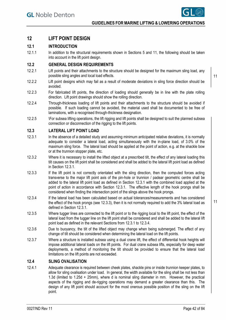
GUIDELINES FOR MARINE LIFTING & LOWERING OPERATIONS
0027/ND Rev 11 Page 42 of 84
12 LIFT POINT DESIGN
12.1 INTRODUCTION
12.1.1 In addition to the structural requirements shown in Sections 5 and 11, the following should be taken into account in the lift point design.
12.2 GENERAL DESIGN REQUIREMENTS
12.2.1 Lift points and their attachments to the structure should be designed for the maximum sling load, any possible sling angles and local load effects.
12.2.2 Lift point designs which may fail as a result of moderate deviations in sling force direction should be avoided.
12.2.3 For fabricated lift points, the direction of loading should generally be in line with the plate rolling direction. Lift point drawings should show the rolling direction.
12.2.4 Through-thickness loading of lift points and their attachments to the structure should be avoided if possible. If such loading cannot be avoided, the material used shall be documented to be free of laminations, with a recognised through-thickness designation.
12.2.5 \For subsea lifting operations, the lift rigging and lift points shall be designed to suit the planned subsea connection or disconnection of the rigging to the lift points.
12.3 LATERAL LIFT POINT LOAD
12.3.1 In the absence of a detailed study and assuming minimum anticipated relative deviations, it is normally adequate to consider a lateral load, acting simultaneously with the in-plane load, of 3.0% of the maximum sling force. The lateral load should be applied at the point of action, e.g. at the shackle bow or at the trunnion stopper plate, etc.
12.3.2 Where it is necessary to install the lifted object at a prescribed tilt, the effect of any lateral loading this tilt causes on the lift point shall be considered and shall be added to the lateral lift point load as defined in Section 12.3.1.
12.3.3 If the lift point is not correctly orientated with the sling direction, then the computed forces acting transverse to the major lift point axis of the pin-hole or trunnion / padear geometric centre shall be added to the lateral lift point load as defined in Section 12.3.1 with the combined load applied at the point of action in accordance with Section 12.3.1. The effective length of the hook prongs shall be considered when finding the intersection point of the slings above the hook prongs.
12.3.4 If the lateral load has been calculated based on actual tolerances/measurements and has considered the effect of the hook prongs (see 12.3.3), then it is not normally required to add the 3% lateral load as defined in Section 12.3.1.
12.3.5 Where tugger lines are connected to the lift point or to the rigging local to the lift point, the effect of the lateral load from the tugger line on the lift point shall be considered and shall be added to the lateral lift point load as defined in the relevant Sections from 12.3.1 to 12.3.4.
12.3.6 Due to buoyancy, the tilt of the lifted object may change when being submerged. The effect of any change of tilt should be considered when determining the lateral load on the lift points.
12.3.7 Where a structure is installed subsea using a dual crane lift, the effect of differential hook heights will impose additional lateral loads on the lift points. For dual crane subsea lifts, especially for deep water deployments, a method of monitoring the tilt should be provided to ensure that the lateral load limitations on the lift points are not exceeded.
12.4 SLING OVALISATION
12.4.1 Adequate clearance is required between cheek plates, shackle pins or inside trunnion keeper plates, to allow for sling ovalisation under load. In general, the width available for the sling shall be not less than 1.3d (limited to 1.25d + 25mm), where d is nominal sling diameter in mm. However, the practical aspects of the rigging and de-rigging operations may demand a greater clearance than this. The design of any lift point should account for the most onerous possible position of the sling on the lift point.
11
11
GUIDELINES FOR MARINE LIFTING & LOWERING OPERATIONS
0027/ND Rev 11 Page 43 of 84
12.4.2 The bearing surface of cast padears in contact with the sling shall preferably be elliptical (rather than circular) in cross-sections orthogonal to the local sling axis, see Figure 12-1. This is to allow for the flattening/ovalisation of the sling cross-section which occurs when the sling is bent and under tension which allows more of the wire strands to work. It is not possible to generalise on dimensions for this purpose, as each sling would deform by a different amount, depending on the load that it is required to take. The sling arrangement should therefore be closely examined at an early stage in order to determine the amount of deformation which will need to be allowed for in the padear design.
Figure 12-1 Indicative shaping of padear bearing surface
12.5 PADEYES
12.5.1 The outside radius of the padeye main plate shall be no less than the diameter of the pin hole.
12.5.2 Pin-holes should be bored / reamed, and should be designed to suit the shackle proposed. The pin hole diameter shall be 2 mm or 3% larger than the diameter of the shackle pin, whichever is the greater, up to a maximum of 6 mm.
12.5.3 When determining the pin-hole diameter, the tolerance on the pin diameter should also be considered to ensure that the pin will enter the pin hole on the lift point.
12.5.4 The pad eye thickness at the hole shall not be less than 75% the inside width of the shackle.
12.5.5 The total thicknesses of cheek plates on one side of the main plate should not exceed 100% of the main plate thickness. The cheek plates should be symmetric either side of the main plate.
12.5.6 Non-load bearing spacer plates may be used to centralise shackle pins, by effectively increasing the padeye thickness. The diameter of the internal hole in such spacer plates shall be greater than the pin hole diameter. Spacer plates, if used, shall provide a 20-30 mm clearance to the inside width of the shackle (i.e. 10 to 15 mm each side).
12.5.7 Cheek plate welds shall be proportioned and designed with due regard to possible uneven bearing across the padeye/cheek plate thickness due to combined nominal (3%) and actual lateral loads.
12.5.8 It is permissible to use the nominal shackle pin diameter and hole diameter in the strength calculations for the lift point provided the tolerance on the hole diameter is acceptable to GL Noble Denton.
12.6 CAST PADEARS AND WELDED TRUNNIONS
12.6.1 Cast padears and trunnions shall be designed taking into account the following aspects:
The geometrical considerations as indicated in Section 12.4.
The stress analysis and finite element design process (modelling and load application).
Load paths, trunnion geometry and space and support for slings and grommets.
The manufacturing process and quality control.
Sling keeper plates shall be incorporated into the padear/trunnions design to prevent the loss of slings or grommets during load application and lifting. These devices shall be proportioned to allow easy rigging and de-rigging whilst being capable of supporting the weight of the sling section during transportation.
12.7 INSPECTION OF LIFT POINTS
12.7.1 All lift points shall be inspected prior to any lifting operation. For the first lift, the level of inspection for welds which form part of the load transfer system in the lift point shall be:
a. 100% visual for all welds, and b. 100% MPI (Magnetic Particle Inspection) for all fillet welds, partial penetration welds and butt
welds, and c. 100% UT (Ultrasonic Testing) for all butt welds.
11
11
11
GUIDELINES FOR MARINE LIFTING & LOWERING OPERATIONS
0027/ND Rev 11 Page 44 of 84
12.7.2 For subsequent lifting operations using the same lift points, a visual inspection will be adequate provided that:
a. The visual inspection shows no damage to the lift point material and welding b. The rigging system is similar to that used for previous lifts and that the lift points have been
designed for that rigging system c. No excessive or uncontrolled loading has, or suspected to have, occurred during the preceding
lifts d. All design utilisations for primary load transfer in the lift points are less than 0.8.
12.7.3 Where the visual inspection shows that damage has occurred, appropriate repairs are to be taken which shall be subject to the 100% visual, MPI and UT requirements given in Section 12.7.1.
12.7.4 Where excessive or uncontrolled loading has occurred, and member /weld utilisations are less than 0.8, all primary welds are to be inspected with 100% visual and 50% MPI with butt welds also tested with 50% UT.
12.7.5 Where excessive or uncontrolled loading has occurred, and member /weld utilisations are greater than 0.8, all primary welds are to be inspected with 100% visual and 100% MPI with butt welds also tested with 100% UT.
12.7.6 Where the rigging system used is different to the design rigging system, all primary welds are to be inspected with 100% visual and 100%MPI with butt welds also tested with 100%UT.
12.7.7 For lift points with utilisations of primary load transfer members /welds greater than 0.8, the level of inspection shall be a minimum of 100% visual, 20%MPI with butt welds also tested with 20%UT.
12.7.8 The extent of NDT shall be submitted for review.

GUIDELINES FOR MARINE LIFTING & LOWERING OPERATIONS
0027/ND Rev 11 Page 45 of 84
13 FABRICATION YARD LIFTS
13.1 INTRODUCTION
13.1.1 This section is applicable to lifts and other crane assisted operations (e.g. jacket roll-up operations) in connection with erection and assembly. It also applies to load-out and load-in operations by onshore cranes.
13.1.2 Relevant requirements in Sections 4 to 12 apply for major yard lifts, roll-up operations and load out / load in operations by lifting. The following sections describe exemptions and additional requirements for such operations.
13.2 WEIGHT AND COG
13.2.1 The weight of a yard lifted item is often based on calculation only. In such cases, a minimum weight contingency factor of 1.1 should be used to define the design weight.
13.2.2 The effect of extreme positions of the CoG should be evaluated for the design of the structure, supports and lifting system.
13.3 ADDITIONAL LOADS
13.3.1 For roll-up operations, additional loads may be of significant importance and should be thoroughly evaluated. Additional loads for roll-up would typically include the following
a) winch/tugger line loads
b) support reaction loads (vertical and horizontal) c) friction loads (at supports and slings) d) wind loads
e) settlement of supports
13.3.2 Fabrication yard lifts may involve three or more cranes. Extreme crane loads, i.e. worst possible load distributions within the cranes, should be calculated considering, at least, the following:
a) support lay-out defined by the cranes
b) flexibility of the lifted object c) crane types d) limiting environmental conditions e) lifting procedure f) monitoring system/tolerances
A sensitivity analysis considering possible crane load variations should be considered.
13.3.3 The design of the lifted structure and lifting equipment should in some cases be based on the crane extreme load capacity, e.g. overturning load for crawler crane. This is particularly relevant for lifting with several highly utilised crawler cranes in a statically indeterminate arrangement where exact crane loads may be difficult to control.
13.3.4 For operations involving multiple cranes, the maximum out of plumb of the hoist lines should be defined/calculated and considered in the calculations.
13.3.5 The effect of swinging of the lifted object due to travelling crane movements should be evaluated.
13.3.6 The design of lifting equipment should in some cases be based on the crane extreme load capacity, e.g. overturning load for crawler crane. This is particularly relevant for lifting with several highly utilised crawler cranes, where exact crane load may be difficult to control.
13.4 DYNAMIC LOADS
13.4.1 The applicable Dynamic amplification factors (DAF) for onshore lifts are given in Table 5-1 in Section 5.5.
13.4.2 For crawler cranes travelling with a suspended load, the possible dynamic effects should be evaluated thoroughly. Crane speeds and surface conditions should be considered. If no documentation is presented the minimum factors for “inshore lifts” in Table 5-1 should be used.
11

GUIDELINES FOR MARINE LIFTING & LOWERING OPERATIONS
0027/ND Rev 11 Page 46 of 84
13.5 LOAD CASES
13.5.1 Load cases for fabrication yard lifts should be based on the general guidelines in Sections 5 to 9 and 11 to 12.
13.5.2 For multi-crane operations, a sensitivity analysis with respect to possible crane load distributions (see Section 13.3.2) should be carried out.
13.5.3 For roll-ups, the analysis should be carried out to include an adequate number of roll-up angles. Where it is noted that there is the possibility for higher loads in the rigging system, higher stresses in the lifted structure etc. to occur between the angles selected, then intermediate steps between the selected angles should be considered.
13.6 LIFTING EQUIPMENT
13.6.1 Slings and grommets should be designed based on the requirements of Section 7.
13.6.2 Attention should be paid to the effect of object rotation (roll-up) on sling connections. Additionally, the effect of any unequal load distribution in the legs of slings should be considered if the structure rotates about the sling eye or a doubled sling (see Section 5.8.2).
13.6.3 Shackles with a WLL 50 tonnes without certification may be accepted, provided:
a) the WLL is stamped on the shackle
b) the original manufacturer is recognised
c) calculated dynamic shackle load WLL d) the shackle is thoroughly inspected before use
13.7 FABRICATION YARD CRANES
13.7.1 Fabrication yard cranes should normally possess an approval, issued by a recognised authority.
13.7.2 It should be documented that regular maintenance is carried out for all parts of the crane important for the safety of the lift.
13.7.3 Allowable crane loads should be based on load-radii curves/tables. These should, as applicable, clearly state:
a) Crane boom type and length. b) Counter weight position(s) and minimum number of hoist line legs. c) Maximum load, limited by overturning or structural strength. d) Crane equipment, e.g. hook, block, hoist lines, jib, to be included in crane hook load. e) Operational limitations.
13.7.4 For multiple crane operations involving travelling, effective crane radii should be calculated considering maximum out of plumb for hoist lines. The crane capacities should be calculated based on these radii. See section 13.3.4 and 13.3.5 for further details.
13.7.5 Adequate sub-structure / ground strength should be documented for the supports of any crane outriggers and crawler crane operations, especially, for example, in areas over culverts, drains, underground services, proximity to the edge of an excavation, quayside locations, etc. Special attention should be given to toe peak loads of the crawler crane tracks, areas which has been recently back-filled or areas susceptible to reduced strength following inclement weather.
13.7.6 If there is insufficient information regarding ground capacity, load testing (including the complete crane track) shall be carried out.
13.7.7 Operational limitations for travelling counter weights should be considered and the position and weight should be checked.
13.8 OPERATIONAL AND PRACTICAL CONSIDERATIONS FOR ONSHORE LIFTS
13.8.1 Assuming all effects have been assessed, a calculated minimum clearance to the crane boom of 0.5 m is normally acceptable. For roll-up operations planned hoist line angles need to be considered when the minimum clearances are calculated and, for lifts involving travelling cranes, possible deviations from vertical hoist lines (see Section 13.7.4) need to be considered when establishing minimum clearances for lifts.
11

GUIDELINES FOR MARINE LIFTING & LOWERING OPERATIONS
0027/ND Rev 11 Page 47 of 84
13.8.2 Accessible areas within the swing radius of a rotating crane and counterweight shall be barricaded to prevent personnel from being struck or crushed by the counterweight.
13.8.3 A minimum clearance distance of 600 mm is to be maintained at all times between the slewing part of the crane and adjacent hazard or structure to prevent potential crushing of personnel.
13.8.4 Crane tracks should be marked and the surface levelled/improved if required.
13.8.5 A thorough check for obstructions in way of the cranes, structure and rigging should be carried out. This also applies to overhead lines and the minimum clearance requirements to overhead lines (e.g. power lines) shall be in accordance with local or national requirements.
13.8.6 It shall be ensured by surveys and monitoring (e.g. crane boom radius/boom angle, load readings, structure level etc.) that all allowable load assumptions are properly accounted for (see Sections 13.7.3 to 13.7.7). For roll-up operations, monitoring should include:
a) Lifted/upended object deflections
b) hoist line angles c) crane positions d) reaction loads/behaviour in roll up cells e) roll-up angle f) clearances e.g. of the structure to crane booms
13.8.7 Where relevant, additional considerations for offshore lifts will be applicable for onshore lifting operations. Details for these can be found in Section 18.
11

GUIDELINES FOR MARINE LIFTING & LOWERING OPERATIONS
0027/ND Rev 11 Page 48 of 84
14 FABRICATION OF RIGGING AND LIFTING EQUIPMENT
14.1 INTRODUCTION
14.1.1 The following section covers the fabrication of slings, grommets, shackles and other lifting equipment. The details contained in the following sections should be considered the minimum requirements as it may be that national standards, local standards or operator/contractor requirements may be more onerous.
14.2 MATERIALS AND CONSTRUCTION OF STEEL SLINGS AND GROMMETS
14.2.1 The construction of steel slings and grommets should be according to a recognised code and method e.g. grommets are constructed and used in accordance with IMCA guidance, Ref. [7].
14.2.2 Steel slings or grommets may be constructed from a single wire rope, or for cable laid slings or grommets, constructed from multiple wire ropes.
14.2.3 The quality and performance characteristics of all materials used in slings and grommets shall be adequate and documented.
14.2.4 The minimum breaking load (MBL) of steel wire-rope slings and grommets shall be documented (and certified) in accordance with a recognised standard. Documentation should clearly indicate how the stated MBL has been determined.
14.2.5 Ideally, the MBL for wire rope should be determined by pulling a complete rope to destruction. Where adequate facilities are not available for such testing, the wire rope MBL should be established in accordance with a recognised standard.
14.2.6 When fabricating steel slings or grommets from several individual ropes, the total MBL should normally be taken as the sum of the unit rope MBLs, divided by a sling spinning loss factor of 1.18. For grommets, the strength of the core element should not be included when calculating the MBL.
14.2.7 The sling eye length for cable laid slings should be no shorter than specified by the manufacturer or less than 10 times the rope diameter. The eye length should also suit the intended lift point detail (hook prong, shackle bow, etc.) and normally ensure that the internal opening angle of the sling does not exceed 20°. Where a sling eye internal opening angle exceeds 20°, it must be documented that the sling is still suitable for the intended use, allowing for any reduction in the capacity of the sling. The documentation supplied should include calculations and confirmation from the sling supplier of any reduction in the capacity of the sling.
14.2.8 Lengths and tolerances of steel slings and grommets should be adequately specified in order to fulfil the assumptions for the applied skew load SKL, see Section 5.6.
14.2.9 The length of steel slings and grommets should be documented by adequate measurements. During measuring, slings or grommets should be fully supported and adequately tensioned. The test tension should be agreed with the manufacturer and normally be in the range of 2.5% to 5.0% of the MBL. Matching slings should be measured with the same tensile load and under similar conditions. The tension and the bending diameter during the tensioning test should be specified on the test certificate.
14.2.10 If needed, the lengths should be measured at adequate tensions to establish the Elastic Modulus (E) if required in the determination of the skew load factor, see Sections 5.6.8 to 5.6.13.
14.2.11 Slings with hand spliced terminations must be prevented from rotation when the slings are loaded.
14.2.12 Steel slings or grommets required to be wet stored for an extended period prior to use (e.g. for the recovery of a subsea asset) shall have adequate resistance against all possible mechanisms of degradation and the material properties shall be documented accordingly. For certification requirements, see Section 15.2.4.
14.3 MATERIALS AND CONSTRUCTION OF FIBRE SLINGS AND GROMMETS
14.3.1 The construction of fibre slings and grommets should be according to a recognised code and method.
14.3.2 Lifting slings and grommets may be manufactured using polyester, high-modulus polyethylene (HMPE), aramid or other synthetic fibre materials. The quality and performance characteristics of all materials used shall be adequate and documented.
11

GUIDELINES FOR MARINE LIFTING & LOWERING OPERATIONS
0027/ND Rev 11 Page 49 of 84
14.3.3 Minimum breaking load (MBL) for fibre slings and grommets should be established on the basis of destructive tests, using complete rope specimens. It is normally acceptable to define the MBL as the lowest value of three tests, however defining the MBL based on the 5th percentile of results is recommended.
14.3.4 For large fibre slings where destructive testing of whole specimens is not possible, an alternative method of establishing the MBL may be deemed acceptable in the certification process.
14.3.5 When testing fibre slings to determine the MBL, the fibre slings may be subjected to a "bedding-in" procedure of 10 cycles to 50% of the predicted MBL before testing to destruction.
14.3.6 For the purposes of testing, fibre grommets shall be bent around the minimum permissible bending diameter during normal use and the minimum bend diameter should be marked on the identity tag. If any parts of a fibre sling, other than the eyes, will be bent during normal use, such bending should be included during MBL testing.
14.3.7 For fibre slings and grommets the maximum and minimum operating temperature shall be defined and clearly specified.
14.3.8 Fibre slings should normally be proof load tested before being used for the first time. The proof load
for fibre slings should be as listed below, with the WLL = MBLsling / sf. For sf see Section 7.3.
For a WLL ≤ 25 tonnes the proof load shall be 2 x WLL;
For a WLL > 25 tonnes the proof load shall be 1.22 x WLL + 20 tonnes
14.3.9 Lengths and tolerances of fibre slings and grommets should be adequately specified in order to fulfil the assumptions for the applied skew load factor (SKL), see Section 5.6.
14.3.10 The length of fibre slings and grommets should be documented by adequate measurements. During measuring, slings or grommets should be fully supported and adequately tensioned. The test tension should normally be in the range of 2.5% to 5.0% of the MBL. Matching slings should be measured with the same tensile load and under similar conditions. The tension and the bending diameter during the tensioning test should be specified on the test certificate. All measurements are to be taken after the proof load test is carried out, see 9.3.8.
14.3.11 Fibre slings or grommets required to be wet stored for an extended period prior to use (e.g. for the recovery of a subsea asset) shall have adequate resistance against all possible mechanisms of degradation and the material properties shall be documented accordingly. For certification requirements, see Section 15.2.4.
14.4 MATERIALS AND CONSTRUCTION OF SHACKLES
14.4.1 The construction of shackles should be according to a recognised code and method.
14.4.2 Every shackle should be proof load tested after fabrication. The proof load for shackles should be as listed below.
For a WLL ≤ 25 tonnes the proof load shall be 2 x WLL;
For a WLL > 25 tonnes the proof load shall be 1.22 x WLL + 20 tonnes
14.4.3 A shackle shall not be used if the inspection after the proof loading reveals any geometrical deformations, cracks, or other defects.
14.4.4 Shackles required to be wet stored for an extended period prior to use (e.g. for the recovery of a subsea asset) shall have adequate resistance against all possible mechanisms of degradation and the material properties shall be documented accordingly. For certification requirements, see Section 15.3.11.
14.5 MATERIALS AND CONSTRUCTION OF LIFTING TOOLS
14.5.1 The construction of lifting tools should be according to a recognised code and method.
14.5.2 All material shall be suitable for the intended service conditions and shall have adequate properties of strength, ductility, toughness and weldability.
14.5.3 All material should be certified with traceability of material used in the fabrication of the lifting tool.
14.5.4 All hydraulic activated lifting tools shall be pressure tested to 1.5 x the design pressure.
11

GUIDELINES FOR MARINE LIFTING & LOWERING OPERATIONS
0027/ND Rev 11 Page 50 of 84
14.5.5 If used, the hydraulic systems should be ‘fail-safe’ in nature, i.e. in the event of hydraulic power loss, the tool will continue to transmit normal operating loads.
14.5.6 All relevant test certificates shall be issued by an IACS member (see Section 10.2.1 for IACS details) or other recognised certification body accepted by GL Noble Denton.
14.5.7 Automatic lifting tools shall have systems in place to control the stress in the lifted item in order to prevent excessive local stress for sensitive items. Redundant mechanical systems must be in place in case of power loss.
14.5.8 Operating and monitoring procedures of lifting tools should be adequate to ensure the prevention of all critical and foreseeable operational errors. External and internal hydraulic lifting tools should have:
a remote monitoring system close to/visible from the crane driver’s cab;
a pressure gauge (or indicator) in the system, showing when the tool is closed or open
a duplicate pressure gauge (or indicator), as close as safely possible to the tool to avoid influences in pressure reading
a secondary method of release in the event of hydraulic system failure
14.6 MATERIALS AND CONSTRUCTION OF SPREADER BARS AND SPREADER FRAMES
14.6.1 The material selection, fabrication method and NDT should be carried out in accordance with a recognised code.
14.6.2 All material shall be suitable for the intended service conditions and shall have adequate properties of strength, ductility, toughness and weldability.
14.6.3 All material should be certified with traceability of material used in the fabrication of the spreader bar / frame.
14.6.4 The as-built fabrication package for the spreader bar / frame should be made available for inspection as required and contain, as a minimum, the following:
Material Certificates,
Traceability of materials,
Welding procedure specifications and qualification for the procedures,
Welding consumable certificates,
Traceability details for welds
NDT report,
Heat treatment reports (if required)
Dimensional reports
Certificates for welding personnel
Certificates for NDT personnel
Weight report (if required)
As-built drawings
Release Note and any external certification.
14.6.5 For a spreader bar / frame which is to be used on projects where there are more than 10 lifts or the spreader bar / frame is rented in from an external supplier, the spreader bar and rigging shall be load tested to, as a minimum, 1.25 x Dynamic Lift Load (where the Dynamic Lift Load is based on the maximum static load of the lifted structure, including rigging below the spreader bar, multiplied by the appropriate DAF – see Section 5.5). The allowable maximum static load (i.e. the static load used in the derivation of the Dynamic Lift Load for the load test) and the applicable DAF used on the load test and rigging configuration(s) applicable to the load test shall be clearly stated on the spreader bar / frame or the load test certificate.
14.6.6 For a spreader bar / frame which is to be used on projects where there are less than 10 lifts, the requirement for load testing is not required provided the spreader bar / frame is designed in
11
GUIDELINES FOR MARINE LIFTING & LOWERING OPERATIONS
0027/ND Rev 11 Page 51 of 84
accordance with these guidelines and a full fabrication specification (see Section 14.6.4) are provided for review.
14.6.7 For any existing spreader bar / frame which is modified for lifting operations, the existing as-built package is to be updated with the relevant requirements of Section 14.6.4. For load testing, the requirements, of Sections 14.6.5 or 14.6.6 are also applicable.
14.6.8 Spreader bars / spreader frames required to be wet stored for an extended period prior to use (e.g. for the recovery of a subsea asset) shall have adequate resistance against all possible mechanisms of degradation and the material properties shall be documented accordingly. Consideration should also be given to the use of anodes attached to the bars or frames if there are concerns about possible degradation.
14.7 MATERIALS AND CONSTRUCTION OF OTHER LIFTING EQUIPMENT
14.7.1 For lifting beams, the requirements of 14.6.1 to 14.6.4 apply and the equipment shall be subject to a proof load test in accordance with the following requirements
For a WLL ≤ 10 tonnes the proof load shall be 2 x WLL;
For 10 tonnes < WLL ≤ 160 tonnes the proof load shall be (1.04 x WLL) + 9.6 tonnes;
For a WLL > 160 tonnes the proof load shall be 1.1 x WLL
14.7.2 Other lifting equipment, as defined in section 9.3.5, shall be designed, manufactured and tested according to a recognised code for such equipment and shall be delivered with adequate certification.
14.7.3 The WLL shall be clearly marked on the equipment and the certification along with any limitations on the applied load.
14.7.4 Other lifting equipment required to be wet stored for an extended period prior to use (e.g. for the recovery of a subsea asset) shall have adequate resistance against all possible mechanisms of degradation and the material properties shall be documented accordingly. For certification requirements, see Section 15.6.6.
14.7.5 For single sheave blocks, the equipment shall be subject to a proof load test in accordance with the following requirements
The proof load shall be 4 x WLL (4 x WLL is the load applied to the head fitting i.e. each leg of the fall on the sheave is to be 2 x WLL);
Note, the WLL of a single sheave block, with or without beckets, shall be taken as 50% of the resultant load on the head fitting.
14.7.6 For multiple sheave blocks, the equipment shall be subject to a proof load test in accordance with the following requirements
For a WLL ≤ 25 tonnes the proof load shall be 2 x WLL;
For 25 tonnes < WLL ≤ 160 tonnes the proof load shall be (0.933 x WLL) + 27 tonnes;
For a WLL > 160 tonnes the proof load shall be 1.1 x WLL
Note, the WLL of a multiple sheave block shall be taken as the resultant load on the head fitting.
14.7.7 For items such as chains, hooks, swivels, etc., the equipment shall be subject to a proof load test in accordance with the following requirements
For a WLL ≤ 25 tonnes the proof load shall be 2 x WLL;
For a WLL > 25 tonnes the proof load shall be (1.22 x WLL) + 20 tonnes
11

GUIDELINES FOR MARINE LIFTING & LOWERING OPERATIONS
0027/ND Rev 11 Page 52 of 84
15 CERTIFICATION AND INSPECTION OF RIGGING AND LIFTING EQUIPMENT
15.1 INTRODUCTION
15.1.1 The following section covers the certification of rigging equipment listed in Section 14. The details contained in the following sections should be considered the minimum requirements as it may be that national standards, local standards or operator/contractor requirements may be more onerous.
Reference in the following sections will be made to certification issued by an International Association of Classification Societies (IACS) member and a listing of IACS members is given on the IACS web site
http://www.iacs.org.uk/explained/members.aspx
15.1.2 Reference in the following sections will be made to certification issued by a “Competent Person”. A Competent Person is defined as follows and is based on the definition in LOLER 98 (see Reference [12]):
A Competent Person carrying out a thorough examination shall have such appropriate practical and theoretical knowledge and experience of the lifting equipment to be thoroughly examined as will enable them to detect defects or weaknesses and to assess their importance in relation to the safety and continued use of the lifting equipment. Although the competent person may often be employed by another organisation, this is not necessary, provided they are sufficiently independent and impartial to ensure that in-house examinations are made without fear or favour. However, this should not be the same person who undertakes routine maintenance of the equipment as they would then be responsible for assessing their own maintenance work.
Note, where local or national regulations define a Competent Person with more onerous requirements, then the definition in these local or national regulations shall apply.
15.2 CERTIFICATION, INSPECTION AND REVALIDATION OF SLINGS AND GROMMETS
15.2.1 All lifting equipment shall be in good condition and thoroughly inspected before each lift or series of lifts. Special attention should be given to the condition of splices and terminations.
15.2.2 For slings and grommets used for offshore and inshore lifting, a valid certificate issued by a Competent Person is to be provided showing that the sling or grommet has been inspected within the past 6 months. The exception to this are slings and grommets used for general deck activities on the crane vessel for which the onshore requirements are applicable provided there are no over the side lifts in which case the offshore requirements still apply.
15.2.3 For slings and grommets used for onshore lifting, a valid certificate issued by a Competent Person is to be provided showing that the sling or grommet has been inspected within the past 12 months. The exceptions to this are slings and grommets used for the load-out operations to/from a vessel of structures and any essential equipment required for its subsequent installation, for which the offshore requirements are applicable.
15.2.4 For slings or grommets required to be wet stored for an extended period prior to use (e.g. for the recovery of a subsea asset), if the storage period is anticipated beyond the inspection interval, the means for satisfying any formal or regular inspection requirements should be agreed. The fabrication requirements for wet stored slings and grommets are referenced in Section 14.2.12 for steel slings and Section 14.3.11 for fibre slings.
15.2.5 For slings and grommets, a Manufacturer’s Certificate corresponding to the requirements in EN 10204, Ref. [13], type 3.1 (or type 3.2) should be provided. For slings or grommets made of steel wire ropes and used with a material factor of less than 1.5 (see Section 7.10.2), a 3.2 certificate (as defined in EN 10204, issued or endorsed by a recognised Certifying Body) is required.
15.2.6 Safety factors and other restrictions or limitations imposed by other relevant directives/standards in a Declaration of Conformity (if accepted as adequate certification) shall be adhered to. However, the level of safety shall not be less than stated in this guideline. Note: a Declaration of Conformity is a document signed and issued by the manufacturer to confirm the product meets all of the requirements of the applicable directives.
11

GUIDELINES FOR MARINE LIFTING & LOWERING OPERATIONS
0027/ND Rev 11 Page 53 of 84
15.2.7 The sling/grommet certificate should indicate as a minimum:
unique identification number/s,
name of manufacturer,
date of manufacture,
clearly defined MBL,
diameter and length (nominal and actual/measured),
type of construction,
applied proof load (if applicable)
Modulus of Elasticity (E), if applicable – see Section 14.2.10.
15.2.8 In addition to Section 15.2.7, the following information for cable laid slings or grommets should be included:
certificate number/s for component unit ropes (certificate/s to be enclosed),
MBL of component ropes,
MBL of sling or grommet.
15.2.9 In addition to Section 15.2.7, the following information for fibre slings or grommets should be included:
minimum bend diameter,
reject criteria,
maximum working temperature,
applied proof load (if applicable).
15.2.10 Each sling or grommet should be clearly identified with reference to the corresponding certificate.
15.2.11 Slings and grommets shall be discarded, or subject for revalidation/re-certification according to 15.2.15, if any of the following are applicable:
apparent damage or deterioration,
indications of previous overloading,
unknown internal condition,
unreliable handling or storage history. 15.2.12 Where 9-part slings are proposed for use in a lifting system, certification of these slings shall be given
special consideration.
15.2.13 For slings and grommets used for offshore and inshore lifting, the inspection report signed by a recognised Certifying Body should be valid for 2 years. The exception to this are slings and grommets used for general deck activities on the crane vessel for which the onshore requirements are applicable provided there are no over the side lifts in which case the offshore requirements still apply.
15.2.14 For slings and grommets used for onshore lifting, the inspection report signed by a recognised Certifying Body should be valid for 4 years. The exceptions to this are slings and grommets used for the load-out operations to/from a vessel of structures and any essential equipment required for its subsequent installation, for which the offshore requirements are applicable.
15.2.15 Where revalidation/re-certification is required, the slings and grommets shall be thoroughly inspected and evaluated by a competent person from a recognised sling manufacturer and / or Certifying Body. Destructive testing and issuance of new certificates, when required, shall be done by a recognised sling / grommet manufacturer and/or Certifying Body. Revalidation/re-certification procedures should be according to a recognised code and normally include the elements indicated below:
Slings and grommets subject for revalidation should be properly cleaned. Random opening should be carried out to check for internal condition and corrosion. The number of openings is subject to the length of the sling, but as a minimum the sling should be opened in at least three different locations.
A rope, or unit ropes of one sling (if cable laid) in a series of used slings should be subject to destructive testing, if there are uncertainties with respect to capacity or internal conditions of the series.
The nominal length of slings as specified in their original certificates should be verified or re-determined by measuring under tension, prior to issuance of new certificate. For tension requirements, see Sections 14.2.9 and 14.2.10.
11

GUIDELINES FOR MARINE LIFTING & LOWERING OPERATIONS
0027/ND Rev 11 Page 54 of 84
15.2.16 For heavy duty slings and grommets (typically with MBL greater than 500t) a data/log book should be maintained and should contain, as a minimum, the following
all relevant certificates,
survey reports,
handling and storage/conservation procedure,
storage history.
For cable laid slings and grommets, the following additional information should also be included in the data/log book for each cable laid sling and grommet:
records of previous lifts,
lift weights and expected loading in each sling / grommet,
minimum bend radius.
15.3 CERTIFICATION AND INSPECTION OF SHACKLES
15.3.1 All shackles shall be in good condition and thoroughly inspected before each lift or series of lifts. Special attention should be given to ensure there are no deformations, cracks or other defects and that there are no indications of abnormal loading.
15.3.2 When shackles are used on a regular basis, a visual inspection shall be carried out by a Competent Person before any lift when the utilisation of the shackle will be more than 80% of the WLL.
15.3.3 For shackles used for offshore and inshore lifting, a valid certificate issued by a Competent Person is to be provided showing that the shackle has been inspected within the past 6 months. The exception to this are shackles used for general deck activities on the crane vessel for which the onshore requirements are applicable provided there are no over the side lifts in which case the offshore requirements still apply.
15.3.4 For shackles used for onshore lifting, a valid certificate issued by a Competent Person is to be provided showing that the shackle has been inspected within the past 12 months. The exceptions to this are shackles used for the load-out operations to/from a vessel of structures and any essential equipment required for its subsequent installation, for which the offshore requirements are applicable.
15.3.5 All shackles shall be inspected every 2 years with MPI and UT to confirm there are no defects.
15.3.6 A manufacturer’s certificate and proof load certificate signed by a recognised Certifying Body should be provided for each shackle.
15.3.7 For shackles used for offshore and inshore lifting, the inspection and NDT report signed by a recognised Certifying Body should be valid for 2 years. The exception to this are shackles used for general deck activities on the crane vessel for which the onshore requirements are applicable provided there are no over the side lifts in which case the offshore requirements still apply.
15.3.8 For shackles used for onshore lifting, the inspection and NDT report signed by a recognised Certifying Body should be valid for 4 years. The exceptions to this are shackles used for the load-out operations to/from a vessel of structures and any essential equipment required for its subsequent installation, for which the offshore requirements are applicable.
15.3.9 For shackles required to be wet stored for an extended period prior to use (e.g. for the recovery of a subsea asset), if the storage period is anticipated beyond the inspection interval, the means for satisfying any formal or regular inspection requirements should be agreed. The fabrication requirements for wet stored shackles are referenced in Section 14.4.4.
15.3.10 Each shackle should be clearly identified with reference to the corresponding certificate. The safe working load as specified in the certificate should be clearly marked on the shackle.
15.3.11 A shackle certificate should normally contain the following minimum information:
Certificate identification code
Shackle identification code
MBL
Proof load
Safe working load
11
GUIDELINES FOR MARINE LIFTING & LOWERING OPERATIONS
0027/ND Rev 11 Page 55 of 84
Name of manufacturer
Date of manufacture
Material type
Manufacturing method
Reference code, standard or specification
Date of certification.
15.4 CERTIFICATION AND INSPECTION OF LIFTING TOOLS
15.4.1 All lifting tools shall be in good condition and thoroughly inspected before each lift or series of lifts. Special attention should be given to the condition of the grippers and the hydraulic system (where fitted) to ensure there is no corrosion or leaks.
15.4.2 Relevant test certificates shall be issued or endorsed by a body approved by an IACS member (see Section 10.2.1 for IACS details).
15.4.3 The test certificate referenced in Section 15.4.2 shall be valid for a maximum of 4 years and the lifting tool is to be inspected every 6 months by a Competent Person.
15.5 CERTIFICATION AND INSPECTION OF SPREADER BARS AND SPREADER FRAMES
15.5.1 All spreader bars / frames shall be in good condition and thoroughly inspected before each lift or series of lifts. Special attention should be given to ensure there are no deformations, cracks or other defects, there is no corrosion other than surface scale, the bearing surfaces at the rigging connection points are in a good condition and that there are no indications of abnormal loading.
15.5.2 For a spreader bar / frame which is to be used for repetitive operations where there are more than 10 lifts, a load test certificate shall be supplied and shall specify the allowable static load, the applicable DAF and applicable rigging arrangement (see Section 14.6.5).
15.5.3 For a spreader bar / frame which is to be used for repetitive operations (see Section 14.6.5 for load test and certificate requirements), the spreader bar / frame shall be subjected to periodic NDT inspection based on the utilisation of the spreader bar to the following requirements:
For a spreader bar / frame utilised at 90 to 100% of the WLL, NDT is to be carried out after 20 lifts or 50 hours of use, whichever is earliest;
For a spreader bar / frame utilised at 70 to 90% of the WLL, NDT is to be carried out after 40 lifts or 100 hours of use, whichever is earliest;
For a spreader bar / frame utilised at below 70% of the WLL, no periodic NDT is required.
The level of inspection shall be 100% of welds at the lift point area and 50% of welds on areas away from the lift point. The NDT testing shall be visual for all welds, MPI for fillet, partial penetration and butt welds with butt welds also tested with UT.
15.5.4 Where excessive or uncontrolled loading has occurred, the spreader bar / frame shall be subject to NDT. This is to be carried out with all welds 100% visual, all welds 100% MPI with butt welds also tested with 100% UT.
15.5.5 Where spreader bars or spreader frames are modified, the requirements of Section 14.6 are to be carried out where applicable.
15.5.6 For spreader bars or spreader frames to be wet stored for an extended period prior to use (e.g. for the recovery of a subsea asset), the means for satisfying any pre-lift inspection requirements should be agreed. The fabrication requirements for wet stored spreader bars or spreader frames are referenced in Section 14.6.8.
15.6 CERTIFICATION AND INSPECTION OF OTHER LIFTING EQUIPMENT
15.6.1 For the definition of “other lifting equipment”, see Section 9.3.5.
15.6.2 All other lifting equipment shall be in good condition and thoroughly inspected before each lift or series of lifts.
15.6.3 All other lifting equipment shall be provided with a proof loading certificate with the loading in accordance with the relevant section of Section 14.7.
11

GUIDELINES FOR MARINE LIFTING & LOWERING OPERATIONS
0027/ND Rev 11 Page 56 of 84
15.6.4 For other lifting equipment used as part of an offshore or inshore lifting system, a valid certificate issued by a Competent Person is to be provided showing that the item has been inspected within the past 6 months. The exception to this are items used for general deck activities on the crane vessel for which the onshore requirements are applicable provided there are no over the side lifts in which case the offshore requirements still apply.
15.6.5 For other lifting equipment used as part of an onshore lifting, a valid certificate issued by a Competent Person is to be provided showing that the item has been inspected within the past 12 months. The exceptions to this are items used for the load-out operations to/from a vessel of structures and any essential equipment required for its subsequent installation, for which the offshore requirements are applicable.
15.6.6 For other lift equipment required to be wet stored for an extended period prior to use (e.g. for the recovery of a subsea asset), if the storage period is anticipated beyond the inspection interval, the means for satisfying any formal or regular inspection requirements should be agreed. The fabrication requirements for other lift equipment which is wet stored are referenced in Section 14.4.4.
11

GUIDELINES FOR MARINE LIFTING & LOWERING OPERATIONS
0027/ND Rev 11 Page 57 of 84
16 CLEARANCES
16.1 INTRODUCTION
16.1.1 The required clearances will depend on the nature of the lift, the proposed limiting weather conditions, the size and weight of the lifted object, ability to control the lift, consequence of impact loads and the arrangement of bumpers and guides.
16.1.2 When evaluating clearances the effect of the maximum motions of the crane vessel associated with the environmental design conditions and DP / mooring system capability should be considered. For clearances on the transport barge, the motions of the transport barge should also be considered in addition to the motions of the crane vessel.
16.1.3 Subject to the above, for offshore lifts, the following clearances highlighted in sections 16.2, 16.3, 16.4 and 16.5 should normally be maintained at each stage of the operation. Smaller clearances may be acceptable for inshore or onshore lifts. Clearances are based on a level lift (no tilt) of each structure. Additional clearances may be required for structures with a prescribed tilt.
16.2 CLEARANCES AROUND LIFTED OBJECT (FLOATING CRANE)
16.2.1 3 metres between any part of the lifted object (including rigging, spreaders and lift points) and the crane boom, when the load is suspended.
16.2.2 3 metres vertical clearance between the underside of the lifted object and any other previously installed structure. For the final stages of the lifting operation when the lifted object is in the immediate vicinity of the proposed landing area or installation aid, lowering of the lifted object can commence and a 1.5 metre clearance shall be adequate prior to moving the lifted object into its final position above the proposed landing area or installation aid.
16.2.3 5 metres between the lifted object and other structures on the same transport barge unless bumpers and guides are used for lift-off.
16.2.4 3 metres horizontal clearance between the lifted object, rigging or crane wire and any other structures, including the installation vessel, unless purpose-built guides or bumpers are fitted.
16.2.5 3 metres remaining travel between travelling block and fixed block at the maximum required load elevation with the lift vessel at LAT. “Remaining travel” excludes any travel prevented by system limits that cannot be over-ridden for this operation/
16.2.6 Where a structure is securely engaged within a bumper/guide or pin/bucket system, clearance between the extremities of the structure and the host structure must be demonstrated to be positive, considering the worst possible combinations of tilt. This may require dimensional control surveys to be carried out on the host structure and the structure to be installed.
16.2.7 Lift arrangement drawings shall clearly show all clearances as defined above.
16.2.8 Clearances for lifts by floating crane vessels onto floating structures (e.g. spars, FPSO’s) will need special consideration. It is expected that the clearances for this case will need to be larger than those stated above. The design clearances will be dependent on the relative motions of the floating structure and the lifting vessel and should be agreed with GL Noble Denton.
16.2.9 Consideration should be given when lifting and over boarding structures over, or in the vicinity of, a subsea asset to provide sufficient horizontal clearance for dropped objects.
16.2.10 Clearances less than those stated above may be acceptable, but require special consideration and can result in reduced allowable metocean conditions for the lifting operation.
16.3 CLEARANCES AROUND LIFTED OBJECT (JACKED-UP CRANE)
16.3.1 The clearances in Section 16.2 above may be reduced to 1 metre for lifts to and from the jack-up deck (when elevated) and fixed structures provided that either suitable bumpers and guides or a very reliable manoeuvring system using tuggers or similar and an experienced crew are used. If bumpers and guides are used then the lifted object must be robust enough to withstand the likely loads from such aids without damage.
11
11
11
GUIDELINES FOR MARINE LIFTING & LOWERING OPERATIONS
0027/ND Rev 11 Page 58 of 84
16.4 CLEARANCES AROUND CRANE VESSEL
16.4.1 Where the crane vessel is moored adjacent to an existing fixed platform, the following clearances apply:
5 metres between any part of the crane vessel/crane and the fixed platform or lifted structure for the mooring system intact condition;
3 metres between any part of the crane vessel/crane and the fixed platform or lifted structure for the condition of the mooring system with the loss of one line;
10 metres between any anchor line and a live “hot” platform for the mooring system intact;
No contact between any anchor line and a live “hot” platform for the mooring system for the condition of the mooring system with the loss of one line;
5 metres between any anchor line and a shutdown “cold” platform for the mooring system intact;
For the one line failure condition of the mooring system with the lifting vessel up against a shutdown “cold” platform, contact of the anchor line with the platform structure may be accepted on a case by case evaluation.
16.4.2 Where the crane vessel is dynamically positioned in accordance with DP Class 2 or 3, a 10 metres nominal clearance between any part of the crane vessel and the fixed platform shall be maintained. This may be reduced in some cases to 5 metres as described in Section 13.6 of 0001/ND, Ref. [1].
16.4.3 There should be a minimum under-keel clearance of 3 metres between crane vessel (including thrusters) and seabed, for an offshore lift after taking account of tidal conditions, vessel motions, increased draft and changes in heel or trim during the lift. Lesser clearance for operations in sheltered waters may be agreed with GL Noble Denton, depending on the seabed and environmental conditions, but should not be less than 1 metre.
16.4.4 Clearances around the crane vessel either moored or dynamically positioned and any floating platform, FPSO, drilling rig or submersible, shall be determined as special cases based on the station keeping analysis of the floating structure and the lifting vessel. Positioning equipment and procedures shall be defined to maintain the minimum clearances required for each specific operation. The procedures should minimise the durations for which these are required.
16.5 CLEARANCES AROUND MOORING LINES AND ANCHORS
16.5.1 The required clearances around mooring lines and anchors are given in Section 11 of 0032/ND “Guidelines for Moorings”, Ref. [6] .
16.5.2 Clearances should take into account the possible working and stand-off positions of the crane vessel.
16.5.3 During lifting operations, crossed mooring situations should be avoided wherever practical. Where crossed moorings cannot be avoided, the separation between active catenaries should be no less than the requirements given in Section 11.5 of 0032/ND “Guidelines for Moorings”, Ref. [6].
16.5.4 If any of the clearances specified above are impractical because of the mooring configuration or seabed layout, a risk assessment shall be carried out and special precautions taken as necessary.
16.6 CLEARANCES FOR FABRICATION YARD LIFTS
16.6.1 Additional clearance requirements for fabrication yard lifts are covered in Section 13.8.
11
11
11
11

GUIDELINES FOR MARINE LIFTING & LOWERING OPERATIONS
0027/ND Rev 11 Page 59 of 84
17 BUMPERS AND GUIDES
17.1 INTRODUCTION
17.1.1 For module installation the arrangement and design philosophy for bumpers and guides shall be submitted, where applicable. In general, bumpers and guides should be designed in accordance with this Section taking into account of their use, configuration and geometry.
17.2 MODULE MOVEMENT
17.2.1 The maximum module movement relative to the target structure during installation should be defined. In general, the relative motions should be limited to:
Vertical movement: +/- 0.75 metres
Horizontal movement: +/- 1.50 metres
Longitudinal tilt: 2 degrees
Transverse tilt: 2 degrees
Plan rotation: 3 degrees.
17.2.2 The plan rotation limit is only applicable prior to engagement on the bumper/guide or pin/bucket system, and when the module is close to its final position or adjacent to another structure on a cargo barge.
17.2.3 Special consideration and agreement of relative motions with GL Noble Denton is required for cases where a module is being placed onto a floating target structure, as the motions of the target structure need to be considered.
17.3 POSITION OF BUMPERS AND GUIDES
17.3.1 The position of bumpers and guides shall be determined taking into account acceptable support points on the module.
17.3.2 Dimensional control reports for the as-built bumper and guide system shall be reviewed to ensure fit up offshore.
17.3.3 Nominal clearances between bumpers/guides and pins/buckets shall be +/-25mm to account for fabrication and installation tolerances. These may be reduced based on trial fits and/or a stringent dimensional control regime.

GUIDELINES FOR MARINE LIFTING & LOWERING OPERATIONS
0027/ND Rev 11 Page 60 of 84
17.4 BUMPER AND GUIDE FORCES
17.4.1 For offshore lifts, bumpers and guides should be designed to the following forces (where W = static hook load) unless dynamic analyses are performed to justify alternative values:
Table 17-1 Default Bumper & Guide Forces (Offshore)
Lifting onto: Fixed
platform Floating
unit Own deck
Vertical sliding bumpers
Horizontal force in plane of bumper: 0.10 x W 0.20 x W 0.05 x W
Horizontal (friction) force, out of plane of bumper: 0.05 x W 0.10 x W 0.025 x W
Vertical (friction) force: 0.01 x W 0.02 x W 0.005 x W
Forces in all 3 directions shall be combined to establish the worst design case
Pin/bucket guides
Horizontal force on cone/end of pin: 0.05 x W 0.10 x W 0.025 x W
Vertical force on cone/end of pin: 0.10 x W 0.20 x W 0.05 x W
Horizontal force in any direction shall be combined with the vertical force to establish the worst design case.
Horizontal “cow-horn” type bumpers with vertical guide
Horizontal force in any direction: 0.10 x W 0.20 x W 0.05 x W
Vertical (friction) force: 0.01 x W 0.02 x W 0.005 x W
Horizontal force in any direction shall be combined with the vertical force to establish the worst design case.
Vertical “cow-horn” type guide with horizontal bumper
Horizontal force in any direction: 0.10 x W 0.20 x W 0.05 x W
Vertical force on inclined guide-face: 0.10 x W 0.20 x W 0.05 x W
Horizontal force in any direction shall be combined with the vertical force to establish the worst design case.
17.4.2 For inshore lifts under controlled conditions, bumpers and guides may be designed to 50% of the forces shown in Table 17-1.
17.4.3 Bumpers and guides that are deemed to arrest secondary forces (after the primary bumper and guide system has arrested the primary impact forces) may be designed to 50% of the forces shown in Table 17-1.
17.4.4 Lower bumper and guide forces may be agreed with the MWS for decommissioning structures when local damage may be acceptable.
17.5 DESIGN CONSIDERATIONS
17.5.1 The connection into the module, and the members framing the bumper or guide location, should be at least as strong as the bumper or guide.
17.5.2 The stiffness of bumper and guide members should be as low as possible, in order that they may deflect appreciably without yielding.
17.5.3 Design of bumpers and guides should cater for easy sliding motion of the guide in contact with a bumper. Sloping members should be at an acute angle to the vertical. Ledges and sharp corners should be avoided in areas of possible contact, and weld beads should be ground flush.
11

GUIDELINES FOR MARINE LIFTING & LOWERING OPERATIONS
0027/ND Rev 11 Page 61 of 84
17.5.4 With reference to Section 11.7, the strength of bumpers and guides that are deemed to be “sacrificial” may be assessed to the LS2 (environmental load dominated) limit state. The bumper and guide connection to the supporting structure shall be assessed to the LS1 limit state.
GUIDELINES FOR MARINE LIFTING & LOWERING OPERATIONS
0027/ND Rev 11 Page 62 of 84
18 OPERATIONS AND PRACTICAL CONSIDERATIONS
18.1 ORGANISATION, PLANNING AND DOCUMENTATION
18.1.1 See Section 6 of 0001/ND, Ref. [1] for information on Organisation, Planning and Documentation.
18.1.2 Risk assessments and HAZOP/HAZID studies shall be carried out by the Contractor in the presence of the Client, MWS and actual Contractor’s operational personnel. These studies shall be completed at an early stage so that the findings can be incorporated into the operational procedures.
18.1.3 It shall be ensured that the applicable documentation for all aspects of the lifting operation has been accepted by the relevant parties (e.g. Company, MWS and authorities) before any operation commences.
18.1.4 Design and planning for the overall operation shall, as far as possible, be based on well proven principles, techniques, systems and equipment. If new technology is used or new/existing technology is used in a new environment, this technology should be qualified and documented.
18.1.5 Operating manuals shall be prepared and agreed by all relevant parties in advance and include:
management and communication systems and routines including organograms and roles and responsibilities (see Section 6.2 of 0001/ND, Ref. [1])
recording and reporting routines
relevant drawings, specifications and calculations
detailed operation schedule and weather window requirements
required condition of the host structure receiving the lifted object (e.g. live platform, platform shut down etc.) and the notification mechanism required to ensure the condition is achieved.
vessels involved in the operation
systems and equipment including layout and operational procedures
test and commissioning plans to be carried out prior to the commencement of the lifting operation
limiting environmental and relative motion criteria including both design criteria and operational criteria
any limitations on the lift off or set down velocity or hoisting / lowering limitations for the crane operations
any other limitations for the operations including tolerances
requirements for any monitoring during an operation
operating procedures including arrangements for weather forecasting, control, manoeuvring and mooring of barges and/or other craft alongside the crane vessel
barge ballasting requirements for the lifting operation including any limitations on the draught, trim and heel
detailed step by step procedure for the lifting operation including highlighting any “points of no return for the operation”
contingency procedures and emergency plans (see Section 5.7 of 0001/ND, Ref. [1])
other items covered in Sections 5 and 6 of 0001/ND, Ref. [1]
18.1.6 Where there are any limitations on any part of the overall operation, these shall be clearly documented.
18.1.7 All relevant certificates, test reports, release notes and classification documents for equipment, cranes and vessels involved should be included in the operating manual or available for review.
18.1.8 Where a single point of failure in the lift system does not cause the loss of the lifted item (see Section 7.5.2 for design considerations), contingency procedures/plans should, where possible, be in place to allow it to be safely recovered.
11
11

GUIDELINES FOR MARINE LIFTING & LOWERING OPERATIONS
0027/ND Rev 11 Page 63 of 84
18.1.9 The following parameters should normally be monitored manually/visually or by monitoring systems if needed to obtain sufficient accuracy and/or to ensure adequate response time:
hook load(s)
crane radius
crane slew angle
crane boom angle
crane block elevation
environmental conditions
tilt of lifted object, especially for multi-hook lifts
relative motions of lifted object
position and orientation
clearances
hoisting or lowering velocity.
18.1.10 When evaluating a subsea operation, the relevant of the parameters listed below should be taken into account prior to establishing the operation and design criteria for inclusion into the operating manual:
water depth
tide
on bottom visibility
accuracy of survey equipment
available current data
wave/wind statistics for area in question
the expected operation reference period
expected time to reverse the operation
type of operation
contingency procedures, e.g. retrieval or abandonment of object
type of installation vessel/equipment
weather forecast and monitoring uncertainties
vessel response characteristics
deck handling/over-boarding restrictions
type of lifting gear
crane capacity and specifications
weight of crane wire (in deep water)
crane tip motion
crane hoisting/lowering speed
hydrostatic and hydrodynamic effects (air filled structure or not)
entrapped air
submerged weight
tugger line forces
operational restrictions on tugger line disconnection
guide wire forces and winch speed limitations
soil conditions, soil properties and seabed topography
load reducing systems (heave compensation capacities)
vessel DP capability /position keeping systems
ROV station keeping capability and working range
complexity of ROV tasks (e.g. ROV Interfaces on structure).
18.1.11 For operations requiring the removal of old installations, it shall be documented that no hazardous material is present which could cause an issue to the safety of personnel (e.g. cutting operations at locations where lead based paint has been used, asbestos fire proofing has been used etc.). Where a hazardous material has been identified, procedures are to be implemented to ensure that safety of personnel and the environment is not compromised.
11

GUIDELINES FOR MARINE LIFTING & LOWERING OPERATIONS
0027/ND Rev 11 Page 64 of 84
18.2 SAFETY
18.2.1 See Section 5 of 0001/ND, Ref. [1] for information on Health, Safety and Environment.
18.3 WEATHER-RESTRICTED OPERATIONS AND WEATHER FORECASTS
18.3.1 Section 7.3 of 0001/ND, Ref. [1], “General Guidelines for Marine Projects” applies for all weather-restricted operations.
18.3.2 Section 7.3.6 of 0001/ND, Ref. [1], “General Guidelines for Marine Projects” applies to weather forecasts.
18.3.3 In field monitoring of waves (height, direction and period) should be considered to enhance the forecasts for each specific lift operation where a Certificate of Approval is required.
18.3.4 In field monitoring of currents (speed and direction) for subsea lifts in areas where it is known that high currents exist in the water column should be considered to enhance the forecasts where a Certificate of Approval is required.
18.4 ENVIRONMENTAL DESIGN CRITERIA
18.4.1 Section 7 of 0001/ND, Ref. [1], “General Guidelines for Marine Projects” applies to metocean criteria.
18.4.2 Seasonal current speeds with water depth variations (part from in shallow water), wave and wind data shall be provided for the field location, in the form of monthly or seasonal scatter diagrams.
18.4.3 Operational criteria such as wind speed, wave conditions, relative motions etc. should be established in the design phase. The design conditions for installation shall be agreed with GL Noble Denton at as early a stage as possible.
18.5 SURVEY AND POSITIONING
18.5.1 A geophysical and geotechnical survey of sufficient resolution shall be carried out during the detailed design phase to determine the nature and the bathymetry of the seabed. This is to include soil characteristics and stability if required.
18.5.2 Comprehensive pre-installation site survey reports shall be issued (local structures, seabed bathymetry, obstacles, pipelines etc.).
18.5.3 Surface positioning for installation shall be achieved using a calibrated GPS or DGPS system. There shall be back-up reference systems available in the event that the primary reference system fails.
18.5.4 If a structure has to be positioned subsea in a location where there is no seabed infrastructure, a pre-calibrated LBL or USBL array may be required. Transponders shall be deployed and surveyed in / on the installed structure so that it interfaces with the array in terms of position and heading. Survey / structure acoustic systems shall be designed and documented such that conflicts with DP References, ROV transponders and divers are avoided.
18.6 VESSEL MOTIONS AND OPERATIONAL DETAILS
18.6.1 Crane vessel motions should be monitored in the period prior to the lift to confirm that the dynamic behaviour is acceptable taking into account:
The weight and size of the lifted object,
The clearances for lifting off the transport barge,
The hoisting speed,
The clearances for installation, and
The installation tolerances.
18.6.2 Transport barge motions should be similarly monitored prior to the start of the lift. The change in attitude of the transport barge when the weight is removed should be taken into account.
18.6.3 When setting down on a floating structure, the set down procedure shall show how the lifted load will affect the draft and trim of the floating structure. The allowable range of lowering speeds shall be determined to avoid snatch loads, lift off or excessive motions of the floating structure.
18.6.4 For vessel to vessel lifts, the relative motion between crane hook and object should be carefully evaluated before the commencement of the lift. Relative motions of more than 2.0 metres are not recommended.
11
11

GUIDELINES FOR MARINE LIFTING & LOWERING OPERATIONS
0027/ND Rev 11 Page 65 of 84
18.6.5 Ballasting of the transport barge prior to or during lifting in order to obtain simultaneous lift off at all support points should be considered.
18.6.6 When lifting from another vessel/barge or from shore by crane vessels, possible restraint loads between crane vessel and lifted object should be relieved by slackening mooring lines as much as possible and restricted use of thrusters.
18.7 SAFE ACCESS
18.7.1 Adequate and safe access and working platforms should be provided for connection of slings, particularly where connection or disconnection is required offshore or underwater.
18.8 LOOSE EQUIPMENT
18.8.1 All loose equipment, machinery, pipework and scaffolding shall be secured against movement during the lift, and the weights and positions allowed for in the gross weight.
18.9 SEAFASTENING REMOVAL AND LIFTING OPERATIONS
18.9.1 Section 9.4 of 0030/ND, Ref.[5], “Guidelines for Marine Transportations” applies to Seafastening removal criteria.
18.9.2 Seafastening on the transport barge should be designed:
To minimise offshore cutting
To provide restraint after cutting
To allow lift off without fouling.
18.9.3 All cut lines should be clearly marked. Where a 2-stage lift is planned - e.g. barge to lift vessel, then lift vessel to final position, involving 2 sets of cut lines, these should preferably be in different colours.
18.9.4 Completion of the Seafastening removal is to be carried out once the lift rigging is connected to the hooks and the slack taken out of the rigging.
18.9.5 For the condition where the seafastenings have been cut and the module is supported on the grillage without any restraint from seafastenings, the grillage is to be designed to ensure that it can resist the vertical weight of the lifted item and the lateral load from a 5° static heel. Where the barge is ballasted to a known heel to ensure simultaneous lift off (see Section 18.6.5), then this heel shall be added to the 5° static heel. The design should also demonstrate that the coefficient of friction between the module and the grillage is of a magnitude to allow the transfer of the lateral load and, if not, an alternative means of transferring the lateral load from the module into the grillage is to be provided.
18.9.6 Where clashes with the lifted structure might occur during the lift, the primary mitigation is to ensure that all secondary steel that has the potential for clashing with the structure is marked for pre-lift removal; the selection criteria should be as in Section 16.2.
18.9.7 If the transport vessel is to be moved as part of a lifting operation it is important that all constraints are documented as part of the lifting procedure to prevent clashes, e.g. the barge shall be removed in a specific direction only. In all cases the constraints on the operation (the lift and associated post-lift vessel movements) should be clearly documented in the lift procedure.
18.9.8 It should be thoroughly verified (by dedicated personnel) that the cutting is complete before the final ‘go-ahead’ for lifting is given. It should also be ensured that the crane operator(s) are provided with the expected hook loads (based on the latest weight and CoG data) so that the lift operation can be suspended if it is considered that the Seafastening has not been fully released or the lifted items is “locked up” or snagging.
18.9.9 Adequate equipment must be available on the transport barge, including as appropriate:
Burning sets
Tuggers and lifting gear
Means of securing loose seafastening material
Lighting for night operations
Safety equipment for personnel.
Safe access to and from the transport barge.
11
11
11
11
GUIDELINES FOR MARINE LIFTING & LOWERING OPERATIONS
0027/ND Rev 11 Page 66 of 84
18.10 SLINGS & SHACKLES
18.10.1 The sling laydown arrangement shall show that: a. The slinging arrangement is in accordance with acceptable good practice. b. Large diameter slings and grommets shall be painted with a white line along the length to
monitor twisting during handling and laydown. c. The sling eyes and, if necessary, the sling bight, are to be painted on one side to ensure that
the connection to the hook can be monitored to avoid twisting the sling. Ideally, the slings are to be painted so that the paint is on the outer part of the hook when the sling is connected to the hook.
d. The sling lengths are matched as accurately as possible, unless the rigging arrangement is deliberately non-symmetrical to take account of centre of gravity offset, in which case matched pairs of slings should normally be used. Where minor mismatch in sling length exists, the slings should be arranged to minimise skew loads.
e. The slings are adequately secured against barge motions and protected from abrasion against sharp edges and adjacent structure. (Where sacrificial lashings are used, see Section 6.5.4 of 0028/ND, Ref. [3] and GPR.03 in Appendix I of 0030/ND, Ref. [5] ). Particular attention should be paid to rigging laid down on tall structures (e.g. high modules, jackets etc.) where high accelerations will be encountered during transportation.
f. The slings will not foul obstructions such as walkways and handrails when lifted, and any unavoidable obstructions are properly protected.
g. Where slings are laid down on jacket members, suitable supports should be provided and attention paid to the location of any anodes on the jacket members.
h. The slings will not kink when lifted. i. After the lift, the slings, and spreaders if used, can be safely laid down again without damage. j. In the event that a single sling attached to a single lift point is planned, it should be doubled to
prevent the sling unwinding under load. Where this is not possible, a means to prevent rotation of the lifted item and the upper connection point of the sling shall be provided.
k. Slings are to be laid down such that tight bends, kinks or twists do not occur in the slings and there is no bending at or close to a termination.
l. Slings with hand spliced terminations must be prevented from rotation during at all stages including sling laydown, sling pick up and when under load.
m. Slings are to be protected from any welding or cutting operation carried out local to the slings and ensure that the slings do not come into contact with any welding or other electrical cables.
18.10.2 It is permissible to shackle slings together end-to-end to increase the length. However, slings of opposite lay should never be connected together.
18.10.3 It is permissible to increase the length of a sling by inserting an extra shackle (but not a wide body shackle because it should not be connected bow-to-bow, unless specifically allowed by shackle manufacturer) or specifically designed link plates. Any shackle to shackle connections should be bow-to-bow, not pin-to-pin or pin-to-bow (unless specifically allowed by shackle manufacturers) so that shackles remain centred under the load and also during the load take-up.
18.10.4 Slings and grommets should be manufactured and inspected in accordance with the IMCA Guidance on Cable laid slings and grommets, Ref. [7], or similar acceptable standard. A thorough examination shall be carried out as required by that document for all rigging components whether new or existing.
18.10.5 All lifting equipment such as slings, shackles, etc. shall be manufactured in accordance with Section 14.
18.10.6 All lifting equipment such as slings, shackles, etc. shall be certified in accordance with Section 15.
18.10.7 The lift shall be executed within the date validity of the certification of the lifting equipment.
18.10.8 Where an existing sling has been used doubled and this sling shows a permanent kink, it shall not be used in a single configuration.
18.10.9 Consideration should be given to colour code the rigging, i.e. one colour per rigging set to each lift /upend point. This is good practice to avoid mix up, especially when the slings and connectors are pre-checked “loosely” on the ground or deck before attaching to the lift points.
11
11
11
11
11
11

GUIDELINES FOR MARINE LIFTING & LOWERING OPERATIONS
0027/ND Rev 11 Page 67 of 84
18.10.10 It shall be ensured that slings/grommets are properly handled and installed to allow for a safe connection to the hooks and subsequent tensioning. Slings/grommets should be handled in the fabrication yard in accordance with agreed procedures in order to prevent damage to them during handling and the identity marks are to be clearly visible when they laid down.
18.10.11 Attention should be paid during sling/grommet handling and laydown as they can suddenly whip and twist with considerable speed and force. Only personnel dedicated to the handling and laydown should be in the vicinity when these operations are undertaken.
18.10.12 All lifting equipment shall, as a minimum, incorporate one safety barrier / retention mechanism (e.g. safety latch, split pin, cotter pin etc.) which is adequately secured and protected against accidental release. These safety barriers / mechanisms should not be affected by lifting or external loads.
18.10.13 For lifting operations with dynamic forces which are large relative to the static weight of the object (typically subsea lifting operations), it is considered normal practice to incorporate a minimum of two (2) safety barriers, both of which are adequately secured and protected against accidental release. The primary safety barrier should have adequate strength to accommodate any possible load direction. ROV spring safety latch hooks should be avoided if there is any possibility of slack slings / snap forces, even if there is a secondary barrier provided for the latch.
18.10.14 Lifting equipment containing hydraulic, pneumatic or remotely operated release mechanisms shall be designed as fail safe.
18.10.15 Where slings/grommets are connected to lift trunnions, the slings/grommets should be mechanically secured to prevent release.
18.10.16 Connection and disconnection of the lifting rigging between lifted object and crane hook shall be planned in detail. The planning should/may include items such as, but not limited to:
The safe handling of heavy lifting equipment during installation/connection or disconnection, e.g. shackles, lift tools and spreader bars/frames.
Where pins and sheaves are used for lifting, a system for pulling the pin should be in place for pins too large to pull manually. The system should also allow the pin to be pulled clear of the lift point and be supported prior to recovery. Where the sheave is recovered with the lifting sling, the sheave must be secured to the sling.
Where shackles are used at the lifting system, a means of securing them to the sling is to be provided to ensure they are secure when they are recovered after the lifting operation if it is not possible to secure the pin back into the shackle. This is particularly important to hydraulically released shackles where the offset hydraulic unit will cause instability to the shackle.
Easy access and appropriate working environment should be provided for riggers. Any access should allow for movement of the rigging across any access when the rigging system is raised or lowered. Where practical, the rigging should be laid down such that the connection points for the hook are at deck level to avoid working at heights.
The securing (during sea transportation) for rigging equipment that is pre-connected to the object. See Sections 18.10.1e and 18.11.4
Attention should be paid to back loading of heavy lifting equipment to ensure that it carried out safely and that there is adequate deck space to land and store the rigging.
Lift point details should ensure that the rigging can be easily and safely connected or disconnected.
Protection for equipment or structures may be required to protect them from the movement of slings when they are disconnected from the lift points and raised for subsequent recovery to the crane vessel.
For subsea lifting operations, the lift points and exposed areas of the lifted object should be designed to allow for the slackening of the rigging, release and recovery without snagging of the rigging.
11
GUIDELINES FOR MARINE LIFTING & LOWERING OPERATIONS
0027/ND Rev 11 Page 68 of 84
18.11 SPREADER BARS AND SPREADER FRAMES
18.11.1 All lifting equipment such as spreader bars/frames shall be manufactured in accordance with Section 14.
18.11.2 All lifting equipment such as spreader bars/frames shall be certified in accordance with Section 15.
18.11.3 The lift shall be executed within the date validity of the certification of the lifting equipment.
18.11.4 Spreader bars / spreader frames are to be adequately secured against barge motions. Particular attention should be paid to the securing on tall structures (e.g. high modules, jackets etc.) where high accelerations will be encountered during transportation.
18.11.5 Where a spreader bar or frame is released from the lifted structure by operation of a hydraulic system, the hydraulic oil used shall be environmentally friendly and biodegradable.
18.11.6 For spreader bars or frames transported on the barge deck, attention shall be given to ensure that the rigging is long enough to allow the bar or frame to be rotated into the lift position without fouling the lifted structure. Attention should be paid to the fact that the lower slings will be slack and the effective length will be less than the measured length as the sling will form a catenary.
18.11.7 For spreader bars or frames located close to equipment or structures on the lifted object, guides should be provided to prevent the bars or frames causing damage to the lifted object as the bars or frames are raised prior to the lift or lowered onto the spreader bar or frame supports after the lift. Attention should also be paid to the lower slings as these will move as the bar / frame is raised and the lower slings may also cause the bar / frame to rotate before load is applied into the system.
18.11.8 For spreader bars used subsea which are connected directly to the lifted structure via pins (e.g. a jacket lower spreader bar) and the pins are released using a remotely activated system (e.g. hydraulic release), a secondary system shall also be available. Where the secondary system utilises part of the primary hydraulic system (e.g. an accumulator system using some of the same hydraulic lines as the primary system), then a tertiary system (independent of the primary or secondary system) shall be provided. This tertiary system could be by direct pull of a sling connected to the pin by ROV or for larger pins, by a line from the lift vessel to a pre-installed pulling system incorporating sheaves.
18.11.9 Where a hydraulic accumulator is used to withdraw lifting pins, it must be demonstrated through testing that there is adequate hydraulic oil and pressure within the accumulator to fully stroke the pins.
18.11.10 For spreader bars / frames connected directly to the lifted object (via lift pins), a support and restraint system should be incorporated to ensure that the spreader bar does not fall away in an uncontrolled manner or the spreader frame to drop but allow for a controlled recovery. The support system should also minimise any vertical movement to ensure that if one pin releases early, the release of the other pin(s) is not compromised by the rotation of the spreader bar / frame due to the loss of support at the location where the pin is released. This is particularly important for subsea operations where corrective action may not be possible.
18.11.11 Where a spreader bar is connected directly to the lifted object (via lift pins), and the lifting operation required rotation of the spreader bar to upend the structure, it shall be demonstrated that the lift points will allow the rotation without locking up and there are no items on the spreader bar which will clash with the lifted object during rotation. Ideally, this should be done through detail checks and a site rotation test.
18.12 LOAD AND MOTION LIMITING SYSTEMS
18.12.1 For details of load and motion monitoring system requirements, refer to Section 10.4.
11
GUIDELINES FOR MARINE LIFTING & LOWERING OPERATIONS
0027/ND Rev 11 Page 69 of 84
19 INSTALLATION OF SUBSEA EQUIPMENT
19.1 SCOPE
19.1.1 This section of the guidelines are specifically related to the installation of the following items subsea:
Manifolds, Protection Structures, Templates and Production Equipment, including:
o Xmas trees
o Choke systems
o BOPs
o Subsea production equipment (multiphase pumps, separators, compressors, etc.)
o Control modules
o Guide posts
o Intervention tooling.
o Ancillary equipment e.g. concrete mattresses, PLETs, PLEMs (when not installed as part of pipelay operations).
Anchor piles (see Section 19.8 for suction and Section 19.9 for driven piles)
Jumpers and tie-in spools (see Section 19.10)
Rigid Pipe Risers (see Section 19.11)
Storage Tanks (see Section 19.12)
Tidal & wave generators
19.1.2 The installation of:
Pipelines, flowlines and risers from a laying vessel, and
PLETs & PLEMs when being installed as part of the pipeline/ pipe string
is covered by 0029/ND, Guidelines for Submarine Pipeline Installation, Ref. [4]. However, in some instances, the installation of a PLET at the initiation or termination of the pipelay will be covered by both guidelines; for example a PLET connected to line pipe but lowered by crane and winch with a damping system using buoys.
19.2 DESIGN PRINCIPLES
19.2.1 For any installation of subsea equipment, the calculations carried out shall include allowances, safety factors, load and load effects described in Sections 5 and 19.3.
19.2.2 The following expressions define the forces on the lifting systems:
Total force = Static force ± Hydrodynamic force
Static force = m g - ρ V g
Slam force (splash zone) = 0.5 ρ Cs A vs2
Hydrodynamic force = ∑ slam, buoyancy, drag and inertia
Where:
m = object mass
ρ = density of seawater
g = the acceleration due to gravity
V = the volume of displaced seawater
vs = the slamming impact velocity and can be calculated based on Section 4.3.5 of DNV-RP-
H103, Ref. [19].
A = the projected area of the object
Cs = the slamming coefficient. Cs may be taken as 3 for smooth cylinders and not less than 5 for
all other objects.
11
GUIDELINES FOR MARINE LIFTING & LOWERING OPERATIONS
0027/ND Rev 11 Page 70 of 84
19.2.3 Rigging shock loads due to the submerged weight being exceeded by the hydrodynamic loads shall be avoided and where necessary the operational sea state shall be limited to ensure this. As a minimum, installation analyses should demonstrate that the minimum tension in the rigging is not less than 10% of its static value.
19.2.4 For deploying objects that are close to neutrally buoyant it will normally not be possible to fulfil the above 10% criteria. In such cases, hoisting system should be designed to ensure controlled clearance from the vessel side. In such cases if no further means to control shock loads is available design should take into account shock loads which may be calculated using DNV-RP-H103, Ref. [[19]].
19.2.5 Lift / lowering analyses shall be carried out using appropriate software in the time domain to derive limiting seastates and their directions, the forces in the lifting system and the lifted item. Information on the software is required to evaluate its suitability. Further details of the requirements are as per section 5.4, DNV-OS-H206, Ref. [18].
19.2.6 The time domain simulation should be of sufficient duration to guarantee that the results are independent of the simulation time.
19.2.7 In lift / lowering analyses the calculation of boom tip motions shall be based on the actual vessel RAO and the corresponding offset of the lifting wire. The crane tip vertical motion shall be expressed as follows:
Vertical boom tip motion = {Hm2 + [t sin(θr)]2 + [l sin(θp)]2}0.5
Where:
Hm = the heave motion
t = the transverse offset of the lifting wire
θr = the roll motion
l = the longitudinal offset of the lifting wire
θp = the pitch motion
19.2.8 The dynamic amplification factor used for the design of the lifting system should be calculated as follows:
DAF =FStatic + FHydrodynamic
FStatic
19.2.9 The lift / lowering procedure and associated analyses should:
highlight the operational steps to avoid/minimise slamming loads / remove likelihood of impact during splash zone lowering.
highlight the maximum allowable sea state and environmental conditions (in terms of wave height, wave period, wind speed and direction).
relate the maximum allowable environmental conditions to the maximum allowable tip motion of deployment system, and provide the maximum allowable tip motion.
When the tip motion is not readily available on the installation vessel the limiting heave, pitch and roll motion of the vessel shall be given (i.e. the heave, pitch and roll motions yielding the maximum allowable crane tip motion according to the installation analysis).
19.3 SUBSEA LIFTING REQUIREMENTS (ADDITIONAL TO THOSE IN AIR)
19.3.1 Added Mass. Hydrodynamic loads shall be calculated and take into account the added mass, drag, entrained water and buoyancy of the structure to be installed. Typically added mass will be considered for the lift and lowering analysis of a structure off a vessel deck, through the splash zone and water column and into position on the seabed or the host structure. Limiting sea states shall be defined based on results of installation analysis.
19.3.2 Calculations shall be undertaken to demonstrate that the total submerged weight of the lift including rigging is within the operating range of the proposed lifting / lowering system which may include heave compensation, cranes, winches and/or strand jacks.
11
11

GUIDELINES FOR MARINE LIFTING & LOWERING OPERATIONS
0027/ND Rev 11 Page 71 of 84
19.3.3 The increased rigging loads due to entrained water and added mass shall be calculated and accounted for in the rigging design. Particular, attention shall be applied where the lifted equipment is light compared to its rigging. Appropriate steps shall be taken to reduce the likelihood of the lifted equipment impacting its own rigging or of the rigging becoming slack at any time.
19.3.4 Splash Zone. When lifted equipment goes through the splash zone particular attention shall be paid to the slamming loads induced by prevailing seastate and/or vessel motion. The crane tip(s) shall be arranged in such a position that the tip accelerations are kept to a minimum. Lifting or lowering through a vessel moon pool will normally increase the allowable seastate for operations. The local strength of the lifted equipment (including any hatch covers or ancillary equipment) should be checked for the effects of wave slamming.
19.3.5 Tilt. The weight and CoG of the lifted equipment in air and water shall be included in the weight report (see Section 5.2). It is possible that the tilt of the lifted equipment is different in air and water. The designer shall determine whether the attitude of the lifted equipment is critical in either.
19.3.6 Dynamic motion. During the lift off the vessel/barge deck, through the splash zone and lowering through the upper sections of the water column, the lifted equipment should be controlled using tugger or control lines. Set down loads shall be calculated based on the heave response of the lifted equipment in the water column, and the set down speeds established to limit impact loads on the equipment, host structures and/or guidance systems.
19.3.7 Natural frequency. For deep-water installations the natural frequency changes as the lifted equipment is lowered through the water column. Installation analyses should be undertaken to determine if there is a possibility of resonance. When resonance is possible the effects shall be quantified and mitigating measures identified to overcome its effects.
19.3.8 Phasing. For deep-water lowering operations the effects of phasing between the boom tip and the lifted object shall be investigated by analysis and limiting seastates identified. Special lifting slings, ropes and devices may be needed to limit these effects.
19.3.9 Mid-water load transfer is possible for any item, but this shall be carried out at a depth so that any lateral load on a rigging or crane system is minimised.
19.3.10 Dropped objects. Consideration shall be given to the safety of existing equipment and pipelines on the seabed during overboard lifting operations. Where appropriate, the structure should be lifted overboard and lowered a safe horizontal distance from any existing subsea equipment and pipelines and then moved into the final position at a suitable height above the sea bed.
19.4 DEPLOYMENT SYSTEM
19.4.1 The deployment system shall be capable of raising the structure off the vessel deck and over-boarding through the splash zone and to its final location with sufficient motion control.
19.4.2 The deployment system shall also be capable of a complete reversal in the event of any unforeseen event taking place.
19.4.3 A dual deployment system, where the structure is lifted off the deck, lowered through the splash zone to a suitable depth below the sea surface using the crane and then transferred to a deployment winch for the remaining lowering to the seabed, is acceptable.
19.4.4 The crane shall be certified for its intended function and load-radius curves shall be provided. In certain cases this may include different vessel roll angles or DAF values.
19.4.5 If a deployment winch is chosen for lowering a structure to the seabed it must satisfy the same requirements as a crane, in terms of redundancy, FMEA, capacity and DAF.
19.4.6 Load cells on deployment winches shall be calibrated annually against certified load cells and load test certificates made available to the attending surveyor.
19.5 POSITIONING AND LANDING
19.5.1 It is suggested that the set down speed is limited to a maximum value of 0.5m/sec and impact loads to no more than 3% of the submerged weight; however the manufacturer's requirements shall be followed when they are more onerous.
GUIDELINES FOR MARINE LIFTING & LOWERING OPERATIONS
0027/ND Rev 11 Page 72 of 84
19.5.2 Allowable maximum set-down velocity can be determined based on impact analysis.. It may be necessary to use a heave compensator to ensure that the actual set-down velocity is less than or equal to the maximum allowable set-down velocity.
19.5.3 The possible magnification of heave motions due to resonance should be taken into account while deciding allowable heave motion during landing.
19.5.4 The possibility of snap loading in the lifting wire when the object is set on the seabed should be considered.
19.5.5 Effect of additional dynamic forces due to impact on equipment and structural elements should be evaluated. This effect is most relevant when installing an object on a hard surface.
19.5.6 Surface guide-wires can be used to control the position and orientation of the lifted equipment as it is lowered into position. The guide-wires can either be secured to the installation vessel or be attached to sub-surface buoyancy elements. Surface buoys can be used but their interference with other down lines and umbilicals shall be considered in their design, deployment and operation.
19.5.7 Visual (ROV) monitoring of the touchdown of the lifted equipment onto the seabed or the host structure is required. ROVs can also be used to control position / orientation / landing of light structures subject to the ROV capacity on location.
19.5.8 Subsea guide-wires attached to subsea buoyancy can be used in deep water and are connected by the ROV after over-boarding of the lifted equipment.
19.5.9 Subsea rigging release systems shall be designed so that the crane vessel can quickly be disconnected from the lifted equipment. There should also be contingency systems in place to re-connect the rigging if retrieval is required. Hydraulic shackles and ROV release systems shall be certified and function tested.
19.5.10 The seabed condition should be considered if wet parking is planned. The consideration shall include bearing capacity and seabed inclination. It is possible that seabed preparation can be needed.
19.6 ROV SYSTEMS
19.6.1 ROV systems and tooling shall be selected based on the environmental conditions that are to be expected at the worksite during the planned and contingency intervention / observation tasks.
19.6.2 ROV downtime, both planned and possible/unforeseen should be taken into consideration when establishing required weather window.
19.6.3 ROV-dependent operations shall be carried out only with vessels equipped with 2 or more ROVs. ROV thrust capacity should be 30% more than that required for the current speeds given in the site specific environmental reports.
19.6.4 ROV tooling shall be provided with sufficient spares and back-up tooling to allow the work to proceed with minimum delay.
19.6.5 It is recommended that a tether management system (TMS) be used in deepwater sites to ease the deployment of the ROV to the worksite. The tether shall be of sufficient length to allow the ROV to get from the TMS to the worksite.
19.6.6 Grab bars to aid ROV positioning for manipulative or observation tasks should be provided where critical path ROV operations are planned.
19.6.7 For operations requiring assistance of both ROV(s) and diver(s), any restrictions on simultaneous working should be clarified and considered in advance.
19.6.8 Once installed the launch and recovery system (LARS) shall be load tested to a factor of safety of 2.0.
19.7 TESTING
19.7.1 System Integration Testing shall be carried out onshore to prove that the integration of all components and tooling can be achieved. This may involve the manufacture of mock-ups. If mock-ups are used, great care shall be taken to ensure that the mock-ups replicate the actual item.
19.7.2 Dry tests and FAT should be carried out for critical and complex systems, the failure of which would result in significant and unacceptable schedule delay.
19.7.3 Wet testing shall be considered for the actual ROV system to be used.
11
11
11
GUIDELINES FOR MARINE LIFTING & LOWERING OPERATIONS
0027/ND Rev 11 Page 73 of 84
19.8 SUCTION PILES & FOUNDATIONS
19.8.1 A dynamic lift lowering analysis shall be carried out to determine the dynamics in the lifting system under the design installation seastates. The installation analyses should demonstrate that for the design sea states the integrity of the pile will be maintained for all stages of installation including the effects of slamming when lowering through the splash zone.
19.8.2 Heading control using subsea or surface guide wires shall be provided where the pile heading is critical. Pre-installed mooring lines and / or chains can be used to assist in heading control.
19.8.3 A system to monitor the verticality of the suction pile during installation shall be provided. This can be a visual system such as a calibrated bull’s-eye.
19.8.4 The pile position shall be determined using a calibrated subsea positioning array.
19.8.5 The self-penetration of the suction pile should be estimated prior to the installation operations and compared to the actual value. This can provide information on the actual soil strength. If a large variation occurs the pile design should be re-evaluated.
19.8.6 Penetration indicators (“draught” marks) on suction piles shall be used to allow the initial self-penetration and final penetration of the pile to be determined visually.
19.8.7 On bottom stability of the pile prior to activating suction systems shall be calculated. For this aspect, short stubby piles are preferable to tall slender suction piles.
19.8.8 ROV mounted suction pumps should be integrated into the host ROV and have sufficient flow to evacuate the water from inside the pile without exceeding the limiting differential pressures imposed by the capacity of the pile. The pump flow shall be reversible to allow retrieval of the pile if needed.
19.8.9 Independent pump skids can also be used and in some cases these can also have heading monitoring systems, altimeters and gyro compasses integrated into their control systems. Pump skid flow shall be reversible.
19.8.10 Integration testing of the mating flange for the pump skid should be performed prior to deployment.
19.8.11 Pile hydrostatic collapse and piping of external seawater through the soil shall be prevented by ensuring that the differential pressure between the inside and outside of the pile is kept within limits. Pump curves shall be provided and used.
19.8.12 Suction piles may have to be transported, over-boarded or lifted offshore from a barge horizontally due to limitations of the installation vessel, available crane hook height and to limit working at height offshore to connect the crane hook with installation rigging. In such conditions suction piles need to be upended before lowering to the seabed.
19.8.13 Lowering a suction pile horizontally through the splash zone can generate additional hydrodynamic loading due to increased surface area of the pile being presented to wave and current. These possibilities should be investigated during an installation analysis and adequate mitigating measures should be put into the operational procedures.
19.8.14 Upending should be performed by the gradual transfer of load from horizontal transfer rigging to installation rigging at a water depth where there are no possibilities of the suction pile and rigging system reaching resonance. Analyses should be performed to confirm such possibilities do not exist. The water depth chosen should be away from the influence of the splash zone to limit hydrodynamic loads acting on the pile. Once upending is completed the transfer rigging should be slackened and removed. Installation of the suction pile continues with the pile in a vertical orientation with the heading of the suction pile ready for landing on the seabed.
19.9 DRIVEN ANCHOR PILES
19.9.1 Unless dynamic effects are shown to be insignificant, a dynamic lift lowering analysis shall be carried out to determine the dynamics in the lifting system under the design installation seastates. Installation analyses should be used to demonstrate that for the design seastates the integrity of the pile will be maintained for all stages of installation including the effects of slamming when lowering through splash zone.
19.9.2 Subsea pile guide frames should be used to ensure that the anchor pile is driven with the required verticality, position and heading.
GUIDELINES FOR MARINE LIFTING & LOWERING OPERATIONS
0027/ND Rev 11 Page 74 of 84
19.9.3 Pile driving loads in the pile guide frame shall be calculated to ensure that the frame has adequate capacity under all loading conditions including accidental and lateral loads.
19.9.4 A system to monitor the verticality of the anchor pile during driving should be provided. This can be a visual system such as a calibrated bull’s-eye indicator.
19.9.5 On bottom stability of the guide frame shall be calculated based on the maximum inclination due to the seabed bathymetry with and without the pile hammer string. The mudmat shall be designed to ensure stability of the guide-frame and verticality of the anchor pile and pile hammer combination.
19.9.6 Pile driveability analyses shall be provided to ensure that the pile can be driven to the target penetration with the chosen pile hammer.
19.9.7 The self-penetration of the pile should be estimated prior to the installation operations and compared to the actual value. This can provide information on the actual soil strength. If a large variation occurs the pile design should be re-evaluated.
19.10 JUMPERS AND TIE-IN SPOOLS
19.10.1 Subsea jumpers and spools shall be arranged in such a way that they are appropriately supported during installation. In cases where the spool or jumper is significantly lighter than or buoyant relative to the supporting spreader bar, consideration should be given to using a “strongback” type spreader bar (strapped to the spool), as opposed to a “floating” spreader bar.
19.10.2 A dynamic lift lowering analysis shall be carried out to determine the dynamics in the lifting system under the design installation seastates. The installation analyses should be used to demonstrate that in the design seastates the integrity of the structure will be maintained for all stages of installation including the effects of slamming when lowering through splash zone.
19.10.3 The submerged and in-air weight of the spool shall be available from a weight report and include spool buoyancy.
19.10.4 The submerged and in-air CoG shall be included in weight reports in order that the correct value of tilt can be determined for installation and set-down.
19.10.5 Indeterminate rigging systems shall be designed accounting for actual sling lengths and the catenary effects of the rigging component self-weight. Means to adjust the sling lengths or geometry such as turnbuckles or moveable attachments can be used so that skew effects and loss of individual sling tension can be minimised.
19.10.6 Lift analyses for statically indeterminate rigging systems shall be carried out in order to quantify the load in each sling and show that the stress in the spool is within allowable limits. The maximum loaded sling(s) in the lifting arrangement should be removed in the analysis model to demonstrate that the rigging arrangement can support the spool without the spool being overloaded. In the absence of this analysis an SKL=1.75 shall be used for statically indeterminate rigging systems.
19.10.7 Trial lifting of spools and/or jumpers shall be carried out to verify the rigging geometry prior to load-out in order to:
obtain the correct tilt angle when the inclination is critical or there is a significant difference between the in-air and submerged condition
verify that all slings are in tension for spool lifts.
If the trial lift reveals that a sling is slack, the sling length shall be adjusted and the test lift repeated. Small movements in the positions of slings on the spool can often be used to even out the loads in the slings.
19.10.8 All soft slings that are choked around the spool shall be designed in such a way that their release can be made effectively.
19.10.9 When lifting off the deck of a transportation barge and lowering through the splash zone adequate clearance (at least 3 m) should be maintained between the spool and the installation vessel.
19.11 RIGID PIPE RISER INSTALLATION
19.11.1 This section covers rigid pipe that is to be attached to the exposed parts of a fixed installation resting on the seabed, e.g. a steel jacket structure, where the riser is installed in one or more sections (or spools) or, in rare cases, attached to the pipeline.
GUIDELINES FOR MARINE LIFTING & LOWERING OPERATIONS
0027/ND Rev 11 Page 75 of 84
19.11.2 Riser spools can vary significantly in length and size. Short spools will be accommodated and seafastened on deck by lashings or weldments and clamps as appropriate. Large spools may have to be cantilevered or carried on over-side seafastenings welded to the installation vessel or to a transport barge. Transportation and seafastening of spools over-side of the vessel is covered in 0030/ND, Ref. [5]. Lifting of all but the shortest spools is covered in Section 19.10.
19.11.3 Spools with a length to diameter ratio of less than 10-15 need not normally be subject to dynamic analysis for the lift and instead may be designed simply with a DAF of 2.0 on the nominal weight from the piping and its lifting aids.
19.11.4 Prior to riser spool lifting, riser support clamps will be installed and adjusted to the geometry of the riser using taut wires or laser geometry to line them up. As the geometry can be quite complex, the fabricated spool must match the geometry through the clamps within the design tolerance allowed. The nominal design height from the lowest clamp to the seabed needs to be checked in the field for consistency with the design tolerance.
19.11.5 Spools will be lifted into place, secured and clamped in a sequence suited to the platform and the joining method. Note that codes and standards limit the angular offset and the hi-lo at piping butt joints. At flanged joints it is not acceptable to attempt to close flanges which are visibly misaligned either torsionally, radially or subtending an angle between their axes.
19.11.6 Spool(s) from the lowest clamp to the seabed touchdown, and onward to the joint with the pipeline, are normally designed to flex elastically to accommodate platform settlement and pipeline expansion. Consequently, it is also important that these fit in accordance with the design dimensions and tolerances.
19.11.7 Lift rigging and lifting aids should normally comply with the requirements of Sections 5 and 19.3. Lifting points should not be welded directly to the pipe. Note that for long spools there may be a need to upend sections to assemble the spool in the field. The lifting design should cover all phases of the spool lifting and fabrication operations.
19.11.8 The tail of the riser and the pipeline will be moved into alignment for connection. Usually this entails lateral movement of the seabed pipeline on H-frames in controlled steps. If welded, the tail of the riser and the end of the pipeline will be lifted to welding height in a habitat or cofferdam. If flanged, the tail of the riser will be raised a little off the seabed, often on airbags or on an H-frame, to allow access to the flange for connection and tightening. All pipeline and riser movements should be analysed for load and stress to confirm equipment loadings and that pipe stresses are acceptable and to optimise the locations of H-frames, etc., for pipe level and angle at the connection.
19.11.9 Once connected, if flanged and already hydrotested, the line will be leak tested; otherwise it will be NDT tested and hydrotested. In some particular circumstances a so called “Golden Weld” will be permitted which is not required to be strength tested by hydrotest. Codes and Regulators normally only permit this where the hydrotest would expose other parts of the system which cannot be isolated to unacceptably large stresses or it is not practical to flood and test the pipeline to achieve a hydrotest. In lieu of hydrotesting, stringent additional NDT is required.
19.11.10 Leak tests are normally required at or above 1.1 times MAOP (Maximum Allowable Operating Pressure) for 4 hours, whereas hydrotest is normally for 24 hours at or above 1.5 times pipeline design pressure. The test specification should govern and define the acceptance criteria for any unaccounted pressure loss.
19.12 SUBSEA STORAGE TANKS
19.12.1 Requirements for towage or transportation to the installation site are covered in 0030/ND, Ref. [5].
19.12.2 Any major compartment, whose buoyancy is required for intact or damaged stability, shall be pressurised to a minimum of 0.34 bar (5 psi). Compartment pressures shall be monitored for a period of three days prior to sailaway, immediately prior to sailaway and immediately upon arrival at the installation site. The method of monitoring the pressures shall be stated.
19.12.3 Careful attention should be given to the design of the primary and secondary flooding and venting systems to minimise the risk of premature flooding of the main and trimming tanks. The damage cases considered shall include the effects of any valve failing to open or close (or stay open or closed) at any relevant stage.

GUIDELINES FOR MARINE LIFTING & LOWERING OPERATIONS
0027/ND Rev 11 Page 76 of 84
19.12.4 A dynamic lift analysis shall be carried out to identify the limiting seastates for lowering and hence establish the associated DAFs (Dynamic Amplification Factors).
19.12.5 Ideally the lowering system should be reversible though this may not be feasible for deballasting through the splash zone. The system should be designed to allow the storage tank to be repositioned on the seabed if the initial position is out of tolerance.
19.12.6 The floating stability and reserve buoyancy of the storage tank shall be analysed for the floating phases and from submergence through the splash zone to landing on the seabed. The effects of any cranes, winches, floating buoys and/or heave compensation systems used to control the descent should be considered in the analyses. The effects of the loss of any one lowering line or flooding of any one compartment at any stage shall be determined. If any such loss or flooding would lead to loss of the tank then suitable mitigation plans should be presented to GL Noble Denton for approval and be the subject of risk assessments to show that the risks are acceptable.
19.12.7 Tug movements shall be given careful consideration to reduce the probability of tank damage during tow or operations afloat.
19.12.8 Initial ballasting of the storage tank will typically be carried out with the tank held in position by tugs about 50 to 100m away from the installation vessel. This distance selected should be sufficient to avoid contact but close enough for monitoring.

GUIDELINES FOR MARINE LIFTING & LOWERING OPERATIONS
0027/ND Rev 11 Page 77 of 84
REFERENCES
[1] GL Noble Denton Report 0001/ND - General Guidelines for Marine Projects
[2] GL Noble Denton Report 0013/ND - Guidelines for Load-Outs.
[3] GL Noble Denton Report 0028/ND - Guidelines for Steel Jacket Transportation & Installation.
[4] GL Noble Denton Report 0029/ND - Guidelines for Submarine Pipeline Installation
[5] GL Noble Denton Report 0030/ND - Guidelines for Marine Transportations
[6] GL Noble Denton Report 0032/ND - Guidelines for Moorings
[7] IMCA - Guidance on the Use of Cable Laid Slings and Grommets - IMCA M 179 August 2005.
[8] ISO 19901-5:2005 – Petroleum and natural gas industries – specific requirements for offshore structures – Part 5: Weight control during engineering and construction.
[9] ISO 2408:2004 - Steel wire ropes for General Purposes - Minimum Requirements
[10] ISO 7531:1987 - Wire Rope slings for General Purposes - Characteristics and Specifications.
[11] Germanischer Lloyd - Guidelines for the Construction and Survey of Lifting Appliances (1992 Edition)
[12] Safe use of lifting equipment. Lifting Operations and Lifting Equipment Regulations 1998 (LOLER 98)
[13] EN 10204:2004 - Metallic Products, Types of Inspection Documents
[14] EN 13411-2:2001 +A1:2008 Terminations for steel wire ropes. Safety. Splicing of eyes for wire rope slings
[15] EN 13411-3:2004 +A1:2008 Terminations for steel wire ropes Safety. Ferrules and ferrule-securing
[16] EN 13411-4:2011 Terminations for steel wire ropes. Safety. Metal and resin socketing
[17] EN 13414-3:2003 +A2:2008 Steel wire rope slings Safety Part 3: Grommets and cable-laid slings
[18] DNV-OS-H206, September 2014, Loadout, Transport and Installation of Subsea Objects (VMO Standard – Part 2-6)
[19] DNV-RP-H103, February 2014, Modelling and Analysis of Marine Operations
[20] DNV-RP-H201, November 2014, Lifting Appliances Used in Subsea Operations.
[21] DNVGL-SE-0080 Noble Denton marine services – Marine Warranty Survey
All GL Noble Denton Guidelines can be downloaded from
https://www.dnvgl.com/rules-standards/noble-denton-maa-rules-and-guidelines.html
All DNV documents can be downloaded from https://exchange.dnv.com/servicedocuments/dnv
11

GUIDELINES FOR MARINE LIFTING & LOWERING OPERATIONS
0027/ND Rev 11 Page 78 of 84
APPENDIX A - INFORMATION REQUIRED FOR APPROVAL
A.1. GENERAL INFORMATION REQUIRED A.1.1 Where approval is required, a package shall be submitted to the MWS for review, consisting of:
a. Structural analysis report for structure to be lifted, including lift points and spreaders, as in Sections 11 and A.2.
b. Rigging arrangement package as in Section A.3.
c. Details of the lifting vessel, cranes and mooring /DP systems as in Section A.3.3.
d. The management structure, risk assessments and marine manuals /procedures as in Section 18.
e. A site survey of the installation area covering the full area of any anchor pattern, carried out not more than 4 weeks before the start of installation, shall be provided to verify the location of all subsea infrastructure, debris and obstructions.
A.2. THE STRUCTURE TO BE LIFTED A.2.1 Calculations shall be presented for the structure to be lifted, demonstrating its capacity to withstand,
without overstress, the loads imposed by the lift operation, with the load and safety factors stated in Section 5, and the load cases discussed in Section 11. The calculation package shall present, as a minimum:
a. A document clearly expressing the design basis
b. Plans, elevations and sections showing main structural members
c. The structural model. This should account for the proposed lifting geometry, including any offset of the lift points
d. The weight and centre of gravity, including justification of weight and centre of gravity, by Weight Control Report or weighing report, as in Section 5.2. For subsea lifts the weight report shall include the submerged weight and centres of gravity and buoyancy.
e. For partly immersed and subsea lifts the requirements of Section 19.2 and 19.3 shall be addressed.
f. For subsea lifting or lowering the additional information covered in Sections 19.2.9 and 19.3.
g. The steel grades and properties
h. The load cases imposed
i. The Codes used
j. A tabulation of member and joint Unity Checks greater than 0.8
k. Justification or proposal for redesign, for any members with a Unity Check in excess of 1.0.
A.2.2 An analysis or equivalent justification shall be presented for all lift points, including padeyes, padears and trunnions, to demonstrate that each lift point, and its attachment into the structure, is adequate for the loads and factors set out in Sections 5, 6, 11 and 12.
A.2.3 A similar analysis shall be presented for spreader bars, beams and frames.
A.2.4 Confirmation shall be presented, from a Certifying Authority, Classification Society or similar, that the structure including the lift points and their attachments has been constructed in accordance with the drawings and specifications before any operation commences. The acceptable condition of the structure for the lifting operation will be based on certificates, test reports, survey reports and NDT reports.
11
11
11
11

GUIDELINES FOR MARINE LIFTING & LOWERING OPERATIONS
0027/ND Rev 11 Page 79 of 84
A.3. RIGGING ARRANGEMENTS A.3.1 Documentation shall be presented including:
a. The proposed rigging geometry showing:
o Dimensions of the structure,
o Centre of gravity position,
o Lift points,
o Crane hook,
o Sling lengths and angles, including shackle dimensions and "lost" length around hook and trunnions.
b. A computation of the sling and shackle loads and required breaking loads, taking into account the factors set out in Section 5.
c. A list of actual slings and shackles proposed, tabulating:
o Position on structure
o Sling/shackle identification number
o Sling length and diameter
o Rigging utilisation factor summaries
o MBL for slings and grommets,
o WLL and MBL (or safety factor) for shackles
o Construction
o Direction of lay
o Wire grade and wire type (bright or galvanised).
o Copies of inspection/test Certificates for all rigging components. These certificates shall be issued or endorsed by a body approved by an IACS member for the certification of that type of equipment.
A.3.2 Where spreader bars or spreader frames are not load tested (as in Section 18.11) an as-built fabrication dossier shall be provided listing the following minimum information:
a. Material certificates (3rd party endorsed),
b. Welding consumables certificates,
c. Weld procedures,
d. NDT procedures,
e. Welders and NDT operatives qualifications,
f. Inspection and Test Plan (ITP) listing Hold Monitor and Witness points,
g. 3rd party fabrication release note,
h. Technical queries /concession requests,
i. As-built drawings,
j. Design report.
A.3.3 When subsea lifting or lowering is involved, additional documentation should be provided to show that the topics covered in Section 19.3 to 19.12, if applicable, are covered.
11

GUIDELINES FOR MARINE LIFTING & LOWERING OPERATIONS
0027/ND Rev 11 Page 80 of 84
A.4. THE INSTALLATION VESSEL A.4.1 Information shall be submitted on the installation / crane vessel and any cranes or winches to be used.
This shall include, as appropriate:
a. Vessel general arrangement drawings and specification including proposed operating and survival drafts.
b. Documentation and certificates (see Section 6.6 of 0001/ND, Ref. [1]).
c. Vessel station keeping procedures (see Section 13 of 0001/ND, Ref. [1]).
d. DP system and documentation (as applicable) as in Section 10.6
e. Mooring system and anchors (as applicable) as in Section 10.7.
f. Crane specification and operating curves (including where necessary the dynamic crane capacity / curve) and heave compensation).
g. Qualification and certification of crane operators.
h. Details of any ballasting operations required during the lift.
i. For subsea lifting or lowering, details of:
o Where necessary for the operation, ROVs & tooling (see Section 19.6);
o Details of any separate winches & heave-compensation systems to be used (see Section 10.4.
GUIDELINES FOR MARINE LIFTING & LOWERING OPERATIONS
0027/ND Rev 11 Page 81 of 84
APPENDIX B - GUIDELINES FOR DERIVATION OF DESIGN LOADS
B.1. 2-HOOK LIFT FACTORS AND DERIVATION OF LIFT POINT LOADS B.1.1 Section 5.4 presents the requirements for the derivation of the tilt effect for 2-hook lifts. This section of
the appendix gives guidance on the derivation of the effect of tilt and the lift point reactions.
B.1.2 For a CoG envelope located below both lift points, the arrangement is as shown in Figure 19B-1.
The effect of tilt is derived from the following formulae where W is the weight of the structure:
For Crane #1, total load to lift points 1 and 4 = [(b+z)*sinα + (d+x)*cosα] * W [L*cosα + (b-a)*sinα]
For Crane #2, total load to lift points 2 and 3 = [(a+z)*sinα + (c+x)*cosα] * W [L*cosα - (b-a)*sinα]
The value for the angle used is to be in accordance with the requirements of section 5.4 and is dependent on the cranes used in the lifting operation e.g. for a lift with cranes on the same vessel, the tilt is the most onerous of a tilt of 3° or a hook elevation difference of ±1.0m (see Section 5.4.2). In this case, the angle used is the highest of 3° or sin-1(1.0/L) where L is the distance between the cranes (see Figure 19B-1).
As an example, assume the cranes are on the same vessel (and Section 5.4.2 applies) with the following values (see Figure 19B-1):
Crane spacing, L, = 25.0m
CoG from crane #1, c = 12.0m
CoG from crane #2, d = 13.0m
CoG from lift points 1 and 4, a, = 10.0m
CoG from lift points 2 and 3, b, = 14.0m
CoG envelope size, x, horizontal = 0.9m
CoG envelope size, z, vertical = 0.8m
Tilt due to hook elevation difference of 1.0m = sin-1(1.0/25) = 2.29° < 3.0°
Hence 3° tilt requirement governs (note, for a hook spacing, L, of less than 19.1m, the tilt angle from a 1m hook elevation difference will be more than 3° and so the hook elevation will always govern for the requirements of Section 5.4.2 when L < 19.1m).
Hence:
For Crane #1, total load to lift points 1 and 4 = [(14+0.8)*sin3] + [(13+0.9)*cos3] * W = 0.582 * W [25*cos3 + (14-10)*sin 3]
For Crane #2, total load to lift points 2 and 3 = [(10+0.8)*sin3] + [(12+0.9)*cos3] * W = 0.543 * W [25*cos3] - [(14-10)*sin3]
Note, without the tilt consideration, the load to lift points 1 and 4 would have been 0.556 * W and for lift points 2 and 3 the load would have been 0.516 * W hence the factor increases caused by the tilt effect are 1.046 and 1.0527 respectively.
B.1.3 For CoG locations other than discussed in B.1.2, the effect of the CoG envelope should be considered by a similar method ensuring that the module rotation and location on the CoG envelope provide the most onerous increase to the lift point loads.
11
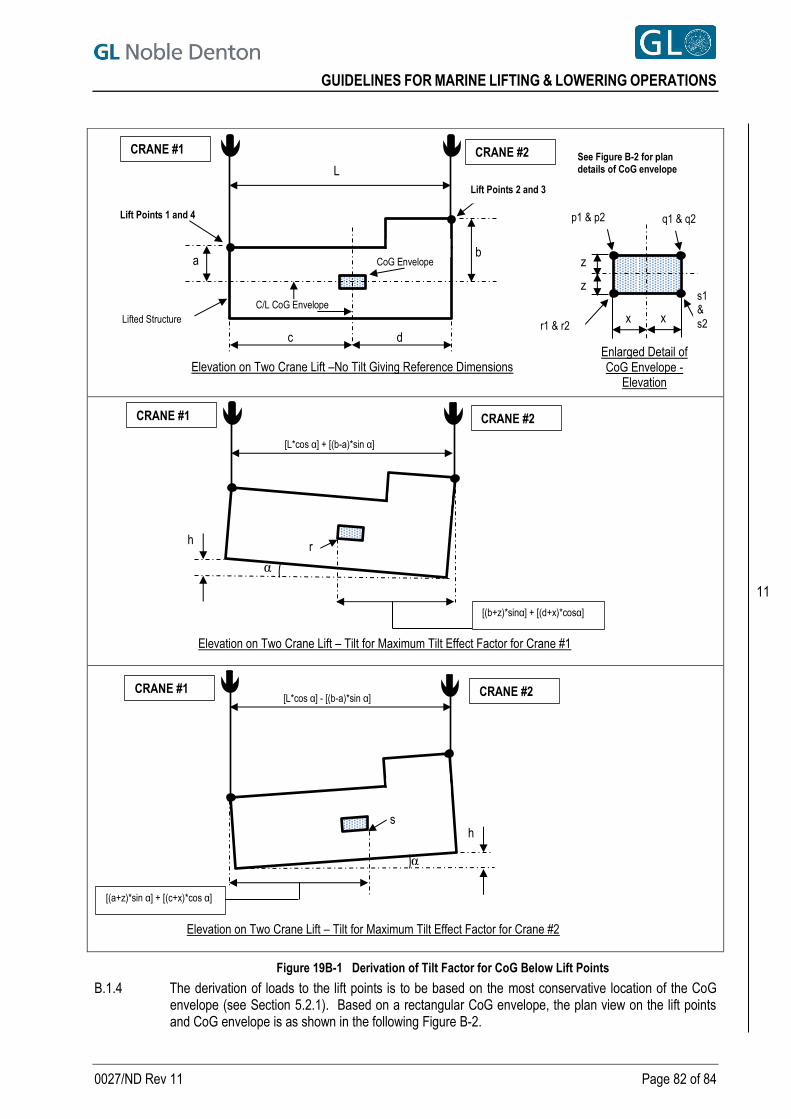
GUIDELINES FOR MARINE LIFTING & LOWERING OPERATIONS
0027/ND Rev 11 Page 82 of 84
B.1.4 The derivation of loads to the lift points is to be based on the most conservative location of the CoG envelope (see Section 5.2.1). Based on a rectangular CoG envelope, the plan view on the lift points and CoG envelope is as shown in the following Figure B-2.
Figure 19B-1 Derivation of Tilt Factor for CoG Below Lift Points
Elevation on Two Crane Lift – Tilt for Maximum Tilt Effect Factor for Crane #1
p1 & p2
x x
Enlarged Detail of CoG Envelope -
Elevation
z
z
C/L CoG Envelope
a b
q1 & q2
r1 & r2
s1 &
s2
c d
L
CRANE #1 CRANE #2
CoG Envelope
Lifted Structure
[L*cos α] + [(b-a)*sin α]
CRANE #1 CRANE #2
[(b+z)*sinα] + [(d+x)*cosα]
r h
α
[L*cos α] - [(b-a)*sin α] CRANE #1 CRANE #2
[(a+z)*sin α] + [(c+x)*cos α]
Elevation on Two Crane Lift – Tilt for Maximum Tilt Effect Factor for Crane #2
s
Elevation on Two Crane Lift –No Tilt Giving Reference Dimensions
h
α
Lift Points 1 and 4
Lift Points 2 and 3
See Figure B-2 for plan details of CoG envelope
11

GUIDELINES FOR MARINE LIFTING & LOWERING OPERATIONS
0027/ND Rev 11 Page 83 of 84
Figure B-2 Derivation of Lift Point Loads
For the condition of the CoG located below the lift points, see Section B.1.2, the load to the lift points, allowing for the tilt requirements given in Section B.1.2 are as follows:
For Crane #1, total load to lift point 1 = [(b+z)*sinα + (d+x)*cosα] * (f+y) * W [L*cosα + (b-a)*sinα] B
For Crane #1, total load to lift point 4 = [(b+z)*sinα + (d+x)*cosα] * (e+y) * W [L*cosα + (b-a)*sinα] B
For Crane #2, total load to lift point 2 = [(a+z)*sinα + (c+x)*cosα] * (f+y) * W [L*cosα - (b-a)*sinα] B
For Crane #2, total load to lift point 3 = [(a+z)*sinα + (c+x)*cosα] * (e+y) * W [L*cosα - (b-a)*sinα] B
The above formulae apply to the condition where the CoG is below the lift points. As referenced in Section B.1.3, if any part of the CoG is above the lowest lift point, the load derivation to the lift points under each crane will need to be assessed using the principles of Section B.1.2.
In Section B.1.2, an example was given to demonstrate the derivation of the total load to lift points 1 and 4 with a derivation showing the total load to lift points 2 and 3. As an example to demonstrate the derivation of lift points loads and using the same parameters for the elevation and weight properties given in Section B.1.2 (with the cranes on the same vessel and Section 5.4.2 applies) and the following plan details for the lifted structure (see Figure B-2):
Structure width, B, = 20.0m
CoG from lift points 1 and 2, e, = 11.0m
CoG from lift points 3 and 4, f, = 9.0m
CoG envelope size, y, horizontal = 0.6m
r1
x x
y
y
s1
r2 s2
Enlarged Detail of Bottom of CoG Envelope -
Plan
Plan on Two Crane Lift – No Tilt Giving Reference Dimensions
p1
x
y
y
q1
p2 q2 x
Enlarged Detail of Top of CoG Envelope -
Plan
For vertical details of CoG Envelope, refer to Figure 19B-1
Lift Point 1
Lift Point 4
Lift Point 2
Lift Point 3
L
c d
e
f
CENTRE LINE CRANE #1
CENTRE LINE CRANE #2
B
C/L CoG Envelope
CoG Envelope
11
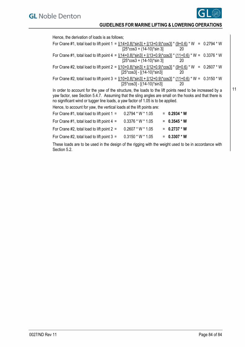
GUIDELINES FOR MARINE LIFTING & LOWERING OPERATIONS
0027/ND Rev 11 Page 84 of 84
Hence, the derivation of loads is as follows;
For Crane #1, total load to lift point 1 = [(14+0.8)*sin3] + [(13+0.9)*cos3] * (9+0.6) * W = 0.2794 * W [25*cos3 + (14-10)*sin 3] 20
For Crane #1, total load to lift point 4 = [(14+0.8)*sin3] + [(13+0.9)*cos3] * (11+0.6) * W = 0.3376 * W [25*cos3 + (14-10)*sin 3] 20
For Crane #2, total load to lift point 2 = [(10+0.8)*sin3] + [(12+0.9)*cos3] * (9+0.6) * W = 0.2607 * W [25*cos3] - [(14-10)*sin3] 20
For Crane #2, total load to lift point 3 = [(10+0.8)*sin3] + [(12+0.9)*cos3] * (11+0.6) * W = 0.3150 * W [25*cos3] - [(14-10)*sin3] 20
In order to account for the yaw of the structure, the loads to the lift points need to be increased by a yaw factor, see Section 5.4.7. Assuming that the sling angles are small on the hooks and that there is no significant wind or tugger line loads, a yaw factor of 1.05 is to be applied.
Hence, to account for yaw, the vertical loads at the lift points are:
For Crane #1, total load to lift point 1 = 0.2794 * W * 1.05 = 0.2934 * W
For Crane #1, total load to lift point 4 = 0.3376 * W * 1.05 = 0.3545 * W
For Crane #2, total load to lift point 2 = 0.2607 * W * 1.05 = 0.2737 * W
For Crane #2, total load to lift point 3 = 0.3150 * W * 1.05 = 0.3307 * W
These loads are to be used in the design of the rigging with the weight used to be in accordance with Section 5.2.
11