01-samss-017
DESCRIPTION
Auxiliary Piping for Mechanical EquipmentTRANSCRIPT

Previous Issue: 29 June 2005 Next Planned Update: 1 July 2010 Revised paragraphs are indicated in the right margin Page 1 of 13 Primar contact: Nasri, Nadhir Ibrahim on 966-3-8760162
Copyright©Saudi Aramco 2009. All rights reserved.
Materials System Specification
01-SAMSS-017 8 August 2009 Auxiliary Piping for Mechanical Equipment
Piping Standards Committee Members Nasri, Nadhir Ibrahim, Chairman Dib, Tony Georges, Vice Chairman Balhareth, Nasser Mohammad Bannai, Nabeel Saad Holland, Brad John Khashab, Jaafar M. Lewis, Trevor Mahmoud, Khalid Ahmed Phan, Howard Cong Rafie, Nader Yusof Rao, Sanyasi Rasheed, Mahmood A. Sharif, Talal Mahmoud Shiha, Saad Mohammed Swar, Ahmad H. (ABQ PLANTS)
Saudi Aramco DeskTop Standards Table of Contents 1 Scope............................................................ 2 2 Conflicts and Deviations............................... 2 3 References.................................................... 2 4 Definitions..................................................... 4 5 Responsibilities............................................. 4 6 Design Requirements................................... 5 7 Piping Materials and Components................ 6 8 Fabrication Requirements............................. 8 9 Inspection and Testing................................. 9 10 Cleaning....................................................... 10 11 Painting........................................................ 10 12 Preparation for Shipment............................. 10 Appendix A - Material Selection and Joining Methods....................................................... 12

Document Responsibility: Piping 01-SAMSS-017
Issue Date: 8 August 2009
Next Planned Update: 1 July 2010 Auxiliary Piping for Mechanical Equipment
Page 2 of 13
1 Scope
1.1 This specification defines the minimum mandatory requirements for the design,
fabrication, installation and inspection of auxiliary piping associated with
compressors, pumps, fans, turbines, engines and gears.
1.2 This specification is applicable for the services listed in Table-A-1 of Appendix-
A. To use this specification for services other than those in the Table-A-1, prior
approval from the Chairman of Piping Standards Committee shall be obtained in
writing.
2 Conflicts and Deviations
2.1 Any conflicts between this specification and other applicable Saudi Aramco
Materials System Specifications (SAMSSs), Engineering Standards (SAESs),
Standard Drawings (SASDs), or industry standards, codes, and forms shall be
resolved in writing by the Company or Buyer Representative through the
Manager, Consulting Services Department of Saudi Aramco, Dhahran.
2.2 Direct all requests to deviate from this specification in writing to the Company or
Buyer Representative, who shall follow internal company procedure SAEP-302
and forward such requests to the Manager, Consulting Services Department of
Saudi Aramco, Dhahran.
3 References
The selection of material and equipment, and the design, construction, maintenance, and
repair of equipment and facilities covered by this standard shall comply with the latest
edition of the references listed below, unless otherwise noted.
3.1 Saudi Aramco References
Saudi Aramco Engineering Procedure
SAEP-302 Instructions for Obtaining a Waiver of a
Mandatory Saudi Aramco Engineering
Requirement
Saudi Aramco Engineering Standard
SAES-H-101 Approved Protective Coating Systems
Saudi Aramco Materials System Specifications
32-SAMSS-013 Lubrication, Shaft Sealing and Control Oil
Systems for Special Purpose Applications

Document Responsibility: Piping 01-SAMSS-017
Issue Date: 8 August 2009
Next Planned Update: 1 July 2010 Auxiliary Piping for Mechanical Equipment
Page 3 of 13
Saudi Aramco Inspection Requirements
Form SA-175-019800 Auxiliary Piping
Saudi Aramco Standard Drawings
AB-036521 Standard Drawing Bridge Weld & Typical Brace
Seal Welded, and S.W. Valves on Process
Lines
3.2 Industry Codes and Standards
American Society of Mechanical Engineers
ASME B31.3 Process Piping
ASME B1.20.1 Pipe Threads, General Purpose (inch)
ASME B16.3 Malleable Iron Threaded Fittings
ASME B16.5 Pipe Flanges and Flanged Fittings
ASME B16.9 Wrought Butt Welding Fittings
ASME B16.11 Forged Steel Fittings, Socket-Welding and
Threaded
ASME B16.34 Steel Valves - Flanged, Threaded, and Welding
End
ASME BPVC SEC IX Welding and Brazing Qualifications
American Society for Testing and Materials
ASTM A53 Standard Specification for Pipe, Steel, Black and
Hot-dipped, Zinc-coated, Welded and Seamless
ASTM A105 Standard Specification for Carbon Steel Forgings
for Piping Applications
ASTM A106 Standard Specification for Seamless Carbon Steel
Pipe for High Temperature Service
ASTM A153 Standard Specification for Zinc Coating (Hot-Dip)
on Iron and Steel Hardware
ASTM A182 Standard Specification for Forged or Rolled
Alloy-Steel Pipe Flanges, Forged Fittings, and
Valves and Parts for High-Temperature Service
ASTM A197 Standard Specification for Cupola Malleable Iron

Document Responsibility: Piping 01-SAMSS-017
Issue Date: 8 August 2009
Next Planned Update: 1 July 2010 Auxiliary Piping for Mechanical Equipment
Page 4 of 13
ASTM A216 Standard Specification for Steel Castings, Carbon,
Suitable for Fusion Welding, for High
Temperature Service
ASTM A269 Standard Specification for Seamless and Welded
Austenitic Stainless Steel Tube
ASTM A276 Standard Specification for Stainless Steel Bars
and Shapes
ASTM A312 Standard Specification for Seamless and Welded
Austenitic Stainless Steel Pipes
ASTM A403 Standard Specification for Wrought Austenitic
Stainless Steel Piping Fittings
American Petroleum Institute
API STD 602 Compact Steel Gate Valves - Flanged, Threaded,
Welding, and Extended - Body Ends
National Association of Corrosion Engineers / International Standardization
Organization
NACE MR0175/ISO 15156 Petroleum and Natural Gas Industries-
Materials for use in H2S-Containing
Environments in Oil and Gas Production
4 Definitions
Auxiliary Piping: It is the piping connected to an equipment to support its function but
is not part of the main process lines, i.e., suction and discharge.
5 Responsibilities
Vendor Responsibilities:
5.1 The Vendor of the mechanical equipment shall be responsible for the design of
all auxiliary piping, within the scope of the purchasing contract.
5.2 Compliance with the provisions of this specification does not relieve the Vendor
from the responsibilities for furnishing equipment of proper design and quality
to meet the specified operating service conditions.
5.3 Drawings approved by the Buyer shall be limited to general design and principal
dimensions only and subject to corrections, if any, noted thereon. This approval
does not relieve the Vendor from responsibility for the adequacy and safety of
the equipment including the subject auxiliary piping. This approval shall not be

Document Responsibility: Piping 01-SAMSS-017
Issue Date: 8 August 2009
Next Planned Update: 1 July 2010 Auxiliary Piping for Mechanical Equipment
Page 5 of 13
construed as permission to deviate from the Purchase Order or this
Specification, unless specifically approved in writing by the Buyer.
6 Design Requirements
6.1 Sizes, materials, pressure ratings and types of all components shall be suitable
for the intended service. Design of auxiliary piping shall conform to ASME
B31.3 and shall be subject to approval by the Buyer when specified in the
Purchase Order.
6.2 The minimum size of auxiliary piping and tubing for mechanical equipment
shall be ½-inch NPS with the exception of air compressor packages which shall
be 3/8-inch NPS minimum.
6.3 All piping, tubing and valves shall be adequately supported and fastened in a
manner which facilitates replacement, prevents vibration, and damage due to
incidental loads which may occur during operation or maintenance work.
6.4 Piping of 1-½ inch NPS or smaller shall be provided with firm, welded gussets
or braces in two perpendicular planes at the take-off connection between the
machinery or auxiliary equipment and the first block (root) valve. Refer to
Standard Drawing AB-036521 for valve bracing.
Tubing shall be clipped with clamps.
6.5 Auxiliary piping shall be laid out to minimize interference with access to
components or appurtenances as required for routine operation and maintenance.
6.6 Flanged or union connections (where permitted per paragraph 7.4) shall be
provided closely to the equipment and throughout the piping system to permit
complete removal of the piping, and removal or assembly of the equipment.
6.7 All piping systems shall be provided with vent valves at highest points and drain
valves at lowest points. Horizontal runs in pressure piping shall slope gradually
towards drain points. The minimum slope of drain lines shall be 1:50.
Vents and drains shall be provided with circular plugs.
6.8 Pipe may be bent where necessary to achieve the desired configuration.
6.9 Miter fittings such as miter elbows or miter bends are prohibited.
6.10 Welded connections to vessels and lines shall be by means of forged steel
welding outlets (Threadolets or Sockolets or equal) and shall be class 3000 lb or
6000 lb to meet the pressure class.

Document Responsibility: Piping 01-SAMSS-017
Issue Date: 8 August 2009
Next Planned Update: 1 July 2010 Auxiliary Piping for Mechanical Equipment
Page 6 of 13
7 Piping Materials and Components
7.1 Material Selection and Joining Methods
7.1.1 Table A-1 in Appendix A, shows by means of an X the only permissible
materials and methods of joining of pipe, tubing and fittings for the listed
services.
7.1.2 Low temperature materials, when required, shall be suitable for the
intended service.
7.1.3 Materials in sour services shall be in accordance with NACE
MR0175/ISO 15156.
7.1.4 For sea water service, the material shall be stainless steel UNS S31254
welded with ERNiCrMo-3
7.2 Equivalent Materials
Items specified or referenced by brand names or proprietary names are not
intended to exclude equivalent items offered by other names. Products of
comparable type, quality and characteristics may be submitted for Buyer's
written acceptance with the Quotation.
7.3 Valves
7.3.1 End connections shall be in accordance with the permitted pipe joining
methods shown in Table-A-1.
7.3.2 Valves shall be in accordance with API STD 602 Class 800 or ASME
B16.34 with rating as required.
7.3.3 Valve materials shall be as required for the service but as a minimum
shall be forged or cast steel to ASTM A105 or A216 Grade WCB with
trim to 11-13% chrome AISI 410 stainless steel.
7.3.4 Valves shall have bolted bonnets and glands to be suitable for repacking
under pressure. Any deviation from this requirement must be reviewed
and approved by the Chairman of Valves Standards Committee in
Consulting Services Department.
7.3.5 For throttling service, globe or needle valves shall be used.
7.3.6 A block valve, 3/4-inch NPS minimum, shall be installed in each
instrument take-off connection from the main lines and shall be located
as close as feasible to this main line, vessel, or mechanical equipment.

Document Responsibility: Piping 01-SAMSS-017
Issue Date: 8 August 2009
Next Planned Update: 1 July 2010 Auxiliary Piping for Mechanical Equipment
Page 7 of 13
Exception:
Thermocouples and thermometers are excluded from the ¾-inch NPS minimum requirement.
7.3.7 Instrument valves serving protected instrument areas such as panels and
gauge boards may be ½-inch instrument type valves.
7.3.8 Check valves used to retain pressure in the pressurized dual mechanical
seals of centrifugal pumps in idle condition shall be of the non-slam,
tight shut-off design.
7.4 Unions
7.4.1 Unions are not permitted in pressurized lines carrying flammable or toxic
fluids except when they are required for removal or assembly of the
equipment and cannot otherwise be substituted by flanges.
7.4.2 Use of any unions requires approval from the Chairman of Piping
Standards Committee, Consulting Services Department.
7.4.3 Under any circumstances, unions shall not be installed in the pipe section
between the pipe run and the root valve.
7.5 Tubing
7.5.1 Tubing may be used instead of pipe beyond the first valve in a line where
socket welded or threaded connections are normally permitted.
7.5.2 The maximum allowable pressure and temperature limits for tubing are
3400 kPa (500 psig) and 120°C.
7.5.3 Minimum wall thickness for ½, ¾ and 1-inch tubing are 1.6, 2.4 and
2.8 mm respectively.
7.6 Fittings and Flanges
7.6.1 Fittings and flanges shall conform to the following Standards and
Specifications:
a) Malleable iron threaded fittings, ASME B16.3 Class 150 with
material to ASTM A197, hot dip galvanized to ASTM A153.
b) Flanges, carbon steel to ASME B16.5 and stainless steel to ASTM
A182 Grade TP-316L.
c) Butt welding fittings to ASME B16.9. Stainless steel to ASTM
A403 Grade WP-316L.

Document Responsibility: Piping 01-SAMSS-017
Issue Date: 8 August 2009
Next Planned Update: 1 July 2010 Auxiliary Piping for Mechanical Equipment
Page 8 of 13
d) Socket welding and threaded fittings shall be ASME B16.11 class
3000 or class 6000 Carbon steel to ASTM A105 N and stainless
steel to ASTM A182 Grades F-304L or F-316L.
7.6.2 Flanges mating to cast iron flanges shall be flat faced.
7.6.3 Gaskets for raised flanges shall be spiral-wound, Type 316 stainless
steel. Gaskets for ring joint flanges shall be soft iron octagonal ring.
Gaskets containing asbestos are not permitted.
7.7 Piping Joints
7.7.1 Threaded connections shall be held to a minimum and shall be seal
welded (except for instruments and mechanical seal gland connections)
for the following:
General hydrocarbon
Other flammable fluids under pressure
Hazardous or toxic fluids
Steam at pressures over 1700 kPa (250 psig) or temperatures over
210ºC.
7.7.2 Threaded joints that are to be seal welded shall be fitted dry without the
use of thread compound or Teflon tape. Pipe bushings shall not be used.
7.7.3 Threaded connections shall conform to ASME B1.20.1 Pipe Threads.
7.8 Tubing Joints
For tubing, connectors and adapters shall be compression type meeting
UNS S-31600 and ASTM A276.
8 Fabrication Requirements
8.1 Bolt holes of flanges shall straddle the vertical and horizontal center lines.
8.2 Pipe bends shall have surfaces free of cracks and buckles. Flattening of the
cross section of bends shall not exceed 8 percent of the nominal pipe diameter.
Bending procedures and heat treatment requirements shall be in accordance with
ASME B31.3.
8.3 Welding
8.3.1 Welding procedures and welders shall be qualified in accordance with
the provisions of ASME SEC IX of the Boiler and Pressure Vessel Code.
Document Responsibility: Piping 01-SAMSS-017
Issue Date: 8 August 2009
Next Planned Update: 1 July 2010 Auxiliary Piping for Mechanical Equipment
Page 9 of 13
All welding procedures and welding performance qualification records
shall be made available to Buyer's Inspector for review.
8.3.2 Where pipe, fittings and flanges are to be joined by butt welds, the
corresponding parts shall be matched such that any misalignment at the
inside of the piping shall not exceed 1.5 mm at any point on the
circumference of the joint.
8.3.3 All welds must meet the minimum quality requirements of ASME B31.3
together with the following additional requirements:
a) For pipe sizes 2 inch and smaller the first pass of butt welded joints
shall be made with Gas Tungsten Arc Welding (GTAW) process.
b) Permanent backing rings are prohibited, but consumable inserts of
the same chemistry as the remaining weld metal may be used.
8.3.4 Seal welds on threaded connections shall cover all exposed threads after
the joint has been tightened to full thread engagement. The fillet seal
weld shall have a minimum throat thickness of 3 mm and shall merge
smoothly into the pipe metal outside of the thread. Threaded joints to be
seal welded shall be fully cleaned and made up dry without joint
compounds or PTFE (Teflon) tape.
8.3.5 Dissimilar metal welds between ferritic steel and either austenitic
stainless steel, duplex stainless steel, or nickel-based alloys as well as
use of stainless steel or nickel-based filler metals on ferritic steel are not
permitted for pressure containing welds in sour service.
8.3.6 Brackets and supports welded on the mechanical equipment or on the
baseplate shall have full length welds. Intermittent welding is
prohibited. Brackets material shall be selected to prevent galvanic
corrosion.
8.4 Threaded connection with seal weld, or socket weld is allowed only for the first
connection with the mechanical seal cover plate.
9 Inspection and Testing
9.1 The auxiliary piping is subject to verification per Form SA-175-019800 attached
to the Purchase Order.
9.2 All tests and inspections shall be carried out at the equipment Vendor's plant or
at the sub-vendor's plant.
9.3 Radiographic Requirements

Document Responsibility: Piping 01-SAMSS-017
Issue Date: 8 August 2009
Next Planned Update: 1 July 2010 Auxiliary Piping for Mechanical Equipment
Page 10 of 13
Butt-welds in auxiliary piping shall be subjected to 10 percent random
radiographic examination (i.e. one complete girth weld from every 10 girth
welds as selected by Buyer's Inspector). However, a minimum of two girth
welds shall be radio graphed, regardless of the lot size. One hundred percent
radiography is required for auxiliary piping in hydrocarbon service on offshore
platforms.
9.4 Hydrostatic testing with water or light oil is required for all fabricated piping
assemblies. Test pressures shall be in accordance with ASME B31.3 and shall
be indicated on the Vendor's Piping Drawings.
10 Cleaning
In addition to the requirements per 32-SAMSS-013, the following requirements shall be
met.
10.1 Shop fabricated piping shall be cleaned internally prior to installing on the
mechanical equipment and prior to mechanical or performance testing.
10.2 Stainless steel lube oil and seal oil piping downstream of the filter shall be
mechanically cleaned at welds to the extent that all foreign materials are
removed. All other piping shall be cleaned by steam, air or water flushing and if
necessary by mechanical cleaning.
10.3 All piping shall be completely drained and dried.
10.4 All carbon steel piping shall be flushed with a rust preventative prior to
shipment when specified in the Purchase Order.
11 Painting
The exterior of all carbon steel piping components shall be supplied with a protective
coating as specified in SAES-H-001 and SAES-H-101. Threads and open ends
prepared for field welding and connecting shall not be painted.
12 Preparation for Shipment
12.1 All open ends of piping, whether installed on the mechanical equipment or
shipped separately, shall be plugged or blanked properly. Threaded connections
shall be protected with a plastic or steel threaded plug for the female end and a
thread protector for the male end. Wooden plugs are not permitted to be used
for this purpose.
12.2 Loose piping components shall be properly identified with tags prior to crating
or boxing. If size permits, components may be marked with paint. The marking

Document Responsibility: Piping 01-SAMSS-017
Issue Date: 8 August 2009
Next Planned Update: 1 July 2010 Auxiliary Piping for Mechanical Equipment
Page 11 of 13
shall include: Service, item equipment number and any mark number shown on
the piping drawings.
12.3 Auxiliary piping and tubing installed on mechanical equipment shall be properly
protected against impact damage during transportation.
12.4 Piping which cannot be installed on the mechanical equipment during transport
for reasons of space or risk of damage shall be packed in a wooden box or crate
and shall be shipped together with the mechanical equipment.
Revision Summary
29 June 2005 Major revision. 8 August 2009 Editorial revision to replace cancelled SAES-A-301 with NACE MR0175/ISO 15156.
Document Responsibility: Piping 01-SAMSS-017
Issue Date: 8 August 2009
Next Planned Update: 1 July 2010 Auxiliary Piping for Mechanical Equipment
Page 12 of 13
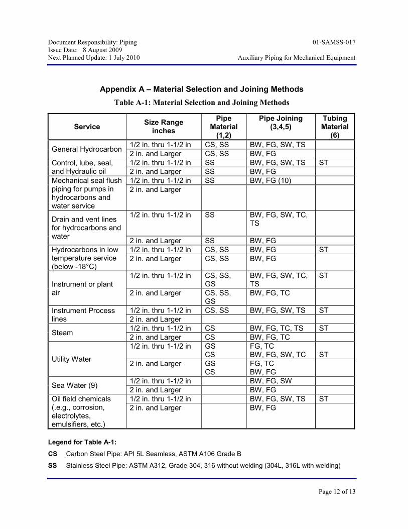
Appendix A – Material Selection and Joining Methods
Table A-1: Material Selection and Joining Methods
Service
Size Range inches
Pipe Material
(1,2)
Pipe Joining (3,4,5)
Tubing Material
(6)
General Hydrocarbon 1/2 in. thru 1-1/2 in CS, SS BW, FG, SW, TS
2 in. and Larger CS, SS BW, FG
Control, lube, seal, and Hydraulic oil
1/2 in. thru 1-1/2 in SS BW, FG, SW, TS ST
2 in. and Larger SS BW, FG
Mechanical seal flush piping for pumps in hydrocarbons and water service
1/2 in. thru 1-1/2 in SS BW, FG (10)
2 in. and Larger
Drain and vent lines for hydrocarbons and water
1/2 in. thru 1-1/2 in SS
BW, FG, SW, TC, TS
2 in. and Larger SS BW, FG
Hydrocarbons in low temperature service (below -18°C)
1/2 in. thru 1-1/2 in CS, SS BW, FG ST
2 in. and Larger CS, SS BW, FG
Instrument or plant air
1/2 in. thru 1-1/2 in CS, SS, GS
BW, FG, SW, TC, TS
ST
2 in. and Larger CS, SS, GS
BW, FG, TC
Instrument Process lines
1/2 in. thru 1-1/2 in CS, SS BW, FG, SW, TS ST
2 in. and Larger
Steam 1/2 in. thru 1-1/2 in CS BW, FG, TC, TS ST
2 in. and Larger CS BW, FG, TC
Utility Water
1/2 in. thru 1-1/2 in GS CS
FG, TC BW, FG, SW, TC
ST
2 in. and Larger GS CS
FG, TC BW, FG
Sea Water (9) 1/2 in. thru 1-1/2 in BW, FG, SW
2 in. and Larger BW, FG
Oil field chemicals (.e.g., corrosion, electrolytes, emulsifiers, etc.)
1/2 in. thru 1-1/2 in BW, FG, SW, TS ST
2 in. and Larger BW, FG
Legend for Table A-1:
CS Carbon Steel Pipe: API 5L Seamless, ASTM A106 Grade B
SS Stainless Steel Pipe: ASTM A312, Grade 304, 316 without welding (304L, 316L with welding)

Document Responsibility: Piping 01-SAMSS-017
Issue Date: 8 August 2009
Next Planned Update: 1 July 2010 Auxiliary Piping for Mechanical Equipment
Page 13 of 13
GS Galvanized Steel Pipe: ASTM A53 or API Grade B
BW Buttwelded
FG Flanged
SW Socket Welded
TC Threaded and Coupled
TS Threaded and Coupled, Seal Welded
ST Stainless Steel Tube: ASTM A269; TP-316 without welding (TP-316L with welding)
Notes to Table A-1:
1) The minimum wall thickness of piping and butt welding fittings shall be Schedule 40 for sizes larger than 2-inch and Schedule 80 for sizes 2-inch and smaller. For lube oil service, schedule 10S is acceptable for sizes 2-inch and larger.
2) Galvanized steel pipe and malleable iron fittings are limited to temperatures between 0 and 90°C and sizes 2-inch and smaller.
3) Flanges, socket welding and threaded fittings shall be the class, rating or wall thickness to match the pipe ratings. Galvanized steel pipe Schedule 40 and malleable iron fittings shall be Class 150.
4) The material of the first threaded nipple to mechanical equipment shall be compatible with the material of the equipment and the thickness shall be minimum of schedule 80. Socket welding and threaded joints are limited to sizes 1-½-inch and smaller.
5) Socket welded or threaded fittings may be used where indicated for temperatures between -18 and 400°C. Above 400°C flanged connections are required.
Socket welded end connections shall take preference over threaded and seal welded connections.
6) Tubing may be used instead of pipe beyond the first valve in a line where socket welded or threaded connections are normally permitted.