01 the parameters optimization of the servosystem based on
TRANSCRIPT

Qi Hao*, Zhankui Qiu, Xiaowei Wang, Antong Gao
*Institute of Army Aviation, Beijing 101123, China [email protected]
Keywords: Control parameter optimization; the genetic algorithm method; servosystem control; PID control algorithm.
Abstract
The control parameters optimization of the servosystem in parallel robots, which is the basis of the control system design of the robot, is very important. In this paper, the parameters optimization of the servosystem based on the genetic algorithm method is introduced. In the servosystem of parallel robots, a three-closed-loop PID control method is usually used. So the control parameters of the speed control loop and position control loop of the servosystem have great influence on the performance of the motor. To meet the requirement of the control system, a three-closed-loop PID control structure of the servosystem is designed according to the hardware system of the AC servo. With the time-domain performance and dynamic characteristic as the optimization targets, the control parameters of the speed control loop and position control loop are optimized. Comparing with the tuning result optimized by the traditional Ziegler-Nichols tuning laws, the results obtained by the GA method show better performance in the computer simulation of a parallel robot. Therefore, the GA method which is used in the optimization of the control parameters of the servosystem, has the advantages of simple calculation, fast tuning speed, good optimization result, and so on.
1 Introduction
PID control method is one of the earliest developed control strategies [1]. Because of its simple principle, easy application and strong robustness, PID control method is applied in various industrial processes. As one of the most widely used control methods, it has not been eliminated due to the emergence of various advanced control algorithms. On the contrary, this method still has a strong vitality in modern industrial production, because of its irreplaceable advantages and rich experience. In practical application of the PID method, different choices of the three control parameters Kp, Ti and Td affect the control performance. These years, engineers have accumulated a wealth experience of the PID parameter tuning.
In 1942, Ziegler and Nichols [2] proposed a new empirical formula, named Ziegler-Nichols tuning rule, which is famous in the parameter tuning of the PID controller. In 1991, Hang [3] proposed an accurately adjusted Ziegler-Nichols tuning rule. In 1993, based on error integral index, Zhuang and Atherton [4] put forward a parameter optimization method of the PID controller. In 1999, O 'Dwyer [5, 6] listed hundreds of parameter tuning methods based on a FOLPD (first order lag and plus delay) model and a FOLIPD (first order lag and integrator plus delay) model. For the complex control system in modern industrial production, the setting of control parameters of the servosystem is more complex. The parameter turning rely on experience is not able to meet the design requirements. In recent years, some scholars put forward parameter tuning methods of the PID controller based on some mechanism or some control method [7]. Other scholars proposed parameter tuning methods based on a modern intelligent algorithm [8]. In 2007, Wang [9] optimized the control parameters of a PID controller used in the speed regulation system of a diesel engine.
2 Mathematical model of motor servo control system
As shown in fig. 1, the motor and the slider are the control objects of the servosystem. According to the physical law of the servo motor, the mathematical model of the controlled motor can be written as:
i a
d
d
i tu t Ri t L e t
t (1)
tT t K i t (2)
oa e
d
d
te t K
t
(3)
2o o
c 2
d d
d d
t tT t M t f J
t t
(4)
Where, iu t is the input voltage of the motor armature,
i t is the current through the armature winding, ae t is the
counter electromotive force of the armature, T t is the motor
Optimization Of The Control Parameters Of A Servosystem Based On The Genetic Algorithm Method
2nd Joint International Information Technology, Mechanical and Electronic Engineering Conference (JIMEC 2017)
Copyright © 2017, the Authors. Published by Atlantis Press. This is an open access article under the CC BY-NC license (http://creativecommons.org/licenses/by-nc/4.0/).
Advances in Computer Science Research, volume 62
534
output torque, o t is the motor output angle, f is the
friction coefficient by load torque, motor, roller screw and load equivalent.
o
Fig 1: The mathematical model of the motor servo control
system The other parameters of the PID control system are shown in Table 1. Parameter Comment Value Unit
Kpp The proportion coefficient of
the position loop Undeter-
mined s-1
Tip The integral time constant of
the position loop undeter-mined
s
Tdp The differential time
constant of the position loop Undeter-
mined s
Kpv The proportion coefficient of
the velocity loop Undeter-
mined N m mi
Tiv The integral time constant of
the velocity loop Undeter-
mined s
Kpi The proportion coefficient of
the current loop 84
1V A
Tii The integral time constant of
the current loop 0.001 35 s
Kt The motor torque constant 1.09 N m A
Ke The back EMF constant 0.63 V s rad
L The motor winding
inductance 0.012 H
R The motor winding
resistance 8.65 Ohm
J The inertia of the motor and
lead screw 0.08 kg m2
Table 1: The control parameters of the motor servosystem As shown in Eq. (1) to Eq. (4), the Laplace change of the mathematical model of motor control system can be written as
t i co 3 2 3 2
e t e t
( ) ( ) ( )( )
K U s R Ls M ss
LJs RJs K K s LJs RJs K K s
(5)
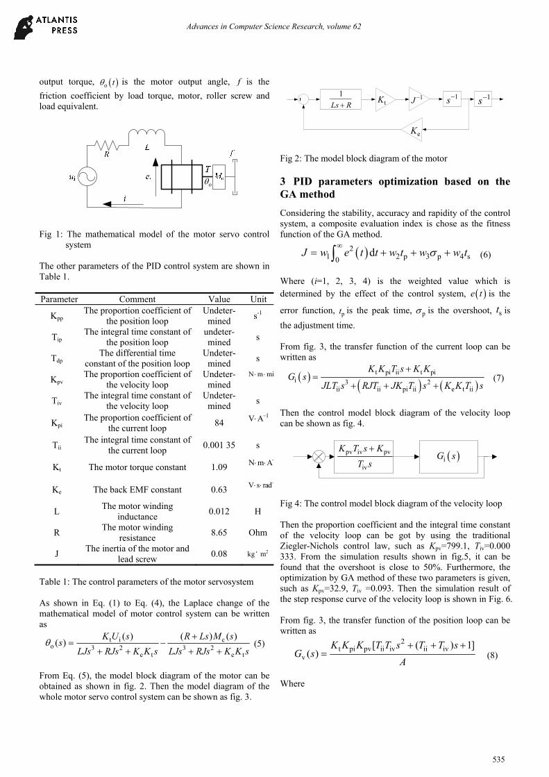
From Eq. (5), the model block diagram of the motor can be obtained as shown in fig. 2. Then the model diagram of the whole motor servo control system can be shown as fig. 3.
1
Ls R tK 1J 1s 1s
eK
Fig 2: The model block diagram of the motor
3 PID parameters optimization based on the GA method
Considering the stability, accuracy and rapidity of the control system, a composite evaluation index is chose as the fitness function of the GA method.
21 2 p 3 p 4 s0
dJ w e t t w t w w t
(6)
Where (i=1, 2, 3, 4) is the weighted value which is determined by the effect of the control system, e t is the
error function, pt is the peak time, p is the overshoot, st is
the adjustment time. From fig. 3, the transfer function of the current loop can be written as
t pi ii t pi
i 3 2ii ii pi ii e t ii
K K T s K KG s
JLT s RJT JK T s K K T s
(7)
Then the control model block diagram of the velocity loop can be shown as fig. 4.
pv iv pv
iv
K T s K
T s
iG s
Fig 4: The control model block diagram of the velocity loop Then the proportion coefficient and the integral time constant of the velocity loop can be got by using the traditional Ziegler-Nichols control law, such as Kpv=799.1, Tiv=0.000 333. From the simulation results shown in fig.5, it can be found that the overshoot is close to 50%. Furthermore, the optimization by GA method of these two parameters is given, such as Kpv=32.9, Tiv =0.093. Then the simulation result of the step response curve of the velocity loop is shown in Fig. 6. From fig. 3, the transfer function of the position loop can be written as
2t pi pv ii iv ii iv
v
[ ( ) 1]( )
K K K T T s T T sG s
A
(8)
Where
Advances in Computer Science Research, volume 62
535

4 3ii iv pi ii iv pi iv
2t e ii iv t pi pv ii iv
t pi pv ii iv t pi pv
( ) (
)
( )
A JLT T s J R K T T s JK T
K K T T K K K T T s
K K K T T s K K K
Fig 5: The step response curve of the velocity loop after the
tuning of Ziegler-Nichols law
Fig 6: The step response curve of the velocity loop after the
optimization of the GA method Then the control model block diagram of the position loop can be shown as fig. 7.
2pp ip dp pp iv pp
ip
K T T s K T s K
T s
vG s
Fig 7: The control model block diagram of the position loop By the Ziegler-Nichols rule, the PID parameters of the position control loop are Kpp=19.2, Tpi=0.000 1, Tpv=0.000 025. From the simulation result of the position control loop as shown in fig. 8, it can be found that, the control system has a large overshoot shock and long adjustment time. Then, the optimization by GA method of these three parameters is given, such as Kpp=8.42,Tpi=0.40,Tpd=0.05. Then the simulation of the position loop is shown in fig. 9.
Fig 8. The step response curve of the position loop after the
tuning of Ziegler-Nichols law
Fig 9. The step response curve of the position loop after the
optimization of the GA method
4 The control simulation experiment of a parallel robot
The tuning results of the speed control loop and the position control loop of the parallel robot servo system are obtained through the optimization of the previous sections. Further, the above parameters are added to the motion control model of the parallel machine tool, and the numerical simulation of the actual control effect of the machine tool is carried out in order to gain a more comprehensive understanding of the control effect of the optimized parameters. In the process of simulation, the moving platform is simulated with a high speed, which is a circular arc trajectory simulation. The simulation results are shown in fig. 10 and fig. 11. The simulation results shown in fig. 10 and fig. 11 show that the parameters of the position controller and speed controller obtained by genetic algorithm can meet the requirements of the high-speed operation of the parallel machine tool. Considering the dynamic characteristics of the parallel machine tool at high speed and the limitation of the PID control, the tracking error is very satisfactory. Therefore, the genetic algorithm is added to the PID parameter tuning, which is not only fast, but also ideal.
Advances in Computer Science Research, volume 62
536

Fig 10. The simulation of circular arc motion of the parallel
robot
Fig 11. The tracking error of circular arc motion of the
parallel robot
5 Conclusions
From the simulation results, it can be found that the PID control parameter optimization method based on GA has high efficiency, setting the optimization results to the advantages. For high-speed parallel robot, the control system often uses
the traditional PID control. So the choice of the PID control parameters affects the upper dynamic control system. The PID control parameter optimization based on GA method can meet the requirements of the control system of the modern industrial equipment. Acknowledgment
Acknowledgements
This work is supported by the National Nature Science Foundation of China (Grant No. 51405509), all support is gratefully acknowledged.
References
[1] Bennett S. Development of the PID controllers. IEEE Control Systems Magazine, 13 (6), pp. 58-65, (1993).
[2] Ziegler J G, Nichols N B. Optimum setting for automatic controllers. Transaction of ASME, 64, pp. 759-768, (1944).
[3] Hang C C, Astrom K J, Ho W K. Refinement of the Ziegler-Nichols tuning formula. IEE Proceeding-D Control Theory and Applications, 138(2), pp. 111-118, (1991).
[4] Zhuang M, Atherton D P. Automatic turning of optimum PID controllers. IEE Proceeding-D Control Theory and Applications, 140(3), pp. 216-224, (1993).
[5] O’Dwyer A. A summary of PI and PID controller tuning rules for processes with time delay. Part 1: PI controller tuning rules. Proceedings of PID ’00: IFAC Workshop on Digital Control. Terrassa, 4, pp. 175-180 , (2000).
[6] O’Dwyer A. Handbook of PI and PID Controller Tuning Rules. Imperial College Press, London, (2003).
[7] Yang Z Y, Huang T, Mei J P, et al. Whole workspace optimization based parameter tuning of high-speed parallel manipulator controller. Chinese Journal of Mechanical Engineering, 42(9), pp. 123-129, (2006).
[8] WANG Ling, TANG Fang. Study on PID tuning based on genetic annealing strategy [J]. Control and Instruments in Chemical Industry, 29(3), pp. 21-24, (2002).
[9] Wang H, Li M H. GA-based PID tuning of the diesel speed-reulating system. Techniques of Automation & Applications, 26(5), pp. 19-22, (2007).
1
Ls R tK 1J 1s 1s
eK
2pp ip dp pp ip pp
1
K T T s K T s K
Ns
pv iv pv
iv
K T s K
T s
pi ii pi
ii
K T s K
T s
Fig 3: The model diagram of the whole motor servo control system
Advances in Computer Science Research, volume 62
537