01e35_1
DESCRIPTION
01E35_1TRANSCRIPT

68P80801E35-OECCN 5E992
Network Solutions Sector
ENHANCED BASE TRANSCEIVER SYSTEM (EBTS)
VOLUME 1 OF 3SYSTEM INSTALLATION AND TESTING
© 2001 Motorola, Inc.All Rights ReservedPrinted in U.S.A.

FCC INTERFERENCE WARNING
The FCC requires that manuals pertaining to Class A computing devices must contain warnings about possible interference with local residential radio and TV reception. This warning reads as follows:
Note: This equipment has been tested and found to comply with the limits for a Class A digital device, pursuant to Part 15 of the FCC Rules. These limits are designed to provide reasonable protection against harmful interference when the equipment generates, uses, and can radiate radio frequency energy and, if not installed and used in accordance with the instruction manual, may cause harmful interference to radio communications. Operation of this equipment in a residential area is likely to cause harmful interference in which case the user will be required to correct the interference at his own expense.
INDUSTRY OF CANADA NOTICE OF COMPLIANCE
This Class A digital apparatus meets all requirements of the Canadian Interference-Causing Equipment Regulations. Cet appareil numérique de la classe A respecte toutes les exigences du Règlement sur le matériel brouilleur du Canada.
COMMERCIAL WARRANTY (STANDARD)
Motorola radio communications products (the “Product”) is warranted to be free from defects in material and workmanship for a period of ONE (1) YEAR (except for crystals and channel elements which are warranted for a period of ten (10 years) from the date of shipment. Parts including crystals and channel elements, will be replaced free of charge for the full warranty period but the labor to replace defective parts will only be provided for One Hundred-Twenty (120) days from the date of shipment. Thereafter purchaser must pay for the labor involved in repairing the Product or replacing the parts at the prevailing rates together with any transportation charges to or from the place where warranty service is provided. This express warranty is extended by Motorola, 1301 E. Algonquin Road, Schaumburg, Illinois 60196 to the original end use purchaser only, and only to those purchasing for purpose of leasing or solely for commercial, industrial, or governmental use.
THIS WARRANTY IS GIVEN IN LIEU OF ALL OTHER WARRANTIES EXPRESS OR IMPLIED WHICH ARE SPECIFICALLY EXCLUDED, INCLUDING WARRANTIES OF MERCHANTABILITY OR FITNESS FOR A PARTICULAR PURPOSE. IN NO EVENT SHALL MOTOROLA BE LIABLE FOR INCIDENTAL OR CONSEQUENTIAL DAMAGES TO THE FULL EXTENT SUCH MAY BE DISCLAIMED BY LAW.
In the event of a defect, malfunction or failure to conform to specifications established by Motorola, or if appropriate to specifications accepted by Motorola in writing, during the period shown, Motorola, at its option, will either repair or replace the product or refund the purchase price thereof. Repair at Motorola's option, may include the replacement of parts or boards with functionally equivalent reconditioned or new parts or boards. Replaced parts or boards are warranted for the balance of the original applicable warranty period. All replaced parts or product shall become the property of Motorola.
This express commercial warranty is extended by Motorola to the original end user purchaser or lessee only and is not assignable or transferable to any other party. This is the complete warranty for the Product manufactured by Motorola. Motorola assume no obligations or liability for additions or modifications to this warranty unless made in writing and signed by an officer of Motorola. Unless made in a separate agreement between Motorola and the original end user purchaser, Motorola does not warrant the installation, maintenance or service of the Products.
Motorola cannot be responsible in any way for any ancillary equipment not furnished by Motorola which is attached to or used in connection with the Product, or for operation of the Product with any ancillary equipment, and all such equipment is expressly excluded from this warranty. Because each system which may use Product is unique, Motorola disclaims liability for range, coverage, or operation of the system as a whole under this warranty.
This warranty does not cover:
a) Defects or damage resulting from use of the Product in other than its normal and customary manner.
b) Defects or damage from misuse, accident, water or neglect
c) Defects or damage from improper testing, operation, maintenance installation, alteration, modification, or adjusting.
d) Breakage or damage to antennas unless caused directly by defects in material workmanship.
e) A Product subjected to unauthorized Product modifications, disassemblies or repairs (including without limitation, the addition to the Product of non-Motorola supplied equipment) which adversely affect performance of the Product or interfere with Motorola's normal warranty inspection and testing of the Product to verify any warranty claim.
f) Product which has had the serial number removed or made illegible.
g) A Product which, due to illegal to unauthorized alteration of the software/firmware in the Product, does not function in accordance with Motorola's published specifications or the FCC type acceptance labeling in effect for the Product at the time the Product was initially distributed from Motorola.
This warranty sets forth the full extent of Motorola's responsibilities regarding the Product. Repair, replacement or refund of the purchase date, at Motorola’s option is the exclusive remedy. IN NO EVENT SHALL MOTOROLA BE LIABLE FOR DAMAGES IN EXCESS OF THE PURCHASE PRICE OF THE PRODUCT, FOR ANY LOSS OF USE, LOSS OR TIME, INCONVENIENCE, COMMERCIAL LOSS, LOST PROFITS OR SAVINGS OR OTHER INCIDENTAL, SPECIAL OR CONSEQUENTIAL DAMAGE ARISING OUT OF THE USE OR INABILITY TO USE SUCH PRODUCT, TO THE FULL EXTENT SUCH MAY BE DISCLAIMED BY LAW.
SOFTWARE NOTICE/WARRANTY
Laws in the United States and other countries preserve for Motorola certain exclusive rights for copyrighted Motorola software such as the exclusive rights to reproduce in copies and distribute copies of such Motorola software. Motorola software may be used in only the Product in which the software was originally embodied and such software in such Product may not be replaced, copied, distributed, modified in any way, or used to produce any derivative thereof. No other use including without limitation alteration, modification, reproduction, distribution, or reverse engineering of such Motorola software or exercise of rights in such Motorola software is permitted. No license is granted by implication, estoppel or otherwise under Motorola patent rights or copyrights.
This warranty extends only to individual products: batteries are excluded, but carry their own separate limited warranty.
In order to obtain performance of this warranty, purchaser must contact its Motorola salesperson or Motorola at the address first above shown, attention Quality Assurance Department.
This warranty applies only within the fifty (50) United States and the District of Columbia.

1 Contents
Contents
Foreword...................................................................................................................................x
Reference Materials (MSER) ................................................................................................. xi
Available Field Replaceable Units ....................................................................................... xiii
General Safety Information ................................................................................................. xvii
System Description 68P81086E74
EBTS Site Description .............................................................................................................2
EBTS Overall Functional Description .....................................................................................3
EBTS Cabinet Configurations .................................................................................................6
EBTS Component Descriptions ...............................................................................................9
EBTS Configuration Descriptions..........................................................................................20
Pre-Installation 68P81094E79
Site Planning.............................................................................................................................2
Receipt of Equipment .............................................................................................................11
Electrical Requirements..........................................................................................................13
Grounding Requirements........................................................................................................18
Antenna Installation ...............................................................................................................24
Alarm Wiring..........................................................................................................................30
Recommended Tools, Equipment, and Parts ..........................................................................31
Installation 68P81094E94
Introduction...............................................................................................................................2
EBTS Cabinet Installation ........................................................................................................5
Power Supply Rack Installation................................................................................................8
Cabinet And Site Connections..................................................................................................9
Intercabinet Cabling Procedures.............................................................................................13
Cabinet-to-Site Cabling Procedures .......................................................................................38
Final Checkout 68P81094E96
Checkout Procedures Required Based On System Configuration............................................2
Final Checkout Setup................................................................................................................3
Powering the Power Supply System.........................................................................................6
Applying Power to the Equipment Cabinets ..........................................................................14
Applying Power to Components Within Equipment Cabinets ...............................................16
68P80801E35-O 4/1/2001 iiiNetwork Solutions Sector
1301 E. Algonquin Road, Schaumburg, IL 60196
Contents EBTS System Manual - Vol 1
System Testing 68P81094E97
Testing Overview..................................................................................................................... 2
Site Control Verification.......................................................................................................... 3
RF Cabinet Verification .......................................................................................................... 4
System Troubleshooting 68P81094E98
Troubleshooting ...................................................................................................................... 2
Base Radio Fault Indications/Isolation.................................................................................... 3
Excessive BER Fault Isolation ................................................................................................ 8
RF Distribution System Fault Isolation ................................................................................. 15
Miscellaneous Troubleshooting ............................................................................................ 18
Software Commands 68P81094E99
MMI Commands...................................................................................................................... 2
Base Radio Commands............................................................................................................ 4
Generation 3 Site Controller (Gen 3 SC) 68P81095E01
Controller................................................................................................................................. 2
Acronyms 68P81095E06
Parts and Suppliers 68P81095E07
Optional High Precision Receiver BER Testing 68P81095E67
Required Test Equipment and Shop Fixture Setup.............................................................C - 2
Test Equipment Setup and Calibration Procedures ............................................................C - 4
BER Sensitivity Test Procedure .......................................................................................C - 14
Index 68P81095E69
iv 68P80801E35-O 4/1/2001
EBTS System Installation and Testing Contents
List of Tables
Pre-Installation 68P81094E79
Table 1 Cabinet and Rack Dimensions .......................................................................................................... 3
Table 2 Equipment Cabinet Weight and Floor Loading ................................................................................ 5
Table 3 Power Supply Rack Weight and Floor Loading ............................................................................... 7
Table 4 Battery Rack Weight and Floor Loading .......................................................................................... 7
Table 5 Typical AC Power Loads (Imposed by DC Power System) (70 W BR) ........................................ 14
Table 6 Recommended Power Panel Layout ............................................................................................... 15
Table 7 48VDC Power Bus Color Coding................................................................................................... 16
Table 8 Typical Cabinet Power System Requirements................................................................................ 17
Table 9 Duplexed RFDS Antenna Identification (Typical) ......................................................................... 25
Table 10 Cavity Combining RFDS Antenna Identification (Typical)........................................................... 25
Table 11 Sector Identification........................................................................................................................ 26
Table 12 GPS Antenna Identification ............................................................................................................ 29
Table 13 Recommended Tools for Installation.............................................................................................. 31
Table 14 Recommended Test Equipment for Installation ............................................................................. 34
Table 15 Recommended Parts for Installation............................................................................................... 36
Installation 68P81094E94
Table 1 Cabinet Complements For Various Systems .................................................................................... 3
Table 2 5 MHz/1 PPS Intercabinet Cabling................................................................................................. 16
Table 3 Ethernet Intercabinet Cabling ......................................................................................................... 22
Table 4 Alarm Intercabinet Cabling............................................................................................................. 27
Table 5 Power Connection Wire Gauge ...................................................................................................... 35
System Testing 68P81094E97
Table 1 Test Equipment for RF Cabinet Testing ........................................................................................... 5
Table 2 Base Radio LED Indications............................................................................................................. 7
Table 3 Transmit Level Specifications (Duplexed RFDS) .......................................................................... 28
Table 4 Transmit Level Specifications (Cavity Combining RFDS) ............................................................ 29
Parts and Suppliers 68P81095E07
Table 1 Recommended Master Ground Bar Lugs ................................................................................... B - 9
Table 2 Recommended Junction Panel Ground Lugs.............................................................................. B - 9
Table 3 Battery System Wire Size ......................................................................................................... B - 10
Table 4 Power Supply Rack Connection Lugs ...................................................................................... B - 11
Table 5 Battery Connection Lugs .......................................................................................................... B - 11
Table 6 Supplied Inter-Cabinet Cabling ................................................................................................ B - 12
Table 7 Parts for Ethernet and 5 MHz Cables ....................................................................................... B - 12
Table 8 Parts for Alarm Cables.............................................................................................................. B - 13
Table 9 Parts for Extending PCCH Redundancy Control Cables.......................................................... B - 13
Table 10 Recommended Power Connection Lugs for Power Supply Rack ............................................ B - 13
68P80801E35-O 4/1/2001 v

Contents EBTS System Installation and Testing
Table 11 Power Connection Wire Size .................................................................................................... B - 14
Table 12 Power Connection Wire Size for Control Cabinet.................................................................... B - 14
Optional High Precision Receiver BER Testing 68P81095E67
Table 1 Required Test Equipment (High-Precision Test)........................................................................ C - 3
vi 68P80801E35-O 4/1/2001

EBTS System Installation and Testing Contents
List of Figures
System Description 68P81086E74
Figure 1 integrated Dispatch Enhanced Network (iDEN) System.................................................................. 2
Figure 2 EBTS Overall Simplified Block Diagram ........................................................................................ 5
Figure 3 EBTS Equipment Complements For Various Cabinet Configurations ............................................ 7
Figure 4 Base Radio ...................................................................................................................................... 10
Figure 5 Base Radio Simplified Block Diagram........................................................................................... 10
Figure 6 Generation 3 Site Controller and EAS............................................................................................ 11
Figure 7 DC Distribution Diagrams .............................................................................................................. 14
Figure 8 RF Cabinet Circuit Breaker Panel (Typical)................................................................................... 15
Figure 9 SRRC Primary Cabinet Circuit Breaker Panel ............................................................................... 16
Figure 10 SRSC Circuit Breaker Panel ........................................................................................................... 17
Figure 11 Typical EBTS Junction Panel ......................................................................................................... 18
Figure 12 Typical Control Cabinet Junction Panel ......................................................................................... 18
Figure 13 Typical RF Expansion Junction Panel (Main RF Cabinet)............................................................. 19
Figure 14 Simplified Block Diagram (800 MHz Duplexed RFDS 0182020V06 Configurations)................. 23
Figure 15 Main Duplexed RF Cabinet (0182020V06 RFDS with Duplex Hybrid Expansion shown) .......... 25
Figure 16 Duplex RF Cabinet (with Hybrid Coupler/Load Assembly and Expansion Junction Panel) ......... 26
Figure 17 Expansion Duplexed RF Cabinet (Duplex Hybrid Expansion) ...................................................... 27
Figure 18 Duplexed RFDS Tower Top Amplifier RF Cabinet FRUs/Assemblies ......................................... 28
Figure 19 Simplified Block Diagram (800 MHz GEN 4 Duplexed RFDS Configurations) .......................... 31
Figure 20 Main RF Cabinet (800 MHz GEN 4 Duplexed RFDS) .................................................................. 34
Figure 21 Expansion RF Cabinet (800 MHz GEN 4 Duplexed RFDS).......................................................... 35
Figure 22 GEN 4 Duplexed RFDS Tower Top Amplifier FRUs/Assemblies ................................................ 36
Figure 23 Simplified Block Diagram (SRRC With 800 MHz GEN 4 Duplexed RFDS) ............................... 40
Figure 24 SRRC Primary Cabinet ................................................................................................................... 42
Figure 25 Simplified Block Diagram (SRSC With 800 MHz GEN 4 Duplexed RFDS)................................ 44
Figure 26 SRSC Cabinet ................................................................................................................................. 45
Figure 27 Simplified Block Diagram (Cavity Combining RFDS Configurations)......................................... 47
Figure 28 Main RF Cabinet (Cavity RFDS) ................................................................................................... 49
Figure 29 Simplified Block Diagram (900 MHz Duplexed RFDS)................................................................ 52
Figure 30 Main RF Cabinet (900 MHz RFDS)............................................................................................... 54
Figure 31 Expansion RF Cabinet (900 MHz RFDS) ...................................................................................... 55
Pre-Installation 68P81094E79
Figure 1 Equipment Cabinet Footprint............................................................................................................ 4
Figure 2 Typical Cabinet Layout..................................................................................................................... 5
Figure 3 Power Supply Rack Footprint........................................................................................................... 6
Figure 4 Recommended Sector Color Coding .............................................................................................. 27
Figure 5 MAC 8-pin Male DIN to DB9 Male Connector ............................................................................. 35
68P80801E35-O 4/1/2001 vii

Contents EBTS System Installation and Testing
Installation 68P81094E94
Figure 1 Typical EBTS Cabinet Layout.......................................................................................................... 6
Figure 2 Typical Junction Panel (Rear View) ................................................................................................. 9
Figure 3 Typical Junction Panel for Expansion RF Systems (Rear View) ..................................................... 9
Figure 4 Typical Junction Panel for Control Cabinets .................................................................................. 10
Figure 5 5 MHZ/1 PPS Connections for Single RF Cabinet Omni Sites...................................................... 18
Figure 6 5 MHz/ 1PPS Connections for 2 RF Cabinet Omni Expansion Sites............................................. 18
Figure 7 5 MHz/1 PPS Connections for 3 RF Cabinet Omni Expansion Sites (15 or fewer Channels)....... 18
Figure 8 5 MHz/ 1PPS Connections for Omni Sites Using More Than 15 Channels................................... 19
Figure 9 5 MHz/1 PPS Connections for Sectored Sites ................................................................................ 19
Figure 10 5 MHZ/1 PPS Connections for SRRC Omni Site with One Expansion RF Cabinet...................... 20
Figure 11 55 MHZ/1 PPS Connections for SRRC Omni Site with One Expansion RF Cabinet.................... 20
Figure 12 5 MHz/ 1PPS Connections for SRRC Omni Site with Multiple Expansion RF Cabinets (more than 15 channels) ............................................................ 20
Figure 13 Ethernet Connections for Single RF Cabinet Omni Site ................................................................ 23
Figure 14 Ethernet Connections for 2 RF Cabinet Omni Expansion Sites ..................................................... 23
Figure 15 Ethernet Connections for Sites Using 3 or More RF Cabinets ....................................................... 23
Figure 16 Ethernet Connections for Sectored Sites......................................................................................... 24
Figure 17 Ethernet Connections for SRRC Omni Site with One Expansion RF Cabinet............................... 24
Figure 18 Ethernet Connections for SRRC Omni Site with Two Expansion RF Cabinets............................. 24
Figure 19 Ethernet Connections for SRRC Site with Three or More Expansion RF Cabinets....................... 25
Figure 20 Alarm Connections for 800 MHz Duplexed RFDS (0182020V06 or earlier) Omni Sites............. 29
Figure 21 Alarm Connections for 800 MHz Duplexed RFDS (0182020V06 and earlier) Sectored Sites...... 29
Figure 22 Alarm Connections for 800 MHz GEN 4 Duplexed RFDS / 900 MHz Duplexed RFDS Sites (Stand-alone Control And RF Cabinet configuration) ................................................ 30
Figure 23 Alarm Connections for Cavity Combining RFDS Omni Sites ....................................................... 30
Figure 24 Alarm Connections for Cavity Combining RFDS Sectored Sites .................................................. 31
Figure 25 Alarm Connections for SRRC Expansion Sites.............................................................................. 31
Figure 26 Alarm Connections (High Capacity Systems) ................................................................................ 32
Figure 27 Typical Equipment Cabinet Power Distribution Panel (Rear View) .............................................. 34
Figure 28 Typical Equipment Cabinet Power Distribution Panel (Rear View) .............................................. 35
Figure 29 Typical Power Supply Rack DC Return Bus (Front View)............................................................ 37
Figure 30 AC/DC Power System - Rear Panel................................................................................................ 39
Figure 31 AC/DC Power System - Extension Ring Installation ..................................................................... 40
Figure 32 SRSC Battery Backup Connections................................................................................................ 44
Figure 33 Ground Connection for 800 MHz (0182020V06) Duplexed RFDS (Rear View) .......................... 45
Figure 34 Ground Connection for 800 MHz GEN 4 Duplexed RFDS (Rear View) ...................................... 46
Figure 35 Ground Connection for Cavity Combining RFDS (Rear View)..................................................... 47
Figure 36 Ground Connection for 900 MHz RFDS (Rear View) ................................................................... 48
Figure 37 800 MHz GEN 4 Duplexed RFDS Antenna Connections, Non-TTA (Rear View) ....................... 51
Figure 38 800 MHz GEN 4 Duplexed RFDS Antenna Connections, TTA (Rear View) ............................... 51
Figure 39 900 MHz Duplexed RFDS Antenna Connections (Rear View) ..................................................... 52
viii 68P80801E35-O 4/1/2001

EBTS System Installation and Testing Contents
Figure 40 Cavity Combining RFDS Connections (Rear View) ...................................................................... 54
Figure 41 6-10 Channel and 11-20 Channel Cavity RFDS Connections........................................................ 57
Figure 42 Duplexed RFDS (0182020V06 and prior) Antenna Connections, Non-TTA (Rear View) ............................................................................... 59
Figure 43 Duplexed RFDS (0182020V06 and prior)Antenna Connections, TTA (Rear View) ....................................................................................... 59
Final Checkout 68P81094E96
Figure 1 Control Cabinet Breaker Panel (SCRF Systems).............................................................................. 3
Figure 2 Typical RF Cabinet Breaker Panel (SCRF Systems)........................................................................ 4
Figure 3 Typical Power Supply Rack Breaker Panel (SCRF and SRRC Systems) ........................................ 4
Figure 4 SRRC Primary Cabinet Breaker Panel ............................................................................................. 4
Figure 5 SRSC Breaker Panel ......................................................................................................................... 5
Figure 6 Typical Power Supply Rack (Front View)........................................................................................ 8
Figure 7 AC/DC Power System (Front View) .............................................................................................. 12
System Testing 68P81094E97
Figure 1 EBTS BER Verification Setup........................................................................................................ 15
Figure 2 Spectrum Analyzer Display of Transmitted Signal (800 MHz Base Radio) .................................. 32
Figure 3 Spectrum Analyzer Display of Transmitted Signal (900 MHz Base Radio) .................................. 32
Generation 3 Site Controller (Gen 3 SC) 68P81095E01
Figure 1 Controller (front view)...................................................................................................................... 2
Figure 2 Controller (rear view) ....................................................................................................................... 2
Parts and Suppliers 68P81095E07
Figure 1 Portable Generator Connector..................................................................................................... B - 4
Figure 2 GPS Antenna Amplifiers ............................................................................................................ B - 6
Optional High Precision Receiver BER Testing 68P81095E67
Figure 1 Test Equipment Calibration Setup .............................................................................................. C - 7
Figure 2 Receiver Verification Setup...................................................................................................... C - 12
68P80801E35-O 4/1/2001 ix

Contents EBTS System Installation and Testing
This Page Intentionally
Left Blank
x 68P80801E35-O 4/1/2001

EBTS System Manual - Vol 1 System Installation and Testing
Foreword
Foreword
About This Manual
Volume 1 of the Enhanced Base Transceiver System (EBTS) manual, System Installation and Testing, provides the experienced service technician with an overview of the EBTS operation and functions, and contains information regarding on installing and testing the 800 MHz, 900 MHz, and 1.5 GHz base radios and the Multi-Sector Expansion Rack (MSER).
The EBTS System has three major components:
Generation 3 Site Controller (Gen 3 SC)
Base Radios (BRs)
RF Distribution System (RFDS)
The BRs are described in Volume 2, Base Radios, and RFDS are described in Volume 3, RF Distribution Systems (RFDS). Detailed information about the Gen 3 SC is contained in the Gen 3 SC Supplement Manual, 68P880801E30. (This manual is incomplete without the Gen 3 SC Supplement.)
The information in this manual is current as of the printing date. If changes to this manual occur after the printing date, they will be documented and issued as Schaumburg Manual Revisions (SMRs).
Target Audience
The target audience of this document includes field service technicians responsible for installing, maintaining, and troubleshooting the EBTS.
In keeping with Motorola’s field replaceable unit (FRU) philosophy, this manual provides sufficient functional information to the FRU level. Please refer to the appropriate section of this manual for removal and replacement instructions.
68P80801E35-O 4/1/2001 xi

System Installation and Testing EBTS System Manual - Vol 1
Reference Materials (MSER)
Reference Materials (MSER)
In addition to this manual, the following technical manuals are related to the MSER and may be needed for installation or maintenance.
Motorola Literature Distribution Center
To order printed copies of the publications listed above, please contact:
Motorola Literature Distribution Center2290 Hammond DriveSchaumburg, Illinois 60173Phone: 847-576-2826
iDEN Online
This manual is available from iDEN online (http://AccessSecure.mot.com). iDEN online is a secured web site that provides Motorola customers with critical information about iDEN subscriber and infrastructure.
Some of the features of this web site include:
Quick reference to the iDEN organization, answers to frequently asked questions, and definitions to iDEN acronyms.
Product training information; including course descriptions, prerequisites, training planning tools, schedules, pricing, and registration information.
New product announcements and marketing bulletins.
System product performance and customer satisfaction.
To request an account for iDEN online, please call 847-576-9541.
Publication Title Description
68P880801E30 Generation 3 Site Controller (Gen 3 SC) - System Manual
Provides detailed information about the Gen 3 SC including a description of major subsystems, components, installation, testing, troubleshooting, and other information
R56 The Quality Standards - Fixed Network Equipment (FNE) Installation Manual
A useful reference for the installation of fixed network equipment. This manual provides guidelines and procedures to ensure the quality of Motorola radio equipment installation, integration, optimization, and maintenance. Field service personnel should be familiar with the guidelines and procedures contained in this publication.
xii 68P80801E35-O 4/1/2001

EBTS System Manual - Vol 1 System Installation and Testing
Reference Materials (MSER)
Maintenance Philosophy
The EBTS has been designed using a Field Replaceable Unit (FRU) maintenance concept. To minimize system down time, faulty FRUs may be quickly and easily replaced with replacement FRUs. This helps to restore normal system operation quickly.
Due to the high percentage of surface mount components and multi-layer circuit boards, field repair is discouraged. Faulty or suspect FRUs should be returned to the Motorola Customer Support Center for further troubleshooting and repair.
Each FRU has a bar code label attached to its front panel. This label identifies a sequential serial number for the FRU. Log this number whenever contacting the Motorola Customer Support Center. For complete information on ordering replacement FRUs, or instructions on how to return faulty FRUs for repair, contact:
Nippon Motorola LTD. OR Motorola Customer Support CenterTokyo Service Center 1311 East Algonquin Road044-366-8860 Schaumburg, Illinois 60196
(800) 448-3245 or (847) 576-7300
Technical Support Service
Motorola provides technical support services for installation, optimization, and maintenance of its fixed network equipment. Before calling the Motorola Customer Support Center, please note the following information:
Where the system is located
The date the system was put into service
A brief description of problem
Any other unusual circumstances
68P80801E35-O 4/1/2001 xiii
System Installation and Testing EBTS System Manual - Vol 1
Available Field Replaceable Units
Available Field Replaceable Units
The items listed in the following tables are available as FRUs. The listings are divided into the following FRU categories:
System General – FRUs that can be used throughout any system
Base Radio – FRU used within a Base Radio
GEN 4 Duplexed RFDS – FRUs used within, or exclusively used with, the following:
An RF Cabinet equipped with an 800 MHz GEN 4 Duplexed RFDS
An Expansion RF Cabinet utilizing GEN 4 Duplexed assemblies
A Single Rack, Redundant Controller (SRRC) and/or Single Rack, Single Controller (SRSC) EBTS and associated expansion cabinets
Cavity Combining RFDS – FRUs used within, or exclusively used with, an 800 MHz Cavity Combining RFDS
900 MHz Duplexed RFDS – FRUs used within, or exclusively used with, an 900 MHz Duplexed RFDS
Hybrid Expansion RFDS – FRUs used within a Hybrid Expansion RFDS
Site Controller Hardware – FRUs used for site control and alarm monitoring
xiv 68P80801E35-O 4/1/2001

EBTS System Manual - Vol 1 System Installation and Testing
Available Field Replaceable Units
System General FRUs
Base Radio FRUs
P/N Description
TLN3348 Open Rack - 43 Rack Units
TLN3349 Solid Door - 43 Rack Units
TLN3350 Door Louvered - 43 Rack Units
TLN3351 Cover Flat Top Louvered
TLN3352 Cover Base
TLN3353 Base Stationary
55-82097V01 Lock, Standard
P/N Description
CLN1282 Integrated Receiver Chassis
CLN1283 Integrated Receiver Module, 800 MHz
CLN1355 Power Amplifier, 60 Watt, 900 MHz
CLN1356 Integrated Receiver Module, 900 MHz
CLN1357 Exciter Module, 900 MHz
TLF2020 Power Amplifier, 40 Watt, 800 MHz
TLN3334 Base Radio Controller
TLN3335 Power Amplifier, 70 Watt, 800 MHz
TLN3337 Exciter Module, 800 MHz
TLN3338 DC Power Supply Module
TLN3425 Base Radio Controller (DCMA), 1500 MHz
TLN3426 Power Amplifier, 40 Watt, 1500 MHz
TLN3427 Receiver Module, 1500 MHz
TLN3428 Exciter Module, 1500 MHz
TLN3429 AC Power Supply Module (DCMA)
68P80801E35-O 4/1/2001 xv

System Installation and Testing EBTS System Manual - Vol 1
Available Field Replaceable Units
GEN 4 Duplexed RFDS FRUs
Cavity Combining RFDS FRUs
P/N Description
CLN1349 Power Supply
CLN1350 Triple 2-Way Combiner Deck w/o Isolators
CLN1351(NOTE 1)
Triple 2-Way Combiner Deck w/o Isolators
CLN1353 Dual 3-Way Combiner Deck w/ Isolators
CLN1362 4-Way Rx Low Noise Amplifier/Multicoupler Subassembly
CLN1363 6-Way Rx Low Noise Amplifier/Multicoupler Subassembly
CLN1366 Triple Through w/Isolators
CLN1401 Alarm Board
CLN1402 I/O Board
CLN1403 Duplexed TTA Field Retrofit Kit
CLN1405 Duplexed TTA Alarm Module
CLN1481 Dual 2-Way Combiner Deck w/ Isolators
NOTES:
1. This item associated with expansion.
P/N Description
CKN1010 Rx Cavity Expansion Hardware: Main to Expansion Cabinet
TLF1900 Low Gain Amplifier Receiver Tray
TLF1980 Tx RF Transfer Switch for 800 MHz Cavity PCCH
TLG1002 Tx RF Transfer Switch for 1500 MHz Cavity PCCH
TLN3392 DC Low-Noise Amplifier Power Supply and Alarm Tray
TLN3393 DC Injector RF Distribution
TLN3394 Power Monitor Assembly
TTF1540 Isolator/Load Assembly
TTF1560 Cavity Combiner Channels 3 & 4
TTF1570 Cavity Combiner Channel 5
xvi 68P80801E35-O 4/1/2001

EBTS System Manual - Vol 1 System Installation and Testing
Available Field Replaceable Units
900 MHz Duplexed RFDS FRUs
Hybrid Expansion RFDS
Site Control Hardware
P/N Description
CLN1380(NOTE 1)
Single 2-Way Combiner Deck w/o Isolators
CLN1381 Triple 2-Way Combiner Deck w/ Isolators
CLN1382 DC & Alarm Expansion Tray
CLN1393 Three-Branch Rx Multicoupler Tray w/ 6-Way LNAs
CLN1394(NOTE 1)
6-Way Rx Low Noise Amplifier/Multicoupler Subassembly
NOTES:
1. This item associated with expansion.
P/N Description
CLN1285 Hybrid/Coupler Expansion Load Assembly
CLN1313 Duplexed Retrofit 3 Branch TTA, V03
CLN1314 Duplexed Retrofit 3 Branch TTA, V01
CLN1315 Duplexed Retrofit 3 Branch TTA, V06
CLN1325 Hybrid Expansion Receive Cabling, Primary Rack
TFF1090 Bandpass Transmit Filter
TLF1990 Primary Isolator
TLF2000 Secondary Isolator
TLN3358 Duplexed RF Expansion Tray (Non-5th Channel)
TLN3439 Duplexed RF Expansion Tray (5th Channel)
P/N Description
DLN1103 GEN 3 Site Controller
DLN 1107 Environmental Alarm System
68P80801E35-O 4/1/2001 xvii

System Installation and Testing EBTS System Manual - Vol 1
General Safety Information
General Safety Information
The following general safety precautions must be observed during all phases of operation, service, and repair of the equipment described in this manual. The safety precautions listed below represent warnings of certain dangers of which we are aware. You should follow these warnings and all other safety precautions necessary for the safe operation of the equipment in your operating environment.
Red and follow all warning notices and instructions marked on the product or included in this manual before installing, servicing or operating the equipment. Retain these safety instructions for future reference. Also, all applicable safety procedures, such as Occupational, Safety, and Health Administration (OSHA) requirements, National Electrical Code (NEC) requirements, local code requirements, safe working practices, and good judgement must be used by personnel.
Refer to appropriate section of the product service manual for additional pertinent safety information.
Because of the danger of introducing additional hazards, do not install substitute parts or perform any unauthorized modifications of equipment.
Identify maintenance actions that require two people to perform the repair. Two people are required when:
A repair has the risk of injury that would require on person to perform first aid or call for emergency support. An example would be work around high voltage sources. A second person may be required to remove power and call for emergency aid if an accident occurs to the first person.
Use the National Institute of Occupational Safety and Health (NIOSH) listing equation to determine whether a one or two person lift is required when a system component must be removed and replaced in its rack.
If troubleshooting the equipment while power is applied, be aware of the live circuits.
DO NOT operate the transmitter of any radio unless all RF connectors are secure and all connectors are properly terminated.
All equipment must be properly grounded in accordance with Motorola Standards and Guidelines for Communications Sites “R56” 68P81089E50 and specified installation instructions for safe operation.
Slots and openings in the cabinet are provided for ventillation. To ensure reliable operation of the product and protect it from overheating, these slots and openings must not be blocked or covered.
Only a qualified technician familiar with similar electronic equipment should service equipment.
xviii 68P80801E35-O 4/1/2001

EBTS System Manual - Vol 1 System Installation and Testing
General Safety Information
Some equipment components can become extremely hot during operation. Turn off all power to the equipment and wait until sufficiently cool before touching.
Human Exposure Compliance
This equipment is designed to generate and radiate radio frequency (RF) energy by means of an external antenna. When terminated into a non-radiating RF load, the base station equipment is certified to comply with Federal Communications Commission (FCC) regulations pertaining to human exposure to RF radiation in accordance with the FCC Rules Part 1 section 1.1310 as published in title 47 code of federal regulations and procedures established in TIA/EIA TSB92, Report on EME Evaluation for RF Cabinet Emissions Under FCC MPE Guidelines, Compliance to FCC regulations of the final installation should be assessed and take into account site specific characteristics such as type and location of antennas, as well as site accessibility of occupational personnel (controlled environment) and the general public (uncontrolled environment). This equipment should only be installed and maintained by trained technicians. Licensees of the FCC using this equipment are responsible for insuring that its installation and operation comply with FCC regulations Part 1 section 1.1310 as published in title 47 code of federal regulations.
Whether a given installation meets FCC limits for human exposure to radio frequency radiation may depend not only on this equipment but also on whether the “environments” being assessed are being affected by radio frequency fields from other equipment, the effects of which may add to the level of exposure. Accordingly, the overall exposure may be affected by radio frequency generating facilities that exist at the time of the licensee’s equipment is being installed or even by equipment installed later. Therefore, the effects of any such facilities must be considered in site selection and in determining whether a particular installation meets the FCC requirements.
FCC OET Bulletin 65 provides materials to assist in making determinations if a given facility is compliant with the human exposure to RF radiation limits. Determining the compliance of transmitter sites of various complexities may be accomplished by means of computational methods. For more complex sites direct measurement of power density may be more expedient. Additional information on the topic of electromagnetic exposure is contained in the Motorola Standards and Guidelines for Communications Sites publication. Persons responsible for installation of this equipment are urged to consult the listed reference material to assist in determining whether a given installation complies with the applicable limits.
In general the following guidelines should be observed when working in or around radio transmitter sites:
- All personnel should have electromagnetic energy awareness training.- All personnel entering the site must be authorized.- Obey all posted signs.- Assume all antennas are active.- Before working on antennas, notify owners and disable appropriate
transmitters.- Maintain minimum 3 feet clearance from all antennas.
68P80801E35-O 4/1/2001 xix

System Installation and Testing EBTS System Manual - Vol 1
General Safety Information
- Do not stop in front of antennas.- Use personal RF monitors while working near antennas.- Never operate transmitters without shields during normal operation.- Do not operate base station antennas in equipment rooms.
For installations outside of the U.S., consult with the applicable governing body and standards for RF energy human exposure requirements and take necessary steps for compliance with local regulations.
References:
TIA/EIA TSB92 “Report on EME Evaluation for RF Cabinet Emissions Under FCC MPE Guidelines”, Global Engineering Documents: http://globl.ihs.com/
FCC OET Bulletin 65 “Evaluating Compliance with FCC Guidelines for Human Exposure to Radiofrequency Electromagnetic Fields”; http://www.fcc.gov/oet/rfsafety/
Motorola Standards and Guidelines for Communications Sites, Motorola manual 68P81089E50
IEEE Recommended Practice for the Measure of Potentially Hazardous Electromagnetic Fields-- RF and Microwave, IEEE Std. C95.3-1991, Publication Sales, 445 Hoes Lane, P.O. Box 1331, Piscattaway, NJ 08855-1331
IEEE Standard for Safety Levels with Respect to Human Exposure to Radio Frequency Electromagnetic Fields, 3 kHz to 300 GHz, IEEE C95.1-1991, Publication Sales, 445 Hoes Lane, P.O. Box 1331, Piscattaway, NJ 08855-1331
xx 68P80801E35-O 4/1/2001

Description
Overview
This section provides basic descriptions of the EBTS role within the iDEN system, the various EBTS configurations, and the EBTS major components. Topics covered in this section are listed in the following table.
Section Page Description
EBTS Site Description 2 Provides an overview of the EBTS within the iDEN system
EBTS Overall Functional Description
3 Provides a general description of the EBTS and identifies its major subsystems and components. Describes the role of the EBTS major components within the EBTS.
EBTS Cabinet Configurations
6 Provides an overview of the various available EBTS cabinet configurations
EBTS Component Descriptions
9 Describes the components that comprise the EBTS
EBTS Configuration Descriptions
20 Individually describes the various EBTS configurations. Describes the operation of each major component as specifically related to each of the individual configurations.
68P80801E35-O 4/1/2001 1Network Solutions Sector
1301 E. Algonquin Road, Schaumburg, IL 60196

System Description EBTS System Manual - Vol 1
EBTS Site Description
EBTS Site Description
EBTS Function Within The iDEN System
(See Figure 1.) The EBTS provides radio communication links between the land network and the mobile subscriber units in the integrated Dispatch Enhanced Network (iDEN) system.
Each EBTS interfaces with the Mobile Switching Office (MSO) via a standard telephone T1 interface (domestic) or E1 interface (international). Via the interface, communication between the EBTS and MSO is facilitated. This link also provides a means to send any alarm conditions from the EBTS back to the Operations and Maintenance Center (OMC). Similarly, the OMC can control and configure EBTS operation via this link.
PublicSwitchedTelephoneNetwork
Base SiteController
CallProcessor
Transcoder Transcoder
Operations andMaintenance
Center(OMC)
MetroPacketSwitch
DispatchApplicationProcessor
MobileSwitching
Center
MOBILE SWITCHING OFFICE
EBTSSite
EBTSSite
EBTSSite
EBTSSite
EBTSSite
EBTSSite
EBTS066061295JNM
CallProcessor
Base SiteController
Figure 1 integrated Dispatch Enhanced Network (iDEN) System
2 68P80801E35-O 4/1/2001

EBTS System Manual - Vol 1 System Description
EBTS Overall Functional Description
EBTS Overall Functional Description
Figure 2 shows an overall simplified block diagram of a typical EBTS. The EBTS consists of three major components, as listed below:
Generation 3 Site Controller
Base Radio(s)
RF Distribution System
These components, and their overall functions within the EBTS, are individually discussed below.
Generation 3 Site Controller (Gen 3 SC)
The Gen 3 SC assigns available frequencies and slots to the mobiles. It also communicates with the network via T1/E1 lines. There is at least one Gen 3 SC for each EBTS. The Gen 3 SC receives Global Positioning System (GPS) signals which it uses to develop high-precision system timing signals.
The Gen 3 SC interfaces with the Base Radios using the following interfaces:
5 MHz/1 PPS – Via the received GPS signal, the Gen 3 SC sends a high-precision 5 MHz signal (at 1 pulse-per second repetition rate) to the Base Radios. Via synthesis circuitry in the Base Radios, the 5MHz/1 PPS signal establishes timing functions and transmit/receive frequencies for the Base Radios.
Ethernet – 10BaseT Ethernet interface provides data and control interface between Gen 3 SC and Base Radios.
The Environmental Alarm System (EAS) is a component mounted above the Gen 3 SC, but is functionally considered a part of the Gen 3 SC. The EAS interfaces alarm signals from the EBTS to the Gen 3 SC. In turn, the Gen 3 SC can communicate EBTS alarms to the OMC via its T1/E1 link.
The EAS receives alarm signals from the Base Radios, RF Distribution System, and breaker status signals from the EBTS equipment cabinet circuit breakers.
The Gen 3 SC is described in detail in the supplement to this manual.
68P80801E35-O 4/1/2001 3

System Description EBTS System Manual - Vol 1
EBTS Overall Functional Description
Base Radio (BR)
Each Base Radio sends and receives control information and compressed voice data. Each Base Radio handles one 800 MHz, 900 MHz, or 1.5 GHz channel that is 25 kHz wide and has six time slots. This means that six voice or data signals are allowed for every 25 kHz signal. This is accomplished using voice compression or encoding techniques. Inbound control slots are used by the mobiles for channel requests and other call control. Outbound control slots are for paging the mobiles from the network and call assignments.
The Base Radio is also capable of handling one 25 kHz, 800 MHz, 900 MHz, or 1.5 GHz channel with three time slots. The primary advantage of three time slots over six slots is better voice quality.
RF Distribution System (RFDS)
The RFDS routes radio frequency signals from the site receive antennas, into the EBTS, and back out to the site antennas for transmission.
The RFDS combines several transmit signals from several Base radios onto one line, which is applied to an antenna. Similarly, a receive signal from an antenna is distributed to several Base Radios via the RFDS.
Various types of RFDSs are available which use different methods of combining transmit signals onto a transmit antenna(s). The various types are discussed later in this section.
4 68P80801E35-O 4/1/2001

EBTS System Manual - Vol 1 System Description
EBTS Overall Functional Description
TO/FROMMSO
FROMSITE
AC MAINS
EBTS581040201RIG
TX INPUTS RX INPUTS
RFDS
RF SUBSYSTEM
(NOTE 2)
EAS
SITECONTROLLER
BASERADIO R
X
TX
BASERADIO R
X
TX
BASERADIO R
X
TX
5 MHz/1PPS
ETHERNET
ALARMS
CONTROLSUBSYSTEM
EBTS
POWER SUPPLYRACK
T1/E1
-48V TO EQUIPMENTCABINET COMPONENTS
(NOTE 1)
GPS
Figure 2 EBTS Overall Simplified Block Diagram
NOTES: 1. POWER SUPPLY IS PART OF EBTS FOR SINGLE RACK, SINGLE CONTROLLER EBTS. 2. FOR EBTS USING DUPLEXED RFDS, ANTENNAS ARE COMBINED TX/RX. CAVITY COMBINING RFDS USES SEPARATE TX AND RX ANTENNAS.
68P80801E35-O 4/1/2001 5

System Description EBTS System Manual - Vol 1
EBTS Cabinet Configurations
EBTS Cabinet Configurations
Three different cabinet racking configurations are used for the EBTS: Stand-alone Control And RF Cabinet (SCRF configuration), Single-Rack, Redundant-Controller (SRRC), and Single Rack, Single Controller (SRSC). These configurations differ from each other primarily in the mounting location of the EBTS and ancillary components; the overall system functionality as well as the major components that comprise the systems are similar.
Figure 3 shows, in block form, the component complements that comprise the various EBTS cabinet configurations.
Stand-alone Control And RF Cabinet EBTS Configuration
The Stand-alone Control And RF Cabinet (SCRF) EBTS configuration consists of a separate Control Cabinet (which contains the Gen 3 SC) and one or more separate RF Cabinets (which contain the RFDS and the Base Radios). EBTSs using the GEN 4 Duplexed RFDS are available in the SCRF configuration, as well as the SRRC and SRSC configurations described below. EBTSs using any other type of RFDS are available only in the SCRF configuration.
The SCRF configuration requires a -48 VDC power source, supplied by an external power supply (rectifier) rack. (The rectifier rack used for an SCRF configuration is not part of the EBTS.)
SRRC Configuration EBTS
The SRRC configuration combines the Control Cabinet and RF Cabinet functions in one cabinet. As such, the SRRC consists of a single cabinet containing an 800 MHz GEN 4 Duplexed RFDS and three Base Radios (baseline), along with a redundant (dual) iSC.
The SRRC configuration requires a -48 VDC power source, supplied by an external power supply (rectifier) rack. (A rectifier rack used for an SRRC configuration is not part of the EBTS.)
SRSC Configuration EBTS
The SRSC configuration combines the Control Cabinet and RF Cabinet functions in one cabinet. As such, the SRSC consists of a single cabinet containing an 800 MHz GEN 4 Duplexed RFDS and three Base Radios, along with a single Gen 3 SC. Additionally, this configuration uses a self-contained rectifier system. This allows a complete EBTS installation compactly consisting of only one cabinet, and allows direct connection to the site AC mains.
6 68P80801E35-O 4/1/2001

EBTS System Manual - Vol 1 System Description
EBTS Cabinet Configurations
BREAKER & JUNCTIONPANELS
BREAKER & JUNCTIONPANELS
BASE RADIOS
RFDS
EAS
GEN 3 SC(s)
BREAKER & JUNCTIONPANELS
TX/RX INTERFACE
BASE RADIOS
BREAKER & JUNCTIONPANELS
TX/RX INTERFACE
BASE RADIOS
BREAKER & JUNCTIONPANELS
RFDS
GEN 3 SC(s)/EAS
RFDS
BASE RADIOS
GEN 3 SC(s)/EAS
POWER SUPPLY(RECTIFIER)
RACK
POWER SUPPLY(RECTIFIER)
RACK
SRRCEBTS SITE
SCRFEBTS SITE
CONTROL CABINET MAIN RF CABINET EXPANSIONRF CABINET(s)
EBTS
SRSCEBTS SITE
PRIMARY CABINET
EBTS
SRSC CABINET
EBTS
EXPANSIONRF CABINET(s)
EBTS582040201JNM
AC/DC POWER SYSTEMw / BREAKERS
BASE RADIO
BASE RADIOS
Figure 3 EBTS Equipment Complements For Various Cabinet Configurations
68P80801E35-O 4/1/2001 7

System Description EBTS System Manual - Vol 1
EBTS Cabinet Configurations
Expansion RF Cabinets
All configurations (except the SRSC) can be expanded (have Base Radios added) by using a suitable Expansion RF Cabinet and interface items. Basically, an expansion cabinet consists of the added Base Radios, a breaker and junction panel, and an abbreviated RFDS that interfaces the expansion Base Radio Tx and Rx signals with those of the Main RF Cabinet Base RFDS.
Expansion RF Cabinets requires a -48 VDC power source, supplied by an external power supply (rectifier) rack.
Because expansion cabinet equipment complements vary greatly between the various RFDSs, the expansion cabinets are individually discussed in the applicable paragraphs that follow. Detailed information relating to specific expansion cabinets is provided in the respective RF Distribution sections of this manual.
8 68P80801E35-O 4/1/2001

EBTS System Manual - Vol 1 System Description
EBTS Component Descriptions
EBTS Component Descriptions
The following paragraphs describe and show the major components of the EBTS. For a complete description of the various types of RFDS and the Base Radios, refer to the appropriate section of this manual. Each section contains an overview, a description of controls and indicators, performance specifications, and theory of operation. The descriptions for Junction and Breaker Panels are provided below.
Troubleshooting and removal/replacement procedures are also included for modules containing FRUs, such as the Base Radio and RFDS.
For a complete description of the EAS and GEN 3 SCs, refer to the supplement to this manual (68P81098E05) for detailed information.
Base Radio The Base Radio (Figure 4) provides reliable digital communications capabilities by incorporating a compact software-controlled design. Increased channel capacity is achieved through voice compression techniques and time division multiplexing. Figure 5 shows a simplified block diagram of the Base Radio. The Base Radio consists of the following FRUs:
Base Radio Controller (BRC) – controls Base Radio operation
Power Supply – provides operating power for the other Base Radio FRUs
Receiver – filters Received RF and converts it to differential data
Exciter – generates RF output
Power Amplifier – amplifies exciter output prior to transmission
Each FRU is described in detail in the Base Radio section of this manual.
The Base Radio(s) are mounted below the RFDS (with one BR above the RFDS in 6-BR cabinets). In general, all cabinets designed for BR installation are pre-wired for the maximum BR capacity. The capacity number depends on the type of RFDS and whether the cabinet is a Main/primary or Expansion cabinet. In all cases, the first Base Radio (or lowest-numbered Base Radio in an expansion cabinet) is installed at the bottom of the cabinet. The next Base Radio is installed above the first and each additional Base Radio is installed above the previous one.
68P80801E35-O 4/1/2001 9

System Description EBTS System Manual - Vol 1
EBTS Component Descriptions
Figure 4 Base Radio
Figure 5 Base Radio Simplified Block Diagram
EBTS282101497JNM
CONTROLRESETB R P S E X PA C T L R 1 R 2 R 3STATUS
POWER AMPLIFIER
POWER SUPPLY
3X RECEIVERINSERT ONLY IN SLOT RX2 WITH BACKPLANE 0183625X
EXCITER
RECEIVER MODULE
RECEIVER MODULE
TEBTS027060597ADW
BASE RADIO CONTROLLERMODULE
POWER AMPLIFIERMODULE
EXCITERMODULE
DC POWER SUPPLYMODULERECEIVER
MODULE
RF IN
RF FEEDBACK
DATA/CONTROL/TIMING BUSES+28 VDC
+5 VDC
+14.2 VDC
EXTERNALDC INPUT(44-60 VDC)
TO BRCIRCUITS
FROM RFDS(RX ANT)
RF IN
1PPS/5 MHzEXT REF
TO/FROMETHERNET
TO RFDS(XMIT ANT)
RF OUT
10 68P80801E35-O 4/1/2001

EBTS System Manual - Vol 1 System Description
EBTS Component Descriptions
Gen 3 Site Controller
The Gen 3 SC is a rack-mounted unit that contains various equipment modules, shown in Figure 6. The Gen 3 SC performs all control functions for the EBTS. The Environmental Alarm System (EAS), which is a part of the Gen 3 SC, performs all alarm monitoring functions for the EBTS. The EAS is also shown in Figure 6.
Refer to the Supplement to this manual (68P80801E30) for detailed information on the Gen 3 SC.
RF Distribution System The RFDS is mounted near the top of the equipment cabinet. RF Distribution Systems fall into two basic categories:
Duplexed
Cavity Combining
These systems differ primarily in that the duplexed RFDS combines both transmit and receive signals onto a single line which connects to a transmit/receive antenna. Several duplexed RFDS systems exist, varying in design, channel capacity, and frequency coverage (800 or 900 MHz).
The cavity combining RFDS is an 800 MHz system consisting of separate transmit and receive subsystems. The cavity combining transmit subsystem combines several transmit signals onto one line which feeds a transmit-only antenna. Signals from receive-only antennas are handled entirely separate from the transmit signals and are distributed to the receive inputs on the Base Radios.
iSC402102600JNM
Input
Active
Output
Active
Power
On
ENVIRONMENTAL ALARM SYSTEM
POWER
iSC401103100JNM
EqpMonNet
1
EqpMonNet
2
EqpMonNet
3
EqpMonNet
4
Net Eqp
Net Eqp
1234GPSActi
ve
Power
LOS/Yellow
AISFE/CRC
BPV/PD
NetLocal
MonAbort/Reset
Sel/Loop
Service Access
DCE
PowerOOF
Figure 6 Generation 3 Site Controller and EAS
68P80801E35-O 4/1/2001 11

System Description EBTS System Manual - Vol 1
EBTS Component Descriptions
Duplexer Filter (Duplexed RFDS)
The duplexed RFDS accomplishes simultaneous use of a Tx/Rx antenna (duplexed antenna) using a duplexer filter for each antenna. The filter is tuned for transmit signal flow for a given, relatively narrow band of frequencies. Similarly, the receive path through the filter is also tuned for a given, relatively narrow band of frequencies that is appropriately spaced from the transmit band. Each duplexer filter has a common Tx/Rx antenna port, a transmit input port, and a receive output port.
Detailed information relating to specific duplexed RFDSs is provided in the respective RF Distribution sections of this manual.
Cavity Filter (Cavity Combining RFDS)
The cavity combining RFDS consists of a tuned cavity for each transmit input. Each cavity output is combined onto a common transmit output path which connects to a transmit-only antenna. As such, each cavity accepts and passes the transmit signal it is tuned for, while rejecting any reverse signal flow from an adjacent Base Radio of a frequency it is not tuned for.
The cavity combining RFDS is discussed as it applies to various systems later in this section. Detailed information relating to the cavity combining RFDS is provided in the Cavity Combining RF Distribution section of this manual.
Receive Multicoupler Assemblies
The various RF Distribution Systems are equipped with receive multicoupler assemblies. Basically, the receive multicouplers are used to distribute a single receive signal to multiple Base Radio receivers.
Because receive multicoupler assembly design varies greatly between the various RF distribution systems, these items are individually discussed in the EBTS Configuration Descriptions paragraph later in this section. Detailed information relating to specific receive multicoupler assemblies is provided in the respective RF Distribution sections of this manual.
DC Power Supply/Alarm Assemblies
The various RF Distribution Systems are equipped with power supply/alarm circuit assemblies. Basically, the power supplies typically provide power for receive Low-Noise Amplifier/Multicoupler assemblies, transmit power monitors, Tower Top Amplifiers (where equipped), and fans (where equipped). Alarm functionality monitors the receive multicouplers and TTA circuits (where equipped) to provide alarms to the EAS in the event of a failure.
Because the power supply/alarm assembly design varies greatly between the various RF distribution systems, these items are individually discussed in the EBTS Configuration Descriptions paragraph later in this section. Detailed information relating to specific power supply/alarm assemblies is provided in the respective RF Distribution sections of this manual.
12 68P80801E35-O 4/1/2001

EBTS System Manual - Vol 1 System Description
EBTS Component Descriptions
Cabinet Power Distribution And Interconnect Hardware EBTS equipment cabinets are equipped with hardware that provides DC distribution/overload protection and signal interconnection for the system. Each of these items is discussed below.
Breaker Panels
The Breaker Panel occupies the two uppermost rack units in cabinets using an external -48 VDC power source. (In the SRSC system, the breaker panel is integrated into the AC/DC Power System.) The Breaker Panel is the central location for power distribution and overload protection for the equipment cabinet.
All systems receive -48 VDC from a power supply (rectifier) system (which may or may not be part of the cabinet). The power supply system provides two identical -48 VDC feeds: A and B. The A-side feed and B-side feeds are correspondingly applied to A- and B-sides of the cabinet Breaker Panel.
Different breaker panels are available to suit the equipment complements found in the various equipment cabinets. The different breaker panels are discussed below. Figure 7 shows, in simplified form, the distribution of the basic -48 VDC power to the EBTS major components.
68P80801E35-O 4/1/2001 13

System Description EBTS System Manual - Vol 1
EBTS Component Descriptions
Figure 7 DC Distribution Diagrams
BREAKER PANEL
RFDS
BR1
RFS1
A-SIDE
RTN
FROMPOWERSUPPLY
RACK(A-SIDE)
BASE RADIO1
RFS2
BR2
BR4
B-SIDE
RTN
POWERSUPPLY B
BASE RADIO2
BASE RADIO4
POWERSUPPLY A
-48V
FROMPOWERSUPPLY
RACK(B-SIDE)
BR5
BASE RADIO5
BR3
RFS3
BASE RADIO3
N/C
BR6
RFS4
TO iSC B/iMU
N/C
BASE RADIO6
-48V
BREAKER PANEL
RFDS
BR1
BR3
BR5
RFS1
A-SIDE
RTN
-48V
FROMPOWERSUPPLY
RACK(A-SIDE)
BASE RADIO1
BASE RADIO3
BASE RADIO5
RFS2
BR2
BR4
B-SIDE
RTN
POWERSUPPLY B
BASE RADIO2
BASE RADIO4
POWERSUPPLY A
-48V
FROMPOWERSUPPLY
RACK(B-SIDE)
EBTS583041798JNM
BREAKER PANEL
RFDS
BR1
RFS1
A-SIDE
RTN
-48V
FROMPOWERSUPPLY
RACK(A-SIDE)
BASE RADIO1
RFS2
BR2
BR4
B-SIDE
RTN
POWERSUPPLY B
BASE RADIO2
BASE RADIO4
POWERSUPPLY A
-48V
FROMPOWERSUPPLY
RACK(B-SIDE)
BR3
CTRL A
RFS3
BASE RADIO3
TO iSC A
N/C
CTRL B
EAS/iMU
TO iSC B/iMU
N/C
GEN 1-3 AND CAVITYCOMBINING SCRF
SRRC
900 MHz SCRF800 MHz GEN 4 AND
NOTE: ALL BREAKER PANELS ARE CONFIGURED FOR FULL COMPLEMENT OF COMPONENTS SHOWN. ACTUAL CABINETS MAY NOT HAVE ALL COMPONENTS SHOWN HERE.
14 68P80801E35-O 4/1/2001

EBTS System Manual - Vol 1 System Description
EBTS Component Descriptions
RF Cabinet Breaker Panel (SCRF Configurations). A typical RF Cabinet Breaker Panel is shown in Figure 8.
Figure 8 RF Cabinet Circuit Breaker Panel (Typical)
Each circuit breaker on the Breaker Panel is dedicated to a single module within the RF Cabinet. The circuit breakers provide on/off control for these modules. They also provide protection by automatically disconnecting the equipment in the event of an electrical overload. Each breaker and the equipment it controls is listed in the following table.
Label Amp Rating Use
BR1 25 A Controls Base Radio #1
BR3 25 A Controls Base Radio #3
BR5 25 A Controls Base Radio #5
RFS1 3 A Controls RFDS - System A
RFS3 3 A Controls RFDS expansion assemblies - System A (NOTE)
BR2 25 A Controls Base Radio #2
BR4 25 A Controls Base Radio #4
BR6 25 A Controls Base Radio #6 (NOTE)
RFS2 3 A Controls RFDS - System B
RFS4 3 A Controls RFDS expansion assemblies - System B (NOTE)
NOTE: These breakers appear only on systems where 6 BRs are used per cabinet.
RFS1 RFS3 BR6 RFS2 RFS4
3A
OFF
ON
EBTS396110597JNM
OFF
ON
ON
OFF
ON
ON
OFF
ON
ON
OFF
ON
ON
OFF
ON
ON
OFF
ON
ON
OFF
ON
ON
OFF
ON
ON
OFF
ON
ON
OFF
ON
ON
3A25A25A25A3A3A25A25A25A
BR1 BR3 BR5 BR2 BR4
DE
68P80801E35-O 4/1/2001 15
System Description EBTS System Manual - Vol 1
EBTS Component Descriptions
SRRC Breaker Panel. A typical Breaker Panel as used in the SRRC configuration is shown in Figure 9.
Each circuit breaker on the Breaker Panel is dedicated to a single module within the equipment cabinet. The circuit breakers provide on/off control for these modules. They also provide protection by automatically disconnecting the equipment in the event of an electrical overload. Each breaker and the equipment it controls is listed in the following table.
Label Amp Rating Use
BR1 25 A Controls Base Radio #1
BR3 25 A Controls Base Radio #3
RFS1 3 A Controls RFDS - System A
RFS3 3 A (reserved)
CTRL A 7.5 A Controls Gen 3 SC A (main Gen 3 SC
BR2 25 A Controls Base Radio #2
BR4 25 A Controls Base Radio #4
RFS2 3 A Controls RFDS - System B
EAS/IMU 7.5 A Controls EAS
CTRL B 7.5 A Controls Gen 3 SC B (redundant Gen 3 SC)
CTRL A EAS/IMU CTRL B
7.5A
OFF
ON
iSC075022900JNM
OFF
ON
ON
OFF
ON
ON
OFF
ON
ON
7.5A7.5A
Figure 9 SRRC Primary Cabinet Circuit Breaker Panel
16 68P80801E35-O 4/1/2001

EBTS System Manual - Vol 1 System Description
EBTS Component Descriptions
SRSC Breaker Panel. The SRSC Breaker Panel (which is part of the AC/DC Power System) is shown in Figure 10.
Each circuit breaker on the Breaker Panel controls hardware within the equipment cabinet. The circuit breakers provide on/off control for these modules. They also provide protection by automatically disconnecting the equipment in the event of an electrical overload. Each breaker and the equipment it controls is listed in the following table.
Label Use
BR 1 Controls Base Radio #1
BR 2 Controls Base Radio #2
BR 3 Controls Base Radio #3
BR 4 (reserved)
RFDS 1 Controls RFDS - System A
RFDS 2 Controls RFDS - System B
CTRL 1 Controls Gen 3 SC
CTRL 2 (reserved)
IMU Controls EAS
AC INPUT Controls 240 VAC input to AC/DC Power System
LVD
NEGATIVEREFERENCE
LVR
HVA
LVA
FLOAT
DC ONLINE
HVA
LVA
AC INPUT
MODULE ALARM
MODULE POWER
MODULE ALARM
MODULE POWER
MODULE ALARM
MODULE POWER
MODULE ALARM
MODULE POWER
MODULE ALARM
MODULE POWER
MODULE ALARM
MODULE POWER
BR 1 BR 2 BR 3 BR 4 RFDS 1 RFDS 2 CTRL 1 CTRL 2 IMU
EBTS590060198JNM
Figure 10 SRSC Circuit Breaker Panel
68P80801E35-O 4/1/2001 17

System Description EBTS System Manual - Vol 1
EBTS Component Descriptions
Junction Panel
The Junction Panel (shown in Figure 11 and Figure 12) provides a central location for cabinet grounding and intercabinet cabling. Access to the Junction Panel is gained from the rear of the cabinet. There are three types of Junction Panels used in the equipment cabinets. One type is used for EBTS equipment cabinets, another is used in control cabinets and the other is used in some systems using RF expansion. The Junction Panel contains the following connectors:
Ethernet (in/out) intercabinet connectors
5 MHz/1 PPS (in/out) intercabinet connectors
Alarm intercabinet connection
Transmit Out (some systems)
Global Positioning Satellite (GPS) A and B connectors (used only in cabinets equipped with Gen 3 SC)
Receive 1, 2, and 3 antenna cable connections (some systems)
The Junction Panel is mounted at the rear of the equipment cabinet towards the top, below the breaker panel.
EBTS315A122796JNM
IN OUTETHERNET 5 MHz/1PPS
ISOLATED GROUND
RX3 RX2 RX1GPS BGPS ABMR ANTTX OUT
ALARMIN OUT ETHERNET(GROUNDED)
Figure 11 Typical EBTS Junction Panel
EBTS315011101JNM
GPS BGPS AOUT 3 OUT 2 OUT 1 10B2-3 10B2-2 10B2-1 TX OUT RX2RX3 RX1
5MHz/1PPS ETHERNET
SITE GROUND SITE GROUND
Figure 12 Typical Control Cabinet Junction Panel
18 68P80801E35-O 4/1/2001

EBTS System Manual - Vol 1 System Description
EBTS Component Descriptions
The receive expansion junction panel (shown in Figure 13) is used in some systems to connect the Main RF Cabinet Rx expansion distribution ports to the Expansion RF Cabinet Rx antenna ports.
MSER011051299JNM
TRAY 1EXP 1
TRAY 1EXP 2
TRAY 1EXP 3
TRAY 2EXP 1
TRAY 2EXP 2
TRAY 2EXP 3
TRAY 3EXP 1
TRAY 3EXP 2
TRAY 3EXP 3
BRANCH 3SECTOR 3
BRANCH 3SECTOR 2
BRANCH 3SECTOR 1
BRANCH 2SECTOR 3
BRANCH 2SECTOR 2
BRANCH 2SECTOR 1
BRANCH 1SECTOR 3
BRANCH 1SECTOR 2
BRANCH 1SECTOR 1
Figure 13 Typical RF Expansion Junction Panel (Main RF Cabinet)
68P80801E35-O 4/1/2001 19

System Description EBTS System Manual - Vol 1
EBTS Configuration Descriptions
EBTS Configuration Descriptions
The various EBTS configurations are primarily defined by four factors:
Cabinet configuration – Stand-alone Control And RF Cabinet (SCRF) configuration or Single Cabinet configuration. SCRF configurations provide greatest Base Radio capacity. Single Cabinet configurations provide greatest degree of compactness.
Type of RF Distribution System – Basically, two types are available; duplexed and cavity-combining. The 900 MHz RFDS is available only with duplexed RFDS.) The various RFDSs are described in further detail later.
Operating Frequency – The systems covered in this manual use either 800 MHz channel assignments or 900 MHz channel assignment. (The channel frequencies are discussed in further detail in later sections of this manual, as applicable.)
Power Requirement – The systems covered in this manual either require an external power supply (rectifier) system to convert site AC power into -48 VDC, or contain a built-in rectifier system to power the system directly from the site AC mains.
Various configurations have been designed incorporating different combinations of the factors listed above to suit particular site requirements.
The various configurations are listed in the table below. Each of the configurations listed below are individually described further in the following paragraphs.
20 68P80801E35-O 4/1/2001

EBTS System Manual - Vol 1 System Description
EBTS Configuration Descriptions
Stand-alone Control And RF Cabinet (SCRF) Configurations
Nomenclature Expansion Compatibility
Maximum Base Radio Capacity Power Requirement
GEN1 (through GEN3) 800 MHz Duplexed RFDS (also called “0182020V01, V03, and V06)”, respectively)(NOTE)
Yes 5 (main RF cabinet w/ expansion assemblies)
12 (main RF cabinet w/ expansion assemblies, plus two expansion cabinets)
-48 VDC(external rectifiers
required)
GEN4 800 MHz Duplexed RFDS Yes 6 (main RF cabinet)
24 (main RF cabinet w expansion assemblies, plus three expansion cabinets)
-48 VDC(external rectifiers
required)
800 MHz Cavity Combining RFDS Yes 5 (main RF cabinet)
20 (main RF cabinet, plus three expansion cabinets)
-48 VDC(external rectifiers
required)
900 MHz Duplexed RFDS Yes 6 (main RF cabinet)
12 (main RF cabinet, plus one expansion cabinet)
-48 VDC(external rectifiers
required)
NOTE: 800 MHz Duplexed RFDS, 0182020V06 (and prior) is no longer available. It has been replaced by the 800 MHz GEN 4 Duplexed RFDS.All information herein regarding 800 MHz Duplexed RFDS, 0182020V06 (and prior) is for reference only.
Single Rack Configurations
Nomenclature Expansion Compatibility
Maximum Base Radio Capacity Power Requirement
Single Rack, Redundant Controller 800 MHz GEN 4 Duplexed RFDS Configuration(SRRC Configuration)
Yes 4 (primary cabinet)
22 (primary cabinet w expansion assemblies, plus three expansion RF cabinets)
-48 VDC(external rectifiers
required)
Single Rack, Single Controller800 MHz GEN 4 Duplexed RFDS Configuration(SRSC Configuration)
No 3 240 VAC, 1-phase, 50/60 Hz
(internal rectifier included)
68P80801E35-O 4/1/2001 21
System Description EBTS System Manual - Vol 1
EBTS Configuration Descriptions
SCRF EBTS Using 800 MHzGEN 3 Duplexed RFDS (0182020V06 and prior)
NOTE
800 MHz Duplexed RFDS (0182020V06 and prior) is no longer available. It has been replaced by the 800 MHz GEN 4 Duplexed RFDS.All information herein regarding 800 MHz Duplexed RFDS (0182020V06 and prior) is for reference only.
Cabinet Components
The SCRF configuration using 800 MHz Duplexed RFDS (0182020V06 and prior) consists primarily of a Main RF Cabinet with a Breaker Panel at the top of the cabinet, an RFDS duplexer shelf below the Breaker Panel, an expansion area, followed by space for up to five Base Radios.
Duplexed RFDS Configurations
The duplexed RFDS allows a receive and transmit path to share a common antenna. This is accomplished through the use of three duplexers which serve three antennas. Figure 14 is a simplified block diagram showing the signal flow between the antennas, RFDS, and Base Radios in a three-branch duplexed system.
The Basic Duplexed Configuration shown in Figure 14 is the starting basis for the three-branch duplexed RFDS configurations. Each Base Radio transmit (Tx) signal is dedicated to its duplexer/antenna. However, the three receive signals (Rx1 through Rx3) from the three duplexer/antenna arrangements are applied to three respective receivers in each Base Radio, thereby providing receive diversity. The distribution of the individual Rx1-Rx3 signals from the duplexers/antennas to multiple Base Radios is provided by Receive Splitters. Each Receive Splitter takes its Rx signal from the antenna and provides multiple outputs which are then fed to respective Rx inputs of each Base Radio.
All duplexed RFDS configurations use the Receive Splitter arrangement shown in Figure 14 to provide the Rx1-Rx3 signals to each Base Radio.
The Expansion Configurations in Figure 14 show the Tx signal flow for various duplexed RFDS expansion configurations. Noting that the Rx signal distribution is identical to that discussed above, only the Tx signal paths are discussed. (Where used, an expansion cabinet will use additional Receive Splitters which are fed from outputs on the main RF cabinet Receive Splitter. The Receive Splitters used in the expansion RF cabinet distribute the Rx1-Rx3 signals in a manner identical to that shown for the Basic Duplexed Configuration.)
For the Tx signals, all expansion configurations make use of hybrid couplers (represented by circles in Figure 14) to combine Tx signals from two sources onto a single line. As shown, this arrangement can be cascaded to allow up to four Base Radio Tx signals to be combined onto a single line.
22 68P80801E35-O 4/1/2001

EBTS System Manual - Vol 1 System Description
EBTS Configuration Descriptions
Figure 14 Simplified Block Diagram (800 MHz Duplexed RFDS 0182020V06 Configurations)
EBTS361061097ADW
BASIC DUPLEXED CONFIGURATION3
TX RX
ANT 3DUPLEXER
2
TX RX
ANT 2DUPLEXER
1
TX RX
ANT 1DUPLEXER
RX 3
RX 2
RX 1
BASE RADIO3
TX OUT
RX 3
RX 2
RX 1
BASE RADIO2
TX OUT
RX 3
RX 2
RX 1
BASE RADIO1
TX OUT
RECEIVE SPLITTERSRX3
RX2
RX1
TX3
TX2
TX1
1
TX RX
2
TX RX
3
TX RX
BASE RADIO3
BASE RADIO2
BASE RADIO1
BASE RADIO4
BASE RADIO7
BASE RADIO6
BASE RADIO5
BASE RADIO8
BASE RADIO11
BASE RADIO10
BASE RADIO9
BASE RADIO12
1
TX RX
2
TX RX
3
TX RX
BASE RADIO5
BASE RADIO3
BASE RADIO2
BASE RADIO1
BASE RADIO4
5 BASE RADIOS DUPLEX HYBRID EXPANSION (12 BASE RADIOS)
EXPANSION CONFIGURATIONS
MAIN RF CABINET(CHANNELS 1-4)
EXPANSION RF CABINET #1(CHANNELS 5-8)
EXPANSION RF CABINET #2(CHANNELS 9-12)
RECEIVE EXPANSION SPLITTERSRX3
RX2
RX1
RX3
RX2
RX1
TO BASE RADIO nRECEIVERS(OR EXPANSIONRF CABINETS)
68P80801E35-O 4/1/2001 23

System Description EBTS System Manual - Vol 1
EBTS Configuration Descriptions
Duplexed RFDS RF Cabinet
Figure 15 shows the front and rear views of the Main RF Cabinet with a duplexed RFDS and hybrid expansion assemblies installed.
Figure 16 shows the front and rear views of the duplexed RFDS main RF Cabinet with the coupler/load assembly and expansion junction panel installed.
The main duplexed RFDS cabinet consists of the following subassemblies:
Three Multicoupler RF Amplifiers (Amp 1, Amp 2, and Amp 3)
Redundant Power Supply Assembly
Two 2-channel hybrid tray assemblies (optional)
Coupler/Load Assembly (used only when hybrid expansion RFDS cabinet is used)
Three Tx Isolator/Load Assemblies
Duplex Hybrid Expansion RFDS RF Cabinet
The Duplex Hybrid Expansion RFDS Cabinet is an expansion add-on to the Main Duplexed RFDS Cabinet. The duplex hybrid expansion RFDS enhances system channel capacity by combining up to four channels per duplexed branch, thereby providing a maximum of eight channels for a two-branch duplexed system, or 12 channels for a three-branch duplexed system. This is accomplished by adding the appropriate complement of expansion hybrid couplers and associated hardware.
Figure 17 shows the front and rear views of an expansion RF cabinet with the duplex hybrid expansion trays and associated combining hardware. The duplex hybrid expansion RFDS consists of the following subassemblies:
Two Transmit Hybrid Expansion Tray Assemblies
Transmit Bandpass Filters (used only in systems where the Main RF Cabinet has the earlier model PN 0182020V01 RFDS)
Up to three Receiver Distribution Multicoupler (Splitter) Trays
DC Power Supply Tray with two Power Supplies (PS1 and PS2)
Coupler/Load Assembly
Up to three 2-dB Receive Path Balance Attenuators
Duplexed Tower Top Amplifier Incorporation
Using the appropriate option kit, the Main Duplexed RF Cabinet may be fitted with FRUs and assemblies which allow the use of Tower Top Amplifiers (TTAs) These items, as installed in a typical Main RF Cabinet, are shown in Figure 18. (Different option kit part numbers are used for different RFDS version numbers.)
The Duplexed TTA FRUs and assemblies are as follows:
DC Power Supply Tray
DC Injectors – up to three used; one for each Tx/Rx branch
24 68P80801E35-O 4/1/2001

EBTS System Manual - Vol 1 System Description
EBTS Configuration Descriptions
Figure 15 Main Duplexed RF Cabinet (0182020V06 RFDS with Duplex Hybrid Expansion shown)
EBTS285042597JNM
FRONT REAR
STATUS BR5 BR3 & BR4 BR1 & BR2RFS1RFS2
B -48Vdc A B RETURN A
3X RECEIVERINSERT ONLY IN SLOT RX2 WITH BACKPLANE 0183625
EXCITER CONTROLRESETB R P S E X PA C T L R 1 R 2 R 3STATUS
40WPOWER AMPLIFIER
POWER SUPPLY
3X RECEIVERINSERT ONLY IN SLOT RX2 WITH BACKPLANE 0183625
EXCITER CONTROLRESETB R P S E X PA C T L R 1 R 2 R 3STATUS
40WPOWER AMPLIFIER
POWER SUPPLY
3X RECEIVERINSERT ONLY IN SLOT RX2 WITH BACKPLANE 0183625
EXCITER CONTROLRESETB R P S E X PA C T L R 1 R 2 R 3STATUS
40WPOWER AMPLIFIER
POWER SUPPLY
3X RECEIVERINSERT ONLY IN SLOT RX2 WITH BACKPLANE 0183625
EXCITER CONTROLRESETB R P S E X PA C T L R 1 R 2 R 3STATUS
40WPOWER AMPLIFIER
POWER SUPPLY
3X RECEIVERINSERT ONLY IN SLOT RX2 WITH BACKPLANE 0183625
EXCITER CONTROLRESETB R P S E X PA C T L R 1 R 2 R 3STATUS
40WPOWER AMPLIFIER
POWER SUPPLY
OFF
ON
BR1
25A
OFF
ON
BR3
25A
OFF
ON
BR5
25A
OFF
ON
RFS1
3A
OFF
ON
BR2
25A
OFF
ON
BR4
25A
OFF
ON
RFS2
3A
OFF
ON
DEIntegrated Radio System
"A" "B"
E X PA N S I O N
"A" "B"
E X PA N S I O N
IN OUTETHERNET 5 MHz/1PPS
ISOLATED GROUND
RX3 RX2 RX1GPS BGPS ABMR ANTTX OUT
ALARMIN OUT ETHERNET(GROUNDED)
BASE RADIO(BR #1)
BASE RADIO(BR #2)
BASE RADIO(BR #3)
BASE RADIO(BR #4)
BASE RADIO(BR #5)
BREAKERPANEL
JUNCTIONPANEL
RFDISTRIBUTION
SYSTEM
HYBRIDEXPANSION
68P80801E35-O 4/1/2001 25

System Description EBTS System Manual - Vol 1
EBTS Configuration Descriptions
Figure 16 Duplex RF Cabinet (with Hybrid Coupler/Load Assembly and Expansion Junction Panel)
EBTS288042597JNM
FRONT REAR
STATUS BR5 BR3 & BR4 BR1 & BR2RFS1RFS2
B -48Vdc A B RETURN A
3X RECEIVERINSERT ONLY IN SLOT RX2 WITH BACKPLANE 0183625
EXCITER CONTROLRESETB R P S E X PA C T L R 1 R 2 R 3STATUS
40WPOWER AMPLIFIER
POWER SUPPLY
3X RECEIVERINSERT ONLY IN SLOT RX2 WITH BACKPLANE 0183625
EXCITER CONTROLRESETB R P S E X PA C T L R 1 R 2 R 3STATUS
40WPOWER AMPLIFIER
POWER SUPPLY
3X RECEIVERINSERT ONLY IN SLOT RX2 WITH BACKPLANE 0183625
EXCITER CONTROLRESETB R P S E X PA C T L R 1 R 2 R 3STATUS
40WPOWER AMPLIFIER
POWER SUPPLY
3X RECEIVERINSERT ONLY IN SLOT RX2 WITH BACKPLANE 0183625
EXCITER CONTROLRESETB R P S E X PA C T L R 1 R 2 R 3STATUS
40WPOWER AMPLIFIER
POWER SUPPLY
OFF
ON
BR1
25A
OFF
ON
BR3
25A
OFF
ON
BR5
25A
OFF
ON
RFS1
3A
OFF
ON
BR2
25A
OFF
ON
BR4
25A
OFF
ON
RFS2
3A
OFF
ON
DEIntegrated Radio System
"A" "B"
E X PA N S I O N
"A" "B"
E X PA N S I O N
IN OUTETHERNET 5 MHz/1PPS
ISOLATED GROUND
RX3 RX2 RX1GPS BGPS ABMR ANTTX OUT
ALARMIN OUT ETHERNET(GROUNDED)
TRAY 3EXP 3
TRAY 3EXP 2
TRAY 3EXP 1
TRAY 2EXP 3
TRAY 2EXP 2
TRAY 2EXP 1
TRAY 1EXP 3
TRAY 1EXP 2
TRAY 1EXP 1
BASE RADIO(BR #1)
BASE RADIO(BR #2)
BASE RADIO(BR #3)
BASE RADIO(BR #4)
BREAKERPANEL
JUNCTIONPANEL
RFDISTRIBUTION
SYSTEM
HYBRIDEXPANSION
COUPLER/LOADASSEMBLY
EXPANSIONJUNCTION PANEL
26 68P80801E35-O 4/1/2001

EBTS System Manual - Vol 1 System Description
EBTS Configuration Descriptions
Figure 17 Expansion Duplexed RF Cabinet (Duplex Hybrid Expansion)
BR1
25A
BR3
25A
BR5
25A
RFS1
3A
BR2
25A
BR4
25A
RFS2
3A
OFF
ON
OFF ON
OFF ON
OFF ON
DEIntegrated Radio System
EBTS289121896JNM
FRONT REAR
BREAKERPANEL
RF RECEIVERTRAYS
JUNCTIONPANEL
3
2
1
POWERSUPPLY TRAY
NOTES: 1. TWO RF EXPANSION CABINETS ARE REQUIRED FOR 9-12 CHANNEL SYSTEMS.(IN 9-12 CHANNEL EXPANSION RF CABINET, BASE RADIOS 5 THROUGH 8 AREDENOTED AS BASE RADIOS 9 THROUGH 12, RESPECTIVELY.)
2. USED ONLY IN SYSTEMS USING 0182020V01 RFDS.
2dB PATHBALANCING
ATTENUATORS
COUPLER/LOADASSEMBLY
TX BANDPASSFILTERS(NOTE 2)
2-CHANNEL HYBRIDEXPANSION TRAYS
3X RECEIVERINSERT ONLY IN SLOT RX2 WITH BACKPLANE 0183625
EXCITER CONTROLRESETB R P S E X PA C T L R 1 R 2 R 3STATUS
40WPOWER AMPLIFIER
POWER SUPPLY
3X RECEIVERINSERT ONLY IN SLOT RX2 WITH BACKPLANE 0183625
EXCITER CONTROLRESETB R P S E X PA C T L R 1 R 2 R 3STATUS
40WPOWER AMPLIFIER
POWER SUPPLY
EX OUT
PA IN
EX FB
PA FB
DC POWER
AC POWER
RS 232ALARM
ETHERNET A
PA OUT
BLACK
RED
BLACK AC WITH BATTERY REVERT RED
3X RECEIVERINSERT ONLY IN SLOT RX2 WITH BACKPLANE 0183625
EXCITER CONTROLRESETB R P S E X PA C T L R 1 R 2 R 3STATUS
40WPOWER AMPLIFIER
POWER SUPPLY
3X RECEIVERINSERT ONLY IN SLOT RX2 WITH BACKPLANE 0183625
EXCITER CONTROLRESETB R P S E X PA C T L R 1 R 2 R 3STATUS
40WPOWER AMPLIFIER
POWER SUPPLY
BASE RADIO(BR #5)
BASE RADIO(BR #6)
BASE RADIO(BR #7)
BASE RADIO(BR #8)
68P80801E35-O 4/1/2001 27

System Description EBTS System Manual - Vol 1
EBTS Configuration Descriptions
EBTS353040297JNM
STATUS BR5 BR3 & BR4 BR1 & BR2RFS1RFS2
B -48Vdc A B RETURN A
ALARM POWER MONITOR AMP POWER
POWERIN BTO
WE
R T
OP
AM
P 3
TOW
ER
TO
P A
MP
2
TOW
ER
TO
P A
MP
1
RE
SE
T
TO
WE
R A
MP
3
TO
WE
R A
MP
2
TO
WE
R A
MP
1
AM
P 3
AM
P 2
AM
P 1ALARM
OUT POWERINA
GND
IN OUTETHERNET 5 MHz/1PPS
ISOLATED GROUND
RX3 RX2 RX1GPS BGPS ABMR ANTTX OUT
ALARMIN OUT ETHERNET(GROUNDED)
DC POWERSUPPLY TRAY
ANT 1ANT 2ANT 3
PS2 PS1
ALARM/MONITOR
GND-48 VDC
"A" "B""A" "B"
TX 3 TX 2 TX 1
A BA B
REAR
OFF
ON
BR1
25A
OFF
ON
BR3
25A
OFF
ON
BR5
25A
OFF
ON
RFS1
3A
OFF
ON
BR2
25A
OFF
ON
BR4
25A
OFF
ON
RFS2
3A
OFF
ON
DEIntegrated Radio System
FRONT
POWER SUPPLY 1 POWER SUPPLY 2
DC INJECTORS
Figure 18 Duplexed RFDS Tower Top Amplifier RF Cabinet FRUs/Assemblies
28 68P80801E35-O 4/1/2001

EBTS System Manual - Vol 1 System Description
EBTS Configuration Descriptions
SCRF EBTS Using 800 MHz GEN 4 Duplexed RFDS
The 800 MHz GEN 4 Duplexed RFDS is a superseding replacement for earlier-version 800 MHz duplexed RFDSs. The GEN 4 RFDS allows a receive and transmit path to share a common antenna. This is accomplished through the use of up to three duplexers which serve three antennas. Although functionally similar to the older versions of the Duplexed RFDS discussed earlier, the 800 MHz GEN 4 Duplexed RFDS employs cascaded hybrid combining in a modularized, compact design. This modularization, along with a combining scheme based around this modularization, allows expansion with a minimum amount of added components. The extensive combining along with the compact design allows up to six Base Radios (BRs) per RF cabinet in an 800 MHz GEN 4 Duplexed RFDS system. This allows a maximum of 18 channels in a three-branch diversity site. (The configuration can be expanded to provide 24 channels by adding a fourth, TX-only antenna.)
Figure 19 is a simplified block diagram of the 800 MHz GEN 4 Duplexed RFDS. The Basic Configuration shown in Figure 19 is the starting basis for all 800 MHz GEN 4 Duplexed RFDS configurations.
Receive Description
The three receive signals (Rx1 through Rx3) from the three duplexer/antenna arrangements are applied to three respective receivers in each Base Radio, thereby providing receive diversity. The distribution of the individual Rx1-Rx3 signals from the duplexers/antennas to multiple Base Radios is provided by First Multicouplers (MC) and Expansion (local) MCs. Each First MC takes its Rx signal from the antenna (via the Duplexer Rx output) and provides multiple outputs which are available for use in the Main and Expansion RF Cabinet(s). In the Main or Expansion RF cabinets, a local Expansion MC takes the Rx1-Rx3 signals from the First MC and then provides multiple outputs of the Rx1-Rx3 signals. The multiple outputs are then fed to respective Rx1-Rx3 inputs of each Base Radio.
All configurations use the First MC/Expansion MC arrangement shown in Figure 19 to provide the Rx1-Rx3 signals to each Base Radio.
Transmit Description
In addition to three Duplexers, the Main RF Cabinet is baseline-equipped with a Dual 3-Way Combiner Deck that combines up to six Tx signals onto two lines to accommodate up to six BRs in the Main RF Cabinet. Combining points are represented by circles in Figure 19.
The basic configuration shown in Figure 19 uses six BRs. Note that while all three antenna/duplexers are used for receive, the basic configuration uses only two of the antenna/duplexers for transmitting.
In the four-BR basic configuration, the three Tx signals from BR1 through BR3 are fed to the first of two 3-way combiners in the Dual 3-Way Combiner Deck. The combined output is then fed to the Tx input port of Duplexer 1. The fourth BR is fed to the second of two 3-way combiners in the Dual 3-Way Combiner Deck. The BR4 Tx signal is then fed to the Tx input port of Duplexer 2 (the unused input ports of the second combiner need not be terminated).
68P80801E35-O 4/1/2001 29

System Description EBTS System Manual - Vol 1
EBTS Configuration Descriptions
From the basic configuration, the 800 MHz GEN 4 Duplexed system expansion configurations are modularly expanded at the following break points:
1-6 BR Expansion
1-9 BR Expansion
1-12 BR Expansion
1-18 BR Expansion
1-24 BR Expansion
In the 1-6 BR expansion, BR5 and BR6 are simply added and connected to the previously unused ports of the Dual 3-Way Tx Combiner Deck.
In the 1-9 BR expansion, one-half of a Dual 3-Way Combiner Deck in an Expansion RF Cabinet combine the three Tx signals from BR7 through BR9 onto one line. The combined signal is then directly applied to the Tx input port of Duplexer 3 in the Main RF Cabinet.
In the 1-12 BR and 1-18 BR expansions, a Triple 2-Way Combining Deck in the Main RF Cabinet is also used in conjunction with Dual 3-Way Combiner Decks in each RF cabinet. The Dual 3-Way Combiner Decks are cascaded with the Triple 2-Way Combining Deck to provide combining of up to six Tx signals per Duplexer.
In the 1-24 BR expansion, a third Expansion RF Cabinet equipped with a Duplexer, a Dual 3-Way Combiner Deck, and a Triple 2-Way Combiner Deck are connected to a fourth, TX-only antenna.
In these expansions, the pair of combined signals (each consisting of three Tx signals) from the Main RF Cabinet Dual 3-Way Combiner Deck are fed to the first of three 2-way combiners in the Triple 2-Way Combiner Deck. The cascaded combined signal from the 2-way combiner (consisting of the six BR1 through BR6 Tx signals) are fed to the Duplexer 1 Tx input. In an identical manner, the combined pair of Tx signals from BR7 through BR12 in Expansion RF Cabinet #1 are fed to the second 2-way combiner, which then applies its signal to the Duplexer 2 Tx input. The combined pair of Tx signals from BR13 through BR18 in Expansion RF Cabinet #2 are fed to the third 2-way combiner, which then applies its signal to the Duplexer 3 Tx input. (The combiner decks, along with the isolator function, are explained in greater detail in the 800 MHz GEN 4 Duplexed RFDS section of this manual.)
Note that to go from the baseline four-BR configuration to any of the expansion configurations, only cabling additions and (in some cases) a Triple 2-Way Combiner Deck are required to implement the expansion. As such, expansion largely consists of simply adding BRs (or expansion cabinets) and intercabinet cabling.
30 68P80801E35-O 4/1/2001

EBTS System Manual - Vol 1 System Description
EBTS Configuration Descriptions
Figure 19 Simplified Block Diagram (800 MHz GEN 4 Duplexed RFDS Configurations)
DUAL 3-WAYCOMBINER
DECK
BASIC GEN 4 RFDS CONFIGURATION
RX 3
RX 2
RX 1
BR3
TX3
RX 3
RX 2
RX 1
BR2
TX2
RX 3
RX 2
RX 1
BR1
TX1
LOCAL EXPANSION MULTICOUPLERSRX3
RX2
RX1
FIRST MULTICOUPLERSRX3
RX2
RX1
RX3
RX2
RX1
EXPANSIONRF CABINETS
3
TX RX
ANT 3DUPLEXER
2
TX RX
ANT 2DUPLEXER
1
TX RX
ANT 1DUPLEXER
MAINRF CABINET
(CHANNELS 1-6)
1-9 BR EXPANSION
EXPANSIONRF CABINET
(CHANNELS 7-9)
BR6
BR5
BR3
BR2
BR1
TX6
TX5
TX3
TX2
TX1
BR4
TX4
BR9
BR8
BR7
TX9
TX8
TX7
1
TX RX
2
TX RX
3
TX RX
RX 3
RX 2
RX 1
BR4
TX4
RX 3
RX 2
RX 1
BR5
TX5
RX 3
RX 2
RX 1
BR6
TX6
MAIN RF CABINET(CHANNELS 1-6)
1-12 AND 1-18 BR EXPANSIONS
EXPANSIONRF CABINET #1
(CHANNELS 7-12)
EXPANSIONRF CABINET #2
(CHANNELS 13-18)
BR6
BR5
BR3
BR2
BR1
TX6
TX5
TX3
TX2
TX1
BR4
TX4
BR12
BR11
BR9
BR8
BR7
TX12
TX11
TX9
TX8
TX7
BR10
TX10
BR18
BR17
BR15
BR14
BR13
TX18
TX17
TX15
TX14
TX13
BR16
TX16
1
TX RX
2
TX RX
3
TX RX
TRIPLE 2-WAYCOMBINER
DECK
EBTS412031098JNM
EXPANSIONRF CABINET #3
(CHANNELS 19-24)
BR21
BR20
BR19
TX21
TX20
TX19
4
TX RX
19-24 BR EXPANSION
BR24
BR23
TX24
TX23
BR22
TX22
TRIPLE 2-WAYCOMBINER
DECK
68P80801E35-O 4/1/2001 31
System Description EBTS System Manual - Vol 1
EBTS Configuration Descriptions
800 MHz GEN 4 Duplexed RFDS Main RF Cabinet
Figure 20 shows the front and rear views of the 800 MHz GEN 4 Duplexed RFDS Main RF Cabinet. The Main RF Cabinet consists of the following subassemblies:
Rx Tray – provides receive distribution, power supply, alarm, and power interconnect functions within the RFDS. It is equipped with:
three First Rx Multicouplers (4-way) three Expansion (local) Rx Multicouplers (6-way) two power supply boards an alarm board an I/O board
Dual 3-Way Combiner Deck with Isolators
Triple 2-Way Combiner Deck without Isolators (only in systems using more than 9 BRs)
Duplexer Tray with three Duplexer Filters (Duplexers)
Base Radios
800 MHz GEN 4 Duplexed RFDS Expansion RF Cabinet
Figure 21 shows the front and rear views of the 800 MHz GEN 4 Duplexed RFDS Expansion RF Cabinet. One or more Expansion RF Cabinets are used wherever a site uses more than six BRs. The Expansion RF Cabinet consists of the following subassemblies:
Rx Tray (as above), equipped with three Expansion (local) Rx Multicouplers (6-way)
Dual 3-Way Combiner Deck with Isolators
Duplexer Tray with one Duplexer (only in 19-24 BR expansion systems)
Triple 2-Way Combiner Deck without Isolators (only in 19-24 BR expansion systems)
Up to three 2-dB Receive Path Balance Attenuators
Base Radios
32 68P80801E35-O 4/1/2001

EBTS System Manual - Vol 1 System Description
EBTS Configuration Descriptions
Duplexed Tower Top Amplifier Incorporation
All systems using the GEN 4 Duplexed RFDS can be equipped with appropriate FRU and assemblies which allow the use of Duplexed Tower Top Amplifiers (DTTAs). These FRUs and assemblies are shown in Figure 22.
The GEN 4 Duplexed TTA FRUs and assemblies are as follows:
TTA Alarm Tray, consisting of: an interconnect/mounting tray three TTA power/alarm interface units
Rx Tray-to-TTA Alarm Tray wiring harness (not shown)
Three DC Injectors (one for each Tx/Rx branch)
DC Injector power cables (not shown)
mounting and grounding hardware (not shown)
Unlike TTA incorporation kits for earlier RFDSs, the GEN 4 DTTA configuration does not require a separate DC power supply. DTTA power is received from the Rx Tray power supply.
68P80801E35-O 4/1/2001 33

System Description EBTS System Manual - Vol 1
EBTS Configuration Descriptions
Figure 20 Main RF Cabinet (800 MHz GEN 4 Duplexed RFDS)
FRONT REAR
IN OUTETHERNET 5 MHz/1PPS
ISOLATED GROUND
RX3 RX2 RX1GPS BGPS ABMR ANTTX OUT
ALARMIN OUT ETHERNET(GROUNDED)
3X RECEIVERINSERT ONLY IN SLOT RX2 WITH BACKPLANE 0183625
EXCITER CONTROLRESETB R P S E X PA C T L R 1 R 2 R 3STATUS
40WPOWER AMPLIFIER
POWER SUPPLY
3X RECEIVERINSERT ONLY IN SLOT RX2 WITH BACKPLANE 0183625
EXCITER CONTROLRESETB R P S E X PA C T L R 1 R 2 R 3STATUS
40WPOWER AMPLIFIER
POWER SUPPLY
3X RECEIVERINSERT ONLY IN SLOT RX2 WITH BACKPLANE 0183625
EXCITER CONTROLRESETB R P S E X PA C T L R 1 R 2 R 3STATUS
40WPOWER AMPLIFIER
POWER SUPPLY
3X RECEIVERINSERT ONLY IN SLOT RX2 WITH BACKPLANE 0183625
EXCITER CONTROLRESETB R P S E X PA C T L R 1 R 2 R 3STATUS
40WPOWER AMPLIFIER
POWER SUPPLY
RFS1 EXP1 BR6 RFS2 EXP2
3A
OFF
ON
OFF
ON
OFF
ON
OFF
ON
OFF
ON
OFF
ON
OFF
ON
OFF
ON
OFF
ON
OFF
ON
OFF
ON
3A25A25A25A3A3A25A25A25A
BR1 BR3 BR5 BR2 BR4
DE
3X RECEIVERINSERT ONLY IN SLOT RX2 WITH BACKPLANE 0183625
EXCITER CONTROLRESETB R P S E X PA C T L R 1 R 2 R 3STATUS
40WPOWER AMPLIFIER
POWER SUPPLY
3X RECEIVERINSERT ONLY IN SLOT RX2 WITH BACKPLANE 0183625
EXCITER CONTROLRESETB R P S E X PA C T L R 1 R 2 R 3STATUS
40WPOWER AMPLIFIER
POWER SUPPLY
EBTS445122997JNM
STATUS RFS3 BR3 & BR4 BR1 & BR2RFS4RFS1 & RFS2
B -48Vdc A B RETURN A
BR5 & BR6
JUNCTIONPANEL
BASE RADIO(BR #6)
RF DUPLEXERTRAY
RX TRAY
TRIPLE 2-WAYCOMBINER DECK
WITHOUT ISOLATORS
DUAL 3-WAYCOMBINER DECKWITH ISOLATORS
BASE RADIO(BR #5)
BASE RADIO(BR #4)
BASE RADIO(BR #3)
BASE RADIO(BR #2)
BASE RADIO(BR #1)
BREAKERPANEL
34 68P80801E35-O 4/1/2001
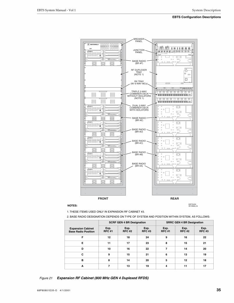
EBTS System Manual - Vol 1 System Description
EBTS Configuration Descriptions
1. THESE ITEMS USED ONLY IN EXPANSION RF CABINET #3.
2. BASE RADIO DESIGNATION DEPENDS ON TYPE OF SYSTEM AND POSITION WITHIN SYSTEM, AS FOLLOWS:
Figure 21 Expansion RF Cabinet (800 MHz GEN 4 Duplexed RFDS)
Expansion CabinetBase Radio Position
SCRF GEN 4 BR Designation SRRC GEN 4 BR Designation
Exp.RFC #1
Exp.RFC #2
Exp.RFC #3
Exp.RFC #1
Exp.RFC #2
Exp.RFC #3
F 12 18 24 9 16 22
E 11 17 23 8 15 21
D 10 16 22 7 14 20
C 9 15 21 6 13 19
B 8 14 20 5 12 18
A 7 13 19 4 11 17
NOTES: EBTS455051998LLN
FRONT REAR
IN OUTETHERNET 5 MHz/1PPS
ISOLATED GROUND
RX3 RX2 RX1GPS BGPS ABMR ANTTX OUT
ALARMIN OUT ETHERNET(GROUNDED)
3X RECEIVERINSERT ONLY IN SLOT RX2 WITH BACKPLANE 0183625
EXCITER CONTROLRESETB R P S E X PA C T L R 1 R 2 R 3STATUS
40WPOWER AMPLIFIER
POWER SUPPLY
3X RECEIVERINSERT ONLY IN SLOT RX2 WITH BACKPLANE 0183625
EXCITER CONTROLRESETB R P S E X PA C T L R 1 R 2 R 3STATUS
40WPOWER AMPLIFIER
POWER SUPPLY
3X RECEIVERINSERT ONLY IN SLOT RX2 WITH BACKPLANE 0183625
EXCITER CONTROLRESETB R P S E X PA C T L R 1 R 2 R 3STATUS
40WPOWER AMPLIFIER
POWER SUPPLY
3X RECEIVERINSERT ONLY IN SLOT RX2 WITH BACKPLANE 0183625
EXCITER CONTROLRESETB R P S E X PA C T L R 1 R 2 R 3STATUS
40WPOWER AMPLIFIER
POWER SUPPLY
RFS1 EXP1 BR6 RFS2 EXP2
3A
OFF
ON
OFF
ON
OFF
ON
OFF
ON
OFF
ON
OFF
ON
OFF
ON
OFF
ON
OFF
ON
OFF
ON
OFF
ON
3A25A25A25A3A3A25A25A25A
BR1 BR3 BR5 BR2 BR4
DE
3X RECEIVERINSERT ONLY IN SLOT RX2 WITH BACKPLANE 0183625
EXCITER CONTROLRESETB R P S E X PA C T L R 1 R 2 R 3STATUS
40WPOWER AMPLIFIER
POWER SUPPLY
3X RECEIVERINSERT ONLY IN SLOT RX2 WITH BACKPLANE 0183625
EXCITER CONTROLRESETB R P S E X PA C T L R 1 R 2 R 3STATUS
40WPOWER AMPLIFIER
POWER SUPPLY
STATUS RFS3 BR3 & BR4 BR1 & BR2RFS4RFS1 & RFS2
B -48Vdc A B RETURN A
BR5 & BR6
TRIPLE 2-WAYCOMBINER DECK
WITHOUT ISOLATORS(NOTE 1)
RF DUPLEXERTRAY
(NOTE 1)
JUNCTIONPANEL
BASE RADIO(BR #F)
RX TRAY(W/ 6-WAY MCs)
BASE RADIO(BR #E)
BASE RADIO(BR #D)
BASE RADIO(BR #C)
BASE RADIO(BR #B)
BASE RADIO(BR #A)
BREAKERPANEL
DUAL 3-WAYCOMBINER DECKWITH ISOLATORS
68P80801E35-O 4/1/2001 35

System Description EBTS System Manual - Vol 1
EBTS Configuration Descriptions
EBTS514032698JNM
SURGE
PROTECTED
SURGE
PROTECTED
SURGE
PROTECTED
DC INJECTORS
TTA ALARM TRAY
Figure 22 GEN 4 Duplexed RFDS Tower Top Amplifier FRUs/Assemblies
36 68P80801E35-O 4/1/2001

EBTS System Manual - Vol 1 System Description
EBTS Configuration Descriptions
SRRC EBTS Using 800 MHz GEN 4 Duplexed RFDS The SRRC is functionally similar to SCRF configurations. However, in the SRRC a portion of Base Radio space is used instead for the controller subsystem consisting of Gen 3 SCs and an EAS. (Refer to the EBTS Overall Functional Description and EBTS Component Descriptions paragraphs earlier in this section for block diagram interface and functional descriptions of the Gen 3 SC and EAS.)
Figure 23 shows a simplified block diagram of the GEN 4 RFDS used in the SRRC configuration. The SRRC configuration uses the same assemblies as the 800 MHz GEN 4 Duplexed RFDS as described earlier for the SCRF configuration. As such, the SRRC GEN4 configuration is functionally similar to the GEN 4 SCRF configuration, except as follows:
The baseline configuration is equipped with three BRs. The space for BR4 and BR5 are replaced instead with an EAS and two Gen 3 SCs (one main, one redundant). In the baseline configuration, the fourth BR position (located at the top of the rack) is not installed; however, the cabinet is pre-cabled to accept a total of four BRs.
A special breaker panel is used to accommodate both the RF components and the Control components.
For expansion, the SRRC configuration uses standard GEN 4 Expansion RF Cabinets fitted with up to six BRs. As such, the SRRC configuration allows a maximum of 16 channels in a three-branch diversity site. (The configuration can be expanded to provide 22 channels by adding a third Expansion RF Cabinet equipped with a Duplexer and the appropriate RF distribution hardware to support six more BRs. (This cabinet is connected to a fourth, TX-only antenna.)
Receive Description
Receive operation for the SRRC configuration is identical to that used in the GEN 4 SCRF configuration, except that three of the six Local Expansion Multicoupler Rx outputs for the Rx1-Rx3 signals are terminated, thereby feeding three outputs for each diversity branch to three Base Radios. Refer to Receive Description in the SCRF EBTS Using 800 MHz GEN 4 Duplexed RFDS paragraph earlier in this section for more information.
68P80801E35-O 4/1/2001 37

System Description EBTS System Manual - Vol 1
EBTS Configuration Descriptions
Transmit Description
Transmit operation for the SRRC configuration is identical to that used in the SCRF configuration, except that the Dual Three-Way Combiner Deck inputs normally connected to BR5 and BR6 are left unconnected. Combining points are represented by circles in Figure 23.
Note in Figure 23 that while all three antenna/duplexers are used for receive, the basic configuration uses only one of the antenna/duplexers for transmitting.
In the three-BR basic configuration, the three Tx signals from BR1 through BR3 are fed to the first of two 3-way combiners in the Dual 3-Way Combiner Deck. The combined output is then fed to the Tx input port of Duplexer 1.
From the basic configuration, the SRRC expansion configurations are modularly expanded at the following break points:
1-9 BR Expansion
1-10 BR Expansion
1-16 BR Expansion
1-22 BR Expansion
In the 1-9 BR expansion, no additional hardware or modifications are required for the SRRC primary cabinet. One-half of a Dual 3-Way Combiner Deck in an Expansion RF Cabinet combines the three Tx signals from BR4 through BR6 onto one line. The combined signal is then directly applied to the Tx input port of Duplexer 2 in the SRRC primary cabinet. Similarly, the second-half of the Dual 3-Way Combiner Deck in the Expansion RF Cabinet combines the three Tx signals from BR7 through BR9 onto one line. This combined signal is then directly applied to the Tx input port of Duplexer 3 in the SRRC primary cabinet.
In the 1-10 BR and 1-16 BR expansions, a Triple 2-Way Combining Deck in the SRRC primary cabinet is added and used in conjunction with the Dual 3-Way Combiner Decks in the SRRC primary cabinet and the Expansion RF Cabinets. The Dual 3-Way Combiner Decks are cascaded with the Triple 2-Way Combining Deck to provide combining of up to six Tx signals per Duplexer.
A fourth BR is added in the SRRC primary cabinet. The transmit output of BR10 is simply connected to one of the previously unused ports of the primary cabinet Dual 3-Way Combiner Deck.
38 68P80801E35-O 4/1/2001

EBTS System Manual - Vol 1 System Description
EBTS Configuration Descriptions
In the 1-10 and 1-16 BR expansions, the combined pair of signals (each consisting of three Tx signals) from the SRRC primary cabinet Dual 3-Way Combiner Deck are fed to the first of three 2-way combiners in the Triple 2-Way Combiner Deck. The cascaded combined signal from the 2-way combiner (consisting of the four BR1 - BR3 and BR10 Tx signals) are fed to the Duplexer 1 Tx input. In an identical manner, the combined pair of Tx signals from BR4 through BR9 in Expansion RF Cabinet #1 are fed to the second 2-way combiner, which then applies its signal to the Duplexer 2 Tx input. The combined pair of Tx signals from BR11 through BR16 in Expansion RF Cabinet #2 are fed to the third 2-way combiner, which then applies its signal to the Duplexer 3 Tx input. (The combiner decks, along with the isolator function, are explained in greater detail in the Single-Rack, Redundant-Controller System section of this manual.)
NOTE
Although the normal expansion progression is from 9-BR (without a Triple 2-Way Combiner Deck) to 10-BR (with an added BR4, Triple 2-Way Combiner Deck, and an Expansion RF Cabinet), the SRRC is available as a primary cabinet equipped with four BRs, a Dual 3-Way Combiner Deck, and a Triple 2-Way Combiner Deck. This configuration utilizes the signal flow as shown for BR1 through BR4 in the “1-10 and 1-16 BR Expansions” shown in Figure 23.
Note that to go from the baseline three-BR configuration to any of the expansion configurations, only cabling additions and (in some cases) a Triple 2-Way Combiner Deck are required to implement the expansion. As such, expansion largely consists of simply adding BRs (or expansion cabinets) and intercabinet cabling.
68P80801E35-O 4/1/2001 39

System Description EBTS System Manual - Vol 1
EBTS Configuration Descriptions
Figure 23 Simplified Block Diagram (SRRC With 800 MHz GEN 4 Duplexed RFDS)
EBTS513031098JNM
DUAL 3-WAYCOMBINER
DECK
BASIC GEN 4 RFDS SRRC CONFIGURATION
RX 3
RX 2
RX 1
BR3
TX3
RX 3
RX 2
RX 1
BR2
TX2
RX 3
RX 2
RX 1
BR1
TX1
LOCAL EXPANSION MULTICOUPLERSRX3
RX2
RX1
FIRST MULTICOUPLERSRX3
RX2
RX1
RX3
RX2
RX1
TO EXPANSIONRF CABINETS
3
TX RX
ANT 3DUPLEXER
2
TX RX
ANT 2DUPLEXER
1
TX RX
ANT 1DUPLEXER
PRIMARYCABINET
(CHANNELS 1-3)
1-9 BR EXPANSION
EXPANSIONRF CABINET
(CHANNELS 4-9)
BR3
BR2
BR1
TX3
TX2
TX1
1
TX RX
2
TX RX
3
TX RX
BR9
BR8
BR7
TX9
TX8
TX7
BR6
BR5
BR4
TX6
TX5
TX4
PRIMARY CABINET(CHANNELS 1-3, 10)
EXPANSIONRF CABINET #1(CHANNELS 4-9)
EXPANSIONRF CABINET #2
(CHANNELS 11-16)
BR3
BR2
BR1
TX3
TX2
TX1
BR10
TX10
BR9
BR8
BR6
BR5
BR4
TX9
TX8
TX6
TX5
TX4
BR7
TX7
BR16
BR15
BR13
BR12
BR11
TX16
TX15
TX13
TX12
TX11
BR14
TX14
1
TX RX
2
TX RX
3
TX RX
TRIPLE 2-WAYCOMBINER
DECK
1-10 AND 1-16 BR EXPANSIONS
EXPANSIONRF CABINET #3
(CHANNELS 17-22)
BR19
BR18
BR17
TX19
TX18
TX17
4
TX RX
17-22 BR EXPANSION
BR22
BR21
TX22
TX21
BR20
TX20
TRIPLE 2-WAYCOMBINER
DECK
40 68P80801E35-O 4/1/2001

EBTS System Manual - Vol 1 System Description
EBTS Configuration Descriptions
SRRC Primary Cabinet
Figure 24 shows the front and rear views of the SRRC primary cabinet. The SRRC primary cabinet consists of the following components and subassemblies:
Two Gen 3 SCs and one EAS
Rx Tray – provides receive distribution, power supply, alarm, and power interconnect functions within the RFDS. It is equipped with:
three First Rx Multicouplers (4-way)
three Expansion (local) Rx Multicouplers (6-way)
two power supply boards
an alarm board
an I/O board
Dual 3-Way Combiner Deck with Isolators
Triple 2-Way Combiner Deck without Isolators (only in systems using more than 9 BRs; or system with primary cabinet equipped with four BRs)
Duplexer Tray with three Duplexer Filters (Duplexers)
Base Radios
SRRC Expansion RF Cabinet
Expansion RF Cabinets used in conjunction with the SRRC primary cabinet are identical to the 800 MHz GEN 4 Duplexed RFDS Expansion RF Cabinet described earlier and shown in Figure 21. One or more Expansion RF Cabinets are used wherever an SRRC site uses more than four BRs. The Expansion RF Cabinet consists of the following subassemblies:
Rx Tray (as above), equipped with three Expansion (local) Rx Multicouplers (6-way)
Dual 3-Way Combiner Deck with Isolators
Duplexer Tray with one Duplexer (only in 17-22 BR expansion systems)
Triple 2-Way Combiner Deck without Isolators (only in 17-22 BR expansion systems)
Base Radios
Duplexed Tower Top Amplifier Incorporation
Duplexed Tower Top Amplifier (DTTA) incorporation into the SRRC configuration is identical to that of the SCRF 800 MHz GEN 4 RFDS. Refer to the Duplexed Tower Top Amplifier Incorporation discussion in the earlier SCRF EBTS Using 800 MHz GEN 4 Duplexed RFDS paragraph earlier in this section for information.
68P80801E35-O 4/1/2001 41
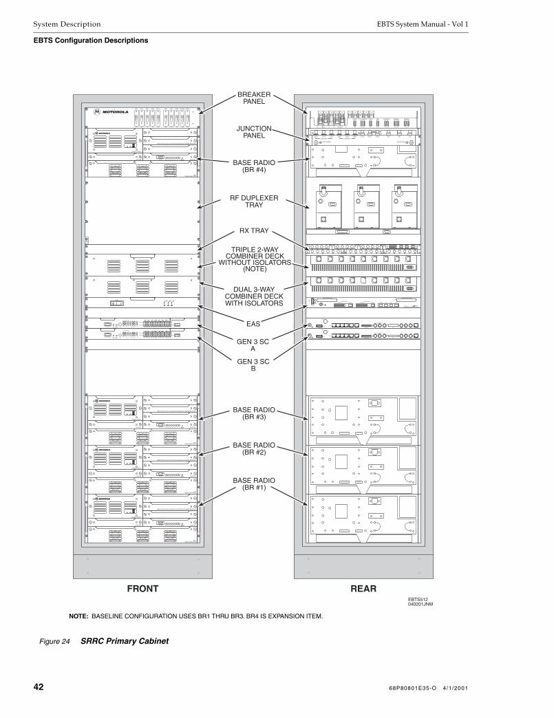
System Description EBTS System Manual - Vol 1
EBTS Configuration Descriptions
Figure 24 SRRC Primary Cabinet
FRONT REAR
3X RECEIVERINSERT ONLY IN SLOT RX2 WITH BACKPLANE 0183625
EXCITER CONTROLRESETB R P S E X PA C T L R 1 R 2 R 3STATUS
40WPOWER AMPLIFIER
POWER SUPPLY
3X RECEIVERINSERT ONLY IN SLOT RX2 WITH BACKPLANE 0183625
EXCITER CONTROLRESETB R P S E X PA C T L R 1 R 2 R 3STATUS
40WPOWER AMPLIFIER
POWER SUPPLY
3X RECEIVERINSERT ONLY IN SLOT RX2 WITH BACKPLANE 0183625
EXCITER CONTROLRESETB R P S E X PA C T L R 1 R 2 R 3STATUS
40WPOWER AMPLIFIER
POWER SUPPLY
3X RECEIVERINSERT ONLY IN SLOT RX2 WITH BACKPLANE 0183625
EXCITER CONTROLRESETB R P S E X PA C T L R 1 R 2 R 3STATUS
40WPOWER AMPLIFIER
POWER SUPPLY
EBTS512040201JNM
RFS3 CTRL A RFS2 EAS/IMU CTRL B
OFF
ON
OFF
ON
OFF
ON
OFF
ON
OFF
ON
OFF
ON
OFF
ON
OFF
ON
OFF
ON
OFF
ON
OFF
ON
3A25A25A3A3A 7.5A25A25A
BR1 BR3 RFS1 BR2 BR4
7.5A 7.5A
ON ON ON ON ON ON ON
STATUS CTRL B RFS3 RFS1&RFS2 BR3&BR4 BR1&BR2CTRL A EAS/IMU
B -48Vdc A B RETURN A
10B2-1123 10/100B-T10B2-210B2-3X.21
SITE REF OUT
PARALLELSERIALREDUND4321
T1/E1
GPS
-48V RTN
BAT
Input
Active
Output
Active
Power
OnPOWER
EqpMonNet
1
EqpMonNet
2
EqpMonNet
3
EqpMonNet
4
Net Eqp
Net Eqp
1234GPSActi
ve
Power
LOS/Yellow
AISFE/CRC
BPV/PD
NetLocal
MonAbort/Reset
Sel/Loop
Service Access
DCE
PowerOOF
EqpMonNet
1
EqpMonNet
2
EqpMonNet
3
EqpMonNet
4
Net Eqp
Net Eqp
1234GPSActi
ve
Power
LOS/Yellow
AISFE/CRC
BPV/PD
NetLocal
MonAbort/Reset
Sel/Loop
Service Access
DCE
PowerOOF
RF#3RF#2RF#1CONTROLSERIALPARALLELCONTROLLER B
SERIALPARALLELCONTROLLER A
RTN
-48V
USER ALARM/CONTROL SYSTEM ALARM/CONTROL
ENVIRONMENTAL ALARM SYSTEMMotorola -48V , 1.0A
10B2-1123 10/100B-T10B2-210B2-3X.21
SITE REF OUT
PARALLELSERIALREDUND4321
T1/E1
GPS
-48V RTN
BAT
GPS BGPS AOUT 3 OUT 2 OUT 1 10B2-3 10B2-2 10B2-1 TX OUT RX2RX3 RX1
5MHz/1PPS ETHERNET
SITE GROUND SITE GROUND
JUNCTIONPANEL
BASE RADIO(BR #4)
RF DUPLEXERTRAY
BASE RADIO(BR #3)
BASE RADIO(BR #2)
BASE RADIO(BR #1)
BREAKERPANEL
GEN 3 SCB
GEN 3 SCA
EAS
TRIPLE 2-WAYCOMBINER DECK
WITHOUT ISOLATORS(NOTE)
DUAL 3-WAYCOMBINER DECKWITH ISOLATORS
RX TRAY
NOTE: BASELINE CONFIGURATION USES BR1 THRU BR3. BR4 IS EXPANSION ITEM.
42 68P80801E35-O 4/1/2001

EBTS System Manual - Vol 1 System Description
EBTS Configuration Descriptions
SRSC EBTS Using 800 MHz GEN 4 Duplexed RFDS
The SRSC is functionally similar to the SCRF GEN 4 configurations. However, in the SRSC a portion of Base Radio space is used instead for the controller subsystem consisting of a Gen 3 SC and an EAS, and an AC/DC Power System (which is not part of the EBTS for all other configurations). (Refer to the EBTS Overall Functional Description and EBTS Component Descriptions paragraphs earlier in this section for block diagram interface and functional descriptions of the Gen 3 SC and EAS.)
As such, the SRSC EBTS is a single cabinet, stand-alone, non-expandable 3-BR EBTS which can simply be directly connected to the site antennas, T1/E1 interface, and AC mains.
Figure 25 shows a simplified block diagram of the GEN 4 RFDS used in the SRSC configuration. The SRSC configuration uses some of the same assemblies as the 800 MHz GEN 4 Duplexed RFDS, as described earlier for the SCRF configuration. As such, the SRSC is functionally similar to the GEN 4 SCRF configuration, except as follows:
The configuration is equipped with three BRs (maximum). The space for BR4 and BR5 are replaced instead with an EAS and a Gen 3 SC.
Because the SRSC configuration is limited to three BRs, transmit combining and receive expansion is not required. A Triple Isolator Deck is used to couple the three BR TX outputs to the three duplexers. In the Rx Tray, the First (4-Way) Multicouplers directly feed the three BRs (The Expansion (6-Way) Multicouplers are not used.)
The fourth BR position (located at the top of the rack) is not installed. In its place, an AC/DC Power System is installed.
A special breaker panel is used to accommodate both the RF components and the Control components.
Receive Description
The three receive signals (Rx1 through Rx3) from the three duplexer/antenna arrangements are applied to three respective receivers in each Base Radio, thereby providing receive diversity. The distribution of the individual Rx1-Rx3 signals from the duplexers/antennas to multiple Base Radios is provided by First Multicouplers (MCs). Each First MC takes its Rx signal from the antenna (via the Duplexer Rx output) and provides four outputs which are available for use by the Base Radios. Three of the four outputs of each MC are fed to respective Rx1-Rx3 inputs of each Base Radio (the fourth output of each MC is not used and is terminated).
Transmit Description
In addition to three Duplexers, the SRSC is equipped with a Triple Isolator Deck. The three Tx signals from BR1 through BR3 are respectively fed through the three isolators in the deck and then applied to the duplexer Tx inputs. (The isolator function is explained in greater detail in the
Single Rack, Single Controller GEN 4
EBTS
section later in this manual.)
68P80801E35-O 4/1/2001 43

System Description EBTS System Manual - Vol 1
EBTS Configuration Descriptions
Figure 25
Simplified Block Diagram (SRSC With 800 MHz GEN 4 Duplexed RFDS)
SRSC Cabinet
Figure 26 shows the front and rear views of the SRSC cabinet. The SRSC primary cabinet consists of the following components and subassemblies:
AC/DC Power System
Gen 3 SC and EAS
Rx Tray – provides receive distribution, power supply, alarm, and power interconnect functions within the RFDS. It is equipped with:
three First Rx Multicouplers (4-way)
two power supply boards
an alarm board
an I/O board
Triple Isolator Deck
Duplexer Tray with three Duplexer Filters (Duplexers)
Base Radios
Duplexed Tower Top Amplifier Incorporation
Duplexed Tower Top Amplifier (DTTA) incorporation into the SRSC configuration is identical to that of the SCRF 800 MHz GEN 4 RFDS. Refer to the Duplexed Tower Top Amplifier Incorporation discussion in the earlier SCRF EBTS Using 800 MHz GEN 4 Duplexed RFDS paragraph earlier in this section for information.
TRIPLEISOLATOR
DECK
EBTS578041798JNM
RX 3
RX 2
RX 1
BR3
TX3
RX 3
RX 2
RX 1
BR2
TX2
RX 3
RX 2
RX 1
BR1
TX1
FIRST MULTICOUPLERSRX3
RX2
RX1
3
TX RX
ANT 3DUPLEXER
2
TX RX
ANT 2DUPLEXER
1
TX RX
ANT 1DUPLEXER
44 68P80801E35-O 4/1/2001
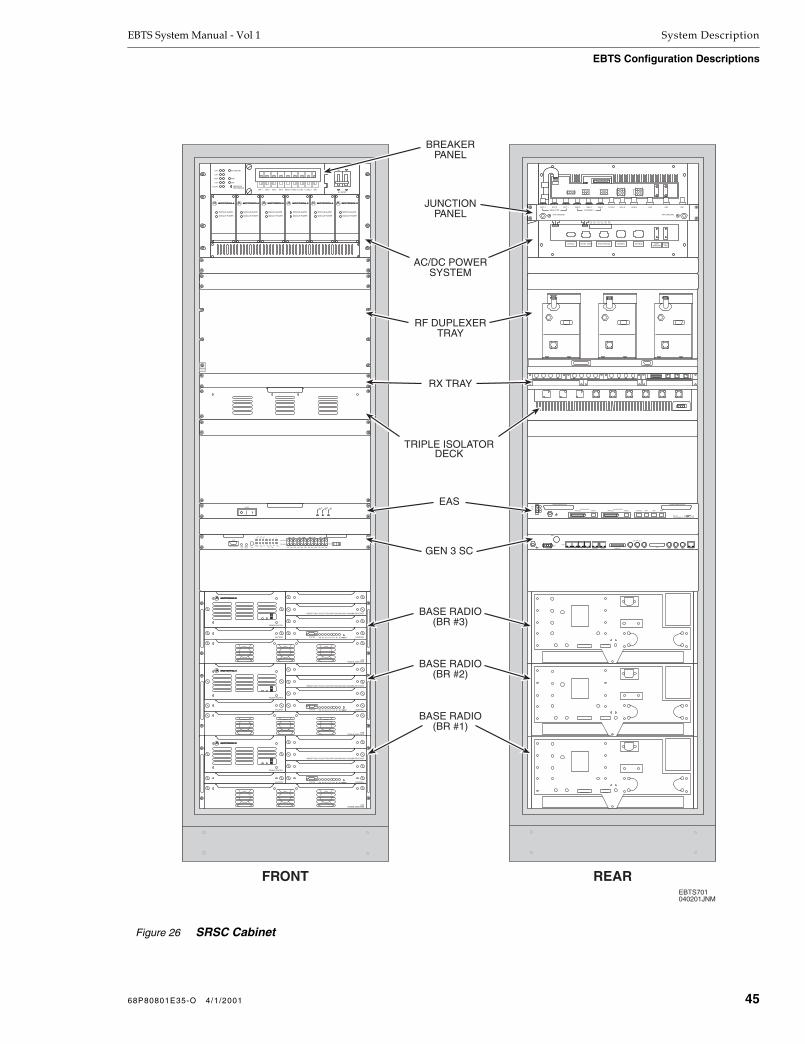
EBTS System Manual - Vol 1 System Description
EBTS Configuration Descriptions
Figure 26
SRSC Cabinet
10B2-1123 10/100B-T10B2-210B2-3X.21
SITE REF OUT
PARALLELSERIALREDUND4321
T1/E1
GPS
-48V RTN
BAT
RF#3RF#2RF#1CONTROLSERIALPARALLELCONTROLLER B
SERIALPARALLELCONTROLLER A
RTN
-48V
USER ALARM/CONTROL SYSTEM ALARM/CONTROL
ENVIRONMENTAL ALARM SYSTEMMotorola -48V , 1.0A
G L1 L2
AC INPUT
G T +12V
TEMP SENSOR
CNTRL 2 CNTRL 1/IMU RFDS1/RFDS2 BR3/BR4 BR1/BR2 BATTGROUND
BATT-48V
CBA ACF HVA LVA MIN MAJ
FRONT REAR
3X RECEIVERINSERT ONLY IN SLOT RX2 WITH BACKPLANE 0183625
EXCITER CONTROLRESETB R P S E X PA C T L R 1 R 2 R 3STATUS
40WPOWER AMPLIFIER
POWER SUPPLY
3X RECEIVERINSERT ONLY IN SLOT RX2 WITH BACKPLANE 0183625
EXCITER CONTROLRESETB R P S E X PA C T L R 1 R 2 R 3STATUS
40WPOWER AMPLIFIER
POWER SUPPLY
3X RECEIVERINSERT ONLY IN SLOT RX2 WITH BACKPLANE 0183625
EXCITER CONTROLRESETB R P S E X PA C T L R 1 R 2 R 3STATUS
40WPOWER AMPLIFIER
POWER SUPPLY
EBTS701040201JNM
LVD
NEGATIVEREFERENCE
LVR
HVA
LVA
FLOAT
DC ONLINE
HVA
LVA
AC INPUT
MODULE ALARM
MODULE POWER
MODULE ALARM
MODULE POWER
MODULE ALARM
MODULE POWER
MODULE ALARM
MODULE POWER
MODULE ALARM
MODULE POWER
MODULE ALARM
MODULE POWER
BR 1 BR 2 BR 3 BR 4 RFDS 1 RFDS 2 CTRL 1 CTRL 2 IMU
GPS BGPS AOUT 3 OUT 2 OUT 1 10B2-3 10B2-2 10B2-1 TX OUT RX2RX3 RX1
5MHz/1PPS ETHERNET
Input
Active
Output
Active
Power
OnPOWER
EqpMonNet
1
EqpMonNet
2
EqpMonNet
3
EqpMonNet
4
Net Eqp
Net Eqp
1234GPSActi
ve
Power
LOS/Yellow
AISFE/CRC
BPV/PD
NetLocalMon
Abort/Reset
Sel/Loop
Service Access
DCE
PowerOOF
SITE GROUND SITE GROUND
JUNCTIONPANEL
AC/DC POWERSYSTEM
RF DUPLEXERTRAY
BASE RADIO(BR #3)
BASE RADIO(BR #2)
BASE RADIO(BR #1)
BREAKERPANEL
GEN 3 SC
EAS
TRIPLE ISOLATORDECK
RX TRAY
68P80801E35-O 4/1/2001 45

System Description EBTS System Manual - Vol 1
EBTS Configuration Descriptions
Cavity Combining RFDS
Cavity Combining RFDS Configurations
The cavity combining RFDS is a 800 MHz, non-duplexed RF combining system. This RFDS uses up to three receive antennas. For each cavity combiner, a single transmit antenna is used. Figure 27 is a simplified block diagram showing the signal flow between the antennas, RFDS, and Base Radios in a three-branch cavity combining system.
The Basic Cavity Combining Configuration shown in Figure 27 is the starting basis for all three-branch cavity combining RFDS configurations. Each Base Radio transmit (Tx) signal is fed to an individual cavity input of the RFDS. These inputs are combined by the RFDS and applied to a common Tx antenna. However, the three receive signals (Rx1 through Rx3) from the three Rx antennas are applied to three respective receivers in each Base Radio, thereby providing receive diversity. The distribution of the individual Rx1-Rx3 signals from the Rx antennas to multiple Base Radios is provided by Receive Splitters. Each Receive Splitter takes its Rx signal from the antenna and provides multiple outputs which are then fed to respective Rx inputs of each Base Radio.
All cavity combining RFDS configurations use the Receive Splitter arrangement shown in Figure 27 to provide the Rx1-Rx3 signals to each Base Radio.
The Expansion Configurations shown in Figure 27 show the Tx signal flow for various cavity combining configurations. Noting that the Rx signal distribution is identical to that discussed above, only the Tx signal paths are discussed. (Where used, an expansion cabinet will use additional Receive Splitters which are fed from outputs on the main RF cabinet Receive Splitter. The Receive Splitters used in the expansion RF cabinet distribute the Rx1-Rx3 signals in a manner identical to that shown for the Basic Cavity Combining Configuration.)
For the Tx signals, all expansion configurations make use of a phasing harness (represented by circles in Figure 27) to combine Tx signals from two cavity combiners onto a single Tx antenna feed. As shown, this arrangement allows symmetrical doubling of the number of Base Radios and, therefore, the number of channels. Up to 10 channels can be accommodated per combiner pair/phasing harness. A functional duplication of the 1-10 channel expansion results in the 20-channel expansion system. (Note that this system requires two separate Tx antennas.)
46 68P80801E35-O 4/1/2001

EBTS System Manual - Vol 1 System Description
EBTS Configuration Descriptions
Figure 27
Simplified Block Diagram (Cavity Combining RFDS Configurations)
CAVITY
1
CAVITY
2
CAVITY
3
CAVITY
4
CAVITY
5
EBTS364061097LLN
BASIC CAVITY COMBINING CONFIGURATION
RFDS
RECEIVE SPLITTERSRX3
RX2
RX1
TX
RX 3
RX 2
RX 1
BASE RADIO5
RX 3
RX 2
RX 1
BASE RADIO4
RX 3
RX 2
RX 1
BASE RADIO3
RX 3
RX 2
RX 1
BASE RADIO2
RX 3
RX 2
RX 1
BASE RADIO1
CAVITY
1
CAVITY
2
CAVITY
3
CAVITY
4
CAVITY
5
RFDS
RX 3
RX 2
RX 1
BASE RADIO5
RX 3
RX 2
RX 1
BASE RADIO4
RX 3
RX 2
RX 1
BASE RADIO3
RX 3
RX 2
RX 1
BASE RADIO2
RX 3
RX 2
RX 1
BASE RADIO1
CAVITY
1
CAVITY
2
CAVITY
3
CAVITY
4
CAVITY
5
RFDS
RX 3
RX 2
RX 1
BASE RADIO10
RX 3
RX 2
RX 1
BASE RADIO9
RX 3
RX 2
RX 1
BASE RADIO8
RX 3
RX 2
RX 1
BASE RADIO7
RX 3
RX 2
RX 1
BASE RADIO6
CAVITY
1
CAVITY
2
CAVITY
3
CAVITY
4
CAVITY
5
RFDS
RX 3
RX 2
RX 1
BASE RADIO15
RX 3
RX 2
RX 1
BASE RADIO14
RX 3
RX 2
RX 1
BASE RADIO13
RX 3
RX 2
RX 1
BASE RADIO12
RX 3
RX 2
RX 1
BASE RADIO11
CAVITY
1
CAVITY
2
CAVITY
3
CAVITY
4
CAVITY
5
RFDS
RX 3
RX 2
RX 1
BASE RADIO20
RX 3
RX 2
RX 1
BASE RADIO19
RX 3
RX 2
RX 1
BASE RADIO18
RX 3
RX 2
RX 1
BASE RADIO17
RX 3
RX 2
RX 1
BASE RADIO16
TX11-20
TX1-10
EXPANSIONCONFIGURATIONS
11-20 CHANNEL6-10 CHANNEL
TX
TX
TX
TX
TX
RECEIVE EXPANSION SPLITTERSRX3
RX2
RX1
RX3
RX2
RX1
TO BASE RADIO nRECEIVERS(OR EXPANSIONRF CABINETS)
RX3RX2RX1
68P80801E35-O 4/1/2001 47

System Description EBTS System Manual - Vol 1
EBTS Configuration Descriptions
Cavity Combining RFDS Main Cabinet
Figure 28 shows the front and rear views of the RF Cabinet with a cavity combining RFDS installed.
The main cabinet of the cavity combining RFDS consists of the following FRUs/assemblies:
TLN3392 DC Power Distribution and Alarm Tray with two Power Supplies (PS1 and PS2) – provides DC power and alarm monitoring for the amplifiers in the Tower Top Amplifiers and/or the receive amplifiers in the Receiver Distribution Trays.
Up to three Receiver Distribution Multicoupler (Splitter) Trays
RF Distribution DC Injector
Power Monitor Assembly
Up to five Cavities
Up to five Isolator/Load Assemblies
Base Radios
Cavity Combining RFDS Expansion Cabinets
As stated earlier, the cavity combining system can be expanded to 20 channels. Depending on the channels covered by an expansion cabinet, the expansion cabinet is equipped as described below. Cavity expansion cabinets use some additional assemblies as used in the main cavity combining RFDS cabinet to provide expansion.
The cavity expansion RFDS cabinet used for channels 6-10 and channels 16-20 consists of the following subassemblies:
Up to five Cavities
Up to five Isolator/Load Assemblies
Up to three Receiver Distribution Multicoupler (Splitter) Trays
DC Power Distribution and Alarm Tray with two Power Supplies (PS1 and PS2)
Base Radios
The cavity expansion RFDS cabinet used for channels 11-15 consists of the following subassemblies:
DC Power Distribution and Alarm Tray with two Power Supplies (PS1 and PS2)
Up to three Receiver Distribution Multicoupler (Splitter) Trays
Power Monitor Assembly
Up to five Cavities
Up to five Isolator/Load Assemblies
Base Radios
48 68P80801E35-O 4/1/2001
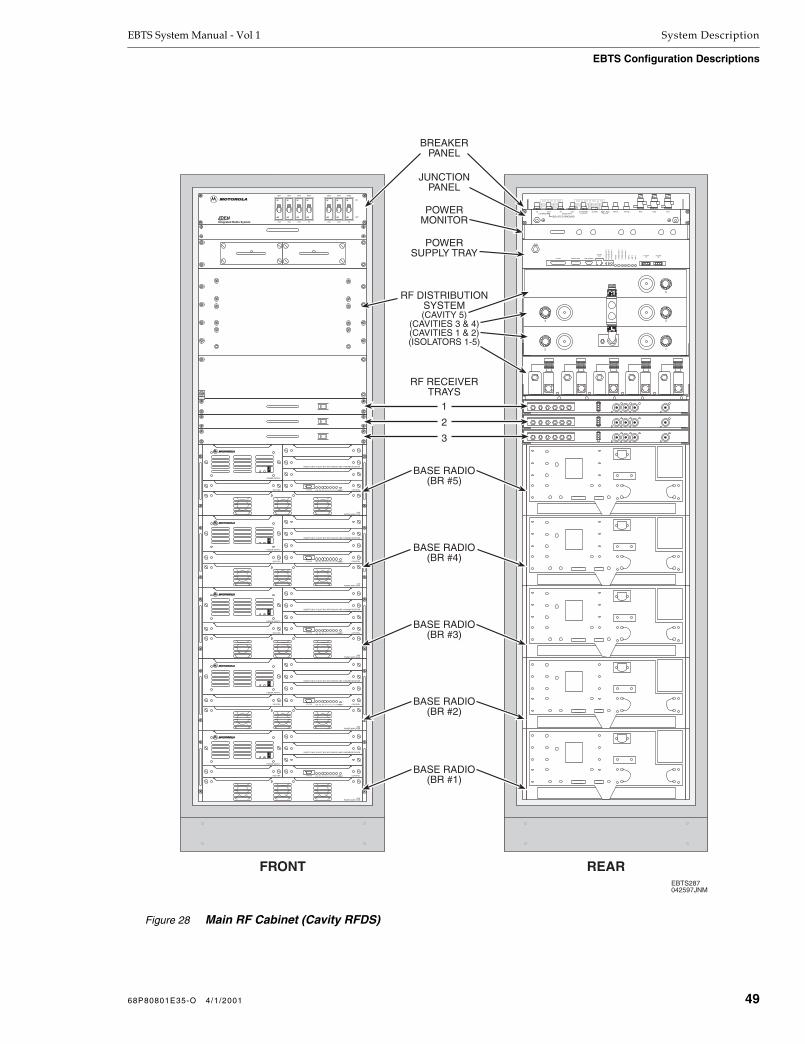
EBTS System Manual - Vol 1 System Description
EBTS Configuration Descriptions
EBTS287042597JNM
FRONT REAR
GND
B -48Vdc A B RETURN A
ALARM POWER MON. AMP POWER
POWERIN
PO
WE
R A
MP
3
PO
WE
R A
MP
2
PO
WE
R A
MP
1
RE
SE
T
TO
WE
R A
MP
3
TO
WE
R A
MP
2
TO
WE
R A
MP
1
AM
P 3
AM
P 2
AM
P 1
ALARMOUU POWER
IN
2
4 3
5
1
OFF
ON
BR1
25A
OFF
ON
BR3
25A
OFF
ON
BR5
25A
OFF
ON
RFS1
3A
OFF
ON
BR2
25A
OFF
ON
BR4
25A
OFF
ON
RFS2
3A
OFF
ON
DEIntegrated Radio System
3X RECEIVERINSERT ONLY IN SLOT RX2 WITH BACKPLANE 0183625
EXCITER CONTROLRESETB R P S E X PA C T L R 1 R 2 R 3STATUS
40WPOWER AMPLIFIER
POWER SUPPLY
3X RECEIVERINSERT ONLY IN SLOT RX2 WITH BACKPLANE 0183625
EXCITER CONTROLRESETB R P S E X PA C T L R 1 R 2 R 3STATUS
40WPOWER AMPLIFIER
POWER SUPPLY
3X RECEIVERINSERT ONLY IN SLOT RX2 WITH BACKPLANE 0183625
EXCITER CONTROLRESETB R P S E X PA C T L R 1 R 2 R 3STATUS
40WPOWER AMPLIFIER
POWER SUPPLY
3X RECEIVERINSERT ONLY IN SLOT RX2 WITH BACKPLANE 0183625
EXCITER CONTROLRESETB R P S E X PA C T L R 1 R 2 R 3STATUS
40WPOWER AMPLIFIER
POWER SUPPLY
3X RECEIVERINSERT ONLY IN SLOT RX2 WITH BACKPLANE 0183625
EXCITER CONTROLRESETB R P S E X PA C T L R 1 R 2 R 3STATUS
40WPOWER AMPLIFIER
POWER SUPPLY
IN OUTETHERNET 5 MHz/1PPS
ISOLATED GROUND
RX3 RX2 RX1GPS BGPS ABMR ANTTX OUT
ALARMIN OUT ETHERNET(GROUNDED)
BREAKERPANEL
BASE RADIO(BR #1)
BASE RADIO(BR #2)
BASE RADIO(BR #3)
BASE RADIO(BR #4)
BASE RADIO(BR #5)
RF RECEIVERTRAYS
JUNCTIONPANEL
1
2
3
POWERMONITOR
POWERSUPPLY TRAY
RF DISTRIBUTIONSYSTEM(CAVITY 5)
(CAVITIES 3 & 4)(CAVITIES 1 & 2)(ISOLATORS 1-5)
Figure 28
Main RF Cabinet (Cavity RFDS)
68P80801E35-O 4/1/2001 49
System Description EBTS System Manual - Vol 1
EBTS Configuration Descriptions
900 MHz Duplexed RFDS
The 900 MHz Duplexed RFDS is a hybrid duplexed, expansion-enhanced duplexed RFDS that allows a receive and transmit path to share a common antenna. This is accomplished through the use of up to three duplexers which serve three antennas. The 900 MHz duplexed RFDS employs hybrid combining in a modularized, compact design. The compact design of the combining assembly allows up to six Base Radios (BRs) per RF cabinet in an 900 MHz duplexed RFDS system. An expansion is available which adds an additional 6 channels (channels 7-12) using an added expansion RF cabinet and additional antennas.
Figure 29 shows simplified block diagrams of various 900 MHz duplexed RFDS configurations. The Basic 900 MHz duplexed RFDS Configuration shown in Figure 29 is the starting basis for all 900 MHz duplexed RFDS configurations.
Receive Description
The three receive signals (Rx1 through Rx3) from the three duplexer/antenna arrangements are applied to three respective receivers in each Base Radio, thereby providing receive diversity. The distribution of the individual Rx1-Rx3 signals from the duplexers/antennas to multiple Base Radios is provided by Receive Multicouplers (RMCs). Each RMC takes its Rx signal from the antenna (via the Duplexer Rx output) and provides multiple outputs which are available for the respective Rx1-Rx3 inputs of each Base Radio.
In a 1-6 BR system, the Main RF Cabinet Receive Multicouplers provide the six distribution outputs of each Rx branch for the six Base Radios. However, in the 1-12 BR expansion system, the six outputs of the main cabinet multicoupler do not directly drive the Base Radios. Instead, a distribution output for each branch is fed to the input of a second group of multicouplers located in an Rx Tray. The Rx Tray multicouplers, in turn, now provide the Rx signals for the six Base Radios in the Main RF Cabinet.
Similar to the Rx Tray arrangement used in the Main RF Cabinet, an Rx Tray located in the Expansion RF Cabinet receives the three branch diversity Rx signals from the main cabinet Receive Multicouplers. The expansion cabinet Rx Tray multicouplers provide the Rx signals for the six Base Radios in the Expansion RF Cabinet.
Transmit Description
The Basic duplexed configuration shown in Figure 29 is the starting basis for all three-branch duplexed RFDS configurations. In this configuration, the three Base Radio transmit (Tx) signals are respectively applied to a dedicated duplexer/antenna.
In expansion configurations, (1-6 BR and 1-12 BR), the Main RF Cabinet is equipped with a Triple 2-Way Combiner Deck that combines up to six Tx signals onto three lines to accommodate up to six BRs in the Main RF Cabinet. Combining points are represented by circles in Figure 29.
50 68P80801E35-O 4/1/2001

EBTS System Manual - Vol 1 System Description
EBTS Configuration Descriptions
In the 6-BR configuration, the two Tx signals from BR1 and BR4 are fed to the first of three 2-way combiners in the Triple 2-Way Combiner Deck. The combined output is then fed to the Tx input port of Duplexer 1. Similarly, the two Tx signals from BR2 and BR5 are fed to the second of three 2-way combiners in the combiner deck. The combined Tx signal is then fed to the Tx input port of Duplexer 2. The two TX signals from BR3 and BR6 are similarly applied to the Tx input port of Duplexer 3.
In the 1-12 BR system expansion, Triple 2-Way Combining Decks in the Expansion RF Cabinet are used to accommodate the Tx signals from Base Radios 7 through 12. The Tx system for BRs 7-12 are completely independent from that used for BRs 1-6 in the Main RF Cabinet.
In the expansion cabinet, three pairs of Tx signals (TX7/TX8, TX9/TX10, and TX11/TX12) are combined into three lines by a Triple 2-Way Combiner Deck identical to that used in the Main RF Cabinet. The first two combined signals, in turn, are again applied to a Dual 2-Way Combiner Deck without Isolators. The TX7/TX8 combined signal is combined with the TX9/TX10 signal; the TX7-10 cascade combined signal is applied to Tx-only antenna ANT4 via a transmit filter. The TX11/TX12 combined signal is fed through the second combiner deck and applied to Tx-only antenna ANT5 via a transmit filter. The Dual 2-Way Combiner Deck is not equipped with isolators, since it does not accept signals directly from the Base Radio. (The combiner decks, along with the isolator function, are explained in greater detail in the 900 MHz Duplexed RF Distribution System section of this manual.)
68P80801E35-O 4/1/2001 51

System Description EBTS System Manual - Vol 1
EBTS Configuration Descriptions
Figure 29 Simplified Block Diagram (900 MHz Duplexed RFDS)
EBTS460012098JNM
MAIN RF CABINET(CHANNELS 1-6)
EXPANSION RF CABINET(CHANNELS 7-12)
12 BR EXPANSION
TRIPLE 2-WAYCOMBINER
DECKW/ ISOLATORS
RX 3
RX 2
RX 1
BR1
TX1
RX TRAY MULTICOUPLERSRX3
RX2
RX1
TRIPLE 2-WAYCOMBINER
DECKw/ ISOLATORS
RX 3
RX 2
RX 1
BR9
TX9
RX 3
RX 2
RX 1
BR8
TX8
RX 3
RX 2
RX 1
BR7
TX7
RX TRAY MULTICOUPLERSRX3
RX2
RX1
RX 3
RX 2
RX 1
BR10
TX10
RX 3
RX 2
RX 1
BR12
TX12
RX 3
RX 2
RX 1
BR11
TX11
RECEIVE MULTICOUPLERSRX3
RX2
RX1
3
TX RX
ANT 3DUPLEXER
2
TX RX
ANT 2DUPLEXER
1
TX RX
ANT 1DUPLEXER
SINGLE 2-WAYCOMBINER
DECKw/o ISOLATORS
ANT5
ANT4
RX 3
RX 2
RX 1
BR6
TX6
RX 3
RX 2
RX 1
BR4
TX4
BR5
TX5
RX 3
RX 2
RX 1
RX 3
RX 2
RX 1
BR3
TX3
TRIPLE 2-WAYCOMBINER
DECK
RX 3
RX 2
RX 1
BR2
TX2
RX 3
RX 2
RX 1
BR4
TX4
RX 3
RX 2
RX 1
BR1
TX1
RECEIVE MULTICOUPLERSRX3
RX2
RX1
RX 3
RX 2
RX 1
BR5
TX5
RX 3
RX 2
RX 1
BR6
TX6
RX 3
RX 2
RX 1
BR3
TX3
3
TX RX
ANT 3DUPLEXER
2
TX RX
ANT 2DUPLEXER
1
TX RX
ANT 1DUPLEXER
1-6 BR CONFIGURATION
TX2
RX 3
RX 2
RX 1
BR2
TXFILTER
TXFILTER
52 68P80801E35-O 4/1/2001

EBTS System Manual - Vol 1 System Description
EBTS Configuration Descriptions
900 MHz RFDS Main RF Cabinet
Figure 30 shows the front and rear views of the 900 MHz RFDS Main RF Cabinet.
The 900 MHz RFDS Main RF Cabinet consists of the following FRUs and assemblies:
Three Receive Multicoupler/RF Amplifiers (6-way)
Redundant Power Supply Assembly
Triple 2-Way Combiner Deck
Base Radios
Either of the following trays:
DC/Alarm Tray (similar in appearance to Rx Tray, but not equipped with multicouplers; used only in systems up to 6 BRs)
Rx Tray (same as above, but equipped with three, 6-Way Receive Multicoupler boards; used only in systems with more than 6 BRs)
900 MHz RFDS Expansion RF Cabinet
Figure 31 shows the front and rear views of the 900 MHz RFDS Expansion RF Cabinet. A 900 MHz RFDS Expansion RF Cabinet is used wherever a site uses more than six BRs. The 900 MHz RFDS Expansion RF Cabinet consists of the following FRUs and assemblies:
Rx Tray, equipped with three, 6-Way Receive Multicoupler boards
Triple 2-Way Combiner Deck with Isolators
Dual 2-Way Combiner Deck without Isolators
Transmit Filter Tray
Base Radios
68P80801E35-O 4/1/2001 53

System Description EBTS System Manual - Vol 1
EBTS Configuration Descriptions
Figure 30 Main RF Cabinet (900 MHz RFDS)
FRONT
3X RECEIVERINSERT ONLY IN SLOT RX2 WITH BACKPLANE 0183625
EXCITER CONTROLRESETB R P S E X PA C T L R 1 R 2 R 3STATUS
40WPOWER AMPLIFIER
POWER SUPPLY
3X RECEIVERINSERT ONLY IN SLOT RX2 WITH BACKPLANE 0183625
EXCITER CONTROLRESETB R P S E X PA C T L R 1 R 2 R 3STATUS
40WPOWER AMPLIFIER
POWER SUPPLY
3X RECEIVERINSERT ONLY IN SLOT RX2 WITH BACKPLANE 0183625
EXCITER CONTROLRESETB R P S E X PA C T L R 1 R 2 R 3STATUS
40WPOWER AMPLIFIER
POWER SUPPLY
3X RECEIVERINSERT ONLY IN SLOT RX2 WITH BACKPLANE 0183625
EXCITER CONTROLRESETB R P S E X PA C T L R 1 R 2 R 3STATUS
40WPOWER AMPLIFIER
POWER SUPPLY
RFS1 EXP1 BR6 RFS2 EXP2
3A
OFF
ON
OFF
ON
OFF
ON
OFF
ON
OFF
ON
OFF
ON
OFF
ON
OFF
ON
OFF
ON
OFF
ON
OFF
ON
3A25A25A25A3A3A25A25A25A
BR1 BR3 BR5 BR2 BR4
DE
3X RECEIVERINSERT ONLY IN SLOT RX2 WITH BACKPLANE 0183625
EXCITER CONTROLRESETB R P S E X PA C T L R 1 R 2 R 3STATUS
40WPOWER AMPLIFIER
POWER SUPPLY
3X RECEIVERINSERT ONLY IN SLOT RX2 WITH BACKPLANE 0183625
EXCITER CONTROLRESETB R P S E X PA C T L R 1 R 2 R 3STATUS
40WPOWER AMPLIFIER
POWER SUPPLY
EBTS446120497LLN
REAR
IN OUTETHERNET 5 MHz/1PPS
ISOLATED GROUND
RX3 RX2 RX1GPS BGPS ABMR ANTTX OUT
ALARMIN OUT ETHERNET(GROUNDED)
T9IN T8IN T7OUT T6IN T5IN T3IN T2IN T1OUTT4OUT
STATUS RFS3 BR3 & BR4 BR1 & BR2RFS4RFS1 & RFS2
B -48Vdc A B RETURN A
BR5 & BR6
JUNCTIONPANEL
BASE RADIO(BR #6)
RF DISTRIBUTIONSYSTEM
RX TRAY
TRIPLE 2-WAYCOMBINER DECK
BASE RADIO(BR #5)
BASE RADIO(BR #4)
BASE RADIO(BR #3)
BASE RADIO(BR #2)
BASE RADIO(BR #1)
BREAKERPANEL
54 68P80801E35-O 4/1/2001

EBTS System Manual - Vol 1 System Description
EBTS Configuration Descriptions
Figure 31 Expansion RF Cabinet (900 MHz RFDS)
FRONT
3X RECEIVERINSERT ONLY IN SLOT RX2 WITH BACKPLANE 0183625
EXCITER CONTROLRESETB R P S E X PA C T L R 1 R 2 R 3STATUS
40WPOWER AMPLIFIER
POWER SUPPLY
3X RECEIVERINSERT ONLY IN SLOT RX2 WITH BACKPLANE 0183625
EXCITER CONTROLRESETB R P S E X PA C T L R 1 R 2 R 3STATUS
40WPOWER AMPLIFIER
POWER SUPPLY
3X RECEIVERINSERT ONLY IN SLOT RX2 WITH BACKPLANE 0183625
EXCITER CONTROLRESETB R P S E X PA C T L R 1 R 2 R 3STATUS
40WPOWER AMPLIFIER
POWER SUPPLY
3X RECEIVERINSERT ONLY IN SLOT RX2 WITH BACKPLANE 0183625
EXCITER CONTROLRESETB R P S E X PA C T L R 1 R 2 R 3STATUS
40WPOWER AMPLIFIER
POWER SUPPLY
RFS1 EXP1 BR6 RFS2 EXP2
3A
OFF
ON
OFF
ON
OFF
ON
OFF
ON
OFF
ON
OFF
ON
OFF
ON
OFF
ON
OFF
ON
OFF
ON
OFF
ON
3A25A25A25A3A3A25A25A25A
BR1 BR3 BR5 BR2 BR4
DE
3X RECEIVERINSERT ONLY IN SLOT RX2 WITH BACKPLANE 0183625
EXCITER CONTROLRESETB R P S E X PA C T L R 1 R 2 R 3STATUS
40WPOWER AMPLIFIER
POWER SUPPLY
3X RECEIVERINSERT ONLY IN SLOT RX2 WITH BACKPLANE 0183625
EXCITER CONTROLRESETB R P S E X PA C T L R 1 R 2 R 3STATUS
40WPOWER AMPLIFIER
POWER SUPPLY
EBTS458012098JNM
REAR
IN OUTETHERNET 5 MHz/1PPS
ISOLATED GROUND
RX3 RX2 RX1GPS BGPS ABMR ANTTX OUT
ALARMIN OUT ETHERNET(GROUNDED)
T9IN T8IN T7OUT T6IN T5IN T3IN T2IN T1OUTT4OUT
T3IN T2IN T1OUT
STATUS RFS3 BR3 & BR4 BR1 & BR2RFS4RFS1 & RFS2
B -48Vdc A B RETURN A
BR5 & BR6
JUNCTIONPANEL
BASE RADIO(BR #12)
RX TRAY
TRIPLE 2-WAYCOMBINER DECK(w/ ISOLATORS)
BASE RADIO(BR #11)
BASE RADIO(BR #10)
BASE RADIO(BR #9)
BASE RADIO(BR #8)
BASE RADIO(BR #7)
BREAKERPANEL
SINGLE 2-WAYCOMBINER DECK(w/o ISOLATORS)
TX FILTERS
68P80801E35-O 4/1/2001 55

System Description EBTS System Manual - Vol 1
This Page Intentionally
Left Blank
56 68P80801E35-O 4/1/2001

Overview
This section provides pre-installation information for the preparation of an EBTS site. A pre-installation site review and evaluation helps prevent potential equipment installation problems. Every subject discussed in this section must be considered prior to performing the installation of the EBTS.
The topics included are listed in the following table.
NOTE
Unless otherwise noted, all data in this section applies equally to Stand-alone Control and RF Cabinet (SCRF), Single Rack, Redundant Controller (SRRC), and Single Rack, Single Controller (SRSC) EBTS configurations. Where differences exist, they are noted.
Section Page Description
Site Planning 2 Covers site considerations relating to the building grounds, space, weights, floor loading, cabinet arrangements, Telco interface, environmental considerations, and other special considerations.
Receipt of Equipment 11 Describes unpacking procedures, equipment inventory, and equipment inspection.
Electrical Requirements 13 Defines the requirements for AC power, transfer switch, breaker panel configuration, rectifier wiring, surge arrestors, cabinet power, and an optional back-up generator.
Grounding Requirements 18 Defines the grounding standards, installation of ground rings, antenna tower grounding, site grounding, and equipment grounding.
Antenna Installation 24 Describes Base Radio, BMR, and GPS antenna considerations, color coding and identification, and surge suppression.
Alarm Wiring 30 Describes the connection of smoke detectors, burglar alarms, and temperature sensors.
Recommended Tools, Equipment, and Parts
31 Shows the recommended tools, equipment, and parts required for installation.
68P80801E35-O 4/1/2001 1Network Solutions Sector
1301 E. Algonquin Road, Schaumburg, IL 60196

Pre-Installation EBTS System Manual - Vol 1
Site Planning
Site Planning
Licensing and availability of space help to determine a site selection. On a Motorola owned or controlled site, field engineering and program management plan the system and site layouts. Planning helps to prevent potential on-site and off-site interference from other RF systems. Site layouts should always be planned to minimize the inter-cabling lengths between RF equipment.
Site Considerations
The EBTS site building should not contain windows and must be able to resist extreme weather conditions. It should be designed to meet the requirements of the American National Standards, Building Code Requirements for Minimum Design Loads in Buildings and Other Structures.
Motorola recommends the following considerations when selecting a site:
A minimum floor space of at least 200 square feet is recommended to allow enough space for front and rear access to the equipment cabinets.
The minimum ceiling height of at least 8’-6” above a finished floor is required to allow enough space for the height of the equipment cabinets and cable access at the top of the cabinets.
The ceiling structure should be able to support a cable tray assembly for routing the intercabinet cabling and other site cabling. The cable tray assembly is mounted to the site ceiling and walls per site plan and should be at least 7’-6” from the site floor to allow for the height of the equipment cabinets.
The minimum door dimensions should be at least 3’ wide and 6’-8” high.
All exterior doors should have tamper proof locks installed for security purposes.
The interior site environment should be maintained at a constant 78° F (25.6° C). The site should be capable of maintaining this temperature in an outside ambient temperature range of -10 to +105° F (-23.4 to +40.6° C). iDEN equipment is not approved or recommended for outdoor use.
Proper surge protection is required for all antennas and power inputs to prevent potential damage to the site equipment.
The site floor should be level to within 1/8” and able to support the weight of the site equipment. Refer to the floor loading information provided in this section.
2 68P80801E35-O 4/1/2001

EBTS System Manual - Vol 1 Pre-Installation
Site Planning
Cabinets and Racks
Cabinet and Rack Dimensions
Table 1 lists the dimensions for the equipment cabinets (Control Cabinet or RF Cabinet), power supply rack, and battery rack.
Table 1 Cabinet and Rack Dimensions
Configurations Width(inches)
Depth(inches)
Height(inches)
Battery Rack (typical) 25 22 84
Power Supply Rack (typical) 26 16 84
EBTS Equipment Cabinets* 23.625 23.625 85†
NOTE: † The loading eyelets on top of the cabinets are 1.75” high. With the eyelets, the total cabinet height is 86.75”.
NOTE: * The Gen 3 SC and EAS can be mounted in a rack with other equipment if desired.
68P80801E35-O 4/1/2001 3
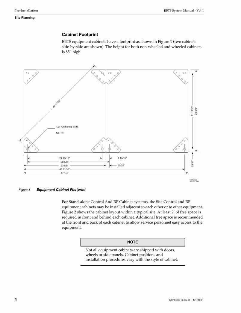
Pre-Installation EBTS System Manual - Vol 1
Site Planning
Cabinet Footprint
EBTS equipment cabinets have a footprint as shown in Figure 1 (two cabinets side-by-side are shown). The height for both non-wheeled and wheeled cabinets is 85” high.
For Stand-alone Control And RF Cabinet systems, the Site Control and RF equipment cabinets may be installed adjacent to each other or to other equipment. Figure 2 shows the cabinet layout within a typical site. At least 2’ of free space is required in front and behind each cabinet. Additional free space is recommended at the front and back of each cabinet to allow service personnel easy access to the equipment.
NOTE
Not all equipment cabinets are shipped with doors, wheels or side panels. Cabinet positions and installation procedures vary with the style of cabinet.
Figure 1 Equipment Cabinet Footprint
23 5/8"
21 13/16"
29/32"
23 5
/8"
21 1
3/16
"29
/32"
30 2
7/32
"
1/2" Anchoring Bolts
typ. (4)
1 13/16"
23 5/8"
46 11/32"
47 1/4"
EBTS008051094JNM
4 68P80801E35-O 4/1/2001

EBTS System Manual - Vol 1 Pre-Installation
Site Planning
Cabinet Floor Loading
Table 2 lists typical weight and floor loading information for various configurations of equipment cabinets.
Table 2 Equipment Cabinet Weight and Floor Loading
Configuration Weight(lbs)
Floor Loading(lbs/sq. ft.)
Control Cabinet 229 57
RF Cabinet with 1 BR 326 82
RF Cabinet with 2 BRs 414 104
RF Cabinet with 3 BRs 502 126
RF Cabinet with 4 BRs 590 148
RF Cabinet with 5 BRs 678 173
RF Cabinet with 6 BRs 766 193
RF Cabinet with 7 BRs 854 215
RF Cabinet with 8 BRs 942 237
Single Rack, Redundant Controller (SRRC)(combined control/RF cabinet)
606 156
Single Rack, Single Controller (SRSC)(combined control/RF/rectifier cabinet)
672 173
Cabinet Doors (each) 25 6
NOTE: There is a maximum of four doors per cabinet. The information in this table is typical and is not a guaranteed specification.
Figure 2 Typical Cabinet Layout
20'
10'
5'
2'
HVA
CH
VAC
BatteriesPowerSupplyCabinet
ControlCabinet
(CC)
RFCabinet
(RFC #1)
RFCabinet
(RFC #2)
RFCabinet
(RFC #3)
EBTS060052295JNM
Note: Double lines on above units indicate front of equipment.
68P80801E35-O 4/1/2001 5
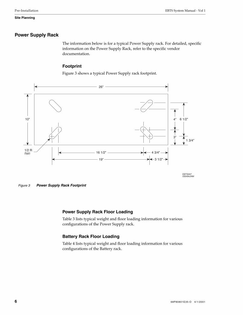
Pre-Installation EBTS System Manual - Vol 1
Site Planning
Power Supply Rack
The information below is for a typical Power Supply rack. For detailed, specific information on the Power Supply Rack, refer to the specific vendor documentation.
Footprint
Figure 3 shows a typical Power Supply rack footprint.
Power Supply Rack Floor Loading
Table 3 lists typical weight and floor loading information for various configurations of the Power Supply rack.
Battery Rack Floor Loading
Table 4 lists typical weight and floor loading information for various configurations of the Battery rack.
Figure 3 Power Supply Rack Footprint
16 1/2"
3"
4" 6 1/2"
26"
10"
19"
1/2 R(typ) 4 3/4"
3 1/2"
1 3/4"
EBTS007030494JNM
6 68P80801E35-O 4/1/2001

EBTS System Manual - Vol 1 Pre-Installation
Site Planning
Special Considerations
Breaker Panel Access
The National Electrical Code (NEC) requires a 36” clearance for electrical service access to all fuse panels, breaker panels, etc., and requires that all doors to this equipment open to at least 90˚.
Disabled Personnel
The customer is responsible for determining the applicable Americans with Disabilities Act (ADA) requirements that apply to the EBTS site. The ADA requires certain clearances for handicapped personnel.
One ADA requirement that should be considered is a 36” wide aisle for wheelchair-bound personnel. The aisle must include an adjacent “T” shaped area to allow room for maneuvering a wheelchair.
Table 3 Power Supply Rack Weight and Floor Loading
Configuration Weight(lbs)
Floor Loading(lbs/sq. ft.)
P.S. Rack with 1 rectifier 325 122
P.S. Rack with 2 rectifiers 346 130
P.S. Rack with 3 rectifiers 395 148
P.S. Rack with 4 rectifiers 416 156
P.S. Rack with 5 rectifiers 465 174
P.S. Rack with 6 rectifiers 486 182
NOTE: One rectifier is equivalent to 50 Amps. The information in this table is typical and is not a guaranteed specification.
Table 4 Battery Rack Weight and Floor Loading
Configuration Weight(lbs)
Floor Loading(lbs/sq. ft.)
Battery Rack with 1 tray 463 121
Battery Rack with 2 trays 876 229
Battery Rack with 3 trays 1289 337
Battery Rack with 4 trays 1707 447
NOTE: One tray contains four individual batteries. The information in this table is typical and is not a guaranteed specification.
68P80801E35-O 4/1/2001 7

Pre-Installation EBTS System Manual - Vol 1
Site Planning
Hazardous Materials and Equipment
NOTE
The following information is provided as an aid for the planning of an EBTS site. Compliance with all local, state, and federal regulations concerning the handling and use of hazardous materials and equipment is the sole responsibility of the customer and associated agents.
The proposed site must not have imminent hazards present in the form of hazardous materials (stored or spilled), harmful or dangerous conditions, or exposure to RF energy levels in excess of ANSI Occupational Guidelines.
If asbestos removal is required, it must be removed by a certified asbestos remover from the site improvement area or from places where it would be disturbed during site construction.
Floors containing asbestos may be left intact. However, drilling or penetration of the floor must be done in accordance with federal and state clean air guidelines. It is recommended that drilling be performed by a certified asbestos remover.
After any removal of asbestos, a certificate of air cleanliness for the site must be obtained from the contractor.
The standard battery system uses valve-regulated batteries designed for telecommunication applications. These batteries are also referred to as sealed or maintenance-free lead-acid batteries. Motorola recommends that these batteries be stored, transported, and installed by a certified hazardous material handler. Many regulatory agencies classify batteries as hazardous material. Special permits and safety equipment may be needed.
Seismically Active Areas
EBTS sites that are in seismically active areas may require additional bracing of the equipment cabinets. This manual does not contain specific procedures related to seismic bracing.
Telephone Company (Telco) Line Interface
Telco Surge Arrestor
A surge arrestor must be installed at the T1/E1 service entrance. The arrestor must be designed for operation with a T1/E1 telephone circuit. The arrestor must only be installed on the customer side of the T1/E1 service entrance. It should be wired per manufacturer instructions. Refer to Appendix B - Parts and Suppliers for the recommended surge arrestors.
8 68P80801E35-O 4/1/2001

EBTS System Manual - Vol 1 Pre-Installation
Site Planning
Telco Service Entrance
A rigid conduit sleeve must be installed to provide the service entrance into the site building. The conduit must be 2” in diameter and a PVC elbow should be attached (pointing down) on the outside end of the conduit. The conduit must be grounded in accordance with the Quality Standards-Fixed Network Equipment (FNE) Installation Manual (R56). Refer to the Manual Overview for information on obtaining the R56 manual.
Telco Backboard
A wall-mounted AC grade fire-rated plywood backboard (1/2”x4’x4’) must be provided within the site. Reserve a two square foot area on the Telco backboard for dedicated EBTS use.
A 120 VAC dual receptacle grounded outlet should be installed on or adjacent to the Telco backboard. This outlet can be used for accessories such as modems and other AC-powered devices. This may also be used as a general service outlet.
Environmental Considerations
Temperature Control
The environment in which the EBTS operates is an important consideration. The temperature should be regulated to ensure trouble-free operation. Lower temperatures will reduce battery capacity, but prolong life. Excessive temperatures result in generated heat that may reduce the lifespan of electronic equipment, and could cause permanent damage.
To prevent temperature problems, a Heating/Ventilation/Air-Conditioning (HVAC) system must be used. All HVAC systems should be thermostatically controlled. To prolong equipment life, the internal temperature of the EBTS site should be maintained at 78° F ±10° F (25.6° C ±5.5° C). The environmental equipment must be rated such that it is able to maintain the environment to meet the equipment heat dissipation values, which are given in British Thermal Units (BTUs).
BTUs can be figured by multiplying the power rating of the equipment by a factor of 3.414. For example; a Control Cabinet dissipates 300 Watts, which is equivalent to 1024.2 BTUs (300 x 3.414 = 1024.2). Refer to Table 5 for additional BTU information.
The EBTS equipment operates on a -48 VDC power system that typically includes a battery backup system. Should AC power be lost, the DC power system continues to supply the EBTS equipment with the necessary power. Because the EBTS remains operational during loss of AC power, heat is still generated by the equipment. Unless the site HVAC is on a backup system, the generated heat will affect the operation of the EBTS equipment. The operation of the EBTS equipment degrades when temperatures exceed 120˚ F (48.9˚ C).
68P80801E35-O 4/1/2001 9
Pre-Installation EBTS System Manual - Vol 1
Site Planning
For sites containing more than one-hour battery backup, the effect of generated heat should be considered. The HVAC system design should be evaluated to insure the proper operating environment is maintained in the event of AC power loss.
Redundant HVAC Systems
A redundant HVAC system may be installed, if necessary. It must be wired on a delayed circuit to prevent both HVAC systems from starting up simultaneously. The HVAC system should be capable of automatically switching between the heating and cooling modes in response to the thermostat. The controls must ensure that both modes never operate simultaneously.
Existing HVAC Systems
Existing building HVAC systems may be programmed to turn off during non-occupied hours. This type of HVAC system must be evaluated to insure that the site temperature is maintained within the range suitable for EBTS operation.
Humidity Control and Air Cleanliness
The relative humidity within the site should be less than 95% non-condensing. The site should also be a relatively dust-free environment. Proper measures should be taken to ensure the cleanliness of the site and that it remains relatively dust-free.
10 68P80801E35-O 4/1/2001

EBTS System Manual - Vol 1 Pre-Installation
Receipt of Equipment
Receipt of Equipment
Unpacking the Equipment
The EBTS equipment cabinets are packed with all modules intact. The shipping labels of the RF cabinets are numbered to identify their sector affiliation. This information is required when connecting the antennas on multiple sector sites. Save the labels from the protecting plastic wrap. Improper identification of the RF cabinet will result in frequencies being assigned to the wrong sectors.
WARNING!SOME POWER SUPPLY RACKS ARE NOT DESIGNED TO
STAND UNSECURED. IF THE RACK IS LEFT
UNATTENDED IN THE UPRIGHT POSITION, IT MAY TIP
CAUSING DAMAGE TO EQUIPMENT AND INJURY TO
PERSONNEL. DO NOT UNPACK THE POWER SUPPLY
RACK UNTIL IT IS READY FOR INSTALLATION.
Equipment Inspection
Inspection of the EBTS equipment must be performed as soon as all equipment is unpacked.
NOTE
If obvious damage has occurred to the shipping containers before unpacking, contact the shipping agent and ask that a representative of their company be present while the equipment is unpacked.
Observe guidelines for safe handling of electrostatic sensitive devices or equipment to prevent electrostatic discharge damage. An anti-static wrist strap is provided with the EBTS and should always be worn when handling any electrical component. Refer to the guidelines in the Manual Overview for additional information.
Inspect the following upon receipt of the EBTS:
Check for loose or damaged equipment.
Check all sides of each cabinet for dents, scratches, or other damage.
Check all cabinet wiring to insure connections are in place.
68P80801E35-O 4/1/2001 11

Pre-Installation EBTS System Manual - Vol 1
Receipt of Equipment
Check modules and boards for physical damage to controls or connectors.
Verify that ground straps are secure.
If any equipment is damaged, contact the shipping company immediately, then contact your Motorola representative.
Equipment Inventory
Check the EBTS equipment against the itemized packing list to insure that all equipment was received. If available, check the sales order with the packing list to account for all equipment ordered. Contact your Motorola representative to report missing items and for additional information.
12 68P80801E35-O 4/1/2001

EBTS System Manual - Vol 1 Pre-Installation
Electrical Requirements
Electrical Requirements
All electrical wiring for the EBTS site must meet the requirements of NEC and all applicable local codes.
AC Service
The DC power system typically operates from a 50-60 Hz AC service as listed below. (SRSC configuration operates from a 240 V, single-phase, 50/60 Hz service only.)
240/120 V single-phase, 3-wire
208/120 V three-phase, 4-wire
Equipment rooms constructed inside existing buildings that use higher voltage systems require a step-down transformer. A main disconnect switch located within the EBTS is recommended.
Service Amperage
When the HVAC is powered from the same panel or sub-panel as the DC power supply, 200 Amp service is recommended. When the HVAC is powered from a separate panel or sub-panel, 100 Amp service is recommended for the EBTS equipment. In stand-alone buildings or equipment shelters, a 200 Amp service entrance panel is also recommended.
The DC power system has normal loads and start-up loads, as does the HVAC. Both of these loads are dependent upon the number of BRs in the site and the size and condition of the battery system. The normal and start-up load of the Motorola offered power system is provided in Table 5 for several common EBTS configurations, using a two hour backup. These loads may differ for customer designed power systems.
Emergency Generator and Transfer Switch
Some sites may contain permanently installed emergency generators, however, most sites are equipped with connections for portable generators. Sites with permanently installed generators usually have an automatic transfer switch that transfers the AC service from the utility power to the generator after the generator has started. Sites with connections for a portable generator require a manual transfer switch and external connector. Refer to Appendix B - Parts and Suppliers for the recommended external connectors and wiring diagrams.
Generators and transfer switches must be capable of supporting the maximum load for the customer-defined service area of the generator. Start-up loads that include the HVAC and rectifiers must also be taken into consideration when selecting a generator size. Motorola offers several different generators for the EBTS site.
68P80801E35-O 4/1/2001 13

Pre-Installation EBTS System Manual - Vol 1
Electrical Requirements
In a shared site with multiple emergency power switches installed, each switch should be labeled with the associated system name with a weatherproof placard attached to or mounted next to the switch.
The EBTS site contains an Environmental Alarm System (EAS) that has eight dry contact closure outputs and 48 customer-defined inputs. The relay closures are controlled from the Operations and Maintenance Center (OMC) and one may be used as a remote start for permanent generators, if desired. The customer-defined inputs may be used to monitor permanent generator operation if desired. Refer to the Gen 3 SC Supplement to this manual for detailed information on alarm wiring.
Rectifier Drops
Where power supply cabinets are used, the conduit for the rectifier drops should be sized to support a maximum of six individual 30 Amp, 240 VAC rectifier
Table 5 Typical AC Power Loads (Imposed by DC Power System) (70 W BR)
Configuration(Total BRs on Site)
DC Load(Watts)
RectifiersRequired
AC Amps(nominal)
AC Amps(start-up)
Heat †(BTU)
(NOTE 2)
1 Sector - 2 Base Radios
1600 1 8 18 6,560
1 Sector - 5 Base Radios
3475 2 16 36 13,120
2 Sector - 4 Base Radios
2900 2 14 36 11,650
2 Sector - 10 Base Radios
6650 4 31 72 25,400
3 Sector - 6 Base Radios
4200 3 20 54 19,280
3 Sector - 12 Base Radios
7950 4 38 72 36,630
3 Sector - 24 Base Radios
15,450 8 75 140 71,200
SRRC (combined SC/RF equipment;4 BR)
3200 2 16 36 13,120
SRSC (combined SC/RF equipment/rectifier; 3 BR)
N/A N/A 15(NOTE 3)
19(NOTE 4)
11,270
NOTES:
1. The values contained in this table are to be used for planning purposes only. These values are typical and are not guaranteed equipment specifications.
2.BTU values listed in the Heat column are approximate and based on nominal AC Amps. Includes the heat generated by rectifiers and iDEN equipment.
3. SRSC operating at full equipment load; 220 VAC nominal line voltage.
4. SRSC battery charging at full capacity; 220 VAC nominal line voltage.
14 68P80801E35-O 4/1/2001

EBTS System Manual - Vol 1 Pre-Installation
Electrical Requirements
circuits. Wire drops to power the rectifiers must be installed per site plan and should reach within 5’ above the site floor. Mark these wire drops with the appropriate circuit breaker panel numbers. Terminate the drops in an AC electrical junction box.
Each rectifier requires a single wire drop. The standard configuration contains two rectifiers. Up to four additional rectifiers may be added at the customer’s option. Motorola recommends installation of four separate rectifier drops to facilitate future expansion requirements.
Surge Arrestors
A Motorola approved surge arrestor must be installed adjacent to the AC power panel. Very short wire lengths between the arrestor and the power panel are required for proper operation. Refer to Appendix B - Parts and Suppliers for the recommended surge arrestors.
For sites using a transfer switch, the arrestor must be installed on the panel side of the transfer switch. Additional arrestors may also be installed at the customer’s option on the line or generator side of the switch.
Motorola has developed a functional specification that is used to help select various surge arrestors. This specification is available to all customers and can be obtained by contacting your iDEN System Manager.
Power Panel
Motorola recommends that all EBTS sites use a standardized power panel including circuit breaker layout. Table 6 shows the layout recommended by Motorola. VACant space should be left to accommodate future requirements.
Table 6 Recommended Power Panel Layout
No. Amps Circuit Breaker Label No. Amps Circuit Breaker Label
1 20 Receptacle 1 (inside) 2 20 Receptacle 2 (inside)
3 20 Ceiling Light 440 HVAC
5 20 Smoke Detector 6
7 20 Outside GFI 830 Rectifier 3
930 Rectifier 1
10
11 1230 Rectifier 4
1330 Rectifier 2
14
15 1660 Surge Arrestor
17 20 Spare 18
NOTE: The rectifiers, HVAC, and surge arrestors are 2-pole breakers.
68P80801E35-O 4/1/2001 15

Pre-Installation EBTS System Manual - Vol 1
Electrical Requirements
48 VDC Power System (SCRF and SRRC Configurations)
The EBTS equipment operates on a DC power system that includes a -48 VDC battery system. Motorola offers a DC power system to complement the EBTS equipment. All references to the DC power system within this manual assume the use of the Motorola offered power system, however other systems may be used.
This manual only provides procedures for the -48 VDC battery system. If other DC power systems are used, then consult the manufacturer’s documentation supplied with the equipment.
DC Power Reference
The EBTS equipment operates from positive ground, 48 VDC power. Reference is made throughout this manual to the -48 VDC (hot) and the DC return power leads. The hot and return leads are kept isolated from chassis grounds in the equipment.
The positive (+) return lead is grounded at a single point on the rectifier load return bus. Table 7 shows the color coding for these wires.
Power Supply Rack
The Motorola offered Power Supply rack is field expandable from 50 to 300 Amps DC output in 50 Amp increments. Expansion can be accomplished without disrupting the operation of the EBTS. Customers may initially order the necessary amperage for the present site configuration, and if desired expand later as the need warrants. Contact your iDEN System Manager for information on expansion kits. The rectifier system also includes the necessary complement of circuit breakers and alarm wiring for the EBTS equipment.
The standard battery system utilizes from one to four trays of valve regulated, absorbed glass mat, lead-acid batteries in a 7’ relay rack. Battery capacity is increased by adding additional trays of batteries when and if needed. The single rack is designed to hold enough batteries for one-hour backup of all site configurations, and two-hour backup for up to nine BRs. Sites with extended battery backup times may require a different battery system. Contact your iDEN System Manager for additional information.
Sites with extended battery backup hours may require including the HVAC equipment on the battery back-up circuit, as well. Otherwise, an alternate method for maintaining site temperature must be used. iDEN equipment continues to generate heat when operating on battery backup which must somehow be dissipated.
Table 7 48VDC Power Bus Color Coding
Description BatteryConnection
Wire Color
-48 VDC (nominal) Negative (-) Red
DC Return Positive (+) Black
NOTE: The hot side is negative polarity (-) in the 48 VDC system power bus and the ground side is positive polarity (+).
16 68P80801E35-O 4/1/2001

EBTS System Manual - Vol 1 Pre-Installation
Electrical Requirements
Cabinet Requirements (SCRF and SRRC Configurations)
Proper sizing of the rectifiers and batteries is accomplished by the iDEN System Manager when the EBTS is ordered. The information in Table 8 is provided for customers that prefer to design a unique DC power system. This table lists the power system requirements of the Control and RF Cabinets.
Table 8 Typical Cabinet Power System Requirements
Configurations Requirement
DC Power System: †
Minimum
Maximum
-41 VDC
-60 VDC
Control Cabinet:
with standby Gen 3 SC
without standby Gen 3 SC
130 Watts
90 Watts
SCRF RF Cabinet/SRRC Cabinet:
without BRs
each additional BR (70 W P.A.)
50 Watts
625 Watts
† Voltage is measured at circuit breaker panel input of the equipment cabinets
68P80801E35-O 4/1/2001 17
Pre-Installation EBTS System Manual - Vol 1
Grounding Requirements
Grounding Requirements
The EBTS site must meet certain specifications for adequate protection from lightning induced transients. Proper ground installation methods are outlined in the Motorola Standards and Guidelines for Communications Sites (R56) 68P81089E50. Refer to the Manual Overview for information on obtaining the R56 manual.
Ground Rings
Separate ground rings should surround the site building and antenna tower. Ground rods (8’) should be driven into the ground at 10’ intervals for average soil. The two ground rings should be bonded together with one wire, buried at least 18” underground, or below frost level.
These ground rings are referred to as the exterior primary ground and must be at least #2 AWG tinned copper wire, solid or stranded. All connections to the rings should be made by exothermic welding. All exothermic welded connections should be treated with cold galvanizing spray.
Inspection wells should be provided, for access to the buried ground system to allow verification of ground resistance. The ground resistance should be less than 5Ω.
Tower Grounding
Ground each leg of the antenna tower with an 8’ ground rod driven near each leg. All ground connections to the antenna tower must be exothermically welded. Do not weld directly on tower structural members; weld only to provided tower grounding tabs or to tower feet.
NOTE
Make sure that welding ground connections to the antenna tower does not void the warranty of the tower.
Metal monopole towers require a minimum of three 8’ long ground rods to be driven into the ground, spaced approximately 10’ apart. These ground rods may be exothermically welded to the bottom portion of the mast itself, to the monopole footing, or to the provided grounding connection tabs.
18 68P80801E35-O 4/1/2001

EBTS System Manual - Vol 1 Pre-Installation
Grounding Requirements
Site Building and Equipment Grounding
On stand-alone site buildings, a PVC (typically 3/4”) conduit must be provided for the interior ground wire to exit the building. For site buildings with floors at ground level, the conduit must exit a side wall at a 45˚ angle or less. For buildings with space below the floors for a ground connection, the conduit may exit through the floor. In both cases, the location of the opening should be close to the master ground bar inside the building.
Use of metal conduit is discouraged as the conduit provides inductance to a surge, raising the impedance of the ground. If metal conduit is required by local building codes, both ends of the conduit must be bonded to the ground wire through the use of grounding clips or other suitable means to eliminate the inductance of the conduit.
Cabinet Grounding
Within the EBTS site, ground the cabinets with a single dedicated connection between each cabinet and the master ground bar. The connecting wire must be a #2 AWG green-insulated copper wire.
Use two-hole mounting lugs (and split ring lock washers when possible) with an anti-oxidant grease applied for interior grounding connections and exterior secondary grounding connections. If lock washers are used, they should be placed between the nut and the lug to ensure the mechanical integrity of the connection. The washer must not be secured between the lug and the surface to which it is connected. Painted connections must be scraped clean before applying the anti-oxidant grease and lug.
WARNING!NEVER USE A BARE OR DAMAGED WIRE FOR THE
CONNECTION OF CHASSIS GROUND OR OTHER
ELECTRICAL WIRING TO PREVENT DAMAGE TO
EQUIPMENT OR POTENTIAL INJURY TO PERSONNEL.
NOTE
Each EBTS cabinet frame must be connected to the site ground using a single dedicated ground wire, except for RF Cabinets containing cavity combining systems.
68P80801E35-O 4/1/2001 19

Pre-Installation EBTS System Manual - Vol 1
Grounding Requirements
The site ground wire should drop into the top of each cabinet and be connected to a single designated grounding stud. Single hole lugs (1/2” diameter) are used for these grounding connections. Connect the ground wires as follows:
On the Gen 3 SC Control Cabinet, the ground wire is mounted to one of the ground studs on the Junction Panel (rear of cabinet).
On equipment cabinets containing a duplexed RFDS, the ground wire is mounted to the studs located on each of the duplexers.
On equipment cabinets containing a cavity combining RFDS, two separate ground wires are required. One ground wire is connected to the cavity ground plate for cabinet grounding. Another ground wire is connected to one of the ground studs on the Junction Panel. This protects the tower top receive system.
WARNING!DO NOT DAISY-CHAIN MULTIPLE EQUIPMENT CABINET
GROUNDS USING A SINGLE GROUND WIRE. DOING SO
INCREASES THE OVERALL INDUCTANCE OF THE
GROUND WIRE WHICH CAN DISTRIBUTE SURGE
ENERGY AMONG THE CABINETS INSTEAD OF TO THE
MASTER GROUND BAR.
The EBTS equipment cabinets are classified as surge producers due to external coaxial cable connections. Surges from outside the site can enter the site grounding system via the coaxial cables. To prevent damage to the equipment, each cabinet must be connected to chassis ground through a minimum wire size of at least #2 AWG. Green insulated wire must be used to identify all ground wiring.
Cable Tray Grounding
The cable tray assembly must be designed and installed so that it does not come into contact with metal conduits, pipes, or other metal objects. The cable tray assembly must also be connected to the master ground bar through the use of a single dedicated wire. The connecting wire shall be a minimum size of #6 AWG green-insulated copper wire.
Any metal-to-metal joints on the cable tray assembly must be bonded together with a wire jumper to prevent electrical discontinuity, unless the tray connectors are specifically designed to insure continuity. Painted surfaces on the cable tray assembly must be scraped clean at the point where the jumper wire is attached to ensure a good electrical connection. Repaint cable tray assembly surfaces, if necessary.
20 68P80801E35-O 4/1/2001

EBTS System Manual - Vol 1 Pre-Installation
Grounding Requirements
Electrical System Grounding
The site electrical system should be connected to the internal ground bar by a single connection. This should be from the panel/sub-panel in the equipment room with a #2 AWG stranded green insulated wire. For sites with sub-panels, the utility green Multi-Grounded Neutral (MGN) wire may not be present. In this situation, an electrician may need to be consulted to extend the MGN from the service entrance to the sub-panel. If this is done in metal conduit, then grounding clips should be used at both ends of the conduit to minimize inductance.
If metal conduit is used for the electrical system, all connections must be bonded together through conduit compression or screw fitting designed for such purposes. The metal conduit system must not be in contact with other metal on the site including cable ladder or equipment cabinets to minimize ground loops and sharing of surge energy. Small pieces of rubber or other insulating material may be used on conduit clamps to eliminate any inadvertent connections.
WARNING!NEC PROHIBITS GROUNDING THE AC POWER SYSTEM
NEUTRAL (WHITE WIRE) ANYWHERE OTHER THAN AT
THE SERVICE ENTRANCE PANEL. HOWEVER,
GROUNDING OF THE MGN (GREEN WIRE) AT MULTIPLE
LOCATIONS IS ALLOWED.
ENSURE A GOOD CONNECTION BETWEEN THE
ELECTRICAL SYSTEM GROUND AND SITE GROUND TO
PREVENT EXCESSIVE VOLTAGE POTENTIAL BETWEEN
THE TWO GROUND SYSTEMS DURING LIGHTNING
STRIKES.
Power Supply and Battery Racks
The Power Supply rack (SCRF and SRRC configurations) and battery system rack should each be individually connected to the internal ground bar. Motorola recommends connecting the ground wire to one of the screws on the blank panel of the rack. Make sure that all paint is removed around the contact area to allow a good contact. Use a #2 AWG insulated grounding wire with a single hole lug to make the connections. The section on Installation provides a detailed procedure for grounding the Power Supply rack.
DC Power System Grounding
The DC power system is grounded only at a single point to prevent return current flow through ground connections and ground loops. A #6 AWG (or larger) insulated ground wire (green) with a double hole lug should be attached in one of
68P80801E35-O 4/1/2001 21

Pre-Installation EBTS System Manual - Vol 1
Grounding Requirements
the locations on the DC return bus of the Power Supply rack. This ground wire is also connected to the Master Ground Bar.
NOTE
The return bus on the Power Supply rack may be supported by red insulators. The color red in these insulators has no significance.
Telco Device Grounding
A single #6 AWG (or larger) insulated ground wire should be terminated on the Telco board for use by the various devices mounted to the board.
Miscellaneous Site Grounding
A #6 AWG, insulated ground wire may be installed within the site to connect the miscellaneous metal items (such as the door, door frame, HVAC grilles, etc.) that are not likely to be the source of electrical surges. All ground wiring should be routed near the ceiling, if possible.
One end of the ground wire must be connected to the Master Ground Bar. This connection bonds the remaining metal (conductive) items in the room with the ground system.
Ground Bars
There are two types of ground bars used in the EBTS site. Both ground bars should be mounted immediately below the antenna entry plate on both the inside and outside of the shelter wall. The ground bars must have direct wire connections to the site ground system.
Exterior Ground Bar
The Exterior Ground Bar (EGB) provides a convenient location to terminate coaxial grounding straps and grounding wires from exterior metal surfaces as they enter the site, including:
antenna feed line entrance plate
cable support
air conditioner housing
Master Ground Bar
The Master Ground Bar (MGB) is located inside the equipment room preferably underneath or near the cable entrance. Various metal structures within the site connect to the MGB, including the ground wires from:
22 68P80801E35-O 4/1/2001

EBTS System Manual - Vol 1 Pre-Installation
Grounding Requirements
EBTS equipment cabinets
power supply rack
battery system rack
DC power system return
Telco board
RF surge arrestors
electrical system
cable ladder/ceiling support system
other miscellaneous metal items and structures (door, louvers, etc.)
Motorola recommends the use of 1/4” thick copper ground bars with hole patterns to accept a minimum of 15 double hole lug connections (3/8” holes on 1” center). The ground lead from the ground bars to the ground rod system should be a minimum of #2 AWG. Both the internal and external ground bars must be connected together. This usually occurs when the internal ground wire exits the building and is tied into the ground rings with the external ground wire.
For sites which are part of an existing building, a connection to the building steel may be made in lieu of an underground ring. All other aspects of site interior grounding remain the same.
68P80801E35-O 4/1/2001 23

Pre-Installation EBTS System Manual - Vol 1
Antenna Installation
Antenna Installation
Antenna Feed Line Requirements
The transmission line entry for all antennas should be installed with a metal antenna entry plate external to the site building. All antenna feed line entry ports must be covered to prevent small animals or objects from entering. Transmission lines must be grounded to the exterior ground bar below the antenna feed line entry port using manufacturer approved grounding kits.
To reduce interference (intermodulation) problems, connectors on the transmit antenna lines must be gold or silver plated. The plating on the male/female connector combination must match on both connectors. For example, a male connector containing a gold plated center pin and silver plated outer conductor must match the female connector with a gold plated center pin and silver plated outer conductor.
All connectors at the antenna feed line entrance are Type N. Connector types at the antenna end may vary depending upon the antenna and jumper combinations selected by the customer. Contact your iDEN System Manager for additional information.
Antenna Feed Line Identification
All antenna feed lines should be marked appropriately to simplify connections to the proper EBTS equipment. Colored vinyl tape is recommended for use in identifying the antenna feed lines. Use 3M colored outdoor marking tape or a permanent, color-fast equivalent.
NOTE
The color coding schemes identified within this manual are a recommendation only. The purpose for identifying specific colors is an attempt to obtain uniformity between EBTS sites. Other color schemes may be used.
Table 9 shows how to identify the antenna feed lines for a typical duplexed RFDS. Table 10 shows how to identify the antenna feed lines for a typical cavity combining RFDS.
Be sure to identify the tower top amplifier test cable(s) in systems utilizing tower top amplifiers. Depending on the receive configuration, there could be as many as three individual test cables for the tower top amplifiers. Make sure that a unique color coding is used to identify these test cables.
24 68P80801E35-O 4/1/2001

EBTS System Manual - Vol 1 Pre-Installation
Antenna Installation
Antenna Surge Arrestors
All antenna feed lines should terminate with a suitable surge arrestor within 12” inside of the entry window. Each arrestor must connect to the master ground bar located below the entry plate. It is recommended that the arrestors be mounted to a mounting bracket to simplify grounding cable and installation. Refer to Appendix B - Parts and Suppliers for recommended surge arrestors and mounting brackets.
Table 9 Duplexed RFDS Antenna Identification (Typical)
Color Description
Red Base Radio Antenna 1 (receive/transmit)
Blue Base Radio Antenna 2 (receive/transmit)
Green Base Radio Antenna 3 (receive/transmit)
Brown Base Radio Antenna 4 (transmit; BR19/BR20)
Yellow Global Positioning System (GPS) Antenna
Orange Tower Top Amplifier Test Cables †
† The color of the tower top amplifier test cables are user defined. The routing of these test cables and the number of test cables installed are site dependent.
Table 10 Cavity Combining RFDS Antenna Identification (Typical)
Color Description
Red Base Radio Antenna 1 (receive)
Blue Base Radio Antenna 2 (receive)
Green Base Radio Antenna 3 (receive)
Brown Base Radio Antenna 4 (transmit)
Yellow Global Positioning System (GPS) Antenna
Orange Tower Top Amplifier Test Cables †
† The color of the tower top amplifier test cables are user defined. The routing of these test cables and the number of test cables installed are site dependent.
68P80801E35-O 4/1/2001 25
Pre-Installation EBTS System Manual - Vol 1
Antenna Installation
RF Antenna Planning
Antenna Identification
NOTE
The color coding schemes identified within this manual are a recommendation only. The purpose for identifying specific colors is an attempt to obtain uniformity between EBTS sites. Other color schemes may be used.
Within each sector is an antenna array containing up to three receive antennas. In a duplexed RFDS site, the transmit signals are present on the same receive antennas. In a cavity combining RFDS site, a separate transmit antenna is added to each sector. By referencing the antenna array with respect to a direct front view, these are:
RED represents the left-most antenna (#1)
BLUE represents the middle antenna (#2)
GREEN represents the right-most antenna (#3)
BROWN represents the transmit antenna (#4), if used
ORANGE represents the test port on the tower top amp (#5), if used
NOTE
Sectors containing two antennas typically have a left and right but no middle antenna.
Sector Identification
Typically, sectors are numbered 1, 2, or 3 in a clockwise manner with Sector 1 being the first sector from true north, 0 degrees. Figure 4 shows the recommended sector color coding. Table 11 identifies each of the antenna sectors. For example, a cable with three red bands indicates an antenna lead from Antenna 1 (left-most) within Sector 3.
Table 11 Sector Identification
Bands Description Coverage †
One band Sector 1 0˚ to 120˚
Two bands - same color Sector 2 120˚ to 240˚
Three bands - same color Sector 3 240˚ to 0˚
† Sector coverage assumes reference to true North, which is 0˚.
26 68P80801E35-O 4/1/2001
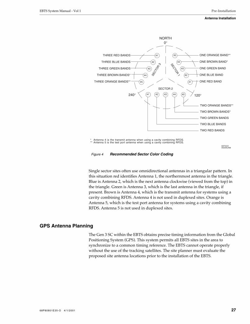
EBTS System Manual - Vol 1 Pre-Installation
Antenna Installation
Single sector sites often use omnidirectional antennas in a triangular pattern. In this situation red identifies Antenna 1, the northernmost antenna in the triangle. Blue is Antenna 2, which is the next antenna clockwise (viewed from the top) in the triangle. Green is Antenna 3, which is the last antenna in the triangle, if present. Brown is Antenna 4, which is the transmit antenna for systems using a cavity combining RFDS. Antenna 4 is not used in duplexed sites. Orange is Antenna 5, which is the test port antenna for systems using a cavity combining RFDS. Antenna 5 is not used in duplexed sites.
GPS Antenna Planning
The Gen 3 SC within the EBTS obtains precise timing information from the Global Positioning System (GPS). This system permits all EBTS sites in the area to synchronize to a common timing reference. The EBTS cannot operate properly without the use of the tracking satellites. The site planner must evaluate the proposed site antenna locations prior to the installation of the EBTS.
Figure 4 Recommended Sector Color Coding
SECTO
R 1SE
CTO
R 3
SECTOR 2
0°
120°240°
NORTH
EBTS031052295JNM
ONE BROWN BAND*
ONE GREEN BAND
ONE BLUE BAND
TWO GREEN BANDS
TWO BLUE BANDS
TWO RED BANDS
THREE GREEN BANDS
THREE BLUE BANDS
THREE RED BANDS ONE ORANGE BAND**
THREE BROWN BANDS*
TWO BROWN BANDS*
* Antenna 4 is the transmit antenna when using a cavity combining RFDS.** Antenna 5 is the test port antenna when using a cavity combining RFDS.
#1 #2 #3 #4
#4
#3
#2
#1
#3
#4
#5
TWO ORANGE BANDS**
#5
#2
ONE RED BAND#1THREE ORANGE BANDS** #5
68P80801E35-O 4/1/2001 27
Pre-Installation EBTS System Manual - Vol 1
Antenna Installation
GPS Antenna Evaluation
The Site Controller contains a GPS receiver that must locate and track at least four satellites during initial power-up. The four satellites are used to establish a three-dimensional fix (latitude, longitude, and altitude) for the site. This process takes approximately 13 to 25 minutes to complete.
Once the position of the site has been established, the corresponding data is stored in memory and normal operation resumes.
GPS Tracking Criteria
To allow an EBTS to successfully initialize, four satellites must be tracked
Once an EBTS is operating and the BRs have been keyed, site synchronization is maintained as long as at least one satellite is being tracked. However, to maintain maximum reliability, three satellites should be tracked at all times.
The EBTS must be capable of the following:
Tracking a minimum of four satellites during initial start-up or after loss of power to the SRI.
Tracking three satellites continuously for maximum reliability.
GPS Evaluation Kit
The Motorola GPS evaluation kit can be used to evaluate the site and antenna mounting location prior to site acceptance. Although many GPS receivers are available, the Motorola GPS evaluation kit includes the same receiver and antenna used in the EBTS. The data reported by this kit is the same as that used by the EBTS, if the antennas were installed in the test locations.
Refer to Appendix B - Parts and Suppliers for information on obtaining the Motorola GPS evaluation kit. The evaluation kit includes software programs and the instructions necessary to collect the necessary data in order to evaluate the site. The necessary data includes:
Number of visible satellites
Number of satellites being tracked
GPS Antenna Requirements
The two Global Positioning System (GPS) antennas should be mounted at least 10’ apart with an unrestricted aerial down view to within 10° of the horizon in all directions. This provides a degree of redundancy in case the antennas are damaged by falling objects or inadvertent shadowing.
The antennas must be mounted high enough to clear the peak of the EBTS site roof. For systems in the northern hemisphere, GPS antennas should be mounted so that a clear view of the southern sky is maintained. For systems in the southern hemisphere, GPS antennas should be mounted so that a clear view of the northern sky is maintained.
28 68P80801E35-O 4/1/2001
EBTS System Manual - Vol 1 Pre-Installation
Antenna Installation
Isolate the GPS antennas from RF interference by mounting the antennas at least 12’ horizontally from other transmitting antennas.
Adjacent structures, such as trees or buildings, are obstructions due to their wide, solid profiles. Mount the GPS antennas to clear these obstructions and provide a clear path. Adjacent antenna towers at the RF site which protrude into the required view have a minimal effect on GPS satellite reception and are not obstructions.
NOTE
The color coding schemes identified within this manual are a recommendation only. The purpose for identifying specific colors is an attempt to obtain uniformity between EBTS sites. Other color schemes may be used.
As mentioned in the RF Antenna Installation section, GPS antennas are color coded yellow. The same identification technique used for RF antennas is also used to identify the GPS antennas, refer to Table 12. Antenna 1 should always be the northern-most antenna.
GPS Antenna Line Loss
The maximum allowable line attenuation between the antenna and the Gen 3 SC is 6 dB. This includes a 4 dB foliage margin. Installations in which the antenna has an unobstructed view of the sky may have a maximum line attenuation of 10 dB. In a typical EBTS installation using 1/2” low density foam coaxial cable, the length of the cable run should never exceed 150’. This is sufficient for most installations.
When considering the use of larger cables, calculate the cable lengths allowing 4.5 dB of loss at 1.5 GHz. The remaining 1.5 dB of attenuation is provided by interior site cabling and connectors.
Another option is the use of in-line amplifiers to overcome excessive line loss. The in-line amplifiers are powered by the 5 VDC supplied by the GPS receiver and are inserted between the GPS antenna and the SRI, preferably near the antenna. Either the connector on the coaxial line must be changed to fit the amplifiers, or a short jumper cable field fabricated. Refer to Appendix B - Parts and Suppliers for information on the approved GPS in-line amplifiers.
Table 12 GPS Antenna Identification
Band Description
One yellow band GPS Antenna 1 (northern-most)
Two yellow bands GPS Antenna 2
68P80801E35-O 4/1/2001 29
Pre-Installation EBTS System Manual - Vol 1
Alarm Wiring
Alarm Wiring
Various alarms or sensors are installed within the EBTS site building. All alarm wiring terminates at the Environmental Alarm System (EAS) located within the Site Control Cabinet. The electrical contacts for the alarms must be dry contacts and remain normally closed (open on alarm). Refer to the Gen 3 SC Supplement to this manual for detailed alarm interconnect information.
Motorola recommends site installation of the following alarms:
Smoke detector (120 VAC)
Intrusion alarm
High temperature sensor
Low temperature sensor
The high temperature sensor should be capable of monitoring temperatures above 80˚ F (26.7° C). The low temperature sensor should be capable of monitoring temperatures below 70° F (21.1° C). Temperature sensors should be mounted to the Telco wiring board at a convenient height to facilitate the setting and inspection of the trigger points. Refer to Appendix B - Parts and Suppliers for recommended alarms.
Local codes may require an additional contact closure to deactivate the HVAC system and prevent circulation of smoke in the event of a fire. An additional smoke detector may be used to provide this contact. It can also be configured to trigger an external alarm, if required.
If a second alarm closure is used, it must be completely isolated from the dedicated EBTS smoke alarm circuit. Parallel connection of the HVAC controller through these contacts may damage the HVAC and EBTS equipment. This is because the HVAC low voltage controller typically has 5 VDC negative ground, which opposes the -48 VDC EBTS supply.
If specialized automatic fire suppression systems are installed within the site, water flow alarms or Halon release alarms may also be required. These systems may also have to be remotely monitored for unattended facilities. Check your local codes for additional information and requirements.
NOTE
The use of Halon within the United States of America is now prohibited. However, if a Halon fire suppression system is currently in use, there may be alarm requirements that have to be satisfied.
30 68P80801E35-O 4/1/2001

EBTS System Manual - Vol 1 Pre-Installation
Recommended Tools, Equipment, and Parts
Recommended Tools, Equipment, and Parts
Tables 13 through 15 list the tools, test equipment, and locally procured parts required to install the EBTS. The model numbers listed are recommended, but equivalent tools and equipment made by other manufacturers are acceptable. Refer to Appendix B - Parts and Suppliers for recommended tools, test equipment, and spare parts.
NOTE
When selecting tools and equipment, always choose those which have insulated grips and handles. This helps prevent potential injury resulting from electrical shock.
Recommended Tools
Table 13 lists the tools recommended for installation. These are not included as part of the EBTS shipment and must be procured locally. All model numbers are Motorola part numbers, unless noted otherwise.
Table 13 Recommended Tools for Installation
Tool Model/Type Supplier Description
Banding cutter n/a Locally Procured n/a
Cable Crimp Tool TBM5 S Thomas & Betts Crimping lugs on power cables
Calculator n/a Locally Procured n/a
Cart, Two-wheeled (luggage type)
6680387A47 Motorola Transportation of tools and test equipment
Cartridge Fuse Puller
34-002 Ideal Removing and installing cartridge-type fuses.
Circuit Cooler Spray
0180334B46 Motorola Low temperature alarm testing
Cellular tool kit RPX4286A Motorola Miscellaneous tools
Crimping Tool 8-pin modular cable
Locally Procured Customizing T1 connections
Digital Level 24" w/module Pro Smartlevel Antenna downtilt measurements
68P80801E35-O 4/1/2001 31

Pre-Installation EBTS System Manual - Vol 1
Recommended Tools, Equipment, and Parts
Driver Tools
2” hex to hex extension (2)
Locally Procured
n/a
6” hex to hex extension (2)
n/a
T10 TORX™ bit (APEX)
n/a
Long T10 TORX bit n/a
T15 TORX bit (APEX)
n/a
T20 TORX bit (APEX)
n/a
T25 TORX bit (APEX)
n/a
T30 TORX bit (APEX)
n/a
Electric Drill 0180371B44 Motorola Drilling holes
Electric Screwdriver(only 1 required)
RLN4053A/heavy duty
Motorola Tightening screws/nuts
RLN4051A/heavy duty (variable speed)
Motorola Tightening screws/nuts
0180320B28/light duty
Motorola Tightening screws/nuts
Flashlight, small n/a Locally Procured n/a
Hammer Drill RLN4315A Motorola Drilling concrete floor for mounting studs
Heat Gun 0180320B51 Motorola High temperature alarm testing
Hole Punch 1” Locally Procured Wiring 240 VAC to power supply cabinet
ISO T BNC n/a Locally Procured Used for tower top amp sensitivity testing
Knife, utility n/a Locally Procured n/a
Markers (2) n/a Locally Procured n/a
Nut driver, 3/16” n/a Locally Procured n/a
Nut driver, 10 mm n/a Locally Procured n/a
Pliers n/a Locally Procured n/a
Pliers, connector n/a Snap-on n/a
Pliers, needle nose n/a Locally Procured n/a
Screw driver, torque hand tool 5 in-lbs Ind Pneumatic n/a
Table 13 Recommended Tools for Installation (Continued)
Tool Model/Type Supplier Description
32 68P80801E35-O 4/1/2001

EBTS System Manual - Vol 1 Pre-Installation
Recommended Tools, Equipment, and Parts
Drives for torque screwdriver
1/4” drive, 7/16” deep socket
Ind Pneumatic
n/a
1/4” drive, 5/16” deep socket
n/a
1/4” drive, 3/16” socket
n/a
1/4” drive, 1” blade screwdriver
n/a
1/4” hex to 1/4” hex drive
n/a
Screwdrivers
#0 Phillips
Locally Procured
n/a
#2 Phillips n/a
3/16” blade n/a
#1 blade n/a
1/4” blade n/a
Step Ladder 7’ Locally Procured To gain access to cable tray assembly
Tarpaulin Approximately 8’ x 10’
Locally Procured Protect equipment during installation
Tie wrap gun n/a Locally Procured n/a
Tool Box n/a Locally Procured n/a
Torque wrenches
6680388A27 Motorola Tightening battery lug nuts
5/16” breaking type, 5 in-lbs
Locally Procured For SMA connectors
Drives for 5/16” torque wrench
6” extension, 3/8” drive
Snap-on
n/a
1” deep 6 point socket, 3/8” drive
n/a
5/8” deep socket, 3/8” drive
Ind Pneumatic
n/a
9/16” deep socket, 3/8” drive
n/a
1” deep socket, 3/8” drive
n/a
1/4” hex to 3/8” hex drive
n/a
Table 13 Recommended Tools for Installation (Continued)
Tool Model/Type Supplier Description
68P80801E35-O 4/1/2001 33

Pre-Installation EBTS System Manual - Vol 1
Recommended Tools, Equipment, and Parts
Recommended Test EquipmentTable 14 lists the recommended test equipment for installation. These are not included as part of the EBTS shipment and must be procured locally. All model numbers are Motorola part numbers, unless noted otherwise.
TORX driver with bits (handle storage)
n/a Locally Procured n/a
Tweezers n/a Locally Procured n/a
VACuum cleaner 0180382A11 Motorola General clean-up
Wire Cutters n/a Locally Procured Cutting power cables(#6 AWG to 250 MCM)
Wrenches, open end
3/8”Locally Procured
n/a
1-1/16” n/a
Wrist strap n/a Locally Procured n/a
Table 14 Recommended Test Equipment for Installation
Test Equipment Model/Type Supplier Description
Communication Software Procomm Plus(or equivalent)
DataStorm Host communication
Digital Multimeter
Fluke 77 Fluke DC measurements
R1037A Motorola DC measurements
R1073A Motorola DC measurements
File Compression Software
PKUnzip PKWare Compress/decompress files
Ground Resistance Ohmmeter
AEMC 3700 clamp-on ground tester
Locally Procured
Measure for adequate ground
RF Attenuators Refer to Appendix B
Protection for R2660 Analyzer and used with the EBTS equipment for RF attenuation
Service Computer Refer to Appendix B Local service terminal
Table 13 Recommended Tools for Installation (Continued)
Tool Model/Type Supplier Description
34 68P80801E35-O 4/1/2001
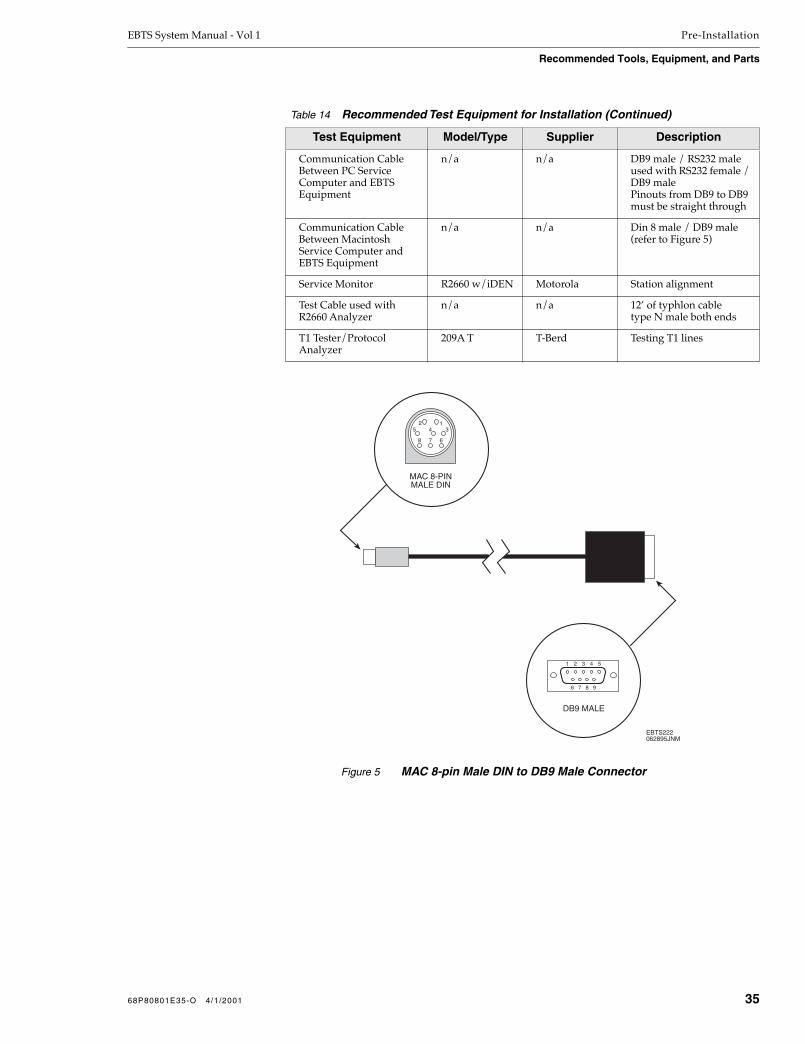
EBTS System Manual - Vol 1 Pre-Installation
Recommended Tools, Equipment, and Parts
Communication Cable Between PC Service Computer and EBTS Equipment
n/a n/a DB9 male / RS232 male used with RS232 female / DB9 malePinouts from DB9 to DB9 must be straight through
Communication Cable Between Macintosh Service Computer and EBTS Equipment
n/a n/a Din 8 male / DB9 male (refer to Figure 5)
Service Monitor R2660 w/iDEN Motorola Station alignment
Test Cable used with R2660 Analyzer
n/a n/a 12’ of typhlon cable type N male both ends
T1 Tester/Protocol Analyzer
209A T T-Berd Testing T1 lines
Table 14 Recommended Test Equipment for Installation (Continued)
Test Equipment Model/Type Supplier Description
MAC 8-PINMALE DIN
DB9 MALE
1 2 3 4 5
6 7 8 9
EBTS222062895JNM
13
678
52
4
Figure 5 MAC 8-pin Male DIN to DB9 Male Connector
68P80801E35-O 4/1/2001 35

Pre-Installation EBTS System Manual - Vol 1
Recommended Tools, Equipment, and Parts
Recommended Parts
Table 15 lists the recommended parts for installation. These are not included as part of the EBTS shipment and must be locally procured. All model numbers are Motorola part numbers, unless noted otherwise.
Table 15 Recommended Parts for Installation
Part Type/Size Supplier Where Used
Anchor Kit #02100-13 Hendry EBTS cabinet floor anchors
ColoredVinyl Tape
red, black, green, brown, yellow, and white
Locally Procured Wire identification
Grease anti-oxidant Locally Procured Battery terminal corrosion control
Lockwashers
split - 3/8” Locally Procured Breaker panel, Power Supply rack
split - 1/4” Locally Procured DC return bus, Power Supply rack
Lugs 2 hole 1" center various sizes
Locally Procured Battery connection; 3/8” bolt, 4/0 Cu
Lugs 2 hole 1" center Locally Procured DC return connection; 1/4” bolt, #6 Cu
Power Cables
#6 AWG stranded Cu (red and black)
Locally Procured Power supply wiring
4/0 stranded Cu (red and black)
Locally Procured Power supply wiring
Ground Cables
#2 AWG stranded Cu (green)
Locally Procured Cabinet grounding
#6 AWG stranded Cu (green)
Locally Procured Cabinet grounding
Refer to Appendix B - Parts and Suppliers for other cable sizes needed where equipment cabinets are not next to each other.
36 68P80801E35-O 4/1/2001

1 Installation
Overview
This section provides procedures required to permanently install the EBTS at the selected site. The section topics are listed in the following table.
NOTE
Unless otherwise noted, all data in this section applies equally to Stand-alone Control and RF Cabinet (SCRF), Single Rack, Redundant Controller (SRRC), and Single Rack, Single Controller (SRSC) EBTS configurations. Where differences exist, they are noted.
In this section, “equipment cabinet” similarly denotes an RF Cabinet (SCRF systems) or an SRRC or SRSC cabinet (unless specifically stated otherwise).
Section Page Description
Introduction 2 Provides general information for the installation procedures
EBTS Cabinet Installation
5 Describes installing wheeled and non-wheeled EBTS equipment cabinets
Power Supply Rack Installation
8 Provides general information regarding Power Supply Rack installation
Cabinet And Site Connections
9 Describes and lists general cabling procedures required in installing the EBTS
Intercabinet Cabling Procedures
13 Provides step-by-step procedures and diagrams for installing cabling between cabinets for systems using multiple cabinets
Cabinet-to-Site Cabling Procedures
38 Provides step-by-step procedures and diagrams for installing cabling between the EBTS and the site
68P80801E35-O 4/1/2001 1Network Solutions Sector
1301 E. Algonquin Road, Schaumburg, IL 60196

Installation EBTS System Manual - Vol 1
Introduction
Introduction
The procedures described in this section assume the field technician or installer has knowledge of the installation techniques contained in the Quality Standards Fixed Network Equipment - Installation Manual (R56).
NOTE
Prior to performing the installation procedures, prepare the site with all associated antennas, phone lines, and other related site equipment. This information is covered in the Pre-Installation section of this manual.
In an EBTS site, the term cabinet is used to refer to Fixed Network Equipment (FNE) mounted in different types of frames. It does not refer in any way to building electrical cabinets, outdoor utility cabinets, or some types of equipment shelters commonly known as cabinets.
The Site Control and equipment cabinets consist of Euroracks. These are shipped standard as an open frame with four corner posts with top and bottom assemblies to tie the posts together. Optional side panels and doors are available. The components of the Power Supply rack are shipped pre-assembled in open relay racks. The battery systems may be in a 7’ open rack or a custom designed enclosure.
Two terms are used interchangeably when discussing site configurations: cell and sector sites. Sector is commonly used when discussing antenna radiation patterns. Cell is commonly used when discussing configuration files. In an iDEN system, the two are synonymous. EBTS sites may be configured with one, two, or three sectors (cells). In this section of the manual, the term sector is used.
Single sector sites usually provide omni-directional RF coverage and are referred to as omni sites. Two or three sectored sites have different coverage patterns for the sectors and are referred to as sector sites. Each EBTS site requires a Gen 3 SC, whether in a separate stand-alone cabinet, or in the same cabinet as the Base Radios (single-cabinet system). Every sector within the EBTS site requires an RF Cabinet. For example, a three sector site contains a single Gen 3 SC and three RF Cabinets.
For a typical SCRF EBTS, a Site Control Cabinet and several RF Cabinets may be installed, depending on the configuration. An SRRC omni expansion EBTS may also use several cabinets. Table 1 lists the cabinet complements required for various systems that may use multiple cabinets.
Installation procedures (or appropriate references) for the Power Supply rack, batteries, and all associated cabling are also provided.
2 68P80801E35-O 4/1/2001

EBTS System Manual - Vol 1 Installation
Introduction
Table 1 Cabinet Complements For Various Systems
System/Site Type Cabinet Configuration
800 MHz GEN 4 DUPLEXED RFDS (STAND-ALONE CONTROL AND RF CABINET SYSTEM)
1-6 Channel Omni Expansion • one Gen Site Control Cabinet
• one Main GEN 4 Duplexed RF Cabinet
7-12 Channel Omni Expansion • one Site Control Cabinet
• one Main GEN 4 Duplexed RF Cabinet
• one Expansion Main GEN 4 Duplexed RF Cabinet
13-20 Channel Omni Expansion • one Site Control Cabinet
• one Main GEN 4 Duplexed RF Cabinet
• two Expansion Main GEN 4 Duplexed RF Cabinets
19-24 Channel Omni Expansion • one Site Control Cabinet
• one Main GEN 4 Duplexed RF Cabinet
• two Expansion Main GEN 4 Duplexed RF Cabinets
• one 19-24 Channel Expansion RF Cabinet
800 MHz GEN 4 DUPLEXED RFDS(SINGLE-RACK, REDUNDANT CONTROLLER (SRRC) SYSTEM)
1-10 Channel Omni Expansion • one SRRC primary cabinet
• one Expansion GEN 4 Duplexed RF Cabinet
11-16 Channel Omni Expansion • one SRRC primary cabinet
• two Expansion GEN 4 Duplexed RF Cabinet
17-22 Channel Omni Expansion • one SRRC primary cabinet
• two Expansion GEN 4 Duplexed RF Cabinet
• one 17-22 Channel Expansion RF Cabinet
900 MHz DUPLEXED RFDS
1-6 Channel Expansion • one Site Control Cabinet
• one Main RF Cabinet
7-12 Channel Expansion • one Site Control Cabinet
• one Main RF Cabinet
• one Expansion RF Cabinet
68P80801E35-O 4/1/2001 3

Installation EBTS System Manual - Vol 1
Introduction
800 MHz CAVITY COMBINING RFDS
1-5 Channel Omni Expansion • one Site Control Cabinet
• one Main Cavity RF Cabinet
6-10 Channel Omni Expansion • one Site Control Cabinet
• one Main Cavity RF Cabinet
• one Expansion Cavity RF Cabinet (without power monitor tray)
11-15 Channel Omni Expansion • one Site Control Cabinet
• one Main Cavity RF Cabinet
• one Expansion Cavity RF Cabinet (with power monitor tray)
• two Expansion Cavity RF Cabinet (without power monitor tray)
16-20 Channel Omni Expansion • one Site Control Cabinet
• one Main Cavity RF Cabinet
• one Expansion Cavity RF Cabinet (with power monitor tray)
• one Expansion Cavity RF Cabinet (without power monitor tray)
Sectored • one Site Control Cabinet
• three Main RF Cabinets
800 MHz DUPLEXED RFDS (0182020V06 and prior)
NOTE: 800 MHz Duplexed RFDS (0182020V06 and prior) is no longer available. It has been replaced by the 800 MHz GEN 4 Duplexed RFDS.
All information herein regarding 800 MHz Duplexed RFDS (0182020V06 and prior) is for reference only.
1-4 Channel Duplex Hybrid Expansion • one Site Control Cabinet
• one Main Duplexed RF Cabinet
5-8 Channel Duplex Hybrid Expansion • one Site Control Cabinet
• one Main Duplexed RF Cabinet
• one Expansion Duplexed RF Cabinet
9-12 Channel Duplex Hybrid Expansion • one Site Control Cabinet
• one Main Duplexed RF Cabinet
• two Expansion Duplexed RF Cabinets
Sectored • one Site Control Cabinet
• three Main Duplexed RF Cabinets
Table 1 Cabinet Complements For Various Systems (Continued)
System/Site Type Cabinet Configuration
4 68P80801E35-O 4/1/2001

EBTS System Manual - Vol 1 Installation
EBTS Cabinet Installation
EBTS Cabinet Installation
This sub-section provides procedures for permanently mounting the EBTS equipment cabinets within a site.
Refer to the manufacturer’s installation manual for installation information for the power supply rack and battery rack.
Cabinet Bracing Considerations
EBTS cabinets are self-supporting structures. The cabinets require additional bracing during shipment of prefabricated sites.
In areas subject to seismic activity, additional bracing of the cabinet may be required to prevent it from tipping. However, the bracing hardware must be locally procured. There are no specific procedures within this manual for bracing cabinets in active seismic areas.
WARNING!EQUIPMENT CABINETS ARE HEAVY AND MAY TIP. USE
EXTREME CAUTION WHEN MOVING. LIFT FROM TOP
EYE BOLTS WITH APPROPRIATE APPARATUS OR
SECURE CABINET FROM TIPPING IF LIFTING FROM
BOTTOM. FAILURE TO DO SO COULD RESULT IN
DEATH OR SERIOUS INJURY OR EQUIPMENT DAMAGE.
Cabling Considerations
On installations consisting of multiple cabinets, intercabinet cables used in the EBTS installation are manufactured in predetermined lengths. The length of the cables restricts the height of the site cable tray to no more than 6” above the cabinets. This also restricts the spacing between cabinets to no more than 5”.
The intercabinet cabling requires a cabinet layout configuration similar toFigure 1. If the site cannot accommodate one of these layouts, the intercabinet cables shipped with the EBTS may not be long enough. Refer to Appendix B - Parts and Suppliers for information on manufacturing custom cables.
68P80801E35-O 4/1/2001 5

Installation EBTS System Manual - Vol 1
EBTS Cabinet Installation
Access Considerations
Allow at least 2’ of floor space in front and behind the cabinets to permit access during installation. Although most maintenance is performed from the front of the equipment cabinets, access to the rear is required for expansion, cabling, and antenna connections.
Cabinet Position Considerations
Sector Identification
The location of each base radio within the RF Cabinets is identified in the software. The identification includes the RF cabinet the BR is located in, and the BR’s position within the RF Cabinet. This is an important consideration for installation and cabling.
Typically, the BRs in RF Cabinet 1 are programmed with information relating to a sector 1. Each sector is dedicated to a specific RF Cabinet. Antennas from each sector must be connected to the appropriate RF Cabinet.
The RF Cabinet number is identified on the RF Cabinet shipping label. Make sure that all cabinets are positioned properly before performing the following procedures so that the cabinet and sector numbers match. Figure 1 shows a typical cabinet layout.
Cabinets
The following procedures describe how to mount cabinets in an EBTS site building. Read all of the procedures carefully to ensure a quality installation.
EBTS cabinets must be secured to the floor for optimum stability. This includes the Power Supply rack. Since the cabinets are quite heavy, this procedure is written so that each cabinet is moved only once.
Figure 1 Typical EBTS Cabinet Layout
20'
10'
5'
2'
HVA
CH
VAC
BatteriesPowerSupplyCabinet
ControlCabinet
(CC)
RFCabinet
(RFC #1)
RFCabinet
(RFC #2)
RFCabinet
(RFC #3)
EBTS060052295JNM
Note: Double lines on above units indicate front of equipment.
6 68P80801E35-O 4/1/2001

EBTS System Manual - Vol 1 Installation
EBTS Cabinet Installation
Motorola recommends installing the first cabinet at the far end of the row, and then installing adjacent cabinets until the row is completed. If the Power Supply rack and batteries have been previously installed, mount the Site Control Cabinet first, followed by the RF Cabinet(s) in the same manner.
Perform the following steps to properly install the EBTS cabinets within the site building:
1. Measure the mounting location for the first cabinet in the row.
Refer to the cabinet footprint(s) located in the Pre-Installation section of this manual.
2. Carefully mark the mounting holes with a pencil, as indicated on the appropriate cabinet footprint.
3. Drill the marked mounting holes to the appropriate depth of the mounting hardware with a hammer drill and bit.
Refer to Appendix B - Parts and Suppliers for recommended mounting hardware.
4. Insert an anchor into the drilled hole.
If necessary, tap the anchor into place using a hammer.
5. Remove the four screws securing the bottom kick panel to the front and back of the cabinet.
Remove the kick panel and set aside during installation.
WARNING!EQUIPMENT CABINETS ARE HEAVY AND MAY TIP. USE
EXTREME CAUTION WHEN MOVING. LIFT FROM TOP
EYE BOLTS WITH APPROPRIATE APPARATUS OR
SECURE CABINET FROM TIPPING IF LIFTING FROM
BOTTOM. FAILURE TO DO SO COULD RESULT IN
DEATH OR SERIOUS INJURY OR EQUIPMENT DAMAGE.
6. Carefully move the cabinet into the position indicated by the holes in the floor.
Adjust and level the cabinet as necessary to position the cabinet mounting holes with the pre-drilled holes.
7. Secure the cabinet to the site floor with the locally procured mounting hardware.
8. If required, connect adjacent cabinets to each other using the ganging hardware (kit no. THN6718A).
68P80801E35-O 4/1/2001 7

Installation EBTS System Manual - Vol 1
Power Supply Rack Installation
Power Supply Rack Installation
SCRF and SRRC systems require installation of a power supply rack, which is separate from the EBTS.
For detailed instructions on installing the iDEN Power Supply rack, please refer to the manual supplied with the Power Supply rack.
8 68P80801E35-O 4/1/2001

EBTS System Manual - Vol 1 Installation
Cabinet And Site Connections
Cabinet And Site Connections
Cabinet and site connections consist of the cabling to be installed between cabinets (intercabinet cabling) and cabling to be installed between the EBTS and the site (cabinet-to-site cabling).
EBTS Junction Panels
Most of the intercabinet and site-to-cabinet cabling is connected via the Junction Panel located at the top rear of each equipment cabinet. Figures 2 and 4 show the different types of junction panels.
The Junction Panel is accessed from the rear of the cabinet. All intercabinet cabling runs up and out the top of each cable tray assembly. The OUT connection for each cable has been connected by the factory. Installation of intercabinet cabling is completed by connecting the free end of the cable to the appropriate IN connector on adjacent cabinets.
Cabling connections utilizing connecting points other than the Junction Panel are described as applicable in the various procedures that follow.
Figure 2 Typical Junction Panel (Rear View)
Figure 3 Typical Junction Panel for Expansion RF Systems (Rear View)
EBTS315A122796JNM
IN OUTETHERNET 5 MHz/1PPS
ISOLATED GROUND
RX3 RX2 RX1GPS BGPS ABMR ANTTX OUT
ALARMIN OUT ETHERNET(GROUNDED)
NOTE: THE EXPANSION JUNCTION PANEL IS NOT USED IN GEN 4 SYSTEMS.
MSER011051299JNM
TRAY 1EXP 1
TRAY 1EXP 2
TRAY 1EXP 3
TRAY 2EXP 1
TRAY 2EXP 2
TRAY 2EXP 3
TRAY 3EXP 1
TRAY 3EXP 2
TRAY 3EXP 3
BRANCH 3SECTOR 3
BRANCH 3SECTOR 2
BRANCH 3SECTOR 1
BRANCH 2SECTOR 3
BRANCH 2SECTOR 2
BRANCH 2SECTOR 1
BRANCH 1SECTOR 3
BRANCH 1SECTOR 2
BRANCH 1SECTOR 1
68P80801E35-O 4/1/2001 9

Installation EBTS System Manual - Vol 1
Cabinet And Site Connections
Figure 4
Typical Junction Panel for Control Cabinets
Cabling Part Numbers And Quantities
The required cabling part numbers and quantities are specified in the procedures that follow, or in the section of this manual that individually covers the particular type of system being installed, as applicable.
Intercabinet Cabling
Intercabinet cabling describes the cabling to be installed between equipment cabinets and the power supply rack in SCRF and SRRC systems. Perform each of the individual intercabinet cabling procedures listed in the table below (as applicable) for the particular system being installed.
When all applicable intercabinet cabling procedures have been performed, proceed to Cabinet-to-Site Cabling Procedures.
NOTE
Since the SRSC system uses only one cabinet, intercabinet cabling is not required for an SRSC system. Omit Intercabinet Cabling Procedures and proceed directly to Cabinet-to-Site Cabling
Procedures.
EBTS315011101JNM
GPS BGPS AOUT 3 OUT 2 OUT 1 10B2-3 10B2-2 10B2-1 TX OUT RX2RX3 RX1
5MHz/1PPS ETHERNET
SITE GROUND SITE GROUND
10 68P80801E35-O 4/1/2001

EBTS System Manual - Vol 1 Installation
Cabinet And Site Connections
Procedure Page Description
5 MHz/1 PPS Intercabinet Cabling
13 Connection of the system 5 MHz/1 PPS timing reference signal provided by the Gen 3 SC for the Base Radios
Ethernet Intercabinet Cabling
21 Connection of EBTS Ethernet between cabinets
Alarm Intercabinet Cabling
26 Connection of cabinet alarm connections between cabinets
Primary Control Channel Redundancy Intercabinet Cabling
33 Connection of the Primary Control Channel redundancy control cable from the Gen 3 SC to the RF Cabinet
Power Supply Rack-to-EBTS Power (-48 VDC) Connections
34 Connection of -48 VDC power wiring from Power Supply rack to equipment cabinets
68P80801E35-O 4/1/2001 11

Installation EBTS System Manual - Vol 1
Cabinet And Site Connections
Cabinet-to-Site Cabling
Cabinet-to-site cabling describes the cabling to be installed between the EBTS equipment cabinet(s) and the site for all systems. Perform each of the individual cabling procedures listed in the table below (as applicable) for the particular system being installed.
Procedure Page Description
AC Mains Connection (SRSC Systems Only)
38 Connection of SRSC cabinet to AC mains
Battery Backup Connections (SRSC Systems Only)
41 Connection of SRSC cabinet to battery backup rack
Equipment Cabinet Ground Connections
44 Connection of equipment cabinet grounds
Base Radio Antenna Connections
50 Connection of site Base Radio antennas to EBTS
GPS Antenna Connections
60 Connection of site GPS antenna(s) to EBTS (reference to procedure)
Alarm Intercabinet Cabling
26 Connection of site and Power Supply rack alarm connections to the EBTS (reference to procedure)
T1/E1 Cabling 60 Connection of site T1/E1 line to the EBTS (reference to procedure)
12 68P80801E35-O 4/1/2001

EBTS System Manual - Vol 1 Installation
Intercabinet Cabling Procedures
Intercabinet Cabling Procedures
NOTE
Since the SRSC system uses only one cabinet, intercabinet cabling is not required for an SRSC system. Omit Intercabinet Cabling Procedures and proceed directly to Cabinet-to-Site Cabling
Procedures.
Perform the following intercabinet cabling procedures (as applicable) for the system being installed.
5 MHz/1 PPS Intercabinet Cabling
NOTE
A powered-down BR connected to the 5 MHz/1 PPS system can degrade the 5 MHz/1 PPS signal for the other BRs, possibly causing malfunctions.
Before powering-down a BR, always first disconnect the BR from the 5 MHz/1 PPS system. Make certain powered-down BRs are not connected to the 5 MHz/1 PPS system. (5 MHz/1 PPS “T” connections at a powered-down BR can be left open; termination at
these points is not required.)
5 MHz/1 PPS intercabling is the 5 MHz/1 PPS cabling from the cabinet containing the site controller to the RF Cabinet(s). Figures 5 through 12 show the required intercabling for various EBTS site configurations. Table 2 correlates the specific types of systems and sites to Figures 5 through 12.
Intercabinet Connections
The 5 MHz/1 PPS signal originates in the site controller. All 5 MHz/1 PPS connections between the Site Controller and the RF Cabinet(s) are made on the junction panel of the Site Control and RF Cabinets.
The site controller has three identical buffered outputs available at connectors
SITE REF OUT 1, SITE REF OUT 2
and
SITE REF OUT 3
.
The
SITE REF
OUT
connectors should be utilized in a manner that distributes the BR load evenly between the three outputs.
68P80801E35-O 4/1/2001 13

Installation EBTS System Manual - Vol 1
Intercabinet Cabling Procedures
To properly distribute the BR load and ensure site reliability in the event of a failure, follow the general guidelines specified below:
Distribute the load as evenly as possible between the three
SITE REF OUT
output connectors.
As with all 5 MHz/1 PPS cabling, the far-end of each daisy-chain must be terminated with the specified 50
Ω
load.
In sectored sites with multiple RF Cabinets serving a single sector, do not drive all cabinets within a single sector from the same output.
The following examples illustrate possible RF Cabinet 5 MHz/1 PPS intercabling that balances the BR load and provides site reference output redundancy within a sector.
Example 1 - Assume a 24-BR, three-sector site consisting of the following arrangement:
12 BRs in Sector 1
8 BRs in Sector 2
4 BRs in Sector 3
The table below shows a proper distribution of the site reference outputs to the RF Cabinets (RFCs).
Note that in the above example, each output drives 8 BRs, while utilizing all three outputs within sector 1.
Example 2 - Assume a 16-BR, two-sector site with the following arrangement:
8 BRs in Sector 1
8 BRs in Sector 2
The table below shows a proper distribution of the site reference outputs to the RFCs.
Note that in the above example, each output drives eight BRs, while utilizing two different outputs within a given sector.
Site Ref Output
Sector 1(12 BRs)
Sector 2(8 BRs)
Sector 3(4 BRs)
1 RFC 1 (4 BRs) RFC 4 (4 BRs)
2 RFC 2 (4 BRs) RFC 6 (4 BRs)
3 RFC 3 (4 BRs) RFC 5 (4 BRs)
Site Ref Output
Sector 1(8 BRs)
Sector 2(8 BRs)
1 RFC 1 (4 BRs) RFC 3 (4 BRs)
2 RFC 2 (4 BRs) RFC 4 (4 BRs)
14 68P80801E35-O 4/1/2001

EBTS System Manual - Vol 1 Installation
Intercabinet Cabling Procedures
Example 3 - Assume a 20-BR omni site with four RFCs, each containing five BRs. The table below shows a proper distribution of the site reference outputs to the RFCs.
Note that in the above example, each output drives 10 BRs.
5 MHz/1 PPS Cabling Procedure
Noting the general guidelines discussed above, perform 5 MHz/1 PPS cabling between cabinets as follows:
1.
On the cabinet that contains the site controller, connect cable (PN 0112004Z29) to the
5 MHz/1 PPS OUT 1
connector on the junction panel. For sites with more than 15 channels, connect an additional cable (PN 0112004Z29) to the
5 MHz/1 PPS OUT 2
connector on the junction panel.
Connect free end of cable(s) to
5 MHz/1 PPS IN
connector on RF Cabinet(s).
2.
Starting at the first RF Cabinet, daisy-chain connect cables (PN 0112004Z29) from the
5 MHz/1 PPS OUT
connectors to the
5 MHz/1 PPS IN
connectors on each cabinet junction panel in accordance with Table 2 and Figures through 9, as applicable.
3.
Connect a 50
Ω
BNC Terminator (PN 0909906D01) to the
5 MHz/1 PPS OUT
connector on the last RF Cabinet of each daisy-chain in the configuration. (Systems using
both
the OUT 1 and OUT 2 site reference outputs will have
two
50
Ω
end terminations.)
4.
Proceed to Ethernet Intercabinet Cabling.
Output Omni 20
1 RFC 1 (5 BRs)
RFC 2 (5 BRs)
2 RFC 3 (5 BRs)
RFC 4 (5 BRs)
68P80801E35-O 4/1/2001 15

Installation EBTS System Manual - Vol 1
Intercabinet Cabling Procedures
Table 2
5 MHz/1 PPS Intercabinet Cabling
System/Site Type Cabinet Configuration Perform Cabling As Shown In:
800 MHz GEN 4 DUPLEXED (STAND-ALONE CONTROL AND RF CABINET) / 900 MHz RFDS
1-6 Channel Omni 1 Main RF Cabinet Figure 5
7-12 Channel Omni Expansion 1 Main RF Cabinet
1 Expansion RF Cabinet
Figure 6
13-20 Channel Omni Expansion* 1 Main RF Cabinet
2 Expansion RF Cabinets
Figure 7or
Figure 8
19-24 Channel Omni Expansion* 1 Main RF Cabinet
3 Expansion RF Cabinets
Figure 8
800 MHz GEN 4 RFDS SRRC EXPANSION SYSTEMS
4-10 Channel Omni Expansion 1 SRRC Primary Cabinet
1 Expansion RF Cabinet
Figure 10
11-16 Channel Omni Expansion* 1 SRRC Primary Cabinet
2 Expansion RF Cabinet
Figure 11or
Figure 12
17-22 Channel Omni Expansion* 1 SRRC Primary Cabinet
3 Expansion RF Cabinet
Figure 12
CAVITY COMBINING RFDS
1-5 Channel Omni 1 Main RF Cabinet Figure 5
6-10 Channel Omni Expansion 1 Main RF Cabinet
1 Expansion RF Cabinet
Figure 6
11-15 Channel Omni Expansion 1 Main RF Cabinet
2 Expansion RF Cabinets
Figure 7
16-20 Channel Omni Expansion* 1 Main RF Cabinet
3 Expansion RF Cabinets
Figure 8
Sectored 3 Main RF Cabinets Figure 9
* Systems using more than 15 channels require High-Capacity Controllers utilizing multiple 5MHz/1PPS outputs.
16 68P80801E35-O 4/1/2001

EBTS System Manual - Vol 1 Installation
Intercabinet Cabling Procedures
800 MHz DUPLEXED RFDS (0182020V06 and prior)
NOTE:
800 MHz Duplexed RFDS (0182020V06 and prior) is no longer available. It has been replaced by the 800 MHz GEN 4 Duplexed RFDS.
All information herein regarding 800 MHz Duplexed RFDS (0182020V06 and prior) is for reference only.
1-5 Channel Duplex Hybrid Expansion 1 Site Control Cabinet
1 Main Duplexed RF Cabinet
Figure 5
5-8 Channel Duplex Hybrid Expansion 1 Site Control Cabinet
1 Main Duplexed RF Cabinet
1 Expansion Duplexed RF Cabinet
Figure 6
9-12 Channel Duplex Hybrid Expansion 1 Site Control Cabinet
1 Main Duplexed RF Cabinet
2 Expansion Duplexed RF Cabinets
Figure 7
Sectored 1 Site Control Cabinet
3 Main Duplexed RF Cabinets
Figure 9
* Systems using more than 15 channels require High-Capacity Cabinet utilizing multiple 5MHz/1PPS outputs.
Table 2
5 MHz/1 PPS Intercabinet Cabling (Continued)
System/Site Type Cabinet Configuration Perform Cabling As Shown In:
68P80801E35-O 4/1/2001 17

Installation EBTS System Manual - Vol 1
Intercabinet Cabling Procedures
Figure 5
5 MHZ/1 PPS Connections for Single RF Cabinet Omni Sites
Figure 6
5 MHz/ 1PPS Connections for 2 RF Cabinet Omni Expansion Sites
Figure 7
5 MHz/1 PPS Connections for 3 RF Cabinet Omni Expansion Sites (15 or fewer Channels)
EBTS301040201JNM
0909906D01Terminator
0112004Z29
CABINET w/ GEN 3 SC RF CABINET #1
IN OUTETHERNET 5 MHz/1PPS
ISOLATED GROUND
RX3 RX2 RX1GPS BGPS ABMR ANTTX OUT
ALARMIN OUT ETHERNET(GROUNDED)
GPS BGPS AOUT 3 OUT 2 OUT 1 10B2-3 10B2-2 10B2-1 TX OUT RX2RX3 RX1
5MHz/1PPS ETHERNET
50ΩTERMINATIONS
GPS BGPS AOUT 3 OUT 2 OUT 1 10B2-3 10B2-2 10B2-1 TX OUT RX2RX3 RX1
5MHz/1PPS ETHERNET
0112004Z29
EBTS302040201JNM
CABINET w/ GEN 3 SC EXPANSION RF CABINET
0909906D01Terminator
0112004Z29
MAIN RF CABINET
IN OUTETHERNET 5 MHz/1PPS
ISOLATED GROUND
RX3 RX2 RX1GPS BGPS ABMR ANTTX OUT
ALARMIN OUT ETHERNET(GROUNDED)
IN OUTETHERNET 5 MHz/1PPS
ISOLATED GROUND
RX3 RX2 RX1GPS BGPS ABMR ANTTX OUT
ALARMIN OUT ETHERNET(GROUNDED)
50ΩTERMINATIONS
0112004Z29 0112004Z29
EBTS303040201JNM
CABINET w/ GEN 3 SC
0909906D01Terminator
0112004Z29
MAINRF CABINET
EXPANSIONRF CABINET #1
EXPANSIONRF CABINET #2
IN OUTETHERNET 5 MHz/1PPS
ISOLATED GROUND
RX3 RX2 RX1GPS BGPS ABMR ANTTX OUT
ALARMIN OUT ETHERNET(GROUNDED)
IN OUTETHERNET 5 MHz/1PPS
ISOLATED GROUND
RX3 RX2 RX1GPS BGPS ABMR ANTTX OUT
ALARMIN OUT ETHERNET(GROUNDED)
IN OUTETHERNET 5 MHz/1PPS
ISOLATED GROUND
RX3 RX2 RX1GPS BGPS ABMR ANTTX OUT
ALARMIN OUT ETHERNET(GROUNDED)
GPS BGPS AOUT 3 OUT 2 OUT 1 10B2-3 10B2-2 10B2-1 TX OUT RX2RX3 RX1
5MHz/1PPS ETHERNET
50ΩTERMINATIONS
18 68P80801E35-O 4/1/2001
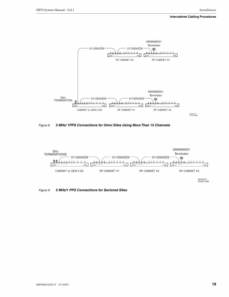
EBTS System Manual - Vol 1 Installation
Intercabinet Cabling Procedures
Figure 8
5 MHz/ 1PPS Connections for Omni Sites Using More Than 15 Channels
Figure 9
5 MHz/1 PPS Connections for Sectored Sites
EBTS374011101JNM
0909906D01Terminator
0112004Z29
CABINET w/ GEN 3 SC RF CABINET #1 RF CABINET #3
0112004Z29
0909906D01Terminator
0112004Z29
RF CABINET #2 RF CABINET #4
0112004Z29
IN OUTETHERNET 5 MHz/1PPS
ISOLATED GROUND
RX3 RX2 RX1GPS BGPS ABMR ANTTX OUT
ALARMIN OUT ETHERNET(GROUNDED)
IN OUTETHERNET 5 MHz/1PPS
ISOLATED GROUND
RX3 RX2 RX1GPS BGPS ABMR ANTTX OUT
ALARMIN OUT ETHERNET(GROUNDED)
IN OUTETHERNET 5 MHz/1PPS
ISOLATED GROUND
RX3 RX2 RX1GPS BGPS ABMR ANTTX OUT
ALARMIN OUT ETHERNET(GROUNDED)
IN OUTETHERNET 5 MHz/1PPS
ISOLATED GROUND
RX3 RX2 RX1GPS BGPS ABMR ANTTX OUT
ALARMIN OUT ETHERNET(GROUNDED)
GPS BGPS AOUT 3 OUT 2 OUT 1 10B2-3 10B2-2 10B2-1 TX OUT RX2RX3 RX1
5MHz/1PPS ETHERNET
50ΩTERMINATION
0112004Z29 0112004Z29
EBTS373040201JNM
CABINET w/ GEN 3 SC
0909906D01Terminator
0112004Z29
RF CABINET #1 RF CABINET #2 RF CABINET #3
IN OUTETHERNET 5 MHz/1PPS
ISOLATED GROUND
RX3 RX2 RX1GPS BGPS ABMR ANTTX OUT
ALARMIN OUT ETHERNET(GROUNDED)
IN OUTETHERNET 5 MHz/1PPS
ISOLATED GROUND
RX3 RX2 RX1GPS BGPS ABMR ANTTX OUT
ALARMIN OUT ETHERNET(GROUNDED)
IN OUTETHERNET 5 MHz/1PPS
ISOLATED GROUND
RX3 RX2 RX1GPS BGPS ABMR ANTTX OUT
ALARMIN OUT ETHERNET(GROUNDED)
GPS BGPS AOUT 3 OUT 2 OUT 1 10B2-3 10B2-2 10B2-1 TX OUT RX2RX3 RX1
5MHz/1PPS ETHERNET
50ΩTERMINATIONS
68P80801E35-O 4/1/2001 19

Installation EBTS System Manual - Vol 1
Intercabinet Cabling Procedures
Figure 10 5 MHZ/1 PPS Connections for SRRC Omni Site with One Expansion RF Cabinet
Figure 11 5 MHZ/1 PPS Connections for SRRC Omni Site with One Expansion RF Cabinet
Figure 12 5 MHz/ 1PPS Connections for SRRC Omni Site with Multiple Expansion RF Cabinets (more than 15 channels)
EBTS518042401JNM
0909906D01Terminator
0112004Z29
SRRC PRIMARY CABINET EXPANSION RF CABINET
IN OUTETHERNET 5 MHz/1PPS
ISOLATED GROUND
RX3 RX2 RX1GPS BGPS ABMR ANTTX OUT
ALARMIN OUT ETHERNET(GROUNDED)
GPS BGPS AOUT 3 OUT 2 OUT 1 10B2-3 10B2-2 10B2-1 TX OUT RX2RX3 RX1
5MHz/1PPS ETHERNET
50ΩTERMINATIONS
0112004Z29
EBTS519042401JNM
SRRC PRIMARY CABINET EXPANSION RF CABINET #2
0909906D01Terminator
EXPANSION RF CABINET #1
IN OUTETHERNET 5 MHz/1PPS
ISOLATED GROUND
RX3 RX2 RX1GPS BGPS ABMR ANTTX OUT
ALARMIN OUT ETHERNET(GROUNDED)
IN OUTETHERNET 5 MHz/1PPS
ISOLATED GROUND
RX3 RX2 RX1GPS BGPS ABMR ANTTX OUT
ALARMIN OUT ETHERNET(GROUNDED)
0112004Z29
GPS BGPS AOUT 3 OUT 2 OUT 1 10B2-3 10B2-2 10B2-1 TX OUT RX2RX3 RX1
5MHz/1PPS ETHERNET
50ΩTERMINATIONS
0909906D01Terminator
EBTS520040201JNM
0909906D01Terminator
0112004Z29
SRRC PRIMARY CABINET EXPANSION RF CABINET #2
EXPANSION RF CABINET #3
0112004Z290112004Z29
EXPANSION RF CABINET #1
IN OUTETHERNET 5 MHz/1PPS
ISOLATED GROUND
RX3 RX2 RX1GPS BGPS ABMR ANTTX OUT
ALARMIN OUT ETHERNET(GROUNDED)
IN OUTETHERNET 5 MHz/1PPS
ISOLATED GROUND
RX3 RX2 RX1GPS BGPS ABMR ANTTX OUT
ALARMIN OUT ETHERNET(GROUNDED)
IN OUTETHERNET 5 MHz/1PPS
ISOLATED GROUND
RX3 RX2 RX1GPS BGPS ABMR ANTTX OUT
ALARMIN OUT ETHERNET(GROUNDED)
GPS BGPS AOUT 3 OUT 2 OUT 1 10B2-3 10B2-2 10B2-1 TX OUT RX2RX3 RX1
5MHz/1PPS ETHERNET
50ΩTERMINATION
20 68P80801E35-O 4/1/2001

EBTS System Manual - Vol 1 Installation
Intercabinet Cabling Procedures
Ethernet Intercabinet Cabling
Ethernet intercabinet cabling is the Ethernet cabling from the cabinet containing the Gen 3 SC to the RF Cabinet(s). Figures 13 through 16 show the required intercabinet cabling for various Stand-alone Control And RF Cabinet EBTS site configurations. Figures 17 through 19 show the required intercabinet cabling for various SRRC EBTS site configurations utilizing Expansion RF Cabinets. (For an SRRC system utilizing only the primary cabinet, Ethernet intercabinet cabling is not required.) Table 3 correlates the specific types of systems and sites to Figures 13 through 19.
Ethernet Cabling Procedure
Perform Ethernet cabling between cabinets as follows:
1. On the cabinet containing the Gen 3 SC, locate the free end of the cable(PN 0112004Z29) connected to the ETHERNET 10B2-1 connector on the junction panel.
Connect free end of cable to ETHERNET IN connector on RF Cabinet(s).
2. Starting at the first RF Cabinet, daisy-chain connect cables (PN 0112004Z29) from the ETHERNET OUT connectors to the ETHERNET IN connectors on each cabinet Junction Panel in accordance with Table 3 and Figures 13 through 19, as applicable.
3. Connect a 50Ω BNC Termination (PN 0909906D01) to theETHERNET OUT connector on the last RF Cabinet in the configuration.
4. Proceed to Alarm Intercabinet Cabling.
68P80801E35-O 4/1/2001 21

Installation EBTS System Manual - Vol 1
Intercabinet Cabling Procedures
Table 3 Ethernet Intercabinet Cabling
System/Site Type Cabinet Configuration Perform Cabling As Shown In:
800 MHz GEN 4 DUPLEXED / 900 MHz RFDS
1-6 Channel Omni 1 Main RF Cabinet Figure 13
7-12 Channel Omni Expansion 1 Main RF Cabinet
1 Expansion RF Cabinet
Figure 14
13-20 Channel Omni Expansion 1 Main RF Cabinet
2 Expansion RF Cabinets
Figure 15
19-24 Channel Omni Expansion 1 Main RF Cabinet
3 Expansion RF Cabinets
Figure 15
800 MHz GEN 4 RFDS SRRC EXPANSION SYSTEMS
4-10 Channel Omni Expansion 1 SRRC Primary Cabinet
1 Expansion RF Cabinet
Figure 17
11-16 Channel Omni Expansion 1 SRRC Primary Cabinet
2 Expansion RF Cabinet
Figure 18
17-22 Channel Omni Expansion 1 SRRC Primary Cabinet
3 Expansion RF Cabinet
Figure 19
CAVITY COMBINING RFDS
1-5 Channel Omni 1 Main RF Cabinet Figure 13
6-10 Channel Omni Expansion 1 Main RF Cabinet
1 Expansion RF Cabinet
Figure 14
11-15 Channel Omni Expansion 1 Main RF Cabinet
2 Expansion RF Cabinets
Figure 15
16-20 Channel Omni Expansion 1 Main RF Cabinet
3 Expansion RF Cabinets
Figure 15
Sectored 3 Main RF Cabinets Figure 16
800 MHz DUPLEXED RFDS (0182020V06 and prior)
NOTE: 800 MHz Duplexed RFDS (0182020V06 and prior) is no longer available. It has been replaced by the 800 MHz GEN 4 Duplexed RFDS.
All information herein regarding 800 MHz Duplexed RFDS (0182020V06 and prior) is for reference only.
1-5 Channel Omni 1 Main RF Cabinet Figure 13
5-8 Channel Duplex Hybrid Expansion 1 Main RF Cabinet
1 Expansion RF Cabinet
Figure 14
9-12 Channel Duplex Hybrid Expansion 1 Main RF Cabinet
2 Expansion RF Cabinets
Figure 15
Sectored 3 Main RF Cabinets Figure 16
22 68P80801E35-O 4/1/2001

EBTS System Manual - Vol 1 Installation
Intercabinet Cabling Procedures
Figure 13 Ethernet Connections for Single RF Cabinet Omni Site
Figure 14 Ethernet Connections for 2 RF Cabinet Omni Expansion Sites
Figure 15 Ethernet Connections for Sites Using 3 or More RF Cabinets
EBTS304011101JNM
RF CABINET #1
0909906D01Terminator
0112004Z29
CABINET w/ iSC
IN OUTETHERNET 5 MHz/1PPS
ISOLATED GROUND
RX3 RX2 RX1GPS BGPS ABMR ANTTX OUT
ALARMIN OUT ETHERNET(GROUNDED)
GPS BGPS AOUT 3 OUT 2 OUT 1 10B2-3 10B2-2 10B2-1 TX OUT RX2RX3 RX1
5MHz/1PPS ETHERNET
0112004Z29
EBTS305011101JNM
EXPANSION RF CABINET
0909906D01Terminator
0112004Z29
MAIN RF CABINETCABINET w/ iSC
IN OUTETHERNET 5 MHz/1PPS
ISOLATED GROUND
RX3 RX2 RX1GPS BGPS ABMR ANTTX OUT
ALARMIN OUT ETHERNET(GROUNDED)
IN OUTETHERNET 5 MHz/1PPS
ISOLATED GROUND
RX3 RX2 RX1GPS BGPS ABMR ANTTX OUT
ALARMIN OUT ETHERNET(GROUNDED)
GPS BGPS AOUT 3 OUT 2 OUT 1 10B2-3 10B2-2 10B2-1 TX OUT RX2RX3 RX1
5MHz/1PPS ETHERNET
0909906D01Terminator
0112004Z29
iSC105011101JNM
CABINET w/ iSC MAIN RF CABINET
EXPANSION RF CABINET ... nEXPANSION RF CABINET #1
0112004Z29
0112004Z29
IN OUTETHERNET 5 MHz/1PPS
ISOLATED GROUND
RX3 RX2 RX1GPS BGPS ABMR ANTTX OUT
ALARMIN OUT ETHERNET(GROUNDED)
IN OUTETHERNET 5 MHz/1PPS
ISOLATED GROUND
RX3 RX2 RX1GPS BGPS ABMR ANTTX OUT
ALARMIN OUT ETHERNET(GROUNDED)
IN OUTETHERNET 5 MHz/1PPS
ISOLATED GROUND
RX3 RX2 RX1GPS BGPS ABMR ANTTX OUT
ALARMIN OUT ETHERNET(GROUNDED)
GPS BGPS AOUT 3 OUT 2 OUT 1 10B2-3 10B2-2 10B2-1 TX OUT RX2RX3 RX1
5MHz/1PPS ETHERNET
68P80801E35-O 4/1/2001 23

Installation EBTS System Manual - Vol 1
Intercabinet Cabling Procedures
Figure 16 Ethernet Connections for Sectored Sites
Figure 17 Ethernet Connections for SRRC Omni Site with One Expansion RF Cabinet
Figure 18 Ethernet Connections for SRRC Omni Site with Two Expansion RF Cabinets
GPS BGPS AOUT 3 OUT 2 OUT 1 10B2-3 10B2-2 10B2-1 TX OUT RX2RX3 RX1
5MHz/1PPS ETHERNET
0112004Z29 0112004Z29
EBTS306011101JNM
CABINET w/ iSC
0909906D01Terminator
0112004Z29
RF CABINET #1 RF CABINET #2 RF CABINET #3
IN OUTETHERNET 5 MHz/1PPS
ISOLATED GROUND
RX3 RX2 RX1GPS BGPS ABMR ANTTX OUT
ALARMIN OUT ETHERNET(GROUNDED)
IN OUTETHERNET 5 MHz/1PPS
ISOLATED GROUND
RX3 RX2 RX1GPS BGPS ABMR ANTTX OUT
ALARMIN OUT ETHERNET(GROUNDED)
IN OUTETHERNET 5 MHz/1PPS
ISOLATED GROUND
RX3 RX2 RX1GPS BGPS ABMR ANTTX OUT
ALARMIN OUT ETHERNET(GROUNDED)
EBTS515011901JNM
EXPANSION RF CABINET
0909906D01Terminator
0112004Z29
SRRC PRIMARY CABINET
IN OUTETHERNET 5 MHz/1PPS
ISOLATED GROUND
RX3 RX2 RX1GPS BGPS ABMR ANTTX OUT
ALARMIN OUT ETHERNET(GROUNDED)
GPS BGPS AOUT 3 OUT 2 OUT 1 10B2-3 10B2-2 10B2-1 TX OUT RX2RX3 RX1
5MHz/1PPS ETHERNET
0112004Z29
EBTS516011901JNM
EXPANSION RF CABINET #2
0909906D01Terminator
0112004Z29
EXPANSION RF CABINET#1SRRC PRIMARY CABINET
IN OUTETHERNET 5 MHz/1PPS
ISOLATED GROUND
RX3 RX2 RX1GPS BGPS ABMR ANTTX OUT
ALARMIN OUT ETHERNET(GROUNDED)
IN OUTETHERNET 5 MHz/1PPS
ISOLATED GROUND
RX3 RX2 RX1GPS BGPS ABMR ANTTX OUT
ALARMIN OUT ETHERNET(GROUNDED)
GPS BGPS AOUT 3 OUT 2 OUT 1 10B2-3 10B2-2 10B2-1 TX OUT RX2RX3 RX1
5MHz/1PPS ETHERNET
24 68P80801E35-O 4/1/2001

EBTS System Manual - Vol 1 Installation
Intercabinet Cabling Procedures
Figure 19 Ethernet Connections for SRRC Site with Three or More Expansion RF Cabinets
0112004Z29 0112004Z29
EBTS517011901JNM
SRRC PRIMARY CABINET
0909906D01Terminator
0112004Z29
EXPANSION RF CABINET#1 EXPANSION RF CABINET#2 EXPANSION RF CABINET n
IN OUTETHERNET 5 MHz/1PPS
ISOLATED GROUND
RX3 RX2 RX1GPS BGPS ABMR ANTTX OUT
ALARMIN OUT ETHERNET(GROUNDED)
IN OUTETHERNET 5 MHz/1PPS
ISOLATED GROUND
RX3 RX2 RX1GPS BGPS ABMR ANTTX OUT
ALARMIN OUT ETHERNET(GROUNDED)
IN OUTETHERNET 5 MHz/1PPS
ISOLATED GROUND
RX3 RX2 RX1GPS BGPS ABMR ANTTX OUT
ALARMIN OUT ETHERNET(GROUNDED)
GPS BGPS AOUT 3 OUT 2 OUT 1 10B2-3 10B2-2 10B2-1 TX OUT RX2RX3 RX1
5MHz/1PPS ETHERNET
68P80801E35-O 4/1/2001 25
Installation EBTS System Manual - Vol 1
Intercabinet Cabling Procedures
Alarm Intercabinet Cabling
NOTE
The following information describes alarm cabling between cabinets. For alarm cabling within an equipment cabinet, refer to the applicable RFDS or system section in this manual.
Cabinet alarm connections are made between the Environment Alarm System (EAS) and the RF Cabinets. The location of the alarm connection for the RF Cabinet depends on the type of RFDS being used.
800 MHz GEN 4 Duplexed RFDS and 900 MHz Duplexed RFDS — The alarm connection on the Main RF Cabinet and expansion cabinet(s) is located on the Rx Tray on each cabinet.
800 MHz GEN 4 SRRC System — Alarm intercabinet cabling is not required for an SRRC utilizing only the SRRC primary cabinet. For expansion cabinets, the alarm connection on the expansion cabinet(s) is located on the Rx Tray on each cabinet.
Cavity Combining RFDS — The alarm connection is located on the RFDS Power Supply/Alarm Tray and is labeled ALARM.
800 MHz Duplexed and Duplex Hybrid Expansion RFDS (0182020V06 and prior) — The alarm connection on the Main RF Cabinet is on the Junction Panel and is labeled ALARM. The alarm connection on each Expansion RF Cabinet is located on the RFDS Power Supply/Alarm Tray.
Alarm Intercabinet Cabling Procedure (General)
Perform alarm cabling from the EAS to RF cabinets (RFCs) as follows:
1. Make certain an adequate quantity of RJ45-to-RJ45 cables (P/N 3084225N42) is available. Each RF cabinet requires one cable.
2. Refer to Table 4. Noting the type of system being cabled, proceed as directed in Table 4.
3. When all alarm cabling for system has been installed, proceed to Power Supply Rack-to-EBTS Power (-48 VDC) Connections.
Alarm Intercabinet Cabling Procedure (For Systems Using More Than 3 RF Cabinets)
Alarm wiring for the Main RF Cabinet and Expansion RF Cabinets #1 and #2 terminate directly to the EAS rear panel as described above.
Alarm interface for Expansion RF Cabinet #3 is facilitated by Modular Adapter (PN 2882174W03), which breaks-out various signal pairs from EAS punch block 2 (USER ALARM/CONTROL) into six modular connectors.
Connect the alarm cable from Expansion RF Cabinet #3 to the modular connector designated as “EXPANSION RF CABINET #3”, as shown in Figure 26.
26 68P80801E35-O 4/1/2001
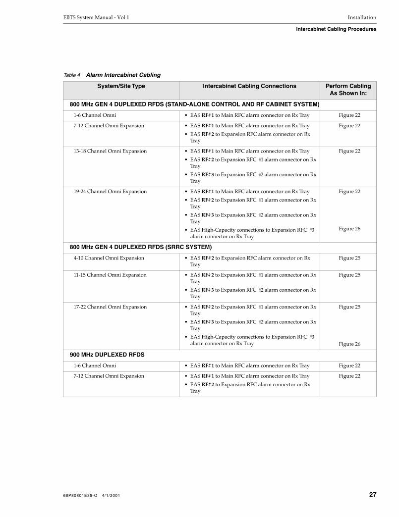
EBTS System Manual - Vol 1 Installation
Intercabinet Cabling Procedures
Table 4 Alarm Intercabinet Cabling
System/Site Type Intercabinet Cabling Connections Perform Cabling As Shown In:
800 MHz GEN 4 DUPLEXED RFDS (STAND-ALONE CONTROL AND RF CABINET SYSTEM)
1-6 Channel Omni • EAS RF#1 to Main RFC alarm connector on Rx Tray Figure 22
7-12 Channel Omni Expansion • EAS RF#1 to Main RFC alarm connector on Rx Tray
• EAS RF#2 to Expansion RFC alarm connector on Rx Tray
Figure 22
13-18 Channel Omni Expansion • EAS RF#1 to Main RFC alarm connector on Rx Tray
• EAS RF#2 to Expansion RFC #1 alarm connector on Rx Tray
• EAS RF#3 to Expansion RFC #2 alarm connector on Rx Tray
Figure 22
19-24 Channel Omni Expansion • EAS RF#1 to Main RFC alarm connector on Rx Tray
• EAS RF#2 to Expansion RFC #1 alarm connector on Rx Tray
• EAS RF#3 to Expansion RFC #2 alarm connector on Rx Tray
• EAS High-Capacity connections to Expansion RFC #3 alarm connector on Rx Tray
Figure 22
Figure 26
800 MHz GEN 4 DUPLEXED RFDS (SRRC SYSTEM)
4-10 Channel Omni Expansion • EAS RF#2 to Expansion RFC alarm connector on Rx Tray
Figure 25
11-15 Channel Omni Expansion • EAS RF#2 to Expansion RFC #1 alarm connector on Rx Tray
• EAS RF#3 to Expansion RFC #2 alarm connector on Rx Tray
Figure 25
17-22 Channel Omni Expansion • EAS RF#2 to Expansion RFC #1 alarm connector on Rx Tray
• EAS RF#3 to Expansion RFC #2 alarm connector on Rx Tray
• EAS High-Capacity connections to Expansion RFC #3 alarm connector on Rx Tray
Figure 25
Figure 26
900 MHz DUPLEXED RFDS
1-6 Channel Omni • EAS RF#1 to Main RFC alarm connector on Rx Tray Figure 22
7-12 Channel Omni Expansion • EAS RF#1 to Main RFC alarm connector on Rx Tray
• EAS RF#2 to Expansion RFC alarm connector on Rx Tray
Figure 22
68P80801E35-O 4/1/2001 27

Installation EBTS System Manual - Vol 1
Intercabinet Cabling Procedures
800 MHz CAVITY COMBINING RFDS
1-5 Channel Omni • EAS RF#1 to Main RFC ALARM connector on Power Supply Tray
Figure 23
6-10 Channel Omni Expansion • EAS RF#1 to Main RFC ALARM connector on Power Supply Tray
• EAS RF#2 to Expansion RFC ALARM connector on Power Supply Tray
Figure 23
11-15 Channel Omni Expansion • EAS RF#1 to Main RFC ALARM connector on Power Supply Tray
• EAS RF#2 to Expansion RFC #1 ALARM connector on Power Supply Tray
• EAS RF#3 to Expansion RFC #2 ALARM connector on Power Supply Tray
Figure 23
16-20 Channel Omni Expansion • EAS RF#1 to Main RFC ALARM connector on Power Supply Tray
• EAS RF#2 to Expansion RFC #1 ALARM connector on Power Supply Tray
• EAS RF#3 to Expansion RFC #2 ALARM connector on Power Supply Tray
• High-Capacity EAS connection to Expansion RFC #3 ALARM connector on Power Supply Tray
Figure 23
Figure 26
Sectored • EAS RF#1 to Main RFC #1 ALARM connector on Power Supply Tray
• EAS RF#2 to Main RFC #2 ALARM connector on Power Supply Tray
• EAS RF#3 to Main RFC #3 ALARM connector on Power Supply Tray
Figure 24
800 MHz DUPLEXED RFDS (0182020V06 and prior)
NOTE: 800 MHz Duplexed RFDS (0182020V06 and prior) is no longer available. It has been replaced by the 800 MHz GEN 4 Duplexed RFDS.
All information herein regarding 800 MHz Duplexed RFDS (0182020V06 and prior) is for reference only.
1-5 Channel Omni • EAS RF#1 to Main RFC ALARM connector Figure 20
5-8 Channel Duplex Hybrid Expansion • EAS RF#1 to Main RFC ALARM connector
• EAS RF#2 to Expansion RFC ALARM connector on Power Supply Tray
Figure 20
9-12 Channel Duplex Hybrid Expansion • EAS RF#1 to Main RFC ALARM connector
• EAS RF#2 to Expansion RFC #1 ALARM connector on Power Supply Tray
• EAS RF#3 to Expansion RF Cabinet #2 ALARM connector on Power Supply Tray
Figure 20
Sectored • EAS RF#1 to Main RFC #1 ALARM connector
• EAS RF#2 to Main RFC #2 ALARM connector
• EAS RF#3 to Main RFC #3 ALARM connector
Figure 21
Table 4 Alarm Intercabinet Cabling (Continued)
System/Site Type Intercabinet Cabling Connections Perform Cabling As Shown In:
28 68P80801E35-O 4/1/2001

EBTS System Manual - Vol 1 Installation
Intercabinet Cabling Procedures
Figure 20 Alarm Connections for 800 MHz Duplexed RFDS (0182020V06 or earlier) Omni Sites
Figure 21 Alarm Connections for 800 MHz Duplexed RFDS (0182020V06 and earlier) Sectored Sites
RF#3RF#2RF#1CONTROLSERIALPARALLELCONTROLLER B
SERIALPARALLELCONTROLLER A
RTN
-48V
USER ALARM/CONTROL SYSTEM ALARM/CONTROL
ENVIRONMENTAL ALARM SYSTEMMotorola -48V , 1.0A
ALARM POWER MON. AMP POWER
POWERIN
PO
WE
R A
MP
3
PO
WE
R A
MP
2
PO
WE
R A
MP
1
RE
SE
T
TO
WE
R A
MP
3
TO
WE
R A
MP
2
TO
WE
R A
MP
1
AM
P 3
AM
P 2
AM
P 1
ALARMOUT POWER
IN
GND
ALARM POWER MON. AMP POWER
POWERIN
PO
WE
R A
MP
3
PO
WE
R A
MP
2
PO
WE
R A
MP
1
RE
SE
T
TO
WE
R A
MP
3
TO
WE
R A
MP
2
TO
WE
R A
MP
1
AM
P 3
AM
P 2
AM
P 1
ALARMOUT POWER
IN
GND
EBTS271011901JNM
MAINRF CABINET
EXPANSIONRF CABINET #2
EXPANSIONRF CABINET #1EAS
3084225N423084225N42
3084225N42
IN OUTETHERNET 5 MHz/1PPS
ISOLATED GROUND
RX3 RX2 RX1GPS BGPS ABMR ANTTX OUT
ALARMIN OUT ETHERNET(GROUNDED)
NOTE: 1-5 channel site uses Main RFC only. 5-8 channel site uses Main RFC and expansion RFC.9-12 channel site uses Main RFC and expansion RFCs #1 and #2.
RF#3RF#2RF#1CONTROLSERIALPARALLELCONTROLLER B
SERIALPARALLELCONTROLLER A
RTN
-48V
USER ALARM/CONTROL SYSTEM ALARM/CONTROL
ENVIRONMENTAL ALARM SYSTEMMotorola -48V , 1.0A
EBTS308011901JNM
3084225N42
EAS
RF CABINET #1
RF CABINET #2
RF CABINET #3
3084225N42
3084225N42
RF#3RF#2RF#1
IN OUTETHERNET 5 MHz/1PPS
ISOLATED GROUND
RX3 RX2 RX1GPS BGPS ABMR ANTTX OUT
ALARMIN OUT ETHERNET(GROUNDED)
IN OUTETHERNET 5 MHz/1PPS
ISOLATED GROUND
RX3 RX2 RX1GPS BGPS ABMR ANTTX OUT
ALARMIN OUT ETHERNET(GROUNDED)
IN OUTETHERNET 5 MHz/1PPS
ISOLATED GROUND
RX3 RX2 RX1GPS BGPS ABMR ANTTX OUT
ALARMIN OUT ETHERNET(GROUNDED)
68P80801E35-O 4/1/2001 29

Installation EBTS System Manual - Vol 1
Intercabinet Cabling Procedures
Figure 22 Alarm Connections for 800 MHz GEN 4 Duplexed RFDS / 900 MHz Duplexed RFDS Sites (Stand-alone Control And RF Cabinet configuration)
Figure 23 Alarm Connections for Cavity Combining RFDS Omni Sites
EBTS481011901JNM
EAS
T9IN T8IN T7IN T6OUT T4IN T3IN T2IN T1OUT
MAIN RF CABINET
EXPANSION RF CABINET #2EXPANSION RF CABINET #1
T9IN T8IN T7OUT T6IN T5IN T3IN T2IN T1OUTT4OUT
T9IN T8IN T7OUT T6IN T5IN T3IN T2IN T1OUTT4OUT
T9IN T8IN T7OUT T6IN T5IN T3IN T2IN T1OUTT4OUT
T9IN T8IN T7OUT T6IN T5IN T3IN T2IN T1OUTT4OUT
RF#3RF#2RF#1CONTROLSERIALPARALLELCONTROLLER B
SERIALPARALLELCONTROLLER A
RTN
-48V
USER ALARM/CONTROL SYSTEM ALARM/CONTROL
ENVIRONMENTAL ALARM SYSTEMMotorola -48V , 1.0A
3084225N42
3084225N42
3084225N42
NOTES: 1. For systems using more than 2 Expansion RFCs, additional EAS connections are as shown in Figure 26, Alarm Connections (High Capacity Systems).
2. Rx Tray using CTF6220A version I/O Board requires extra cable between cable 3084225N42 and I/O RJ-45 connector (as shown by dashed lines). (This applies to main and/or expansion RF cabinets.) Refer to 800 MHz GEN 4 Duplexed RFDS section of manual for more information.
RF#3RF#2RF#1CONTROLSERIALPARALLELCONTROLLER B
SERIALPARALLELCONTROLLER A
RTN
-48V
USER ALARM/CONTROL SYSTEM ALARM/CONTROL
ENVIRONMENTAL ALARM SYSTEMMotorola -48V , 1.0A
EAS RF#1 RF#2 RF#3 EBTS480011901JNM
3084225N42
ALARM POWER MON. AMP POWER
POWERIN
PO
WE
R A
MP
3
PO
WE
R A
MP
2
PO
WE
R A
MP
1
RE
SE
T
TO
WE
R A
MP
3
TO
WE
R A
MP
2
TO
WE
R A
MP
1
AM
P 3
AM
P 2
AM
P 1 POWER
IN
GND
ALARM POWER MON. AMP POWER
POWERIN
PO
WE
R A
MP
3
PO
WE
R A
MP
2
PO
WE
R A
MP
1
RE
SE
T
TO
WE
R A
MP
3
TO
WE
R A
MP
2
TO
WE
R A
MP
1
AM
P 3
AM
P 2
AM
P 1 POWER
IN
GND
ALARM POWER MON. AMP POWER
POWERIN
PO
WE
R A
MP
3
PO
WE
R A
MP
2
PO
WE
R A
MP
1
RE
SE
T
TO
WE
R A
MP
3
TO
WE
R A
MP
2
TO
WE
R A
MP
1
AM
P 3
AM
P 2
AM
P 1 POWER
IN
GND
EXPANSION RF CABINET #2
EXPANSION RF CABINET #1
MAIN RF CABINET3084225N42
3084225N42
ALARMOUT
ALARMOUT
ALARMOUT
NOTE: 1-5 channel site uses Main RFC only. 6-10 channel site uses Main RFC and expansion RFC.11-15 channel site uses Main RFC and two expansion RFCs.16-20 channel site uses Main RFC and three expansion RFCs. For systems using more than 3 RFCs, additional EAS connections are as shown in Figure 26, Alarm Connections (High Capacity Systems).
30 68P80801E35-O 4/1/2001

EBTS System Manual - Vol 1 Installation
Intercabinet Cabling Procedures
Figure 24 Alarm Connections for Cavity Combining RFDS Sectored Sites
Figure 25 Alarm Connections for SRRC Expansion Sites
RF#3RF#2RF#1CONTROLSERIALPARALLELCONTROLLER B
SERIALPARALLELCONTROLLER A
RTN
-48V
USER ALARM/CONTROL SYSTEM ALARM/CONTROL
ENVIRONMENTAL ALARM SYSTEMMotorola -48V , 1.0A
EAS RF#1 RF#2 RF#3 EBTS479011901JNM
3084225N42
ALARM POWER MON. AMP POWER
POWERIN
PO
WE
R A
MP
3
PO
WE
R A
MP
2
PO
WE
R A
MP
1
RE
SE
T
TO
WE
R A
MP
3
TO
WE
R A
MP
2
TO
WE
R A
MP
1
AM
P 3
AM
P 2
AM
P 1 POWER
IN
GND
ALARM POWER MON. AMP POWER
POWERIN
PO
WE
R A
MP
3
PO
WE
R A
MP
2
PO
WE
R A
MP
1
RE
SE
T
TO
WE
R A
MP
3
TO
WE
R A
MP
2
TO
WE
R A
MP
1
AM
P 3
AM
P 2
AM
P 1 POWER
IN
GND
ALARM POWER MON. AMP POWER
POWERIN
PO
WE
R A
MP
3
PO
WE
R A
MP
2
PO
WE
R A
MP
1
RE
SE
T
TO
WE
R A
MP
3
TO
WE
R A
MP
2
TO
WE
R A
MP
1
AM
P 3
AM
P 2
AM
P 1 POWER
IN
GND
RF CABINET #3
RF CABINET #2
RF CABINET #13084225N42
3084225N42
ALARMOUT
ALARMOUT
ALARMOUT
EBTS521021501RIG
SRRC PRIMARYCABINET
EXPANSION RF CABINET #2EXPANSION RF CABINET #1
IN OUTETHERNET 5 MHz/1PPS
ISOLATED GROUND
RX3 RX2 RX1GPS BGPS ABMR ANTTX OUT
ALARMIN OUT ETHERNET(GROUNDED)
STATUS RFS3 BR3 & BR4 BR1 & BR2RFS4RFS1 & RFS2
B -48Vdc A B RETURN A
BR5 & BR6
IN OUTETHERNET 5 MHz/1PPS
ISOLATED GROUND
RX3 RX2 RX1GPS BGPS ABMR ANTTX OUT
IN OUT ETHERNET(GROUNDED)
STATUS RFS3 BR3 & BR4 BR1 & BR2RFS4RFS1 & RFS2
B -48Vdc A B RETURN A
BR5 & BR6
10B2-1123 10/100B-T10B2-210B2-3X.21
SITE REF OUT
PARALLELSERIALREDUND4321
T1/E1
GPS
-48V RTN
BAT
RF#3RF#2RF#1CONTROLSERIALPARALLELCONTROLLER B
SERIALPARALLELCONTROLLER A
RTN
-48V
USER ALARM/CONTROL SYSTEM ALARM/CONTROL
ENVIRONMENTAL ALARM SYSTEMMotorola -48V , 1.0A
10B2-1123 10/100B-T10B2-210B2-3X.21
SITE REF OUT
PARALLELSERIALREDUND4321
T1/E1
GPS
-48V RTN
BAT
EAS(NOTE 3) (NOTE 3)
ALARMALARM
3084225N42
3084225N42
NOTES: 1. For systems using more than 2 Expansion RFCs, additional EAS connections are as shown in Figure 26, Alarm Connections (High Capacity Systems).
2. Only alarm cabling to expansion cabinets shown. For alarm cabling within SRRC primary cabinet, refer to Single Rack, Redundant Controller GEN 4 EBTS section in this manual.
3. Rx Tray using CTF6220A version I/O Board requires extra cable between cable 3084225N42 and I/O RJ-45 connector (as shown by dashed lines). (This applies to primary and/or expansion RF cabinets.) Refer to Single Rack, Redundant Controller GEN 4 EBTS section of manual for more information.
68P80801E35-O 4/1/2001 31

Installation EBTS System Manual - Vol 1
Intercabinet Cabling Procedures
Figure 26 Alarm Connections (High Capacity Systems)
RF#3RF#2RF#1CONTROLSERIALPARALLELCONTROLLER B
SERIALPARALLELCONTROLLER A
RTN
-48V
USER ALARM/CONTROL SYSTEM ALARM/CONTROL
ENVIRONMENTAL ALARM SYSTEMMotorola -48V , 1.0A
EBTS370040201JNM
3083892X03
PUNCH BLOCK 2
EAS
3084966K06
MODULARADAPTER
(2882174W03)
TO RF CABINET #4(EXPANSION
RF CABINET #3)
TO MAINRF CABINET
TO EXPANSIONRF CABINET #2
TO EXPANSIONRF CABINET #1
(NOT USED) TO RFCABINET #6
TO RFCABINET #5
TO RFCABINET #8
TO RFCABINET #7
32 68P80801E35-O 4/1/2001

EBTS System Manual - Vol 1 Installation
Intercabinet Cabling Procedures
Primary Control Channel Redundancy Intercabinet Cabling
NOTE
The following procedure applies only to Cavity Combining systems using multiple RF Cabinets.
On a cavity combining RFDS, additional signalling connections must be made for Primary Control Channel (PCCH) redundancy. There is a PCCH redundancy control cable for each RF Cabinet used in the system.
The red wire is routed to RF Cabinet 1, the blue wire is routed to RF Cabinet 2, and the green wire is routed to RF Cabinet 3. RF Cabinets 2 and 3 are only used in sectored sites. All of the PCCH redundancy control wires (red, blue, and green) branch from the Control Cabinet modular cable connection on the rear of the EAS.
1. On the EAS, locate the modular cable that is plugged into the Control Cabinet connector.
The end of this cable contains three separate branched wires that are colored red, blue, and green.
2. Locate the Mate-N-Lok connector at the end of a colored wire.
This is a PCCH redundancy control connection for a specific RF Cabinet. Refer to the paragraph at the beginning of this procedure for definitions of wire colors.
NOTE
Make sure that each wire is routed to the appropriate RF Cabinet. Red is for RF Cabinet 1, blue is for RF Cabinet 2, and green is for RF Cabinet 3.
3. Route the colored cable to the appropriate RF Cabinet.
4. In the RF Cabinet, locate the loose cable containing another Mate-N-Lok connector.
This cable is connected to the antenna relay on the rear of the RF Cabinet and to the Auxiliary connector on the BR backplane.
5. Connect the two Mate-N-Lok connectors from the Control Cabinet and RF Cabinet together.
6. Repeat this procedure for additional RF Cabinets, if necessary.
7. Proceed to Power Supply Rack-to-EBTS Power (-48 VDC) Connections.
68P80801E35-O 4/1/2001 33

Installation EBTS System Manual - Vol 1
Intercabinet Cabling Procedures
Power Supply Rack-to-EBTS Power (-48 VDC) Connections
WARNING!MAKE SURE ALL POWER TO THE POWER SUPPLY
RACK IS OFF TO PREVENT INJURY TO PERSONNEL.
All -48 VDC (hot) power supply connections are made between the Power Supply rack and the equipment cabinet.
The Power Supply breaker panel should be divided into two sections: A and B. Both sides are connected to the same power source and have the same potential. Figure 28 shows a typical breaker panel layout.
The Power Supply circuit breakers are typically located on the front of the Power Supply rack. When viewed from the front of the Power Supply rack, the A-side circuit breakers are on the left. The B-side breakers are on the right.
The equipment cabinet requires two power feeds to provide the operating power to the A and B sides of the cabinet. Two -48 VDC (hot) wires from individual breakers on the power supply are connected to the A and B sides of the -48 VDC EBTS breaker panel. Two DC return wires from the power supply are connected to the A and B sides of each return EBTS breaker panel. This provides two separate power feeds to the equipment cabinet. Figure 28 shows a rear view of the equipment cabinet Power Distribution Panel.
The equipment cabinet distributes the -48 VDC (hot) through individual power circuits for each module in the cabinet. These circuits are wired from the circuit breaker panel in the cabinet.
Power wiring for circuit breakers in the equipment cabinet is accessed from the rear of the cabinet on the breaker panel. The breaker panel layout is similar to that of the Power Supply rack. The A-side is on the left and the B-side is on the right, when viewed from the front.
Figure 27 Typical Equipment Cabinet Power Distribution Panel (Rear View)
CN
TR
L-A
RF
1-A
RF
2-A
RF
3-A
CN
TR
L-B
RF
1-B
RF
2-B
RF
3-B
50A 50A 50A 50A 50A 50A 50A 50A
"A" SIDE "B" SIDE
EBTS049022097JNM
34 68P80801E35-O 4/1/2001

EBTS System Manual - Vol 1 Installation
Intercabinet Cabling Procedures
Connections to the Power Supply rack are made from the front. Other EBTS connections are made from the rear of the cabinet.
Determining Power Connection Wire Gauge
Table 5 lists the required wire gauges for various installations. The “loop length” refers to the combined length of the -48 VDC (hot) lead and the DC return lead. For example, a cabinet which needs 16 feet of wire to reach the Power Supply rack has a total loop length of 32 feet.
For a standard installation, the equipment cabinet is located adjacent to the Power Supply rack with a cable loop length less than 35’.
NOTE
Wire used shall not be smaller than #6 AWG. Cable loop voltage drop shall not exceed 500 mV for cabling of the -48 VDC (hot) and DC return leads.
The screws that connect the power cables to the Power Supply rack are not provided and must be locally procured. Power Supply rack breaker panel screw size is 3/8-16 x 3/4.
Table 5 Power Connection Wire Gauge
Loop Length Wire Gauge
25 feet or less #6 AWG
25 to 40 feet #4 AWG
40 to 60 feet #2 AWG
60 to 130 feet 1/0 AWG
STATUS RFS3 BR3 & BR4 BR1 & BR2RFS4RFS1 & RFS2
B -48Vdc A B RETURN A
EBTS397112697AJF
BR5 & BR6
Figure 28 Typical Equipment Cabinet Power Distribution Panel (Rear View)
68P80801E35-O 4/1/2001 35

Installation EBTS System Manual - Vol 1
Intercabinet Cabling Procedures
NOTE
Red is the color recommended for wires considered “hot.” However, if the wire is not color coded, mark these leads with a red tracer, such as red electrical tape, on each end.
Equipment Cabinet -48 VDC Power Connections
Each equipment cabinet requires two wires for -48 VDC power (hot). Perform -48 VDC (hot) power source-to-equipment cabinet wiring as described below.
WARNING!MAKE SURE ALL POWER TO THE POWER SUPPLY
RACK IS OFF TO PREVENT INJURY TO PERSONNEL.
1. For each equipment cabinet, route two runs of appropriate-gauge bulk wiring between -48 VDC (hot) A and B side connections on equipment cabinet and Power Supply rack. Make certain wire runs are properly routed through cabinets and cable tray assembly, allowing adequate slack.
2. Depending on wire gauge used, terminate the wire ends at the Power Supply rack using appropriate double-hole crimp lugs.
3. Connect the first power wire lug to breaker 2A (RF1-A) of the Power Supply rack. (See Figure 28.)
4. On the equipment cabinet power distribution panel, strip and insert free end of wire coming from power supply RF1-A into -48 VDC terminal block A on power distribution panel. (See Figure 28.) Securely tighten connection.
5. Connect the second power wire lug to breaker 2B (RF1-B) of the Power Supply rack. (See Figure 28.)
6. On equipment cabinet power distribution panel, strip and insert free end of wire coming from power supply RF1-B into -48 VDC terminal block B on power distribution panel. (See Figure 28.) Securely tighten connection.
7. If additional RF cabinets (RFCs) are used, repeat steps 1 through 6 for RFC #2 and RFC #3) using power supply breakers RF2-(A, B) and RF3-(A, B), as applicable.
Equipment Cabinet -48 VDC Return Connections
Each equipment cabinet requires two -48 VDC return wires. Perform -48 VDC return power source-to-equipment cabinet wiring as described below.
36 68P80801E35-O 4/1/2001

EBTS System Manual - Vol 1 Installation
Intercabinet Cabling Procedures
WARNING!MAKE SURE ALL POWER TO THE POWER SUPPLY
RACK IS OFF TO PREVENT POSSIBLE INJURY TO
PERSONNEL.
1. On the Power Supply rack, access the ground bus. Refer to the Power Supply manual supplied with the Power Supply cabinet for the location and access information for the ground bus.
2. Using appropriate gauge wire, route two runs of bulk wiring between A and B side RETURN connections on equipment cabinet and Power Supply rack RETURN connections. Make certain wire runs are properly routed through cabinets and cable tray assembly, allowing adequate slack.
3. Depending on wire gauge used, terminate the two wire ends at the Power Supply rack using appropriate double-hole crimp lugs.
4. Connect the first DC return wire lug to the DC return bus bar on the Power Supply rack. (See Figure 29.)
5. On equipment cabinet power distribution panel, strip and insert free end of wire coming from power supply A-side return into RETURN terminal block A. (See Figure 28.) Securely tighten connection.
6. Connect the second DC return wire lug to the DC return bus bar on the Power Supply rack. (See Figure 29.)
7. On equipment cabinet power distribution panel, strip and insert free end of wire coming from power supply B-side return into RETURN terminal block B. (See Figure 28.) Securely tighten connection.
8. Proceed to Cabinet-to-Site Cabling Procedures.
Site Controller Cabinet Power Connections
For SCRF systems, refer to the Gen 3 SC Supplement to this manual for information on connecting the Gen 3 SC control cabinet to the power supply rack.
TO RF CABINET
#1
TO RF CABINET
#2
TO RF CABINET
#3
TO CONTROLCABINET
EBTS051042794JNM
1 2 3 4 5 6 7 8 9 10 11 12 13 1415 16 17 18 19
20
21
22 24
2523
27 28
LOAD RETURNS
26
TO BATTERYPOSITIVE (+)TERMINAL
Figure 29 Typical Power Supply Rack DC Return Bus (Front View)
68P80801E35-O 4/1/2001 37

Installation EBTS System Manual - Vol 1
Cabinet-to-Site Cabling Procedures
Cabinet-to-Site Cabling Procedures
Perform the following cabinet-to-site cabling procedures as applicable to the system being installed.
NOTE
Unless otherwise noted, all cabling procedures herein apply to and shall be performed for all EBTS configurations. Where differences or exceptions exist, they are noted.
AC Mains Connection (SRSC Systems Only)
The AC/DC Power System within the SRSC cabinet is equipped with a 250V, 30A Twist-Lock NEMA standard plug. AC mains connection is accomplished by merely connecting the plug to an appropriate 240 VAC receptacle.
WARNING!HIGH LEAKAGE CURRENT PRESENT! EARTH
CONNECTION ESSENTIAL BEFORE CONNECTING
SUPPLY.
An equipment grounding conductor that is equal to orgreater in size than the ungrounded branch circuitsupply conductor is to be installed as part of thebranch circuit that supplies the equipment. Barecovered or insulated grounding conductors areacceptable. Individually covered or insulatedequipment grounding conductors shall have acontinuous outer finish that is either green, or greenwith one or more yellow stripes. The equipmentgrounding conductor is to be connected to ground atthe service equipment.
The attachment plug receptacles in the vicinity of theequipment are all to be of a grounding type, and theequipment grounding conductors serving thesereceptacles are to be connected to earth ground at theservice equipment.
38 68P80801E35-O 4/1/2001

EBTS System Manual - Vol 1 Installation
Cabinet-to-Site Cabling Procedures
NOTE
AC mains specifications delineated in Pre-Installation section of this manual shall be observed for AC mains supply to SRSC cabinet.
The SRSC cabinet can facilitate connection to the AC mains via either a power cord (provided) or permanent means (i.e., conduit). If the site installation requires the connection of AC mains power via permanent means, use the following procedure.
1. Remove the AC power cord that is provided with the AC/DC Power System by loosening the three terminal screws and removing the two power cord retaining clamps on the back of the unit as shown in Figure 30.
2. Attach a Listed 4"x2-1/8" extension ring to the back of the AC/DC Power System with the screws provided as illustrated in Figure 31.
EBTS670101498JNM
GL1 L2
AC INPUT
G T +12V
TEMP SENSOR
CNTRL 2 CNTRL 1IMU
RFDS1RFDS2
BR3BR4
BR1BR2
BATTGROUND
BATT-48V
TEMP SENSOR
CBA ACF HVA LVA MIN MAJ
CAUTION:220VAC
AC POWER CORD
POWER CORDRETAINING
CLAMPS
AC MAINTERMINAL SCREWS (3)
Figure 30 AC/DC Power System - Rear Panel
68P80801E35-O 4/1/2001 39

Installation EBTS System Manual - Vol 1
Cabinet-to-Site Cabling Procedures
3. Attach the Line 1, Line 2, and Earth Ground wires to the proper terminals as marked on the back of the AC/DC Power System.
4. Attach a Listed 4" x 2-1/8" blank cover over the extension ring.
CAUTION:220VAC
EBTS671101498JNM
GL1 L2
AC INPUT
G T +12V
TEMP SENSOR
CNTRL 2 CNTRL 1
IMURFDS1RFDS2
BR3BR4
BR1BR2
BATTGROUND
BATT-48V
TEMP SENSOR
CBA ACF HVA LVA MIN MAJ
SCREWS
4” x 2-1/8”EXTENSION RING
Figure 31 AC/DC Power System - Extension Ring Installation
40 68P80801E35-O 4/1/2001

EBTS System Manual - Vol 1 Installation
Cabinet-to-Site Cabling Procedures
Battery Backup Connections (SRSC Systems Only)
The AC/DC Power System within the SRSC cabinet is equipped to directly accommodate a -48V lead-acid battery backup system. Connect AC/DC Power System to battery rack observing the guidelines below.
CAUTIONThe battery backup system cables should be sized appropriately for the battery charging capacity of the AC/DC Power System, the load requirements of the SRSC cabinet, and the applicable electrical codes. Refer to the Motorola iDEN -48V DC Power System Installation, Operation and Maintenance Manualp/n 0-SY001026-1 for power system charging capacity. The SRSC cabinet maximum load requirement is approximately 55 Amps @ 42VDC.
CAUTIONThe SRSC AC/DC Power System is intended for use with valve-regulated, lead-acid batteries ONLY. Make sure that the AC/DC Power System float voltage is set to 54VDC.
CAUTIONUse a minimum battery backup system capacity of 66 ampere-hours with the SRSC AC/DC Power System.
CAUTIONIf batteries are to be mounted within the rack, a suitable battery support shelf must be used which is capable of supporting the total battery weight and containing any electrolyte leakage.
68P80801E35-O 4/1/2001 41

Installation EBTS System Manual - Vol 1
Cabinet-to-Site Cabling Procedures
CAUTIONInstallation, maintenance and servicing of batteries should only be performed by trained personnel. Consult your battery supplier for further technical information and assistance.
CAUTIONThe AC/DC Power System is to be connected to a battery system that is in accordance with any and all applicable electrical codes for the end-use country (for example, the National Electrical Code ANSI/NFPA 70 in USA).
WARNING!BATTERY TERMINALS CAN SUPPLY HIGH CURRENT.
AVOID CONTACT WITH CONDUCTIVE OBJECTS. TURN
OFF POWER TO THE POWER SUPPLY SYSTEM AND
DISCONNECT BATTERY BACKUP SYSTEM BEFORE
SERVICING TO AVOID INJURY TO PERSONNEL.
WARNING!MAKE SURE ALL BREAKERS ON AC/DC POWER
SUPPLY ARE SET TO OFF BEFORE PERFORMING
CONNECTIONS. FAILURE TO OBSERVE THIS WARNING
MAY RESULT IN INJURY TO PERSONNEL.
CONNECTION SHALL INCLUDE A FUSE INSTALLED ON
HOT SIDE OF WIRING.
42 68P80801E35-O 4/1/2001

EBTS System Manual - Vol 1 Installation
Cabinet-to-Site Cabling Procedures
Connecting Details
A -48V (hot) and ground connection is made between the rear panel BATT -48V and BATT GROUND terminal lugs on the AC/DC Power System and the battery rack (terminal lugs on power system are copper plated studs which accept 10-32 nuts). Connecting details are shown in Figure 32.
As shown, a fuse shall be used on the “hot” side of the circuit.
WARNING!TYPICAL BATTERY INSTALLATION UTILIZES A SPECIAL
BATTERY RACK. IF BATTERIES ARE INSTALLED IN
SRSC CABINET, THE CONSIDERATIONS SPECIFIED IN
MOTOROLA STANDARDS AND GUIDELINES FOR
COMMUNICATIONS SITES (R56) 68P81089E50 MUST BE
OBSERVED.
FAILURE TO PROPERLY INSTALL BATTERY SYSTEM
CAN RESULT IN AN EXPLOSION HAZARD TO
PERSONNEL AND SITE, AND POSSIBLE EQUIPMENT
DAMAGE DUE TO ELECTROLYTE LEAKAGE AND/OR
OUTGASSING.
EBTS672101298JNM
BATTGROUND
BATT-48V
RED
BLK
(NOTE 2)
(NOTE 3)BATTERYSYSTEM
BATTERY CONNECTIONTERMINAL STUDS
(NOTE 1)
FUSE ASSY
NOTES: 1. Battery connection terminal studs are for use with #12-#1 AWG copper wire only. 2. Refer to battery system manufacturer’s instructions for connections to battery
system and required wire gauge. 3. -48V (hot) lead between battery system and AC/DC Power System shall be fused using inline
fuseholder (Buss P/N G30060-1CR, or equivalent) and 60A time delay cartridge fuse (BussP/N SC-60, or equivalent).
68P80801E35-O 4/1/2001 43

Installation EBTS System Manual - Vol 1
Cabinet-to-Site Cabling Procedures
Figure 32 SRSC Battery Backup Connections
Equipment Cabinet Ground Connections Cabinet grounding wires may have been installed prior to cabinet installation. If so, follow the instructions below. If grounding wires have not yet been installed, refer to the Grounding Requirements in the Pre-Installation section of this manual.
Perform the procedure below that applies to the particular system being installed.
NOTE
Single-point ground method (where each cabinet or rack is grounded to master ground using its own ground wire) shall be used. Equipment cabinet shall use green-insulation #2 AWG (or larger) for ground wire.
During installation of cabinet ground wires, be sure tocheck any factory-installedinternal ground connections for tightness.
44 68P80801E35-O 4/1/2001

EBTS System Manual - Vol 1 Installation
Cabinet-to-Site Cabling Procedures
RF Cabinet Grounding For 800 MHz Duplexed RFDS (0182020V06 Duplexed RFDS)
NOTE
800 MHz Duplexed RFDS (0182020V06 and prior) is no longer available. It has been replaced by the 800 MHz GEN 4 Duplexed RFDS.
All information herein regarding 800 MHz Duplexed RFDS (0182020V06 and prior) is for reference only.
On RF Cabinets using a 0182020V06 Duplexed RFDS, the ground cable connects to the ground studs on each Duplexer chassis. Figure 33 shows the ground connections for the duplexed RFDS.
Figure 33 Ground Connection for 800 MHz (0182020V06) Duplexed RFDS (Rear View)
EBTS342021797JNM
"A" "B"
E X PA N S I O N
"A" "B"
E X PA N S I O N
STATUS BR5 BR3 & BR4 BR1 & BR2RFS1RFS2
B -48Vdc A B RETURN A
IN OUTETHERNET 5 MHz/1PPS
ISOLATED GROUND
RX3 RX2 RX1GPS BGPS ABMR ANTTX OUT
ALARMIN OUT ETHERNET(GROUNDED)
GROUND STUDS (3)
68P80801E35-O 4/1/2001 45

Installation EBTS System Manual - Vol 1
Cabinet-to-Site Cabling Procedures
Cabinet Grounding (SCRF, SRRC, and SRSC Using800 MHz GEN 4 Duplexed RFDS)
On any cabinet using an 800 MHz GEN 4 Duplexed RFDS, a ground cable connects to the ground stud on each Duplexer chassis. On the Rx Tray, a ground cable is connected to the stud on the bracket assembly. Figure 34 shows the ground connections for the 800 MHz GEN 4 Duplexed RFDS.
EBTS465110597JNM
T9IN T8IN T7IN T6OUT T4IN T3IN T2IN T1OUT
DUPLEXERGROUND
STUDS (3)
RX TRAYGROUND STUD
Figure 34 Ground Connection for 800 MHz GEN 4 Duplexed RFDS(Rear View)
46 68P80801E35-O 4/1/2001

EBTS System Manual - Vol 1 Installation
Cabinet-to-Site Cabling Procedures
RF Cabinet Grounding (Cavity Combining RFDS)
On RF Cabinets using a cavity combining RFDS, the ground wire connects to the output port antenna stud on the RFDS ground plate. Figure 35 shows the ground connection for the cavity combining RF Cabinet.
Figure 35 Ground Connection for Cavity Combining RFDS (Rear View)
ALARM POWER MON. AMP POWER
POWER IN BP
OW
ER
AM
P 3
PO
WE
R A
MP
2
PO
WE
R A
MP
1
RE
SE
T
TO
WE
R A
MP
3
TO
WE
R A
MP
2
TO
WE
R A
MP
1
AM
P 3
AM
P 2
AM
P 1
ALARM OUT POWER
IN A
2 1
4 3
5
GND
POWER MON.
F R F R F R
5 4 3 2 1OUT EXP
IN
OUT EXP
IN
OUT EXP
IN
EBTS033050694JNM
CABINET GROUNDING
STUD
68P80801E35-O 4/1/2001 47

Installation EBTS System Manual - Vol 1
Cabinet-to-Site Cabling Procedures
RF Cabinet Grounding (900 MHz Duplexed RFDS)
On 900 MHz RF Cabinets, a ground cable connects to the ground stud on each Duplexer chassis. On the Rx Tray, a ground cable is connected to the stud on the bracket assembly. Figure 36 shows the ground connections for the 900 MHz RFDS.
EBTS464110597JNM
T9IN T8IN T7IN T6OUT T4IN T3IN T2IN T1OUT
DUPLEXERGROUND
STUDS (3)
RX TRAYGROUND STUD
Figure 36 Ground Connection for 900 MHz RFDS (Rear View)
48 68P80801E35-O 4/1/2001

EBTS System Manual - Vol 1 Installation
Cabinet-to-Site Cabling Procedures
Equipment Cabinet Grounding to Site Master Ground Bar
On the Equipment Cabinet, ground connects to either of the two ground studs on the Junction Panel.
Perform the following steps to ground the chassis of the cabinet to the master ground bar.
NOTE
A hex nut is secured to the Junction Panel of each cabinet during manufacturing. This nut is used to make ground connections on the Junction Panel. It may also be removed from the Junction Panel and used for the ground connections on the RF Distribution System.
1. Remove the nut and star washer from the ground stud and set it aside.
2. Strip the end of the wire to be connected to the cabinet ground.
3. Using appropriate tool, attach a crimp lug onto the cabinet ground wire. Make certain lug is securely fastened to wire.
4. Route the cabinet ground wire through the top of the cabinet.
5. Place the lug over the ground stud and secure it with the nut removed in step 1.
6. Make sure that the other end of the cabinet ground wire is routed to the master ground bar.
7. Strip the end of the wire for connection to the master ground bar.
8. Using appropriate tool, attach a dual-hole crimp lug onto the wire. Make certain lug is securely fastened to wire.
NOTE
If necessary, refer to Appendix B - Parts and Suppliers for recommended crimp lugs.
9. Secure the ground wire lug to the master ground bar using the appropriate tools and hardware.
68P80801E35-O 4/1/2001 49

Installation EBTS System Manual - Vol 1
Cabinet-to-Site Cabling Procedures
Base Radio Antenna Connections This sub-section assumes the Base Radio antennas have been previously installed. The antenna leads should be dropped above the EBTS cabinets as per the site plan.
Make sure the antenna cables are properly marked. Observe the direction of corresponding antennas while correlating the azimuth to the tagged antenna cable. Be sure to document this information for future use.
Perform the procedure below that applies to the particular system being installed.
NOTE
The RFDS uses female N-type or 7/16” DIN connectors on the antenna ports. The N-type connectors have gold plated center conductors and silver plated outer shells. The 7/16” DIN connectors have silver plated inner conductors and silver plated outer conductors. Motorola recommends using material matching connectors on all antenna connections.
800 MHz GEN 4 Duplexed RFDS Antenna Connections (SCRF, SRRC, and SRSC Using 800 MHz GEN 4 Duplexed RFDS)
The following procedure applies to all configurations using the 800 MHz GEN 4 RFDS. Perform cabling as follows:
1. Identify all antenna cables designated for the RF Cabinets.
All antenna cables must enter through the top of the cabinets. Extension cables for the antenna feedlines must be procured locally. Superflex™ 1/2” cable is the recommended extension cable.
2. Tag each of the antenna cables to identify the Sector number (where applicable) and the RF Cabinet number (where applicable).
3. Where applicable, sectors and RF Cabinets are marked 1 through 3. Refer to Antenna Installation in the Pre-Installation section for the recommended color coding to tag the antennas.
4. Connect each of the tagged antenna cables to the N-type connectors on the RFDS as follows:
• Duplexed RFDS withoutTower Top Amplifier compatibility – Connect antenna cables to RFDS duplexer antenna ports as shown in Figure 37.
• Duplexed RFDS with Tower Top Amplifier (TTAs) compatibility – Connect antenna cables to DC injector on each duplexer antenna port as shown in Figure 38.
50 68P80801E35-O 4/1/2001

EBTS System Manual - Vol 1 Installation
Cabinet-to-Site Cabling Procedures
5. On system using Expansion RF Cabinet #3 (19-24 channel expansion in Stand-alone Control And RF Cabinet system or 17-22 channel expansion in SRRC system), connect transmit-only (fourth) antenna to Expansion RF Cabinet #3. (Antenna connection is similar to that shown in Figure 37.)
6. To continue, perform one of the following:
• Multi-sectored site – Repeat steps 1 through 3 for RF Cabinet #2 and RF Cabinet #3, as necessary.
• Omni sites – Proceed to GPS Antenna Connections.
EBTS457122297AJF
ANTENNA 1ANTENNA 2ANTENNA 3ANTENNA 4(TX ONLY)
EXPANSION RF CABINET #3(19-21 BR EXPANSION ONLY)
MAIN RF CABINET
Figure 37 800 MHz GEN 4 Duplexed RFDS Antenna Connections, Non-TTA (Rear View)
SURGE
PROTECTED
SURGE
PROTECTED
SURGE
PROTECTED
EBTS535032798JNM
ANTENNA 3 ANTENNA 2 ANTENNA 1
Figure 38 800 MHz GEN 4 Duplexed RFDS Antenna Connections, TTA (Rear View)
68P80801E35-O 4/1/2001 51

Installation EBTS System Manual - Vol 1
Cabinet-to-Site Cabling Procedures
900 MHz Duplexed RFDS Antenna Connections
1. Identify all antenna cables designated for the RF Cabinets.
All antenna cabling must enter through the top of the cabinets. Extension cables for the antenna feedlines must be procured locally. Superflex™ 1/2” cable is the recommended extension cable.
2. Tag each of the antenna cables to identify the Sector number (where applicable) and the RF Cabinet number.
3. Where applicable, sectors and RF Cabinets are marked 1 through 3. Refer to Antenna Installation in the Pre-Installation section for the recommended color coding to tag the antennas.
4. Connect each of the tagged antenna cables to the N-type connectors on the RFDS duplexer antenna ports or Tx filter (as applicable) as shown in Figure 39.
5. To continue, perform one of the following:
• Multi-sectored site – Repeat steps 1 through 3 for RF Cabinet #2 and RF Cabinet #3, as necessary.
• Omni site – Proceed to GPS Antenna Connections.
EBTS463012098JNM
T9IN T8IN T7IN T6OUT T4IN T3IN T2IN T1OUT
MAIN RF CABINET EXPANSION RF CABINET
T3IN T2IN T1OUT
T9IN T8IN T7OUT T6IN T5IN T3IN T2IN T1OUTT4OUT
ANTENNA 1(TX/RX)ANTENNA 2
(TX/RX)ANTENNA 3
(TX/RX)
ANTENNA 5(TX)
ANTENNA 4(TX)
Figure 39 900 MHz Duplexed RFDS Antenna Connections (Rear View)
52 68P80801E35-O 4/1/2001

EBTS System Manual - Vol 1 Installation
Cabinet-to-Site Cabling Procedures
1-5 Channel Cavity Combined RFDS Antenna Connections
Refer to Figure 40 for the proper connecting points to the RFDS.
1. Identify all antenna cables designated for the RF Cabinets. Three branch diversity sites will have three receive antennas and one transmit antenna while two branch diversity sites will have two receive antennas and one transmit antenna per RF cabinet.
All antenna cabling must enter through the top of the cabinets. Extension cables for the antenna feedlines must be procured locally. Superflex™ 1/2” cable is the recommended extension cable.
2. Tag each of the antenna cables to identify the Sector number and the RF Cabinet number.
Sectors and RF Cabinets are marked 1 through 3. Refer to Antenna Installation in the Pre-Installation section of this manual for the recommended color coding to tag the antennas.
3. Connect each of the tagged receive antenna cables to the N-type connectors on the ground plate inside the RF Cabinet.
4. Connect the tagged transmit antenna cables to the DIN-type connectors on the cavity combiner inside the RF Cabinet.
5. To continue, perform one of the following:
• Multi-sectored site – Repeat steps 1 through 4 for RF Cabinet #2 and RF Cabinet #3, as necessary.
• Omni site – Proceed to GPS Antenna Connections.
6-10 Channel Cavity Combined Antenna Connections
Refer to Figure 41 for 6-10 channel omni site cabling.
1. Identify all antenna cables designated for the RF Cabinets.
All antenna cabling must enter through the top of the cabinets. Extension cables for the antenna feedlines must be procured locally. Superflex™ 1/2” cable is the recommended extension cable.
2. Tag each of the antenna cables to identify TX and RX drops.
Refer to Antenna Installation in the Pre-Installation section for the recommended color coding to tag the antennas.
3. Remove the RF Power Coupler from the Main RF Cabinet and install it to the Phasing Harness on the Expansion RF Cabinet. Refer to Figure 41 for placement.
68P80801E35-O 4/1/2001 53

Installation EBTS System Manual - Vol 1
Cabinet-to-Site Cabling Procedures
Figure 40 Cavity Combining RFDS Connections (Rear View)
ALARM POWER MON. AMP POWER
POWER
INB
PO
WE
R A
MP
3
PO
WE
R A
MP
2
PO
WE
R A
MP
1
RE
SE
T
TO
WE
R A
MP
3
TO
WE
R A
MP
2
TO
WE
R A
MP
1
AM
P 3
AM
P 2
AM
P 1
ALARM
OUTPOWER
INA
2 1
4 3
5
GND
POWER MON.
F R F R F R
5 4 3 2 1OUT EXP
IN
OUT EXP
IN
OUT EXP
IN
EBTS110021997JNM
RX BRANCH 1
RX BRANCH 2
RX BRANCH 3
NOTE: RX Branch 3 is only used in three branch diversity connections.
RX INPUT PORT
6-WAYDIVIDER
POWERCONNECTOR
IN OUT IN OUTETHERNET 5 MHz/1PPS
ISOLATED GROUND
RX3 RX2 RX1GPS BGPS AALARM TX OUT
JUNCTION PANEL
RF POWERCOUPLER
90˚ RF ELBOW(ELBOW REMOVEDWHEN PHASINGHARNESS IS USED)
TX ANTENNA
TORX
ANT 3
TORX
ANT 2
TORX
ANT 1
54 68P80801E35-O 4/1/2001

EBTS System Manual - Vol 1 Installation
Cabinet-to-Site Cabling Procedures
NOTE
The RF Power Coupler (shipped with the Main RF Cabinet) needs to be disconnected and installed on the Phasing Harness (shipped with the Expansion RF Cabinet) of the Expansion RF Cabinet.
4. Connect the RF Power Coupler forward and reverse monitor ports to the Power Monitor of the Main RF Cabinet.
5. Connect the Phasing Harness to the Cavity Combiner output, 7/16” DIN connector, of the Main RF Cabinet.
6. Connect each of the tagged receive antenna cables to the N-type connectors on the junction panel of the Main RF Cabinet.
7. Connect the receiver antenna expansion cables from the RX Expansion junction panel inside the Main RF Cabinet to the N-type connectors on the junction panel inside the Expansion RF Cabinet.
RX Expansion cables are shipped with the Expansion RF Cabinet.
NOTE
Refer to Cabling Diagrams sub-section of Cavity Combining RF Distribution System section of this manual for connecting points and cable part numbers.
8. Connect the transmit antenna drop to the output of the Power Coupler attached to the Phasing Harness.
9. Proceed to GPS Antenna Connections.
11-20 Channel Cavity Combined Antenna Connections
Refer to Figure 41 for 11-20 channel omni site cabling.
1. Perform cabling and setup as described in 6-10 Channel Cavity Combined Antenna Connections procedure above.
2. Install RF Power Coupler as follows:
• 11-15 Channel Expansion – Leave RF Power Coupler installed on RF Expansion Cabinet #2.
• 16-20 Channel Expansion – Remove the RF Power Coupler supplied with Expansion RF Cabinet #2. Install the RF Power Coupler to the Phasing Harness, as shown in Figure 41.
68P80801E35-O 4/1/2001 55

Installation EBTS System Manual - Vol 1
Cabinet-to-Site Cabling Procedures
3. Connect the RF Power Coupler forward and reverse monitor ports to the Power Monitor of Expansion RF Cabinet #2.
4. (16-20 Channel Expansion only) Connect the Phasing Harness to the Cavity Combiner output, 7/16” DIN connector, of Expansion RF Cabinet #2.
5. Connect the receiver antenna expansion cables from the RX Expansion junction panel inside the Main RF Cabinet to the N-type connectors on the junction panel inside the Expansion RF Cabinets.
RX Expansion cables are shipped with the Expansion RF Cabinets.
NOTE
Refer to Cabling Diagrams sub-section of Cavity Combining RF Distribution System section of this manual for connecting points and cable part numbers.
6. Connect the transmit antenna drop to the output of the Power Coupler attached to the Phasing Harness.
7. Proceed to GPS Antenna Connections.
56 68P80801E35-O 4/1/2001

EBTS System Manual - Vol 1 Installation
Cabinet-to-Site Cabling Procedures
Figure 41 6-10 Channel and 11-20 Channel Cavity RFDS Connections
EBTS368041797LLN
MAIN RF CABINET EXPANSION RF CABINET #1(CHANNELS 6-10)
2 1
5 4 3 2 1OUT EXP
IN
OUT EXP
IN
OUT EXP
IN
2 5
2 3
IN OUT5MHz/1 PPS
INETHERNET
OUT
ALARM POWER MON. AMP POWER
POWERIN
PO
WE
R A
MP
3
PO
WE
R A
MP
2
PO
WE
R A
MP
1
RE
SE
T
TOW
ER
AM
P 3
TOW
ER
AM
P 2
TOW
ER
AM
P 1
AM
P 3
AM
P 2
AM
P 1
ALARMOUT POWER
IN
GND
5
4 3
2 1
TRAY 3EXP 3
TRAY 3EXP 2
TRAY 3EXP 1
TRAY 2EXP 3
TRAY 2EXP 2
TRAY 2EXP 1
TRAY 1EXP 3
TRAY 1EXP 2
TRAY 1EXP 1
IN OUTETHERNET 5 MHz/1PPS
ISOLATED GROUND
RX3 RX2 RX1GPS BGPS ABMR ANTTX OUT
ALARMIN OUT ETHERNET(GROUNDED)
TO TX ANTENNA(CHANNELS 1-10)
RF POWERCOUPLER
RX EXPANSIONJUNCTION PANEL
EXPANSION RF CABINET #2(CHANNELS 11-15)
EXPANSION RF CABINET #3(CHANNELS 16-20)
2 1
5 4 3 2 1OUT EXP
IN
OUT EXP
IN
OUT EXP
IN
2 5
2 3
IN OUT5MHz/1 PPS
INETHERNET
OUT
ALARM POWER MON. AMP POWER
POWERIN
PO
WE
R A
MP
3
PO
WE
R A
MP
2
PO
WE
R A
MP
1
RE
SE
T
TOW
ER
AM
P 3
TOW
ER
AM
P 2
TOW
ER
AM
P 1
AM
P 3
AM
P 2
AM
P 1
ALARMOUT POWER
IN
GND
5
4 3
2 1
IN OUTETHERNET 5 MHz/1PPS
ISOLATED GROUND
RX3 RX2 RX1GPS BGPS ABMR ANTTX OUT
ALARMIN OUT ETHERNET(GROUNDED)
IN OUTETHERNET 5 MHz/1PPS
ISOLATED GROUND
RX3 RX2 RX1GPS BGPS ABMR ANTTX OUT
ALARMIN OUT ETHERNET(GROUNDED)
POWERMONITOR
TRAY(BEHIND RXEXPANSIONJUNCTION
PANEL)
POWERMONITOR
TRAY(BEHIND
JUNCTIONPANEL)
N-TYPE 7/16" DIN(TO N-TYPE 7/16" DINON MAIN CABINET)
RX ANTENNA CONNECTIONS
RX EXPANSION OUTPUTSRX3 RX2 RX1
RX EXPANSION INPUTS
N-TYPE 7/16" DIN(TO N-TYPE 7/16" DINON EXPANSION RF
CABINET#2)
RX EXPANSION INPUTS
TO TX ANTENNA(CHANNELS 11-20)
RF POWERCOUPLER
RX EXPANSION INPUTS
5 4 3 2 1OUT EXP
IN
OUT EXP
IN
OUT EXP
IN
3 2 1
3 12
3 2 1
ALARM POWER MON. AMP POWER
POWERIN
PO
WE
R A
MP
3
PO
WE
R A
MP
2
PO
WE
R A
MP
1
RE
SE
T
TOW
ER
AM
P 3
TOW
ER
AM
P 2
TOW
ER
AM
P 1
AM
P 3
AM
P 2
AM
P 1
ALARMOUT POWER
IN
GND
3 2 1
3 12
3 2 1
5 4 3 2 1OUT EXP
IN
OUT EXP
IN
OUT EXP
IN
3 2 1
3 12
3 2 1
ALARM POWER MON. AMP POWER
POWERIN
PO
WE
R A
MP
3
PO
WE
R A
MP
2
PO
WE
R A
MP
1
RE
SE
T
TOW
ER
AM
P 3
TOW
ER
AM
P 2
TOW
ER
AM
P 1
AM
P 3
AM
P 2
AM
P 1
ALARMOUT POWER
IN
GND
3 2 1
3 12
3 2 1
68P80801E35-O 4/1/2001 57

Installation EBTS System Manual - Vol 1
Cabinet-to-Site Cabling Procedures
800 MHz Duplexed RFDS And Duplex Hybrid Expansion Antenna Connections (0182020V06 Duplexed RFDS)
NOTE
800 MHz Duplexed RFDS (0182020V06 and prior) is no longer available. It has been replaced by the 800 MHz GEN 4 Duplexed RFDS.
All information herein regarding 800 MHz Duplexed RFDS (0182020V06 and prior) is for reference only.
1. Identify all antenna cables designated for the RF Cabinets. Three branch diversity sites will have three antennas and two branch diversity sites will have two antennas per RF cabinet.
All antenna cabling must enter through the top of the cabinets. Extension cables for the antenna feedlines must be procured locally. Superflex™ 1/2” cable is the recommended extension cable.
2. Tag each of the antenna cables to identify the Sector number (where applicable) and the RF Cabinet number.
3. Where applicable, sectors and RF Cabinets are marked 1 through 3. Refer to Antenna Installation in the Pre-Installation section for the recommended color coding to tag the antennas.
4. Connect each of the tagged antenna cables to the N-type connectors on the RFDS as follows:
• Duplexed RFDS withoutTower Top Amplifier compatibility – Connect antenna cables to RFDS duplexer antenna ports as shown in Figure 42.
• Duplexed RFDS with Tower Top Amplifier (TTAs) compatibility – Connect antenna cables to DC injector on each duplexer antenna port as shown in Figure 43.
5. To continue, perform one of the following:
• Multi-sectored site – Repeat steps 1 through 3 for RF Cabinet #2 and RF Cabinet #3, as necessary.
• Omni sites – Proceed to GPS Antenna Connections.
58 68P80801E35-O 4/1/2001

EBTS System Manual - Vol 1 Installation
Cabinet-to-Site Cabling Procedures
EBTS354031297JNM
RFDS PN0182020V03
RFDS PN0182020V06
NOTE: Antenna 3 used only with three-branch diversity systems.
ANTENNA 3(NOTE)
ANTENNA 2 ANTENNA 1
ANT 1ANT 2ANT 3
PS2 PS1
ALARM/MONITOR
GND-48 VDC
TX 3 TX 2 TX 1
A BA B
ANTENNA 3(NOTE)
ANTENNA 2 ANTENNA 1
Figure 42 Duplexed RFDS (0182020V06 and prior) Antenna Connections, Non-TTA (Rear View)
EBTS355040297JNM
RFDS PN0182020V03
RFDS PN0182020V06
NOTE: Antenna 3 used only with three-branch diversity systems.
ANTENNA 3(NOTE)
ANTENNA 2 ANTENNA 1
ANT 1ANT 2ANT 3
PS2 PS1
ALARM/MONITOR
GND-48 VDC
TX 3 TX 2 TX 1
A BA B
ANTENNA 3(NOTE)
ANTENNA 2 ANTENNA 1
DC INJECTORS
Figure 43 Duplexed RFDS (0182020V06 and prior)Antenna Connections, TTA (Rear View)
68P80801E35-O 4/1/2001 59

Installation EBTS System Manual - Vol 1
Cabinet-to-Site Cabling Procedures
GPS Antenna Connections
The Global Positioning System (GPS) receiver is located in the Gen 3 SC. Refer to the Gen 3 SC Supplement for detailed information on the GPS antenna installation requirements.
Alarm System Cabling
The Environment Alarm System (EAS), located above the Gen 3 SC, handles all alarms for the site. Refer to the Gen 3 SC Supplement for detailed information on the alarm wiring.
T1/E1 Cabling
The local telephone company installs the T1 line, which terminates in an 8-pin modular plug. This demarcation (demarc) point connects to the Gen 3 SC through a surge arrestor. Refer to the Gen 3 SC Supplement of this manual for detailed information on the T1 line installation requirements.
60 68P80801E35-O 4/1/2001

EBTS System Manual - Vol 1 Installation
Cabinet-to-Site Cabling Procedures
68P80801E35-O 4/1/2001 61

Installation EBTS System Manual - Vol 1
This Page Intentionally
Left Blank
62 68P80801E35-O 4/1/2001

1 Final Checkout
Overview
This section describes the final checkout/power-up procedures after installation of the EBTS is complete. Perform the following procedures after the EBTS has been installed. The procedures in this section provide an orderly system power-up sequence and ensure proper basic operation of the EBTS.
This section consists of the following procedures:
Procedure Page Description
Final Checkout Setup 3 Describes how to prepare the EBTS for the final checkout
Powering the Power Supply System
6 Describes how to activate and check the Power Supply Rack
Applying Power to the Equipment Cabinets
14 Describes how to apply power to the Equipment Cabinet
Applying Power to Components Within Equipment Cabinets
16 Describes how to apply power to the modules within the cabinets
68P80801E35-O 4/1/2001 1Network Solutions Sector
1301 E. Algonquin Road, Schaumburg, IL 60196

Final Checkout EBTS System Manual - Vol 1
Checkout Procedures Required Based On System Configuration
Checkout Procedures Required Based On System Configuration
The procedures in this section vary significantly for the various system configurations. Briefly, the configurations are:
Stand-alone Control And RF Cabinet (SCRF) System – Power system located in separate rack. The Gen 3 SC is located in a separate Control Cabinet; Base Radios are located in an RF Cabinet
Single Rack, Redundant Controller (SRRC) System – Power system located in separate rack. The Gen 3 SC and Base Radios are located in the same cabinet.
Single Rack, Single Controller (SRSC) System – Power System, Gen 3 SC, and Base Radios are all located in the same cabinet.
NOTE
Refer to the System Description section of this manual for more details on system configurations.
The table below lists the procedures that are to be performed in this section for the system configuration being installed.
Procedure Page System Configuration
SCRF SRRC SRSC
Final Checkout Setup 3
Checkout Setup (SCRF System)
Checkout Setup (SRRC System)
Checkout Setup (SRSC System)
Powering the Power Supply System 6
Power Supply Rack Power-Up (SCRF and SRRC Systems)
Power Supply System Power-Up (SRSC System)
Applying Power to the Equipment Cabinets 14
SCRF System
SRRC System
Applying Power to Components Within Equipment Cabinets
16
SCRF System
SRRC System
SRSC System
2 68P80801E35-O 4/1/2001

EBTS System Manual - Vol 1 Final Checkout
Final Checkout Setup
Final Checkout Setup
The procedures below make certain the EBTS equipment is set to OFF before power is applied, thereby ensuring an orderly power-up sequence. Perform the procedure below that applies to the system being installed.
Checkout Setup (SCRF System)
1. On the Gen 3 SC (control) cabinet circuit breaker panel (Figure 1), set all circuit breakers to the OFF position.
2. On the RF Cabinet circuit breaker panel (Figure 2), set all circuit breakers to the OFF position.
3. Set all Power Supply rack circuit breakers (Figure 3) to the OFF position. (Refer to the manufacturer’s manual for additional information on the Power Supply rack.)
Checkout Setup (SRRC System)
1. On the SRRC primary cabinet circuit breaker panel (Figure 4), set all circuit breakers to the OFF position.
2. Set all Power Supply rack circuit breakers (Figure 3) to the OFF position. (Refer to the manufacturer’s manual for additional information on the Power Supply rack.)
CTRL A EAS/IMU CTRL B
7.5A
OFF
ON
iSC075022900JNM
OFF
ON
ON
OFF
ON
ON
OFF
ON
ON
7.5A7.5A
Figure 1 Control Cabinet Breaker Panel (SCRF Systems)
68P80801E35-O 4/1/2001 3

Final Checkout EBTS System Manual - Vol 1
Final Checkout Setup
RFS1 RFS3 BR6 RFS2 RFS4
3A
OFF
ON
EBTS396110597JNM
OFF
ON
ON
OFF
ON
ON
OFF
ON
ON
OFF
ON
ON
OFF
ON
ON
OFF
ON
ON
OFF
ON
ON
OFF
ON
ON
OFF
ON
ON
OFF
ON
ON
3A25A25A25A3A3A25A25A25A
BR1 BR3 BR5 BR2 BR4
DE
Figure 2 Typical RF Cabinet Breaker Panel (SCRF Systems)
CN
TR
L-A
RF
1-A
RF
2-A
RF
3-A
CN
TR
L-B
RF
1-B
RF
2-B
RF
3-B
50A 50A 50A 50A 50A 50A 50A 50A
"A" SIDE "B" SIDE
EBTS049022097JNM
Figure 3 Typical Power Supply Rack Breaker Panel (SCRF and SRRC Systems)
CTRL A EAS/IMU CTRL B
7.5A
OFF
ON
iSC075022900JNM
OFF
ON
ON
OFF
ON
ON
OFF
ON
ON
7.5A7.5A
Figure 4 SRRC Primary Cabinet Breaker Panel
4 68P80801E35-O 4/1/2001

EBTS System Manual - Vol 1 Final Checkout
Final Checkout Setup
Checkout Setup (SRSC System)
On the AC/DC Power System breaker panel (Figure 5), set all circuit breakers to the OFF position.
LVD
NEGATIVEREFERENCE
LVR
HVA
LVA
FLOAT
DC ONLINE
HVA
LVA
AC INPUT
MODULE ALARM
MODULE POWER
MODULE ALARM
MODULE POWER
MODULE ALARM
MODULE POWER
MODULE ALARM
MODULE POWER
MODULE ALARM
MODULE POWER
MODULE ALARM
MODULE POWER
BR 1 BR 2 BR 3 BR 4 RFDS 1 RFDS 2 CTRL 1 CTRL 2 IMU
EBTS590060198JNM
Figure 5 SRSC Breaker Panel
68P80801E35-O 4/1/2001 5

Final Checkout EBTS System Manual - Vol 1
Powering the Power Supply System
Powering the Power Supply System
The following procedures verify that the power supply equipment is correctly connected and capable of producing the correct output voltages to power the EBTS equipment.
Depending on the system configuration (SCRF, SRRC, or SRSC), perform the applicable procedure below.
Power Supply Rack Power-Up (SCRF and SRRC Systems)
This generic procedure verifies that the typical Power Supply rack is correctly connected and capable of producing the correct output voltages to power the EBTS equipment. Use this procedure to apply power to the Power Supply rack. Figure 6 shows the front view of a typical Power Supply rack.
1. On Power Supply rack, open front cover of -48V breaker distribution panel.
Verify that all connections are secure and make good contact. Make any necessary adjustments, then close the cover.
2. On System Status and Control (SSC) Panel, set the FLOAT/EQUALIZE switch to FLOAT.
NOTE
If Power Supply rack and battery system were installed prior to the EBTS equipment, the Power Supply may already be operational. Motorola recommends performing the Battery Float/Equalize Adjustment to verify these settings.
3. On Power Supply chassis, set all AC and DC circuit breakers to OFF.
4. On battery disconnect panel, set DISCONNECT/CONNECT breaker to DISCONNECT.
6 68P80801E35-O 4/1/2001

EBTS System Manual - Vol 1 Final Checkout
Powering the Power Supply System
5. On EBTS site AC circuit breaker panel, verify that all circuit breakers for the Power Supply rack are set to ON.
6. On Power Supply chassis, set DC breaker for rectifier #1 to ON.
7. On Power Supply chassis, set AC breaker for rectifier #1 to ON.
Verify that the fan starts and that the system voltmeter reads approximately 54 volts. If necessary, adjust rectifier float and equalize voltages by performing the Battery Float/Equalize Adjustment.
NOTE
The float and equalize voltages for the DC power system are dependent upon the battery system being used. The factory-set voltages are proper for the JCI Dynasty battery system. They will require adjustment when used with the GNB or other batteries. Alarm and other settings are determined by the system engineering. Check with the system manager for proper system voltages and settings.
68P80801E35-O 4/1/2001 7

Final Checkout EBTS System Manual - Vol 1
Powering the Power Supply System
BATTERY DISCONNECTPANEL
-48V BREAKERDISTRIBUTION PANEL
LOW VOLTAGEDISCONNECT
(BEHIND PANEL)
48V RETURNGROUND BUS
(BEHIND PANEL)
ELECTRICALCONNECTIONENCLOSURE
SYSTEM STATUSAND CONTROL
(SSC PANEL)
AC BREAKERS(TO RECTIFIERS)
POWER SUPPLYCHASSIS #1 RECTIFIER #1
RECTIFIER #2(OPTIONAL)
POWER SUPPLYCHASSIS #2(OPTIONAL)
RECTIFIER #3(OPTIONAL)
DC BREAKERS(FROM RECTIFIERS)
RETENTION CLIP
POWER SUPPLYCHASSIS #3(OPTIONAL)
RECTIFIER #4(OPTIONAL)
RECTIFIER #5(OPTIONAL)
RECTIFIER #6(OPTIONAL)
EBTS039071195JNM
DISCONNECT CONNECT
Figure 6 Typical Power Supply Rack (Front View)
8 68P80801E35-O 4/1/2001

EBTS System Manual - Vol 1 Final Checkout
Powering the Power Supply System
Battery Float/Equalize Adjustment
1. On the Power Supply chassis, set FLOAT/EQUALIZE switch to FLOAT.
2. Using a digital voltmeter (DVM), measure the voltage at the system voltage and ground connections on the SSC module.
If necessary, adjust the float setting for the appropriate rectifier until the desired voltage is read on the DVM.
3. On the Power Supply chassis, set the FLOAT/EQUALIZE switch to EQUALIZE.
4. Using a digital voltmeter (DVM), measure the voltage at the system voltage and ground connections on the SSC module.
If necessary, adjust the float setting for the appropriate rectifier until the desired voltage is read on the DVM.
5. On the power supply chassis, set the AC breaker for rectifier #1 to OFF.
If no additional rectifiers are installed, proceed to step 9.
6. On the power supply chassis, set the DC breaker for the next rectifier to ON.
7. On the power supply chassis, set the AC breaker for the same rectifier as in step 6 to ON.
Verify that the fan start and the voltage on the system voltmeter reads approximately 54 volts. If necessary, adjust the rectifier float and equalize voltages by repeating steps 1 through 7 again.
WARNING!IN THE FOLLOWING STEP, TURN ON DC CIRCUIT
BREAKERS FOR THE INSTALLED RECTIFIER MODULES
ONLY. SHOCK HAZARD CAN RESULT IF EMPTY
RECTIFIER SLOT HAS POWER APPLIED.
8. Turn on all AC and DC breakers for every installed rectifier.
Verify that all rectifiers are on line and that the proper system voltage is present.
9. Set the battery disconnect switch to CONNECT.
The batteries should begin charging. Verify that all rectifier modules are sharing the load.
68P80801E35-O 4/1/2001 9

Final Checkout EBTS System Manual - Vol 1
Powering the Power Supply System
Battery Float/Equalize Verification
If the Power Supply rack and battery system were previously installed and are operational, perform the following procedures to check the float and equalize voltages.
1. Using a digital voltmeter (DVM), measure the voltage at the system voltage and ground connections on the SSC module.
Verify the proper float voltage is read on the DVM.
2. On the SSC, set the FLOAT/EQUALIZE switch to EQUALIZE.
Verify all rectifier modules go into equalize mode and share the load properly.
3. On the SSC, set the FLOAT/EQUALIZE switch to FLOAT.
Verify all rectifier modules return to float.
NOTE
Immediately after setting the FLOAT/EQUALIZE switch to FLOAT, a “No load” indication may appear because the batteries are not drawing any current. This condition should clear after several minutes.
4. On the battery disconnect panel, set the DISCONNECT/CONNECT breaker to DISCONNECT.
5. On the power supply chassis, set the FLOAT/EQUALIZE switch to EQUALIZE.
Verify the system voltage is properly set for equalize.
6. On the power supply chassis, set the FLOAT/EQUALIZE switch to FLOAT.
7. On the battery disconnect panel, set the DISCONNECT/CONNECT breaker to CONNECT.
8. Turn on all AC and DC breakers for every installed rectifier.
Verify the battery system is charging by verifying an increase in rectifier current.
NOTE
In systems with multiple rectifiers and charged batteries, it is a normal indication for only one rectifier to indicate a low current flow. However, a single rectifier should never carry more than 20% of the load over the other rectifiers. If this occurs, perform the Battery Float/Equalize Adjustment.
10 68P80801E35-O 4/1/2001

EBTS System Manual - Vol 1 Final Checkout
Powering the Power Supply System
Power Supply System Power-Up (SRSC System)
This procedure verifies that the AC/DC Power System is correctly connected and capable of producing the correct output voltages to power the EBTS equipment. Figure 7 shows the front view of the AC/DC Power Supply System.
1. On rear panel of AC/DC Power System, verify that all connections are secure.
WARNING!LOADS MUST BE SET TO OFF BEFORE REMOVING OR
INSERTING A CARTRIDGE TYPE FUSE INTO
FUSEHOLDER.
CARTRIDGE TYPE FUSE SHOULD NEVER BE REMOVED
OR INSERTED BY HAND OR SCREWDRIVER. USE
APPROPRIATE INSULATED FUSE PULLER TOOL (IDEAL
P/N 34-002 OR EQUIVALENT) TO REMOVE AND INSTALL
FUSE.
2. If backup battery rack is used, disconnect battery system from AC/DC Power System via backup rack fuse or disconnect switch (as applicable).
3. On AC/DC Power System, set AC INPUT breaker to ON.
Verify the following indications on AC/DC Power System:
Name Indication
DC ONLINE illuminated
MODULE POWER (all six) all illuminated
MODULE ALARM (all six) all extinguished
68P80801E35-O 4/1/2001 11

Final Checkout EBTS System Manual - Vol 1
Powering the Power Supply System
4. Using a Digital Voltmeter (DVM), verify the power system voltages specified below. For each measurement, connect DVM test leads to NEGATIVE REFERENCE test point and opposite test point specified below.
If required, adjust parameter reading using corresponding trimmer adjustment adjacent to test point.
Test Point Parameter Factory Value (Acceptable Range)
LVD low voltage disconnect 4.2 V (4 - 5 V)
LVR low voltage reconnect 4.81 V (4.5 - 5.5 V)
HVA voltage alarm; high threshold
5.4 V (5.1 - 6 V)
LVA voltage alarm; low threshold
4.3 V (4 - 5 V)
FLOAT system float (nominal bus) voltage
5.4 V (5.15 - 5.62 V)
NOTES:
1. Values listed are scaled at 1/10 actual bus value. Actual voltages and tolerances at -48V bus are 10X test point values.
2. Values listed are recommended factory cal points. Corresponding ranges (in parentheses) indicates allowable deviation from factory spec, and/or acceptable range of accommodation for customer-preferred differences.
EBTS610050698JNM
LVD
NEGATIVEREFERENCE
LVR
HVA
LVA
FLOAT
DC ONLINE
HVA
LVA
AC INPUT
MODULE ALARM
MODULE POWER
MODULE ALARM
MODULE POWER
MODULE ALARM
MODULE POWER
MODULE ALARM
MODULE POWER
MODULE ALARM
MODULE POWER
MODULE ALARM
MODULE POWER
BR 1 BR 2 BR 3 BR 4 RFDS 1 RFDS 2 CTRL 1 CTRL 2 IMU
BREAKER PANELTEST POINTS AND ADJUSTMENTS
RECTIFIER MODULES
Figure 7 AC/DC Power System (Front View)
12 68P80801E35-O 4/1/2001

EBTS System Manual - Vol 1 Final Checkout
Powering the Power Supply System
5. If system uses backup battery rack, perform steps 5.1 through 5.3 below. (If backup battery rack is not used, go to step 6.)
5.1 On AC/DC Power System, set AC INPUT breaker to OFF.
5.2 Reconnect battery backup system to AC/DC Power System via battery rack switch or fuse (as applicable).
WARNING!LOADS MUST BE SET TO OFF BEFORE REMOVING OR
INSERTING A CARTRIDGE TYPE FUSE INTO
FUSEHOLDER. INSERTING OR REMOVING FUSE WITH
LOADS SET TO ON CAN RESULT IN ARCING WHEN
FUSE IS INSERTED OR REMOVED.
CARTRIDGE TYPE FUSE SHOULD NEVER BE REMOVED
OR INSERTED BY HAND OR SCREWDRIVER. USE
APPROPRIATE INSULATED FUSE PULLER TOOL (IDEAL
P/N 34-002 OR EQUIVALENT) TO REMOVE AND INSTALL
FUSE.
5.3 On AC/DC Power System, set AC INPUT breaker to ON.
5.4 Again verify the system normal indications shown in step 3, and the parameters listed in step 4.
6. Go to Applying Power to Components Within Equipment Cabinets procedure.
68P80801E35-O 4/1/2001 13
Final Checkout EBTS System Manual - Vol 1
Applying Power to the Equipment Cabinets
Applying Power to the Equipment Cabinets
The following procedures apply Power Supply rack power to the SCRF or SRRC equipment cabinets. Depending on the type of system, perform the applicable procedure below.
NOTE
Omit this procedure for an SRSC system.
SCRF System
1. On the Power Supply rack breaker panel, set the CNTRL A and CNTRL B breakers to ON.
This supplies power to Controllers A and B.
2. Verify a voltage level between -43 VDC and -60 VDC at the -48 VDC (hot) terminals on the breaker panel in the cabinet containing the Gen 3.
3. Verify a voltage level of less than 1.0 V between the DC return and chassis ground of the cabinet containing the Gen 3.
4. On the Power Supply rack breaker panel, set the RFC #1 breaker 1A and 1B to the ON position.
This supplies power to the A and B sides of the first RF Cabinet.
5. Verify a voltage level of between -43 VDC and -60 VDC at the -48 VDC (hot) terminals A and B at the power distribution panel in the first RF Cabinet.
6. Verify a voltage level of less than 1.0 V between the DC return and chassis ground of the RF Cabinet.
7. If additional RF Cabinets are installed, repeat steps 4 through 6 to turn on the Power Supply rack breakers for RFC #2 (2A and 2B) and RFC #3 (3A and 3B).
SRRC System
1. On the Power Supply rack breaker panel, set the CNTRL A and CNTRL B breakers to the ON position.
This supplies power to the A and B sides of the SRRC primary cabinet.
14 68P80801E35-O 4/1/2001

EBTS System Manual - Vol 1 Final Checkout
Applying Power to the Equipment Cabinets
2. Verify a voltage level of between -43 VDC and -60 VDC at the -48 VDC (hot) terminals A and B at the power distribution panel in the SRRC primary cabinet.
3. Verify a voltage level of less than 1.0 V between the DC return and chassis ground of the cabinet.
4. If Expansion RF Cabinets are installed, repeat steps 1 through 3 to turn on the Power Supply rack breakers for RFC #1 (1A and 1B) through RFC #3 (3A and 3B), as applicable.
68P80801E35-O 4/1/2001 15

Final Checkout EBTS System Manual - Vol 1
Applying Power to Components Within Equipment Cabinets
Applying Power to Components Within Equipment Cabinets
The following procedures provide an orderly power-up sequence of the components within the equipment cabinet(s).
Depending on the type of system, perform the applicable procedure below.
SCRF System
NOTE
Breaker panels are always shipped fully configured whether the equipment the circuit breaker controls is installed or not. Perform all steps in this procedure to prevent unwanted alarm indications from occurring.
1. On the Gen 3 SC (control) cabinet breaker panel, set the EAS/iMU breaker to ON.
Verify that the Power On LED on the iMU is lit.
2. Set the CTRL A breaker to ON.
Verify that the Power On LED on Controller A is lit.
3. Set the CTRL B breaker to ON.
Verify that the Power On LED on Controller B is lit.
NOTE
The Site Reference circuit card within the Controller requires 13 to 20 minutes to stabilize when initially powered up for the first time. During this time period, the GPS receiver locates and fixes on satellites. Also, the HSO requires 20 minutes for frequency stabilization.
4. On the RF Cabinet breaker panel, set the BR1 breaker to ON.
Verify the following LED conditions on the BR1 Base Radio Controller:
• All BRC LEDs flash three times upon initial power-up.
• BR LED flashes quickly while the Base Radio is waiting for code to be downloaded from the Gen 3 SC.
16 68P80801E35-O 4/1/2001

EBTS System Manual - Vol 1 Final Checkout
Applying Power to Components Within Equipment Cabinets
5. Set the BR3 breaker to ON.
If Base Radio 3 is installed within the RF Cabinet, verify the LED conditions are as defined in step 4.
6. Set the BR5 breaker to ON.
If Base Radio 5 is installed within the RF Cabinet, verify the LED conditions are as defined in step 4.
7. Set the RFS1 breaker to ON.
Verify (where applicable) that the corresponding unlabeled LED (green) on the RFDS Power Supply is lit.
8. Set the BR2 breaker to ON.
If Base Radio 2 is installed within the RF Cabinet, verify the LED conditions are as defined in step 4.
9. Set the BR4 breaker to ON.
If Base Radio 4 is installed within the RF Cabinet, verify the LED conditions are as defined in step 4.
10. Set the BR6 breaker to ON (if cabinet is equipped with BR6 breaker).
If Base Radio 6 is installed within the RF Cabinet, verify the LED conditions are as defined in step 4.
11. Set the RFS2 breaker to ON.
Verify (where applicable) that the corresponding unlabeled LED (green) on the RFDS Power Supply is lit.
12. Set the RFS3 breaker to ON.
(900 MHz Duplexed RFDS only) Verify that the corresponding unlabeled LED (green) on the RFDS Power Supply is lit.
13. Set the RFS4 breaker to ON.
(900 MHz Duplexed RFDS only) Verify that the corresponding unlabeled LED (green) on the RFDS Power Supply is lit.
14. Repeat steps 1 through 13 for additional RF Cabinets (RFC #2 and RFC #3), if necessary.
68P80801E35-O 4/1/2001 17

Final Checkout EBTS System Manual - Vol 1
Applying Power to Components Within Equipment Cabinets
SRRC System
NOTE
Breaker panels are always shipped fully configured whether the equipment the circuit breaker controls is installed or not. Perform all steps in this procedure to prevent unwanted alarm indications from occurring.
1. On the primary cabinet breaker panel, set the EAS/iMU breaker to ON.
Verify that the Power On LED on the EAS is lit.
2. Set the CTRL A breaker to ON.
Verify that the Power On LED on Controller A is lit.
3. Set the CTRL B breaker to ON.
Verify that the Power On LED on Controller B is lit.
NOTE
The Site Reference circuit card within the Controller requires 13 to 20 minutes to stabilize when initially powered up for the first time. During this time period, the GPS receiver locates and fixes on satellites. Also, the HSO requires 20 minutes for frequency stabilization.
4. Set the BR1 breaker to ON.
Verify the following LED conditions on the BR1 Base Radio Controller:
• All BRC LEDs flash three times upon initial power-up.
• BR LED flashes quickly while the Base Radio is waiting for code to be downloaded from the Gen 3 SC.
5. Set the BR3 breaker to ON.
If Base Radio 3 is installed within the cabinet, verify the LED conditions are as defined in step 4.
6. Set the RFS1 breaker to ON.
Verify that the fans in the Dual 3-Way Combiner Deck turn on.
7. Set the RFS2 breaker to ON.
18 68P80801E35-O 4/1/2001

EBTS System Manual - Vol 1 Final Checkout
Applying Power to Components Within Equipment Cabinets
8. Set the BR2 breaker to ON.
If Base Radio 2 is installed within the cabinet, verify the LED conditions are as defined in step 4.
9. Set the BR4 breaker to ON.
If Base Radio 4 is installed within the cabinet, verify the LED conditions are as defined in step 4.
10. Set the RFS3 breaker to ON.
11. Set the RFS4 breaker to ON.
12. Repeat steps 1 through 11 for additional equipment cabinets, as applicable.
SRSC System
NOTE
Breaker panels are always shipped fully configured whether the equipment the circuit breaker controls is installed or not. Perform all steps in this procedure to prevent unwanted alarm indications from occurring.
1. On the AC/DC Power System breaker panel, set the CTRL 1 breaker to ON.
Verify that the Power On LED on the Controller is lit.
NOTE
The Site Reference circuit card within the Controller requires 13 to 20 minutes to stabilize when initially powered up for the first time. During this time period, the GPS receiver locates and fixes on satellites. Also, the HSO requires 20 minutes for frequency stabilization.
2. Set the IMU breaker to ON.
Verify that the Power On LED on the iMU is lit.
3. Set the CTRL 2 breaker to ON.
68P80801E35-O 4/1/2001 19

Final Checkout EBTS System Manual - Vol 1
Applying Power to Components Within Equipment Cabinets
4. Set the BR 1 breaker to ON.
Verify the following LED conditions on the Base Radio 1 Base Radio Controller:
• All BRC LEDs flash three times upon initial power-up.
• BR LED flashes quickly while the Base Radio is waiting for code to be downloaded from the Gen 3 SC.
5. Set the BR 3 breaker to ON.
If Base Radio 3 is installed within the cabinet, verify the LED conditions are as defined in step 4.
6. Set the BR 2 breaker to ON.
If Base Radio 2 is installed within the cabinet, verify the LED conditions are as defined in step 4.
7. Set the BR 4 breaker to ON.
8. Set the RFDS 1 breaker to ON.
Verify that the fans in the Triple Isolator Deck turn on.
9. Set the RFDS 2 breaker to ON.
20 68P80801E35-O 4/1/2001

1 System Testing
Overview
NOTE
In this section, “RF Cabinet” similarly denotes a stand-alone RF cabinet (Stand-Alone Control and RF Cabinet systems) or the RF subsystem of a Single Rack system (Single Rack, Redundant Controller or Single Rack, Single Controller system).
Refer to “EBTS Cabinet Configurations” (System Description section of this manual) for more information about system types and cabinet configurations.
This section provides testing procedures for the RF Cabinet. Software downloading and complete test procedures for the Gen 3 SC are provided in the Gen 3 SC supplement to this manual.
Perform the Site Control Verification procedures provided in the Supplement prior to performing the RF Cabinet Verification procedures contained herein. The topics of this section are listed in the following table.
Section Page Description
Testing Overview 2 Describes the requirements for MMI commands and testing procedures
Site Control Verification 3 Refer to the Gen 3 SC System Manual, 68P80801E30
(Supplement to the EBTS System Manual)
RF Cabinet Verification 4 Testing procedures for components of the RF Cabinet
68P80801E35-O 4/1/2001 1Network Solutions Sector
1301 E. Algonquin Road, Schaumburg, IL 60196

System Testing EBTS System Manual - Vol 1
Testing Overview
Testing Overview
The testing procedures covered in this section are intended to be used in conjunction with the information provided in the Gen 3 SC Supplement to this manual as well as the System Troubleshooting section of this manual. Together, the troubleshooting information and testing procedures provide the necessary information to isolate failures to a Field Replaceable Unit (FRU). This helps to keep system down-time to a minimum by quickly returning the site to normal operation.
NOTE
All suspected faulty FRUs should be shipped to a Motorola depot facility for servicing or repair.
MMI Commands
Service technicians can communicate with the EBTS through the use of Man Machine Interface (MMI) commands and a service computer. MMI commands provide testing capabilities with access to alarm log files and various diagnostic tests. MMI commands also provide a means to configure the Site Control and RF Cabinets for various system tests.
Two different command sets, Gen 3 SC and Base Radio, allow testing of the EBTS. These command sets are downloaded from the service computer via the Interface Panel. Downloading may also be accomplished directly through an available service port on the Gen 3 SC.
A select number of MMI commands are used in the procedures within this chapter. The complete set of Base Radio MMI commands are included in the Software Commands section of this manual. The complete set of Gen 3 SC MMI commands are included in the Gen 3 SC Supplement to this manual.
Testing Procedures
The procedures in this section test the functionality of the EBTS and help isolate failures to the FRU level. If a failure cannot be isolated after performing these tests, refer to the System Troubleshooting section of this manual, as well as the System Testing chapter in the Gen 3 SC Supplement to this manual for further information. Testing procedures are divided into two sections:
Site Control Verification - refer to the Gen 3 SC System Manual, 68P80801E30 (Supplement to this manual)
RF Cabinet Verification - procedures contained herein.
2 68P80801E35-O 4/1/2001

EBTS System Manual - Vol 1 System Testing
Site Control Verification
Site Control Verification
The Gen 3 SC test procedures are included in the System Testing chapter of the Gen 3 SC Supplement to this manual. Perform the Site Control verification procedures prior to performing the RF Cabinet verification procedures. Site Control test procedures consist of verifying the operation of the Gen 3 SC and EAS. A summary of the Site Control Verification procedures is provided in the following table.
Gen 3 SC Manual Section
Description
Loading the Base Radios Describes how to download the application code to each Base Radio
Standby Gen 3 SC Status Describes how to check the status of the standby Gen 3 SC System
Base Radio Registration and Status
Describes how to check the registration and status of each Base Radio within the system
T1 Connection Test Describes how to locally manufacture a T1 test cable, set-up, and perform a loop-back test on the T1 line
EAS alarm checkout Describes how to verify that all site alarms monitored by the EAS are working properly
GPS status Describes how to check the alarm, add GPS, and check status
68P80801E35-O 4/1/2001 3

System Testing EBTS System Manual - Vol 1
RF Cabinet Verification
RF Cabinet Verification
These procedures verify the operation of the RF Cabinet and Base Radios. The RF Cabinet Verification consists of:
RF Cabinet Test Equipment
Commercial Test Equipment
Table 1 lists the recommended test equipment for the RF Cabinet procedures. Equivalent equipment is acceptable, unless otherwise noted.
Section Page Description
RF Cabinet Test Equipment
4 Identifies all recommended test equipment for the RF Cabinet Verification
Base Radio Start-up Sequence
6 Describes how to connect the service computer and start-up the Base Radio
Displaying Base Radio Alarms
8 Describes how to verify the alarm conditions of the Base Radio
Setting Rx and Tx Frequencies
10 Describes how to program the Base Radio with the desired receive and transmit frequencies
Checking Receive Operation
11 Describes how to verify proper receive operation of the Base Radios
Checking Transmit Operation
25 Describes how to verify proper transmit operation of the Base Radios
Viewing the Transmit Spectrum (optional)
30 Describes how to verify transmit operation through the use of a spectrum display analyzer
4 68P80801E35-O 4/1/2001
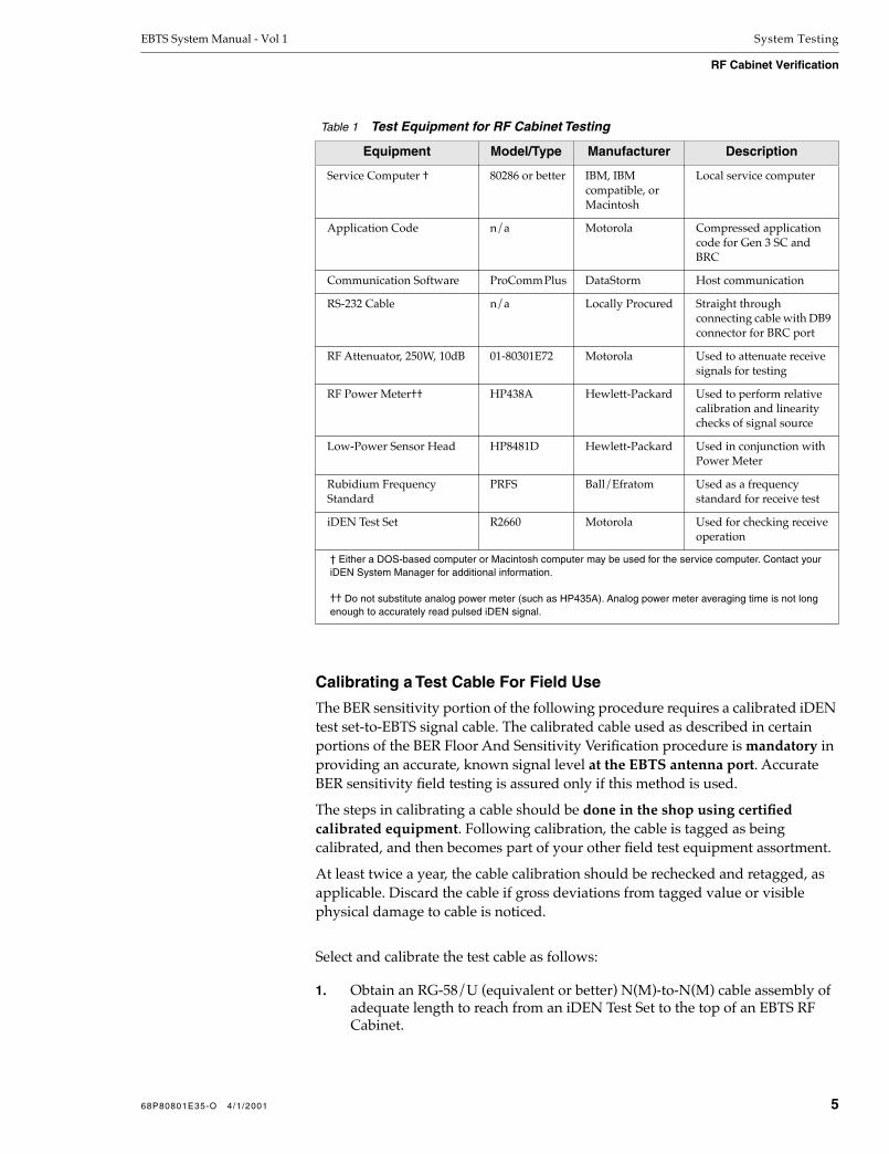
EBTS System Manual - Vol 1 System Testing
RF Cabinet Verification
Calibrating a Test Cable For Field Use
The BER sensitivity portion of the following procedure requires a calibrated iDEN test set-to-EBTS signal cable. The calibrated cable used as described in certain portions of the BER Floor And Sensitivity Verification procedure is mandatory in providing an accurate, known signal level at the EBTS antenna port. Accurate BER sensitivity field testing is assured only if this method is used.
The steps in calibrating a cable should be done in the shop using certified calibrated equipment. Following calibration, the cable is tagged as being calibrated, and then becomes part of your other field test equipment assortment.
At least twice a year, the cable calibration should be rechecked and retagged, as applicable. Discard the cable if gross deviations from tagged value or visible physical damage to cable is noticed.
Select and calibrate the test cable as follows:
1. Obtain an RG-58/U (equivalent or better) N(M)-to-N(M) cable assembly of adequate length to reach from an iDEN Test Set to the top of an EBTS RF Cabinet.
Table 1 Test Equipment for RF Cabinet Testing
Equipment Model/Type Manufacturer Description
Service Computer † 80286 or better IBM, IBM compatible, or Macintosh
Local service computer
Application Code n/a Motorola Compressed application code for Gen 3 SC and BRC
Communication Software ProComm Plus DataStorm Host communication
RS-232 Cable n/a Locally Procured Straight through connecting cable with DB9 connector for BRC port
RF Attenuator, 250W, 10dB 01-80301E72 Motorola Used to attenuate receive signals for testing
RF Power Meter†† HP438A Hewlett-Packard Used to perform relative calibration and linearity checks of signal source
Low-Power Sensor Head HP8481D Hewlett-Packard Used in conjunction with Power Meter
Rubidium Frequency Standard
PRFS Ball/Efratom Used as a frequency standard for receive test
iDEN Test Set R2660 Motorola Used for checking receive operation
† Either a DOS-based computer or Macintosh computer may be used for the service computer. Contact your iDEN System Manager for additional information.
†† Do not substitute analog power meter (such as HP435A). Analog power meter averaging time is not long enough to accurately read pulsed iDEN signal.
68P80801E35-O 4/1/2001 5

System Testing EBTS System Manual - Vol 1
RF Cabinet Verification
2. Connect Power Meter Sensor Head HP8481D, along with Power Meter HP438A, to the R2660 Test Set RF IN/OUT connector.
3. Turn on the R2660. Set R2660 for a continuous unmodulated carrier.
4. Adjust R2660 output level until a reading of –55 dBm is displayed on the power meter. Disconnect the power meter sensor head from R2660.
5. Connect one end of the cable being calibrated to the R2660 RF IN/OUT connector.
6. Connect the power meter sensor head to the other end of the cable.
7. Observe the reading on the power meter.
8. Solving for loss, calculate the cable loss as follows:
(meter reading) – (55 dBm)= Calibrated cable loss
EXAMPLE:(56.7) – (55 dBm)= 1.7 dB cable loss
9. Apply a permanent tag to the cable, noting its calibrated loss. (This calibration value will be required in subsequent field measurement procedures.)
The calibration tag should also include calibration date and your name.
NOTE
The calibrated cable should be treated with care to prevent degrading of calibration. Pack cable separately in protected box or bag, making certain cable is not coiled excessively tight or bent.
If available, plastic end caps for connectors are recommended.
Base Radio Start-up Sequence
The following procedure assumes that the software has been downloaded to the Base Radio from the Gen 3 SC. Refer to Loading the Base Radios in the Gen 3 SC Supplement to this manual for additional information.
1. Connect an RS-232 cable from the service computer to the STATUS connector located on the front of BRC, in sector 1.
6 68P80801E35-O 4/1/2001

EBTS System Manual - Vol 1 System Testing
RF Cabinet Verification
2. Apply power, if the system has been shut down between procedures. (The Base Radios should have power already applied from the System Checkout procedure.)
NOTE
When servicing Base Radios (BRs), in situations where the Control Board or the entire BR is replaced, the Generation 3 Site Controller (Gen 3 SC) will automatically reboot the serviced BR given that the BR has been off-line for a period not less than that stipulated by the “Replacement BRC Accept Timer” (default is 3 minutes). If the BR is turned on prior to the expiration of the “Replacement BRC Accept Timer”, power the BR back down and wait the minimum timer length before turning the BR back on.
3. On the BRC, verify the condition of the LEDs for each Base Radio, as listed in Table 2.
Verify the following LED conditions on the BRC:
• All BRC LEDs flash 3 times upon initial power-up.
• BR LED flashes quickly when BR is waiting for code to be downloaded from Gen 3 SC.
• All BRC LEDs scroll during code downloading process.
• BR LED flashes slowly when BR is de-keyed.
• BR LED is solid when BR is keyed.
4. On the Power Supply module of the Base Radio, verify that the green LED is lit.
Table 2 Base Radio LED Indications
LED Color Normal Indication
BR Green Flashing
PS Red Off
EX Red Off
PA Red Off
CTL Red Off
R1 Red Off
R2 Red Off
R3 Red Off
NOTE: Refer to the Base Radio section of this manual for conditions relating to the LEDs listed above.
68P80801E35-O 4/1/2001 7

System Testing EBTS System Manual - Vol 1
RF Cabinet Verification
Selecting Base Radio Position and Receiver Complement
During equipment setup or when a Base Radio is to be added, MMI is used to:
Set the position of the Base Radio within the RF Cabinet.
Select a particular Base Radio. This is required when assigning transmit and receive frequencies to a particular Base Radio.
Select a receiver complement for a particular Base Radio.
These operations are described below. Refer to the “Software Commands” section of this manual for detailed information on using the MMI commands.
Setting And Accessing Base Radio Position
The set position command programs the position number of where a Base Radio is mounted within a selected RF Cabinet.
Base Radio designation starts from the bottom of the cabinet, with the lowest Base Radio being designated as “1”.
The set position command would also be used in accessing a particular Base Radio for further MMI actions.
Selecting A Receiver Complement For A Base Radio
The set rx_fru_config command sets which receivers should be present in a selected Base Radio. The command has provision for all possible complements of three receivers.
The set rx_mode command selectively enables any combination of individual receivers within a selected Base Radio, while disabling any receiver that was not specifically selected.
Displaying Base Radio Alarms
In the Gen 3 SC procedures, the Base Radios were connected to the Gen 3 SC and received downloaded test software via the BR-Gen 3 SC Ethernet link. If necessary, reset the Base Radio to initiate the code download from the Gen 3 SC.
1. When prompted, type the proper password.
After entering the correct password, the BRC> prompt is displayed on the service computer.
The default password is motorola.
Enter login password:
BRC>
8 68P80801E35-O 4/1/2001

EBTS System Manual - Vol 1 System Testing
RF Cabinet Verification
NOTE
Motorola recommends changing the default password once proper operation of the equipment has been verified. To change the password, contact the Operations and Maintenance Center (OMC) operator on duty.
2. At the BRC> prompt, type: set alarm_reports off
This command disables synchronous alarm reporting.
3. Type: get alarms
This command displays any outstanding alarm conditions. If any alarms are discovered, they are displayed on the service computer as shown in the example:
If no alarms are present during normal operation, this message is displayed:
BRC> set alarm_reports off
set ALARM REPORTS TRACE to OFF in RAM
BRC> get alarms
[brc fru warning]
[external reference failure]
[gps failure]
BRC> get alarms
NO ALARM CONDITIONS DETECTED
68P80801E35-O 4/1/2001 9

System Testing EBTS System Manual - Vol 1
RF Cabinet Verification
Setting Rx and Tx Frequencies
Base Radio frequencies are factory set to a default receive frequency of 806.000 MHz (800 MHz Base Radio) or 896.000 MHz (900 MHz Base Radio) and a default transmit frequency of 851.000 MHz (800 MHz Base Radio) or 935.000 MHz (900 MHz Base Radio).
CAUTION!Do not transmit to an antenna under any circumstance unless those frequencies are licensed.
Perform the following procedure if you know the actual frequencies required. Otherwise, use the default frequencies.
1. At the BRC> prompt, type: dekey
This command stops all RF transmission.
2. Type: set rx_freq XXX.XXXXX to set the receive frequency.
XXX.XXXXX represents the desired 800 MHz or 900 MHz frequency.
800 MHz BR Example:
900 MHz BR Example:
BRC> dekey
XMIT OFF INITIATED
BRC> set rx_freq 806.00000
set RECEIVE FREQUENCY to 806.00000 MHz in RAM
BRC> set rx_freq 896.00000
set RECEIVE FREQUENCY to 896.00000 MHz in RAM
10 68P80801E35-O 4/1/2001

EBTS System Manual - Vol 1 System Testing
RF Cabinet Verification
3. Type set tx_freq XXX.XXXXX to set the transmit frequency.
XXX.XXXXX represents the desired 800 MHz frequency.
800 MHz BR Example:
900 MHz BR Example:
4. Proceed to Checking Receive Operation.
CAUTIONBe sure the dekey command has been issued to all Base Radios in the cabinet to prevent injury while disconnecting and connecting antennas.
Checking Receive Operation Receive operation test procedures must be performed on each Base Radio in the Main and Expansion (if used) RF Cabinets. For each receiver within each Base Radio, perform Bit Error Rate (BER) verification as described in the BER Floor And Sensitivity Verification procedures below.
The test requires the R2660 iDEN Test Set as a signal source, and a calibrated coaxial cable for connecting the R2660 to the antenna ports on the EBTS RF Cabinet.
NOTE
(800 MHz Cavity Combining RFDS only)Prior to performing this procedure, perform the receiver equalization procedure described in the Cavity Combining RFDS section of this manual.
BRC> set tx_freq 851.00000
set TRANSMIT FREQUENCY to 851.00000 MHz in RAM
BRC> set rx_freq 935.00000
set RECEIVE FREQUENCY to 935.00000 MHz in RAM
68P80801E35-O 4/1/2001 11

System Testing EBTS System Manual - Vol 1
RF Cabinet Verification
NOTE
The following procedure requires the use of a calibrated test set-to-EBTS signal cable. Refer to Calibrating a Test Cable For Field Use instructions earlier in this section for information.
NOTE
Throughout the procedures, calculations solving for losses are used. The convention used is that of solving for losses rather than gain. As such, losses are handled as positive numbers and gain as a negative number (“negative” loss). Therefore, signs (+, –) associated with a reading or value are in some cases dropped.For each calculation required, examples are also provided.
BER Floor And Sensitivity Verification (General Instructions)
BER Floor testing verifies basic receiver functionality by verifying the receivers’ ability to achieve a specified minimum BER at a high signal level. BER Sensitivity testing verifies the receivers’ performance by verifying the receivers’ ability to achieve low BER with a low-level signal.
Perform verification as follows:
1. Connect the service computer to the local service port (STATUS connector) of the Base Radio and log on.
The service port connector is located on the front of the BRC module. The default password is motorola.
NOTE
Motorola recommends changing the default password once proper operation of the equipment has been verified. To change the password, contact the Operations and Maintenance Center (OMC) operator on duty.
2. Press the RESET button on the BRC.
12 68P80801E35-O 4/1/2001

EBTS System Manual - Vol 1 System Testing
RF Cabinet Verification
3. At the BRC> prompt, type: dekey
This command stops all RF transmission.
CAUTIONBe sure the dekey command has been issued to all Base Radios in the cabinet to prevent injury or damage to equipment while disconnecting and connecting antennas.
4. Remove power from the R2660 and connect the Rubidium Frequency Standard 10 MHZ OUTPUT to a 10 dB attenuator.
5. Connect the other end of the 10 dB attenuator to the 10 MHZ REFERENCE OSCILLATOR IN/OUT connector on the R2660.
6. Put the R2660 in EXT REF mode.
7. Apply power to the R2660.
NOTE
Refer to the equipment manual provided with the R2660 for further information regarding mode configuration of the unit (Motorola Part No. 68P80309F16).
8. At the BRC> prompt, type: set alarm_reports offThis command disables alarm reporting.
9. At the BRC> prompt, type: get alarmsVerify a report of “no alarms reported”.
10. At the BRC> prompt, type: set sgc off
This command disables the software gain control routine within the Base Radio. Repeat this step for all Base Radios within each of the RF Cabinets at this site.
11. Connect the service computer to the bottom Base Radio (BR1) in the RF Cabinet.
BRC> dekey
XMIT OFF INITIATED
68P80801E35-O 4/1/2001 13

System Testing EBTS System Manual - Vol 1
RF Cabinet Verification
12. At the BRC> prompt, type: get rx_freq
This command displays the receive frequency for the current Base Radio. The message appears as:
800 MHz BR Example:
900 MHz BR Example:
13. Set the R2660 to the receive frequency determined in the previous step.
All receivers within a Base Radio have the same receive frequency.
CAUTION!(800 MHz systems only) If cabinet uses tower-top amplifier DC injectors, make certain injector DC power is disconnected or disabled before proceeding. Damage to R2660 can occur if DC power is not disabled.
NOTE
If system uses DC injectors, test signal connection is to be made through DC injectors.
(900 MHz systems only) A calibrated DC block mustbe inserted between the duplexer antenna port andthe calibrated test cable in the following steps.
BRC> get rx_freq
RECEIVE FREQUENCY is 806.00000 MHz
BRC> get rx_freq
RECEIVE FREQUENCY is 896.00000 MHz
14 68P80801E35-O 4/1/2001

EBTS System Manual - Vol 1 System Testing
RF Cabinet Verification
14. Connect R2660 to cabinet Rx1 antenna input as follows:
800 MHz / 900 MHz Duplexed RFDS:
14.1 Disconnect the antenna cable from the duplexer 1 antenna port on the EBTS Main RF Cabinet.
14.2 (See Figure 1.) Using the Calibrated Test cable, connect the R2660 RF IN/OUT connector to the duplexer 1 antenna port. (On 900 MHz systems, connect a calibrated DC block between the test cable and antenna port.)
800 MHz Cavity Combining RFDS:
14.1 Disconnect the antenna cable from the RX1 antenna port (or top of DC injector, if so equipped) on the EBTS Main RF Cabinet.
14.2 (See Figure 1.) Using the Calibrated Test cable, connect the R2660 RF IN/OUT connector to the RX1 antenna port (or top of DC injector, if so equipped).
Figure 1 EBTS BER Verification Setup
R2660TESTSET
RF IN/OUT
EBTS RFCABINET
BR STATUS
LOCALSERVICE
COMPUTER(LAPTOP PC)
CALIBRATED TEST CABLE (NOTE 1)
RS232
EBTS411011698AJF
NOTES: 1. DO NOT CONNECT UNTIL DIRECTED BY PROCEDURE.
2. ON 900 MHz SYSTEMS, INSERT A CALIBRATED DC BLOCK BETWEEN TEST CABLE AND ANTENNA PORT.
CABINET RXANT PORTS
(NOTE 2)
68P80801E35-O 4/1/2001 15

System Testing EBTS System Manual - Vol 1
RF Cabinet Verification
15. At the BRC> prompt, type: set rx_mode 1
This command enables only antenna/receiver 1 while disabling the remaining antenna/receivers. Repeat this step for all Base Radios within each RF Cabinet at the site.
NOTE
For the following tests, make sure the R2660 is set to the same frequency as displayed by the get rx_freq command.
16. Set the R2660 to generate the 6/1 iDEN test signal.
17. At the BRC> prompt, type: get rssi 1 1000
This commands returns the receive signal strength indication. To pass the BER floor test, the Bit Error Rate must be less than 0.01% (1.0e-02%) for the displayed results.
18. Verify that the RSSI dBm signal strength, for the receiver under test, is -80.0 dBm ± 1.0 dBm. Adjust the R2660 signal output level to get the appropriate RSSI dBm level. The BER floor % value is valid only if the RSSI signal strength is within the limits of -81.0 dBm to -79.0 dBm.
BRC>set rx_mode 1set RECEIVER 1 to ENABLED in RAMset RECEIVER 2 to DISABLED in RAMset RECEIVER 3 to DISABLED in RAM
BRC> get rssi 1 1000Star t ing RSSI monitor for 1 repet i t ions averaged each 1000 repor ts.
Line RSSI1 RSSI2 RSSI3 SGC C I BER Offset Sync Miss
dBm dBm dBm dB dBm dBm % Hz %
---- - - - - - - - - - - - - - - - - - - - - - - - - - - - - - - - - - - - - - - - - - - - - - - - - - - - - - - - - - - -
1 -80.0 -131.5 -131.5 0 -79.2 -121.9 0.000e+00 -5.4 .000e+00
16 68P80801E35-O 4/1/2001

EBTS System Manual - Vol 1 System Testing
RF Cabinet Verification
19. Depending on the system type being tested, adjust R2660 output level for an output level at the end of the cable feeding the EBTS as follows:
19.1 Note the tagged calibrated loss value of the Calibrated Test Cable.
19.2 Calculate the required R2660 output level to produce the required EBTS signal level as follows:
19.3 While observing R2660 Output Level display, set the R2660 for an output level as determined above.
System Type Required Level at cable end
800 MHz Duplexed RFDS –113.5 dBm
900 MHz Duplexed RFDS –114.5 dBm
800 MHz Cavity Combining RFDS –107.5 dBm
800 MHz Duplexed RFDS:
(–113.5 dBm) + Calibrated cable loss= Required R2660 Output Level
EXAMPLE:(–113.5) + (1.7)= –111.8 dBm
900 MHz Duplexed RFDS:
(–114.5 dBm) + Calibrated DC Block loss + Calibrated cable loss= Required R2660 Output Level
EXAMPLE:(–114.5) + (2.0) + (1.7)= –110.8 dBm
800 MHz Cavity Combining RFDS:
(–107.5 dBm) + Calibrated cable loss= Required R2660 Output Level
EXAMPLE:(–107.5) + (1.7)= –105.8 dBm
68P80801E35-O 4/1/2001 17

System Testing EBTS System Manual - Vol 1
RF Cabinet Verification
20. At the BRC> prompt, type: get rssi 2 100
This will generate two lines of printout showing the Bit Error Rate (BER) averaged over 100 readings. Depending on system type, proceed as follows:
For 800 MHz Systems, the Base Radio BER readings must be less than 8% (8.0e - 00%) on each line of the displayed results.
800 MHz Duplexed RFDS Example:
800 MHz Cavity Combining RFDS Example:
For 900 MHz Systems, the Base Radio BER readings must be less than 10% (10.0e - 00%) on each line of the displayed results.
900 MHz Duplexed RFDS Example:
21. Note and record the BER obtained.
BRC> get rssi 2 100
Starting RSSI monitor for 2 repetit ions averaged each 100 reports.
Line RSSI1 RSSI2 RSSI3 SGC DIV BER SyncMiss
dBm dBm dBm dB dBm % %
---- ----- ----- ----- ---- ----- --------- ---------
100 -113.5 0.0 1.942e+00 0.000e+00
200 -113.5 0.0 1.068e+00 0.000e+00
BRC> get rssi 2 100
Starting RSSI monitor for 2 repetit ions averaged each 100 reports.
Line RSSI1 RSSI2 RSSI3 SGC DIV BER SyncMiss
dBm dBm dBm dB dBm % %
---- ----- ----- ----- ---- ----- --------- ---------
100 -107.5 0.0 1.942e+00 0.000e+00
200 -107.5 0.0 1.068e+00 0.000e+00
BRC> get rssi 2 100
Starting RSSI monitor for 2 repetit ions averaged each 100 reports.
Line RSSI1 RSSI2 RSSI3 SGC DIV BER SyncMiss
dBm dBm dBm dB dBm % %
---- ----- ----- ----- ---- ----- --------- ---------
100 -114.5 0.0 1.942e+00 0.000e+00
200 -114.5 0.0 1.068e+00 0.000e+00
18 68P80801E35-O 4/1/2001
EBTS System Manual - Vol 1 System Testing
RF Cabinet Verification
NOTE
If the BER obtained in the above step is equal to or greater than the specified limit, a problem is indicated. Continue with tests in this procedure; the results of the remaining tests will be used in fault-isolating the BER problem.
22. At the BRC > prompt, type: get alarms
This command returns all active alarms of the Base Radio.
NOTE
If the get alarms command displays alarms, refer to the System Troubleshooting section for corrective actions.
23. At the BRC> prompt, type: get rx1_kit_no
This command returns the kit number of the receiver.
800 MHz BR:
900 MHz BR:
BRC> get alarms
NO ALARM CONDITIONS DETECTED
BRC> get rx1_kit_no
RECEIVER 1 KIT NUMBER IS CRF6010A
BRC> get rx1_kit_no
RECEIVER 1 KIT NUMBER IS CRF6030A
68P80801E35-O 4/1/2001 19

System Testing EBTS System Manual - Vol 1
RF Cabinet Verification
NOTE
If the kit number is CRF6010 or CRF6030, continue to step 24. If the kit number is TRF6560, proceed to step 26.
Prompt displays kit numbers (which should not beconfused with FRU numbers). Refer to Base RadioFRUs (Foreword) for correlation between receiver kitnumbers and corresponding FRU numbers.
24. At the BRC> prompt, type: get rx_fru_config
This command lists the receivers active for diversity.
NOTE
If the antenna configuration does not match the receiver configuration, use the set rx_fru_config MMI command to properly set the parameter.
25. Move the service computer to the next Base Radio and repeat steps 17 through 24 of this procedure.
Remember to verify the correct receive frequency for each Base Radio.
26. Reconnect antenna connections as follows:
800 MHz / 900 MHz Duplexed RFDS:
26.1 Disconnect the Calibrated Test Cable from the antenna 1 duplexer.
26.2 Reconnect the antenna cable to the duplexer 1 antenna port.
800 MHz Cavity Combining RFDS:
26.1 Disconnect the Calibrated Test Cable from the RX1 antenna port (or top of DC injector, if so equipped).
26.2 Reconnect the antenna cable to the RX1 antenna port (or top of DC injector, if so equipped).
27. Proceed to BER Verification (Receiver 2) procedure.
BRC> get rx_fru_config
RECEIVER CONFIGURATION RX1 RX2 RX3
20 68P80801E35-O 4/1/2001

EBTS System Manual - Vol 1 System Testing
RF Cabinet Verification
BER Verification (Receiver 2)
The following procedure describes enabling receiver 2 for BER floor and sensitivity testing. Perform this procedure for two branch and three branch diversity sites.
1. Connect R2660 to cabinet Rx2 antenna input as follows:
800 MHz / 900 MHz Duplexed RFDS:
1.1 Disconnect the antenna cable from the duplexer 2 antenna port on the EBTS Main RF Cabinet.
1.2 Using the Calibrated Test cable, connect the R2660 RF IN/OUT connector to the duplexer 2 antenna port. (On 900 MHz systems, connect a calibrated DC block between the test cable and antenna port.)
800 MHz Cavity Combining RFDS:
1.1 Disconnect the antenna cable from the RX2 antenna port (or top of DC injector, if so equipped) on the EBTS Main RF Cabinet.
1.2 Using the Calibrated Test cable, connect the R2660 RF IN/OUT connector to the RX2 antenna port (or top of DC injector, if so equipped).
2. Connect the service computer to the bottom Base Radio (BR1) STATUS connector in the Main RF Cabinet.
3. At the BRC> prompt, type: set rx_mode 2
This command enables only antenna/receiver 2 while disabling the remaining antenna/receivers. Repeat this step for all Base Radios within all RF cabinets at the site.
4. Again connect the service computer to the bottom Base Radio (BR1).
Repeat steps 17 through 25 of the BER Floor And Sensitivity Verification (General Instructions) procedure for each Base Radio in all cabinets at the site.
BRC>set rx_mode 2set RECEIVER 1 to DISABLED in RAMset RECEIVER 2 to ENABLED in RAMset RECEIVER 3 to DISABLED in RAM
68P80801E35-O 4/1/2001 21

System Testing EBTS System Manual - Vol 1
RF Cabinet Verification
5. Reconnect antenna connections as follows:
800 MHz / 900 MHz Duplexed RFDS:
5.1 Disconnect the Calibrated Test Cable from the antenna 2 duplexer.
5.2 Reconnect the antenna cable to the duplexer 2 antenna port.
800 MHz Cavity Combining RFDS:
5.1 Disconnect the Calibrated Test Cable from the RX2 antenna port (or top of DC injector, if so equipped).
5.2 Reconnect the antenna cable to the RX2 antenna port (or top of DC injector, if so equipped).
6. Depending on site receiver diversity, proceed as follows:
• If testing a two branch diversity site, continue with step 7.
• If testing a three branch diversity site, proceed to BER Verification (Receiver 3) procedure.
7. Connect the service computer to the bottom Base Radio (BR1) in the Main RF Cabinet.
8. At the BRC> prompt, type: set rx_mode 12
This command enables receivers 1 and 2 in the Base Radio.
9. At the BRC> prompt, type: set sgc on
This command enables the software gain control routine within the Base Radio.
10. Connect the service computer to the next Base Radio and repeat steps 8 and 9 for each Base Radio in the Main and Expansion RF Cabinets.
11. Disconnect the service computer from the last Base Radio when complete.
BRC>set rx_mode 12set RECEIVER 1 to ENABLED in RAMset RECEIVER 2 to ENABLED in RAMset RECEIVER 3 to DISABLED in RAM
BRC> set sgc on
set SOFTWARE GAIN CONTROL to ENABLED in RAM
22 68P80801E35-O 4/1/2001
EBTS System Manual - Vol 1 System Testing
RF Cabinet Verification
12. Noting the recorded BER sensitivity readings obtained in step 21 of the BER Floor And Sensitivity Verification (General Instructions) procedure for each receiver and each Base Radio, proceed as follows:
• If all BER readings were less than limit specified above, receiver system is OK. Turn off test setup. Disconnect test setup and reconnect any disconnected system antenna cabling.Proceed to Checking Transmit Operation.
• If any BER reading equalled or exceeded the limit specified above, receiver system needs fault isolation.
Proceed to Excessive BER Fault Isolation procedure in the System Troubleshooting section of this manual.
BER Verification (Receiver 3)
The following procedure describes enabling receiver 3 for BER floor and sensitivity testing. This test applies only to three-branch diversity sites.
1. Connect R2660 to cabinet Rx3 antenna input as follows:
800 MHz / 900 MHz Duplexed RFDS:
1.1 Disconnect the antenna cable from the duplexer 3 antenna port on the EBTS Main RF Cabinet.
1.2 Using the Calibrated Test cable, connect the R2660 RF IN/OUT connector to the duplexer 3 antenna port. (On 900 MHz systems, connect a calibrated DC block between the test cable and antenna port.)
800 MHz Cavity Combining RFDS:
1.1 Disconnect the antenna cable from the RX3 antenna port (or top of DC injector, if so equipped) on the EBTS Main RF Cabinet.
1.2 Using the Calibrated Test cable, connect the R2660 RF IN/OUT connector to the RX3 antenna port (or top of DC injector, if so equipped).
2. Connect the service computer to the bottom Base Radio (BR1) STATUS connector in the Main RF Cabinet.
3. At the BRC> prompt, type: set rx_mode 3
This command enables only antenna/receiver 3 while disabling the remaining antenna/receivers. Repeat this step for all Base Radios within all RF cabinets at the site.
BRC>set rx_mode 3set RECEIVER 1 to DISABLED in RAMset RECEIVER 2 to DISABLED in RAMset RECEIVER 3 to ENABLED in RAM
68P80801E35-O 4/1/2001 23

System Testing EBTS System Manual - Vol 1
RF Cabinet Verification
4. Again connect the service computer to the bottom Base Radio (BR1).
Repeat steps 17 through 25 of the BER Floor And Sensitivity Verification (General Instructions) procedure for each Base Radio in all cabinets at the site.
5. Reconnect antenna connections as follows:
800 MHz / 900 MHz Duplexed RFDS:
5.1 Disconnect the Calibrated Test Cable from the antenna 3 duplexer.
5.2 Reconnect the antenna cable to the duplexer 3 antenna port.
800 MHz Cavity Combining RFDS:
5.1 Disconnect the Calibrated Test Cable from the RX3 antenna port (or top of DC injector, if so equipped).
5.2 Reconnect the antenna cable to the RX3 antenna port (or top of DC injector, if so equipped).
6. Connect the service computer to the bottom Base Radio (BR1) in the Main RF Cabinet.
7. At the BRC> prompt, type: set rx_mode 123
This command enables all antennas/receivers in the Base Radio.
8. At the BRC> prompt, type: set sgc on
This command enables the software gain control routine within the Base Radio.
9. Connect the service computer to the next Base Radio and repeat steps 7 and 8 for each Base Radio in all the RF Cabinets at the site.
BRC>set rx_mode 123set RECEIVER 1 to ENABLED in RAMset RECEIVER 2 to ENABLED in RAMset RECEIVER 3 to ENABLED in RAM
BRC> set sgc on
set SOFTWARE GAIN CONTROL to ENABLED in RAM
24 68P80801E35-O 4/1/2001

EBTS System Manual - Vol 1 System Testing
RF Cabinet Verification
10. Noting the recorded BER sensitivity readings obtained in step 21 of the BER Floor And Sensitivity Verification (General Instructions) procedure for each receiver and each Base Radio, proceed as follows:
• If all BER readings were less than limit specified above, receiver system is OK. Turn off test setup. Disconnect test setup and reconnect any disconnected system antenna cabling.Proceed to Checking Transmit Operation.
• If any BER reading equalled or exceeded the limit specified above, the receiver system needs fault isolation.
Proceed to Excessive BER Fault Isolation procedure in the System Troubleshooting section of this manual.
Checking Transmit Operation The following procedures verify transmission from the system antennas.
CAUTION!Do not transmit to an antenna under any circumstance unless those frequencies are licensed.
NOTE
(Cavity Combining RFDS only)Prior to performing this procedure, perform the cavity tuning procedure described in the Cavity Combining RFDS section of this manual.
NOTE
The following steps describe the transmit verification of a 70 W Power Amplifier. If the Base Radio under test contains a 40W or 60W Power Amplifier, substitute 40 or 60 (as applicable) instead of 70 in the following steps.
1. Connect the service computer into the local service port of the bottom Base Radio (BR1) within the RF Cabinet and log on.
68P80801E35-O 4/1/2001 25

System Testing EBTS System Manual - Vol 1
RF Cabinet Verification
2. At the BRC> prompt, type: dekey
This command stops all RF transmission.
CAUTION!This command keys the transmitter. Make sure that transmission only occurs on licensed frequencies or into a dummy load.
Attempting to key a 40W (or 60W) station to an outputpower greater than 40W (or 60W) will damage thePower Amplifier.
3. At the BRC> prompt, type: set tx_power 70
This command sets the transmitter output to 70 Watts.
NOTE
(Cavity Combining RFDS only) The get wattmeter command functions only on Base Radios located in the Main RF Cabinet. The get fwd_pwr, get ref_pwr, and get vswr commands are valid for all Base Radios at the site.
BRC> dekey
completed successfully
BRC> set tx_power 70sett ing t ransmit ter power to 70 watts
TXLIN ATTENUATION is 5.000000
TARGET POWER is 70.00 watts [48.45 dbm]ACTUAL POWER is 56.70 watts [47.54 dbm]POWER WINDOW is 66.85 -> 73.30 watts [48.25 -> 48.65 dbm]TXLIN LEVEL REGISTER REDUCED 83 STEPS [ -3.32 db].TXLIN LEVEL is 0x55
completed successful ly
26 68P80801E35-O 4/1/2001

EBTS System Manual - Vol 1 System Testing
RF Cabinet Verification
4. At the BRC> prompt, type: get fwd_pwr
This command returns the current value of forward power as measured from the RF Power Amplifier.
Verify that the returned value meets the specifications listed in Table 3 or 4 (as applicable).
5. At the BRC> prompt, type: get ref_pwr
This command returns the reflected power value as measured from the RF Power Amplifier.
Verify that the returned value meets the specifications listed in Table 3 or 4 (as applicable).
6. At the BRC> prompt, type: get vswr
This command returns the current Voltage Standing Wave Ratio (VSWR) at the RF Power Amplifier.
Verify that the returned value meets the specifications listed in Table 3 or 4 (as applicable).
NOTE
(Duplexed RFDS only) The get wattmeter command is valid only for Base Radios connected to Power Monitor harness (ALARM connector on rear of Base Radio.
For more information, refer to “RF Cabinet Alarm/Power Monitor Harness Connections” (Cabling Information) in the RF Distribution System section of this manual that applies to the system being tested.
BRC> get fwd_pwrFORWARD POWER is 67 watts [48.3 dbm]
BRC> get ref_pwrREFLECTED POWER is 2 watts [31.9 dbm]
BRC> get vswr
VSWR is 1.4:1
68P80801E35-O 4/1/2001 27

System Testing EBTS System Manual - Vol 1
RF Cabinet Verification
7. At the BRC> prompt, type: get wattmeter
This command returns the current forward and reverse power readings, and calculates the VSWR from the external wattmeter located in the RFDS.
Verify that the returned value meets the specifications listed in Table 3 or 4 (as applicable).
Table 3 Transmit Level Specifications (Duplexed RFDS)
FunctionTolerance
70 W, 800 MHz PA 40 W, 800 MHz PA 60 W, 900 MHz PA
Forward Power Greater than 66 W Greater than 38 W Greater than 58 W
Reflected Power Less than 7 W Less than 6.3 W Less than 6 W
VSWR Less than 2.4:1 Less than 2.4:1 Less than 2.4:1
Wattmeter Forward Power:
800 MHz Duplexed RFDS 0182020V06
900 MHz Duplexed RFDS
Greater than 28.5W(w/ combiner 13 W)
—
Greater than 16 W(w/ combiner 7.5 W)
—
—
Greater than 29 W(w/ combiner 12.4 W)
Wattmeter Reflected Power Less than 4.8 W(w/ combiner 2.2 W)
Less than 2.7 W(w/ combiner 1.3 W)
Less than 5.3 W(w/ combiner 2.3 W)
BRC> get wattmeterFORWARD POWER AT WATTMETER is 38 WattsREFLECTED POWER AT WATTMETER is 0 WattsWATTMETER VSWR is 1.1:1
28 68P80801E35-O 4/1/2001

EBTS System Manual - Vol 1 System Testing
RF Cabinet Verification
Wattmeter Forward Power (Expansion Configurations): (NOTE 1)
800 MHz Duplexed RFDS 0182020V06 (NOTE 2)
800 MHz GEN 4 Duplexed RFDS; 1 BR per antenna
800 MHz GEN 4 Duplexed RFDS; 3 BRs per antenna
800 MHz GEN 4 Duplexed RFDS; 6 BRs per antenna (cascaded combining)
Greater than 5 W
Greater than 33 W
Greater than 9.5 W
Greater than 3.5 W
—
Greater than 19 W
Greater than 5.5 W
Greater than 2 W
—
—
—
—
Wattmeter Reflected Power (Expansion Configurations)
Less than 0.9 W — —
NOTES:
1. External wattmeter (power monitor) readings assume Tx signals within 854-866 MHz range. Within 851-854 MHz Tx range, reading may be up to 1.5 dB lower.
2. 800 MHz Duplexed RFDS (0182020V06 and prior) is no longer available. It has been replaced by the 800 MHz GEN 4 Duplexed RFDS. All information herein regarding 800 MHz Duplexed RFDS (0182020V06 and prior) is for reference only.
Table 4 Transmit Level Specifications (Cavity Combining RFDS)
FunctionTolerance
70 Watt PA 40 Watt PA
Forward Power Greater than 66 Watts Greater than 38 Watts
Reflected Power Less than 7 Watts Less than 6.3 Watts
VSWR Less than 2.4:1 Less than 2.4:1
Wattmeter Forward Power † Greater than 21 Watts Greater than 12 Watts
Wattmeter Reflected Power † Less than 3.5 Watts Less than 2 Watts
† Typical numbers based on the insertion loss of a two channel combiner.
Table 3 Transmit Level Specifications (Duplexed RFDS) (Continued)
FunctionTolerance
70 W, 800 MHz PA 40 W, 800 MHz PA 60 W, 900 MHz PA
68P80801E35-O 4/1/2001 29
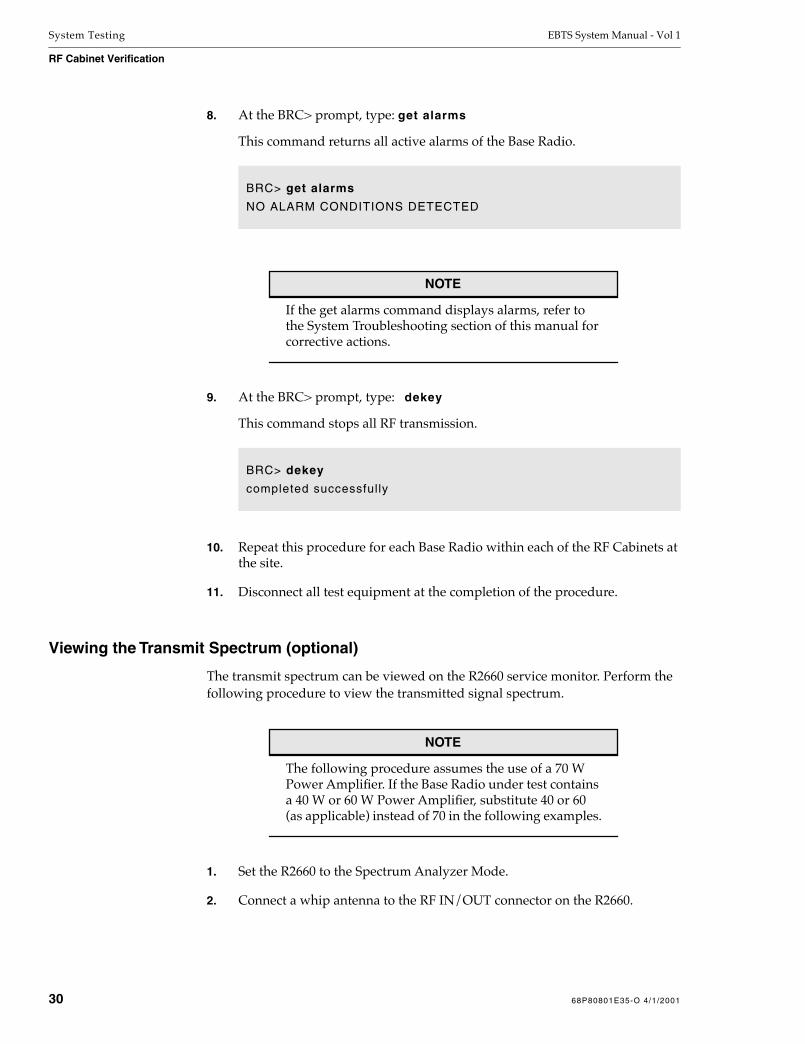
System Testing EBTS System Manual - Vol 1
RF Cabinet Verification
8. At the BRC> prompt, type: get alarms
This command returns all active alarms of the Base Radio.
NOTE
If the get alarms command displays alarms, refer to the System Troubleshooting section of this manual for corrective actions.
9. At the BRC> prompt, type: dekey
This command stops all RF transmission.
10. Repeat this procedure for each Base Radio within each of the RF Cabinets at the site.
11. Disconnect all test equipment at the completion of the procedure.
Viewing the Transmit Spectrum (optional)
The transmit spectrum can be viewed on the R2660 service monitor. Perform the following procedure to view the transmitted signal spectrum.
NOTE
The following procedure assumes the use of a 70 W Power Amplifier. If the Base Radio under test contains a 40 W or 60 W Power Amplifier, substitute 40 or 60 (as applicable) instead of 70 in the following examples.
1. Set the R2660 to the Spectrum Analyzer Mode.
2. Connect a whip antenna to the RF IN/OUT connector on the R2660.
BRC> get alarms
NO ALARM CONDITIONS DETECTED
BRC> dekey
completed successfully
30 68P80801E35-O 4/1/2001

EBTS System Manual - Vol 1 System Testing
RF Cabinet Verification
CAUTION!This command keys the transmitter. Make sure that transmission only occurs on licensed frequencies or into a dummy load.
Attempting to key a 40W (or 60W) station to an outputpower greater than 40W (or 60W) will damage thePower Amplifier.
3. At the BRC> prompt, type: set tx_power 70
This command sets the transmitter output to 70 Watts.
Figure 2 shows the transmitted signal on the Spectrum Analyzer.
4. At the BRC> prompt, type: dekey
This command stops all RF transmission.
5. Repeat this procedure for each Base Radio.
BRC> set tx_power 70sett ing t ransmit ter power to 70 watts
TXLIN ATTENUATION: 5.000000
TARGET POWER: 70.00 watts [48.45 dbm]ACTUAL POWER: 56.70 watts [47.54 dbm]POWER WINDOW: 66.85 -> 73.30 watts [48.25 -> 48.65 dbm]TXLIN LEVEL REGISTER REDUCED 83 STEPS [ -3.32 db].TXLIN LEVEL: 0x55
completed successful ly
BRC> dekey
XMIT OFF INITIATED
68P80801E35-O 4/1/2001 31
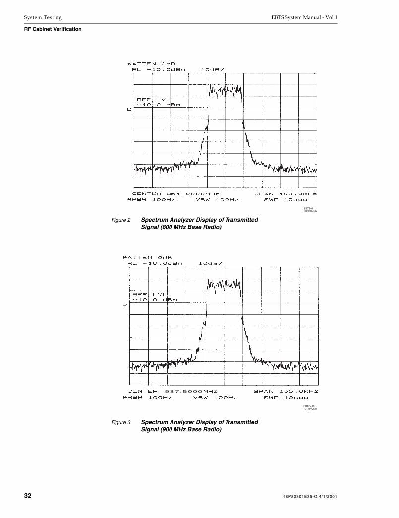
System Testing EBTS System Manual - Vol 1
RF Cabinet Verification
Figure 2 Spectrum Analyzer Display of TransmittedSignal (800 MHz Base Radio)
EBTS071032394JNM
Figure 3 Spectrum Analyzer Display of TransmittedSignal (900 MHz Base Radio)
EBTS071032394JNM
937.5000
EBTS418101797JNM
32 68P80801E35-O 4/1/2001

1 SystemTroubleshooting
Overview
NOTE
In this section, “RF Cabinet” similarly denotes a stand-alone RF cabinet (Stand-Alone Control and RF Cabinet systems) or the RF subsystem of a Single Rack system (Single Rack, Redundant Controller or Single Rack, Single Controller system).
Refer to “EBTS Cabinet Configurations” (System Description section of this manual) for more information about system types and cabinet configurations.
This chapter provides troubleshooting procedures for the RF Cabinet portion of the EBTS.
The topics of this chapter are listed in the following table.
Section Page Description
Base Radio Fault Indications/Isolation
3 Defines the possible failures and corrective actions for failure symptoms of the Base Radio
Excessive BER Fault Isolation
8 Procedure for fault isolating BER faults determined during System Testing
RF Distribution System Fault Isolation
15 Defines the possible failures and corrective actions for failure symptoms of the RF Distribution System
Miscellaneous Troubleshooting
18 Defines the possible failures and corrective actions for miscellaneous failure symptoms
68P80801E35-O 4/1/2001 1Network Solutions Sector
1301 E. Algonquin Road, Schaumburg, IL 60196

System Troubleshooting EBTS System Manual - Vol 1
Troubleshooting
Troubleshooting
The fault indications identified in this chapter provide a guide for isolating failures to a Field Replaceable Unit (FRU).
Perform troubleshooting whenever a failure occurs during normal operation that cannot be resolved by the Operations and Maintenance Center (OMC).
Base Radio Fault Indications
The built-in system troubleshooting intelligence is mainly accessed through the Base Radio(s) LED and Man-Machine Interface (MMI) status and fault indications.
In the event of a failure, the Base Radio indications should always be checked first, in the order set forth in this chapter.
Some indications list several possible failures along with corresponding corrective actions. If a failure is isolated to the FRU level, the suspected module should be replaced with a new one. This restores the system to normal operation as quickly as possible.
Suspected FRUs should be shipped to the appropriate Motorola repair depot for repair.
Base Radio Receiver System Troubleshooting
This section provide procedures for fault-isolating receiver BER faults detected during the “BER Floor and Sensitivity Verification” procedure in the System Testing section of this manual. The procedures in this section can fault-isolate the problem to either a receiver module FRU or other causes within the RFDS.
RF Distribution System Troubleshooting
This section provide procedures for fault-isolating RFDS power failures and alarm indications.
Miscellaneous Troubleshooting
The Miscellaneous Troubleshooting instructions provide a quick reference for solving nonspecific system problems.
2 68P80801E35-O 4/1/2001

EBTS System Manual - Vol 1 System Troubleshooting
Base Radio Fault Indications/Isolation
Base Radio Fault Indications/Isolation
NOTE
MMI commands listed here are Base Radio MMI commands, unless otherwise noted.
NOTE
When servicing Base Radios (BRs), in situations where the Control Board or the entire BR is replaced, the integrated Site Controller (Gen 3 SC) will automatically reboot the serviced BR given that the BR has been off-line for a period not less than that stipulated by the “Replacement BRC Accept Timer” (default is 3 minutes). If the BR is turned on prior to the expiration of the “Replacement BRC Accept Timer”, power the BR back down and wait the minimum timer length before turning the BR back on.
Indication Possible Failure Corrective Action
BR LED (green) is not lit Base Radio (BR) Power Supply module power switch is off
Set power switch to ON position
No power to BR • Verify appropriate breaker is on
• Verify Power Supply switch is on
• Verify power cabling from breaker panel to BR
• Verify power (voltage and polarity) to BR
• Check if Power Amp fans are on
• Check if other LEDs are lit
• Check LEDs on Power Supply
• Check for other alarm conditions by executing get_alarms MMI command
• Replace BR Power Supply module
68P80801E35-O 4/1/2001 3

System Troubleshooting EBTS System Manual - Vol 1
Base Radio Fault Indications/Isolation
BR LED (green) is not lit (continued) BR waiting for registration • Verify Ethernet cabling to Gen 3 SC
• Verify Ethernet properly terminated
• Verify Gen 3 SC successfully downloaded
• Verify proper Ethernet address by executing get enet_id MMI command
• Verify proper cabinet and position settings by executing get_cabinet and get_position MMI command
• Check for other alarm conditions by executing get_alarms MMI command
• Reset BR
• Replace BRC module
BRC/ display board failure • Verify communication through local port
• Check for other alarm conditions by executing get_alarms MMI command
• Reset BR and verify if LEDs initially blink 3 times
• Check ribbon cable between display board and BRC board
• Replace BRC module
BR out of service • Check if other LEDs are lit
• Check for other alarm conditions by executing get_alarms MMI command
• Correct service affecting problem
PS LED (red) is lit Major BR Power Supply alarm • Identify alarm condition by executing get_alarms BR MMI command
• Verify stability and presence of input power
• Verify 28.6 VDC by executing get ps_ad0 MMI command
• Verify 14.2 VDC by executing get ps_ad1 MMI command
• Verify 5.1 VDC by executing get ps_ad2 MMI command
• Replace BR Power Supply module
BRC / display board failure • Verify communication through local port
• Check for other alarm conditions by executing get_alarms MMI command
• Reset BR and verify all LEDs flash 3 times upon power-up
• Check ribbon cable between display board and BRC board
• Replace BRC module
Short circuit on another module • Check for other alarm conditions by executing get_alarms MMI command
• Isolate short circuit by removing other FRUs
• Replace faulty FRU
Indication Possible Failure Corrective Action
4 68P80801E35-O 4/1/2001

EBTS System Manual - Vol 1 System Troubleshooting
Base Radio Fault Indications/Isolation
PS LED (red) is flashing Minor BR Power Supply alarm • Identify alarm condition by executing get_alarms MMI command
• Verify stability and presence of input power
• Replace BR Power Supply module, as required
EX LED (red) is lit Major Exciter alarm • Identify alarm condition by executing get_alarms MMI command
• Verify proper 5 MHz / 1 PPS cabling
• Verify 5 MHz / 1 PPS properly terminated
• Verify correct transmit frequency by executing get tx _freq MMI command
• Verify proper Exciter / PA feedback cabling
• Replace Exciter module
BRC / display board failure • Verify communication through local port
• Check for other alarm conditions by executing get_alarms MMI command
• Reset BR and verify if LEDs initially blink 3 times
• Check ribbon cable between display board and BRC board
• Check BR DSP by executing get tx_sanity MMI command
• Replace BRC module
Receiver module(s) failure • Check if other LEDs are lit
• Check for other alarm conditions by executing get_alarms MMI command
• Verify correct receive frequency by executing get rx_freq MMI command
• Replace Receiver module
Power Amplifier failure • Remove PA and turn on BR
• Check for other (non-PA) alarm conditions
• Replace Power Amplifier module
SRI failure • Verify proper 5 MHz/1 PPS cabling
• Verify 5 MHz/1 PPS is properly terminated
EX LED (red) is flashing Minor Exciter alarm • Identify alarm condition by executing get_alarms MMI command
• Reset the BR
• Replace Exciter module, as required
Indication Possible Failure Corrective Action
68P80801E35-O 4/1/2001 5

System Troubleshooting EBTS System Manual - Vol 1
Base Radio Fault Indications/Isolation
PA LED (red) is lit Major Power Amplifier alarm • Identify alarm condition by executing get_alarms MMI command
• Verify output is properly terminated
• Verify all PA fans are operational
• Verify output cabling integrity
• Replace Power Amplifier module
BRC / display board failure • Verify communication through local port
• Check for other alarm conditions by executing get_alarms MMI command
• Reset BR and verify if LEDs initially blink 3 times
• Check ribbon cable between display board and BRC board
• Replace BRC module
PA LED (red) is flashing Minor Power Amplifier alarm • Identify alarm condition by executing get_alarms MMI command
• PA is in a rollback condition
• Verify proper site environmental conditions
• Verify proper air flow to PA module
• Reset the BR
• Replace the PA, as required
CTL LED (red) is lit Major BRC alarm • Verify communication through local port
• Identify alarm condition by executing get_alarms MMI command
• Verify all external station connections
• Reset the BR and view self test results
• Replace BRC module
BRC display board failure • Verify communication through local port
• Check for other alarm conditions by executing get_alarms MMI command
• Reset BR and verify if LEDs initially blink 3 times
• Check ribbon cable between display board and BRC board
• Replace BRC module
CTL LED (red) is flashing Minor BRC alarm • Identify alarm condition by executing get_alarms MMI command
• Verify all external station connections
• Verify all external station cabling integrity
• Verify 5 MHz / 1 PPS properly terminated
• Verify presence of 5 MHz / 1 PPS
• Replace BRC module, as required
Indication Possible Failure Corrective Action
6 68P80801E35-O 4/1/2001

EBTS System Manual - Vol 1 System Troubleshooting
Base Radio Fault Indications/Isolation
R1, R2, or R3 LED (red) is lit Major Receiver alarm • Identify alarm condition by executing get_alarms MMI command
• Verify proper 5 MHz / 1 PPS cabling
• Verify 5 MHz / 1 PPS properly terminated
• Verify correct receive frequency by executing get rx_freq MMI command
• Verify proper antenna cabling to receiver
• Verify input antenna cabling integrity
• Verify antenna integrity
• Verify RFDS breakers are ON
• Check for RFDS alarms by executing status_eas MMI command
• Reset RFDS fuse(s)
• Replace Receiver module
BRC / display board failure • Verify communication through local port
• Check for other alarm conditions by executing get_alarms MMI command
• Reset BR and verify if LEDs initially blink 3 times
• Check ribbon cable between display board and BRC board
• Check BR DSP by executing get rx_sanity MMI command
• Replace BRC module
R1, R2, or R3 LED (red) is flashing Minor Receiver alarm • Identify alarm condition by executing get_alarms MMI command
• Reset the BR
• Replace 3X Receiver module, as required
Indication Possible Failure Corrective Action
68P80801E35-O 4/1/2001 7

System Troubleshooting EBTS System Manual - Vol 1
Excessive BER Fault Isolation
Excessive BER Fault Isolation
The following procedures fault isolate excessive BER readings between a Base Radio or other receiver system problems. In this manner, the element causing an excessive BER can be isolated through elimination.
Except where noted, this procedure uses the same test setup as shown in Figure 1 in the System Testing section of this manual.
As a general rule, compare the failed BER tests to look for a common failure cause.
If one or more RX branches consistently fail on more than one BR, the problem is most likely related to a common Rx element such as the multicoupler/LNA or cabling common to that particular path. Perform the following:
Check cabling and replace as required.
Check multicoupler/LNA and replace as required.
If excessive BER reading(s) in any number of receivers appear with no common pattern, the fault may be directly related to the corresponding receivers, or to some other element within the receiver system; further testing as provided below is required.
Field Procedure
The procedure below verifies acceptable Base Radio receiver BER and sensitivity. On receiver paths where excessive BER was noted, perform the following procedure.
NOTE
Following any repair or module replacement, the RF Cabinet Verification procedures (System Testing section of this manual) should be repeated on the cabinet(s) where repairs were performed.
1. On receiver where excessive BER was noted, disconnect the Rx cable from the corresponding rear panel RX connector.
2. Connect the Calibrated Test Cable to the RX connector on Base Radio.
3. Connect the service computer to the local service port of the Base Radio and log on.
8 68P80801E35-O 4/1/2001

EBTS System Manual - Vol 1 System Troubleshooting
Excessive BER Fault Isolation
4. Depending on Base Radio (800 or 900 MHz), adjust R2660 output level for an output level at the end of the cable feeding the Base Radio as follows:
4.1 Note the tagged calibrated loss value of the Calibrated Test Cable.
4.2 Calculate the required R2660 output level to produce the required Base Radio signal level as follows:
4.3 While observing R2660 Output Level display, set the R2660 for an output level as determined above.
Base Radio Required Level at cable end
800 MHz –108.0 dBm
900 MHz –109.0 dBm
800 MHz Base Radio:
(–108.0 dBm) + Calibrated cable loss= Required R2660 Output Level
EXAMPLE:(–108.0) + (1.7)= –106.3 dBm
900 MHz Base Radio:
(–109.0 dBm) + Calibrated cable loss= Required R2660 Output Level
EXAMPLE:(–109) + (1.7)= –107.3 dBm
68P80801E35-O 4/1/2001 9

System Troubleshooting EBTS System Manual - Vol 1
Excessive BER Fault Isolation
5. At the BRC> prompt, type: get rssi 2 100
This will generate two lines of printout showing the Bit Error Rate (BER) averaged over 100 readings.
For an 800 MHz Base Radio:
• If BER is greater than 8% (8.0e - 00%), proceed to step 6.
• If BER is 8% (8.0e - 00%) or less, proceed to step 9.
For a 900 MHz Base Radio:
• If BER is greater than 10% (10.0e - 00%), proceed to step 6.
• If BER is 10% (10.0e - 00%) or less, proceed to step 9.
6. Increase the R2260 output level by 2 dB.
7. At the BRC> prompt, again type: get rssi 2 100
BRC> get rssi 2 100
Starting RSSI monitor for 2 repetit ions averaged each 100 reports.
Line RSSI1 RSSI2 RSSI3 SGC DIV BER SyncMiss
dBm dBm dBm dB dBm % %
---- ----- ----- ----- ---- ----- --------- ---------
100 -108.0 0.0 1.942e+00 0.000e+00
200 -108.0 0.0 1.068e+00 0.000e+00
BRC> get rssi 2 100
Starting RSSI monitor for 2 repetit ions averaged each 100 reports.
Line RSSI1 RSSI2 RSSI3 SGC DIV BER SyncMiss
dBm dBm dBm dB dBm % %
---- ----- ----- ----- ---- ----- --------- ---------
100 -109.0 0.0 1.942e+00 0.000e+00
200 -109.0 0.0 1.068e+00 0.000e+00
10 68P80801E35-O 4/1/2001
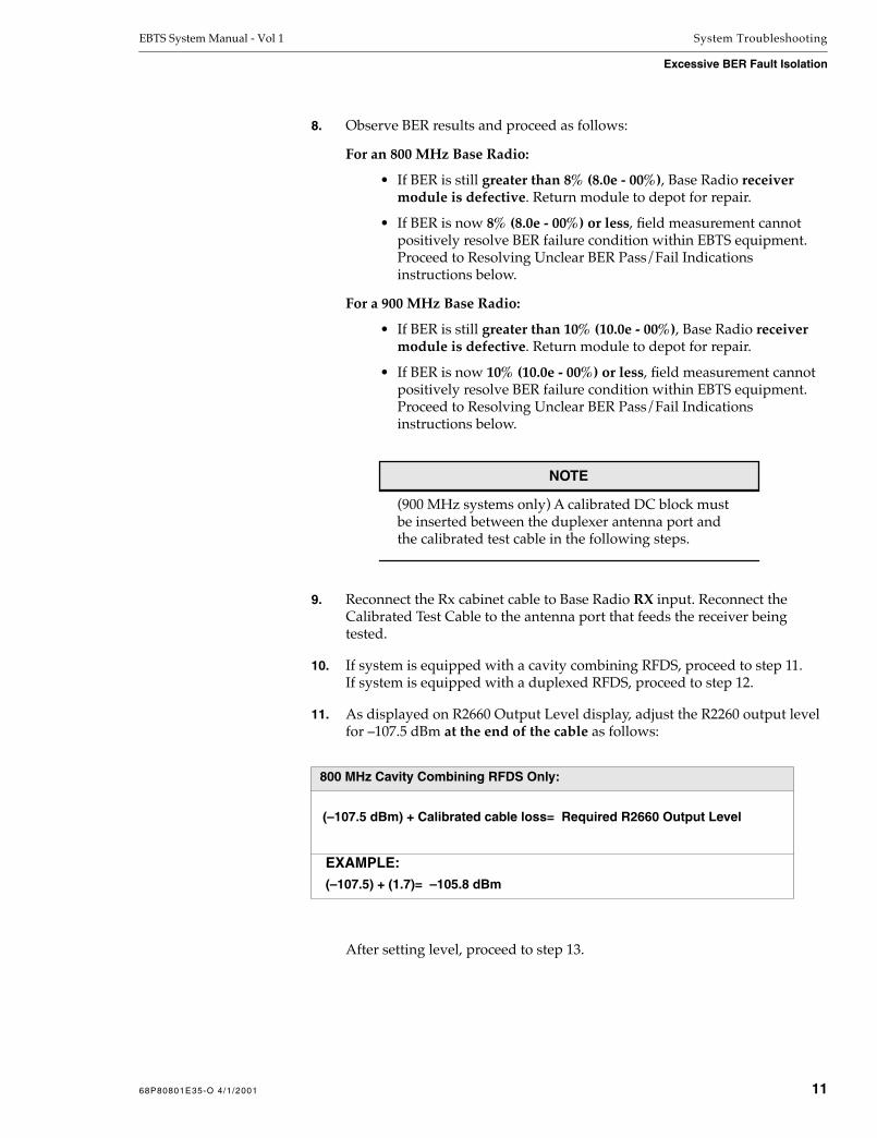
EBTS System Manual - Vol 1 System Troubleshooting
Excessive BER Fault Isolation
8. Observe BER results and proceed as follows:
For an 800 MHz Base Radio:
• If BER is still greater than 8% (8.0e - 00%), Base Radio receiver module is defective. Return module to depot for repair.
• If BER is now 8% (8.0e - 00%) or less, field measurement cannot positively resolve BER failure condition within EBTS equipment. Proceed to Resolving Unclear BER Pass/Fail Indications instructions below.
For a 900 MHz Base Radio:
• If BER is still greater than 10% (10.0e - 00%), Base Radio receiver module is defective. Return module to depot for repair.
• If BER is now 10% (10.0e - 00%) or less, field measurement cannot positively resolve BER failure condition within EBTS equipment. Proceed to Resolving Unclear BER Pass/Fail Indications instructions below.
NOTE
(900 MHz systems only) A calibrated DC block must be inserted between the duplexer antenna port and the calibrated test cable in the following steps.
9. Reconnect the Rx cabinet cable to Base Radio RX input. Reconnect the Calibrated Test Cable to the antenna port that feeds the receiver being tested.
10. If system is equipped with a cavity combining RFDS, proceed to step 11.If system is equipped with a duplexed RFDS, proceed to step 12.
11. As displayed on R2660 Output Level display, adjust the R2260 output level for –107.5 dBm at the end of the cable as follows:
After setting level, proceed to step 13.
800 MHz Cavity Combining RFDS Only:
(–107.5 dBm) + Calibrated cable loss= Required R2660 Output Level
EXAMPLE:(–107.5) + (1.7)= –105.8 dBm
68P80801E35-O 4/1/2001 11

System Troubleshooting EBTS System Manual - Vol 1
Excessive BER Fault Isolation
12. Depending on Base Radio (800 or 900 MHz), adjust R2660 output level for an output level at the end of the cable feeding the EBTS as follows:
After setting level, proceed to next step.
13. At the BRC> prompt, again type: get rssi 2 100
Base Radio Required Level at cable end
800 MHz –111.5 dBm
900 MHz –112.5 dBm
800 MHz Duplexed RFDS:
(–111.5 dBm) + Calibrated cable loss= Required R2660 Output Level
EXAMPLE:(–111.5) + (1.7)= –109.8 dBm
900 MHz Duplexed RFDS:
(–112.5 dBm) + Calibrated DC Block loss + Calibrated cable loss= Required R2660 Output Level
EXAMPLE:(–112.5) + (2.0) + (1.7)= –108.8 dBm
12 68P80801E35-O 4/1/2001

EBTS System Manual - Vol 1 System Troubleshooting
Excessive BER Fault Isolation
14. Observe BER results and proceed as follows:
For an 800 MHz Base Radio:
• If BER is still 8% (8.0e - 00%) or less, field measurement cannot positively resolve BER failure condition within EBTS equipment. Proceed to Resolving Unclear BER Pass/Fail Indications instructions below.
• If BER is now greater than 8% (8.0e - 00%), while other receivers pass without requiring the level increase in step 11 (or 12) above, cabling to the Base Radio RX input should be checked and replaced, as required.
For a 900 MHz Base Radio:
• If BER is still 10% (10.0e - 00%) or less, field measurement cannot positively resolve BER failure condition within EBTS equipment. Proceed to Resolving Unclear BER Pass/Fail Indications instructions below.
• If BER is now greater than 10% (10.0e - 00%), while other receivers pass without requiring the level increase in step 11 (or 12) above, cabling to the Base Radio RX input should be checked and replaced, as required.
Resolving Unclear BER Pass/Fail Indications
In cases where an unclear or marginal pass/fail indications appears (failing at the initial cabinet test signal level, then passing with a small signal level increase), this indicates a functional receive system that is being pulled close to unacceptable BER by one or more reasons. These reasons include:
Several elements within the receive system (RFDS, cabling, and/or receiver module) are within their lower operational pass limits. The cumulative effect of this sometimes results in marginal BER readings, thereby requiring critical test precision and accuracy to rule out testing error as an erroneous cause for rejection.
A problem specific to a site, such as interference.
As in any field situation, the foremost concern is getting the Base Radio up and operational. Perform the following steps to provide immediate corrective action at the field level:
1. Replace the receiver module FRU.
2. Repeat the BER Floor and Sensitivity Verification procedure (System Testing section of this manual).
68P80801E35-O 4/1/2001 13

System Troubleshooting EBTS System Manual - Vol 1
Excessive BER Fault Isolation
3. Depending on the test results, proceed as follows:
• If receive path BER is now OK, no further field actions are required. See Dispositioning of Receiver Modules instructions below.
• If receive path BER still indicates unclear pass/fail indications or failure, the problem is not related to receiver module. Replace the receiver module with the original module and return the second module to spares. Refer to Miscellaneous Troubleshooting instructions in this section.
Dispositioning of Receiver Modules
Before a receiver module is to be returned as “defective”, it is recommended that higher-precision shop testing be performed on the receiver module in accordance with Appendix C – Optional High Precision Receiver BER Testing. The tests in this appendix can positively resolve whether or not a Base Radio receiver module meets factory BER/sensitivity specifications.
This test is also useful in determining the cause of unclear pass/fail indications, as it can positively determine whether or not a receiver module is contributing to a failure.
14 68P80801E35-O 4/1/2001
EBTS System Manual - Vol 1 System Troubleshooting
RF Distribution System Fault Isolation
RF Distribution System Fault Isolation
WARNING!ON GEN 4 DUPLEXED RFDS, COMBINER AND/OR
ISOLATOR DECK SURFACES ARE HOT. CONTACT CAN
CAUSE BURNS. ALLOW DECK SURFACE TO COOL
BEFORE TOUCHING.
Indication Possible Failure Corrective Action
An RF Amplifier resettable fuse (AMP1, AMP2, or AMP3) on the RFDS is tripped
NOTE: Above applies only to 800 MHz Duplexed RFDS 0182020V06 (and prior) and 900 MHz Duplexed RFDS 0183984X01.
Low Noise Amplifier module failure
• Reset the appropriate fuse(s); if it trips again, replace the Low Noise Amplifier module
The POWER SUPPLY LED (green) on the RFDS Power Supply is not lit
NOTE: Above applies only to 800 MHz Duplexed RFDS 0182020V06 (and prior) and 900 MHz Duplexed RFDS 0183984X01.
RFDS Power Supply module failure
• Replace Power Supply module
No power connected to the Power Supply/RFDS
• Check RF Cabinet breakers (RFS1, RFS2)
• Check power cabling to RFDS
RF Cabinet circuit breaker alarm Breaker in RF Cabinet tripped or in OFF position
• Verify that ALL breakers in RF Cabinet are in the ON position
• Identify any tripped breakers and replace faulty FRU, if necessary
• Verify correct breaker panel cabling
Faulty alarm cable • Identify other RF Cabinet alarms by executing display_eas MMI command
• Verify correct alarm cabling
• Verify cabling integrity
• Replace alarm cable, if appropriate
No power to breaker panel • Verify power cabling to the breaker panel
• Verify power (level and polarity) to breaker panel
Breaker panel failure • Verify that ALL breakers in RF Cabinet are in the ON position
• Identify any tripped breakers and replace faulty FRU, if necessary
• Verify correct breaker panel cabling
• Verify power cabling to the breaker panel
• Verify power (level and polarity) to breaker panel
• Replace breaker panel
68P80801E35-O 4/1/2001 15

System Troubleshooting EBTS System Manual - Vol 1
RF Distribution System Fault Isolation
RF Cabinet multicoupler amplifier alarm No power to RFDS • Verify that both breakers for RFS are ON
• Verify either LED on RFDS Power Supply FRU is lit(On GEN 4 and 900 MHz RFDS, verify RFDS power by checking that fans in combiner or isolator deck are operating.)
• Verify power cabling to RFDS
Low noise (multicoupler) amplifier failure
• Check the resettable fuse, reset if necessary
• Replace the low noise amplifier FRU
Tripped or faulty resettable fuse • Check the resettable fuse, reset if necessary
• Replace RFDS, if appropriate
Faulty alarm cable • Identify other RF Cabinet alarms by executing display_eas MMI command
• Verify correct alarm cabling
• Verify cabling integrity
• Replace alarm cable, if appropriate
RF Cabinet multicoupler power supply alarm
RFDS Power Supply FRU failure • Verify that both breakers for RFS are ON
• Verify if Power Supply LEDs are lit.(On GEN 4 and 900 MHz RFDS, verify RFDS power by checking that fans in combiner or isolator deck are operating.)
• Replace RFDS Power Supply FRU
No power to RFDS • Verify that both breakers for RFS are ON
• Verify either green LED on RFDS Power Supply FRU is lit.(On GEN 4 and 900 MHz RFDS, verify RFDS power by checking that fans in combiner or isolator deck are operating.)
• Verify power cabling to RFDS
Faulty alarm cable • Identify other RF Cabinet alarms by executing display_eas MMI command
• Verify correct alarm cabling
• Verify cabling integrity
• Replace alarm cable, if appropriate
Indication Possible Failure Corrective Action
16 68P80801E35-O 4/1/2001

EBTS System Manual - Vol 1 System Troubleshooting
RF Distribution System Fault Isolation
RF Cabinet tower top amplifier alarm No power to RFDS • Verify that both breakers for RFS are ON
• Verify either LED on RFDS Power Supply FRU is lit.(On GEN 4 and 900 MHz RFDS, verify RFDS power by checking that fans in combiner or isolator deck are operating.)
• Verify power cabling to RFDS
Tower top amplifier failure • Verify power to tower top amplifier
• On RFDS Power Supply Tray equipped with Reset switch, actuate Reset switch
• Test functionality of tower top amplifier through test port connection
• Replace tower top amplifier
No power to tower top amplifier • Verify that both breakers for RFS are ON
• Verify either LED on RFDS Power Supply FRU is lit.(On GEN 4 and 900 MHz RFDS, verify RFDS power by checking that fans in combiner or isolator deck are operating.)
• Verify Tower Amp cabling to DC injector
• Verify DC power to Tower Amplifier from the Power Supply Tray
• On RFDS Power Supply Tray equipped with Reset switch, actuate Reset switch
• Verify RF cabling to tower top amplifier
Faulty alarm cable • Identify other RF Cabinet alarms by executing display_eas MMI command
• Verify correct alarm cabling
• Verify cabling integrity
• Replace alarm cable, if appropriate
DC injector failure • Check all DC injectors for short between DC injection port and ground. Replace as required. (This failure is especially evident following a lightning strike.)
Indication Possible Failure Corrective Action
68P80801E35-O 4/1/2001 17

System Troubleshooting EBTS System Manual - Vol 1
Miscellaneous Troubleshooting
Miscellaneous Troubleshooting
Indication Possible Failure Corrective Action
No communication from OMC Open or disconnected T1 line • Check for open or disconnected T1 line
No over-the-air communication Open Ethernet cable, or missing termination of Ethernet cable
• Verify no open or damaged Ethernet cable, or missing termination
Gen 3 SC failure • Refer to Gen 3 SC Supplement manual
Open or damaged BR antenna, lead-in, or surge arrestor
• Verify no open or damaged BR antenna, lead-in or surge arrestor
No internal site communication (Ethernet) Open Ethernet cable, missing termination of Ethernet cable
• Verify no open or damage to Ethernet cable, or missing termination
Gen 3 SC failure • Refer to Gen 3 SC Supplement manual.
Transmissions bad or unusable Open or damaged BR antenna, lead-in, or surge arrestor
• Verify no open or damaged BR antenna, lead-in, or surge arrestor
Marginal receiver system BER • EBTS receive system degradation
• Check RFDS receive hardware (through tests and/or substitution) and replace, as required
NOTE: If problem is common to a certain Rx branch, Rx items in that path should be highly suspected. Check items and replace, as required.
• Base Radio problem • If, through substitution and process of elimination, repeated receiver module replacement on a Base Radio does not solve problem, Base Radio may need repair.
• Interference/spurious response conditions caused by ambient high-level EMI sources (such as radio transmitters or telephony repeaters).
• Analyze field space RF spectrum within site.Correct as required.
Bad VSWR reported Open or damaged BR antenna, lead-in, or surge arrestor
• Verify no open or damage to BR antenna, lead-in, or surge arrestor
Entire site off air after several hours AC Power failure • Verify AC input
Site power supply system alarms Defective rectifier module • (SCRF or SRRC) Check module fault indicator(s), as applicable
• (SRSC) Check for illuminated MODULE ALARM indication on Rectifier Module(s). Replace modules as required.
Improper power supply system threshold settings
• Measure power supply system float and threshold parameters. Adjust as required. (Refer to Final Checkout section of this manual for power supply system checkout and setup.)
NOTE: For SCRF and SRRC systems, power supply system is not part of EBTS. Refer to manufacturer’s data for troubleshooting and maintenance instructions. For SRSC system, refer to “Replacement of AC/DC Power System FRUs” (Single Rack, Single Controller section of this manual) for maintenance instructions.
18 68P80801E35-O 4/1/2001

1 SoftwareCommands
Overview
This section provides definitions for the Man-Machine-Interface (MMI) commands. MMI commands are used to test and configure the EBTS equipment via a service computer. Two command sets are used to accomplish this; the Generation 3 Site Controller (Gen 3 SC) command set and Base Radio (BR) command set.
The Gen 3 SC command set is described in detail in the Gen 3 SC Supplement to this manual. Base radio commands are described herein.
The following table lists the chapter topics.
Section Page Description
MMI Commands 2 Describes the MMI commands, including access levels, and conventions
Base Radio Commands
4 Defines the Base Radio commands used to configure and test the Base Radios
68P80801E35-O 4/1/2001 1Network Solutions Sector
1301 E. Algonquin Road, Schaumburg, IL 60196

Software Commands EBTS System Manual - Vol 1
MMI Commands
MMI Commands
This section describes all MMI commands pertaining to the Base Radios. All valid commands are described, along with the syntax, definitions, and examples.
MMI commands are input from a service computer to the system RS-232 serial port (19200 bps, 8 data bits, 1 stop bit, no parity). The RS-232 is accessed from the iSC, or from the front of each BRC in the RF Cabinet.
The test procedure for the Base Radio uses these commands to test and configure the system. Refer to the Base Radio section of this manual for the Base Radio test procedures.
This section covers Base Radio MMI commands only; refer to the Gen 3 SC Supplement to this manual for a complete description of all MMI commands pertaining to the Gen 3 SC.
Access Level
The Base Radio commands are available through the use of the password: motorola. This password allows the service technician access to a subset of the MMI command set. This subset is used for field service and does not allow permanent configuration of the Base Radio.
NOTE
The motorola password is a default password that is programmed during manufacturing. The password may be changed by the Operations and Maintenance Center (OMC).
Most of the commands are valid only while the Base Radio is in the test mode. The configuration data is temporarily stored in RAM until the Base Radio is taken out of the test mode. Most MMI commands do not allow the configuration data to be permanently stored in EEPROM, although a limited number do. Commands that allow configuration data to be changed are noted.
2 68P80801E35-O 4/1/2001

EBTS System Manual - Vol 1 Software Commands
MMI Commands
Conventions
All Base Radio MMI commands are presented in alphabetical order. The command syntax is case sensitive. The syntax for each command is presented as follows:
plain text shows the actual text to be typed to invoke a command or action
italic text shows where a parameter or value is to be substituted
text enclosed in brackets [ ] indicates an optional value that may be entered.
Where items are separated by vertical bars | , the items are the applicable choices that may be entered
text enclosed in braces indicates a corresponding selection or parameter that must be entered for the command to execute
A series of dots ... indicates one or more occurrences of a preceding parameter
The syntax for the BR commands is case sensitive. Each example is shown in the format that should be entered by the operator.
Some commands require the use of parameters. If input parameters are not entered, a response is returned identifying the proper syntax for the command.
A definition describes in detail each command’s purpose and function. Where helpful, the definition is followed by an example of the commands response. Typical values have been used whenever possible.
Some commands return varying responses (such as available, not available, unknown, o.k., and alarm). Only one of the possible responses is listed in each example.
68P80801E35-O 4/1/2001 3

Software Commands EBTS System Manual - Vol 1
Base Radio Commands
Base Radio Commands
DEKEY
Syntax:dekey
The dekey command stops all RF transmission.
After the command is entered, an indication of a successful transmission stop is returned.
Example:
GET ALARMS
Syntax:get alarms
The get alarms command returns Base Radio alarm conditions.
Example:
If alarm conditions exist, all active alarms are returned.
If no alarm conditions exist, a message is returned indicating alarms have not been detected.
BRC> dekeyXMIT OFF INITIATED
BRC> get alarms[brc fru warning][external reference failure][gps failure]
BRC> get alarmsNO ALARM CONDITIONS DETECTED.
4 68P80801E35-O 4/1/2001

EBTS System Manual - Vol 1 Software Commands
Base Radio Commands
GET ALARM_MASK
Syntax:get alarm_mask
The get alarm_mask command returns twelve, 1-byte hexadecimal fields. These bytes represent which alarms are enabled or disabled.
ff indicates that all alarms covered by that byte are enabled.
Example:
GET ALARM_REPORTS
Syntax:get alarm_reports
The get alarm_reports command returns the enabled/disabled status of the alarm reports.
Example:
GET BRC_KIT_NO
Syntax:get brc_kit_no
The get brc_kit_no command returns the kit number of the Base Radio Controller (BRC) module.
Example:
BRC> get alarm_mask ALARM MASK is |ff|ff|ff|ff|ff|ff|ff|ff|ff|ff|ff|ff|ff|ff|ff|ff|
BRC> get alarm_reports ALARM REPORTS: TRACE is ENABLED
BRC> get brc_kit_noBRC KIT NUMBER is TRN7515A
68P80801E35-O 4/1/2001 5

Software Commands EBTS System Manual - Vol 1
Base Radio Commands
GET BRC_REV_NO
Syntax:get brc_rev_no
The get brc_rev_no command returns the hardware revision number of the BRC module.
Example:
GET BRC_SCRATCH
Syntax:get brc_scratch
The get brc_scratch command reads the allocated EEPROM field reserved for a scratch pad on the BRC module.
Example:
GET CABINET
Syntax:get cabinet
The get cabinet command returns the cabinet in which the current Base Radio resides.
Example:
BRC> get brc_rev_noBRC REVISION NUMBER is RXX.XX.XX
BRC> get brc_scratchBRC SCRATCH is Motorola, Inc.
BRC> get cabinetCABINET is 1
6 68P80801E35-O 4/1/2001

EBTS System Manual - Vol 1 Software Commands
Base Radio Commands
GET DEFAULT_TX_POWER
Syntax:get default_tx_power
The get default_tx_power command returns the default transmit operating power level. The value is returned in Watts and dBm.
800 MHz Base Radio Example:
900 MHz Base Radio Example:
GET ENET_ID
Syntax:get enet_id
The get enet_id command returns the Ethernet address for the current BRC.
Example:
BRC> get default_tx_powerDEFAULT TRANSMITTER POWER is 50.00 watts (46.99 dBm)
BRC> get default_tx_powerDEFAULT TRANSMITTER POWER is 60.00 watts (47.78 dBm)
BRC> get enet_idBRC ETHERNET ADDRESS is 08 00 3E C0 02 C8
68P80801E35-O 4/1/2001 7

Software Commands EBTS System Manual - Vol 1
Base Radio Commands
GET EXCITER_SCALING_FACTOR
Syntax:get exciter_scaling_factor port: 0->11
The get exciter_scaling_factor command returns the scaling factor for a specified Exciter module A/D port.
Example:
GET EXT_REF
Syntax:get ext_ref
The get ext_ref command returns the current enabled/disabled state of phase locking circuit on the BRC.
Example:
BRC> get exciter_scaling_factor 1EXCITER SCALING FACTOR 1 is 1.000000
BRC> get ext_refEXTERNAL REFERENCE is ENABLED
8 68P80801E35-O 4/1/2001
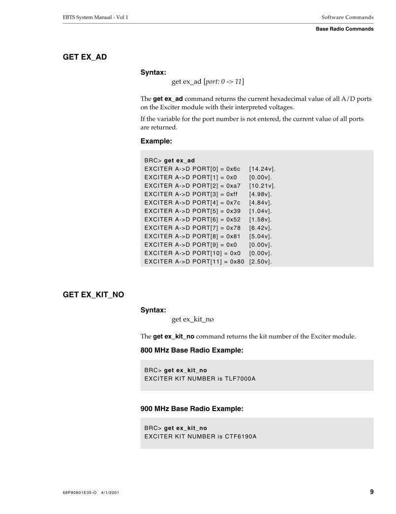
EBTS System Manual - Vol 1 Software Commands
Base Radio Commands
GET EX_AD
Syntax:get ex_ad [port: 0 -> 11]
The get ex_ad command returns the current hexadecimal value of all A/D ports on the Exciter module with their interpreted voltages.
If the variable for the port number is not entered, the current value of all ports are returned.
Example:
GET EX_KIT_NO
Syntax:get ex_kit_no
The get ex_kit_no command returns the kit number of the Exciter module.
800 MHz Base Radio Example:
900 MHz Base Radio Example:
BRC> get ex_adEXCITER A->D PORT[0] = 0x6c [14.24v].EXCITER A->D PORT[1] = 0x0 [0.00v].EXCITER A->D PORT[2] = 0xa7 [10.21v].EXCITER A->D PORT[3] = 0xff [4.98v].EXCITER A->D PORT[4] = 0x7c [4.84v].EXCITER A->D PORT[5] = 0x39 [1.04v].EXCITER A->D PORT[6] = 0x52 [1.58v].EXCITER A->D PORT[7] = 0x78 [6.42v].EXCITER A->D PORT[8] = 0x81 [5.04v].EXCITER A->D PORT[9] = 0x0 [0.00v].EXCITER A->D PORT[10] = 0x0 [0.00v].EXCITER A->D PORT[11] = 0x80 [2.50v].
BRC> get ex_kit_noEXCITER KIT NUMBER is TLF7000A
BRC> get ex_kit_noEXCITER KIT NUMBER is CTF6190A
68P80801E35-O 4/1/2001 9

Software Commands EBTS System Manual - Vol 1
Base Radio Commands
GET EX_REV_NO
Syntax:get ex_rev_no
The get ex_rev_no command returns the hardware revision number of the Exciter module.
Example:
GET EX_SCRATCH
Syntax:get ex_scratch
The get ex_scratch command reads the allocated EEPROM field reserved for the scratch pad on the Exciter module.
Example:
BRC> get ex_rev_noEXCITER REVISION NUMBER is Rxx.xx.xx
BRC> get ex_scratchEXCITER SCRATCH is Motorola, Inc.
10 68P80801E35-O 4/1/2001
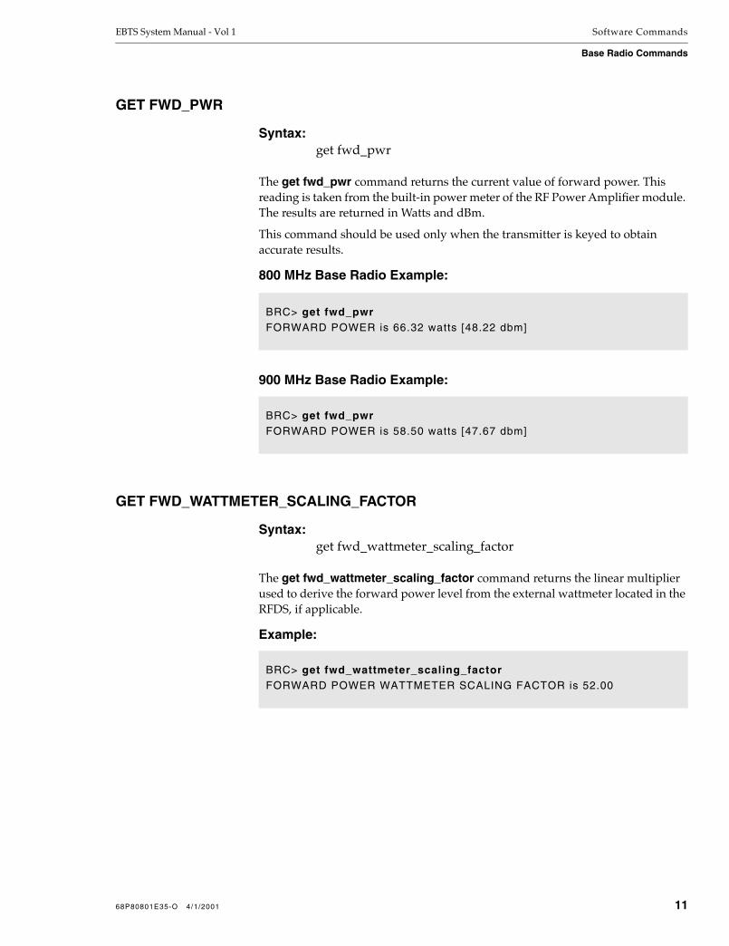
EBTS System Manual - Vol 1 Software Commands
Base Radio Commands
GET FWD_PWR
Syntax:get fwd_pwr
The get fwd_pwr command returns the current value of forward power. This reading is taken from the built-in power meter of the RF Power Amplifier module. The results are returned in Watts and dBm.
This command should be used only when the transmitter is keyed to obtain accurate results.
800 MHz Base Radio Example:
900 MHz Base Radio Example:
GET FWD_WATTMETER_SCALING_FACTOR
Syntax:get fwd_wattmeter_scaling_factor
The get fwd_wattmeter_scaling_factor command returns the linear multiplier used to derive the forward power level from the external wattmeter located in the RFDS, if applicable.
Example:
BRC> get fwd_pwrFORWARD POWER is 66.32 watts [48.22 dbm]
BRC> get fwd_pwrFORWARD POWER is 58.50 watts [47.67 dbm]
BRC> get fwd_wattmeter_scaling_factorFORWARD POWER WATTMETER SCALING FACTOR is 52.00
68P80801E35-O 4/1/2001 11

Software Commands EBTS System Manual - Vol 1
Base Radio Commands
GET K_FACTOR
Syntax:get k_factor
The get k_factor command returns the current operational k_factor value.
Example:
GET MAX_VSWR
Syntax:get max_vswr
The get max_vswr command returns the maximum Voltage Standing Wave Ratio (VSWR) before an alarm is triggered, as measured by the external wattmeter located in the RFDS, if applicable.
Example:
GET MAX_WATTMETER_VSWR
Syntax:get max_wattmeter_vswr
The get max_wattmeter_vswr command returns the maximum VSWR before an alarm is triggered, as measured by the built-in power meters of the RF Power Amplifier module.
Example:
BRC> get k_factorK FACTOR is 0.85000000
BRC>get max_vswrMAXIMUM VSWR is 4.00:1
BRC>get max_wattmeter_vswrMAXIMUM VSWR AT WATTMETER: 4.00:1
12 68P80801E35-O 4/1/2001

EBTS System Manual - Vol 1 Software Commands
Base Radio Commands
GET PA_AD
Syntax:get pa_ad [port: 0 -> 11]
The get pa_ad command returns the current hexadecimal value of all A/D ports on the Power Amplifier module with their interpreted voltages.
If the variable for the port number is not entered, the current value of all ports are returned.
Example:
BRC> get pa_adPA A->D PORT[0] = 0x0 [0.00v].PA A->D PORT[1] = 0x0 [0.00v].PA A->D PORT[2] = 0x2 [0.04v].PA A->D PORT[3] = 0x7b [2.40v].PA A->D PORT[4] = 0xb [0.21v].PA A->D PORT[5] = 0xb [0.21v].PA A->D PORT[6] = 0x6 [0.06v].PA A->D PORT[7] = 0x8 [0.06v].PA A->D PORT[8] = 0xb [0.21v].PA A->D PORT[9] = 0x80 [2.50v].PA A->D PORT[10] = 0x8 [0.06v].PA A->D PORT[11] = 0x80 [2.50v].
68P80801E35-O 4/1/2001 13

Software Commands EBTS System Manual - Vol 1
Base Radio Commands
GET PA_COEF
Syntax:get pa_coef
The get pa_coef command returns the Power Amplifier coefficients. These values are determined and programmed during manufacturing.
800 MHz Base Radio Example:
900 MHz Base Radio Example:
BRC> get pa_coef***AT AND BELOW 858.500 MHz***PA COEFFICIENT FACTOR A: 0.04900PA COEFFICIENT FACTOR B: 3.04000PA COEFFICIENT FACTOR C: 3.66000
***ABOVE 858.500 MHz***PA COEFFICIENT FACTOR D: 0.00300PA COEFFICIENT FACTOR E: 3.37000PA COEFFICIENT FACTOR F: 3.73000PA TEMPERATURE COEFFICIENT:
BRC> get pa_coef***AT AND BELOW 937.500 MHz***PA COEFFICIENT FACTOR A: 0.04900PA COEFFICIENT FACTOR B: 3.04000PA COEFFICIENT FACTOR C: 3.66000
***ABOVE 937.500 MHz***PA COEFFICIENT FACTOR D: 0.00300PA COEFFICIENT FACTOR E: 3.37000PA COEFFICIENT FACTOR F: 3.73000PA TEMPERATURE COEFFICIENT:
14 68P80801E35-O 4/1/2001

EBTS System Manual - Vol 1 Software Commands
Base Radio Commands
GET PA_KIT_NO
Syntax:get pa_kit_no
The get pa_kit_no command returns the kit number of the Power Amplifier module.
800 MHz Base Radio Example:
900 MHz Base Radio Example:
GET PA_REV_NO
Syntax:get pa_rev_no
The get pa_rev_no command returns the hardware revision number of the Power Amplifier module.
Example:
GET PA_SCALING_FACTOR
Syntax:get pa_scaling_factor port: 0->11
The get pa_scaling_factor command returns the scaling factor for a specified Power Amplifier module A/D port.
Example:
BRC> get pa_kit_noPOWER AMPLIFIER KIT NUMBER is TRN7713A
BRC> get pa_kit_noPOWER AMPLIFIER KIT NUMBER is CLF1300A
BRC> get pa_rev_noPOWER AMPLIFIER REVISION NUMBER is RXX.XX.XX
BRC> get pa_scaling_factor 1POWER AMPLIFIER SCALING FACTOR 1 is 1.000000
68P80801E35-O 4/1/2001 15

Software Commands EBTS System Manual - Vol 1
Base Radio Commands
GET PA_SCRATCH
Syntax:get pa_scratch
The get pa_scratch command reads the allocated EEPROM field reserved for the scratch pad on the Power Amplifier module.
Example:
GET PCTRL
Syntax:get pctrl
The get pctrl command returns the current enabled/disabled state of the power leveling functionality of the Base Radio.
Example:
GET PEND
Syntax:get pend
The get pend command returns the current warp value setting and the internal temperature of the pendulum IC.
Example:
BRC> get pa_scratchPOWER AMPLIFIER SCRATCH PAD is Motorola, Inc.
BRC> get pctrlPOWER CONTROL is ENABLED
BRC> get pendPENDULUM WARP is 0x94PENDULUM TEMPERATURE is +33 C
16 68P80801E35-O 4/1/2001

EBTS System Manual - Vol 1 Software Commands
Base Radio Commands
GET PEND_LOCK
Syntax:get pend_lock
The get pend_lock command returns the current locked/unlocked status of the pendulum lock bit.
Example:
GET POSITION
Syntax:get position
The get position command returns the position number of where the current Base Radio is mounted within a selected cabinet. This does not represent the cabinet in which the Base Radio resides.
Example:
BRC> get pend_lockPENDULUM is LOCKED
BRC> get positionPOSITION is 2
68P80801E35-O 4/1/2001 17

Software Commands EBTS System Manual - Vol 1
Base Radio Commands
GET PS_AD
Syntax:get ps_ad [port: 0 -> 11]
The get ps_ad command returns the current hexadecimal value of all A/D ports on the Power Supply module with their interpreted voltages.
If the variable for the port number is not entered, the current value of all ports are returned.
Example:
GET REF_PWR
Syntax:get ref_pwr
The get ref_pwr command returns the current value of reflected power. This reading is taken from the built-in power meter of the RF Power Amplifier module. The results are returned in Watts and dBm.
This command should only be used when the transmitter is keyed to obtain accurate results.
Example:
BRC> get ps_adPWR SUPPLY A->D PORT[0] = 0xed [28.28v].PWR SUPPLY A->D PORT[1] = 0xe3 [14.23v].PWR SUPPLY A->D PORT[2] = 0xd6 [5.08v].PWR SUPPLY A->D PORT[3] = 0xea [4.57v].PWR SUPPLY A->D PORT[4] = 0x5 [0.10v].PWR SUPPLY A->D PORT[5] = 0xde [4.34v].PWR SUPPLY A->D PORT[6] = 0x92 [2.83v].PWR SUPPLY A->D PORT[7] = 0xff [4.98v].PWR SUPPLY A->D PORT[8] = 0xfe [4.90v].PWR SUPPLY A->D PORT[9] = 0xff [4.98v].PWR SUPPLY A->D PORT[10] = 0x0 [0.00v].PWR SUPPLY A->D PORT[11] = 0x80 [2.46v].
BRC> get ref_pwrREFLECTED POWER is 1.50 watts [31.75 dbm]
18 68P80801E35-O 4/1/2001

EBTS System Manual - Vol 1 Software Commands
Base Radio Commands
GET REF_WATTMETER_SCALING_FACTOR
Syntax:get ref_wattmeter_scaling_factor
The get ref_wattmeter_scaling_factor command returns the linear multiplier used to derive the reflected power level from the external wattmeter located in the RFDS, if applicable.
Example:
GET ROM_VER
Syntax:get rom_ver
The get rom_ver command returns the current software version stored in firmware on the BRC module.
Example:
GET RPTR_STATUS
Syntax:get rptr_status
The get rptr_status command returns the overall status of the repeater.
BRC> get ref_wattmeter_scaling_factorREFLECTED POWER WATTMETER SCALING FACTOR is 52.00
BRC> get rom_verBRC ROM VERSION is RXX.XX.XX
68P80801E35-O 4/1/2001 19
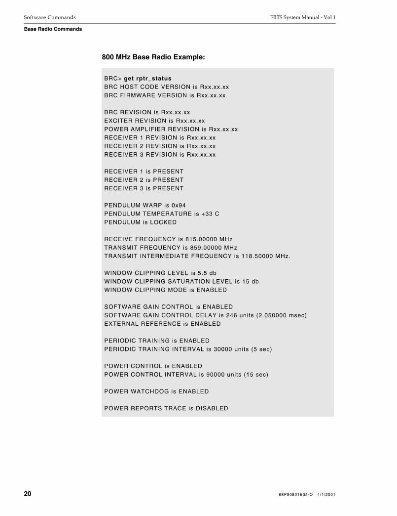
Software Commands EBTS System Manual - Vol 1
Base Radio Commands
800 MHz Base Radio Example:
BRC> get rptr_statusBRC HOST CODE VERSION is Rxx.xx.xxBRC FIRMWARE VERSION is Rxx.xx.xx
BRC REVISION is Rxx.xx.xxEXCITER REVISION is Rxx.xx.xxPOWER AMPLIFIER REVISION is Rxx.xx.xxRECEIVER 1 REVISION is Rxx.xx.xxRECEIVER 2 REVISION is Rxx.xx.xxRECEIVER 3 REVISION is Rxx.xx.xx
RECEIVER 1 is PRESENTRECEIVER 2 is PRESENTRECEIVER 3 is PRESENT
PENDULUM WARP is 0x94PENDULUM TEMPERATURE is +33 CPENDULUM is LOCKED
RECEIVE FREQUENCY is 815.00000 MHzTRANSMIT FREQUENCY is 859.00000 MHzTRANSMIT INTERMEDIATE FREQUENCY is 118.50000 MHz.
WINDOW CLIPPING LEVEL is 5.5 dbWINDOW CLIPPING SATURATION LEVEL is 15 dbWINDOW CLIPPING MODE is ENABLED
SOFTWARE GAIN CONTROL is ENABLEDSOFTWARE GAIN CONTROL DELAY is 246 units (2.050000 msec)EXTERNAL REFERENCE is ENABLED
PERIODIC TRAINING is ENABLEDPERIODIC TRAINING INTERVAL is 30000 units (5 sec)
POWER CONTROL is ENABLEDPOWER CONTROL INTERVAL is 90000 units (15 sec)
POWER WATCHDOG is ENABLED
POWER REPORTS TRACE is DISABLED
20 68P80801E35-O 4/1/2001

EBTS System Manual - Vol 1 Software Commands
Base Radio Commands
900 MHz Base Radio Example:
BRC> get rptr_statusBRC HOST CODE VERSION is Rxx.xx.xxBRC FIRMWARE VERSION is Rxx.xx.xx
BRC REVISION is Rxx.xx.xxEXCITER REVISION is Rxx.xx.xxPOWER AMPLIFIER REVISION is Rxx.xx.xxRECEIVER 1 REVISION is Rxx.xx.xxRECEIVER 2 REVISION is Rxx.xx.xxRECEIVER 3 REVISION is Rxx.xx.xx
RECEIVER 1 is PRESENTRECEIVER 2 is PRESENTRECEIVER 3 is PRESENT
PENDULUM WARP is 0x94PENDULUM TEMPERATURE is +33 CPENDULUM is LOCKED
RECEIVE FREQUENCY is 898.00000 MHzTRANSMIT FREQUENCY is 937.00000 MHzTRANSMIT INTERMEDIATE FREQUENCY is 90.30000 MHz.
WINDOW CLIPPING LEVEL is 5.5 dbWINDOW CLIPPING SATURATION LEVEL is 15 dbWINDOW CLIPPING MODE is ENABLED
SOFTWARE GAIN CONTROL is ENABLEDSOFTWARE GAIN CONTROL DELAY is 246 units (2.050000 msec)EXTERNAL REFERENCE is ENABLED
PERIODIC TRAINING is ENABLEDPERIODIC TRAINING INTERVAL is 30000 units (5 sec)
POWER CONTROL is ENABLEDPOWER CONTROL INTERVAL is 90000 units (15 sec)
POWER WATCHDOG is ENABLED
POWER REPORTS TRACE is DISABLEDALARM REPORTS TRACE is DISABLED
68P80801E35-O 4/1/2001 21

Software Commands EBTS System Manual - Vol 1
Base Radio Commands
GET RSSI
Syntax: get rssi no. of reports no. of samples
The get rssi command allows examination of the received RF signal quality of the Base Radio. A performance report is returned including Bit Error Rate (BER), Received Signal Strength Indication (RSSI), frequency offset, and the sync miss rate.
RSSI data is calculated for the specified number of samples. Each sample is averaged over the specified number of reports specified. A report is generated once every 90 msec.
Example:
BRC> get rssi 2 100Starting RSSI monitor for 2 repetitions averaged each 100 reports.
Line RSSI1 RSSI2 RSSI3 SGC DIV BER SyncMissdBm dBm dBm dB dBm % %
---- ----- ----- ----- ---- ----- --------- ---------1 -109.1 -127.0 -127.0 0.0 -109.0 2.942e+00 0.000e+002 -108.7 -127.0 -127.0 0.0 -109.0 2.874e+00 0.000e+00
22 68P80801E35-O 4/1/2001

EBTS System Manual - Vol 1 Software Commands
Base Radio Commands
GET RX(n)_AD
Syntax:get rx1_ad [port: 0 -> 11]
get rx2_ad [port: 0 -> 11]
get rx3_ad [port: 0 -> 11]
The get rx(n)_ad command returns the current hexadecimal value of all A/D ports on the Receiver module with their interpreted voltages.
If the variable for the port number is not entered, the current value of all ports are returned.
Example:
GET RX(n)_DELTA
Syntax:get rx1_delta
get rx2_delta
get rx3_delta
The get rx(n)_delta command returns the contents of the RSSI offset value in dBm for a selected receiver. This is a calibrated value that is set during manufacturing.
Example:
BRC> get rx1_adRX1 A->D PORT[0] = 0xe0 [9.71v].RX1 A->D PORT[1] = 0x87 [5.27v].RX1 A->D PORT[2] = 0xe2 [9.80v].RX1 A->D PORT[3] = 0xff [4.98v].RX1 A->D PORT[4] = 0x7d [4.88v].RX1 A->D PORT[5] = 0xe6 [4.49v].RX1 A->D PORT[6] = 0x57 [1.70v].RX1 A->D PORT[7] = 0x67 [2.01v].RX1 A->D PORT[8] = 0x7d [4.88v].RX1 A->D PORT[9] = 0xd0 [8.13v].RX1 A->D PORT[10] = 0x64 [1.95v].
BRC> get rx1_deltaRECEIVER 1 RECEIVE SIGNAL STRENGTH DELTA is 0.0
68P80801E35-O 4/1/2001 23

Software Commands EBTS System Manual - Vol 1
Base Radio Commands
GET RX(n)_KIT_NO
Syntax:get rx1_kit_no
get rx2_kit_no
get rx3_kit_no
The get rx(n)_kit_no command returns the kit number of a selected Receiver module.
800 MHz Base Radio Example:
900 MHz Base Radio Example:
GET RX(n)_REV_NO
Syntax:get rx1_rev_no
get rx2_rev_no
get rx3_rev_no
The get rx(n)_rev_no command returns the hardware revision number of the specified Receiver module.
Example:
BRC> get rx1_kit_noRECEIVER 1 KIT NUMBER is CRF6010A
BRC> get rx1_kit_noRECEIVER 1 KIT NUMBER is CRF6030A
BRC> get rx1_rev_noRECEIVER 1 REVISION NUMBER is RXX.XX.XX
24 68P80801E35-O 4/1/2001

EBTS System Manual - Vol 1 Software Commands
Base Radio Commands
GET RX(n)_SCALING_FACTOR
Syntax:get rx1_scaling_factor port: 0 -> 11
get rx2_scaling_factor port: 0 -> 11
get rx3_scaling_factor port: 0 -> 11
The get rx(n)_scaling_factor command returns the scaling factor for a specified Receiver module A/D port.
Example:
GET RX(n)_SCRATCH
Syntax:get rx1_scratch
get rx2_scratch
get rx3_scratch
The get rx(n)_scratch command reads the allocated EEPROM field reserved for the scratch pad on the specified Receiver module.
Example:
BRC> get rx1_scaling_factor 1RECEIVER 1 SCALING FACTOR 1 is 2.000000
BRC> get rx1_scratchRECEIVER 1 SCRATCH is Motorola, Inc.
68P80801E35-O 4/1/2001 25

Software Commands EBTS System Manual - Vol 1
Base Radio Commands
GET RX_FREQ
Syntax: get rx_freq
The get rx_freq command returns the programmed receiver frequency for the current Base Radio.
800 MHz Base Radio Example:
900 MHz Base Radio Example:
GET RX_FRU_CONFIG
Syntax:get rx_fru_config
The get rx_fru_config displays the current receiver diversity configuration of a Base Radio.
Example:
BRC>get rx_freqThe RX FREQUENCY is: 806.00000 MHz
BRC>get rx_freqThe RX FREQUENCY is: 896.00000 MHz
BRC> get rx_fru_configRECEIVER CONFIGURATION RX1 RX2 RX3
26 68P80801E35-O 4/1/2001

EBTS System Manual - Vol 1 Software Commands
Base Radio Commands
GET RX_INJ
Syntax: get rx_inj
The get rx_inj command returns the high/low side injection status of the second Local Oscillator (LO) for all receivers.
Example:
GET RX_MODE
Syntax: get rx_mode
The get rx_mode command returns the enabled/disabled status of the receiver.
Example:
GET RX_QSIGN
Syntax:get rx_qsign
The get rx_qsign command returns the current Q sign status of the receivers.
Example:
BRC> get rx_injRECEIVER INJECTION is LOW
BRC>get rx_modeRECEIVER 1 is ENABLEDRECEIVER 2 is ENABLEDRECEIVER 3 is ENABLED
BRC> get rx_qsignRECEIVER Q SIGN is NON-INVERTED
68P80801E35-O 4/1/2001 27

Software Commands EBTS System Manual - Vol 1
Base Radio Commands
GET RX_SANITY
Syntax:get rx_sanity
The get rx_sanity command returns the receive Digital Signal Processor (DSP) operational condition as either passed or failed.
Example:
GET RX_STATUS
Syntax:get rx_status
The get rx_status command returns status information of the receivers.
Example:
GET RX_VERSION
Syntax:get rx_version
The get rx_version command returns the current RX Digital Signal Processor (DSP) software version.
Example:
BRC> get rx_sanityRECEIVE DSP SANITY TEST passed
BRC> get rx_statusRECEIVER INJECTION is LOWBER STATUS is LOCKEDRECEIVER Q SIGN is NON-INVERTEDRECEIVER 1 is ENABLEDRECEIVER 2 is ENABLEDRECEIVER 3 is ENABLED
BRC> get rx_versionRECEIVE DSP VERSION is 251.235
28 68P80801E35-O 4/1/2001

EBTS System Manual - Vol 1 Software Commands
Base Radio Commands
GET SGC
Syntax:get sgc
The get sgc command returns the enabled/disabled status of the Software Gain Control (SGC) routine.
Example:
GET SGC_ATTEN
Syntax:get sgc_atten no. of repetitions: 1->10,000
The get sgc_atten command returns the attenuator values as reported from the Digital Signal Processor (DSP) to the screen for the number of repetitions specified.
Example:
BRC> get sgcSOFTWARE GAIN CONTROL is ENABLED
BRC> get sgc_atten 10Starting SGC monitor for 10 repetit ionsdisplays hex number of 2-dB attenuation steps 0 0 0 0 0 0 0 0 0 0 0 0 0 0 0 0 0 0 0 0 0 0 0 0 0 0 0 0 0 0 0 0 0 0 0 0 0 0 0 0 0 0 0 0 0 0 0 0 0 0 0 0 0 0 0 0 0 0 0 0
68P80801E35-O 4/1/2001 29
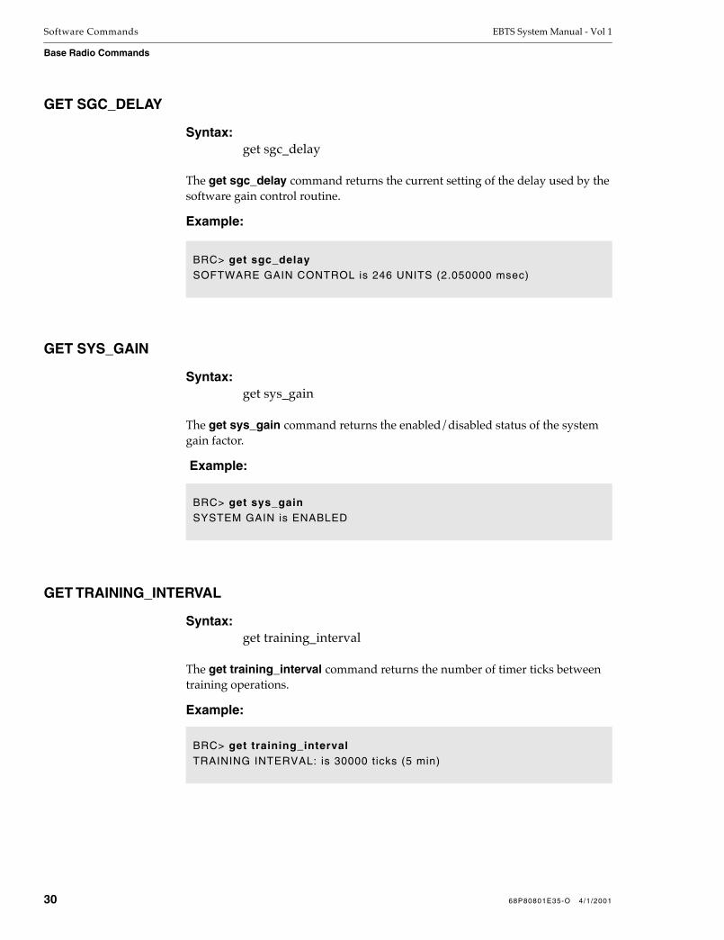
Software Commands EBTS System Manual - Vol 1
Base Radio Commands
GET SGC_DELAY
Syntax:get sgc_delay
The get sgc_delay command returns the current setting of the delay used by the software gain control routine.
Example:
GET SYS_GAIN
Syntax:get sys_gain
The get sys_gain command returns the enabled/disabled status of the system gain factor.
Example:
GET TRAINING_INTERVAL
Syntax:get training_interval
The get training_interval command returns the number of timer ticks between training operations.
Example:
BRC> get sgc_delaySOFTWARE GAIN CONTROL is 246 UNITS (2.050000 msec)
BRC> get sys_gainSYSTEM GAIN is ENABLED
BRC> get training_intervalTRAINING INTERVAL: is 30000 ticks (5 min)
30 68P80801E35-O 4/1/2001

EBTS System Manual - Vol 1 Software Commands
Base Radio Commands
GET TXLIN
Syntax:get txlin [register: 0x00 -> 0x1a]
The get txlin command returns the corresponding byte of the tranlin register as mapped into memory.
Example:
GET TXLIN_STAT
Syntax:get txlin_stat
The get txlin_stat command returns the tranlin operational status. The unassigned internal registers with dummy data are polled.
Example:
BRC> get txlinTXLIN[0x00]: 0x56 TXLIN[0x01]: 0x08TXLIN[0x02]: 0x16TXLIN[0x03]: 0x29 TXLIN[0x04]: 0xF1TXLIN[0x05]: 0x1ETXLIN[0x06]: 0x2C TXLIN[0x07]: 0x00TXLIN[0x08]: 0x3ATXLIN[0x09]: 0xBB TXLIN[0x0A]: 0x53TXLIN[0x0B]: 0x80TXLIN[0x0C]: 0xA3 TXLIN[0x0D]: 0x40TXLIN[0x0E]: 0x20TXLIN[0x0F]: 0x80 TXLIN[0x10]: 0x38TXLIN[0x11]: 0x4DTXLIN[0x12]: 0x00 TXLIN[0x13]: 0x1FTXLIN[0x14]: 0x7FTXLIN[0x15]: 0x13 TXLIN[0x16]: 0xFFTXLIN[0x17]: 0x00TXLIN[0x18]: 0x00 TXLIN[0x19]: 0x10TXLIN[0x1A]: 0x00
BRC> get txlin_statChecksum: 1880Test Register: 0x1eClip Detect Bit OFFLocal Osc. LockedI - Channel Software Offset Bit set.Q - Channel Software Offset Bit set.Level Set : 0xffSine Value : 0x0Cosine Value: 0x7d
68P80801E35-O 4/1/2001 31

Software Commands EBTS System Manual - Vol 1
Base Radio Commands
GET TX_FREQ
Syntax: get tx_freq
The get tx_freq command returns the programmed transmitter frequency for the current Base Radio.
800 MHz Base Radio Example:
900 MHz Base Radio Example:
GET TX_IF
Syntax:get tx_if
The get tx_if command returns the current programmed transmit IF frequency.
800 MHz Base Radio Example:
900 MHz Base Radio Example:
BRC> get tx_freqTRANSMIT FREQUENCY is 851.00000MHz
BRC> get tx_freqTRANSMIT FREQUENCY is 935.00000MHz
BRC> get tx_ifTRANSMIT INTERMEDIATE FREQUENCY is 118.50000 MHz
BRC> get tx_ifTRANSMIT INTERMEDIATE FREQUENCY is 90.30000 MHz
32 68P80801E35-O 4/1/2001

EBTS System Manual - Vol 1 Software Commands
Base Radio Commands
GET TX_MODE
Syntax:get tx_mode
The get tx_mode command returns the current transmit mode.
Example:
GET TX_SANITY
Syntax:get tx_sanity
The get tx_sanity command returns the Tx Digital Signal Processor (DSP) operational condition as either passed or failed.
Example:
GET TX_VERSION
Syntax:get tx_version
The get tx_version command returns the current TX Digital Signal Processor (DSP) software version.
Example:
BRC> get tx_modeTRANSMIT MODE is DC
BRC> get tx_sanityTRANSMIT DSP SANITY TEST passed
BRC> get tx_versionTRANSMIT DSP VERSION is 251.237
68P80801E35-O 4/1/2001 33

Software Commands EBTS System Manual - Vol 1
Base Radio Commands
GET VSWR
Syntax: get vswr
The get vswr command calculates the current Voltage Standing Wave Ratio (VSWR), as measured by the built-in power meters of the RF Power Amplifier module. This command should only be used when the transmitter is keyed to obtain accurate results.
Example:
GET WATTMETER
Syntax: get wattmeter
The get wattmeter command returns the forward and reverse power readings and calculates the VSWR from the external wattmeter which is connected to the antenna port. The output power readings are calibrated and returned in Watts.
This command should only be used when the transmitter is keyed to obtain accurate results.
Example:
BRC> get vswrVSWR is 1.35:1
BRC> get wattmeterFORWARD POWER AT WATTMETER is 27.42 Watts(44.38 dBm)REFLECTED POWER AT WATTMETER is 1.20 Watts (30.79 dBm)WATTMETER VSWR is 1.53
34 68P80801E35-O 4/1/2001

EBTS System Manual - Vol 1 Software Commands
Base Radio Commands
GET WINDOW_CLIPPING_PARAMETERS
Syntax:get window_clipping_parameters
The get window_clipping_parameters command returns the current variables in the window clipping algorithm.
Example:
HELP
Syntax:help
The help command returns all commands available for the Base Radio software. The display is dependent on the given access level. This command will return the subset of commands available for field personnel.
BRC> get window_clipping_parametersWINDOW CLIPPING THRESHOLD is 5.5000000WINDOW SATURATION THRESHOLD is 15.000000
68P80801E35-O 4/1/2001 35

Software Commands EBTS System Manual - Vol 1
Base Radio Commands
Example:
BRC> help
dekey
get alarms
get/set alarm_mask
get/set alarm_reports
get brc_kit_no
get brc_rev_no
get/set brc_scratch
get/set cabinet
get default_tx_power
get enet_id
get/set exciter_scaling_factor
get ext_ref
get ex_ad
get ex_kit_no
get ex_rev_no
get/set ex_scratch
get fwd_pwr
get/set fwd_wattmeter_scaling_factor
help
get/set k_factor
get/set max_vswr
get/set max_wattmeter_vswr
get pa_ad
get pa_coef
get pa_kit_no
get pa_rev_no
get/set pa_scaling_factor
get/set pa_scratch
get/set pctrl
get pend
get pend_lock
get/set position
get ps_ad
get ref_pwr
36 68P80801E35-O 4/1/2001

EBTS System Manual - Vol 1 Software Commands
Base Radio Commands
get/set ref_wattmeter_scaling_factor
reset
get rom_ver
get rptr_status
get rssi
get rx(n)_ad
get/set rx(n)_delta
get rx(n)_kit_no
get rx(n)_rev_no
get/set rx(n)_scaling_factor
get/set rx(n)_scratch
get/set rx_freq
get/set rx_inj
get/set rx_mode
get/set rx_qsign
get rx_sanity
get rx_status
get rx_version
get/set sgc
get sgc_atten
get/set sgc_delay
get/set sys_gain
set tone
set/set training_interval
get/set txlin
get txlin_stat
get/set tx_freq
get/set tx_if
get/set tx_mode
set tx_power
get tx_sanity
get tx_version
get vswr
get wattmeter
set window_clipping
get window_clipping_parameters
68P80801E35-O 4/1/2001 37

Software Commands EBTS System Manual - Vol 1
Base Radio Commands
RESETSyntax:
reset
The reset command performs a software reset of the Base Radio. All parameters entered from the service computer will be lost.
Example:
SET ALARM_MASK
Syntax:set alarm_mask byte: 0->11 data: 0x00->0xff
The set alarm_mask command enables/disables alarms from being acknowledged by the Base Radio. The input parameters are the byte number and the data (or mask).
Example:
The following example enables all alarms in byte 1.
BRC> resetBase Radio ControllerFirmware Version Rxx.xx.xxCopyright 1998Motorola, Inc. All r ights reserved.
DRAM TEST: passedSRAM TEST: passedENET TEST: passedTo enter configuration mode, hit any key within 10 seconds:
BRC> set alarm_mask 1ffset ALARM MASK 1 to 0xFF in RAM
38 68P80801E35-O 4/1/2001

EBTS System Manual - Vol 1 Software Commands
Base Radio Commands
SET ALARM_REPORTS
Syntax: set alarm_reports on|off
The set alarm_reports command enables/disables asynchronous alarm reporting. Alarms are not reported to the local terminal if they occur when the alarm reports are disabled.
Example:
SET BRC_SCRATCH
Syntax:set brc_scratch [scratch text; 40 char limit]
NOTE
This command permanently stores the data in EEPROM and is not lost when you exit test mode.
The set brc_scratch command writes to the allocated EEPROM field reserved for the scratch pad of the Base Radio Controller module. This space is overwritten whenever the set brc_scratch command is issued. A maximum of 40 characters may be entered into the scratch pad.
Example:
BRC>set alarm_reports onset ALARM REPORTS TRACE to ENABLED in RAM
BRC> set brc_scratch abcdefset BRC SCRATCH to abcdef in RAM and EEPROM
68P80801E35-O 4/1/2001 39

Software Commands EBTS System Manual - Vol 1
Base Radio Commands
SET CABINET
Syntax: set cabinet 1 | 2 | 3 | 4 | 5 | 6 | 7 | 8
NOTE
This command permanently stores the data in EEPROM and is not lost when you exit test mode.
The set cabinet command sets the cabinet number of the Base Radio.
Example:
SET EXCITER_SCALING_FACTOR
Syntax:set exciter_scaling_factor port: 0->11 scaling factor
The set exciter_scaling_factor command changes the multiplier on the corresponding Exciter module A/D port. These values should not be trained, they are calibrated during manufacturing.
Example:
BRC> set cabinet 1set CABINET to 1 in RAM and EEPROM
BRC> set exciter_scaling_factor 1 1set EXCITER SCALING FACTOR 1 to 1 in RAM
40 68P80801E35-O 4/1/2001

EBTS System Manual - Vol 1 Software Commands
Base Radio Commands
SET EX_SCRATCH
Syntax:set ex_scratch [scratch text; 40 char limit]
NOTE
This command permanently stores the data in EEPROM and is not lost when you exit test mode.
The set ex_scratch command writes to the allocated EEPROM field reserved for the scratch pad of the Exciter module. This space is overwritten whenever the set ex_scratch command is issued. A maximum of 40 characters may be entered into the scratch pad.
Example:
SET FWD_WATTMETER_SCALING_FACTOR
Syntax:set fwd_wattmeter_scaling_factor 1.0 -> 1000.0
The set fwd_wattmeter_scaling_factor command changes the linear multiplier used to derive the forward power level from the external wattmeter located in the RFDS, if applicable.
Example:
BRC> set ex_scratch xyz123set EXCITER SCRATCH to xyz123 in RAM and EEPROM
BRC> set fwd_wattmeter_scaling_factor 52.00set FORWARD POWER WATTMETER SCALING FACTOR to 52.00 in RAM
68P80801E35-O 4/1/2001 41

Software Commands EBTS System Manual - Vol 1
Base Radio Commands
SET K_FACTOR
Syntax:set k_factor -.99< k_factor < .99
The set k_factor command alters the TX Digital Signal Processor (DSP) k-factor. The k-factor changes average power.
Example:
SET MAX_VSWR
Syntax:set max_vswr 1.1 -> 4.0
The set max_vswr command sets the maximum Voltage Standing Wave Ratio (VSWR) for the internal Base Radio power monitor. The power is reduced if this value is reached.
Example:
SET MAX_WATTMETER_VSWR
Syntax:set max_wattmeter_vswr 1.1 -> 4.0
The set max_wattmeter_vswr command sets the maximum Voltage Standing Wave Ratio (VSWR) for the external wattmeter located in the RFDS, if applicable. The power is rolled back if this value is reached.
Example:
BRC> set k_factor 0.85set K FACTOR to 0.85000000 in RAM
BRC> set max_vswr 4set MAX VSWR to 4 in RAM
BRC>set max_wattmeter_vswrset MAX WATTMETER VSWR to 4 in RAM
42 68P80801E35-O 4/1/2001

EBTS System Manual - Vol 1 Software Commands
Base Radio Commands
SET PA_SCALING_FACTOR
Syntax:set pa_scaling_factor port: 0->11 scaling factor
The set pa_scaling_factor command changes the multiplier on the corresponding Power Amplifier module A/D port. These values should not be changed; they are calibrated during manufacturing.
Example:
SET PA_SCRATCH
Syntax:set pa_scratch [scratch text; 40 char limit]
NOTE
This command permanently stores the data in EEPROM and is not lost when you exit test mode.
The set pa_scratch command writes to the allocated EEPROM field reserved for the scratch pad of the Power Amplifier module. This space is overwritten whenever the set pa_scratch command is issued. A maximum of 40 characters may be entered into the scratch pad.
Example:
BRC> set pa_scaling_factor 1 1set POWER AMPLIFIER SCALING FACTOR 1 to 1.000000 in RAM
BRC> set pa_scratch xyz123set PA SCRATCH to xyz123 in RAM and EEPROM
68P80801E35-O 4/1/2001 43

Software Commands EBTS System Manual - Vol 1
Base Radio Commands
SET PCTRL
Syntax:set pctrl on | off
The set pctrl command enables/disables the power leveling functionality of the Base Radio. The output indicates and verifies the changes.
Example:
SET POSITION
Syntax:set position 1 | 2 | 3 | 4 | 5 | 6
NOTE
This command permanently stores the data in EEPROM and is not lost when you exit test mode.
The set position command programs the position number of where the current Base Radio is mounted within a selected cabinet. This does not represent the cabinet in which the Base Radio resides.
Example:
BRC> set pctrl onset POWER CONTROL to ENABLED in RAM
BRC> set position 2set POSITION to 2 in RAM and EEPROM
44 68P80801E35-O 4/1/2001

EBTS System Manual - Vol 1 Software Commands
Base Radio Commands
SET REF_WATTMETER_SCALING_FACTOR
Syntax:set ref_wattmeter_scaling_factor 1.0 -> 1000.0
The set ref_wattmeter_scaling_factor command changes the linear multiplier used to derive the reflected power level from the external wattmeter located in the RFDS, if applicable.
Example:
SET RX(n)_DELTA
Syntax:set rx1_delta >-100.0 -> +100.0 dBm
set rx2_delta >-100.0 -> +100.0 dBm
set rx3_delta >-100.0 -> +100.0 dBm
The set rx(n)_delta command defines the contents of the RSSI offset value for a selected receiver.
Example:
BRC> set ref_wattmeter_scaling_factor 52set REFLECTED POWER WATTMETER SCALING FACTOR to 52.00 in RAM
BRC> set rx1_delta 0.98set RECEIVER 1 RECEIVE SIGNAL STRENGTH DELTA to 0.98 in RAM
68P80801E35-O 4/1/2001 45
Software Commands EBTS System Manual - Vol 1
Base Radio Commands
SET RX(n)_SCALING_FACTOR
Syntax:set rx1_scaling_factor port: 0-> 11 scaling factor
set rx2_scaling_factor port: 0 -> 11 scaling factor
set rx3_scaling_factor port: 0 -> 11 scaling factor
The set rx(n)_sclaing_factor command changes the value of the multiplier on the specified A/D port for a selected receiver. These values should not be changed, they are calibrated during manufacturing.
Example:
SET RX(n)_SCRATCH
Syntax:set rx(n)_scratch [scratch text; 40 char limit]
NOTE
This command permanently stores the data in EEPROM and is not lost when you exit test mode.
The set rx(n)_scratch command writes to the allocated EEPROM field reserved for the scratch pad of a selected Receiver module. This space is overwritten whenever the rx(n)_scratch command is issued. A maximum of 40 characters may be entered into the scratch pad.
Example:
BRC> set rx1_scaling_factor 1 2set RECEIVER 1 SCALING FACTOR 1 to 2 in RAM
BRC> set rx1_scratch abc899set RECEIVER 1 SCRATCH to abc899 in RAM and EEPROM
46 68P80801E35-O 4/1/2001

EBTS System Manual - Vol 1 Software Commands
Base Radio Commands
SET RX_FREQ (800 MHz Base Radio)
Syntax:set rx_freq 806.000 - 821.000
The set rx_freq command programs the receiver frequency in the 800 MHz band. The receive frequency for each receiver within a selected Base Radio are programmed at the same time with this command.
The programmed receiver frequency must be in the range of 806.000 MHz to 821.000 MHz in 6.25 kHz increments.
Example:
SET RX_FREQ (900 MHz Base Radio)
Syntax:set rx_freq 896.000 - 901.000
The set rx_freq command programs the receiver frequency in the 900 MHz band. The receive frequency for each receiver within a selected Base Radio are programmed at the same time with this command.
The programmed receiver frequency must be in the range of 896.000 MHz to 901.000 MHz in 6.25 kHz increments.
Example:
BRC>set rx_freq 806.00000set RECEIVE FREQUENCY to 806.0000 MHz in RAM
BRC>set rx_freq 896.00000set RECEIVE FREQUENCY to 896.0000 MHz in RAM
68P80801E35-O 4/1/2001 47

Software Commands EBTS System Manual - Vol 1
Base Radio Commands
SET RX_FRU_CONFIG
NOTE
This command permanently stores the data in EEPROM and is not lost when you exit test mode.
Syntax:set rx_fru_config 1| |12 | 123
The set rx_fru_config command sets which receivers should be present in a Base Radio for the intended receive diversity. It is stored in the BRC EEPROM.
Example:
SET RX_INJ
Syntax:set rx_inj high | low
The set rx_inj command sets the current second Local Oscillator (LO) injection setting to achieve high/low side injection.
Example:
BRC>set rx_fru_config 123RECEIVER CONFIGURATION RX1 RX2 RX3
BRC> set rx_inj lowset RECEIVER INJECTION to LOW in RAM
48 68P80801E35-O 4/1/2001

EBTS System Manual - Vol 1 Software Commands
Base Radio Commands
SET RX_MODE
Syntax: set rx_mode 1 | 2 | 3 | 12 | 13 | 23 | 123
The set rx_mode command enables/disables any of the individual receivers of the current Base Radio. If a receiver is disabled using this command, it is not used in calculations for BER, RSSI, etc.
Example:
SET RX_QSIGN
Syntax:set rx_qsign inverted | non-inverted
The set rx_qsign command sets the Rx q_sign to inverted or non-inverted.
Example:
SET SGC
Syntax:set sgc on | off
The set sgc command enables/disables the Software Gain Control (SGC).
Example:
BRC>set rx_mode 12set RECEIVER 1 to ENABLED in RAMset RECEIVER 2 to ENABLED in RAMset RECEIVER 3 to DISABLED in RAM
BRC> set rx_qsign non-invertedset RECEIVER Q SIGN to NON-INVERTED in RAM
BRC> set sgc onset SOFTWARE GAIN CONTROL to ENABLED in RAM
68P80801E35-O 4/1/2001 49

Software Commands EBTS System Manual - Vol 1
Base Radio Commands
SET SGC_DELAY
Syntax:set sgc_delay 0 - 1000
The set sgc_delay command sets the delay used by the software gain control routine.
Example:
SET SYS_GAIN
Syntax:set sys_gain on | off
The set sys_gain command enables/disables the system gain factor from being used.
Example:
BRC> set sgc_delay 246set SOFTWARE GAIN CONTROL DELAY to 246 in RAM
BRC> set sys_gain onset SOFTWARE GAIN to ENABLED in RAM
50 68P80801E35-O 4/1/2001

EBTS System Manual - Vol 1 Software Commands
Base Radio Commands
SET TONE
Syntax:set tone -18000 Hz -> 18000 Hz
CAUTION!This command keys the transmitter. Make sure that transmission only occurs on licensed frequencies or into a dummy load.
The set tone command initializes a continuous single tone transmission. The only way to discontinue this feature is via the dekey command.
Example:
SET TRAINING_INTERVAL
Syntax:set training_interval no. of ticks
The set training_interval command sets the period between tranlin training cycles.
Example:
SET TXLIN
Syntax:set txlin register: 0x00 -> 0x1a hex byte: 0x00 -> 0xff
The set txlin command writes one specific hexadecimal byte to the specified tranlin register and update the codeplug shadow registers.
BRC> set tone 1000set TONE to 1000 in RAM
BRC> set training_interval 30000set TRAINING INTERVAL to 30000 in RAM
68P80801E35-O 4/1/2001 51
Software Commands EBTS System Manual - Vol 1
Base Radio Commands
Example:
SET TX_FREQ (800 MHz Base Radio)
Syntax:set tx_freq 851.000 - 866.000
The set tx_freq command programs the transmit frequency in the 800 MHz band. When this command is entered, the transmitter frequency is programmed into the Base Radio Controller.
The transmit frequency is specified in 6.25 kHz increments. The programmed transmitter frequency must be in the range of 851.00000 MHz to 866.00000 MHz in 6.25 kHz increments.
Example:
SET TX_FREQ (900 MHz Base Radio)
Syntax:set tx_freq 935.000 - 940.000
The set tx_freq command programs the transmit frequency in the 900 MHz band. When this command is entered, the transmitter frequency is programmed into the Base Radio Controller.
The transmit frequency is specified in 6.25 kHz increments. The programmed transmitter frequency must be in the range of 935.00000 MHz to 940.00000 MHz in 6.25 kHz increments.
Example:
BRC> set txlin 1 08set TXLIN 1 to 0x08 in RAM
BRC>set tx_freq 851.00000The TRANSMIT FREQUENCY to 851.00000MHz in RAM
BRC>set tx_freq 935.00000The TRANSMIT FREQUENCY to 935.00000MHz in RAM
52 68P80801E35-O 4/1/2001

EBTS System Manual - Vol 1 Software Commands
Base Radio Commands
SET TX_IF
Syntax:set tx_if frequency in MHz
The set tx_if command sets the transmitter IF frequency.
800 MHz Base Radio Example:
900 MHz Base Radio Example:
SET TX_MODE
Syntax:set txmode outbound | dc | inbound | 6tone
The set tx_mode command sets the transmit mode.
Example:
BRC> set tx_if 118.35set TRANSMIT INTERMEDIATE FREQUENCY to 118.5000 MHz in RAM
BRC> set tx_if 90.30set TRANSMIT INTERMEDIATE FREQUENCY to 90.3000 MHz in RAM
BRC> set tx_mode outboundset TRANSMIT MODE to OUTBOUND in RAM
68P80801E35-O 4/1/2001 53

Software Commands EBTS System Manual - Vol 1
Base Radio Commands
SET TX_POWER
Syntax:set tx_power value in Watts
CAUTION!This command keys the transmitter. Make sure that transmission only occurs on licensed frequencies or into a dummy load.
The set tx_power command keys the transmitter to a specified power without altering any programmed parameters. In test mode, the current default transmit mode setting (default_tx_mode) indicates the mode of the transmitter.
The range of allowable settings is dependent upon the Power Amplifier used (70W, 60W, or 40W). A message is returned indicating transmitter activity.
Example:
BRC> set tx_power 40
WORKING... TRANSMITTER KEYED: 40.12 watts
BRC>
54 68P80801E35-O 4/1/2001

EBTS System Manual - Vol 1 Software Commands
Base Radio Commands
SET WINDOW_CLIPPING
Syntax:set window_clipping on | off
The set window_clipping command enables/disables the window clipping algorithm.
Example:
VER
Syntax:ver
The ver command returns the current version of the BR software.
Example:
BRC> set window_clipping onset WINDOW CLIPPING to ENABLED in RAM
BRC>verBRC SOFTWARE VERSION is Rxx.xx.xx
68P80801E35-O 4/1/2001 55

Software Commands EBTS System Manual - Vol 1
This Page Intentionally
Left Blank
56 68P80801E35-O 4/1/2001

Controller (Gen 3 SC)
Overview
This section provides a brief overview and technical information for the Generation 3 Site Controller (Gen 3 SC). For complete information on the Gen 3 SC, refer to the Gen 3 SC Supplement to this manual (68P80801E30).
The topics of this section are listed in the following table.
Section Page This section...
Controller 2 Provides a description of the major components
68P80801E35-O 4/1/2001 1Network Solutions Sector
1301 E. Algonquin Road, Schaumburg, IL 60196

Generation 3 Site Controller (Gen 3 SC) EBTS System Manual - Vol 1
Controller
ControllerThe Site Controller supports the following I/O:
One 10 / 100BaseT Ethernet port
Three 10Base2 Ethernet ports
Four T1 / E1 connections
One X.21 connection
One IEEE 1284 parallel port (for connecting to the EAS)
One front panel RS232 MMI
Three time / frequency reference outputs
GPS
RJ45 Serial
RJ45 Redundancy
Figure 1 and Figure 2 show front and rear views of the Controller.
iSC401103100JNM
EqpMonNet
1
EqpMonNet
2
EqpMonNet
3
EqpMonNet
4
Net Eqp
Net Eqp
1234GPSActi
ve
Power
LOS/Yellow
AISFE/CRC
BPV/PD
NetLocal
MonAbort/Reset
Sel/Loop
Service Access
DCE
PowerOOF
Figure 1 Controller (front view)
iSC400102600JNM
10B2-1123 10/100B-T10B2-210B2-3X.21
SITE REF OUT
PARALLELSERIALREDUND4321
T1/E1
GPS
-48V RTN
BAT
Figure 2 Controller (rear view)
2 68P80801E35-O 4/1/2001

Appendix A
A Acronyms
A/D Analog-to-Digital
A Amperes
AC Alternating Current
ACT active
ADA Americans with Disabilities Act
AGC Automatic Gain Control
AIC Ampere Interrupting Capacity
AIS Alarm Indication Signal (Keep Alive)
ANSI American National Standards Institute
ASCII American National Standard Code for Information Interchange
ASIC Application Specific Integrated Circuit
Aux auxiliary
avg average
AWG American Wire Gauge
bd baud
BDM Background Debug Mode
BER Bit Error Rate
BERT Bit Error Rate Test
BMR Base Monitor Radio
BNC Baby “N” Connector
BPV Bipolar Variation
BR Base Radio
BRC Base Radio Controller
BSC Base Site Controller
BTU British Thermal Unit
BW bandwidth
C/N + 1 Carrier Power to Noise + Interference Ratio
CC Control Cabinet
CD Carrier Detect
cd change directory
CLK Clock
CLT Controller
cm centimeter
CMOS Complementary Metal Oxide Semiconductor
CPU Central Processing Unit
CSMA/CD Carrier Sense Multiple Access withCollision Detect
CTI Coaxial Transceiver Interface
CTL Control (Base Radio Control)
CTS Clear-to-Send
D/A Digital-to-Analog
DAP Dispatch Application Processor
DB-15 15-pin D-subminiature
DB-9 9-pin D-subminiature
dB Decibel
dBc Decibels relative to carrier
dBm Decibels relative to 1mW
DC Direct Current
DCE Data Circuit-Terminating Equipment
DCSPLY DC Supply
DDM Dual Device Module
deg degree
DIN Deutsche Industrie-Norm
DIP Dual In-line Package
div division
68P80801E35-O 4/1/2001 A-1Network Solutions Sector
1301 E. Algonquin Road, Schaumburg, IL 60196

A
Appendix A Acronyms EBTS System Manual - Vol 1
DMA Direct Memory AccessDOP Dilution of Precision
DRAM Dynamic Random Access Memory
DSP Digital Signal Processor
DTE Data Terminal Equipment
DTTA Duplexed Tower-Top Amplifier
DVM Digital Volt Meter
E1 European telephone multiplexing standard
EAS Environmental Alarm System
E-NET Ethernet
EBTS Enhanced Base Transceiver System
EGB Exterior Ground Bar
EIA Electronics Industry Association
EMI Electro-Magnetic Interference
EPROM Erasable Programmable Read OnlyMemory
EEPROM Electronically Erasable Programmable Read Only Memory
ERFC Expansion RF Cabinet
ESI Ethernet Serial Interface
ESMR Enhanced Special Mobile Radio
EX Exciter
FB feedback
FCC Federal Communications Commission
FIFO First-In, First-Out
FNE Fixed Network Equipment
freq frequency
FRU Field Replaceable Unit
Gen 3 SC Generation 3 Site Controller
GFI Ground Fault Interrupter
GND ground
GPS Global Positioning System
GPSR Global Positioning System Receiver
HDLC High-level Data Link
HSMR High Elevation Specialized Mobile Radio
HSO High Stability Oscillator
HVAC Heating/Ventilation/Air Conditioning
Hz Hertz
I/O Input/Output
IC Integrated Circuit
iDEN integrated Dispatch Enhanced Network
IEEE Institute of Electrical and Electronic Engineers
IF intermediate frequency
iMU iDEN Monitor Unit
in inches
in injection
ISA Industry Standard Architecture
kg kilogram
kHz kiloHertz
LAN Local Area Network
LANIIC Local Area Network Interface IC
LAPD Link Access Procedure D-Channel
lbs pounds
LDM Linear Driver Module
LED Light Emitting Diode
LFM Linear Final Module
LIU Line Interface Unit
LLC Link Layer Controller
LNA Low Noise Amplifier
LO Local Oscillator
LOS Loss of Signal
MAU Media Access Unit
max maximum
MC Multicoupler
MGB Master Ground Bar
MGN Multi-Grounded Neutral
MHz MegaHertz
min minimum
-2 68P80801E35-O 4/1/2001

EBTS System Manual - Vol 1 Appendix A Acronyms
min minuteMISO Master In/Slave Out
mm millimeter
MMI Man-Machine-Interface
MOSI Master Out/Slave In
MPM Multiple Peripheral Module
MPS Metro Packet Switch
MS Mobile Station
ms millisecond
MSC Mobile Switching Center
MSO Mobile Switching Office
MST Modular Screw Terminals
mV milliVolt
mW milliWatt
N.C. Normally Closed
N.O. Normally Open
NEC National Electric Code
NIC Network Interface Card
no. number
NTM NIC Transition Module
NTWK Network
OMC Operations and Maintenance Center
OSHA Occupational Safety and Health Act
PA Power Amplifier
PAL Programmable Array Logic
PC Personal Computer
PCCH Primary Control Channel
PDOP Position Dilution of Precision
pF picoFarad
PLL Phase Locked Loop
P/N Part Number
P/O Part Of
ppm parts per million
PPS Pulse Per Second
PS Power Supply
PSTN Public Switched Telephone Network
PVC Polyvinyl Chloride
pwr power
QAM Quadrature Amplitude Modulation
QRSS Quasi Random Signal Sequence
Qty Quantity
R1 Receiver #1
R2 Receiver #2
R3 Receiver #3
RAM Random Access Memory
RCVR Receiver
Ref Reference
RF Radio Frequency
RFC RF Cabinet
RFDS RF Distribution System
RFS RF System
ROM Read Only Memory
RPM Revolutions Per Minute
RSSI Received Signal Strength Indication
RTN Return
RU Rack Unit
Rx Receive
RXDSP Receive Digital Signal Processor
SCI Serial Communications Interface
SCON VME System Controller
SCRF Stand-alone Control and RF Cabinet (configuration)
SCSI Small Computer System Interface
sec second
SGC Software Gain Control
SINAD Signal Plus Noise Plus Distortion to Noise Plus Distortion Radio
SMART Systems Management Analysis, Research and Test
68P80801E35-O 4/1/2001 A-3

A
Appendix A Acronyms EBTS System Manual - Vol 1
SPI Serial Peripheral InterfaceSQE Signal Quality Error
SRAM Static Random Access Memory
SRC Subrate Controller
SRI Site Reference Industry standard
SRIB SMART Radio Interface Box
SRRC Single Rack, Redundant Controller (configuration)
SRSC Single Rack, Single Controller (configuration)
SS Surge Suppressor
SSC System Status Control
SSI Synchronous Serial Interface
ST Status
STAT Status
Std Standard
S/W Software
T1 North American telephone multiplexing standard
TB Terminal Board
TDM Time Division Multiplex
telco telephone company
SCON VME System Controller
TISIC TDMA Infrastructure Support IC
TSI Time Slot Interface
TSI Time Slot Interchange
TTA Tower-Top Amplifier
TTL Transistor - Transistor Logic
Tx Transmit
TXD Transmit Data
TXDSP Transmit Digital Signal Processor
Txlin Tranlin IC
typ typical
UL Underwriters Laboratories
V Volts
VAC Volts - alternating current
VCO Voltage Controlled Oscillator
VCXO Voltage Controlled Crystal Oscillator
VDC Volts - direct current
VFWD Voltage representation of Forward Power
VME Versa-Module Eurocard
Vp-p Voltage peak-to-peak
VREF Voltage representation of Reflected Power
VSWR Voltage Standing Wave Radio
W Watt
WDT Watchdog Timer
WP Write Protect
WSAPD Worldwide Systems and Aftermarket Products Division
-4 68P80801E35-O 4/1/2001

Appendix B
A Parts andSuppliers
This appendix contains recommended part numbers (p/n) and manufacturers for various hardware, tools, and equipment used during installation of the EBTS.
Also contained in this appendix is other installation related information, such as determining types of wire lugs, lengths and sizes of various wires and cables, custom cabling information, and fuses.
All suppliers and model numbers listed are recommended due to their proven performance record in previous installations. Motorola cannot guarantee the effectiveness of the installation or performance of the system when using other supplier parts.
Addresses, phone numbers, fax numbers, and other information is presented for each of the recommended suppliers, when possible.
NOTE
In some listings, phone number and address are for corporate or main sales office. Other sales locations may be available. Call number given or go to website for expanded listings.
Information herein is subject to change without notice.
Surge Arrestors
Two types of surge arrestors should be used in the EBTS site, including:
AC Power and Telco
Antenna Surge Arrestors
68P80801E35-O 4/1/2001 B-1Network Solutions Sector
1301 E. Algonquin Road, Schaumburg, IL 60196

Appendix B Parts and Suppliers EBTS System Manual - Vol 1
AC Power and Telco Surge Arrestors
The recommended AC Power and Telco surge arrestors are both manufactured by Northern Technologies. The model numbers are:
AC power - LAP-B for 120/240 single-phaseLAP-C for 208 Vac three-phase
Telco - TCS T1DS
Northern Technologies
P.O. Box 610Liberty Lake, WA 99019Phone: 800-727-9119Fax: 509-927-0435Internet: http://www.northern-tech.com
Antenna Surge Arrestors
The recommended antenna surge arrestors are manufactured by Polyphaser Inc. The following models are recommended:
Base Monitor Radio antennas - ISS50NXXC2MA
Base Radio antenna (800 MHz tower top amplifier only) - 094-0801T-A
Base Radio antenna (800 MHz cavity combined, transmit only; up to 5 channels) - IS-CT50HN-MA
Base Radio antennas (800 MHz duplexed) - IS-CT50HN-MA
Base Radio antennas (900 MHz duplexed) - 097-0311G-A.2
GPS antennas - 092-082-0T-A
Lightning arrestor bracket kit - Contact your local Motorola Sales representative to order this kit
Receive Tower Top amplifier - 094-0801T-A
Tower top test port cable - IS-50NX-C2
Polyphaser, Inc.
P.O. Box 9000Minden, NV 89423-9000 Phone: 800-325-7170
702-782-2511Fax: 702-782-4476Internet: http://www.polyphaser.com
Motorola has set up several kits that contain the necessary arrestors with proper mounting hardware for the various antenna configurations. Contact your local Motorola representative for these OEM kits.
B-2 68P80801E35-O 4/1/2001

EBTS System Manual - Vol 1 Appendix B Parts and Suppliers
RF Attenuators
Several RF attenuators are needed at a site to ensure proper receive adjustments. The attenuators are used at the LNA sites to offset the excess gain from the Tower Top amplifiers, to balance the receive path, and to attenuate the BMR signal path. Use the following specifications when choosing vendors:
Specified frequency range
800 MHz systems – requires attenuator specification to include 806-821 MHz range
900 MHz systems – requires attenuator specification to include 896-901 MHz range
1 dB increments
0.5 dB accuracy or better
Female N connector / Male N connector
Alan Industries, Inc.
745 Green Way DriveP.O. Box 1203Columbus, IN 47201Phone: 800-423-5190
812-372-5909Fax: 812-372-5909
Internet: http://www.alanindustries.com
Huber + Suhner, Inc.
19 Thompson DriveEssex, VT 05452Phone: 802-878-0555Fax: 802-878-9880Internet: http://www.hubersuhnerinc.com
JFW Industries, Inc.
5134 Commerce Square DriveIndianapolis, IN 46237Phone: 317-887-1340Fax: 317-881-6790
Internet: http://www.jfwindustries.com
Pasternack Enterprises
P.O. Box 16759Irvine, CA 92623Phone: 949-261-1920Fax: 949-261-7451
Internet: http://www.pasternack.com
RF attenuators are also needed for test equipment. The attenuators must be used between frequency reference equipment, service monitors, and the Motorola EBTS equipment. The following attenuators should be used at the site during optimization:
68P80801E35-O 4/1/2001 B-3

Appendix B Parts and Suppliers EBTS System Manual - Vol 1
Female BNC connector / Male BNC connector, 10 dB attenuator (1 W) between the Rubidium Standard and the R2660 Communications Analyzer. Refer to the System Testing section.
Female BNC connector / Male BNC connector, 30 dB attenuator (1 W) between the Rubidium Standard and the R2660. Refer to the System Testing, section.
Emergency Generator
Several different sizes of generators are available. Determine the loading requirements of the site prior to ordering a generator. A recommended manufacturer of the emergency backup generator power system is:
Generac Corporation
P.O. Box 8Waukesha, WI 53187Phone: 414-544-4811Fax: 414-544-0770
Portable Generator Connection
The recommended portable generator connection is the AJA200-34200RS, manufactured by Appleton Electric. Figure 1 is a view of a connector located on the building. An adapter may be required if local electrical standards conflict with the wiring configuration.
An alternate supplier of the portable generator connection is the ARKTITE Heavy Duty Receptacle Model 80, Style 2, 200 Amps, manufactured by Crouse-Hinds.
Figure 1 Portable Generator Connector
EBTS078061295JNM
1 2
3
HOT
HOT NEUTRAL
GROUND
POLARIZATIONRIB
B-4 68P80801E35-O 4/1/2001

EBTS System Manual - Vol 1 Appendix B Parts and Suppliers
Crouse-Hinds, Inc.
P.O. Box 4999Syracuse, NY 13221Phone: 315-477-7000Fax: 315-477-5717
GPS Evaluation Kit
The GPS evaluation kit (part number VPEVL0002) is available from Motorola Position and Navigation System Business.
Motorola Position and Navigation System Business
4000 Commercial AvenueNorthbrook, IL 60062Phone: 847-714-7329Fax: 847-714-7325
GPS Antenna Amplifier
There are two recommended manufacturers of the GPS antenna amplifiers.
GPS Networking
710A West 4th St.Pueblo, CO 81003Phone: 800-463-3063
719-595-9880Fax: 719-595-9890Internet: http://www.gpsnetworking.com
Starlink Inc.
6400 Highway 290 EastSuite 202Austin, TX 78723Phone: 512 454-5511
800 460-2167Fax: 512 454-5570Internet: http://www.starlinkdgps.com
68P80801E35-O 4/1/2001 B-5

Appendix B Parts and Suppliers EBTS System Manual - Vol 1
Specifications Type 1 Type 2
Dimensions 3.293” x 2” x 1” 1” Dia. x Approx. 6”
Connectors Type N female, both ends Type N female, both ends
Gain 23 dB gain typical20 dB min.
12 dB ± 2 dB
Noise Figure 2.6 dB typical 4.0 dB
VSWR < 2.2:1 <2:1
Frequency Range 1575.42 ± 50 MHz 1575.42 ± 10 MHz
Filtering Yes Yes
Maximum Input Power
+ 13 dBm 0 dBm
Voltage 4.5 - 15 VDC 4.5 - 15 VDC
Current @ 5 V < 15 mA typical < 20 mA
Figure 2 GPS Antenna Amplifiers
EBTS126051094JNM
TYPE 1
TYPE 2
1"
2"
3 5/16"
ANTENNARF INPUT+13dBM MAXVDC THRU
RECEIVER/ANT VOLTAGE
Approximately 6"
2"INPUT OUTPUT
B-6 68P80801E35-O 4/1/2001

EBTS System Manual - Vol 1 Appendix B Parts and Suppliers
Site Alarms
Three types of alarms should be used in an EBTS site, including:
Intrusion Alarm
Smoke Alarm
Temperature Alarm
Intrusion Alarm
The recommended intrusion alarm is the Sonitrol 29A.
Sonitrol
211 N. Union Street, Suite 350Alexandria, VA 22314Phone: 800-326-7475Fax: 703-684-6612Internet: http://www.sonitrol.com
Smoke Alarm
A recommended smoke alarm is the Sentrol 320CC. This smoke alarm provides a relay closure for the iMU alarm. These smoke detectors are available from many electrical wholesale distributors. For the location nearest you, call between 6 a.m. and 5 p.m. Pacific Standard Time and ask Sales for the location of the nearest EW (Electric Wholesale) distributor.
Sentrol, Inc.
12345 SW Leveton DriveTualatin, OR 97062Phone: 800-547-2556
503-692-4052Internet: http://www.sentrol.com
Temperature Alarm
The recommended temperature alarm is the Grainger #2E206 thermostat. This alarm is manufactured by Dayton Electronics and distributed by W.W. Grainger:
W.W. Grainger
Locations Nationwide
Phone: 800-323-0620 Fax: 800-722-3291Internet: http://www.grainger.com
68P80801E35-O 4/1/2001 B-7

Appendix B Parts and Suppliers EBTS System Manual - Vol 1
Cabinet Mounting Hardware
The cabinet mounting hardware is site dependent and must be procured locally.
Equipment Cabinets
The mounting hardware used to secure the Equipment Cabinets containing control and/or RF hardware must be able to provide 1545 pounds of retention force.
If the cabinets are to be secured to a concrete floor, 1/2" grade 8 bolts with anchors are recommended.
If the cabinets are to be secured to another type of floor, determine the appropriate mounting hardware.
Power Supply Rack
The Motorola offered Power Supply rack from Power Conversion Products is available in a standard and an earthquake rack.
Power Conversion Products, Inc.
42 East StreetP.O. Box 380Crystal Lake, IL 60039-0380Phone: 800-435-4872 (customer service)
815-459-9100Fax: 815-526-2524Internet: http://www.pcpinc.com
If the earthquake rack is used, it must be bolted to the floor using the 02100-13 High Performance Anchor Kit, consisting of:
anchors (qty. 4)
load sharing plates (qty. 2)
large square washers (qty. 8)
Hendry Telephone Products
P.O. Box 998Goleta, CA 93116Phone: 805-968-5511Fax: 805-968-9561Internet: http://www.hendry.comemail: [email protected]
B-8 68P80801E35-O 4/1/2001

EBTS System Manual - Vol 1 Appendix B Parts and Suppliers
Cable Connections
The recommended manufacturer for all wire lugs used during EBTS installation is Thomas & Betts. All wire lug part numbers listed are for Thomas & Betts.
Thomas & Betts
1555 Lynnfield RoadMemphis, TN 38119Phone: 901 682-7766 (general information)
800-248-7774 (sales/technical support)
NOTE
Double hole wire lugs are preferred, but single hole wire lugs can be used where mounting requirements dictate their use.
Selecting Master Ground Bar Lugs
Table 1 identifies recommended part numbers for wire lugs used to connect chassis ground wiring to the master ground bar from each cabinet.
Selecting Cabinet Ground Lugs
Table 2 identifies recommended part numbers for wire lugs used to connect chassis ground wiring to the grounding point of each cabinet.
Table 1 Recommended Master Ground Bar Lugs
Wire Size Wire Type Lug Color
Description P/N †
#2 AWG Stranded Brown Single 1/4” diameter hole 54107
#2 AWG Stranded Brown Double 1/4” diameter hole, 5/8” center 54207
#6 AWG Stranded Blue Single 1/4” diameter hole 54105
#6 AWG Stranded Blue Double 1/4” diameter hole, 5/8” center 54205
NOTE: These lugs require the use of the TBM5-S crimping tool.
† All part numbers are Thomas & Betts.
Table 2 Recommended Junction Panel Ground Lugs
Wire Size Wire Type Lug Color
Description P/N †
#2 AWG Stranded Brown Single 1/2” diameter hole 54145
#6 AWG Stranded Blue Single 3/8” diameter hole E6-12
NOTE: These lugs require the use of the TBM5-S crimping tool.
† All part numbers are Thomas & Betts.
68P80801E35-O 4/1/2001 B-9

Appendix B Parts and Suppliers EBTS System Manual - Vol 1
Battery System Connections
The cable loop length refers to the total length of wire within a given circuit. For example, the combined length of the -48 VDC (hot) lead and the DC return lead equals the cable loop length. This would mean that a cabinet that needs 16 feet of wire between the batteries and Power Supply Rack has a total loop length of 32 feet.
Determining Battery System Wire Size
The wire size for the connection between the batteries and the Power Supply Rack is determined by the required wire length and the maximum allowable voltage drop. The voltage drop in the loop must be kept to below 200 mV. The wire selected should be UL approved and contain a high number of strands for flexibility.
For a standard configuration, the Power Supply rack is located directly adjacent to the batteries with a cable loop length of 20 feet or less, which requires the use of a 4/0 wire. Table 3 shows recommended wire sizes for various loop lengths. Larger wire sizes may be used if the recommended sizes are not available. The recommended wire sizes are large enough to allow site expansion to a fully loaded site.
Selecting Battery System Lugs
Depending on the wire size used and the manufacturer of the Batteries, different wire lugs are crimped onto the power cable ends. After the wire size has been determined from Table 3, verify the manufacturer of the Batteries (Dynasty or Absolyte).
Two different battery systems are offered with the EBTS. The Dynasty system is a low to medium capacity, field expandable system supplied for smaller sites or sites with minimal backup hour requirements. This system is custom designed to Motorola specifications. The Dynasty system is manufactured by Johnson Controls:
Table 3 Battery System Wire Size
Loop Length Wire size
20 feet 4/0 (or 250 MCM)
30 feet 350 MCM
45 feet 500 MCM
B-10 68P80801E35-O 4/1/2001

EBTS System Manual - Vol 1 Appendix B Parts and Suppliers
Johnson Controls
Specialty Battery Division900 East Keefe AvenueP.O. Box 591Milwaukee, WI 53212Phone: 414-967-6500Fax: 414-961-6506
The Absolute IIP battery system is a heavy duty, high capacity battery system manufactured by GNB Technologies:
GNB Technologies
829 Parkview BoulevardLombard, IL 60148Phone: 800-872-0471
630-629-5200Fax: 630-629-2635
Refer to Table 4 to determine the proper wire lug for the connection of that wire to the Power Supply rack.
Refer to Table 5 to determine the proper wire lug for the connection to the batteries, based on the wire size and battery manufacturer. One column lists the selection for Dynasty and the other lists the selection for Absolyte IIP.
Table 4 Power Supply Rack Connection Lugs
Wire Size Cabinet Lug Crimp Tool Lug P/N †
4/0 Double 3/8” hole, 1” center TBM5-S 54212
250 MCM Double 3/8” hole, 1” center TBM8-S 54213
350 MCM Double 3/8” hole, 1” center TBM8-S 54215
500 MCM Double 3/8” hole, 1” center TBM8-S 54218
† All part numbers are Thomas & Betts.
Table 5 Battery Connection Lugs
Wire Size
Lug Color
Dynasty Absolyte IIP
Description P/N Description P/N
4/0 Purple Double 3/8” hole, 1” center 54212 Single 1/2” hole 54170
250 MCM Yellow Double 3/8” hole, 1” center 54215 Single 1/2” hole 54113
350 MCM Red Double 3/8” hole, 1” center 54218 Single 1/2” hole 54115
500 MCM Brown Double 3/8” hole, 1” center 54220 Single 5/8” hole 54118
68P80801E35-O 4/1/2001 B-11

Appendix B Parts and Suppliers EBTS System Manual - Vol 1
Anti-Oxidant Greases
Any one of the following anti-oxidant greases are recommended for connections to the positive (+) and negative (-) terminals of the batteries:
No-Ox
OxGuard
Penetrox
Intercabinet Cabling
Ethernet and alarm cables connecting to the junction panels of each cabinet are supplied with the system. These cables may not be suitable for every EBTS site. It may be necessary to locally manufacture cables for a custom fit. Information is provided for both supplied cables and custom cables.
Supplied Cables
The cables listed in Table 6 are supplied with the system. The length of these cables should be sufficient if the considerations outlined in the Pre-Installation section are followed.
Making Custom Cables
If custom Ethernet or 5 MHz cables must be locally manufactured, use the part numbers listed in Table 7 for ordering the required materials.
Table 6 Supplied Inter-Cabinet Cabling
Description Qty. P/N †
120" long, N-type Male to N-type male cable 3 0112004B24
108" long, BNC Male-to-BNC Male, RG400 cable
2* 0112004Z29
210" long, 8-pin Modular plug cable 1* 3084225N42
186" long, PCCH redundancy control cable 1** 3082070X01
Phasing Harness 1 0182004W04
† All part numbers are Motorola.
* Per RF rack.
** Per Control rack.
Table 7 Parts for Ethernet and 5 MHz Cables
Description Qty. P/N †
Connector, BNC male As required 2884967D01
Cable, RG400 As required 3084173E01
† All part numbers are Motorola.
B-12 68P80801E35-O 4/1/2001

EBTS System Manual - Vol 1 Appendix B Parts and Suppliers
Table 8 lists the part numbers for custom alarm cables.
Table 9 lists the part numbers for custom PCCH cables.
Equipment Cabinet Power Connections
Selecting Power Connection Lugs
Table 10 identifies recommended part numbers for lugs used for power connections between the Power Supply rack and the Control and RF Cabinets. The maximum wire size accepted by the Control and RF Cabinets is 2/0. The Control and RF Cabinets use screw type compression connectors and do not require lugs.
Table 8 Parts for Alarm Cables
Description Qty. P/N †
Connector, 8-pin modular As required 2882349V01
Cable, 8-wire As required Locally procured
† All part numbers are Motorola.
Table 9 Parts for Extending PCCH Redundancy Control Cables
Description Qty. P/N †
186” long, PCCH redundancy control cable
1* 3082070X01
8-pin male Telco to 8-pin male Telco extension cable, length: as needed
As required Locally procured
Modular, 8-pin female-to-female adaptor
As required Locally procured
NOTE: Motorola does not guarantee proper operation of system if longer PCCH cable is used.
† All part numbers are Motorola.
* Per Control rack.
Table 10 Recommended Power Connection Lugs for Power Supply Rack
Size Lug Color Description P/N †
2/0 Black Double 3/8” hole, 1” center 54210
#2 AWG Brown Double 1/4” hole, 5/8” center 54207
#4 AWG Gray Double 1/4” hole, 5/8” center 54206
#6 AWG Blue Double 1/4” hole, 5/8” center 54205
† All part numbers are Thomas & Betts.
68P80801E35-O 4/1/2001 B-13

Appendix B Parts and Suppliers EBTS System Manual - Vol 1
Determining Power Connection Wire Size
The cable loop length refers to the total length of wire within a given circuit. For example, the combined length of the -48 VDC (hot) lead and the DC return lead equals the cable loop length. This would mean that a cabinet which needs 16 feet of wire between the Power Supply rack and equipment cabinets has a total loop length of 32 feet.
The wire size for the connection between the Power Supply rack and the equipment cabinets is determined by the required wire length and the maximum allowable voltage drop. The voltage drop in the loop must be kept to below 500 mV. The wire selected should be UL approved and contain a high number of strands for flexibility. Table 11 shows the recommended wire sizes for various loop lengths of the RF Cabinet. Table shows the recommended wire sizes for loop lengths of the Control Cabinet
For a standard configuration, the equipment cabinets are located adjacent to the Power Supply rack with a cable loop length less than 35’.
Each equipment cabinet has a total of four Power Supply Rack connections; two -48 VDC (hot) and two DC return. Each equipment cabinet contains two separate power distribution systems. A single hot wire and a single return wire are used for each side of the bus. Two return leads provide redundancy and allow a uniform wire size to be used for all 48 VDC power distribution system connections.
Table 11 Power Connection Wire Size
Loop Length Wire Size
25 feet or less #6 AWG
25 to 40 feet #4 AWG
40 to 60 feet #2 AWG
60 to 130 feet 1/0 AWG
NOTE: The wire sizes listed are large enough to allow full RF Cabinet Base Radio capacity.
Table 12 Power Connection Wire Size for Control Cabinet
Loop Length Wire Size
150 feet or less #6 AWG
B-14 68P80801E35-O 4/1/2001

EBTS System Manual - Vol 1 Appendix B Parts and Suppliers
Other Recommended Suppliers
The following are the addresses of various suppliers for tools and equipment used during installation of the EBTS.
Test Equipment
PRFS Rubidium Frequency Standard
Ball Corp. Efratom Inc.
3 ParkerIrvine, CA 92618-1696Phone: 800-EFRATOM (337-2866)
714-770-5000Fax: 714-770-2463Internet: http://www.efratom.com
Fluke 77 Digital Multimeter
Fluke Corporation
P.O. Box 9090Everett, WA 98206-9090Phone: 425-347-6100Fax: 425-356-5116Internet: http://www.fluke.comemail: [email protected]
Service Computer
A PC or Macintosh can be used for EBTS optimization and field service. The following are the minimum requirements:
19,200 bps serial port
one floppy drive
communication software, such as Smartcomm II or Procomm Plus
The Test Mobile Application is only available for the Macintosh platform. Contact your local Motorola sales representative.
68P80801E35-O 4/1/2001 B-15

Appendix B Parts and Suppliers EBTS System Manual - Vol 1
Software
PKZIP software
PKWare Inc.
9025 N. Deerwood DriveBrown Deer, WI 53223Phone: 414-354-8699Fax: 414-354-8559Internet: http://www.pkware.com
ProComm software
Quarterdeck Select Corporation
P.O. Box 18049Clearwater, FL 34622-9969Phone: 800-683-6696Fax: 813-532-4222Internet: http://www.Qdeck.com
Spare Parts Ordering
Motorola Inc.
America’s Part Division
Attn: Order Processing
1313 E. Algonquin RoadSchaumburg, IL 60196Phone: 800-422-4210 (sales/technical support)Fax: 847-538-8198
Newark Electronics
Call for a local phone number in your area to order parts
Phone: 800-463-9275 (catalog sales) 773-784-5100Fax: 847-310-0275Internet: http://www.newark.com
B-16 68P80801E35-O 4/1/2001
Appendix C
A Optional HighPrecision Receiver
BER Testing
This optional procedure can be used in cases where the field Excessive BER Fault Isolation procedure in the System Troubleshooting section cannot provide a clear indication as to the item(s) causing excessive BER. This procedure offers the following benefits:
Decreases the occurrence of properly functioning Base Radio receiver modules being erroneously returned to the factory as defective. Eliminating erroneous return of receiver FRUs helps maintain adequate field spares inventory and eliminate unnecessary costs.
Helps reduce fault isolation uncertainty by positively resolving whether or not a Base Radio receiver module meets factory BER/sensitivity specifications.
In the majority of cases the field BER Floor and Sensitivity Verification tests (and, where required, the Excessive BER Fault Isolation procedure) provide clear pass/fail results. However, in cases where several elements within the receive system (RFDS, cabling, and/or receiver module) are near the lower pass limit, the cumulative effect can sometimes results in marginal BER readings. Typical field tests may not have the required precision in such cases, resulting in erroneous BER failure results when, actually, the receiver module is within specifications.
NOTE
The procedures in this appendix are not intended as a normal system functional test, nor are they intended for field use. Refer to the System Testing section of this manual for standard system verification procedures.
68P80801E35-O 4/1/2001 C-1Network Solutions Sector
1301 E. Algonquin Road, Schaumburg, IL 60196

Appendix C Optional High Precision Receiver BER Testing EBTS System Manual - Vol 1
Required Test Equipment and Shop Fixture Setup
Required Test Equipment and Shop Fixture Setup
Shop Fixture Setup
The procedure is intended for the testing of individual receiver module FRUs removed from field equipment where a receiver BER failure could not be positively determined.
As such, the procedure requires that the field central repair facility have an EBTS RF Cabinet mock-up, complete with at least one BR and normal interface equipment (EAS, Site Controller, etc.). The BR serves as a hot mock-up fixture for testing receiver modules.
Required Test Equipment
Table 1 lists the equipment required to perform the high-precision procedures.
NOTE
Do not attempt to perform procedure if any of the equipment in Table 1 is not available or certified as calibrated (where applicable).
C-2 68P80801E35-O 4/1/2001

EBTS System Manual - Vol 1 Appendix C Optional High Precision Receiver BER Testing
Required Test Equipment and Shop Fixture Setup
Table 1 Required Test Equipment (High-Precision Test)
Equipment Model/Type Manufacturer
Service Computer † 80286 or better IBM, IBM compatible, or Macintosh
Application Code n/a Motorola
Communication Software ProComm Plus DataStorm
RS-232 Cable n/a Locally Procured
RF Attenuator, 250W, 10dB 01-80301E72 Motorola
RF Power Meter†† HP438A Hewlett-Packard
Low-Power Sensor Head HP8481D Hewlett-Packard
Rubidium Frequency Standard PRFS Ball/Efratom
iDEN Test Set R2660 Motorola
Calibrated Test Cable n/a Locally Procured
50Ω, 2W Coaxial Termination HP908A Hewlett-Packard
Power Splitter HP11667A Hewlett-Packard
Precision Attenuator, 1-dB/step HP355C Hewlett-Packard
Precision Attenuator, 10-dB/step HP355D Hewlett-Packard
Various RF cable assortment — locally procured
† Either a DOS-based computer or Macintosh computer may be used for the service computer. Contact your iDEN System Manager for additional information.
†† Do not substitute analog power meter (such as HP435A). Analog power meter averaging time is not long enough to accurately read pulsed iDEN signal.
68P80801E35-O 4/1/2001 C-3

Appendix C Optional High Precision Receiver BER Testing EBTS System Manual - Vol 1
Test Equipment Setup and Calibration Procedures
Test Equipment Setup and Calibration Procedures
NOTE
Throughout the procedures, calculations solving for losses are used. The convention used is that of solving for losses rather than gain. As such, losses are handled as positive numbers and gain as a negative number (“negative” loss). Therefore, signs (+, –) associated with a reading or value are in some cases dropped.For each calculation required, examples are also provided.
NOTE
Perform all procedures in the order specified.
The following procedures allow the R2660 to indirectly provide high-precision test signals for measuring receiver sensitivity and BER.
High precision is obtained by measuring the insertion loss of every item in the RF path using the RF power meter and an unmodulated RF carrier from the R2660. This calibration includes the splitter, all RF interconnecting cables and, especially, each and every setting of the precision attenuators.
The Test Setup Calibration Procedure below calibrates the interconnecting cables and power splitter. The Step Attenuator Calibration Procedure below calibrates the 1-dB/step and 10-dB/step attenuators used in the test setup. If the procedures are properly followed, the total error will be less than 0.25 dB at the end of the cable feeding the signal to the Base Radio receiver module under test.
NOTE
After performing the following calibration procedures, testing should be performed soon thereafter.Also, do not disturb the test setup described in the following Test Setup Calibration Procedure; it must be left intact in order to preserve calibration.
C-4 68P80801E35-O 4/1/2001

EBTS System Manual - Vol 1 Appendix C Optional High Precision Receiver BER Testing
Test Equipment Setup and Calibration Procedures
R2660 Checks
The following steps provide a quick check of the R2660.
1. Connect the power meter sensor head to R2660 RF IN/OUT connector.
2. Turn on the R2660.
3. Set R2660 for continuous unmodulated carrier.
4. Adjust R2660 output level until a reading of –55.0 dBm is displayed on power meter.
5. On R2660 RF Output Level display, observe reading on R2660.
If the RF output level display reading is not between –53.0 and –57.0 dBm, have the R2660 calibrated.
6. Adjust R2660 output level until a reading of –52.2 dBm is displayed on power meter.
7. Set the RF power meter for level 9 filtering (long time averaging).
8. Note the reading on the power meter.
9. After at least 30 seconds have elapsed, the reading should have returned to –52.2 dBm.
10. Set the R2660 to generate a 6:1 iDEN test signal.
11. Note the reading on the power meter.
12. After at least 30 seconds have elapsed, the reading should indicate –60.0 dBm.
NOTE
In the previous step, power level is not actually decreased. The indicated power drops only because it is now present only 1/6 of the time.
13. If the reading is not within ±0.5 dB of –60.0 dBm, have the R2660 serviced.
Test Setup Calibration Procedure
The following steps measure the loss of each RF cable and a splitter device used in the test setup RF path. With the loss of each item known, the losses can be nulled from the test measurements.
68P80801E35-O 4/1/2001 C-5

Appendix C Optional High Precision Receiver BER Testing EBTS System Manual - Vol 1
Test Equipment Setup and Calibration Procedures
1. (See Figure 1.) Noting the splitter and various RF cables shown in Figure 1, obtain these items. Noting the equipment layout, choose cables of appropriate lengths.
NOTE
A mock hook-up of the items is useful in making sure cabling lengths are sufficient between all items in the setup.
“Cable ‘E’” in the test setup (Figure 1) can be theCalibrated Test Cable specified in the System Testingsection of this manual. If this cable is used, include itscalibration value where a calibration value for “Cable‘E’” is requested.
2. Connect power meter sensor head to the R2660 Test Set RF IN/OUT connector.
3. Turn on the R2660. Set R2660 for a continuous unmodulated carrier at a frequency within the approximate range of the receiver(s) being tested.
4. Adjust R2660 output level until a reading of –55 dBm is displayed on the power meter. Disconnect the power meter sensor head from R2660.
5. For each RF cable to be used in the test setup (cables ‘A’ through ‘E’ in Figure 1), calibrate each cable as follows:
5.1 Connect one end of the test cable to the R2660 RF IN/OUT connector.
5.2 Connect the power meter sensor head to the other end of the test cable.
5.3 Observe the reading on the power meter.
5.4 Subtract the reading obtained in the previous step from –55 dBm. This is the cable loss.
5.5 Apply a tag to the cable, noting its position in the test setup (cable ‘A’ thru ‘E’ designation) and its measured loss.
6. Repeat steps 5.1 through 5.5 for each cable in the setup.
C-6 68P80801E35-O 4/1/2001

EBTS System Manual - Vol 1 Appendix C Optional High Precision Receiver BER Testing
Test Equipment Setup and Calibration Procedures
Figure 1 Test Equipment Calibration Setup
RF POWERMETER
SPLITTER
R2660TESTSET
50ΩTERMINATION
RF IN/OUT
O
OI
TEST FIXTUREBASE RADIO
STATUS
10dBSTEP
ATTENUATOR
1dBSTEP
ATTENUATOR
SENSORHEAD
CABLE ‘E’ CABLE ‘D’
(NOTE)
CABLE ‘C’
CABLE ‘A’
CABLE ‘B’
RS232
EBTS409092997JNM
NOTE: CABLE ‘E’ MUST BE LONG ENOUGH TO CONNECTFROM TEST SETUP TO TEST FIXTURE RXCONNECTIONS.
RX1
RX3
RX2RCVR(S)UNDERTEST
LOCALSERVICE
COMPUTER(LAPTOP PC)
68P80801E35-O 4/1/2001 C-7
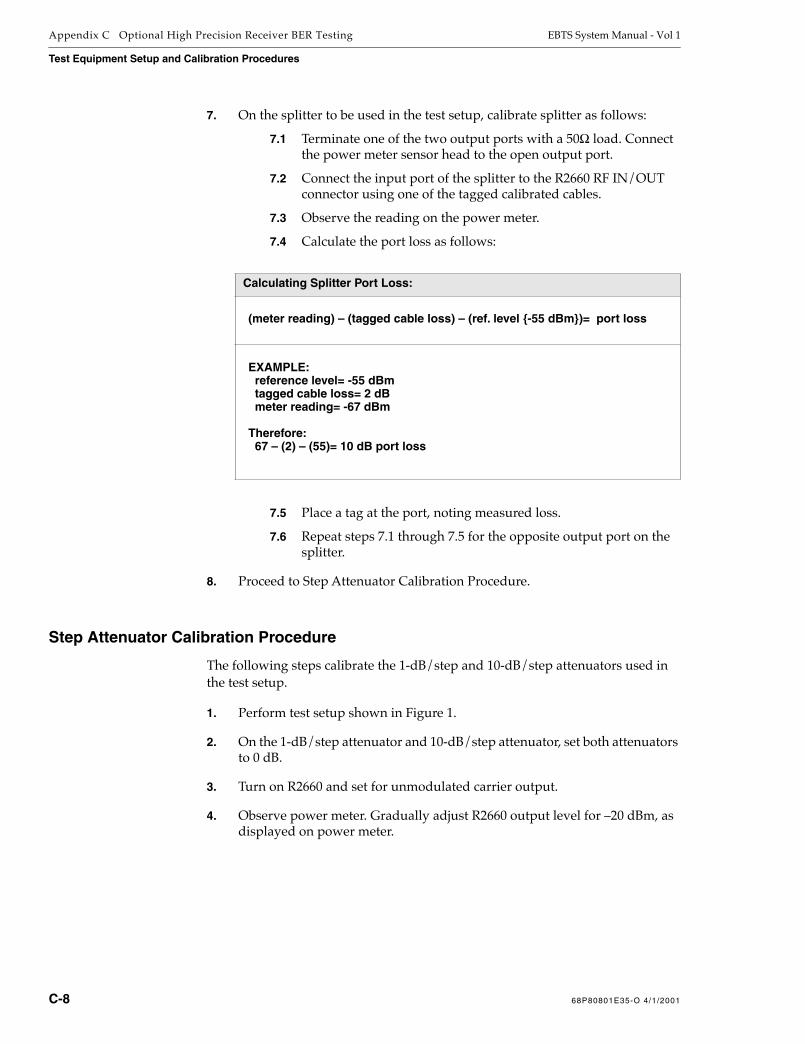
Appendix C Optional High Precision Receiver BER Testing EBTS System Manual - Vol 1
Test Equipment Setup and Calibration Procedures
7. On the splitter to be used in the test setup, calibrate splitter as follows:
7.1 Terminate one of the two output ports with a 50Ω load. Connect the power meter sensor head to the open output port.
7.2 Connect the input port of the splitter to the R2660 RF IN/OUT connector using one of the tagged calibrated cables.
7.3 Observe the reading on the power meter.
7.4 Calculate the port loss as follows:
7.5 Place a tag at the port, noting measured loss.
7.6 Repeat steps 7.1 through 7.5 for the opposite output port on the splitter.
8. Proceed to Step Attenuator Calibration Procedure.
Step Attenuator Calibration Procedure
The following steps calibrate the 1-dB/step and 10-dB/step attenuators used in the test setup.
1. Perform test setup shown in Figure 1.
2. On the 1-dB/step attenuator and 10-dB/step attenuator, set both attenuators to 0 dB.
3. Turn on R2660 and set for unmodulated carrier output.
4. Observe power meter. Gradually adjust R2660 output level for –20 dBm, as displayed on power meter.
Calculating Splitter Port Loss:
(meter reading) – (tagged cable loss) – (ref. level -55 dBm)= port loss
EXAMPLE: reference level= -55 dBm tagged cable loss= 2 dB meter reading= -67 dBm
Therefore: 67 – (2) – (55)= 10 dB port loss
C-8 68P80801E35-O 4/1/2001
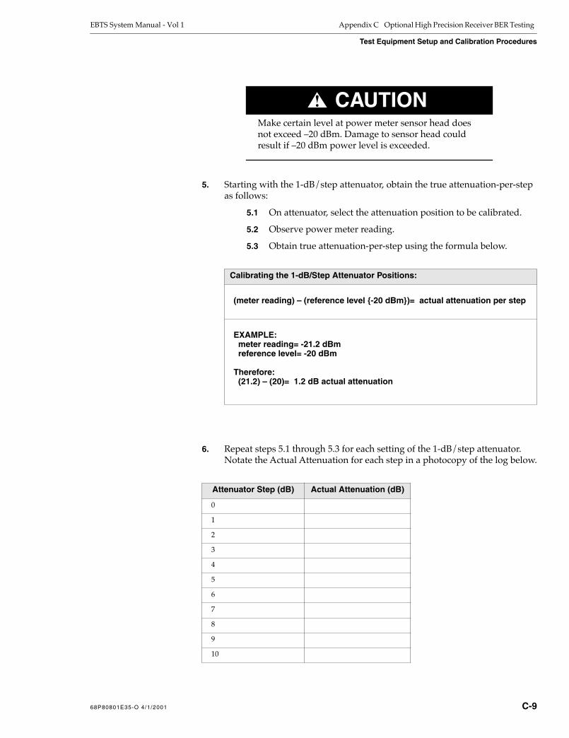
EBTS System Manual - Vol 1 Appendix C Optional High Precision Receiver BER Testing
Test Equipment Setup and Calibration Procedures
CAUTION!Make certain level at power meter sensor head does not exceed –20 dBm. Damage to sensor head could result if –20 dBm power level is exceeded.
5. Starting with the 1-dB/step attenuator, obtain the true attenuation-per-step as follows:
5.1 On attenuator, select the attenuation position to be calibrated.
5.2 Observe power meter reading.
5.3 Obtain true attenuation-per-step using the formula below.
6. Repeat steps 5.1 through 5.3 for each setting of the 1-dB/step attenuator. Notate the Actual Attenuation for each step in a photocopy of the log below.
Calibrating the 1-dB/Step Attenuator Positions:
(meter reading) – (reference level -20 dBm)= actual attenuation per step
EXAMPLE: meter reading= -21.2 dBm reference level= -20 dBm
Therefore: (21.2) – (20)= 1.2 dB actual attenuation
Attenuator Step (dB) Actual Attenuation (dB)
0
1
2
3
4
5
6
7
8
9
10
68P80801E35-O 4/1/2001 C-9

Appendix C Optional High Precision Receiver BER Testing EBTS System Manual - Vol 1
Test Equipment Setup and Calibration Procedures
7. Set the 1-dB/step attenuator to its zero setting.
8. On the 10-dB/step attenuator, repeat the above procedure (steps 5 through 5.3) for the first five settings (0, –10, –20, –30, –40 dB settings) of the attenuator.
Enter the measured values in a photocopy of the log below.
9. Calibrate the 50 and 60 dB attenuation steps of the attenuator as follows:
9.1 Set the 1-dB/step attenuator to 10 dB. Set the 10-dB/step attenuator to 0 dB.
9.2 Gradually adjust the R2660 output level for a reading of –20 dB, as displayed by power meter.
9.3 Set the 10-dB/step attenuator to 50 dB.
9.4 Set the 1-dB/step attenuator to zero.
9.5 Observe power meter reading.
9.6 Calculate and record the actual attenuation value for 50 dB attenuation setting using the formula below.
9.7 Set the 10-dB/step attenuator to 60 dB setting. Repeat steps 9.1 through 9.6 for 60 dB setting. Record value obtained.
Attenuator Step (dB) Actual Attenuation (dB)
0
10
20
30
40
Calibrating 50 dB and 60 dB Attenuator Positions:
(meter reading) + (actual atten. value for “10 dB” – (ref. level -20 dBm) position of 1-dB/step 1-dB/step atten. step 6)
= Actual attenuation per step
EXAMPLE: power meter reading= -59.8 dBm actual atten. value for 10 dB step= 10.4 dB reference level= -20 dBm
Therefore: (59.8) + (10.4) – (20)= 50.2 dB actual attenuation value
C-10 68P80801E35-O 4/1/2001

EBTS System Manual - Vol 1 Appendix C Optional High Precision Receiver BER Testing
Test Equipment Setup and Calibration Procedures
10. Enter the measured values for the 50 and 60 dB steps in a photocopy of the log below.
11. Set R2660 output level control to full counter-clockwise (minimum signal level).
12. On both step attenuators, return settings to zero.
13. Set the R2660 to generate an iDEN BER test signal.
14. Set the power meter averaging function to 9.
15. On R2660, adjust the R2660 output level for a reading of –57.8 dBm on the power meter.
Displayed reading of –57.8 dBm results in actual power level of –50 dBm, thereby compensating for the RF output 1/6 duty cycle.
NOTE
The software version has an effect on the correction factor needed for average power measurements. Older units may require up to 5 db of level offset to compensate for the effects of the training pulse at the beginning of each time slot being larger than published specifications.
16. (See Figure 2.) Without changing any equipment settings, reconfigure the setup as shown by the bold lines in Figure 2.
17. Proceed to Setting Signal Level At Base Radio procedure.
Attenuator Step (dB) Actual Attenuation (dB)
50
60
68P80801E35-O 4/1/2001 C-11

Appendix C Optional High Precision Receiver BER Testing EBTS System Manual - Vol 1
Test Equipment Setup and Calibration Procedures
Figure 2 Receiver Verification Setup
Setting Signal Level At Base Radio
As discussed earlier, all items in the RF path between the R2660 and the Base Radio RX input are now calibrated and require their respective calibration factors to be considered when setting the R2660 output level (power meter reading) for referenced (dBm) levels at the Base Radio.
SPLITTER
R2660TESTSET
RF IN/OUT
O
OI
LOCALSERVICE
COMPUTER(LAPTOP PC)
10dBSTEP
ATTENUATOR
1dBSTEP
ATTENUATOR
SENSORHEAD
CABLE ‘E’
CABLE ‘D’
CABLE ‘C’
CABLE ‘A’
RS232
EBTS410092997JNM
RF POWERMETER
50ΩTERMINATION
CABLE ‘B’
NOTE: BOLD LINES INDICATE REQUIRED CONNECTIONCHANGES. DO NOT CHANGE OTHER CONNECTIONS.
TEST FIXTUREBASE RADIO
STATUS
RX1
RX3
RX2RCVR(S)UNDERTEST
C-12 68P80801E35-O 4/1/2001

EBTS System Manual - Vol 1 Appendix C Optional High Precision Receiver BER Testing
Test Equipment Setup and Calibration Procedures
1. Make certain all items in the RF signal have been calibrated.A checklist of the items that need to be factored are listed below.
2. Set the R2660 output for a target power meter reading that results in the desired level at the Base Radio using the formula below.
An example is shown below.
NOTE
Whenever a target value is arrived at, it must be monitored and maintained throughout the following procedure. Small level adjustments (using the R2660 output level control) may be required in maintaining power meter Target level throughout the course of the procedure.
3. Proceed to BER Sensitivity Test Procedure.
Factors:
D — Desired level at Base Radio.
∑ — Summation (∑) of cal factors (losses and actual attenuator values), consisting of: • cables • splitter • 1-dB step attenuator actual value • 10-dB step attenuator actual value
Formula:
Target power meter reading (T) that R2660 must be set for to produce desired level at Base Radio equals: Desired level at Base Radio + summation of cal factors
T= D+∑
Example:
A desired level of –108.0 dBm is requiredSummation of cal factors (losses) is 60.6 dB, as follows: • 5 dB (cables) • 2 dB (splitter port) • 4.2 dB (actual attenuation value for “4 dB” position of 1-dB step attenuator) • 49.4 dB (actual attenuation value for “50 dB” position of 10-dB step attenuator)
Therefore: (–108.0) + 60.6 = –47.4 dB
R2660 is adjusted for “hotter” output of –47.4 dBm to compensate for 60.6 dB losses and provide true –108.0 dBm at Base Radio RX input
68P80801E35-O 4/1/2001 C-13

Appendix C Optional High Precision Receiver BER Testing EBTS System Manual - Vol 1
BER Sensitivity Test Procedure
BER Sensitivity Test Procedure
Individual procedures are respectively provided for 800 MHz and 900 MHz receiver modules.
Proceed to 800 MHz Receiver Test Procedure or 900 MHz Receiver Test Procedure, as applicable.
800 MHz Receiver Test Procedure
Perform 800 MHz receiver module sensitivity verification as follows:
NOTE
If 3X Receiver is to be tested, refer to “3X Receiver” subsection of Base Radio section of this manual for special compatibility and installation information regarding 3X Receiver installation into a Base Radio.
1. Make certain test fixture Base Radio POWER SUPPLY switch is set to 0 (off).
2. Connect the service computer to the local service port (STATUS connector) of the test fixture Base Radio.
3. Remove power from the R2660 and connect the Rubidium Frequency Standard 10 MHZ OUTPUT to a 10 dB attenuator.
4. Connect the other end of the 10 dB attenuator to the 10 MHZ REFERENCE OSCILLATOR IN/OUT connector on the R2660.
5. Put the R2660 in EXT REF mode.
6. Apply power to the R2660.
7. Set the R2660 to generate the 6/1 iDEN test signal.
NOTE
Refer to the equipment manual provided with the R2660 for further information regarding mode configuration of the unit (Motorola Part No. 68P80309F16).
8. Install receiver module FRU under test into test fixture Base Radio. (If only one receiver module is to be tested, use the RX1 slot.)
C-14 68P80801E35-O 4/1/2001

EBTS System Manual - Vol 1 Appendix C Optional High Precision Receiver BER Testing
BER Sensitivity Test Procedure
9. Set the test fixture Base Radio POWER SUPPLY switch to 1 (on).
10. Log onto the test fixture Base Radio.
11. When prompted, as shown below, enter the password for the test fixture Base Radio.
The default password is motorola.
After entering password, BRC> prompt shown above appears.
12. At the BRC> prompt, type: dekey
This command stops all RF transmission.
WARNING!BE SURE THE DEKEY COMMAND HAS BEEN ISSUED
TO ALL BASE RADIOS IN THE CABINET TO PREVENT
INJURY OR DAMAGE TO EQUIPMENT WHILE
DISCONNECTING AND CONNECTING ANTENNAS.
13. At the BRC> prompt, type: set sgc off
This command disables the software gain control routine within the test fixture Base Radio.
14. At the BRC> prompt, type: get rx_freq
This command displays the receive frequency for the current Base Radio. The message appears as:
Enter login password:
BRC>
BRC> dekey
XMIT OFF INITIATED
BRC> get rx_freq
RECEIVE FREQUENCY is 806.00000 MHz
68P80801E35-O 4/1/2001 C-15

Appendix C Optional High Precision Receiver BER Testing EBTS System Manual - Vol 1
BER Sensitivity Test Procedure
15. Set the R2660 to the receive frequency determined in the previous step.
All receivers within a Base Radio have the same receive frequency.
16. At the BRC> prompt, type: set rx_mode 1
This command enables only antenna/receiver 1 while disabling the remaining antenna/receivers.
NOTE
For the following tests, make sure the R2660 is set to the same frequency as displayed by the get rx_freq command.
17. As shown in Figure 2, connect test cable ‘E’ between the R2660 RF IN/OUT connector and the RX port of the receiver module under test.
18. Noting the required target power meter level and attenuator settings, set the R2660 and attenuators for a desired power level of -108.0 dBm at the end of the cable feeding the Base Radio as follows:
Setting the Target Power Level:
Target power meter level= Desired level at Base Radio + Summation of cal factors
EXAMPLE:A desired level of –108.0 dBm is requiredSummation of cal factors (losses) is 60.6 dB, as follows: • 5 dB (cables) • 2 dB (splitter port) • 4.2 dB (actual attenuation value for “4 dB” position of 1-dB step attenuator) • 49.4 dB (actual attenuation value for “50 dB” position of 10-dB step attenuator)
Therefore: (–108.0) + 60.6 = –47.4 dB
BRC>set rx_mode 1set RECEIVER 1 to ENABLED in RAMset RECEIVER 2 to DISABLED in RAMset RECEIVER 3 to DISABLED in RAM
C-16 68P80801E35-O 4/1/2001
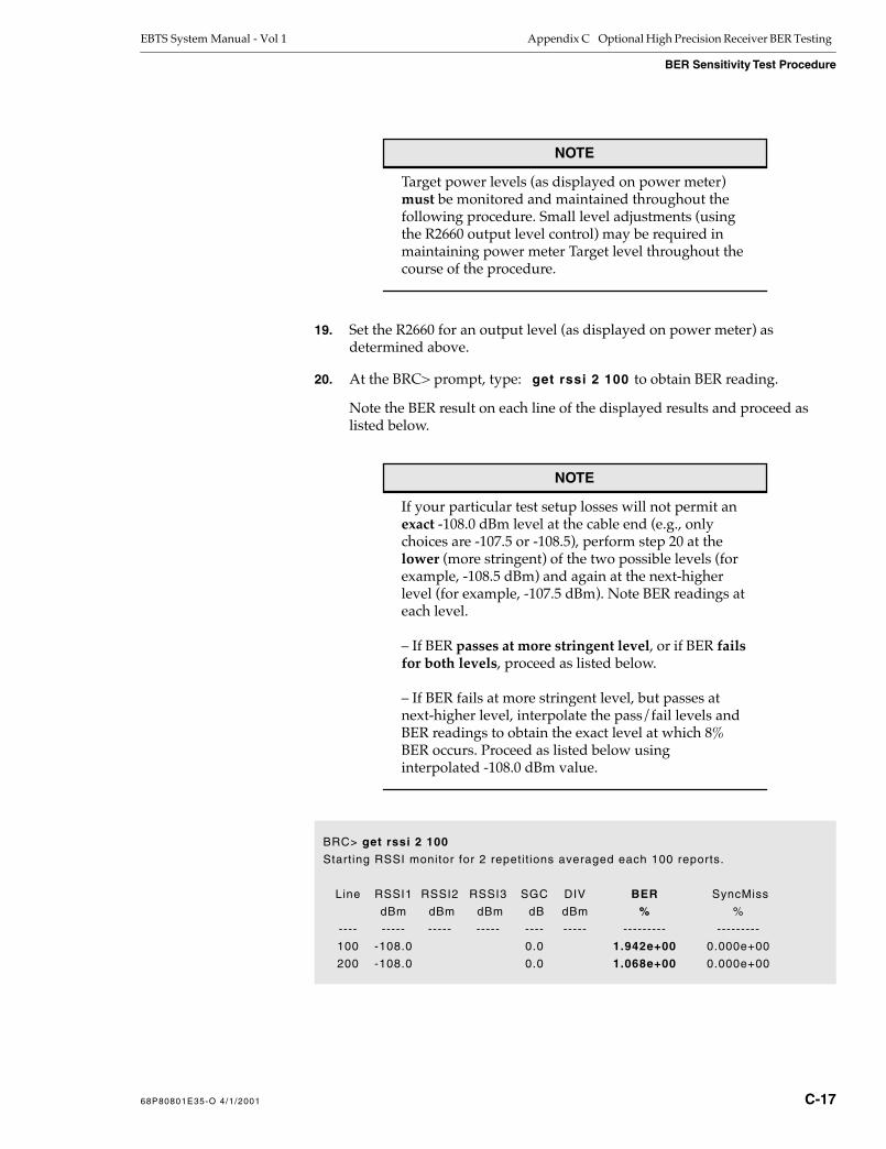
EBTS System Manual - Vol 1 Appendix C Optional High Precision Receiver BER Testing
BER Sensitivity Test Procedure
NOTE
Target power levels (as displayed on power meter) must be monitored and maintained throughout the following procedure. Small level adjustments (using the R2660 output level control) may be required in maintaining power meter Target level throughout the course of the procedure.
19. Set the R2660 for an output level (as displayed on power meter) as determined above.
20. At the BRC> prompt, type: get rssi 2 100 to obtain BER reading.
Note the BER result on each line of the displayed results and proceed as listed below.
NOTE
If your particular test setup losses will not permit an exact -108.0 dBm level at the cable end (e.g., only choices are -107.5 or -108.5), perform step 20 at the lower (more stringent) of the two possible levels (for example, -108.5 dBm) and again at the next-higher level (for example, -107.5 dBm). Note BER readings at each level.
– If BER passes at more stringent level, or if BER fails for both levels, proceed as listed below.
– If BER fails at more stringent level, but passes at next-higher level, interpolate the pass/fail levels and BER readings to obtain the exact level at which 8% BER occurs. Proceed as listed below using interpolated -108.0 dBm value.
BRC> get rssi 2 100
Starting RSSI monitor for 2 repetit ions averaged each 100 reports.
Line RSSI1 RSSI2 RSSI3 SGC DIV BER SyncMiss
dBm dBm dBm dB dBm % %
---- ----- ----- ----- ---- ----- --------- ---------
100 -108.0 0.0 1.942e+00 0.000e+00
200 -108.0 0.0 1.068e+00 0.000e+00
68P80801E35-O 4/1/2001 C-17

Appendix C Optional High Precision Receiver BER Testing EBTS System Manual - Vol 1
BER Sensitivity Test Procedure
• If BER at -108.0 dBm is greater than 8% (8.0e - 00%), Base Radio receiver module is defective. Return module to depot for repair.
• If BER at -108.0 dBm (or better) is 8% (8.0e - 00%) or less, Base Radio receiver module is OK. Re-install module in Base Radio where it was removed.
Refer to System Troubleshooting section for fault isolation of items other than the Base Radio.
21. Depending on whether a Single Receiver FRU or 3X Receiver FRU is being tested, proceed as follows:
• For 3X Receiver FRU, proceed to step 22.
• For Single Receiver FRU, proceed to step 23.
22. Noting the procedure differences below for each receiver branch within the 3X receiver module, repeat steps 16 through 20 for the RX2 receiver, and then for the RX3 receiver.
23. If other receiver modules are to be tested, turn off Base Radio and repeat steps 8 through 21 for each receiver module.
24. After all modules are tested, turn off Base Radio and R2660.
25. Disconnect test setup and reconnect any test fixture cabling removed for this test.
900 MHz Receiver Test Procedure
Perform 900 MHz receiver module sensitivity verification as follows:
1. Make certain test fixture Base Radio POWER SUPPLY switch is set to 0 (off).
2. Connect the service computer to the local service port (STATUS connector) of the test fixture Base Radio.
3. Remove power from the R2660 and connect the Rubidium Frequency Standard 10 MHZ OUTPUT to a 10 dB attenuator.
4. Connect the other end of the 10 dB attenuator to the 10 MHZ REFERENCE OSCILLATOR IN/OUT connector on the R2660.
5. Put the R2660 in EXT REF mode.
Receiver Being Tested
Cable ‘E’ Connection Set Rx Mode Command
RX2 Connect Test Cable ‘E’ to receiver RX2 port.
At the BRC> prompt, type: set rx_mode 2
RX3 Connect Test Cable ‘E’ to receiver RX3 port.
At the BRC> prompt, type: set rx_mode 3
C-18 68P80801E35-O 4/1/2001

EBTS System Manual - Vol 1 Appendix C Optional High Precision Receiver BER Testing
BER Sensitivity Test Procedure
6. Apply power to the R2660.
7. Set the R2660 to generate the 6/1 iDEN test signal.
NOTE
Refer to the equipment manual provided with the R2660 for further information regarding mode configuration of the unit (Motorola Part No. 68P80309F16).
8. Install receiver module FRU under test into test fixture Base Radio.
9. Set the test fixture Base Radio POWER SUPPLY switch to 1 (on).
10. Log onto the test fixture Base Radio.
11. When prompted, as shown below, enter the password for the test fixture Base Radio.
The default password is motorola.
After entering password, BRC> prompt shown above appears.
12. At the BRC> prompt, type: dekey
This command stops all RF transmission.
WARNING!BE SURE THE DEKEY COMMAND HAS BEEN ISSUED
TO ALL BASE RADIOS IN THE CABINET TO PREVENT
INJURY OR DAMAGE TO EQUIPMENT WHILE
DISCONNECTING AND CONNECTING ANTENNAS.
Enter login password:
BRC>
BRC> dekey
XMIT OFF INITIATED
68P80801E35-O 4/1/2001 C-19
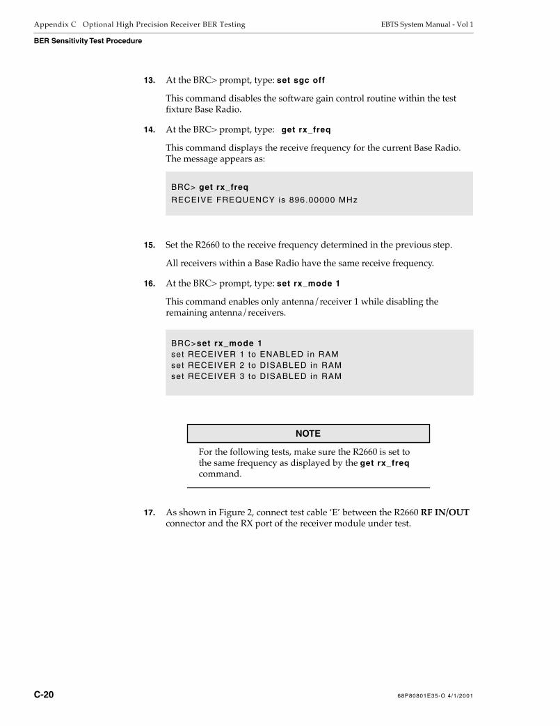
Appendix C Optional High Precision Receiver BER Testing EBTS System Manual - Vol 1
BER Sensitivity Test Procedure
13. At the BRC> prompt, type: set sgc off
This command disables the software gain control routine within the test fixture Base Radio.
14. At the BRC> prompt, type: get rx_freq
This command displays the receive frequency for the current Base Radio. The message appears as:
15. Set the R2660 to the receive frequency determined in the previous step.
All receivers within a Base Radio have the same receive frequency.
16. At the BRC> prompt, type: set rx_mode 1
This command enables only antenna/receiver 1 while disabling the remaining antenna/receivers.
NOTE
For the following tests, make sure the R2660 is set to the same frequency as displayed by the get rx_freq command.
17. As shown in Figure 2, connect test cable ‘E’ between the R2660 RF IN/OUT connector and the RX port of the receiver module under test.
BRC> get rx_freq
RECEIVE FREQUENCY is 896.00000 MHz
BRC>set rx_mode 1set RECEIVER 1 to ENABLED in RAMset RECEIVER 2 to DISABLED in RAMset RECEIVER 3 to DISABLED in RAM
C-20 68P80801E35-O 4/1/2001

EBTS System Manual - Vol 1 Appendix C Optional High Precision Receiver BER Testing
BER Sensitivity Test Procedure
18. Noting the required target power meter level and attenuator settings, set the R2660 and attenuators for a desired power level of -109.0 dBm at the end of the cable feeding the Base Radio as follows:
NOTE
Target power levels (as displayed on power meter) must be monitored and maintained throughout the following procedure. Small level adjustments (using the R2660 output level control) may be required in maintaining power meter Target level throughout the course of the procedure.
19. Set the R2660 for an output level (as displayed on power meter) as determined above.
Setting the Target Power Level:
Target power meter level= Desired level at Base Radio + Summation of cal factors
EXAMPLE:A desired level of –109.0 dBm is requiredSummation of cal factors (losses) is 60.6 dB, as follows: • 5 dB (cables) • 2 dB (splitter port) • 4.2 dB (actual attenuation value for “4 dB” position of 1-dB step attenuator) • 49.4 dB (actual attenuation value for “50 dB” position of 10-dB step attenuator)
Therefore: (–109.0) + 60.6 = –48.4 dB
68P80801E35-O 4/1/2001 C-21

Appendix C Optional High Precision Receiver BER Testing EBTS System Manual - Vol 1
BER Sensitivity Test Procedure
20. At the BRC> prompt, type: get rssi 2 100 to obtain BER reading.
Note the BER result on each line of the displayed results and proceed as listed below.
NOTE
If your particular test setup losses will not permit an exact -109.0 dBm level at the cable end (e.g., only choices are -108.5 or -109.5), perform step 20 at the lower (more stringent) of the two possible levels (for example, -109.5 dBm) and again at the next-higher level (for example, -108.5 dBm). Note BER readings at each level.
– If BER passes at more stringent level, or if BER fails for both levels, proceed as listed below.
– If BER fails at more stringent level, but passes at next-higher level, interpolate the pass/fail levels and BER readings to obtain the exact level at which 10% BER occurs. Proceed as listed below using interpolated -109.0 dBm value.
• If BER at -109.0 dBm is greater than 10% (10.0e - 00%), Base Radio receiver module is defective. Return module to depot for repair.
• If BER at -109.0 dBm (or better) is 10% (10.0e - 00%) or less, Base Radio receiver module is OK. Re-install module in Base Radio where it was removed.
Refer to System Troubleshooting section for fault isolation of items other than the Base Radio.
BRC> get rssi 2 100
Starting RSSI monitor for 2 repetit ions averaged each 100 reports.
Line RSSI1 RSSI2 RSSI3 SGC DIV BER SyncMiss
dBm dBm dBm dB dBm % %
---- ----- ----- ----- ---- ----- --------- ---------
100 -109.0 0.0 1.942e+00 0.000e+00
200 -109.0 0.0 1.068e+00 0.000e+00
C-22 68P80801E35-O 4/1/2001

EBTS System Manual - Vol 1 Appendix C Optional High Precision Receiver BER Testing
BER Sensitivity Test Procedure
21. Noting the procedure differences below for each receiver branch within the 3X receiver module, repeat steps 16 through 20 for the RX2 receiver, and then for the RX3 receiver.
22. If other receiver modules are to be tested, turn off Base Radio and repeat steps 8 through 21 for each receiver module.
23. After all modules are tested, turn off Base Radio and R2660.
24. Disconnect test setup and reconnect any test fixture cabling removed for this test.
Receiver Being Tested
Cable ‘E’ Connection Set Rx Mode Command
RX2 Connect Test Cable ‘E’ to receiver RX2 port.
At the BRC> prompt, type: set rx_mode 2
RX3 Connect Test Cable ‘E’ to receiver RX3 port.
At the BRC> prompt, type: set rx_mode 3
68P80801E35-O 4/1/2001 C-23

Appendix C Optional High Precision Receiver BER Testing EBTS System Manual - Vol 1
BER Sensitivity Test Procedure
This Page Intentionally
Left Blank
C-24 68P80801E35-O 4/1/2001

Index
Numerics
800 MHz Duplexed RFDSChecking receive operation (System Testing section) .................................................................................... 11
Checking transmit operation (System Testing section)................................................................................... 25
Simplified block diagram theory (System Description section) ................................................................... 22
800 MHz GEN 4 Duplexed RFDSChecking receive operation (System Testing section) .................................................................................... 11
Checking transmit operation (System Testing section)................................................................................... 25
FRU listing (Foreword)....................................................................................................................................... xv
Simplified block diagram theory (System Description section) ................................................................... 29
900 MHz Duplexed RFDSChecking receive operation (System Testing section) .................................................................................... 11
Checking transmit operation (System Testing section)................................................................................... 25
FRU listing (Foreword)...................................................................................................................................... xvi
Simplified block diagram theory (System Description section) ................................................................... 50
A
Alarm wiring general requirements (Pre-Installation section) ................................................................... 30
AntennasBase Radio antenna connections to RFDS (Installation section)................................................................. 50
GPS antenna general requirements (Pre-Installation section)...................................................................... 28
GPS antenna planning (Pre-Installation section)............................................................................................ 27
Installation general requirements (Pre-Installation section)......................................................................... 24
RF antenna planning (Pre-Installation section) .............................................................................................. 26
B
Base RadioDisplaying Alarms (System Testing section)...................................................................................................... 8
Dispositioning of Receiver Modules (System Troubleshooting section) .................................................... 14
Fault indications and isolation (System Troubleshooting section) ................................................................. 3
FRU listing (Foreword)...................................................................................................................................... xiv
General description (System Description section) ............................................................................................ 9
Receiver system troubleshooting (System Troubleshooting section)............................................................. 8
Resolving BER failure between Base Radio and RFDS (System Troubleshooting section) ..................... 8
Setting receiver complement (System Testing section) .................................................................................... 8
Setting Rx and Tx frequencies (System Testing section) ............................................................................... 10
Setting/accessing Base Radio cabinet position (System Testing section) ..................................................... 8
Simplified block diagram theory (System Description section) ..................................................................... 9
Battery Float/Equalization (Final Checkout section) ...................................................................................... 9
Network Solutions Sector68P80801E35-O 4/1/2001 1301 E. Algonquin Road, Schaumburg, IL 60196 Index-1

Index EBTS System Manual - Vol 1
Breaker PanelDescription (System Description section)......................................................................................................... 13
C
CabinetComplements used for various systems (Installation section)........................................................................ 2
Dimensions (Pre-Installation section) ................................................................................................................ 3
Footprint (Pre-Installation section)..................................................................................................................... 4
Ground cabling (Installation section) ............................................................................................................... 44
Installation (Installation section) ......................................................................................................................... 5
Power-Up procedure (Final Checkout section) ............................................................................................... 14
Receive cabling (See appropriate RFDS or EBTS system section)Transmit Cabling (See appropriate RFDS or EBTS system section)
Cabinet Power Distribution and Interconnect Hardware (General description, types of) (System Description section) ....................................................................................................................................................... 13
Cabinet-to-Site CablingAC mains connection (SRSC system) (Installation section) ........................................................................ 38
Base Radio antenna connections (Installation section).................................................................................. 50
Battery backup connection (SRSC system) (Installation section) ............................................................... 41
Equipment cabinet ground connections (Installation section)...................................................................... 44
Cavity Combining RFDSFRU listing (Foreword)....................................................................................................................................... xv
Simplified block diagram theory (System Description section) ................................................................... 46
E
EBTSCabinet configurations (terminology and definitions) (System Description section) ................................. 6
Component descriptions (System Description section) .................................................................................... 9
Configuration descriptions (System Description section).............................................................................. 20
Overall functional description (System Description section) .......................................................................... 3
Site description (System Description section).................................................................................................... 2
Equipment inspection (Pre-Installation section)............................................................................................. 11
Equipment inventory (Pre-Installation section) .............................................................................................. 12
Equipment unpacking (Pre-Installation section) ............................................................................................ 11
F
Fault IsolationBase Radio (System Troubleshooting section)................................................................................................... 3
General information (System Troubleshooting section)................................................................................... 2
Miscellaneous troubleshooting (System Troubleshooting section) .............................................................. 18
RFDS (System Troubleshooting section).......................................................................................................... 15
Field Replaceable Units
Index-2 68P80801E35-O 4/1/2001
EBTS System Manual - Vol 1 Index
Available FRUs (Foreword) ..............................................................................................................................xiii
Final Checkout Setup (Final Checkout section) ................................................................................................ 3
G
Grounding Requirements (Pre-Installation section)...................................................................................... 18
I
InstallationCabinet (Installation section) ............................................................................................................................... 5
Power Supply Rack (Installation section) .......................................................................................................... 8
Recommended Tools, Equipment, and Parts (Pre-Installation section) ..................................................... 31
integrated Dispatch Enhanced NetworkBlock diagram (System Description section) ..................................................................................................... 2
integrated Site ControllerGeneral description (System Description section) .......................................................................................... 11
Intercabinet Cabling5 MHz/1 PPS (Installation section)................................................................................................................... 13
Alarm-to-iMU (Installation section) ................................................................................................................. 26
Ethernet (Installation section) ............................................................................................................................ 21
PCCH (Installation section)................................................................................................................................ 33
Power Supply rack-to-EBTS (Installation section) ........................................................................................ 34
Receive cabling (See appropriate RFDS or EBTS system section)Transmit cabling (See appropriate RFDS or EBTS system section)
J
Junction Panels (general description) (System Description section) .......................................................... 18
M
Maintenance Philosophy (Foreword) .................................................................................................................xii
MMI CommandsAccess level (Software Commands section) ...................................................................................................... 2
Base Radio (Software Commands section) ........................................................................................................ 4
Conventions (Software Commands section) ...................................................................................................... 3
General information (Software Commands section)......................................................................................... 2
Motorola Customer Support CenterSupport Center address and phone number (Foreword) ................................................................................xii
O
Omni/Sectored Site (defined) (Installation section).......................................................................................... 2
Optional High Precision BER Testing
68P80801E35-O 4/1/2001 Index-3
Index EBTS System Manual - Vol 1
BER sensitivity test procedure (Appendix C) ............................................................................................ C - 14
Test equipment and shop fixture setup (Appendix C)................................................................................. C - 2
Test equipment setup and calibration procedures (Appendix C) .............................................................. C - 4
P
Parts and Suppliers (Appendix B)
Power Supply RackGeneral information (Pre-Installation section) ............................................................................................... 16
Powering the Power Supply System (Final Checkout section) ...................................................................... 6
Power-upComponents within equipment cabinets (Final Checkout section).............................................................. 16
Equipment cabinets (Final Checkout section) ................................................................................................. 14
Purpose of Manual (Foreword).............................................................................................................................. x
R
Receiver SystemExcessive BER fault isolation (System Troubleshooting section).................................................................. 8
Recommended Test Equipment (general requirements) (Pre-Installation section)............................... 34
RF Cabinet-48 VDC power connections (Installation section) ........................................................................................ 36
Base Radio antenna connections (Installation section).................................................................................. 50
Dimensions (Pre-Installation section) ................................................................................................................ 3
Footprint (Pre-Installation section)..................................................................................................................... 4
Power requirements (Pre-Installation section)................................................................................................ 17
Test Equipment (System Testing section) ........................................................................................................... 4
Verification (System Testing section).................................................................................................................. 4
Weight and floor loading data (Pre-Installation section) ................................................................................ 5
RF Distribution System (see RFDS)
RFDSFault isolation (System Troubleshooting section) ........................................................................................... 15
General description, types of (System Description section) .......................................................................... 11
Resolving BER failure between Base Radio and RFDS (System Troubleshooting section) ..................... 8
S
Single Rack, Redundant Controller GEN 4 EBTSChecking receive operation (System Testing section) .................................................................................... 11
Checking transmit operation (System Testing section)................................................................................... 25
FRU listing (Foreword)....................................................................................................................................... xv
Simplified block diagram theory (System Description section) ................................................................... 37
Single Rack, Single Controller GEN 4 EBTS
Index-4 68P80801E35-O 4/1/2001

EBTS System Manual - Vol 1 Index
Checking receive operation (System Testing section) .................................................................................... 11
Checking transmit operation (System Testing section)................................................................................... 25
FRU listing (Foreword)....................................................................................................................................... xv
Simplified block diagram theory (System Description section) ................................................................... 43
T
Transmit Spectrum (viewing) (System Testing section)................................................................................. 30
Troubleshooting (see Fault Isolation)
V
VerificationiSC (System Testing section)................................................................................................................................. 3
RF Cabinet (System Testing section)................................................................................................................... 4
68P80801E35-O 4/1/2001 Index-5

Index EBTS System Manual - Vol 1
This Page Intentionally
Left Blank
Index-6 68P80801E35-O 4/1/2001