02 up8086 internal arch
DESCRIPTION
asdTRANSCRIPT

(C2)
80x86 Internal Architecture

Computer Operation Model FETCH Instruction - EXECUTE Instruction
FETCH EXECUTE FETCH EXECUTE FETCH EXECUTE
time
FETCH 1) Read Instruction from Memory
2) Decode/Interpret Instruction
3) Increment Instruction Address Register
EXECUTE 1) Control Unit - Input is Decoded Instruction
2) Control Signals Set
3) Data is Processed

8086 Architecture Specifics BIU and EU - Pipelined Arrangement
• BIU - Bus Interface Unit
• Instruction Pipeline
• EU - Execution Unit • Pipeline - Hardware Designed for Parallel Operation
FETCH
EXECUTE
FETCH
EXECUTE
FETCH
EXECUTE WAIT
FETCH FETCH GET DATA
EU
BIU
time

8086 Internal Architecture Execution Model

8086 Overall Architecture BIU and EU - Pipelined Arrangement
EXECUTION
UNIT EU
BUS
INTERFACE
UNIT BIU
System Bus (PC Bus)
Instruction
Pipeline


ALU/EXECUT
ADD AH
BH
CH
AL
BL
CL
DL
BP
DI
SI
SP
DH
CS
ES
SS
DS
IP
Instr. Decode;
Bus Controller
1
2
3
4
5
6
SYSTEM BUS (Internal)
FLAGS
EU Instruction
Queue
BIU
Data Bus Address Bus

Content of the EU:…… Content of the BIU: ….
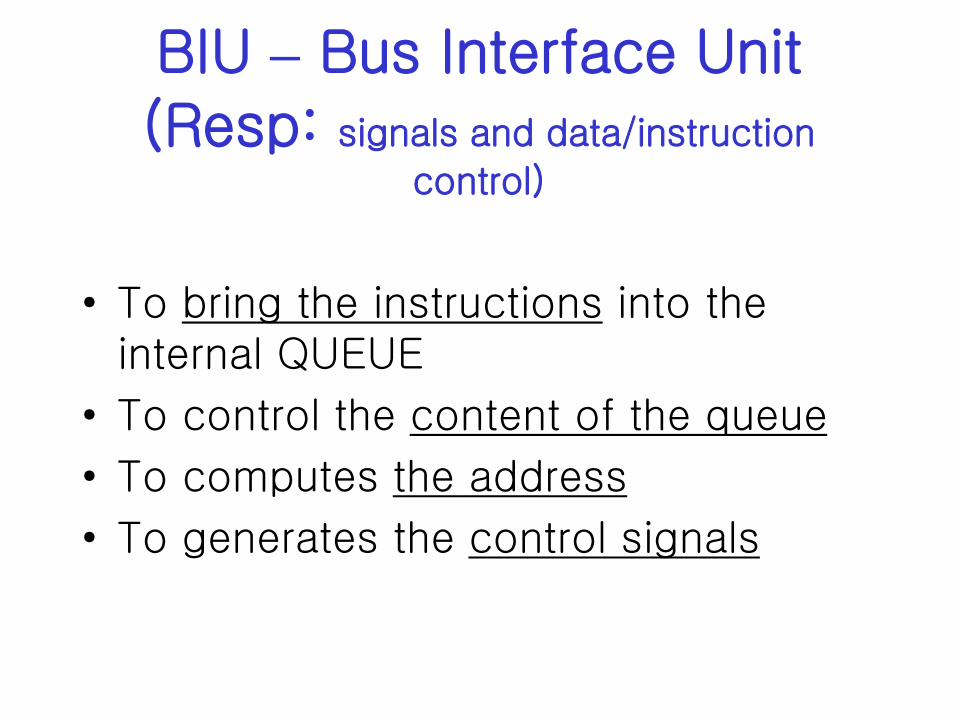
BIU – Bus Interface Unit
(Resp: signals and data/instruction
control)
• To bring the instructions into the internal QUEUE
• To control the content of the queue
• To computes the address
• To generates the control signals

BIU - contents
• Bloc for controlling the signals
• FIFO memory to implement the 6 bytes queue
• Instruction pointer (next instruction to be executed)
• ALU to calculate the address
• Internal communication registers
• Registers for memory segmentation

EU – Execution Unit
• Decoding of instructions
• ALU
• General registers (accessible by user)
• Internal registers (internal operations)
• Register to store the status and control of the program

CS
DS
SS
ES
AH
BH
CH
DH
AL
BL
CL
DL
IP
SP
BP
SI
DI
0 7
0 15
0 7
0 15
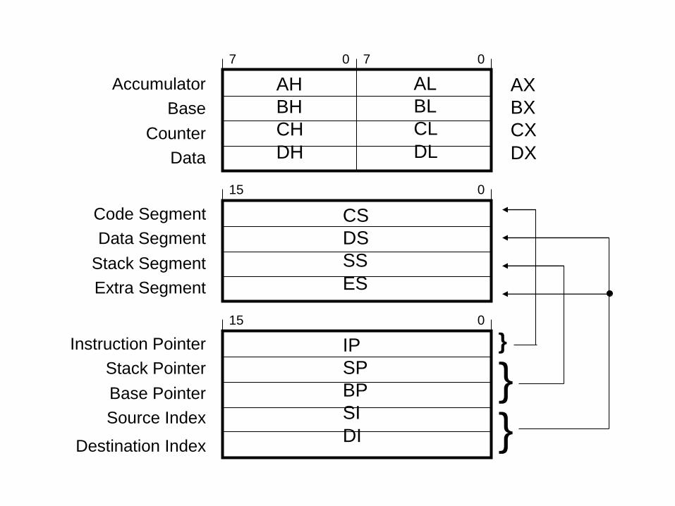
Accumulator
Base
Counter
Data
Code Segment
Data Segment
Stack Segment
Extra Segment
Instruction Pointer
Stack Pointer
Base Pointer
Source Index
Destination Index
}
} }
AX
BX
CX
DX

For 32 bit processors: AX register (16b) EAX (32b)

8086/8088 Register File (cont) Instruction Pointer Register
0 15
IP Contains Address of NEXT Instruction to be Fetched
– Automatically Incremented
– Programmer can Control with jump and branch
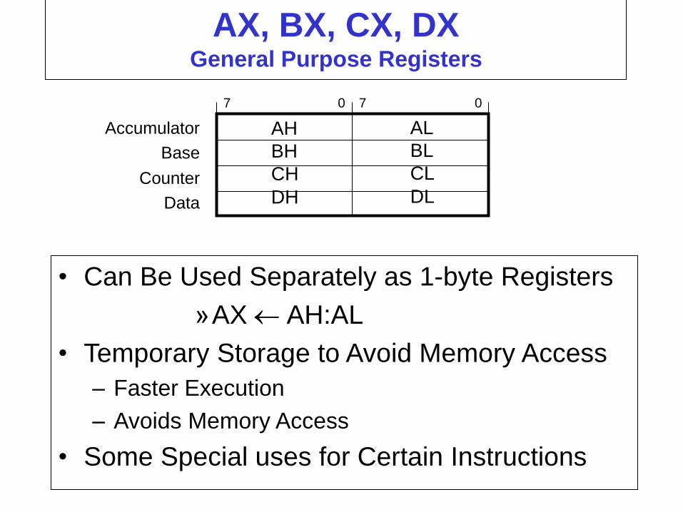
AX, BX, CX, DX General Purpose Registers
• Can Be Used Separately as 1-byte Registers
»AX AH:AL
• Temporary Storage to Avoid Memory Access
– Faster Execution
– Avoids Memory Access
• Some Special uses for Certain Instructions
AH
BH
CH
DH
AL
BL
CL
DL
0 7 0 7
Accumulator
Base
Counter
Data

AX, BX, CX, DX General Purpose Registers - Some Specialized Uses
• AX, Accumulator
– Main Register for Performing Arithmetic
– mult/div must use AH, AL
– “accumulator” Means Register with Simple ALU
• BX, Base
– Point to Translation Table in Memory
– Holds Memory Offsets; Function Calls
• CX, Counter
– Index Counter for Loop Control
• DX, Data
– After Integer Division Execution - Holds Remainder
AH
BH
CH
DH
AL
BL
CL
DL
0 7 0 7
Accumulator
Base
Counter
Data

CS, DS, ES, SS - Segment
Registers Contains “Base Value” for Memory Address
• CS, Code Segment
– Used to “point” to Instructions
– Determines a Memory Address (along with IP)
– Segmented Address written as CS:IP
• DS, Data Segment
– Used to “point” to Data
– Determines Memory Address (along with other registers)
– ES, Extra Segment allows 2 Data Address Registers
• SS, Stack Segment
– Used to “point” to Data in Stack Structure (LIFO)
– Used with SP or BP
– SS:SP or SP:BP are valid Segment Addresses


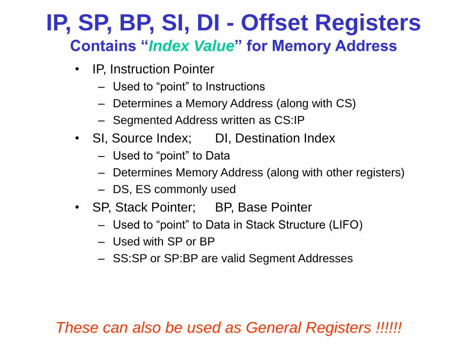
IP, SP, BP, SI, DI - Offset Registers Contains “Index Value” for Memory Address
• IP, Instruction Pointer
– Used to “point” to Instructions
– Determines a Memory Address (along with CS)
– Segmented Address written as CS:IP
• SI, Source Index; DI, Destination Index
– Used to “point” to Data
– Determines Memory Address (along with other registers)
– DS, ES commonly used
• SP, Stack Pointer; BP, Base Pointer
– Used to “point” to Data in Stack Structure (LIFO)
– Used with SP or BP
– SS:SP or SP:BP are valid Segment Addresses
These can also be used as General Registers !!!!!!

8086/8088 Register File (cont) Flags Register
x x x x OF DF IF TF SF ZF x AF x PF x CF
0 15
Status and Control Bits Maintained in Flags Register
– Generally Set and Tested Individually
– 9 1-bit flags in 8086; 7 are unused
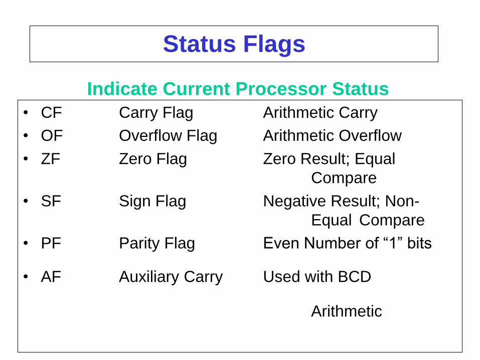
Status Flags
• CF Carry Flag Arithmetic Carry
• OF Overflow Flag Arithmetic Overflow
• ZF Zero Flag Zero Result; Equal
Compare
• SF Sign Flag Negative Result; Non-
Equal Compare
• PF Parity Flag Even Number of “1” bits
• AF Auxiliary Carry Used with BCD
Arithmetic
Indicate Current Processor Status

Control Flags Influence the 8086 During Execution Phase
• DF: Direction Flag Increment/Decrement
– used for “string operations”
• IF: Interrupt Flag Enables Interrupts
– allows “fetch-execute” to be interrupted
• TF Trap Flag Allows Single-Step
– for debugging; causes interrupt after each op
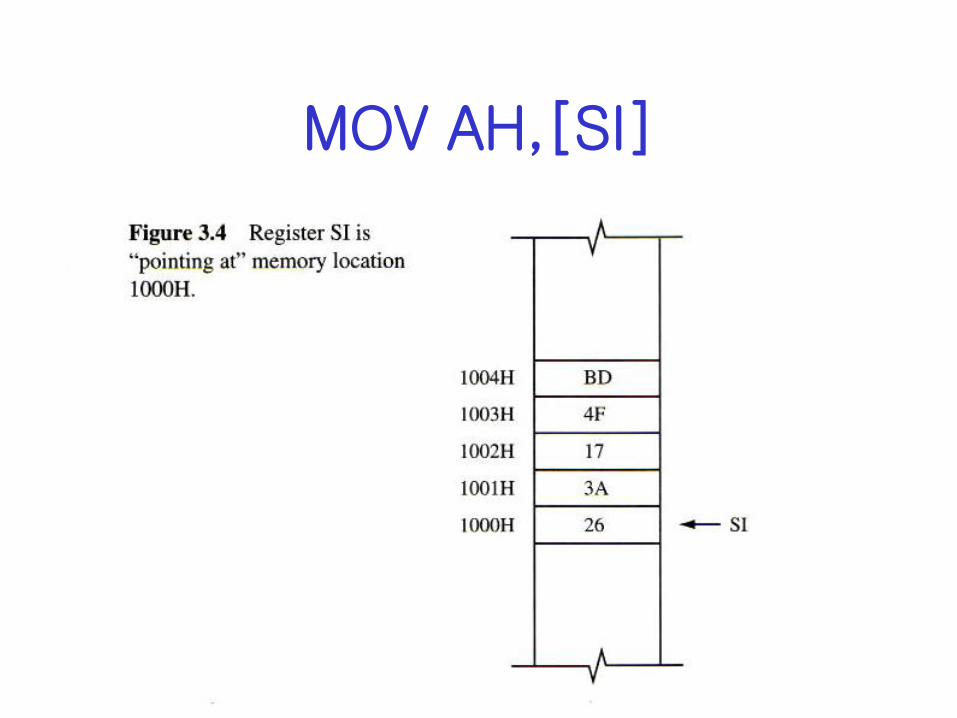
MOV AH,[SI]
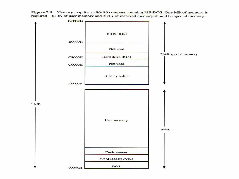

8086 Segmented Memory
• x86 Memory Partitioned into Segments – 8086: maximum size is 64K (16-bit index reg.) – 8086: can have 4 active segments (CS, SS, DS, ES)
– 8086: 2-data; 1-code; 1-stack – x386: maximum size is 4GB (32-bit index reg.) – x386: can have 6 active segments (4-data; FS, GS)
• Why have segmented memory ???????? •Other microprocessors could only address 64K since they
only had a single 16-bit MemAddrReg (or smaller).
Segments allowed computers to be built that could use more
than 64K memory (but not all at the same time).


8086/8088 Memory Access Registers
CS
DS
SS
ES
IP
SP
BP
SI
DI
0 15
0 15
Code Segment
Data Segment
Stack Segment
Extra Segment
Instruction Pointer
Stack Pointer
Base Pointer
Source Index
Destination Index
}
} }
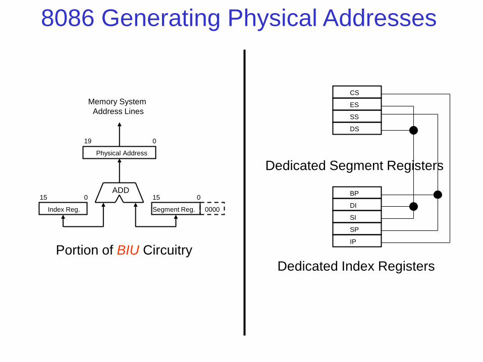
ADD
CS
ES
SS
DS
IP
Memory System
Address Lines
0000 Index Reg. Segment Reg.
Physical Address
0 0
0
15 15
19
Portion of BIU Circuitry
Dedicated Segment Registers
Dedicated Index Registers
BP
DI
SI
SP
8086 Generating Physical Addresses

Segmented Addressing
CS
ES
SS
DS
IP
BP
DI
SI
SP
• Each Segment must begin at Paragraph Boundary
00000h
00010h
00020h
physical address memory
paragraph 1
paragraph 2
paragraph 3
• Each paragraph has phys. address that is multiple of 10h
• BIU is responsible for appending 0000 to Segment
– only need 16-bit segment registers


Segmented Memory (x86 Style)
CS
ES
SS
DS
Data
Segment
Stack
Segment
Extra
Segment
Code
Segment
Segment
Registers
System
Memory
• Segment Registers: – Point to Base Address
• Index Registers: – Contain Offset Value
– • Notation (Segmented Address):
– CS:IP – DS:SI – ES:DI – SS:BP – SS:SP
00000h
FFFFFh
fragmentation

Memory Storage Organization
• Organized as SEGMENTS – Maximum segment size = 64KB
– (Since 16 bit offsets: 216 = 65,535 = 64KB)
• Maximum Memory Size: – 220 = 1,048,576 = 1MB
• Newer Processors (Pentium) Can Utilize More Memory – Wider Address Registers 32 bits
– 232 = 4,294,967,296 = 4GB
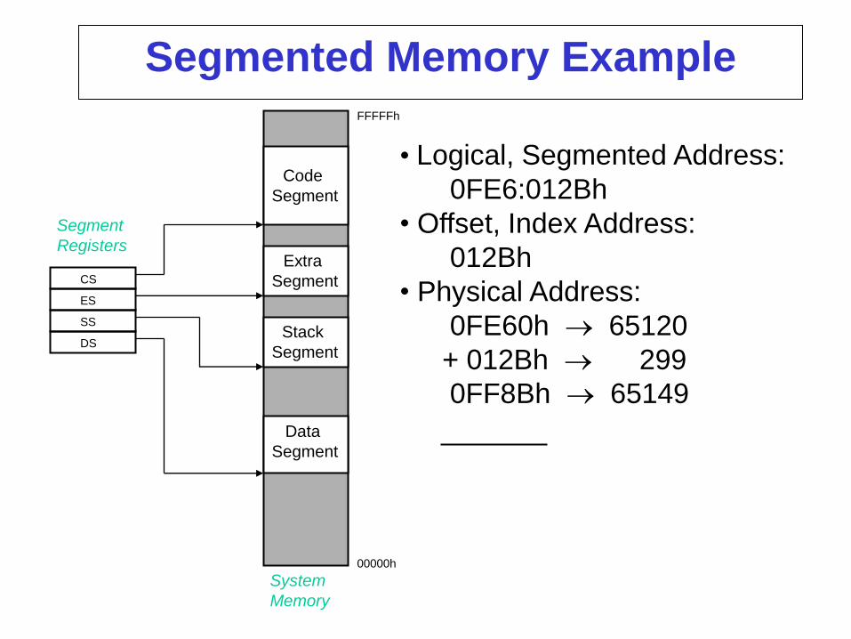
Segmented Memory Example
CS
ES
SS
DS
Data
Segment
Stack
Segment
Extra
Segment
Code
Segment
Segment
Registers
System
Memory
• Logical, Segmented Address: 0FE6:012Bh
• Offset, Index Address: 012Bh
• Physical Address: 0FE60h 65120 + 012Bh 299 0FF8Bh 65149
00000h
FFFFFh

Segmented Memory Aliasing
• Logical, Segmented Address 1: DS:SI = 1234:4321
• Physical Address: 12340h 74560 + 4321h 17185 16661h 91745
• Logical, Segmented Address 2: ES:DI = 1665:0011
• Physical Address: 16650h 91728 + 0011h 00017 16661h 91745

Segment Locations in Physical Memory

• 1 Word = 16 bits • Byte Addressable • Little Endian Arrangement
– MSB (Most Significant Byte) at Higher Address
0727H
0726H
0725H
0724H
0723H
0722H
072CH
072BH
072AH
0729H
0728H
• Base Address = ACEDH
AD5F4H
AD5F3H
AD5F2H
AD5FCH
AD5FBH
AD5FAH
AD5F9H
AD5F8H
AD5F7H
AD5F6H
AD5F5H
• Logical Address = 0724H
• Physical Address
= ACED0H + 0724H
= AD5F4H
• M[ACED:0724]
= M[AD5F4]
= 5502H 02H
18H
A3H
7EH
69H
AAH
2EH
00H
55H
11H
72H
0H 2H 5H 5H
0101 0101 0010 0000
0724H 0725H
hex
binary

0727H
0726H
0725H
0724H
0723H
0722H
072CH
072BH
072AH
0729H
0728H
AD5F4H
AD5F3H
AD5F2H
AD5FCH
AD5FBH
AD5FAH
AD5F9H
AD5F8H
AD5F7H
AD5F6H
AD5F5H
55H
18H
A3H
7EH
69H
AAH
2EH
00H
02H
20H
11H
AD5F1H
AD5F0H
AD5EFH
AD5EEH
AD5EDH
AD5ECH
0721H
0720H
071FH
071EH
071DH
071CH
72H
DEH
ADH
FAH
CEH
CAH
FEH
Assume:
M[DS:DI] Contains a Pointer Value
DS = AD5Fh; DI = 0005h
(All Segments Start on Paragraph Boundary)
SI M[DS:DI]
Then:
Pointer is M[DS:DI] = M[AD5F:0005]
= M[AD5F5] = 0002h
M[DS:SI] = M[DS:(DS:DI)] = M[DS:0002h]
= M[AD5F:0002] = M[AD5F2] = 1120h
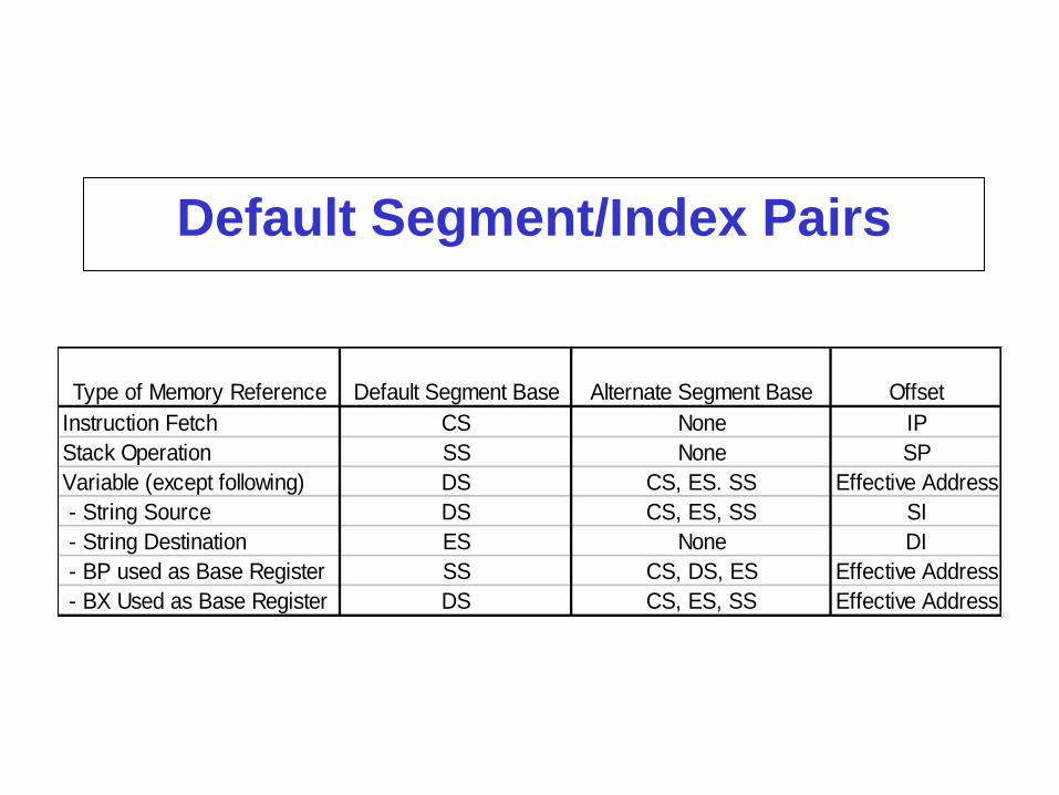
Default Segment/Index Pairs
Type of Memory Reference Default Segment Base Alternate Segment Base Offset
Instruction Fetch CS None IP
Stack Operation SS None SP
Variable (except following) DS CS, ES. SS Effective Address
- String Source DS CS, ES, SS SI
- String Destination ES None DI
- BP used as Base Register SS CS, DS, ES Effective Address
- BX Used as Base Register DS CS, ES, SS Effective Address


Homework:
Give several exercises
Keypoints